EP4324724A1 - Motor driven power steering system of redundancy structure - Google Patents
Motor driven power steering system of redundancy structure Download PDFInfo
- Publication number
- EP4324724A1 EP4324724A1 EP22211406.8A EP22211406A EP4324724A1 EP 4324724 A1 EP4324724 A1 EP 4324724A1 EP 22211406 A EP22211406 A EP 22211406A EP 4324724 A1 EP4324724 A1 EP 4324724A1
- Authority
- EP
- European Patent Office
- Prior art keywords
- processor
- driving
- position sensor
- motor
- driving motor
- Prior art date
- Legal status (The legal status is an assumption and is not a legal conclusion. Google has not performed a legal analysis and makes no representation as to the accuracy of the status listed.)
- Granted
Links
Images

Classifications
-
- B—PERFORMING OPERATIONS; TRANSPORTING
- B62—LAND VEHICLES FOR TRAVELLING OTHERWISE THAN ON RAILS
- B62D—MOTOR VEHICLES; TRAILERS
- B62D5/00—Power-assisted or power-driven steering
- B62D5/04—Power-assisted or power-driven steering electrical, e.g. using an electric servo-motor connected to, or forming part of, the steering gear
- B62D5/0457—Power-assisted or power-driven steering electrical, e.g. using an electric servo-motor connected to, or forming part of, the steering gear characterised by control features of the drive means as such
- B62D5/046—Controlling the motor
- B62D5/0463—Controlling the motor calculating assisting torque from the motor based on driver input
-
- B—PERFORMING OPERATIONS; TRANSPORTING
- B62—LAND VEHICLES FOR TRAVELLING OTHERWISE THAN ON RAILS
- B62D—MOTOR VEHICLES; TRAILERS
- B62D5/00—Power-assisted or power-driven steering
- B62D5/04—Power-assisted or power-driven steering electrical, e.g. using an electric servo-motor connected to, or forming part of, the steering gear
- B62D5/0457—Power-assisted or power-driven steering electrical, e.g. using an electric servo-motor connected to, or forming part of, the steering gear characterised by control features of the drive means as such
- B62D5/0481—Power-assisted or power-driven steering electrical, e.g. using an electric servo-motor connected to, or forming part of, the steering gear characterised by control features of the drive means as such monitoring the steering system, e.g. failures
- B62D5/0484—Power-assisted or power-driven steering electrical, e.g. using an electric servo-motor connected to, or forming part of, the steering gear characterised by control features of the drive means as such monitoring the steering system, e.g. failures for reaction to failures, e.g. limp home
-
- B—PERFORMING OPERATIONS; TRANSPORTING
- B62—LAND VEHICLES FOR TRAVELLING OTHERWISE THAN ON RAILS
- B62D—MOTOR VEHICLES; TRAILERS
- B62D5/00—Power-assisted or power-driven steering
- B62D5/04—Power-assisted or power-driven steering electrical, e.g. using an electric servo-motor connected to, or forming part of, the steering gear
- B62D5/0409—Electric motor acting on the steering column
-
- B—PERFORMING OPERATIONS; TRANSPORTING
- B62—LAND VEHICLES FOR TRAVELLING OTHERWISE THAN ON RAILS
- B62D—MOTOR VEHICLES; TRAILERS
- B62D5/00—Power-assisted or power-driven steering
- B62D5/04—Power-assisted or power-driven steering electrical, e.g. using an electric servo-motor connected to, or forming part of, the steering gear
- B62D5/0457—Power-assisted or power-driven steering electrical, e.g. using an electric servo-motor connected to, or forming part of, the steering gear characterised by control features of the drive means as such
- B62D5/046—Controlling the motor
-
- B—PERFORMING OPERATIONS; TRANSPORTING
- B62—LAND VEHICLES FOR TRAVELLING OTHERWISE THAN ON RAILS
- B62D—MOTOR VEHICLES; TRAILERS
- B62D5/00—Power-assisted or power-driven steering
- B62D5/04—Power-assisted or power-driven steering electrical, e.g. using an electric servo-motor connected to, or forming part of, the steering gear
- B62D5/0457—Power-assisted or power-driven steering electrical, e.g. using an electric servo-motor connected to, or forming part of, the steering gear characterised by control features of the drive means as such
- B62D5/0481—Power-assisted or power-driven steering electrical, e.g. using an electric servo-motor connected to, or forming part of, the steering gear characterised by control features of the drive means as such monitoring the steering system, e.g. failures
-
- B—PERFORMING OPERATIONS; TRANSPORTING
- B62—LAND VEHICLES FOR TRAVELLING OTHERWISE THAN ON RAILS
- B62D—MOTOR VEHICLES; TRAILERS
- B62D5/00—Power-assisted or power-driven steering
- B62D5/04—Power-assisted or power-driven steering electrical, e.g. using an electric servo-motor connected to, or forming part of, the steering gear
- B62D5/0457—Power-assisted or power-driven steering electrical, e.g. using an electric servo-motor connected to, or forming part of, the steering gear characterised by control features of the drive means as such
- B62D5/0481—Power-assisted or power-driven steering electrical, e.g. using an electric servo-motor connected to, or forming part of, the steering gear characterised by control features of the drive means as such monitoring the steering system, e.g. failures
- B62D5/0487—Power-assisted or power-driven steering electrical, e.g. using an electric servo-motor connected to, or forming part of, the steering gear characterised by control features of the drive means as such monitoring the steering system, e.g. failures detecting motor faults
-
- B—PERFORMING OPERATIONS; TRANSPORTING
- B62—LAND VEHICLES FOR TRAVELLING OTHERWISE THAN ON RAILS
- B62D—MOTOR VEHICLES; TRAILERS
- B62D5/00—Power-assisted or power-driven steering
- B62D5/04—Power-assisted or power-driven steering electrical, e.g. using an electric servo-motor connected to, or forming part of, the steering gear
- B62D5/0457—Power-assisted or power-driven steering electrical, e.g. using an electric servo-motor connected to, or forming part of, the steering gear characterised by control features of the drive means as such
- B62D5/0481—Power-assisted or power-driven steering electrical, e.g. using an electric servo-motor connected to, or forming part of, the steering gear characterised by control features of the drive means as such monitoring the steering system, e.g. failures
- B62D5/049—Power-assisted or power-driven steering electrical, e.g. using an electric servo-motor connected to, or forming part of, the steering gear characterised by control features of the drive means as such monitoring the steering system, e.g. failures detecting sensor failures
-
- H—ELECTRICITY
- H02—GENERATION; CONVERSION OR DISTRIBUTION OF ELECTRIC POWER
- H02P—CONTROL OR REGULATION OF ELECTRIC MOTORS, ELECTRIC GENERATORS OR DYNAMO-ELECTRIC CONVERTERS; CONTROLLING TRANSFORMERS, REACTORS OR CHOKE COILS
- H02P6/00—Arrangements for controlling synchronous motors or other dynamo-electric motors using electronic commutation dependent on the rotor position; Electronic commutators therefor
- H02P6/14—Electronic commutators
- H02P6/16—Circuit arrangements for detecting position
-
- B—PERFORMING OPERATIONS; TRANSPORTING
- B60—VEHICLES IN GENERAL
- B60Y—INDEXING SCHEME RELATING TO ASPECTS CROSS-CUTTING VEHICLE TECHNOLOGY
- B60Y2306/00—Other features of vehicle sub-units
- B60Y2306/13—Failsafe arrangements
-
- B—PERFORMING OPERATIONS; TRANSPORTING
- B60—VEHICLES IN GENERAL
- B60Y—INDEXING SCHEME RELATING TO ASPECTS CROSS-CUTTING VEHICLE TECHNOLOGY
- B60Y2306/00—Other features of vehicle sub-units
- B60Y2306/15—Failure diagnostics
-
- B—PERFORMING OPERATIONS; TRANSPORTING
- B62—LAND VEHICLES FOR TRAVELLING OTHERWISE THAN ON RAILS
- B62D—MOTOR VEHICLES; TRAILERS
- B62D15/00—Steering not otherwise provided for
- B62D15/02—Steering position indicators ; Steering position determination; Steering aids
- B62D15/021—Determination of steering angle
- B62D15/0235—Determination of steering angle by measuring or deriving directly at the electric power steering motor
-
- B—PERFORMING OPERATIONS; TRANSPORTING
- B62—LAND VEHICLES FOR TRAVELLING OTHERWISE THAN ON RAILS
- B62D—MOTOR VEHICLES; TRAILERS
- B62D5/00—Power-assisted or power-driven steering
- B62D5/001—Mechanical components or aspects of steer-by-wire systems, not otherwise provided for in this maingroup
- B62D5/005—Mechanical components or aspects of steer-by-wire systems, not otherwise provided for in this maingroup means for generating torque on steering wheel or input member, e.g. feedback
- B62D5/006—Mechanical components or aspects of steer-by-wire systems, not otherwise provided for in this maingroup means for generating torque on steering wheel or input member, e.g. feedback power actuated
-
- B—PERFORMING OPERATIONS; TRANSPORTING
- B62—LAND VEHICLES FOR TRAVELLING OTHERWISE THAN ON RAILS
- B62D—MOTOR VEHICLES; TRAILERS
- B62D5/00—Power-assisted or power-driven steering
- B62D5/04—Power-assisted or power-driven steering electrical, e.g. using an electric servo-motor connected to, or forming part of, the steering gear
- B62D5/0403—Power-assisted or power-driven steering electrical, e.g. using an electric servo-motor connected to, or forming part of, the steering gear characterised by constructional features, e.g. common housing for motor and gear box
- B62D5/0406—Power-assisted or power-driven steering electrical, e.g. using an electric servo-motor connected to, or forming part of, the steering gear characterised by constructional features, e.g. common housing for motor and gear box including housing for electronic control unit
-
- B—PERFORMING OPERATIONS; TRANSPORTING
- B62—LAND VEHICLES FOR TRAVELLING OTHERWISE THAN ON RAILS
- B62D—MOTOR VEHICLES; TRAILERS
- B62D5/00—Power-assisted or power-driven steering
- B62D5/04—Power-assisted or power-driven steering electrical, e.g. using an electric servo-motor connected to, or forming part of, the steering gear
- B62D5/0457—Power-assisted or power-driven steering electrical, e.g. using an electric servo-motor connected to, or forming part of, the steering gear characterised by control features of the drive means as such
- B62D5/0481—Power-assisted or power-driven steering electrical, e.g. using an electric servo-motor connected to, or forming part of, the steering gear characterised by control features of the drive means as such monitoring the steering system, e.g. failures
- B62D5/0493—Power-assisted or power-driven steering electrical, e.g. using an electric servo-motor connected to, or forming part of, the steering gear characterised by control features of the drive means as such monitoring the steering system, e.g. failures detecting processor errors, e.g. plausibility of steering direction
Definitions
- Embodiments of the present disclosure relate to a motor driven power steering system of a redundancy structure, and more particularly, to a motor driven power steering system of a redundancy structure in which a driving motor for redundant driving of the motor driven power steering system is independently controlled through a redundant circuit.
- a motor driven power steering system may provide auxiliary torque in a direction in which a driver of a vehicle steers a wheel by using an electric motor, thereby making the driver's wheel handling lighter.
- the motor driven power steering system may have improved steering performance and steering feel by automatically controlling an operation of the electric motor based on a driving condition of the vehicle.
- the motor driven power steering system may determine the driving condition of the vehicle by including a torque sensor that measures the driver's steering torque input to the steering wheel, a steering angle sensor that measures a steering angle of the steering wheel, and a vehicle speed sensor that measures a vehicle speed.
- the motor driven power steering system may be a major system that greatly affects steering safety of the vehicle, and reliable and safe driving of the motor driven power steering system may be an essential element for a safe operation of the vehicle.
- a driving motor used in the motor driven power steering system may include a direct current (DC) motor or an alternating current (AC) motor.
- DC direct current
- AC alternating current
- a study on a double winding motor to which double winding is applied is being actively conducted for a more reliable operation of the driving motor.
- the double winding motor may include two or more power supplies, and may be a motor designed to drive the motor only by inputting power to the remaining power supply even if a motor element or motor winding connected to any one of the two or more power supplies fails or breaks.
- the double winding motor may implement a redundancy structure of the motor, thereby improving the safe and reliable driving of the motor.
- a motor driven power steering system may drive various actuators centered on an electronic control device, and thus require an independent redundancy structure as a demand for its safety and reliability further increases due to arrival of an autonomous driving era.
- Various embodiments are directed to a motor driven power steering system of a redundancy structure in which the position sensor, driving circuit, processor, and power supply of a driving motor for redundant driving of the motor driven power steering system each have the redundancy structure to be driven independently from each other.
- a motor driven power steering system of a redundancy structure includes: a driving motor driving a steering wheel; first and second power circuits supplying control power; first and second driving circuits driving the driving motor; first and second position sensors detecting a rotational position of the driving motor; and first and second processors operatively coupled to the driving motor, the first and second power circuits, the first and second position sensors, and the first and second driving circuits, respectively, wherein the first processor receives a steering control signal from an upper-level control device to allow the first driving circuit to be operated based on the first position sensor, thereby allowing the driving motor to be operated, and the second processor receives a steering control signal from the upper-level control device to allow the second driving circuit to be operated based on the second position sensor, thereby allowing the driving motor to be operated.
- the first position sensor and the second position sensor may respectively be mounted on positions corresponding to those of the lower surface and upper surface of one circuit board.
- the first position sensor, the circuit board, and the second position sensor may be sequentially arranged in one magnetic flux direction of a position detection magnet positioned in the driving motor.
- the first position sensor may transmit each of a first position signal and a first comparison signal to the first processor
- the second position sensor may transmit each of a second position signal and a second comparison signal to the second processor
- the first processor may stop its operation when a tolerance between the first position signal and the first comparison signal is out of a predetermined first reference error as a result of comparison of the two signals
- the second processor may stop its operation when a tolerance between the first position signal and the first comparison signal two signals is out of a predetermined second reference error as a result of comparison of the two signals.
- the driving motor may be a double winding motor including a first winding motor and a second winding motor.
- the first winding motor may be operatively coupled to the first power circuit, the first position sensor, the first driving circuit, and the first processor
- the second winding motor may be operatively coupled to the second power circuit, the second position sensor, the second driving circuit, and the second processor.
- One processor may take a main control and allow the driving motor to be operated while the first and second processors monitor their mutual operation states, and the main control may be switched to the other processor when the error occurs, and the other processor may allow the driving motor to be operated.
- the first and second driving circuits may each include at least one phase switch converting direct current (DC) driving power to a three-phase power supply, and at least one cut-off switch completely cutting off the three-phase power supply when a failure occurs therein.
- DC direct current
- a motor driven power steering system of a redundancy structure includes: a driving motor driving a steering wheel; first and second driving circuits driving the driving motor; first and second position sensors detecting a rotational position of the driving motor; a first processor; and a second processor, wherein the first processor receives a steering control signal from an upper-level control device to allow the first driving circuit to be operated based on the first position sensor, thereby allowing the driving motor to be operated, and the second processor receives a steering control signal from the upper-level control device to allow operate the second driving circuit be operated based on the second position sensor, thereby allowing the driving motor to be operated.
- the first position sensor and the second position sensor may respectively be mounted on positions corresponding to those of the lower surface and upper surface of one circuit board.
- the first position sensor, the circuit board, and the second position sensor may be sequentially arranged in one magnetic flux direction of a position detection magnet positioned in the driving motor.
- the first position sensor may transmit each of a first position signal and a first comparison signal to the first processor
- the second position sensor may transmit each of a second position signal and a second comparison signal to the second processor
- the first processor may stop its operation when a tolerance between the first position signal and the first comparison signal is out of a predetermined first reference error as a result of comparison of the two signals
- the second processor may stop its operation when a tolerance between the first position signal and the first comparison signal is out of a predetermined second reference error as a result of comparison of the two signals.
- the driving motor may be a double winding motor including a first winding motor and a second winding motor, the first winding motor may be operatively coupled to the first position sensor, the first driving circuit, and the first processor, and the second winding motor may be operatively coupled to the second position sensor, the second driving circuit, and the second processor.
- One processor may take a main control and allow the driving motor to be operated while the first and second processors monitor their mutual operation states, and the main control may be switched to the other processor when the error occurs, and the other processor may allow the driving motor to be operated.
- each block, unit, and/or module may be implemented by dedicated hardware or as a combination of dedicated hardware to perform some functions and a processor (e.g., one or more programmed processors and associated circuitry) to perform other functions.
- a processor e.g., one or more programmed processors and associated circuitry
- Each block, unit, and/or module of some exemplary embodiments may be physically separated into two or more interacting and discrete blocks, units, and/or modules without departing from the scope of the inventive concept. Further, blocks, units, and/or module of some exemplary embodiments may be physically combined into more complex blocks, units, and/or modules without departing from the scope of the inventive concept.
- the embodiments described in this specification may be implemented with a method or process, a device, a software program, a data stream or a signal, for example.
- a feature is discussed only in a single context (for example, discussed only in a method), the discussed feature can be implemented in another type (for example, apparatus or program).
- An apparatus may be implemented in suitable hardware, software or firmware.
- the method can be implemented in a device such as a processor which generally refers to a processing device including a computer, a microprocessor, an integrated circuit or a programmable logic device.
- the processor also includes a communication device, such as a computer, cellular phone, PDA (Personal Digital Assistant) and another device, which facilitates information communication between end users.
- a communication device such as a computer, cellular phone, PDA (Personal Digital Assistant) and another device, which facilitates information communication between end users.
- FIG. 1 is a block diagram showing a motor driven power steering system of a redundancy structure according to an embodiment of the present disclosure
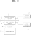
- FIG. 2 is an exemplary diagram briefly showing arrangement of a position sensor in the motor driven power steering system of a redundancy structure according to an embodiment of the present disclosure.
- the motor driven power steering system of a redundancy structure may include a driving motor 50, first and second power circuits 11 and 12, and first and second driving circuits 31 and 32, first and second position sensors 41 and 42, and first and second processors 21 and 22.
- the driving motor 50 may be a driving actuator of the motor driven power steering system, and substantially rotate and steer a steering wheel (not shown).
- the driving motor 50 may be a double winding motor that outputs one power but includes a first winding motor 51 and a second winding motor 52 therein, and have a redundancy structure in which the driving motor 50 is driven through control means independent from each other.
- the first winding motor 51 may be operatively coupled to the first power circuit 11, the first position sensor 41, the first driving circuit 31, and the first processor 21; and the second winding motor 52 may be operatively coupled to the second power circuit 12, the second position sensor 42, the second driving circuit 32, and the second processor 22.
- the first and second power circuits 11 and 12 may respectively supply control power and driving power to the first and second processors 21 and 22 and the first and second driving circuits 31 and 32, independently from each other.
- the first and second driving circuits 31 and 32 may respectively vary a frequency of the three-phase power supply based on control signals of the first and second processors 21 and 22 to adjust the speed and torque of the first winding motor 51 and the second winding motor 52 of the driving motor 50, thereby independently driving the driving motor 50.
- the first and second driving circuits 31 and 32 may each include at least one phase switch, including an inverter, which converts direct current (DC) driving power to the three-phase power supply, and at least one cut-off switch completely which cuts off the three-phase power supply when a failure occurs therein.
- phase switch including an inverter, which converts direct current (DC) driving power to the three-phase power supply, and at least one cut-off switch completely which cuts off the three-phase power supply when a failure occurs therein.
- phase switch and the cut-off switch may be a power semiconductor device such as a metal-oxide-semiconductor field-effect transistor (MOSFET)/insulated gate bipolar transistor (IGBT).
- MOSFET metal-oxide-semiconductor field-effect transistor
- IGBT insulated gate bipolar transistor
- the first and second position sensors 41 and 42 may each detect a rotational position of the driving motor 50 to output a position signal and a comparison signal, thereby comparing and verifying whether a measured value is normal.
- first and second position sensors 41 and 42 may be respectively mounted on positions corresponding to those of the lower surface and upper surface of one circuit board 60 as shown in FIG. 2 .
- first position sensor 41, the circuit board 60, and the second position sensor 42 may be sequentially arranged in a magnetic flux direction (i.e., z-axis direction) of a position detection magnet 55 positioned in the driving motor 50, and the first position sensor 41 and the second position sensor 42 may thus be robust against an external magnetic field.
- the first position sensor 41 may transmit, to the first processor 21, each of a first position signal for detecting position of the magnet 55 and a first comparison signal for monitoring and comparing whether the first position signal is normal; and the second position sensor 42 may transmit, to the second processor 22, each of a second position signal for detecting the position of the magnet 55 and a second comparison signal for monitoring and comparing whether the second position signal is normal.
- the first and second processors 21 and 22 may be operatively coupled to the driving motor 50, the first and second power circuits 11 and 12, the first and second position sensors 41 and 42, and the first and second driving circuits 31 and 32, respectively.
- the first processor 21 may receive a steering control signal from an upper-level control device to allow the first driving circuit 31 to be operated based on the first position sensor 41, thereby allowing the first winding motor 51 of the driving motor 50 to be operated.
- the second processor 22 may receive a steering control signal from the upper control device independently from the first processor 21 to allow the second driving circuit 32 to be operated based on the second position sensor 42, thereby allowing the second winding motor 52 of the driving motor 50 to be operated.
- the first processor 21 may stop its operation when a tolerance between the first position signal and the first comparison signal is out of a predetermined first reference error as a result of the comparison of the two signals; and the second processor 22 may stop its operation when a tolerance between the first position signal and the first comparison signal is out of a predetermined second reference error as a result of the comparison of the two signals.
- any one processor may allow the driving motor 50 to be operated to enable the steering unless the error occurs in both the first position sensor 41 and the second position sensor 42.
- the first reference error and the second reference error may be the same or different from each other based on a system environment.
- one processor may take a main control and allow the driving motor 50 to be operated while the first and second processors 21 and 22 monitor their mutual operation states, and the main control may be switched to the other processor when the error occurs, and the other processor may be driven to allow the driving motor 50 to be operated.
- the position sensor, driving circuit, processor, and power supply of the driving motor for redundant driving of the motor driven power steering system may each have the redundancy structure to be driven independently from each other, and the driving motor may thus be allowed to be operated by the other independent processor even when one processor fails, thereby securing stability of the processor and robustness of the position sensor against the external magnetic field.
- the implementation described herein may be implemented in, for example, a method or process, an apparatus, a software program, a data stream, or a signal. Although implementation is disclosed only in a single form (e.g., only as a method), the implementation of the disclosed feature may also be implemented in another form (e.g., as an apparatus or program).
- the apparatus may be implemented in suitable hardware, software, firmware, or the like.
- the method may be implemented in the apparatus such as a processor which generally refers to a computer, a micro-processor, a processing device including an integrated circuit, a programmable logic device or the like, etc.
- the processor may also include a communication device such as a computer, a mobile phone, a portable/personal digital assistant ("PDA") or another device, which facilitates communications of information between end-users.
- PDA portable/personal digital assistant
- the position sensor, driving circuit, processor, and power supply of the driving motor for the redundant driving of the motor driven power steering system may each have the redundancy structure to be driven independently from each other, and the driving motor may thus be allowed to be operated by the other independent processor even when one processor fails, thereby securing the stability of the processor and the robustness of the position sensor against the external magnetic field.
Landscapes
- Engineering & Computer Science (AREA)
- Chemical & Material Sciences (AREA)
- Combustion & Propulsion (AREA)
- Transportation (AREA)
- Mechanical Engineering (AREA)
- Power Engineering (AREA)
- Power Steering Mechanism (AREA)
Abstract
Description
- Embodiments of the present disclosure relate to a motor driven power steering system of a redundancy structure, and more particularly, to a motor driven power steering system of a redundancy structure in which a driving motor for redundant driving of the motor driven power steering system is independently controlled through a redundant circuit.
- In general, a motor driven power steering system (MDPS) may provide auxiliary torque in a direction in which a driver of a vehicle steers a wheel by using an electric motor, thereby making the driver's wheel handling lighter.
- Unlike a conventional hydraulic power steering (HPS) system, the motor driven power steering system may have improved steering performance and steering feel by automatically controlling an operation of the electric motor based on a driving condition of the vehicle.
- Here, the motor driven power steering system may determine the driving condition of the vehicle by including a torque sensor that measures the driver's steering torque input to the steering wheel, a steering angle sensor that measures a steering angle of the steering wheel, and a vehicle speed sensor that measures a vehicle speed.
- As such, the motor driven power steering system may be a major system that greatly affects steering safety of the vehicle, and reliable and safe driving of the motor driven power steering system may be an essential element for a safe operation of the vehicle.
- A driving motor used in the motor driven power steering system may include a direct current (DC) motor or an alternating current (AC) motor. In case of a conventional three-phase brushless AC motor, a study on a double winding motor to which double winding is applied is being actively conducted for a more reliable operation of the driving motor.
- The double winding motor may include two or more power supplies, and may be a motor designed to drive the motor only by inputting power to the remaining power supply even if a motor element or motor winding connected to any one of the two or more power supplies fails or breaks.
- Meanwhile, the double winding motor may implement a redundancy structure of the motor, thereby improving the safe and reliable driving of the motor.
- Therefore, there has been a need to improve the safe and reliable driving of the motor through the redundancy structure by applying such a double winding structure even to the driving motor used in the motor driven power steering system.
- Background technology of the present disclosure is disclosed in
Korea Patent Laid-Open Publication No. 10-2020-0091651 (published on July 31, 2020 - A motor driven power steering system may drive various actuators centered on an electronic control device, and thus require an independent redundancy structure as a demand for its safety and reliability further increases due to arrival of an autonomous driving era.
- Various embodiments are directed to a motor driven power steering system of a redundancy structure in which the position sensor, driving circuit, processor, and power supply of a driving motor for redundant driving of the motor driven power steering system each have the redundancy structure to be driven independently from each other.
- In an embodiment, a motor driven power steering system of a redundancy structure includes: a driving motor driving a steering wheel; first and second power circuits supplying control power; first and second driving circuits driving the driving motor; first and second position sensors detecting a rotational position of the driving motor; and first and second processors operatively coupled to the driving motor, the first and second power circuits, the first and second position sensors, and the first and second driving circuits, respectively, wherein the first processor receives a steering control signal from an upper-level control device to allow the first driving circuit to be operated based on the first position sensor, thereby allowing the driving motor to be operated, and the second processor receives a steering control signal from the upper-level control device to allow the second driving circuit to be operated based on the second position sensor, thereby allowing the driving motor to be operated.
- The first position sensor and the second position sensor may respectively be mounted on positions corresponding to those of the lower surface and upper surface of one circuit board.
- The first position sensor, the circuit board, and the second position sensor may be sequentially arranged in one magnetic flux direction of a position detection magnet positioned in the driving motor.
- The first position sensor may transmit each of a first position signal and a first comparison signal to the first processor, and the second position sensor may transmit each of a second position signal and a second comparison signal to the second processor.
- The first processor may stop its operation when a tolerance between the first position signal and the first comparison signal is out of a predetermined first reference error as a result of comparison of the two signals, and the second processor may stop its operation when a tolerance between the first position signal and the first comparison signal two signals is out of a predetermined second reference error as a result of comparison of the two signals.
- The driving motor may be a double winding motor including a first winding motor and a second winding motor.
- The first winding motor may be operatively coupled to the first power circuit, the first position sensor, the first driving circuit, and the first processor, and the second winding motor may be operatively coupled to the second power circuit, the second position sensor, the second driving circuit, and the second processor.
- One processor may take a main control and allow the driving motor to be operated while the first and second processors monitor their mutual operation states, and the main control may be switched to the other processor when the error occurs, and the other processor may allow the driving motor to be operated.
- The first and second driving circuits may each include at least one phase switch converting direct current (DC) driving power to a three-phase power supply, and at least one cut-off switch completely cutting off the three-phase power supply when a failure occurs therein.
- In an embodiment, a motor driven power steering system of a redundancy structure includes: a driving motor driving a steering wheel; first and second driving circuits driving the driving motor; first and second position sensors detecting a rotational position of the driving motor; a first processor; and a second processor, wherein the first processor receives a steering control signal from an upper-level control device to allow the first driving circuit to be operated based on the first position sensor, thereby allowing the driving motor to be operated, and the second processor receives a steering control signal from the upper-level control device to allow operate the second driving circuit be operated based on the second position sensor, thereby allowing the driving motor to be operated.
- The first position sensor and the second position sensor may respectively be mounted on positions corresponding to those of the lower surface and upper surface of one circuit board.
- The first position sensor, the circuit board, and the second position sensor may be sequentially arranged in one magnetic flux direction of a position detection magnet positioned in the driving motor.
- The first position sensor may transmit each of a first position signal and a first comparison signal to the first processor, the second position sensor may transmit each of a second position signal and a second comparison signal to the second processor, the first processor may stop its operation when a tolerance between the first position signal and the first comparison signal is out of a predetermined first reference error as a result of comparison of the two signals, and the second processor may stop its operation when a tolerance between the first position signal and the first comparison signal is out of a predetermined second reference error as a result of comparison of the two signals.
- The driving motor may be a double winding motor including a first winding motor and a second winding motor, the first winding motor may be operatively coupled to the first position sensor, the first driving circuit, and the first processor, and the second winding motor may be operatively coupled to the second position sensor, the second driving circuit, and the second processor.
- One processor may take a main control and allow the driving motor to be operated while the first and second processors monitor their mutual operation states, and the main control may be switched to the other processor when the error occurs, and the other processor may allow the driving motor to be operated.
-
-
FIG. 1 is a block diagram showing a motor driven power steering system of a redundancy structure according to an embodiment of the present disclosure. -
FIG. 2 is an exemplary diagram briefly showing arrangement of a position sensor in the motor driven power steering system of a redundancy structure according to an embodiment of the present disclosure. - As is traditional in the corresponding field, some exemplary embodiments may be illustrated in the drawings in terms of functional blocks, units, and/or modules. Those of ordinary skill in the art will appreciate that these block, units, and/or modules are physically implemented by electronic (or optical) circuits such as logic circuits, discrete components, processors, hard-wired circuits, memory elements, wiring connections, and the like. When the blocks, units, and/or modules are implemented by processors or similar hardware, they may be programmed and controlled using software (e.g., code) to perform various functions discussed herein. Alternatively, each block, unit, and/or module may be implemented by dedicated hardware or as a combination of dedicated hardware to perform some functions and a processor (e.g., one or more programmed processors and associated circuitry) to perform other functions. Each block, unit, and/or module of some exemplary embodiments may be physically separated into two or more interacting and discrete blocks, units, and/or modules without departing from the scope of the inventive concept. Further, blocks, units, and/or module of some exemplary embodiments may be physically combined into more complex blocks, units, and/or modules without departing from the scope of the inventive concept.
- The embodiments described in this specification may be implemented with a method or process, a device, a software program, a data stream or a signal, for example. Although a feature is discussed only in a single context (for example, discussed only in a method), the discussed feature can be implemented in another type (for example, apparatus or program). An apparatus may be implemented in suitable hardware, software or firmware. The method can be implemented in a device such as a processor which generally refers to a processing device including a computer, a microprocessor, an integrated circuit or a programmable logic device. The processor also includes a communication device, such as a computer, cellular phone, PDA (Personal Digital Assistant) and another device, which facilitates information communication between end users.Hereinafter, a motor driven power steering system of a redundancy structure will be described below with reference to the accompanying drawings through various embodiments.
-
FIG. 1 is a block diagram showing a motor driven power steering system of a redundancy structure according to an embodiment of the present disclosure; andFIG. 2 is an exemplary diagram briefly showing arrangement of a position sensor in the motor driven power steering system of a redundancy structure according to an embodiment of the present disclosure. - As shown in
FIG. 1 , the motor driven power steering system of a redundancy structure according to an embodiment of the present disclosure may include adriving motor 50, first andsecond power circuits second driving circuits second position sensors second processors - The
driving motor 50 may be a driving actuator of the motor driven power steering system, and substantially rotate and steer a steering wheel (not shown). - Here, the
driving motor 50 may be a double winding motor that outputs one power but includes a first windingmotor 51 and a second windingmotor 52 therein, and have a redundancy structure in which the drivingmotor 50 is driven through control means independent from each other. - Accordingly, the
first winding motor 51 may be operatively coupled to thefirst power circuit 11, thefirst position sensor 41, thefirst driving circuit 31, and thefirst processor 21; and thesecond winding motor 52 may be operatively coupled to thesecond power circuit 12, thesecond position sensor 42, thesecond driving circuit 32, and thesecond processor 22. - The first and
second power circuits second processors second driving circuits - The first and
second driving circuits second processors motor 51 and the second windingmotor 52 of thedriving motor 50, thereby independently driving thedriving motor 50. - Here, the first and
second driving circuits - In this case, the phase switch and the cut-off switch may be a power semiconductor device such as a metal-oxide-semiconductor field-effect transistor (MOSFET)/insulated gate bipolar transistor (IGBT).
- The first and
second position sensors motor 50 to output a position signal and a comparison signal, thereby comparing and verifying whether a measured value is normal. - Here, the first and
second position sensors circuit board 60 as shown inFIG. 2 . - Here, the
first position sensor 41, thecircuit board 60, and thesecond position sensor 42 may be sequentially arranged in a magnetic flux direction (i.e., z-axis direction) of aposition detection magnet 55 positioned in thedriving motor 50, and thefirst position sensor 41 and thesecond position sensor 42 may thus be robust against an external magnetic field. - Accordingly, the
first position sensor 41 may transmit, to thefirst processor 21, each of a first position signal for detecting position of themagnet 55 and a first comparison signal for monitoring and comparing whether the first position signal is normal; and thesecond position sensor 42 may transmit, to thesecond processor 22, each of a second position signal for detecting the position of themagnet 55 and a second comparison signal for monitoring and comparing whether the second position signal is normal. - The first and
second processors motor 50, the first andsecond power circuits second position sensors second driving circuits - Accordingly, the
first processor 21 may receive a steering control signal from an upper-level control device to allow thefirst driving circuit 31 to be operated based on thefirst position sensor 41, thereby allowing the first windingmotor 51 of thedriving motor 50 to be operated. - In addition, the
second processor 22 may receive a steering control signal from the upper control device independently from thefirst processor 21 to allow thesecond driving circuit 32 to be operated based on thesecond position sensor 42, thereby allowing thesecond winding motor 52 of thedriving motor 50 to be operated. - Here, the
first processor 21 may stop its operation when a tolerance between the first position signal and the first comparison signal is out of a predetermined first reference error as a result of the comparison of the two signals; and thesecond processor 22 may stop its operation when a tolerance between the first position signal and the first comparison signal is out of a predetermined second reference error as a result of the comparison of the two signals. Accordingly, any one processor may allow thedriving motor 50 to be operated to enable the steering unless the error occurs in both thefirst position sensor 41 and thesecond position sensor 42. The first reference error and the second reference error may be the same or different from each other based on a system environment. - Meanwhile, one processor may take a main control and allow the driving
motor 50 to be operated while the first andsecond processors motor 50 to be operated. - As described above, according to the motor driven power steering system of a redundancy structure according to an embodiment of the present disclosure, the position sensor, driving circuit, processor, and power supply of the driving motor for redundant driving of the motor driven power steering system may each have the redundancy structure to be driven independently from each other, and the driving motor may thus be allowed to be operated by the other independent processor even when one processor fails, thereby securing stability of the processor and robustness of the position sensor against the external magnetic field.
- The implementation described herein may be implemented in, for example, a method or process, an apparatus, a software program, a data stream, or a signal. Although implementation is disclosed only in a single form (e.g., only as a method), the implementation of the disclosed feature may also be implemented in another form (e.g., as an apparatus or program). The apparatus may be implemented in suitable hardware, software, firmware, or the like. For example, the method may be implemented in the apparatus such as a processor which generally refers to a computer, a micro-processor, a processing device including an integrated circuit, a programmable logic device or the like, etc. The processor may also include a communication device such as a computer, a mobile phone, a portable/personal digital assistant ("PDA") or another device, which facilitates communications of information between end-users.
- As set forth above, according to the motor driven power steering system of a redundancy structure according to the embodiments of the present disclosure, the position sensor, driving circuit, processor, and power supply of the driving motor for the redundant driving of the motor driven power steering system may each have the redundancy structure to be driven independently from each other, and the driving motor may thus be allowed to be operated by the other independent processor even when one processor fails, thereby securing the stability of the processor and the robustness of the position sensor against the external magnetic field.
Claims (15)
- A motor driven power steering system of a redundancy structure, the system comprising:a driving motor configured to drive a steering wheel;first and second power circuits configured to supply control power;first and second driving circuits configured to drive the driving motor;first and second position sensors configured to detect a rotational position of the driving motor; andfirst and second processors operatively coupled to the driving motor, the first and second power circuits, the first and second position sensors, and the first and second driving circuits, respectively,wherein the first processor is configured to receive a steering control signal from an upper-level control device to allow the first driving circuit to be operated based on the first position sensor, thereby allowing the driving motor to be operated, andthe second processor is configured to receive a steering control signal from the upper-level control device to allow the second driving circuit to be operated based on the second position sensor, thereby allowing the driving motor to be operated.
- The system of claim 1, wherein the first position sensor and the second position sensor are respectively mounted on positions corresponding to those of the lower surface and upper surface of one circuit board.
- The system of claim 2, wherein the first position sensor, the circuit board, and the second position sensor are sequentially arranged in one magnetic flux direction of a position detection magnet positioned in the driving motor.
- The system of any one of claims 1 to 3, wherein the first position sensor is configured to transmit each of a first position signal and a first comparison signal to the first processor, and
the second position sensor is configured to transmit each of a second position signal and a second comparison signal to the second processor. - The system of claim 4, wherein the first processor is configured to stop its operation when a tolerance between the first position signal and the first comparison signal is out of a predetermined first reference error as a result of comparison of the two signals, and
the second processor is configured to stop its operation when a tolerance between the first position signal and the first comparison signal is out of a predetermined second reference error as a result of comparison of the two signals. - The system of any one of claims 1 to 5, wherein the driving motor is a double winding motor including a first winding motor and a second winding motor.
- The system of claim 6, wherein the first winding motor is operatively coupled to the first power circuit, the first position sensor, the first driving circuit, and the first processor, and
the second winding motor is operatively coupled to the second power circuit, the second position sensor, the second driving circuit, and the second processor. - The system of any one of claims 1 to 7, wherein one processor is configured to take a main control and allow the driving motor to be operated while the first and second processors monitor their mutual operation states, and the main control is switched to the other processor when the error occurs, and the other processor is configured to allow the driving motor to be operated.
- The system of any one of claims 1 to 8, wherein the first and second driving circuits each include at least one phase switch configured to convert direct current (DC) driving power to a three-phase power supply, and at least one cut-off switch configured to completely cut off the three-phase power supply when a failure occurs therein.
- A motor driven power steering system of a redundancy structure, the system comprising:a driving motor configured to drive a steering wheel;first and second driving circuits configured to drive the driving motor;first and second position sensors configured to detect a rotational position of the driving motor;a first processor; anda second processor,wherein the first processor is configured to receive a steering control signal from an upper-level control device to allow the first driving circuit to be operated based on the first position sensor, thereby allowing the driving motor to be operated, andthe second processor is configured to receive a steering control signal from the upper-level control device to allow operate the second driving circuit be operated based on the second position sensor, thereby allowing the driving motor to be operated.
- The system of claim 10, wherein the first position sensor and the second position sensor are respectively mounted on positions corresponding to those of the lower surface and upper surface of one circuit board.
- The system of claim 11, wherein the first position sensor, the circuit board, and the second position sensor are sequentially arranged in one magnetic flux direction of a position detection magnet positioned in the driving motor.
- The system of any one of claims 10 to 12, wherein the first position sensor is configured to transmit each of a first position signal and a first comparison signal to the first processor,the second position sensor is configured to transmit each of a second position signal and a second comparison signal to the second processor,the first processor is configured to stop its operation when a tolerance between the first position signal and the first comparison signal is out of a predetermined first reference error as a result of comparison of the two signals, andthe second processor is configured to stop its operation when a tolerance between the first position signal and the first comparison signal is out of a predetermined second reference error as a result of comparison of the two signals.
- The system of any one of claims 10 to 13, wherein the driving motor is a double winding motor including a first winding motor and a second winding motor,the first winding motor is operatively coupled to the first position sensor, the first driving circuit, and the first processor, andthe second winding motor is operatively coupled to the second position sensor, the second driving circuit, and the second processor.
- The system of any one of claims 10 to 14, wherein one processor is configured to take a main control and allow a main control and allows the driving motor to be operated while the first and second processors monitor their mutual operation states, and the main control is switched to the other processor when the error occurs, and the other processor is configured to allow the driving motor to be operated.
Applications Claiming Priority (1)
| Application Number | Priority Date | Filing Date | Title |
|---|---|---|---|
| KR1020220103311A KR20240025280A (en) | 2022-08-18 | 2022-08-18 | Motor driven power steering apparatus of redundancy structure |
Publications (2)
| Publication Number | Publication Date |
|---|---|
| EP4324724A1 true EP4324724A1 (en) | 2024-02-21 |
| EP4324724B1 EP4324724B1 (en) | 2025-09-10 |
Family
ID=84389113
Family Applications (1)
| Application Number | Title | Priority Date | Filing Date |
|---|---|---|---|
| EP22211406.8A Active EP4324724B1 (en) | 2022-08-18 | 2022-12-05 | Motor driven power steering system of redundancy structure |
Country Status (4)
| Country | Link |
|---|---|
| US (1) | US12565261B2 (en) |
| EP (1) | EP4324724B1 (en) |
| KR (1) | KR20240025280A (en) |
| CN (1) | CN117585054A (en) |
Citations (3)
| Publication number | Priority date | Publication date | Assignee | Title |
|---|---|---|---|---|
| EP3466795A1 (en) * | 2016-05-24 | 2019-04-10 | Mitsubishi Electric Corporation | Electronic control device and operation control method therefor |
| KR20200091651A (en) | 2019-01-23 | 2020-07-31 | 주식회사 만도 | Redundancy circuit for electric power steering system |
| US20200353975A1 (en) * | 2019-05-07 | 2020-11-12 | Denso Corporation | Rotary electric machine control device and method |
Family Cites Families (7)
| Publication number | Priority date | Publication date | Assignee | Title |
|---|---|---|---|---|
| JP6078444B2 (en) * | 2013-09-20 | 2017-02-08 | 日立オートモティブシステムズ株式会社 | Power steering device and control device for on-vehicle equipment |
| DE102015222266A1 (en) * | 2015-11-11 | 2017-05-11 | Robert Bosch Automotive Steering Gmbh | Electromechanical actuator with redundant electronic subsystem |
| JP6685427B2 (en) * | 2016-11-16 | 2020-04-22 | 三菱電機株式会社 | Rotating electric machine control device, and electric power steering apparatus including the rotating electric machine control device |
| KR102004720B1 (en) | 2017-10-24 | 2019-07-29 | 주식회사 만도 | Apparatus of electronic power steering having redundancy for safety enhancement |
| KR102086432B1 (en) * | 2018-08-23 | 2020-03-09 | 주식회사 만도 | Steering apparatus for vehicle |
| KR102487001B1 (en) * | 2019-07-22 | 2023-01-10 | 에이치엘만도 주식회사 | System and Apparatus for assisting power of steering |
| KR102884614B1 (en) | 2020-01-16 | 2025-11-12 | 엘지이노텍 주식회사 | Rotor position sensing apparatus and method thereof |
-
2022
- 2022-08-18 KR KR1020220103311A patent/KR20240025280A/en not_active Ceased
- 2022-11-30 US US18/071,721 patent/US12565261B2/en active Active
- 2022-12-05 EP EP22211406.8A patent/EP4324724B1/en active Active
- 2022-12-15 CN CN202211615600.XA patent/CN117585054A/en active Pending
Patent Citations (3)
| Publication number | Priority date | Publication date | Assignee | Title |
|---|---|---|---|---|
| EP3466795A1 (en) * | 2016-05-24 | 2019-04-10 | Mitsubishi Electric Corporation | Electronic control device and operation control method therefor |
| KR20200091651A (en) | 2019-01-23 | 2020-07-31 | 주식회사 만도 | Redundancy circuit for electric power steering system |
| US20200353975A1 (en) * | 2019-05-07 | 2020-11-12 | Denso Corporation | Rotary electric machine control device and method |
Also Published As
| Publication number | Publication date |
|---|---|
| CN117585054A (en) | 2024-02-23 |
| US20240059349A1 (en) | 2024-02-22 |
| KR20240025280A (en) | 2024-02-27 |
| EP4324724B1 (en) | 2025-09-10 |
| US12565261B2 (en) | 2026-03-03 |
Similar Documents
| Publication | Publication Date | Title |
|---|---|---|
| US20110205672A1 (en) | Motor controller and electric power steering device | |
| JP5621598B2 (en) | Motor control device and electric power steering device | |
| JP6593508B2 (en) | Motor control device and electric power steering device equipped with the same | |
| US11489480B2 (en) | Apparatus for driving motor of motor driven power steering and control method thereof | |
| KR101011912B1 (en) | Steering control unit | |
| CN110417314B (en) | Motor control device and electric power steering device | |
| CN107592845A (en) | Electromechanical power steering | |
| US8037964B2 (en) | Electric power steering apparatus | |
| KR102487001B1 (en) | System and Apparatus for assisting power of steering | |
| US9932067B2 (en) | Electric power steering apparatus | |
| CN109195859B (en) | Electronic control device and operation control method thereof | |
| US20080017439A1 (en) | Power steering apparatus | |
| JP2018043578A (en) | Sensor device | |
| CN117044095A (en) | Power conversion device | |
| EP4324724B1 (en) | Motor driven power steering system of redundancy structure | |
| KR20210112539A (en) | Motor driven power steering apparatus of redundancy structure | |
| KR20160119311A (en) | Electronic control apparatus and method for | |
| KR20220046917A (en) | Redundant operating apparatus of motor driven power steering system | |
| KR102700915B1 (en) | Apparatus and method for controlling phase current of motor in motor driven power steering | |
| KR20220163107A (en) | Apparatus and method for controlling redundacy motor | |
| CN112109800A (en) | Redundant Electronic Steering System | |
| KR102864689B1 (en) | Motor control system and control method thereof | |
| JP7581982B2 (en) | MOTOR CONTROL DEVICE AND METHOD FOR ADJUSTING COMMUNICATION ENVIRONMENT IN MOTOR CONTROL DEVICE | |
| JP2014117064A (en) | Motor controller | |
| JP2004312931A (en) | Abnormality detection device and abnormality detection method for motor control arithmetic unit |
Legal Events
| Date | Code | Title | Description |
|---|---|---|---|
| PUAI | Public reference made under article 153(3) epc to a published international application that has entered the european phase |
Free format text: ORIGINAL CODE: 0009012 |
|
| STAA | Information on the status of an ep patent application or granted ep patent |
Free format text: STATUS: REQUEST FOR EXAMINATION WAS MADE |
|
| 17P | Request for examination filed |
Effective date: 20221205 |
|
| AK | Designated contracting states |
Kind code of ref document: A1 Designated state(s): AL AT BE BG CH CY CZ DE DK EE ES FI FR GB GR HR HU IE IS IT LI LT LU LV MC ME MK MT NL NO PL PT RO RS SE SI SK SM TR |
|
| STAA | Information on the status of an ep patent application or granted ep patent |
Free format text: STATUS: EXAMINATION IS IN PROGRESS |
|
| 17Q | First examination report despatched |
Effective date: 20241106 |
|
| GRAP | Despatch of communication of intention to grant a patent |
Free format text: ORIGINAL CODE: EPIDOSNIGR1 |
|
| STAA | Information on the status of an ep patent application or granted ep patent |
Free format text: STATUS: GRANT OF PATENT IS INTENDED |
|
| INTG | Intention to grant announced |
Effective date: 20250409 |
|
| P01 | Opt-out of the competence of the unified patent court (upc) registered |
Free format text: CASE NUMBER: APP_22293/2025 Effective date: 20250512 |
|
| GRAS | Grant fee paid |
Free format text: ORIGINAL CODE: EPIDOSNIGR3 |
|
| GRAA | (expected) grant |
Free format text: ORIGINAL CODE: 0009210 |
|
| STAA | Information on the status of an ep patent application or granted ep patent |
Free format text: STATUS: THE PATENT HAS BEEN GRANTED |
|
| AK | Designated contracting states |
Kind code of ref document: B1 Designated state(s): AL AT BE BG CH CY CZ DE DK EE ES FI FR GB GR HR HU IE IS IT LI LT LU LV MC ME MK MT NL NO PL PT RO RS SE SI SK SM TR |
|
| REG | Reference to a national code |
Ref country code: GB Ref legal event code: FG4D |
|
| REG | Reference to a national code |
Ref country code: CH Ref legal event code: EP |
|
| REG | Reference to a national code |
Ref country code: DE Ref legal event code: R096 Ref document number: 602022021132 Country of ref document: DE |
|
| REG | Reference to a national code |
Ref country code: IE Ref legal event code: FG4D |
|
| PG25 | Lapsed in a contracting state [announced via postgrant information from national office to epo] |
Ref country code: NO Free format text: LAPSE BECAUSE OF FAILURE TO SUBMIT A TRANSLATION OF THE DESCRIPTION OR TO PAY THE FEE WITHIN THE PRESCRIBED TIME-LIMIT Effective date: 20251210 |
|
| REG | Reference to a national code |
Ref country code: LT Ref legal event code: MG9D |
|
| PGFP | Annual fee paid to national office [announced via postgrant information from national office to epo] |
Ref country code: AT Payment date: 20260113 Year of fee payment: 4 |
|
| PG25 | Lapsed in a contracting state [announced via postgrant information from national office to epo] |
Ref country code: FI Free format text: LAPSE BECAUSE OF FAILURE TO SUBMIT A TRANSLATION OF THE DESCRIPTION OR TO PAY THE FEE WITHIN THE PRESCRIBED TIME-LIMIT Effective date: 20250910 |
|
| REG | Reference to a national code |
Ref country code: NL Ref legal event code: MP Effective date: 20250910 |
|
| PG25 | Lapsed in a contracting state [announced via postgrant information from national office to epo] |
Ref country code: HR Free format text: LAPSE BECAUSE OF FAILURE TO SUBMIT A TRANSLATION OF THE DESCRIPTION OR TO PAY THE FEE WITHIN THE PRESCRIBED TIME-LIMIT Effective date: 20250910 |
|
| PGFP | Annual fee paid to national office [announced via postgrant information from national office to epo] |
Ref country code: FR Payment date: 20251217 Year of fee payment: 4 |
|
| PG25 | Lapsed in a contracting state [announced via postgrant information from national office to epo] |
Ref country code: GR Free format text: LAPSE BECAUSE OF FAILURE TO SUBMIT A TRANSLATION OF THE DESCRIPTION OR TO PAY THE FEE WITHIN THE PRESCRIBED TIME-LIMIT Effective date: 20251211 |
|
| PG25 | Lapsed in a contracting state [announced via postgrant information from national office to epo] |
Ref country code: SE Free format text: LAPSE BECAUSE OF FAILURE TO SUBMIT A TRANSLATION OF THE DESCRIPTION OR TO PAY THE FEE WITHIN THE PRESCRIBED TIME-LIMIT Effective date: 20250910 |
|
| PG25 | Lapsed in a contracting state [announced via postgrant information from national office to epo] |
Ref country code: LV Free format text: LAPSE BECAUSE OF FAILURE TO SUBMIT A TRANSLATION OF THE DESCRIPTION OR TO PAY THE FEE WITHIN THE PRESCRIBED TIME-LIMIT Effective date: 20250910 |
|
| PG25 | Lapsed in a contracting state [announced via postgrant information from national office to epo] |
Ref country code: PL Free format text: LAPSE BECAUSE OF FAILURE TO SUBMIT A TRANSLATION OF THE DESCRIPTION OR TO PAY THE FEE WITHIN THE PRESCRIBED TIME-LIMIT Effective date: 20250910 Ref country code: BG Free format text: LAPSE BECAUSE OF FAILURE TO SUBMIT A TRANSLATION OF THE DESCRIPTION OR TO PAY THE FEE WITHIN THE PRESCRIBED TIME-LIMIT Effective date: 20250910 |
|
| PG25 | Lapsed in a contracting state [announced via postgrant information from national office to epo] |
Ref country code: RS Free format text: LAPSE BECAUSE OF FAILURE TO SUBMIT A TRANSLATION OF THE DESCRIPTION OR TO PAY THE FEE WITHIN THE PRESCRIBED TIME-LIMIT Effective date: 20251210 |
|
| PG25 | Lapsed in a contracting state [announced via postgrant information from national office to epo] |
Ref country code: ES Free format text: LAPSE BECAUSE OF FAILURE TO SUBMIT A TRANSLATION OF THE DESCRIPTION OR TO PAY THE FEE WITHIN THE PRESCRIBED TIME-LIMIT Effective date: 20250910 |
|
| REG | Reference to a national code |
Ref country code: AT Ref legal event code: MK05 Ref document number: 1835625 Country of ref document: AT Kind code of ref document: T Effective date: 20250910 |
|
| PG25 | Lapsed in a contracting state [announced via postgrant information from national office to epo] |
Ref country code: NL Free format text: LAPSE BECAUSE OF FAILURE TO SUBMIT A TRANSLATION OF THE DESCRIPTION OR TO PAY THE FEE WITHIN THE PRESCRIBED TIME-LIMIT Effective date: 20250910 |
|
| PG25 | Lapsed in a contracting state [announced via postgrant information from national office to epo] |
Ref country code: SM Free format text: LAPSE BECAUSE OF FAILURE TO SUBMIT A TRANSLATION OF THE DESCRIPTION OR TO PAY THE FEE WITHIN THE PRESCRIBED TIME-LIMIT Effective date: 20250910 |
|
| PGFP | Annual fee paid to national office [announced via postgrant information from national office to epo] |
Ref country code: DE Payment date: 20251222 Year of fee payment: 4 |
|
| PG25 | Lapsed in a contracting state [announced via postgrant information from national office to epo] |
Ref country code: AT Free format text: LAPSE BECAUSE OF FAILURE TO SUBMIT A TRANSLATION OF THE DESCRIPTION OR TO PAY THE FEE WITHIN THE PRESCRIBED TIME-LIMIT Effective date: 20250910 |
|
| PG25 | Lapsed in a contracting state [announced via postgrant information from national office to epo] |
Ref country code: IT Free format text: LAPSE BECAUSE OF FAILURE TO SUBMIT A TRANSLATION OF THE DESCRIPTION OR TO PAY THE FEE WITHIN THE PRESCRIBED TIME-LIMIT Effective date: 20250910 Ref country code: RO Free format text: LAPSE BECAUSE OF FAILURE TO SUBMIT A TRANSLATION OF THE DESCRIPTION OR TO PAY THE FEE WITHIN THE PRESCRIBED TIME-LIMIT Effective date: 20250910 |
|
| PG25 | Lapsed in a contracting state [announced via postgrant information from national office to epo] |
Ref country code: IS Free format text: LAPSE BECAUSE OF FAILURE TO SUBMIT A TRANSLATION OF THE DESCRIPTION OR TO PAY THE FEE WITHIN THE PRESCRIBED TIME-LIMIT Effective date: 20260110 |
|
| PG25 | Lapsed in a contracting state [announced via postgrant information from national office to epo] |
Ref country code: PT Free format text: LAPSE BECAUSE OF FAILURE TO SUBMIT A TRANSLATION OF THE DESCRIPTION OR TO PAY THE FEE WITHIN THE PRESCRIBED TIME-LIMIT Effective date: 20260112 Ref country code: CZ Free format text: LAPSE BECAUSE OF FAILURE TO SUBMIT A TRANSLATION OF THE DESCRIPTION OR TO PAY THE FEE WITHIN THE PRESCRIBED TIME-LIMIT Effective date: 20250910 |
|
| PG25 | Lapsed in a contracting state [announced via postgrant information from national office to epo] |
Ref country code: EE Free format text: LAPSE BECAUSE OF FAILURE TO SUBMIT A TRANSLATION OF THE DESCRIPTION OR TO PAY THE FEE WITHIN THE PRESCRIBED TIME-LIMIT Effective date: 20250910 Ref country code: SK Free format text: LAPSE BECAUSE OF FAILURE TO SUBMIT A TRANSLATION OF THE DESCRIPTION OR TO PAY THE FEE WITHIN THE PRESCRIBED TIME-LIMIT Effective date: 20250910 |
|
| REG | Reference to a national code |
Ref country code: DE Ref legal event code: R097 Ref document number: 602022021132 Country of ref document: DE |
|
| PG25 | Lapsed in a contracting state [announced via postgrant information from national office to epo] |
Ref country code: LT Free format text: LAPSE BECAUSE OF FAILURE TO SUBMIT A TRANSLATION OF THE DESCRIPTION OR TO PAY THE FEE WITHIN THE PRESCRIBED TIME-LIMIT Effective date: 20250910 |
|
| PG25 | Lapsed in a contracting state [announced via postgrant information from national office to epo] |
Ref country code: MC Free format text: LAPSE BECAUSE OF FAILURE TO SUBMIT A TRANSLATION OF THE DESCRIPTION OR TO PAY THE FEE WITHIN THE PRESCRIBED TIME-LIMIT Effective date: 20250910 |
|
| PG25 | Lapsed in a contracting state [announced via postgrant information from national office to epo] |
Ref country code: DK Free format text: LAPSE BECAUSE OF FAILURE TO SUBMIT A TRANSLATION OF THE DESCRIPTION OR TO PAY THE FEE WITHIN THE PRESCRIBED TIME-LIMIT Effective date: 20250910 |
|
| PLBE | No opposition filed within time limit |
Free format text: ORIGINAL CODE: 0009261 |
|
| STAA | Information on the status of an ep patent application or granted ep patent |
Free format text: STATUS: NO OPPOSITION FILED WITHIN TIME LIMIT |
|
| REG | Reference to a national code |
Ref country code: CH Ref legal event code: L10 Free format text: ST27 STATUS EVENT CODE: U-0-0-L10-L00 (AS PROVIDED BY THE NATIONAL OFFICE) Effective date: 20260722 |
|
| REG | Reference to a national code |
Ref country code: CH Ref legal event code: H13 Free format text: ST27 STATUS EVENT CODE: U-0-0-H10-H13 (AS PROVIDED BY THE NATIONAL OFFICE) Effective date: 20260723 |