EP4324690A2 - Manual locking stud for aircraft seat - Google Patents
Manual locking stud for aircraft seat Download PDFInfo
- Publication number
- EP4324690A2 EP4324690A2 EP24150390.3A EP24150390A EP4324690A2 EP 4324690 A2 EP4324690 A2 EP 4324690A2 EP 24150390 A EP24150390 A EP 24150390A EP 4324690 A2 EP4324690 A2 EP 4324690A2
- Authority
- EP
- European Patent Office
- Prior art keywords
- track
- plunger
- pin member
- foot body
- various embodiments
- Prior art date
- Legal status (The legal status is an assumption and is not a legal conclusion. Google has not performed a legal analysis and makes no representation as to the accuracy of the status listed.)
- Granted
Links
Images





Classifications
-
- B—PERFORMING OPERATIONS; TRANSPORTING
- B64—AIRCRAFT; AVIATION; COSMONAUTICS
- B64D—EQUIPMENT FOR FITTING IN OR TO AIRCRAFT; FLIGHT SUITS; PARACHUTES; ARRANGEMENT OR MOUNTING OF POWER PLANTS OR PROPULSION TRANSMISSIONS IN AIRCRAFT
- B64D11/00—Passenger or crew accommodation; Flight-deck installations not otherwise provided for
- B64D11/06—Arrangements of seats, or adaptations or details specially adapted for aircraft seats
- B64D11/0696—Means for fastening seats to floors, e.g. to floor rails
-
- B—PERFORMING OPERATIONS; TRANSPORTING
- B64—AIRCRAFT; AVIATION; COSMONAUTICS
- B64D—EQUIPMENT FOR FITTING IN OR TO AIRCRAFT; FLIGHT SUITS; PARACHUTES; ARRANGEMENT OR MOUNTING OF POWER PLANTS OR PROPULSION TRANSMISSIONS IN AIRCRAFT
- B64D11/00—Passenger or crew accommodation; Flight-deck installations not otherwise provided for
- B64D11/06—Arrangements of seats, or adaptations or details specially adapted for aircraft seats
- B64D11/0648—Lower frame constructions
-
- B—PERFORMING OPERATIONS; TRANSPORTING
- B60—VEHICLES IN GENERAL
- B60N—SEATS SPECIALLY ADAPTED FOR VEHICLES; VEHICLE PASSENGER ACCOMMODATION NOT OTHERWISE PROVIDED FOR
- B60N2/00—Seats specially adapted for vehicles; Arrangement or mounting of seats in vehicles
- B60N2/005—Arrangement or mounting of seats in vehicles, e.g. dismountable auxiliary seats
- B60N2/015—Attaching seats directly to vehicle chassis
- B60N2/01508—Attaching seats directly to vehicle chassis using quick release attachments
- B60N2/01516—Attaching seats directly to vehicle chassis using quick release attachments with locking mechanisms
- B60N2/01558—Attaching seats directly to vehicle chassis using quick release attachments with locking mechanisms with key and slot
- B60N2/01575—Attaching seats directly to vehicle chassis using quick release attachments with locking mechanisms with key and slot key sliding inside the vehicle floor or rail
-
- B—PERFORMING OPERATIONS; TRANSPORTING
- B60—VEHICLES IN GENERAL
- B60N—SEATS SPECIALLY ADAPTED FOR VEHICLES; VEHICLE PASSENGER ACCOMMODATION NOT OTHERWISE PROVIDED FOR
- B60N2/00—Seats specially adapted for vehicles; Arrangement or mounting of seats in vehicles
- B60N2/02—Seats specially adapted for vehicles; Arrangement or mounting of seats in vehicles the seat or part thereof being movable, e.g. adjustable
- B60N2/04—Seats specially adapted for vehicles; Arrangement or mounting of seats in vehicles the seat or part thereof being movable, e.g. adjustable the whole seat being movable
- B60N2/06—Seats specially adapted for vehicles; Arrangement or mounting of seats in vehicles the seat or part thereof being movable, e.g. adjustable the whole seat being movable slidable
- B60N2/08—Seats specially adapted for vehicles; Arrangement or mounting of seats in vehicles the seat or part thereof being movable, e.g. adjustable the whole seat being movable slidable characterised by the locking device
- B60N2/0806—Seats specially adapted for vehicles; Arrangement or mounting of seats in vehicles the seat or part thereof being movable, e.g. adjustable the whole seat being movable slidable characterised by the locking device with pin alignment systems, e.g. with at least one of a plurality of locking pins always aligned w.r.t. at least one of a plurality of pin-receiving elements
-
- B—PERFORMING OPERATIONS; TRANSPORTING
- B60—VEHICLES IN GENERAL
- B60N—SEATS SPECIALLY ADAPTED FOR VEHICLES; VEHICLE PASSENGER ACCOMMODATION NOT OTHERWISE PROVIDED FOR
- B60N2/00—Seats specially adapted for vehicles; Arrangement or mounting of seats in vehicles
- B60N2/02—Seats specially adapted for vehicles; Arrangement or mounting of seats in vehicles the seat or part thereof being movable, e.g. adjustable
- B60N2/04—Seats specially adapted for vehicles; Arrangement or mounting of seats in vehicles the seat or part thereof being movable, e.g. adjustable the whole seat being movable
- B60N2/06—Seats specially adapted for vehicles; Arrangement or mounting of seats in vehicles the seat or part thereof being movable, e.g. adjustable the whole seat being movable slidable
- B60N2/08—Seats specially adapted for vehicles; Arrangement or mounting of seats in vehicles the seat or part thereof being movable, e.g. adjustable the whole seat being movable slidable characterised by the locking device
- B60N2/0812—Location of the latch
- B60N2/0818—Location of the latch inside the rail
-
- B—PERFORMING OPERATIONS; TRANSPORTING
- B60—VEHICLES IN GENERAL
- B60N—SEATS SPECIALLY ADAPTED FOR VEHICLES; VEHICLE PASSENGER ACCOMMODATION NOT OTHERWISE PROVIDED FOR
- B60N2/00—Seats specially adapted for vehicles; Arrangement or mounting of seats in vehicles
- B60N2/02—Seats specially adapted for vehicles; Arrangement or mounting of seats in vehicles the seat or part thereof being movable, e.g. adjustable
- B60N2/04—Seats specially adapted for vehicles; Arrangement or mounting of seats in vehicles the seat or part thereof being movable, e.g. adjustable the whole seat being movable
- B60N2/06—Seats specially adapted for vehicles; Arrangement or mounting of seats in vehicles the seat or part thereof being movable, e.g. adjustable the whole seat being movable slidable
- B60N2/07—Slide construction
- B60N2/0702—Slide construction characterised by its cross-section
- B60N2/0715—C or U-shaped
-
- B—PERFORMING OPERATIONS; TRANSPORTING
- B60—VEHICLES IN GENERAL
- B60N—SEATS SPECIALLY ADAPTED FOR VEHICLES; VEHICLE PASSENGER ACCOMMODATION NOT OTHERWISE PROVIDED FOR
- B60N2/00—Seats specially adapted for vehicles; Arrangement or mounting of seats in vehicles
- B60N2/02—Seats specially adapted for vehicles; Arrangement or mounting of seats in vehicles the seat or part thereof being movable, e.g. adjustable
- B60N2/04—Seats specially adapted for vehicles; Arrangement or mounting of seats in vehicles the seat or part thereof being movable, e.g. adjustable the whole seat being movable
- B60N2/06—Seats specially adapted for vehicles; Arrangement or mounting of seats in vehicles the seat or part thereof being movable, e.g. adjustable the whole seat being movable slidable
- B60N2/07—Slide construction
- B60N2/0722—Constructive details
- B60N2/0732—Attachment of seat frame to the slide, e.g. eyelets
Definitions
- the present disclosure relates generally to seating assemblies for aircraft and, more particularly, to track fitting locking stud devices used for securing a seating assembly to an aircraft.
- the mechanism generally includes a pin or bolt that extends into the longitudinal track.
- a tight fit between the pin or bolt and a locking feature may be difficult to maintain over time or following repeated use, or may be intentionally avoided by design for ease of installation.
- a loose fit between the pin or bolt and the locking feature may result in undesirable play or movement within a joint formed by the mechanism and the longitudinal track.
- tools such as wrenches or screwdrivers.
- the seat assembly includes a seat frame, a track assembly and a track lock assembly slidably connecting the seat frame to the track assembly.
- the track lock assembly includes a track foot body configured for sliding translation within the track assembly, a pin member having a first end configured for threaded engagement with the track foot body, a second end and a plunger configured for sliding engagement with the pin member between the first end and the second end and for locking engagement with the track lock assembly.
- the track assembly includes a plurality of access openings configured to receive the plunger.
- the track foot body includes an anchor section configured to slidably receive the plunger and an aperture configured to receive the first end of the pin member.
- the first end of the pin member is threaded into the anchor section of the track foot body.
- the track lock assembly further comprises a bias element positioned between the anchor section and the plunger, the bias element configured to urge the plunger away from the anchor section.
- the bias element is a coil spring and the pin member extends through a center of the coil spring.
- the track lock assembly includes a first nut threaded onto the pin member and configured to lock the plunger into one of the plurality of access openings. In various embodiments, the track lock assembly includes a second nut threaded onto the pin member and configured to jam lock the first nut. In various embodiments, the first nut and the second nut include a knurled surface configured for threading both the first nut and the second nut along the pin member by hand.
- the track lock assembly includes a locking collar positioned between the second end of the pin member and the plunger.
- the locking collar includes a first hole and the plunger includes a tab member having a second hole and the locking collar and the tab member are configured to align the first hole and the second hole to receive a retaining clip.
- the track lock assembly includes a cam member pivotally attached to the second end of the pin member at a pivot point.
- the cam member includes a locking face spaced an offset distance from the pivot point and configured to provide a downward push to the plunger when rotated from an upright position to a downward position.
- the track lock assembly further includes a retaining clip and the cam member includes a hole configured to receive the retaining clip to lock the cam member in place when the cam member is rotated to the downward position.
- a track lock assembly configured to secure a seat frame to a track.
- the track lock assembly includes a track foot body, a pin member having a first end secured to the track foot body and a second end extending away from the track foot body and a plunger slidably engaged with the pin member between the first end and the second end, the plunger having a cut out portion defining a first pair of opposing walls configured to slidably engage the track foot body.
- the first end of the pin member is threadedly engaged with the track foot body.
- the track lock assembly includes a coil spring disposed between the track foot body and the plunger.
- the track lock assembly includes a releasable lock device configured to lock the plunger into an access opening of the track.
- the releasable lock device includes a first nut threaded onto the pin member and configured to releasably lock the plunger into the access opening and a second nut threaded onto the pin member and configured to jam lock the first nut.
- the releasable lock device includes a cam member pivotally attached to the second end of the pin member at a pivot point and the cam member includes a locking face spaced an offset distance from the pivot point and configured to provide a downward push to the plunger when rotated from an upright position to a downward position.
- references to "a,” “an” or “the” may include one or more than one and that reference to an item in the singular may also include the item in the plural. Further, all ranges may include upper and lower values and all ranges and ratio limits disclosed herein may be combined.
- FIG. 1A schematically illustrates perspective view of a seat assembly 100 that may be used in an aircraft, a train, a bus or some other form of transportation.
- the seat assembly 100 is connected to a floor via a track assembly 190.
- the seat assembly 100 includes the track assembly 190, a plurality of track foot assemblies 192 configured for slidable engagement with the track assembly 190, a seat frame 193 and a plurality of track lock assemblies 196.
- the seat assembly 100 includes one of the plurality of track foot assemblies 192 and one of the plurality of track lock assemblies 196 positioned at each of four corners of the seat frame 193 that serve to releasably lock the seat frame 193 to the track assembly 190, which may comprise a first track 103 positioned on a first side 191 of the seat assembly 100 and a second track positioned on a second side 195 of the seat assembly 100.
- the first track 103 extends longitudinally along the floor of an aircraft and includes a base 184, a pair of opposing walls 186 and a pair of engagement members 188 extending inward from the pair of opposing walls 186.
- the base 184 is connected to the aircraft floor using suitable fasteners, such as bolts or flush head screws.
- the pair of opposing walls 186 extend upward from the base 184.
- Each wall within the pair of opposing walls 186 is spaced apart from the other and is disposed substantially parallel to the other along a length of the first track 103.
- the pair of engagement members 188 extend inwardly and toward one another from upper portions of the pair of opposing walls 186.
- the pair of engagement members 188 each include pluralities of regularly spaced lip portions 107 and recess portions 109.
- the base 184, the pair of opposing walls 186 and the pluralities of regularly spaced lip portions 107 and recess portions 109 define a slot 185.
- the slot 185 extends along the length of the first track 103.
- the pluralities of regularly spaced lip portions 107 and recess portions 109 further define a plurality of access openings 105.
- the plurality of access openings 105 are configured to receive a portion of one or more of the plurality of track foot assemblies 192, as described further below.
- first track foot assembly 197 and a second track foot assembly 198 is at least partially received within the first track 103.
- both the first track foot assembly 197 and the second track foot assembly 198 includes a track foot body 102 and a plurality of tabs 106.
- Each of the plurality of tabs 106 extend away from the track foot body 102.
- the plurality of tabs 106 are provided with a shape complementary to the plurality of access openings 105.
- Each of the plurality of tabs 106 extends through a corresponding one of the plurality of access openings 105.
- the plurality of tabs 106 are received within the slot 185 of the first track 103.
- Each of the plurality of track foot assemblies 192 is connected to the seat frame 193 via a leg 199 (two different styles of leg are illustrated).
- the seat frame 193 is secured to the track assembly 190 by one or more of the plurality of track foot assemblies 192 - e.g., the first track foot assembly 197 and the second track foot assembly 198 are secured to the first track 103.
- Each of the plurality of track lock assemblies 196 interfaces with the track assembly 190 and a respective one of the plurality of track foot assemblies 192 to clamp the respective one of the plurality of track foot assemblies 192 into the track assembly 190.
- each one of the plurality of track lock assemblies 196 includes a plunger 120 configured to be received within one of the access openings 105. The plunger 120 prevents a respective one of the plurality of track foot assemblies 192 from sliding fore or aft within the track assembly 190. Details of the track lock assemblies are now described below, in accordance with various embodiments of the disclosure.
- FIG. 2A an exploded view of a track lock assembly 200 is illustrated in accordance with various embodiments.
- the track lock assembly 200 is used as one of the plurality of track lock assemblies 196, described above with reference to FIGS. 1A-1C .
- the track lock assembly 200 includes a track foot body 202 for insertion into a track 203 ( see FIGS. 2B-2E ), such as the first track 103 illustrated above with reference to FIGS. 1A and 1B .
- the track foot body 202 includes a lower section 204 having a plurality of tabs 206 that are configured to pass through a plurality of access openings 205 formed in the track, such as the access openings 105 described above.
- the track foot body 202 further includes an anchor section 208 having an aperture 210.
- the aperture 210 is configured to receive a pin member 212, which in various embodiments has a threaded body 214 along its length and a grip portion 216 at its top.
- the pin member 212 may be threaded into locking helical coil inserts positioned within the aperture 210 and be further prevented from loosening through use of a locking adhesive.
- the anchor section 208 further includes a pair of opposing side walls 218 that are generally flat-sided and configured to slidably receive a plunger 220.
- the plunger 220 includes a pair of inner side walls 222 that are configured to slidably engage the pair of opposing side walls 218 of the anchor section 208.
- the track lock assembly 200 further includes a first nut 224 and a second nut 226, configured for threaded engagement with the threaded body 214 of the pin member 212.
- the first nut 224 and the second nut 226 may be hexagonal nuts, disk-like nuts, as illustrated, or other threaded components capable of being manipulated by an operator's fingers.
- the aperture 210 may be threaded to receive a first end 228 of the pin member 212.
- the first nut 224 includes an interior portion 230 that is threaded and the second nut 226 includes an interior portion 232 that is threaded.
- the threads on the first nut 224 and the second nut 226 enable the nuts to traverse the length of the pin member 212 by rotating the nuts with respect to the pin member.
- the aperture 210 is configured to receive a first threaded insert 234, such as a helical coil insert.
- the interior portion 230 of the first nut 224 is configured to receive a second threaded insert 236, as is the interior portion 232 of the second nut 226.
- the first threaded insert 234 and the second threaded insert 236 provide locking threads in the aperture 210 and the interior portions of the first nut 224 and the second nut 226.
- a bias element such as a coil spring 240, is positioned between the anchor section 208 and the plunger 220 and serves to bias the plunger 220 away from the anchor section 208.
- the track lock assembly 200 is assembled as illustrated in FIG. 2A . Specifically, the first nut 224 is threaded onto the pin member 212, followed by the second nut 226. The first nut 224 and the second nut 226 are threaded toward the grip portion 216 at the top of the pin member 212. The plunger 220 is then slidably positioned on the pin member 212 by inserting the bottom of the pin member 212 through an aperture 221 at the top of the plunger 220. The coil spring 240 is then slid over the bottom of the pin member 212 and the bottom of the pin member 212 is threaded into the aperture 210 in the anchor section 208.
- first nut 224 and the second nut 226 include a knurled surface 227 to aid an operator in manipulating the nuts by hand during assembly or disassembly of the track lock assembly 200.
- FIGS. 2B-2E a series of steps used to deploy and lock the track lock assembly 200 within the track 203 is described.
- the track foot body 202 having the various components above described installed thereto, is received within the track 203.
- the track foot body 202 is received within the track 203 by inserting the plurality of tabs 206 into the plurality of access openings 205.
- the plurality of access openings 205 appears in regularly spaced intervals along the track 203 due to the configuration and spacing of a plurality of regularly spaced lip portions 207 and a plurality of regularly spaced recess portions 209.
- the track foot body 202 Following receipt of the track foot body 202 by the track 203, the track foot body 202 is translated along the track one-half a regularly spaced interval, such that the plurality of tabs 206 is positioned directly below and adjacent a subset of the plurality of regularly spaced lip portions 207. This orientation prevents the track foot body 202 from being removed (or upwardly withdrawn) from the track 203.
- the plunger 220 which is positioned between a pair of tabs 206 (as illustrated in FIG. 2A ), sits directly above a locking access opening 250, which is one of the plurality of access openings 205.
- the plunger 220 is urged into the locking access opening 250, against the bias provided by the coil spring 240.
- the plunger 220 may be urged into the locking access opening 250 by an operator pressing in a downward direction against the plunger 220.
- the second nut 226 is threaded downward toward the plunger 220 until contacting an upper surface 223 of the plunger 220.
- the second nut 226 is tightened sufficiently to bring the plurality of tabs 206 of track foot body 202 into contact with the plurality of regularly spaced lip portions 207 of the track 203, thereby minimizing or eliminating any looseness or movement between the track foot body 202 and the track 203.
- Contact of the second nut 226 against the upper surface 223 of the plunger 220 prevents the coil spring 240 from urging the plunger 220 back out of the locking access opening 250.
- the first nut 224 is now threaded downward toward the plunger 220 until contacting the second nut 226.
- the first nut 224 is tightened against the second nut 226 to serve as a jam nut, thereby preventing the second nut 226 from loosening over time due to vibration.
- the plunger 220 prevents translation of the track foot body 202 along the track 203, thereby locking a seat frame, such as the seat frame 193 described above with reference to FIG. 1A , from translational movement and minimizing or eliminating looseness between the track 203 and the seat frame.
- FIG. 3A an exploded view of a track lock assembly 300 is illustrated in accordance with various embodiments.
- the track lock assembly 300 is used as one of the plurality of track lock assemblies 196, described above with reference to FIGS. 1A-1C .
- the track lock assembly 300 includes a track foot body 302 for insertion into a track 303 ( see FIGS. 3B-3D ), such as the first track 103 illustrated above with reference to FIGS. 1A and 1B .
- the track foot body 302 includes a lower section 304 having a plurality of tabs 306 that are configured to pass through a plurality of access openings 305 formed in the track, such as the access openings 105 described above.
- the track foot body 302 further includes an anchor section 308 having an aperture 310.
- the aperture 310 is configured to receive a pin member 312, which in various embodiments has a threaded body 314 along at least a portion of its length and a grip portion 316 at its top.
- the pin member 312 may be threaded into helical coil inserts positioned within the aperture 310 and be further prevented from loosening through use of a locking adhesive.
- the anchor section 308 further includes a pair of opposing side walls 318 that are generally flat-sided and configured to slidably receive a plunger 320.
- the plunger 320 includes a pair of inner side walls 322 that are configured to slidably engage the pair of opposing side walls 318 of the anchor section 308.
- the track lock assembly 300 further includes a locking collar 351 and a retaining clip 352.
- the locking collar 351 includes a pair of opposing tabs 354, each tab having a first hole 356 extending there through.
- the pair of opposing tabs 354 are configured to sandwich a tab member 358 that protrudes from an upper surface 323 of the plunger 320.
- the tab member 358 includes a second hole 360 extending there through that is positioned to align with the first hole 356 extending through each of the pair of opposing tabs 354.
- the first hole 356 extending through each of the pair of opposing tabs 354 and the second hole 360 include a diameter that is sized to receive the retaining clip 352.
- the aperture 310 is configured to receive a first threaded insert 334, such as a helical coil insert.
- a bias element such as a coil spring 340 is positioned between the anchor section 308 and the plunger 320 and serves to bias the plunger 320 away from the anchor section 308.
- the track lock assembly 300 is assembled as illustrated in FIG. 3A .
- the plunger 320 is slidably positioned on the pin member 312 by inserting the bottom of the pin member 312 through an aperture 321 at the top of the plunger 320.
- the coil spring 340 is then slid over the bottom of the pin member 312 and the bottom of the pin member 312 is threaded into the aperture 310 in the anchor section 308.
- the locking collar 351 may then be positioned about the pin member 312, in between the grip portion 316 and the upper surface 323 of the plunger 320.
- the first hole 356 extending through each of the pair of opposing tabs 354 and the second hole 360 are then aligned and the retaining clip 352 is inserted through the holes.
- a washer 362 may also be positioned adjacent the grip portion 316 prior to assembly of the various components above described on the pin member 312. Following the foregoing steps, assembly of the track lock assembly 300 is complete and the track foot body 302 is ready for locking deployment into the track 303.
- FIGS. 3B-3D a series of steps used to deploy and lock the track lock assembly 300 within the track 303 is described.
- the track foot body 302 with the locking collar 351 and retaining clip 352 briefly removed from the track lock assembly 300, is received within the track 303.
- the track foot body 302 is received within the track 303 by inserting the plurality of tabs 306 into the plurality of access openings 305.
- the plurality of access openings 305 appears in regularly spaced intervals along the track 303 due to the configuration and spacing of a plurality of regularly spaced lip portions 307 and a plurality of regularly spaced recess portions 309.
- the track foot body 302 Following receipt of the track foot body 302 by the track 303, the track foot body 302 is translated along the track one-half a regularly spaced interval, such that the plurality of tabs 306 is positioned directly below and adjacent a subset of the plurality of regularly spaced lip portions 307. This orientation prevents the track foot body 302 from being removed (or upwardly withdrawn) from the track 303.
- the plunger 320 which is positioned between a pair of tabs 306 (as illustrated in FIG. 3A ), sits directly above a locking access opening 350, which is one of the plurality of access openings 305.
- the plunger 320 is urged into the locking access opening 350, against the bias provided by the coil spring 340.
- the plunger 320 may be urged into the locking access opening 350 by an operator simply pressing in a downward direction against the plunger 320. Referring to FIGS.
- the plunger 320 once the plunger 320 is fully urged into the locking access opening 350, the locking collar 351 and retaining clip 352 are reassembled into the track lock assembly 300, locking the plunger 320 into place.
- the retaining clip 352 maintains the locking collar 351 in position in the presence of vibration.
- the grip portion 316 may also be used to further tighten the pin member 312 against the locking collar 351 to prevent any rattling that might otherwise occur.
- the plunger 320 Once positioned within the locking access opening 350, the plunger 320 prevents translation of the track foot body 302 along the track 303, thereby locking a seat frame, such as the seat frame 193 described above with reference to FIG. 1A , from translational movement.
- FIG. 4A an exploded view of a track lock assembly 400 is illustrated in accordance with various embodiments.
- the track lock assembly 400 is used as one of the plurality of track lock assemblies 196, described above with reference to FIGS. 1A-1C .
- the track lock assembly 400 includes a track foot body 402 for insertion into a track 403 ( see FIGS. 4B-4D ), such as the first track 103 illustrated above with reference to FIGS. 1A and 1B .
- the track foot body 402 includes a lower section 404 having a plurality of tabs 406 that are configured to pass through a plurality of access openings 405 formed in the track, such as the access openings 105 described above.
- the track foot body 402 further includes an anchor section 408 having an aperture 410.
- the aperture 410 is configured to receive a pin member 412, which in various embodiments has a threaded body 414 along at least a portion of its length.
- the pin member 412 may be threaded into locking helical coil inserts positioned within the aperture 410 and be further prevented from loosening through use of a locking adhesive.
- the anchor section 408 further includes a pair of opposing side walls 418 that are generally flat-sided and configured to slidably receive a plunger 420.
- the plunger 420 includes a pair of inner side walls 422 that are configured to slidably engage the pair of opposing side walls 418 of the anchor section 408.
- the track lock assembly 400 further includes a cam member 460 and a retaining clip 462.
- the cam member 460 is pivotally mounted to a tab member 464 positioned on top of the pin member 412.
- the cam member 460 includes a pair of opposing tabs 466, each tab having a first hole 468 extending there through.
- the pair of opposing tabs 466 are configured to sandwich the tab member 464, which includes a second hole 470 extending there through that is positioned to align with the first hole 468 extending through each of the pair of opposing tabs 466.
- a pivot assembly 471 which includes a pin 472, a pair of washers 474 and a nut 476 sized to thread onto the pin 472, is used to secure the cam member 460 to the tab member 464, such that the cam member 460 may pivot about the tab member 464.
- the cam member 460 further includes a second pair of opposing tabs 478, each tab having a third hole 480 extending there through. The second pair of opposing tabs 478 and the retaining clip 462, when extending through each third hole 480, are configured to secure the cam member 460 in a locked position as described further below.
- the cam member 460 further includes a locking face 482 that is offset a distance from the first hole 468 in each of the pair of opposing tabs 466 in order to provide a downward push to the plunger 420 when the cam member 460 is rotated from an upright position, as illustrated in FIGS. 4B and 4C , to a downward position, as illustrated in FIG. 4D .
- the aperture 410 is configured to receive a first threaded insert 434, such as a helical coil insert.
- a bias element such as a coil spring 440 is positioned between the anchor section 408 and the plunger 420 and serves to bias the plunger 420 away from the anchor section 408 when the cam member 460 is unlocked.
- the track lock assembly 400 is assembled as illustrated in FIG. 4A .
- the plunger 420 is slidably positioned on the pin member 412 by inserting the threaded body 414 of the pin member 412 through an aperture 421 at the top of the plunger 420.
- the coil spring 440 is then slid over the threaded body 414 of the pin member 412 and the threaded body 414 of the pin member 412 is threaded into the aperture 410 in the anchor section 408.
- the cam member 460 is then pivotally attached to the tab member 464 using the pivot assembly 471.
- the retaining clip 462 may also be inserted through the third hole 480 of each of the second pair of opposing tabs 478.
- FIGS. 4B-4D a series of steps used to deploy and lock the track lock assembly 400 within the track 403 is described.
- the track foot body 402 with the cam member 460 in an upright and unlocked position, is received within the track 403.
- the track foot body 402 is received within the track 403 by inserting the plurality of tabs 406 into the plurality of access openings 405.
- the plurality of access openings 405 appears in regularly spaced intervals along the track 403 due to the configuration and spacing of a plurality of regularly spaced lip portions 407 and a plurality of regularly spaced recess portions 409.
- the track foot body 402 Following receipt of the track foot body 402 by the track 403, the track foot body 402 is translated along the track one-half a regularly spaced interval, such that the plurality of tabs 406 is positioned directly below and adjacent a subset of the plurality of regularly spaced lip portions 407. This orientation prevents the track foot body 402 from being removed (or upwardly withdrawn) from the track 403.
- the plunger 420 which is positioned between a pair of tabs 406 (as illustrated in FIG. 4A ), sits directly above a locking access opening 450, which is one of the plurality of access openings 405.
- the plunger 420 is urged into the locking access opening 450, against the bias provided by the coil spring 440.
- the retaining clip 462 is then removed from the cam member 460 and the plunger 420 is urged into the locking access opening 450 by an operator simply pressing in a downward direction against the plunger 420.
- the cam member 460 is rotated downward, such that the locking face 482 rests against an upper surface 423 of the plunger 420, thereby maintaining the plunger 420 in position within the locking access opening 450.
- the retaining clip 462 is then reinstalled, preventing the cam member 460 from rotating back to an upward position by action of the retaining clip 462 being blocked by the shaft of the pin member 412.
- the plunger 420 prevents translation of the track foot body 402 along the track 403, thereby locking a seat frame, such as the seat frame 193 described above with reference to FIG. 1A , from translational movement.
- references to "one embodiment”, “an embodiment”, “various embodiments”, etc. indicate that the embodiment described may include a particular feature, structure, or characteristic, but every embodiment may not necessarily include the particular feature, structure, or characteristic. Moreover, such phrases are not necessarily referring to the same embodiment. Further, when a particular feature, structure, or characteristic is described in connection with an embodiment, it is submitted that it is within the knowledge of one skilled in the art to affect such feature, structure, or characteristic in connection with other embodiments whether or not explicitly described. After reading the description, it will be apparent to one skilled in the relevant art(s) how to implement the disclosure in alternative embodiments.
Landscapes
- Engineering & Computer Science (AREA)
- Aviation & Aerospace Engineering (AREA)
- Transportation (AREA)
- Mechanical Engineering (AREA)
- Seats For Vehicles (AREA)
Abstract
Description
- The present disclosure relates generally to seating assemblies for aircraft and, more particularly, to track fitting locking stud devices used for securing a seating assembly to an aircraft.
- Seating assemblies for aircraft are typically provided with a mechanism to lock the aircraft seat within a longitudinal track. The mechanism generally includes a pin or bolt that extends into the longitudinal track. A tight fit between the pin or bolt and a locking feature may be difficult to maintain over time or following repeated use, or may be intentionally avoided by design for ease of installation. A loose fit between the pin or bolt and the locking feature may result in undesirable play or movement within a joint formed by the mechanism and the longitudinal track. Further, such mechanisms are generally tightened using tools, such as wrenches or screwdrivers.
- A seat assembly is disclosed. In various embodiments, the seat assembly includes a seat frame, a track assembly and a track lock assembly slidably connecting the seat frame to the track assembly. In various embodiments, the track lock assembly includes a track foot body configured for sliding translation within the track assembly, a pin member having a first end configured for threaded engagement with the track foot body, a second end and a plunger configured for sliding engagement with the pin member between the first end and the second end and for locking engagement with the track lock assembly.
- In various embodiments, the track assembly includes a plurality of access openings configured to receive the plunger. In various embodiments, the track foot body includes an anchor section configured to slidably receive the plunger and an aperture configured to receive the first end of the pin member. In various embodiments, the first end of the pin member is threaded into the anchor section of the track foot body. In various embodiments, the track lock assembly further comprises a bias element positioned between the anchor section and the plunger, the bias element configured to urge the plunger away from the anchor section. In various embodiments, the bias element is a coil spring and the pin member extends through a center of the coil spring.
- In various embodiments, the track lock assembly includes a first nut threaded onto the pin member and configured to lock the plunger into one of the plurality of access openings. In various embodiments, the track lock assembly includes a second nut threaded onto the pin member and configured to jam lock the first nut. In various embodiments, the first nut and the second nut include a knurled surface configured for threading both the first nut and the second nut along the pin member by hand.
- In various embodiments, the track lock assembly includes a locking collar positioned between the second end of the pin member and the plunger. In various embodiments, the locking collar includes a first hole and the plunger includes a tab member having a second hole and the locking collar and the tab member are configured to align the first hole and the second hole to receive a retaining clip.
- In various embodiments, the track lock assembly includes a cam member pivotally attached to the second end of the pin member at a pivot point. In various embodiments, the cam member includes a locking face spaced an offset distance from the pivot point and configured to provide a downward push to the plunger when rotated from an upright position to a downward position. In various embodiments, the track lock assembly further includes a retaining clip and the cam member includes a hole configured to receive the retaining clip to lock the cam member in place when the cam member is rotated to the downward position.
- A track lock assembly configured to secure a seat frame to a track is disclosed. In various embodiments, the track lock assembly includes a track foot body, a pin member having a first end secured to the track foot body and a second end extending away from the track foot body and a plunger slidably engaged with the pin member between the first end and the second end, the plunger having a cut out portion defining a first pair of opposing walls configured to slidably engage the track foot body.
- In various embodiments, the first end of the pin member is threadedly engaged with the track foot body. In various embodiments, the track lock assembly includes a coil spring disposed between the track foot body and the plunger. In various embodiments, the track lock assembly includes a releasable lock device configured to lock the plunger into an access opening of the track. In various embodiments, the releasable lock device includes a first nut threaded onto the pin member and configured to releasably lock the plunger into the access opening and a second nut threaded onto the pin member and configured to jam lock the first nut. In various embodiments, the releasable lock device includes a cam member pivotally attached to the second end of the pin member at a pivot point and the cam member includes a locking face spaced an offset distance from the pivot point and configured to provide a downward push to the plunger when rotated from an upright position to a downward position.
- The subject matter of the present disclosure is particularly pointed out and distinctly claimed in the concluding portion of the specification. A more complete understanding of the present disclosure, however, may best be obtained by referring to the following detailed description and claims in connection with the following drawings. While the drawings illustrate various embodiments employing the principles described herein, the drawings do not limit the scope of the claims.
-
FIG. 1A is a perspective schematic view of a seat frame or base having a track and a track locking assembly, in accordance with various embodiments; -
FIGS. 1B and 1C are close-up perspective views of the track locking assemblies illustrated inFIG. 1A , , in accordance with various embodiments; -
FIG. 2A is an exploded schematic view of a track locking assembly, in accordance with various embodiments; -
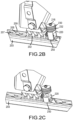
FIGS. 2B, 2C ,2D and 2E are schematic views of a series of steps used to lock the track locking assembly illustrated inFIG. 2A , in accordance with various embodiments; -
FIG. 3A is an exploded schematic view of a track locking assembly, in accordance with various embodiments; -
FIGS. 3B, 3C, and 3D are schematic views of a series of steps used to lock the track locking assembly illustrated inFIG. 3A , in accordance with various embodiments; -
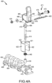
FIG. 4A is an exploded schematic view of a track locking assembly, in accordance with various embodiments; and -
FIGS. 4B, 4C and 4D are schematic views of a series of steps used to lock the track locking assembly illustrated inFIG. 4A , in accordance with various embodiments. - The following detailed description of various embodiments herein makes reference to the accompanying drawings, which show various embodiments by way of illustration. While these various embodiments are described in sufficient detail to enable those skilled in the art to practice the disclosure, it should be understood that other embodiments may be realized and that changes may be made without departing from the scope of the disclosure. Thus, the detailed description herein is presented for purposes of illustration only and not of limitation. Furthermore, any reference to singular includes plural embodiments, and any reference to more than one component or step may include a singular embodiment or step. Also, any reference to attached, fixed, connected, or the like may include permanent, removable, temporary, partial, full or any other possible attachment option. Additionally, any reference to without contact (or similar phrases) may also include reduced contact or minimal contact. It should also be understood that unless specifically stated otherwise, references to "a," "an" or "the" may include one or more than one and that reference to an item in the singular may also include the item in the plural. Further, all ranges may include upper and lower values and all ranges and ratio limits disclosed herein may be combined.
- Referring now to the drawings,
FIG. 1A schematically illustrates perspective view of aseat assembly 100 that may be used in an aircraft, a train, a bus or some other form of transportation. Theseat assembly 100 is connected to a floor via atrack assembly 190. In various embodiments, theseat assembly 100 includes thetrack assembly 190, a plurality oftrack foot assemblies 192 configured for slidable engagement with thetrack assembly 190, aseat frame 193 and a plurality oftrack lock assemblies 196. In various embodiments, theseat assembly 100 includes one of the plurality oftrack foot assemblies 192 and one of the plurality oftrack lock assemblies 196 positioned at each of four corners of theseat frame 193 that serve to releasably lock theseat frame 193 to thetrack assembly 190, which may comprise afirst track 103 positioned on afirst side 191 of theseat assembly 100 and a second track positioned on asecond side 195 of theseat assembly 100. - In various embodiments, the
first track 103 extends longitudinally along the floor of an aircraft and includes abase 184, a pair of opposingwalls 186 and a pair ofengagement members 188 extending inward from the pair of opposingwalls 186. Thebase 184 is connected to the aircraft floor using suitable fasteners, such as bolts or flush head screws. The pair of opposingwalls 186 extend upward from thebase 184. Each wall within the pair of opposingwalls 186 is spaced apart from the other and is disposed substantially parallel to the other along a length of thefirst track 103. The pair ofengagement members 188 extend inwardly and toward one another from upper portions of the pair of opposingwalls 186. The pair ofengagement members 188 each include pluralities of regularly spacedlip portions 107 andrecess portions 109. Thebase 184, the pair of opposingwalls 186 and the pluralities of regularly spacedlip portions 107 andrecess portions 109 define aslot 185. Theslot 185 extends along the length of thefirst track 103. The pluralities of regularly spacedlip portions 107 andrecess portions 109 further define a plurality ofaccess openings 105. The plurality ofaccess openings 105 are configured to receive a portion of one or more of the plurality oftrack foot assemblies 192, as described further below. - Each of a first
track foot assembly 197 and a secondtrack foot assembly 198 is at least partially received within thefirst track 103. For example, both the firsttrack foot assembly 197 and the secondtrack foot assembly 198 includes atrack foot body 102 and a plurality oftabs 106. Each of the plurality oftabs 106 extend away from thetrack foot body 102. The plurality oftabs 106 are provided with a shape complementary to the plurality ofaccess openings 105. Each of the plurality oftabs 106 extends through a corresponding one of the plurality ofaccess openings 105. The plurality oftabs 106 are received within theslot 185 of thefirst track 103. - Each of the plurality of
track foot assemblies 192 is connected to theseat frame 193 via a leg 199 (two different styles of leg are illustrated). Theseat frame 193 is secured to thetrack assembly 190 by one or more of the plurality of track foot assemblies 192 - e.g., the firsttrack foot assembly 197 and the secondtrack foot assembly 198 are secured to thefirst track 103. Each of the plurality oftrack lock assemblies 196 interfaces with thetrack assembly 190 and a respective one of the plurality oftrack foot assemblies 192 to clamp the respective one of the plurality oftrack foot assemblies 192 into thetrack assembly 190. Generally, and as explained further below, each one of the plurality oftrack lock assemblies 196 includes aplunger 120 configured to be received within one of theaccess openings 105. Theplunger 120 prevents a respective one of the plurality oftrack foot assemblies 192 from sliding fore or aft within thetrack assembly 190. Details of the track lock assemblies are now described below, in accordance with various embodiments of the disclosure. - An embodiment of the disclosure is now described with reference to
FIGS. 2A-2E . Referring first toFIG. 2A , an exploded view of atrack lock assembly 200 is illustrated in accordance with various embodiments. In various embodiments, thetrack lock assembly 200 is used as one of the plurality oftrack lock assemblies 196, described above with reference toFIGS. 1A-1C . Thetrack lock assembly 200 includes atrack foot body 202 for insertion into a track 203 (seeFIGS. 2B-2E ), such as thefirst track 103 illustrated above with reference toFIGS. 1A and1B . Thetrack foot body 202 includes alower section 204 having a plurality oftabs 206 that are configured to pass through a plurality ofaccess openings 205 formed in the track, such as theaccess openings 105 described above. Thetrack foot body 202 further includes ananchor section 208 having anaperture 210. Theaperture 210 is configured to receive apin member 212, which in various embodiments has a threadedbody 214 along its length and agrip portion 216 at its top. In various embodiments, thepin member 212 may be threaded into locking helical coil inserts positioned within theaperture 210 and be further prevented from loosening through use of a locking adhesive. Theanchor section 208 further includes a pair of opposingside walls 218 that are generally flat-sided and configured to slidably receive aplunger 220. Theplunger 220 includes a pair ofinner side walls 222 that are configured to slidably engage the pair of opposingside walls 218 of theanchor section 208. - The
track lock assembly 200 further includes afirst nut 224 and asecond nut 226, configured for threaded engagement with the threadedbody 214 of thepin member 212. Thefirst nut 224 and thesecond nut 226 may be hexagonal nuts, disk-like nuts, as illustrated, or other threaded components capable of being manipulated by an operator's fingers. In various embodiments, theaperture 210 may be threaded to receive afirst end 228 of thepin member 212. Likewise, in various embodiments, thefirst nut 224 includes aninterior portion 230 that is threaded and thesecond nut 226 includes aninterior portion 232 that is threaded. As explained further below, the threads on thefirst nut 224 and thesecond nut 226 enable the nuts to traverse the length of thepin member 212 by rotating the nuts with respect to the pin member. In various embodiments, theaperture 210 is configured to receive a first threadedinsert 234, such as a helical coil insert. Likewise, in various embodiments, theinterior portion 230 of thefirst nut 224 is configured to receive a second threadedinsert 236, as is theinterior portion 232 of thesecond nut 226. The first threadedinsert 234 and the second threadedinsert 236 provide locking threads in theaperture 210 and the interior portions of thefirst nut 224 and thesecond nut 226. In various embodiments, a bias element, such as acoil spring 240, is positioned between theanchor section 208 and theplunger 220 and serves to bias theplunger 220 away from theanchor section 208. - The
track lock assembly 200 is assembled as illustrated inFIG. 2A . Specifically, thefirst nut 224 is threaded onto thepin member 212, followed by thesecond nut 226. Thefirst nut 224 and thesecond nut 226 are threaded toward thegrip portion 216 at the top of thepin member 212. Theplunger 220 is then slidably positioned on thepin member 212 by inserting the bottom of thepin member 212 through anaperture 221 at the top of theplunger 220. Thecoil spring 240 is then slid over the bottom of thepin member 212 and the bottom of thepin member 212 is threaded into theaperture 210 in theanchor section 208. In various embodiments, following the foregoing steps, assembly of thetrack lock assembly 200 is complete and thetrack foot body 202 is ready for locking deployment into thetrack 203. In various embodiments, one or both of thefirst nut 224 and thesecond nut 226 include aknurled surface 227 to aid an operator in manipulating the nuts by hand during assembly or disassembly of thetrack lock assembly 200. - Referring now to
FIGS. 2B-2E , a series of steps used to deploy and lock thetrack lock assembly 200 within thetrack 203 is described. Starting withFIG. 2B , thetrack foot body 202, having the various components above described installed thereto, is received within thetrack 203. Thetrack foot body 202 is received within thetrack 203 by inserting the plurality oftabs 206 into the plurality ofaccess openings 205. As seen from the discussion above with reference toFIGS. 1A-1C , the plurality ofaccess openings 205 appears in regularly spaced intervals along thetrack 203 due to the configuration and spacing of a plurality of regularly spacedlip portions 207 and a plurality of regularly spacedrecess portions 209. Following receipt of thetrack foot body 202 by thetrack 203, thetrack foot body 202 is translated along the track one-half a regularly spaced interval, such that the plurality oftabs 206 is positioned directly below and adjacent a subset of the plurality of regularly spacedlip portions 207. This orientation prevents thetrack foot body 202 from being removed (or upwardly withdrawn) from thetrack 203. - Referring to
FIG. 2B , in the orientation just described, theplunger 220, which is positioned between a pair of tabs 206 (as illustrated inFIG. 2A ), sits directly above a locking access opening 250, which is one of the plurality ofaccess openings 205. Referring toFIG. 2C , theplunger 220 is urged into the locking access opening 250, against the bias provided by thecoil spring 240. Theplunger 220 may be urged into the locking access opening 250 by an operator pressing in a downward direction against theplunger 220. Referring toFIG. 2D , once theplunger 220 is fully urged into the locking access opening 250, thesecond nut 226 is threaded downward toward theplunger 220 until contacting anupper surface 223 of theplunger 220. In various embodiments, thesecond nut 226 is tightened sufficiently to bring the plurality oftabs 206 oftrack foot body 202 into contact with the plurality of regularly spacedlip portions 207 of thetrack 203, thereby minimizing or eliminating any looseness or movement between thetrack foot body 202 and thetrack 203. Contact of thesecond nut 226 against theupper surface 223 of theplunger 220 prevents thecoil spring 240 from urging theplunger 220 back out of the lockingaccess opening 250. Referring toFIG. 2E , thefirst nut 224 is now threaded downward toward theplunger 220 until contacting thesecond nut 226. Thefirst nut 224 is tightened against thesecond nut 226 to serve as a jam nut, thereby preventing thesecond nut 226 from loosening over time due to vibration. Once positioned within the locking access opening 250, theplunger 220 prevents translation of thetrack foot body 202 along thetrack 203, thereby locking a seat frame, such as theseat frame 193 described above with reference toFIG. 1A , from translational movement and minimizing or eliminating looseness between thetrack 203 and the seat frame. - An embodiment of the disclosure is now described with reference to
FIGS. 3A-3D . Referring first toFIG. 3A , an exploded view of atrack lock assembly 300 is illustrated in accordance with various embodiments. In various embodiments, thetrack lock assembly 300 is used as one of the plurality oftrack lock assemblies 196, described above with reference toFIGS. 1A-1C . Thetrack lock assembly 300 includes atrack foot body 302 for insertion into a track 303 (seeFIGS. 3B-3D ), such as thefirst track 103 illustrated above with reference toFIGS. 1A and1B . Thetrack foot body 302 includes alower section 304 having a plurality oftabs 306 that are configured to pass through a plurality ofaccess openings 305 formed in the track, such as theaccess openings 105 described above. Thetrack foot body 302 further includes ananchor section 308 having anaperture 310. Theaperture 310 is configured to receive apin member 312, which in various embodiments has a threadedbody 314 along at least a portion of its length and agrip portion 316 at its top. In various embodiments, thepin member 312 may be threaded into helical coil inserts positioned within theaperture 310 and be further prevented from loosening through use of a locking adhesive. Theanchor section 308 further includes a pair of opposingside walls 318 that are generally flat-sided and configured to slidably receive aplunger 320. Theplunger 320 includes a pair ofinner side walls 322 that are configured to slidably engage the pair of opposingside walls 318 of theanchor section 308. - The
track lock assembly 300 further includes alocking collar 351 and aretaining clip 352. Thelocking collar 351 includes a pair of opposingtabs 354, each tab having afirst hole 356 extending there through. The pair of opposingtabs 354 are configured to sandwich atab member 358 that protrudes from anupper surface 323 of theplunger 320. Thetab member 358 includes asecond hole 360 extending there through that is positioned to align with thefirst hole 356 extending through each of the pair of opposingtabs 354. Thefirst hole 356 extending through each of the pair of opposingtabs 354 and thesecond hole 360 include a diameter that is sized to receive the retainingclip 352. In various embodiments, theaperture 310 is configured to receive a first threadedinsert 334, such as a helical coil insert. In various embodiments, a bias element, such as acoil spring 340 is positioned between theanchor section 308 and theplunger 320 and serves to bias theplunger 320 away from theanchor section 308. - The
track lock assembly 300 is assembled as illustrated inFIG. 3A . Specifically, theplunger 320 is slidably positioned on thepin member 312 by inserting the bottom of thepin member 312 through anaperture 321 at the top of theplunger 320. Thecoil spring 340 is then slid over the bottom of thepin member 312 and the bottom of thepin member 312 is threaded into theaperture 310 in theanchor section 308. Thelocking collar 351 may then be positioned about thepin member 312, in between thegrip portion 316 and theupper surface 323 of theplunger 320. Thefirst hole 356 extending through each of the pair of opposingtabs 354 and thesecond hole 360 are then aligned and the retainingclip 352 is inserted through the holes. In various embodiments, awasher 362 may also be positioned adjacent thegrip portion 316 prior to assembly of the various components above described on thepin member 312. Following the foregoing steps, assembly of thetrack lock assembly 300 is complete and thetrack foot body 302 is ready for locking deployment into thetrack 303. - Referring now to
FIGS. 3B-3D , a series of steps used to deploy and lock thetrack lock assembly 300 within thetrack 303 is described. Starting withFIG. 3B , thetrack foot body 302, with thelocking collar 351 and retainingclip 352 briefly removed from thetrack lock assembly 300, is received within thetrack 303. Thetrack foot body 302 is received within thetrack 303 by inserting the plurality oftabs 306 into the plurality ofaccess openings 305. As seen from the discussion above with reference toFIGS. 1A-1C , the plurality ofaccess openings 305 appears in regularly spaced intervals along thetrack 303 due to the configuration and spacing of a plurality of regularly spacedlip portions 307 and a plurality of regularly spacedrecess portions 309. Following receipt of thetrack foot body 302 by thetrack 303, thetrack foot body 302 is translated along the track one-half a regularly spaced interval, such that the plurality oftabs 306 is positioned directly below and adjacent a subset of the plurality of regularly spacedlip portions 307. This orientation prevents thetrack foot body 302 from being removed (or upwardly withdrawn) from thetrack 303. - Referring to
FIG. 3B , in the orientation just described, theplunger 320, which is positioned between a pair of tabs 306 (as illustrated inFIG. 3A ), sits directly above a locking access opening 350, which is one of the plurality ofaccess openings 305. Referring toFIG. 3C , theplunger 320 is urged into the locking access opening 350, against the bias provided by thecoil spring 340. Theplunger 320 may be urged into the locking access opening 350 by an operator simply pressing in a downward direction against theplunger 320. Referring toFIGS. 3C and 3D , once theplunger 320 is fully urged into the locking access opening 350, thelocking collar 351 and retainingclip 352 are reassembled into thetrack lock assembly 300, locking theplunger 320 into place. The retainingclip 352 maintains thelocking collar 351 in position in the presence of vibration. In various embodiments, thegrip portion 316 may also be used to further tighten thepin member 312 against the lockingcollar 351 to prevent any rattling that might otherwise occur. Once positioned within the locking access opening 350, theplunger 320 prevents translation of thetrack foot body 302 along thetrack 303, thereby locking a seat frame, such as theseat frame 193 described above with reference toFIG. 1A , from translational movement. - An embodiment of the disclosure is now described with reference to
FIGS. 4A-4D . Referring first toFIG. 4A , an exploded view of atrack lock assembly 400 is illustrated in accordance with various embodiments. In various embodiments, thetrack lock assembly 400 is used as one of the plurality oftrack lock assemblies 196, described above with reference toFIGS. 1A-1C . Thetrack lock assembly 400 includes atrack foot body 402 for insertion into a track 403 (seeFIGS. 4B-4D ), such as thefirst track 103 illustrated above with reference toFIGS. 1A and1B . Thetrack foot body 402 includes alower section 404 having a plurality oftabs 406 that are configured to pass through a plurality ofaccess openings 405 formed in the track, such as theaccess openings 105 described above. Thetrack foot body 402 further includes ananchor section 408 having anaperture 410. Theaperture 410 is configured to receive apin member 412, which in various embodiments has a threadedbody 414 along at least a portion of its length. In various embodiments, thepin member 412 may be threaded into locking helical coil inserts positioned within theaperture 410 and be further prevented from loosening through use of a locking adhesive. Theanchor section 408 further includes a pair of opposingside walls 418 that are generally flat-sided and configured to slidably receive aplunger 420. Theplunger 420 includes a pair ofinner side walls 422 that are configured to slidably engage the pair of opposingside walls 418 of theanchor section 408. - The
track lock assembly 400 further includes acam member 460 and aretaining clip 462. Thecam member 460 is pivotally mounted to atab member 464 positioned on top of thepin member 412. Thecam member 460 includes a pair of opposingtabs 466, each tab having afirst hole 468 extending there through. The pair of opposingtabs 466 are configured to sandwich thetab member 464, which includes asecond hole 470 extending there through that is positioned to align with thefirst hole 468 extending through each of the pair of opposingtabs 466. Apivot assembly 471, which includes apin 472, a pair ofwashers 474 and anut 476 sized to thread onto thepin 472, is used to secure thecam member 460 to thetab member 464, such that thecam member 460 may pivot about thetab member 464. Thecam member 460 further includes a second pair of opposingtabs 478, each tab having athird hole 480 extending there through. The second pair of opposingtabs 478 and the retainingclip 462, when extending through eachthird hole 480, are configured to secure thecam member 460 in a locked position as described further below. Thecam member 460 further includes a lockingface 482 that is offset a distance from thefirst hole 468 in each of the pair of opposingtabs 466 in order to provide a downward push to theplunger 420 when thecam member 460 is rotated from an upright position, as illustrated inFIGS. 4B and 4C , to a downward position, as illustrated inFIG. 4D . In various embodiments, theaperture 410 is configured to receive a first threadedinsert 434, such as a helical coil insert. In various embodiments, a bias element, such as acoil spring 440 is positioned between theanchor section 408 and theplunger 420 and serves to bias theplunger 420 away from theanchor section 408 when thecam member 460 is unlocked. - The
track lock assembly 400 is assembled as illustrated inFIG. 4A . Specifically, theplunger 420 is slidably positioned on thepin member 412 by inserting the threadedbody 414 of thepin member 412 through anaperture 421 at the top of theplunger 420. Thecoil spring 440 is then slid over the threadedbody 414 of thepin member 412 and the threadedbody 414 of thepin member 412 is threaded into theaperture 410 in theanchor section 408. Thecam member 460 is then pivotally attached to thetab member 464 using thepivot assembly 471. The retainingclip 462 may also be inserted through thethird hole 480 of each of the second pair of opposingtabs 478. Following the foregoing steps, assembly of thetrack lock assembly 400 is complete and thetrack foot body 402 is ready for locking deployment into thetrack 403. - Referring now to
FIGS. 4B-4D , a series of steps used to deploy and lock thetrack lock assembly 400 within thetrack 403 is described. Starting withFIG. 4B , thetrack foot body 402, with thecam member 460 in an upright and unlocked position, is received within thetrack 403. Thetrack foot body 402 is received within thetrack 403 by inserting the plurality oftabs 406 into the plurality ofaccess openings 405. As seen from the discussion above with reference toFIGS. 1A-1C , the plurality ofaccess openings 405 appears in regularly spaced intervals along thetrack 403 due to the configuration and spacing of a plurality of regularly spacedlip portions 407 and a plurality of regularly spacedrecess portions 409. Following receipt of thetrack foot body 402 by thetrack 403, thetrack foot body 402 is translated along the track one-half a regularly spaced interval, such that the plurality oftabs 406 is positioned directly below and adjacent a subset of the plurality of regularly spacedlip portions 407. This orientation prevents thetrack foot body 402 from being removed (or upwardly withdrawn) from thetrack 403. - Referring to
FIG. 4B , in the orientation just described, theplunger 420, which is positioned between a pair of tabs 406 (as illustrated inFIG. 4A ), sits directly above a locking access opening 450, which is one of the plurality ofaccess openings 405. Referring toFIG. 4C , theplunger 420 is urged into the locking access opening 450, against the bias provided by thecoil spring 440. The retainingclip 462 is then removed from thecam member 460 and theplunger 420 is urged into the locking access opening 450 by an operator simply pressing in a downward direction against theplunger 420. Referring toFIGS. 4C and 4D , once theplunger 420 is fully urged into the locking access opening 450, thecam member 460 is rotated downward, such that the lockingface 482 rests against anupper surface 423 of theplunger 420, thereby maintaining theplunger 420 in position within the lockingaccess opening 450. The retainingclip 462 is then reinstalled, preventing thecam member 460 from rotating back to an upward position by action of the retainingclip 462 being blocked by the shaft of thepin member 412. Once positioned within the locking access opening 450, theplunger 420 prevents translation of thetrack foot body 402 along thetrack 403, thereby locking a seat frame, such as theseat frame 193 described above with reference toFIG. 1A , from translational movement. - Finally, it should be understood that any of the above described concepts can be used alone or in combination with any or all of the other above described concepts. Although various embodiments have been disclosed and described, one of ordinary skill in this art would recognize that certain modifications would come within the scope of this disclosure. Accordingly, the description is not intended to be exhaustive or to limit the principles described or illustrated herein to any precise form. Many modifications and variations are possible in light of the above teaching. Further, throughout the present disclosure, like reference numbers denote like elements. Accordingly, elements with element numbering may be shown in the figures, but may not necessarily be repeated herein for the sake of clarity.
- Benefits, other advantages, and solutions to problems have been described herein with regard to specific embodiments. Furthermore, the connecting lines shown in the various figures contained herein are intended to represent exemplary functional relationships and/or physical couplings between the various elements. It should be noted that many alternative or additional functional relationships or physical connections may be present in a practical system. However, the benefits, advantages, solutions to problems, and any elements that may cause any benefit, advantage, or solution to occur or become more pronounced are not to be construed as critical, required, or essential features or elements of the disclosure. The scope of the disclosure is accordingly to be limited by nothing other than the appended claims, in which reference to an element in the singular is not intended to mean "one and only one" unless explicitly so stated, but rather "one or more." Moreover, where a phrase similar to "at least one of A, B, or C" is used in the claims, it is intended that the phrase be interpreted to mean that A alone may be present in an embodiment, B alone may be present in an embodiment, C alone may be present in an embodiment, or that any combination of the elements A, B and C may be present in a single embodiment; for example, A and B, A and C, B and C, or A and B and C. Different cross-hatching is used throughout the figures to denote different parts but not necessarily to denote the same or different materials.
- Systems, methods and apparatus are provided herein. In the detailed description herein, references to "one embodiment", "an embodiment", "various embodiments", etc., indicate that the embodiment described may include a particular feature, structure, or characteristic, but every embodiment may not necessarily include the particular feature, structure, or characteristic. Moreover, such phrases are not necessarily referring to the same embodiment. Further, when a particular feature, structure, or characteristic is described in connection with an embodiment, it is submitted that it is within the knowledge of one skilled in the art to affect such feature, structure, or characteristic in connection with other embodiments whether or not explicitly described. After reading the description, it will be apparent to one skilled in the relevant art(s) how to implement the disclosure in alternative embodiments.
- Furthermore, no element, component, or method step in the present disclosure is intended to be dedicated to the public regardless of whether the element, component, or method step is explicitly recited in the claims. As used herein, the terms "comprises", "comprising", or any other variation thereof, are intended to cover a non-exclusive inclusion, such that a process, method, article, or apparatus that comprises a list of elements does not include only those elements but may include other elements not expressly listed or inherent to such process, method, article, or apparatus.
Claims (5)
- A track lock assembly (200, 300, 400) configured to secure a seat frame to a track, comprising:a track foot body (202, 302, 402);a pin member (212, 312, 412) having a first end secured to the track foot body and a second end extending away from the track foot body; anda plunger (220, 320, 420) slidably engaged with the pin member (212, 312, 412) between the first end and the second end, the plunger (220, 320, 420) having a cut out portion defining a first pair of opposing walls configured to slidably engage the track foot body (202, 302, 402).
- The track lock assembly of claim 1, wherein the first end of the pin member (212, 312, 412) is threadedly engaged with the track foot body (202, 302, 402), and preferably further comprising a coil spring disposed between the track foot body and the plunger.
- The track lock assembly of claim 2, further comprising a releasable lock device configured to lock the plunger into an access opening of the track.
- The track lock assembly of claim 3, wherein the releasable lock device comprises a first nut threaded onto the pin member (212, 312, 412) and configured to releasably lock the plunger into the access opening and a second nut threaded onto the pin member (212, 312, 412) and configured to jam lock the first nut.
- The track lock assembly of claim 3, wherein the releasable lock device comprises a cam member (460) pivotally attached to the second end of the pin member at a pivot point and wherein the cam member (460) includes a locking face spaced an offset distance from the pivot point and configured to provide a downward push to the plunger when rotated from an upright position to a downward position.
Applications Claiming Priority (2)
| Application Number | Priority Date | Filing Date | Title |
|---|---|---|---|
| US15/926,144 US10787263B2 (en) | 2018-03-20 | 2018-03-20 | Manual locking stud for aircraft seat |
| EP19163159.7A EP3543127B1 (en) | 2018-03-20 | 2019-03-15 | Manual locking stud for aircraft seat |
Related Parent Applications (2)
| Application Number | Title | Priority Date | Filing Date |
|---|---|---|---|
| EP19163159.7A Division EP3543127B1 (en) | 2018-03-20 | 2019-03-15 | Manual locking stud for aircraft seat |
| EP19163159.7A Division-Into EP3543127B1 (en) | 2018-03-20 | 2019-03-15 | Manual locking stud for aircraft seat |
Publications (3)
| Publication Number | Publication Date |
|---|---|
| EP4324690A2 true EP4324690A2 (en) | 2024-02-21 |
| EP4324690A3 EP4324690A3 (en) | 2024-03-27 |
| EP4324690B1 EP4324690B1 (en) | 2025-12-17 |
Family
ID=65817919
Family Applications (2)
| Application Number | Title | Priority Date | Filing Date |
|---|---|---|---|
| EP24150390.3A Active EP4324690B1 (en) | 2018-03-20 | 2019-03-15 | Track lock assembly |
| EP19163159.7A Active EP3543127B1 (en) | 2018-03-20 | 2019-03-15 | Manual locking stud for aircraft seat |
Family Applications After (1)
| Application Number | Title | Priority Date | Filing Date |
|---|---|---|---|
| EP19163159.7A Active EP3543127B1 (en) | 2018-03-20 | 2019-03-15 | Manual locking stud for aircraft seat |
Country Status (2)
| Country | Link |
|---|---|
| US (1) | US10787263B2 (en) |
| EP (2) | EP4324690B1 (en) |
Families Citing this family (7)
| Publication number | Priority date | Publication date | Assignee | Title |
|---|---|---|---|---|
| US10829225B2 (en) * | 2018-12-11 | 2020-11-10 | Ami Industries, Inc. | Track fitting with quick release lock for aircraft seating |
| US12187168B2 (en) | 2020-10-05 | 2025-01-07 | Safran Seats Usa Llc | Seat track stud with roll freedom |
| US11912415B2 (en) | 2021-01-29 | 2024-02-27 | Textron Innovations Inc. | Rotatable insert for aircraft seat base |
| US12187438B2 (en) | 2022-07-25 | 2025-01-07 | Ami Industries, Inc. | Track locking system for an aircraft seat |
| US12337972B2 (en) | 2022-07-25 | 2025-06-24 | Ami Industries, Inc. | Tracking system for an aircraft seat |
| US12428162B2 (en) | 2022-07-25 | 2025-09-30 | Ami Industries, Inc. | Motion control system for an aircraft seat |
| DE102023104252B4 (en) * | 2023-02-21 | 2024-10-31 | Franz Blum | Module assembly for a vehicle with at least one furniture module |
Citations (2)
| Publication number | Priority date | Publication date | Assignee | Title |
|---|---|---|---|---|
| US20070253762A1 (en) * | 2006-03-31 | 2007-11-01 | The Boeing Company | Apparatus and methods for removably securing payloads in an aircraft |
| JP2016216030A (en) * | 2015-05-14 | 2016-12-22 | Thk株式会社 | Seat locking device |
Family Cites Families (30)
| Publication number | Priority date | Publication date | Assignee | Title |
|---|---|---|---|---|
| US4230432A (en) * | 1979-02-27 | 1980-10-28 | Fairchild Industries, Inc. | Track fastener |
| US4449875A (en) * | 1982-07-22 | 1984-05-22 | Uop Inc. | Seat back mounting system |
| EP0200511B1 (en) | 1985-05-01 | 1992-02-19 | Ancra International Corporation | Anchor fitting for securing loads to retainer track |
| US4911381A (en) * | 1987-12-28 | 1990-03-27 | Simula, Inc. | Energy-absorbing leg assembly for aircraft passenger seats |
| US5178346A (en) * | 1991-07-12 | 1993-01-12 | Burns Aerospace Corporation | Track fastener apparatus and assembly |
| US5169091A (en) * | 1991-07-12 | 1992-12-08 | Beroth Michael T | Track fastener apparatus and assembly |
| US5871318A (en) * | 1997-11-12 | 1999-02-16 | Be Aerospace, Inc. | Quick-release track fastener |
| DE202004015211U1 (en) | 2004-09-28 | 2004-12-02 | Allsafe Jungfalk Gmbh & Co. Kg | Device for fixing of object such as aircraft seat on rail by a fitting has retainer supported in relation to sliding component by force accumulator, and connecting element has rotatable element to fix retainer in two height positions |
| US7524154B2 (en) * | 2005-11-28 | 2009-04-28 | The Boeing Company | Eccentric fastening device |
| US7713009B2 (en) | 2006-03-31 | 2010-05-11 | The Boeing Company | Apparatus and methods for removably securing payloads in an aircraft |
| US7785053B2 (en) | 2006-03-31 | 2010-08-31 | The Boeing Company | Single tough locking seat fittings and methods |
| US7665939B1 (en) * | 2006-08-10 | 2010-02-23 | Sure—Lok, Inc. | Retractor anchor with top release |
| DK1892142T3 (en) * | 2006-08-23 | 2011-02-21 | Martech Holding As | Mounting device |
| EP2019037B1 (en) * | 2007-07-27 | 2010-01-13 | Bishop GmbH Aeronautical Engineers | Airplane seat track |
| US8035956B2 (en) | 2008-09-19 | 2011-10-11 | The Boeing Company | Bulkhead mount equipment shelf rack tray |
| US8182183B2 (en) | 2008-11-18 | 2012-05-22 | L-3 Communications Integrated Systems L.P. | Systems and methods for securing components |
| DE102008062466A1 (en) * | 2008-12-17 | 2010-08-26 | Airbus Deutschland Gmbh | Device for fastening an object to a rail |
| US8292224B1 (en) | 2009-01-15 | 2012-10-23 | Timco Aviation Services, Inc. | Quick install aircraft track fitting device |
| DE102011100107A1 (en) * | 2010-10-28 | 2012-05-03 | Recaro Aircraft Seating Gmbh & Co. Kg | Seat fastening device |
| CN104093608B (en) | 2012-01-31 | 2018-06-05 | 阿尤纳·因德拉斯瓦兰·拉贾辛加姆 | Vehicle passenger support |
| FR2988686B1 (en) * | 2012-03-30 | 2015-10-02 | Sogeclair | DEVICE FOR FASTENING EQUIPMENT ON A PANEL |
| DE102013201120A1 (en) * | 2013-01-24 | 2014-07-24 | Airbus Operations Gmbh | Fastening device for releasably securing a device in the region of a floor of an aircraft or spacecraft and arrangement for a cargo loading system |
| DE102013108540A1 (en) | 2013-08-07 | 2015-02-12 | Allsafe Jungfalk Gmbh & Co. Kg | Fitting for fixing an object to a rail |
| WO2015145409A1 (en) * | 2014-03-28 | 2015-10-01 | Zodiac Seats France | Track fitting for aircraft seats |
| US9919803B2 (en) * | 2014-04-04 | 2018-03-20 | B/E Aerospace, Inc. | Aircraft seat base frame |
| FR3019601B1 (en) * | 2014-04-07 | 2017-01-06 | Attax | SYSTEM FOR FIXING AN OBJECT ON A RAIL OF A SUPPORT |
| US9546000B2 (en) * | 2015-02-26 | 2017-01-17 | Super Alloy Industrial Co., Ltd. | Fixing structure for fixing a seat of a vehicle |
| WO2017129692A1 (en) * | 2016-01-26 | 2017-08-03 | Zodiac Seats France | Stop for aircraft seat |
| US9663232B1 (en) * | 2016-04-15 | 2017-05-30 | Ami Industries, Inc. | Aircraft seat assembly having a quick change preloading track lock assembly |
| FR3073497B1 (en) * | 2017-11-10 | 2020-11-20 | Attax | SEAT ATTACHMENT SYSTEM FOR EXAMPLE OF AIRCRAFT AND SEAT INCLUDING SUCH A SYSTEM |
-
2018
- 2018-03-20 US US15/926,144 patent/US10787263B2/en active Active
-
2019
- 2019-03-15 EP EP24150390.3A patent/EP4324690B1/en active Active
- 2019-03-15 EP EP19163159.7A patent/EP3543127B1/en active Active
Patent Citations (2)
| Publication number | Priority date | Publication date | Assignee | Title |
|---|---|---|---|---|
| US20070253762A1 (en) * | 2006-03-31 | 2007-11-01 | The Boeing Company | Apparatus and methods for removably securing payloads in an aircraft |
| JP2016216030A (en) * | 2015-05-14 | 2016-12-22 | Thk株式会社 | Seat locking device |
Also Published As
| Publication number | Publication date |
|---|---|
| EP4324690A3 (en) | 2024-03-27 |
| US20190291871A1 (en) | 2019-09-26 |
| US10787263B2 (en) | 2020-09-29 |
| EP3543127B1 (en) | 2024-02-14 |
| EP4324690B1 (en) | 2025-12-17 |
| EP3543127A1 (en) | 2019-09-25 |
Similar Documents
| Publication | Publication Date | Title |
|---|---|---|
| EP4324690B1 (en) | Track lock assembly | |
| JP5252497B2 (en) | Eccentric fastening device | |
| US7997843B2 (en) | Fastener for securing together two panels | |
| US4493470A (en) | Rapid action clamping for cooperation with slot tracks | |
| US8858141B2 (en) | Barrel nut assembly | |
| US10907671B2 (en) | Fastener for securing together two panels | |
| JPH0293112A (en) | Captive screw assembly | |
| CN108281932A (en) | From indexable nutplate | |
| JP2013536384A (en) | Cage nut | |
| US11225992B2 (en) | Fastening system and methods for use | |
| US5076747A (en) | Panel fastener having internal threads and having maximum retaining ring retention capability | |
| US20140093327A1 (en) | Fastener for securing together two panels | |
| US3683988A (en) | Positive lock structural fastener | |
| CA2194521A1 (en) | Expansion connector for tubular member | |
| US8496422B2 (en) | Threaded stud with locking pawl | |
| US20210071705A1 (en) | Precision Torque Control Positive Lock Nut | |
| US3426816A (en) | Fastener receptacle | |
| EP4621250A2 (en) | Single-side fastener | |
| US20240117613A1 (en) | Faucet installtion assemblies and methods of installing the same | |
| EP4713593A1 (en) | Reusable nut configured to be fixed within hole in component and to become part of assembly with the component | |
| KR101864646B1 (en) | Anchor piece nut fastening tool for fixing insulation panel in LNG cargo | |
| US9022338B2 (en) | Template holder bracket and spring pin | |
| JPH0587114A (en) | Automatic lock clamp by which lock state can be visually checked | |
| KR20160049924A (en) | Springnut for fixing the bumper |
Legal Events
| Date | Code | Title | Description |
|---|---|---|---|
| PUAI | Public reference made under article 153(3) epc to a published international application that has entered the european phase |
Free format text: ORIGINAL CODE: 0009012 |
|
| STAA | Information on the status of an ep patent application or granted ep patent |
Free format text: STATUS: THE APPLICATION HAS BEEN PUBLISHED |
|
| REG | Reference to a national code |
Ref legal event code: R079 Ipc: B64D0011060000 Ref country code: DE Ref legal event code: R079 Ref document number: 602019079471 Country of ref document: DE Free format text: PREVIOUS MAIN CLASS: B60N0002015000 Ipc: B64D0011060000 |
|
| AC | Divisional application: reference to earlier application |
Ref document number: 3543127 Country of ref document: EP Kind code of ref document: P |
|
| AK | Designated contracting states |
Kind code of ref document: A2 Designated state(s): AL AT BE BG CH CY CZ DE DK EE ES FI FR GB GR HR HU IE IS IT LI LT LU LV MC MK MT NL NO PL PT RO RS SE SI SK SM TR |
|
| PUAL | Search report despatched |
Free format text: ORIGINAL CODE: 0009013 |
|
| AK | Designated contracting states |
Kind code of ref document: A3 Designated state(s): AL AT BE BG CH CY CZ DE DK EE ES FI FR GB GR HR HU IE IS IT LI LT LU LV MC MK MT NL NO PL PT RO RS SE SI SK SM TR |
|
| RIC1 | Information provided on ipc code assigned before grant |
Ipc: B60N 2/015 20060101ALI20240220BHEP Ipc: B64D 11/06 20060101AFI20240220BHEP |
|
| STAA | Information on the status of an ep patent application or granted ep patent |
Free format text: STATUS: REQUEST FOR EXAMINATION WAS MADE |
|
| 17P | Request for examination filed |
Effective date: 20240926 |
|
| RBV | Designated contracting states (corrected) |
Designated state(s): AL AT BE BG CH CY CZ DE DK EE ES FI FR GB GR HR HU IE IS IT LI LT LU LV MC MK MT NL NO PL PT RO RS SE SI SK SM TR |
|
| GRAP | Despatch of communication of intention to grant a patent |
Free format text: ORIGINAL CODE: EPIDOSNIGR1 |
|
| STAA | Information on the status of an ep patent application or granted ep patent |
Free format text: STATUS: GRANT OF PATENT IS INTENDED |
|
| RIC1 | Information provided on ipc code assigned before grant |
Ipc: B64D 11/06 20060101AFI20250620BHEP Ipc: B60N 2/015 20060101ALI20250620BHEP |
|
| INTG | Intention to grant announced |
Effective date: 20250714 |
|
| GRAS | Grant fee paid |
Free format text: ORIGINAL CODE: EPIDOSNIGR3 |
|
| GRAA | (expected) grant |
Free format text: ORIGINAL CODE: 0009210 |
|
| STAA | Information on the status of an ep patent application or granted ep patent |
Free format text: STATUS: THE PATENT HAS BEEN GRANTED |
|
| AC | Divisional application: reference to earlier application |
Ref document number: 3543127 Country of ref document: EP Kind code of ref document: P |
|
| AK | Designated contracting states |
Kind code of ref document: B1 Designated state(s): AL AT BE BG CH CY CZ DE DK EE ES FI FR GB GR HR HU IE IS IT LI LT LU LV MC MK MT NL NO PL PT RO RS SE SI SK SM TR |
|
| REG | Reference to a national code |
Ref country code: CH Ref legal event code: F10 Free format text: ST27 STATUS EVENT CODE: U-0-0-F10-F00 (AS PROVIDED BY THE NATIONAL OFFICE) Effective date: 20251217 Ref country code: GB Ref legal event code: FG4D |
|
| REG | Reference to a national code |
Ref country code: DE Ref legal event code: R096 Ref document number: 602019079471 Country of ref document: DE |
|
| REG | Reference to a national code |
Ref country code: LT Ref legal event code: MG9D |
|
| PG25 | Lapsed in a contracting state [announced via postgrant information from national office to epo] |
Ref country code: NO Free format text: LAPSE BECAUSE OF FAILURE TO SUBMIT A TRANSLATION OF THE DESCRIPTION OR TO PAY THE FEE WITHIN THE PRESCRIBED TIME-LIMIT Effective date: 20260317 |
|
| PG25 | Lapsed in a contracting state [announced via postgrant information from national office to epo] |
Ref country code: FI Free format text: LAPSE BECAUSE OF FAILURE TO SUBMIT A TRANSLATION OF THE DESCRIPTION OR TO PAY THE FEE WITHIN THE PRESCRIBED TIME-LIMIT Effective date: 20251217 Ref country code: HR Free format text: LAPSE BECAUSE OF FAILURE TO SUBMIT A TRANSLATION OF THE DESCRIPTION OR TO PAY THE FEE WITHIN THE PRESCRIBED TIME-LIMIT Effective date: 20251217 |
|
| PG25 | Lapsed in a contracting state [announced via postgrant information from national office to epo] |
Ref country code: RS Free format text: LAPSE BECAUSE OF FAILURE TO SUBMIT A TRANSLATION OF THE DESCRIPTION OR TO PAY THE FEE WITHIN THE PRESCRIBED TIME-LIMIT Effective date: 20260317 |
|
| PGFP | Annual fee paid to national office [announced via postgrant information from national office to epo] |
Ref country code: FR Payment date: 20260220 Year of fee payment: 8 |
|
| REG | Reference to a national code |
Ref country code: NL Ref legal event code: MP Effective date: 20251217 |
|
| PG25 | Lapsed in a contracting state [announced via postgrant information from national office to epo] |
Ref country code: LV Free format text: LAPSE BECAUSE OF FAILURE TO SUBMIT A TRANSLATION OF THE DESCRIPTION OR TO PAY THE FEE WITHIN THE PRESCRIBED TIME-LIMIT Effective date: 20251217 |
|
| PG25 | Lapsed in a contracting state [announced via postgrant information from national office to epo] |
Ref country code: BG Free format text: LAPSE BECAUSE OF FAILURE TO SUBMIT A TRANSLATION OF THE DESCRIPTION OR TO PAY THE FEE WITHIN THE PRESCRIBED TIME-LIMIT Effective date: 20251217 |