EP4324363A1 - Cooking appliance - Google Patents
Cooking appliance Download PDFInfo
- Publication number
- EP4324363A1 EP4324363A1 EP21936673.9A EP21936673A EP4324363A1 EP 4324363 A1 EP4324363 A1 EP 4324363A1 EP 21936673 A EP21936673 A EP 21936673A EP 4324363 A1 EP4324363 A1 EP 4324363A1
- Authority
- EP
- European Patent Office
- Prior art keywords
- pot
- control switch
- touch
- cooking appliance
- electrically connected
- Prior art date
- Legal status (The legal status is an assumption and is not a legal conclusion. Google has not performed a legal analysis and makes no representation as to the accuracy of the status listed.)
- Pending
Links
- 238000010411 cooking Methods 0.000 title claims abstract description 43
- 238000010438 heat treatment Methods 0.000 claims abstract description 147
- 239000004020 conductor Substances 0.000 claims description 41
- 230000005540 biological transmission Effects 0.000 claims description 32
- 239000012528 membrane Substances 0.000 claims description 3
- 238000000034 method Methods 0.000 description 7
- 239000003086 colorant Substances 0.000 description 4
- 235000013305 food Nutrition 0.000 description 3
- NJPPVKZQTLUDBO-UHFFFAOYSA-N novaluron Chemical compound C1=C(Cl)C(OC(F)(F)C(OC(F)(F)F)F)=CC=C1NC(=O)NC(=O)C1=C(F)C=CC=C1F NJPPVKZQTLUDBO-UHFFFAOYSA-N 0.000 description 3
- 239000000243 solution Substances 0.000 description 3
- XAGFODPZIPBFFR-UHFFFAOYSA-N aluminium Chemical compound [Al] XAGFODPZIPBFFR-UHFFFAOYSA-N 0.000 description 2
- 229910052782 aluminium Inorganic materials 0.000 description 2
- 230000000694 effects Effects 0.000 description 2
- 239000000463 material Substances 0.000 description 2
- 238000004078 waterproofing Methods 0.000 description 2
- RYGMFSIKBFXOCR-UHFFFAOYSA-N Copper Chemical compound [Cu] RYGMFSIKBFXOCR-UHFFFAOYSA-N 0.000 description 1
- 240000007594 Oryza sativa Species 0.000 description 1
- 235000007164 Oryza sativa Nutrition 0.000 description 1
- 230000033228 biological regulation Effects 0.000 description 1
- 229910052802 copper Inorganic materials 0.000 description 1
- 239000010949 copper Substances 0.000 description 1
- 230000005611 electricity Effects 0.000 description 1
- 230000005672 electromagnetic field Effects 0.000 description 1
- 238000005516 engineering process Methods 0.000 description 1
- 238000001746 injection moulding Methods 0.000 description 1
- 239000012774 insulation material Substances 0.000 description 1
- 235000009566 rice Nutrition 0.000 description 1
- 230000009466 transformation Effects 0.000 description 1
- 230000000007 visual effect Effects 0.000 description 1
- XLYOFNOQVPJJNP-UHFFFAOYSA-N water Substances O XLYOFNOQVPJJNP-UHFFFAOYSA-N 0.000 description 1
Images


Classifications
-
- A—HUMAN NECESSITIES
- A47—FURNITURE; DOMESTIC ARTICLES OR APPLIANCES; COFFEE MILLS; SPICE MILLS; SUCTION CLEANERS IN GENERAL
- A47J—KITCHEN EQUIPMENT; COFFEE MILLS; SPICE MILLS; APPARATUS FOR MAKING BEVERAGES
- A47J27/00—Cooking-vessels
- A47J27/004—Cooking-vessels with integral electrical heating means
-
- A—HUMAN NECESSITIES
- A47—FURNITURE; DOMESTIC ARTICLES OR APPLIANCES; COFFEE MILLS; SPICE MILLS; SUCTION CLEANERS IN GENERAL
- A47J—KITCHEN EQUIPMENT; COFFEE MILLS; SPICE MILLS; APPARATUS FOR MAKING BEVERAGES
- A47J27/00—Cooking-vessels
- A47J27/08—Pressure-cookers; Lids or locking devices specially adapted therefor
- A47J27/086—Pressure-cookers; Lids or locking devices specially adapted therefor with built-in heating means
-
- A—HUMAN NECESSITIES
- A47—FURNITURE; DOMESTIC ARTICLES OR APPLIANCES; COFFEE MILLS; SPICE MILLS; SUCTION CLEANERS IN GENERAL
- A47J—KITCHEN EQUIPMENT; COFFEE MILLS; SPICE MILLS; APPARATUS FOR MAKING BEVERAGES
- A47J27/00—Cooking-vessels
- A47J27/08—Pressure-cookers; Lids or locking devices specially adapted therefor
- A47J27/0802—Control mechanisms for pressure-cookers
-
- A—HUMAN NECESSITIES
- A47—FURNITURE; DOMESTIC ARTICLES OR APPLIANCES; COFFEE MILLS; SPICE MILLS; SUCTION CLEANERS IN GENERAL
- A47J—KITCHEN EQUIPMENT; COFFEE MILLS; SPICE MILLS; APPARATUS FOR MAKING BEVERAGES
- A47J36/00—Parts, details or accessories of cooking-vessels
- A47J36/24—Warming devices
-
- A—HUMAN NECESSITIES
- A47—FURNITURE; DOMESTIC ARTICLES OR APPLIANCES; COFFEE MILLS; SPICE MILLS; SUCTION CLEANERS IN GENERAL
- A47J—KITCHEN EQUIPMENT; COFFEE MILLS; SPICE MILLS; APPARATUS FOR MAKING BEVERAGES
- A47J36/00—Parts, details or accessories of cooking-vessels
- A47J36/32—Time-controlled igniting mechanisms or alarm devices
Definitions
- the present disclosure relates to the field of household appliance technology, and in particular to a cooking appliance.
- the heating assembly may be generally controlled only by means of operating a control switch (including a knob or a key), which is not very convenient for a user.
- the present disclosure provides a cooking appliance that is capable of controlling a heating assembly by means of operating a first control switch of a pot.
- a first technical solution adopted by the present disclosure is to provide a cooking appliance.
- the cooking appliance includes a pot, including a first control switch; and a heating assembly, configured to heat the pot and including a control circuit board, where the heating assembly and the pot are arranged separately; where the first control switch is associated with the control circuit board, and the heating assembly is controlled.
- the heating assembly further includes a second control switch electrically connected to the control circuit board, and the first control switch is connected to the second control switch.
- the pot further includes a transmission conductor, and the first control switch is electrically connected to the second control switch via the transmission conductor.
- the first control switch includes: a first touch key, arranged on a surface of the pot; a first touch spring, where an end of the first touch spring is electrically connected to the first touch key, and the other end of the first touch spring is electrically connected to the transmission conductor.
- the first control switch includes a touch conductor, one end of the touch conductor is arranged on a surface of the pot, and the other end of the touch conductor is electrically connected to the transmission conductor.
- the second control switch includes: a second touch key, arranged on a side surface of the heating assembly close to the pot and electrically connected to the transmission conductor; and a second touch spring, where one end of the second touch spring is electrically connected to the second touch key, and the other end of the second touch spring is electrically connected to the control circuit board.
- the pot further includes a transmission member; in response to a control operation of a user, the first control switch is configured to drive the transmission member to trigger the second control switch, and the heating assembly is controlled.
- the second control switch is a touch switch or a membrane switch, and the second control switch is welded on the control circuit board.
- the pot further includes a receiving coil board electrically connected to the first control switch; the heating assembly further includes a transmitting coil board electrically connected to the control circuit board; and the transmitting coil board cooperates with the receiving coil board, such that the first control switch is connected to the control circuit board.
- the first control switch includes: a first touch key, arranged on a surface of the pot, and configured to receive a control operation of a user and generate a corresponding electrical signal; and a first touch spring, one end of the first touch spring being electrically connected to the first touch key; and a touch circuit board, electrically connected to the other end of the first touch spring, where the touch circuit board is electrically connected to the receiving coil board, and the touch circuit board is configured to amplify the electrical signal and transmit an amplified electrical signal to the receiving coil board.
- the transmitting coil board cooperates with the receiving coil board and is further configured to supply power to an electrical component of the pot.
- the heating assembly includes: a heating main body, where a side of the heating main body close to the pot defines a sinking groove, and the transmitting coil board is arranged in the sinking groove; and a decorative member, sleeved on the heating main body and configured to fix the transmitting coil board in the sinking groove.
- the heating assembly includes a heating body, a side post body, and a decorative member, the side post body is arranged on a sidewall of the heating body, and the decorative member is sleeved on the side post body; and the pot includes a pot body and a pot side post, the pot body is arranged correspondingly to the heating body, the pot side post is arranged correspondingly to the side post body, and the first control switch is arranged on the pot side post.
- the first control switch of the pot is associated with the control circuit board of the heating assembly, that is, by means of establishing a connection between the first control switch of the pot and the control circuit board of the heating assembly, it is possible to control the heating assembly by operating the first control switch of the pot, which is more convenient for the user.
- FIG. 1 is a structural schematic view of a cooking appliance according to some embodiments of the present disclosure.
- the cooking appliance 600 described in some embodiments of the present disclosure includes a pot 200 and a heating assembly 100.
- the pot 200 is configured to accommodate food to be cooked.
- the heating assembly 100 is configured to heat the pot 200, and the pot 200 is detachably arranged on the heating assembly 100.
- the heating assembly 100 may include a complete heating and control system, and may be used as a separate heating magnetic furnace to achieve multi-functional product requirement.
- the heating assembly 100 may be arranged with a positioning protrusion or convex block 601, and the pot 200 may be arranged with a positioning groove.
- the positioning groove is matched with the positioning protrusion 601, so as to limit a relative position of the pot 200 and the heating assembly 100.
- the pot 200 may further be arranged with a first control switch 240.
- the first control switch 240 may be configured to receive a control operation of a user.
- the first control switch 240 is connected to a control circuit board 30 (as shown in FIG. 6 ) of the heating assembly 100, so as to control the heating assembly 100.
- the first control switch 240 of the pot 200 is associated with the control circuit board 30 of the heating assembly 100, that is, by means of establishing a connection between the first control switch 240 of the pot 200 and the control circuit board 30 of the heating assembly 100, it is possible to control the heating assembly 100 by operating the first control switch 240 of the pot 200, which is more convenient for the user.
- the heating assembly 100 includes a heating main body and a decorative member sleeved on the heating main body.
- the heating main body may include a heating body 10 and a side post body 201 (as shown in FIG. 1 , the side post body 201 is covered by a decorative member 202, and the side post body 201 is shown in FIG. 2 ).
- the side post body 201 is arranged on an outer wall of the heating body 10.
- the heating body 10 is configured to heat the pot 200, and the decorative member 202 is sleeved on the side post body 201.
- the pot 200 may include a pot body 210 and a pot side post 220.
- the pot body 210 is configured to accommodate the food to be cooked, and is arranged correspondingly to the heating body 10.
- the pot side post 220 is connected to an outer wall of the pot body 210, and is arranged correspondingly to or facing the side post body 201.
- the first control switch 240 is arranged on the pot side post 220. In some embodiments, the first control switch 240 may also be arranged on the pot body 210. In some embodiments, the pot 200 may also not include the pot side post 220, and the first control switch 240 is arranged on the pot body 210, which is not limited herein, and which may be selected by those skilled in the art according to actual needs.
- a color of the pot body 210 may be the same as that of the heating body 10.
- a color of the pot side post 220 may be the same as that of the decorative member 202.
- the colors of the pot side post 220 and the decorative member 202 may be different from the colors of the pot body 210 and the heating body 10, such that an appearance color of the cooking appliance 600 may be more eye-catching.
- the colors of these components are not limited herein, and may be selected by those skilled in the art according to actual needs.
- the cooking appliance 600 may further include a pot cover assembly 300.
- the decorative member 202, the pot side post 220, and an outer shell of the pot cover assembly 300 may have the same color scheme, so as to visually connect the entire cooking appliance 600 as a whole and form the visual tone of the entire product.
- the pot 200 is arranged with an electrical component 230, such as an indicator light, a temperature sensor, etc.
- the electrical component 230 may be arranged on the pot side post 220.
- the electrical component 230 may also be arranged on the pot body 210.
- some of the electrical component 230 may be arranged on the pot side post 220, and others of the electrical component 230 may be arranged on the pot body 210, which is not limited herein, and which may be selected by those skilled in the art according to actual needs.
- FIG. 2 is a schematic sectional view of the cooking appliance shown in FIG. 1 .
- a transmitting coil board 203 is arranged on a side of the side post body 201 close to or adjacent to the pot side post 220.
- a receiving coil board 221 is arranged on a side of the pot side post 220 close to or adjacent to the side post body 201. The receiving coil board 221 cooperates with the transmitting coil board 203, so as to supply power to the electrical component 230 of the pot 200.
- the transmitting coil board 203 may be electrically connected to the power supply (not shown) of the heating assembly 100.
- the power supply provides high-frequency AC (alternating current) power to the transmitting coil board 203.
- the transmitting coil board 203 may be capable of generating an alternating electromagnetic field that acts on the receiving coil board 221, such that an alternating current may be generated by the receiving coil board 221.
- the receiving coil board 221 is connected to the electrical component 230 of the pot 200 (such as the indicator light, the temperature sensor, etc.), so as to input current to the electrical component 230 of the pot 200, thereby enabling the electrical component 230 to work normally. That is, wireless power supply of the electrical component 230 of the pot 200 is achieved by means of arranging the transmitting coil board 203 on the side post body 201 and arranging the receiving coil board 221 on the pot side post 220.
- FIG. 6 is a partial structural schematic view of the heating assembly of the cooking appliance shown in FIG. 1 .
- a sinking groove 20111 is defined on a side surface of the side post body 201 close to the pot side post 220, and is configured to accommodate the transmitting coil board 203.
- the decorative member 202 is sleeved on the side post body 201, and is configured to fix the transmitting coil board 203 in the sinking groove 20111.
- a size of the sinking groove 20111 may be matched with a size of the transmitting coil board 203, such that the transmitting coil board 203 may be completely limited and unable to move.
- the assembly solution may omit a screw, a fastener, and other connection structures, such that a structure of the side post body 201 is simplified, and it facilities improving the assembly efficiency of the product.
- the heating main body may not include the side post body 201.
- the sinking groove 20111 may be arranged on a side surface of the heating body 10 close to the pot 200, the transmitting coil board 203 may be arranged in the sinking groove, and the decorative member may be sleeved on the entire heating body 10 to fix the transmitting coil board in the sinking groove.
- the heating assembly 100 may also not include the decorative member 202, and the transmitting coil board 203 may be fixed to the side post body 201 via a connecting structure such as a screw, a fastener, etc., which is not limited herein, and which may be selected by those skilled in the art according to actual needs.
- the first control switch 240 is configured to receive the control operation of the user and generate a corresponding electrical signal. In some embodiments, the first control switch 240 may be configured to generate the corresponding electrical signal when touched by the user, or the first control switch 240 may generate the corresponding electrical signal when pressed by the user, or the first control switch 240 may generate the corresponding electrical signal when rotated by the user, which is not limited herein, and which may be selected by those skilled in the art according to actual needs.
- FIG. 3 is another schematic sectional view of the cooking appliance shown in FIG. 1 .
- the receiving coil board 221 is electrically connected to the first control switch 240, such as by means of a wire.
- the transmitting coil board 203 is electrically connected to the control circuit board 30 of the heating assembly 100, such as by means of a wire.
- the receiving coil board 221 cooperates or operates with the transmitting coil board 203, so as to transmit the electrical signal generated by the first control switch 240 and corresponding to the control operation of the user to the control circuit board 30 of the heating assembly 100.
- the first control switch 240 may include a first touch key 241, a first touch spring 242, and a touch circuit board 243.
- the first touch key 241 is arranged on a surface of the pot 200, such as a surface of the pot side post 220.
- the first touch key 241 is configured to receive the control operation of the user and generate the electrical signal corresponding to the control operation of the user.
- the first touch key 241 may be a capacitive touch switch or a resistive touch switch.
- the first touch spring 242 and the touch circuit board 243 may be arranged inside the pot side post 220.
- One end of the first touch spring 242 is electrically connected to the first touch key 241, and the other end of the first touch spring 242 is electrically connected to the touch circuit board 243, so as to transmit the electrical signal generated by the first touch key 241 and corresponding to the control operation of the user to the touch circuit board 243.
- the touch circuit board 243 is electrically connected to the receiving coil board 221.
- the touch circuit board 243 is connected to the receiving coil board 221, such as by means of a wire.
- the touch circuit board 243 is configured to amplify the electrical signal generated by the first touch key 241 and corresponding to the control operation of the user, and transmit an amplified electrical signal to the receiving coil board 221.
- the receiving coil board 221 Under the action of the amplified electrical signal, the receiving coil board 221 generates an induced magnetic field that acts on the transmitting coil board 203, such that an induced current corresponding to the electrical signal may be generated by the transmitting coil board 203.
- the transmitting coil board 203 transmits a corresponding induced current to the control circuit board 30 of the heating assembly 100, so as to control the heating assembly 100.
- the first control switch 240 may not include the first touch spring 242.
- the touch key 241 may be electrically connected to the touch circuit board 243 by means of a conductor in any form.
- the first touch key 241 is directly welded on the touch circuit board 243, which is not limited herein, and which may be selected by those skilled in the art according to actual needs.
- the transmitting coil board 203 may be connected to the control circuit board 30 of the heating assembly 100 via a circuit.
- a terminal 2031 is arranged on a side of the transmitting coil board 203 close to the receiving coil board 221.
- the terminal 2031 is arranged on an end of the transmitting coil board 203 close to the heating body 10.
- the transmitting coil board 203 is connected to the control circuit board 30 of the heating assembly 10 via the terminal 2031.
- the sinking groove 20111 may be further arranged with a support member.
- the support member is configured to support the transmitting coil board 203, such that a side of the transmitting coil board 203 away from the heating body 10 may be inclined to a direction close to or facing the receiving coil board 221.
- the terminal 2031 is arranged on a side surface of the transmitting coil board 203 close to the receiving coil board 221, and is arranged on a side of the transmitting coil board 203 close to the heating body 10. Due to a certain height of the terminal 2031 (i.e., the height thereof is generally in a range from 10mm to 20mm), if the transmitting coil board 203 is substantially arranged parallel to the receiving coil board 221, a distance between the transmitting coil board 203 and the receiving coil board 221 cannot be further reduced due to presence/existence of the terminal 2031, resulting in affecting cooperation between the transmitting coil board 203 and the receiving coil board 221.
- the side of the transmitting coil board 203 away from the heating body 10 may be inclined to the direction close to the receiving coil board 221, which facilitates reducing the distance between the transmitting coil board 203 and the receiving coil board 221, thereby ensuring working performance of the transmitting coil board 203 and the receiving coil board 221.
- two support ribs 20112 are arranged at intervals on a bottom of the sinking groove 20111.
- the two support ribs 20112 may be served as the above-mentioned support member and configured to support the transmitting coil board 203.
- the two support ribs 20112 extend in a direction away from the heating body 10, and a height of each of the two support ribs 20112 gradually increases, such that the side of the transmitting coil board 203 away from the heating body 10 may be inclined to the direction close to the receiving coil board 221.
- one support rib 20112 may further be arranged on a side of the bottom of the sinking groove 20111 away from the heating body 10, such that the side of the transmitting coil board 203 close to the heating body 10 may abut against the bottom of the sinking groove 20111, and the side of the transmitting coil board 203 away from the heating body 10 is arranged on the support rib 20112. In this way, the side of the transmitting coil board 203 away from the heating body 10 may be inclined to the direction close to the receiving coil board 221.
- a gap is defined between the bottom of the sinking groove 20111 and the transmitting coil board 203, which facilitates dissipating heat for the transmitting coil board 203.
- the bottom of the sinking groove 20111 may also be arranged as an inclined surface, such that the side of the transmitting coil board 203 away from the heating body 10 may be inclined to the direction close to the receiving coil board 221.
- the transmitting coil board 203 cooperates with the receiving coil board 221, and is further configured to transmit a temperature signal detected by the temperature sensor of the pot 200.
- the temperature sensor is configured to monitor temperature inside the pot 200 in real-time, convert the temperature signal into an electrical signal, generate the alternating current via the receiving coil board, and generate the alternating magnetic field.
- a corresponding induced current may be generated by the transmitting coil board 203 of the side post body 201 under the action of the alternating magnetic field.
- a chip of the circuit board 30 is controlled to decode the induced current, and convert the induced current into the temperature signal inside the pot 200, thereby controlling the heating body 10 based on the temperature signal.
- the control circuit board 30 may control the heating body 10 based on the temperature inside the pot 200. In some embodiments, when the temperature inside the pot 200 is lower than a first threshold, the control circuit board 30 may turn on the heating body 10 or increase a heating power of the heating body 10, so as to increase the temperature inside the pot 200. When the temperature inside the pot 200 is greater than a second threshold, the control circuit board 30 may turn off the heating body 10 or reduce the heating power of the heating body 10, so as to decrease the temperature inside the pot 200.
- the value range of the first threshold may be from 80°C to 120°C, such as 80°C, 90°C, 100°C, 110°C, and 120°C, etc.
- the value range of the second threshold may be from 120 to 160°C, such as 120°C, 130°C, 140°C, 150°C, and 160°C, etc.
- a value of the first threshold and a value of the second threshold are not limited herein, which may be selected by those skilled in the art according to actual needs.
- control circuit board 30 controlling the heating body 10 by the control circuit board 30 is only an example, and is not a limitation of the present disclosure. Within the scope easy to understand by those skilled in the art, those skilled in the art can make choices according to actual needs.
- the heating assembly 100 will be described below, which may refer to the description of the heating assembly in the embodiments below for details.
- FIG. 4 is a structural schematic view of a heating assembly of the cooking appliance shown in FIG. 1 .
- the heating assembly 100 includes a heating main body and a decorative member sleeved on the heating main body.
- the heating main body may include the heating body 10 and the side post body 201.
- the decorative member 202 is sleeved on the side post body 201.
- the heating body 10 and the side post body 201 may be integrally formed.
- the heating body 10 and the side post body 201 may also be arranged separately or independently or individually, or the heating body 10 and the side post body 201 is two individual parts.
- the product has a poor product reliability and the following problems such as waterproofing, safety regulations, creepage distance, and structural strength may occur.
- waterproofing regardless of an assembly method for arranging the heating body 10 and the side post body 201, there will be a problem that water enters inside of the product along an assembly gap between the heating body 10 and the side post body 201, leading to damage or failure of the product function.
- the heating body 10 and the side post body 201 are integrally formed, it facilitates improving an appearance effect of the heating assembly 100 by arranging the decorative member 202.
- the decorative member 202 is arranged to enable the heating body 10 and the side post (including the side post body 201 and decorative member 202) to have different colors. Without the decorative member 202, it is difficult to realize dual-color injection molding of the heating body 10 and the side post body 201 due to the limitation of an existing technological process.
- the heating assembly 100 may be a heating magnetic furnace.
- the heating body 10 may be arranged in a circular shape.
- the side post body 201 extends outward from the outer wall of the heating body 10.
- the heating body 10 may also be arranged in a square shape, which is not limited herein, and which may be selected by those skilled in the art according to actual needs.
- FIG. 5 is an exploded structural schematic view of the heating assembly shown in FIG. 4 .
- the heating body 10 includes a housing 101, a panel 102, and a heating source 103.
- the side post body 201 and the housing 101 are integrally formed.
- the panel 102 is covered on the housing 101.
- the panel 102 and the housing 101 cooperatively define an accommodating space to accommodate the heating source 103.
- the heating source 103 may be a coil, which is not limited herein, and which may be selected by those skilled in the art according to actual needs.
- the housing 101 may include a middle frame 1011 and a base 1012. As shown in FIG. 5 , the middle frame 1011 and the base 1012 may be arranged separately. The base 1012 and the panel 102 are respectively arranged on two sides of the middle frame 1011.
- the side post body 201 may include a first side post body 2011 and a second side post body 2012. As shown in FIG. 5 , the first side post body 2011 and the second side post body 2012 may be arranged separately. In some embodiments, the first side post body 2011 and the middle frame 1011 may be integrally formed. The second side post body 2012 and the base 1012 may be integrally formed.
- the middle frame 1011 and the base 1012 may be integrally formed. Accordingly, the first side post body 2011 and the second side post body 2012 may also be integrally formed, which is not limited herein, and which may be selected by those skilled in the art according to actual needs.
- FIG. 7 is a structural schematic view of a control circuit board of the heating assembly shown in FIG. 5 .
- the control circuit board 30 of the heating assembly 100 is disposed in the side post body 201 and extends out of the side post body 201, so as to control the heating body 10.
- the first side post body 2011 and the second side post body 2012 may cooperatively define an accommodating cavity (not shown).
- the control circuit board 30 may be arranged in the accommodating cavity defined by the first side post body 2011 and the second side post body 2012. At least a part of a structure of the control circuit board 30 extends into the heating body 10, so as to control the heating body 10.
- the heating assembly 100 may further include a second control switch 420 electrically connected to the control circuit board 30.
- the first control switch 240 is connected to the second control switch 420.
- the first control switch 240 may be electrically connected to the second control switch 420.
- the first control switch 240 is configured to receive the control operation of the user and generate the corresponding electrical signal.
- the second control switch 420 is configured to receive the electrical signal generated by the first control switch 240 and transmit the electrical signal to the control circuit board 30 of the heating assembly 100, so as to control the heating assembly 100.
- FIG. 8 is another schematic sectional view of the cooking appliance shown in FIG. 1 .
- the pot 200 may further include a transmission conductor 410.
- the transmission conductor 410 may be arranged inside the pot side post 220.
- the second control switch 420 is arranged on the heating assembly 100 and electrically connected to the control circuit board 30 of the heating assembly 100.
- the first control switch 240 is electrically connected to the second control switch 420 via the transmission conductor 410.
- the first control switch 240 may include the first touch key 241 and the first touch spring 242.
- the first touch key 241 is arranged on the surface of the pot 200, such as the surface of the pot side post 220.
- the first touch key 241 is configured to receive the control operation of the user and generate the electrical signal corresponding to the control operation of the user.
- the first touch key 241 may be the capacitive touch switch or the resistive touch switch.
- the first touch spring 242 may be arranged inside the pot side post 220.
- One end of the first touch spring 242 is electrically connected to the first touch key 241, and the other end of the first touch spring 242 is electrically connected to the transmission conductor 410, so as to transmit the electrical signal generated by the first touch key 241 and corresponding to the control operation of the user to the transmission conductor 410.
- the transmission conductor 410 may be a conductor in any form, such as an aluminum sheet or a wire.
- a structure and a material of the transmission conductor 410 are not limited herein, which may be selected by those skilled in the art according to actual needs.
- the second control switch 420 may include a second touch key 421 and a second touch spring 422.
- the second touch key 421 is arranged on a side surface of the heating assembly 100 close to the pot 200, and is electrically connected to the transmission conductor 410 to receive the electrical signal from the transmission conductor 410.
- the second touch key 421 may be a capacitive touch switch or a resistive touch switch. As shown in FIG. 8 , the second touch key 421 may be arranged on a side surface of the decorative member 202 close to the pot side post 220.
- the second touch spring 422 may be arranged in the side post body 201. One end of second touch spring 422 is electrically connected to the second touch key 421, and the other end of the second touch spring 422 is electrically connected to the control circuit board 30 of the heating assembly 100.
- the second touch spring 422 is configured to transmit the electrical signal received by the second touch key 421 to the control circuit board 30 of the heating assembly 100.
- the control circuit board 30 controls the heating body 10 to heat the pot 200 based on the electrical signal.
- the second touch key 421 may be further configured to receive another control operation of the user and generate an electrical signal corresponding to the another control operation of the user.
- the transmission conductor 410 may be an elastic member. In a compressed state, the transmission conductor 410 is capable of generating a certain amount of elastic force. The transmission conductor 410 may be pushed towards the second touch key 421 of the heating assembly 100 via the elastic force, which facilitates ensuring a reliable connection between the transmission conductor 410 and the second touch key 421.
- FIG. 9 is another schematic sectional view of the cooking appliance shown in FIG. 1 .
- the first control switch 240 is a touch conductor.
- the touch conductor is capable of generating the electrical signal when touched by a human body.
- the touch conductor may be a conductor in any form, such as an aluminum sheet or a copper sheet, as long as the conductor is capable of conducting electricity.
- a structure and a material of the touch conductor are not limited herein, which may be selected by those skilled in the art according to actual needs.
- One end of the touch conductor is arranged on the surface of the pot 200, and is configured to receive the control operation of the user and generate the electrical signal corresponding to the control operation of the user.
- the other end of the touch conductor is electrically connected to the transmission conductor 410, so as to transmit the generated electrical signal to the transmission conductor 410.
- the first control switch 240 may also be a mechanical structure switch.
- the pot may further include a transmission member (not shown).
- the first control switch 240 is configured to drive the transmission member to trigger the second control switch 420, so as to control the heating assembly 100.
- the second control switch 420 is a touch switch or a membrane switch. the second control switch 420 is welded on the control circuit board 30. Under the force applied by the user, the first control switch 240 is configured to drive the transmission member to trigger the second control switch 420.
- FIG. 10 is a structural schematic view of a pot of the cooking appliance shown in FIG. 1 .
- the pot body 210 may include an inner liner 211, an outer shell 212, a support base 213, and an outer shell cover 214.
- the inner liner 211 is configured to accommodate the food to be cooked.
- the pedestal 213 and the outer shell 212 cooperatively define an accommodating space.
- the inner liner 211 is fixed in the accommodating space defined by the pedestal 213 and the outer shell 212 via the outer shell cover 214.
- the outer shell 212 and the pedestal 213 may be made of an insulation material, such that it may be possible to allow the user to place the pot 200 on a dining table after cooking, and prevent the table and the user from being scalding.
- first”, “second”, and “third” in the present disclosure are used for descriptive purposes only, and shall not be interpreted as indicating or implying relative importance or implicitly specifying the number of an indicated technical feature. Therefore, a feature defined by the terms “first”, “second”, and “third” may explicitly or implicitly include at least one such feature.
- "a plurality of' means at least two, such as two, three, and so on, unless otherwise expressly and specifically limited. All directional indications (such as up, down, left, right, forward, backward%) in the present disclosure are used only to explain relative positions and movements of components in a particular attitude (the attitude shown in the corresponding drawing). When the particular attitude is changed, the directional indications may be changed accordingly.
Landscapes
- Engineering & Computer Science (AREA)
- Food Science & Technology (AREA)
- Cookers (AREA)
- Electric Stoves And Ranges (AREA)
- Induction Heating Cooking Devices (AREA)
Abstract
Description
- The present application claims priority to
Chinese Patent Application No. 202120794597.7, filed on April 16, 2021 - The present disclosure relates to the field of household appliance technology, and in particular to a cooking appliance.
- In a cooking appliance such as a rice cooker and an electric pressure cooker, when a pot and a heating assembly are detachable, the heating assembly may be generally controlled only by means of operating a control switch (including a knob or a key), which is not very convenient for a user.
- The present disclosure provides a cooking appliance that is capable of controlling a heating assembly by means of operating a first control switch of a pot.
- A first technical solution adopted by the present disclosure is to provide a cooking appliance. The cooking appliance includes a pot, including a first control switch; and a heating assembly, configured to heat the pot and including a control circuit board, where the heating assembly and the pot are arranged separately; where the first control switch is associated with the control circuit board, and the heating assembly is controlled.
- In some embodiments, the heating assembly further includes a second control switch electrically connected to the control circuit board, and the first control switch is connected to the second control switch.
- In some embodiments, the pot further includes a transmission conductor, and the first control switch is electrically connected to the second control switch via the transmission conductor.
- In some embodiments, the first control switch includes: a first touch key, arranged on a surface of the pot; a first touch spring, where an end of the first touch spring is electrically connected to the first touch key, and the other end of the first touch spring is electrically connected to the transmission conductor.
- In some embodiments, the first control switch includes a touch conductor, one end of the touch conductor is arranged on a surface of the pot, and the other end of the touch conductor is electrically connected to the transmission conductor.
- In some embodiments, the second control switch includes: a second touch key, arranged on a side surface of the heating assembly close to the pot and electrically connected to the transmission conductor; and a second touch spring, where one end of the second touch spring is electrically connected to the second touch key, and the other end of the second touch spring is electrically connected to the control circuit board.
- In some embodiments, the pot further includes a transmission member; in response to a control operation of a user, the first control switch is configured to drive the transmission member to trigger the second control switch, and the heating assembly is controlled.
- In some embodiments, the second control switch is a touch switch or a membrane switch, and the second control switch is welded on the control circuit board.
- In some embodiments, the pot further includes a receiving coil board electrically connected to the first control switch; the heating assembly further includes a transmitting coil board electrically connected to the control circuit board; and the transmitting coil board cooperates with the receiving coil board, such that the first control switch is connected to the control circuit board.
- In some embodiments, the first control switch includes: a first touch key, arranged on a surface of the pot, and configured to receive a control operation of a user and generate a corresponding electrical signal; and a first touch spring, one end of the first touch spring being electrically connected to the first touch key; and a touch circuit board, electrically connected to the other end of the first touch spring, where the touch circuit board is electrically connected to the receiving coil board, and the touch circuit board is configured to amplify the electrical signal and transmit an amplified electrical signal to the receiving coil board.
- In some embodiments, the transmitting coil board cooperates with the receiving coil board and is further configured to supply power to an electrical component of the pot.
- In some embodiments, the heating assembly includes: a heating main body, where a side of the heating main body close to the pot defines a sinking groove, and the transmitting coil board is arranged in the sinking groove; and a decorative member, sleeved on the heating main body and configured to fix the transmitting coil board in the sinking groove.
- In some embodiments, the heating assembly includes a heating body, a side post body, and a decorative member, the side post body is arranged on a sidewall of the heating body, and the decorative member is sleeved on the side post body; and the pot includes a pot body and a pot side post, the pot body is arranged correspondingly to the heating body, the pot side post is arranged correspondingly to the side post body, and the first control switch is arranged on the pot side post.
- In some embodiments of the present disclosure, the following technical effects may be achieved: the first control switch of the pot is associated with the control circuit board of the heating assembly, that is, by means of establishing a connection between the first control switch of the pot and the control circuit board of the heating assembly, it is possible to control the heating assembly by operating the first control switch of the pot, which is more convenient for the user.
- To illustrate the technical solutions more clearly in the embodiments of the present disclosure, the following will be briefly described in the description of the embodiments required to use the attached drawings. It is obvious that the following description of the attached drawings are only some of the embodiments of the present disclosure, and those skilled in the art, without creative work, can also obtain other attached drawings based on these drawings.
-
FIG. 1 is a structural schematic view of a cooking appliance according to some embodiments of the present disclosure. -
FIG. 2 is a schematic sectional view of the cooking appliance shown inFIG. 1 . -
FIG. 3 is another schematic sectional view of the cooking appliance shown inFIG. 1 . -
FIG. 4 is a structural schematic view of a heating assembly of the cooking appliance shown inFIG. 1 . -
FIG. 5 is an exploded structural schematic view of the heating assembly shown inFIG. 4 . -
FIG. 6 is a partial structural schematic view of the heating assembly of the cooking appliance shown inFIG. 1 . -
FIG. 7 is a structural schematic view of a control circuit board of the heating assembly shown inFIG. 5 . -
FIG. 8 is another schematic sectional view of the cooking appliance shown inFIG. 1 . -
FIG. 9 is another schematic sectional view of the cooking appliance shown inFIG. 1 . -
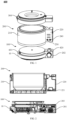
FIG. 10 is a structural schematic view of a pot of the cooking appliance as shown inFIG. 1 . - The present application is further described in detail below in combination with the drawings and embodiments. In particular, the following embodiments are only used to describe the present disclosure, but do not limit the scope of the present disclosure. Similarly, the following embodiments are only part of the present disclosure rather than all of the embodiments. All other embodiments obtained by ordinary technicians in the art without creative work belong to the protection scope of the present disclosure.
- Mentioning "embodiments" herein means that a feature, structure, or characteristic described in conjunction with the embodiments may be included in at least one embodiment of the present disclosure. The appearance of the phrase in various places in the specification does not necessarily refer to the same embodiment, nor is it an independent or alternative embodiment mutually exclusive with other embodiments. Those skilled in the art clearly and implicitly understand that the embodiments described herein may be combined with other embodiments.
- As shown in
FIG. 1, FIG. 1 is a structural schematic view of a cooking appliance according to some embodiments of the present disclosure. Thecooking appliance 600 described in some embodiments of the present disclosure includes apot 200 and aheating assembly 100. Thepot 200 is configured to accommodate food to be cooked. Theheating assembly 100 is configured to heat thepot 200, and thepot 200 is detachably arranged on theheating assembly 100. - In some embodiments, the
heating assembly 100 may include a complete heating and control system, and may be used as a separate heating magnetic furnace to achieve multi-functional product requirement. Theheating assembly 100 may be arranged with a positioning protrusion or convexblock 601, and thepot 200 may be arranged with a positioning groove. The positioning groove is matched with thepositioning protrusion 601, so as to limit a relative position of thepot 200 and theheating assembly 100. - The
pot 200 may further be arranged with afirst control switch 240. Thefirst control switch 240 may be configured to receive a control operation of a user. Thefirst control switch 240 is connected to a control circuit board 30 (as shown inFIG. 6 ) of theheating assembly 100, so as to control theheating assembly 100. - In some embodiments of the present disclosure, the
first control switch 240 of thepot 200 is associated with thecontrol circuit board 30 of theheating assembly 100, that is, by means of establishing a connection between thefirst control switch 240 of thepot 200 and thecontrol circuit board 30 of theheating assembly 100, it is possible to control theheating assembly 100 by operating thefirst control switch 240 of thepot 200, which is more convenient for the user. - In some embodiments, the
heating assembly 100 includes a heating main body and a decorative member sleeved on the heating main body. As shown inFIG. 1 , the heating main body may include aheating body 10 and a side post body 201 (as shown inFIG. 1 , theside post body 201 is covered by adecorative member 202, and theside post body 201 is shown inFIG. 2 ). Theside post body 201 is arranged on an outer wall of theheating body 10. Theheating body 10 is configured to heat thepot 200, and thedecorative member 202 is sleeved on theside post body 201. - Accordingly, the
pot 200 may include apot body 210 and apot side post 220. Thepot body 210 is configured to accommodate the food to be cooked, and is arranged correspondingly to theheating body 10. Thepot side post 220 is connected to an outer wall of thepot body 210, and is arranged correspondingly to or facing theside post body 201. - As shown in
FIG. 1 , thefirst control switch 240 is arranged on thepot side post 220. In some embodiments, thefirst control switch 240 may also be arranged on thepot body 210. In some embodiments, thepot 200 may also not include thepot side post 220, and thefirst control switch 240 is arranged on thepot body 210, which is not limited herein, and which may be selected by those skilled in the art according to actual needs. - In some embodiments, a color of the
pot body 210 may be the same as that of theheating body 10. A color of thepot side post 220 may be the same as that of thedecorative member 202. In addition, the colors of thepot side post 220 and thedecorative member 202 may be different from the colors of thepot body 210 and theheating body 10, such that an appearance color of thecooking appliance 600 may be more eye-catching. Of course, the colors of these components are not limited herein, and may be selected by those skilled in the art according to actual needs. - As shown in
FIG. 1 , thecooking appliance 600 may further include apot cover assembly 300. In some embodiments, thedecorative member 202, thepot side post 220, and an outer shell of thepot cover assembly 300 may have the same color scheme, so as to visually connect theentire cooking appliance 600 as a whole and form the visual tone of the entire product. - In some embodiments, the
pot 200 is arranged with anelectrical component 230, such as an indicator light, a temperature sensor, etc. As shown inFIG. 1 , theelectrical component 230 may be arranged on thepot side post 220. In some embodiments, theelectrical component 230 may also be arranged on thepot body 210. In some embodiments, some of theelectrical component 230 may be arranged on thepot side post 220, and others of theelectrical component 230 may be arranged on thepot body 210, which is not limited herein, and which may be selected by those skilled in the art according to actual needs. - As shown in
FIG. 2, FIG. 2 is a schematic sectional view of the cooking appliance shown inFIG. 1 . A transmittingcoil board 203 is arranged on a side of theside post body 201 close to or adjacent to thepot side post 220. A receivingcoil board 221 is arranged on a side of thepot side post 220 close to or adjacent to theside post body 201. The receivingcoil board 221 cooperates with the transmittingcoil board 203, so as to supply power to theelectrical component 230 of thepot 200. - In some embodiments, the transmitting
coil board 203 may be electrically connected to the power supply (not shown) of theheating assembly 100. The power supply provides high-frequency AC (alternating current) power to the transmittingcoil board 203. Under the action of the high-frequency AC power, the transmittingcoil board 203 may be capable of generating an alternating electromagnetic field that acts on the receivingcoil board 221, such that an alternating current may be generated by the receivingcoil board 221. The receivingcoil board 221 is connected to theelectrical component 230 of the pot 200 (such as the indicator light, the temperature sensor, etc.), so as to input current to theelectrical component 230 of thepot 200, thereby enabling theelectrical component 230 to work normally. That is, wireless power supply of theelectrical component 230 of thepot 200 is achieved by means of arranging the transmittingcoil board 203 on theside post body 201 and arranging the receivingcoil board 221 on thepot side post 220. - As shown in
FIG. 6, FIG. 6 is a partial structural schematic view of the heating assembly of the cooking appliance shown inFIG. 1 . A sinkinggroove 20111 is defined on a side surface of theside post body 201 close to thepot side post 220, and is configured to accommodate the transmittingcoil board 203. Thedecorative member 202 is sleeved on theside post body 201, and is configured to fix the transmittingcoil board 203 in the sinkinggroove 20111. In some embodiments, a size of the sinkinggroove 20111 may be matched with a size of the transmittingcoil board 203, such that the transmittingcoil board 203 may be completely limited and unable to move. The assembly solution may omit a screw, a fastener, and other connection structures, such that a structure of theside post body 201 is simplified, and it facilities improving the assembly efficiency of the product. - In some embodiments, the heating main body may not include the
side post body 201. The sinkinggroove 20111 may be arranged on a side surface of theheating body 10 close to thepot 200, the transmittingcoil board 203 may be arranged in the sinking groove, and the decorative member may be sleeved on theentire heating body 10 to fix the transmitting coil board in the sinking groove. - In some embodiments, the
heating assembly 100 may also not include thedecorative member 202, and the transmittingcoil board 203 may be fixed to theside post body 201 via a connecting structure such as a screw, a fastener, etc., which is not limited herein, and which may be selected by those skilled in the art according to actual needs. - In some embodiments, the
first control switch 240 is configured to receive the control operation of the user and generate a corresponding electrical signal. In some embodiments, thefirst control switch 240 may be configured to generate the corresponding electrical signal when touched by the user, or thefirst control switch 240 may generate the corresponding electrical signal when pressed by the user, or thefirst control switch 240 may generate the corresponding electrical signal when rotated by the user, which is not limited herein, and which may be selected by those skilled in the art according to actual needs. - As shown in
FIG. 3, FIG. 3 is another schematic sectional view of the cooking appliance shown inFIG. 1 . The receivingcoil board 221 is electrically connected to thefirst control switch 240, such as by means of a wire. The transmittingcoil board 203 is electrically connected to thecontrol circuit board 30 of theheating assembly 100, such as by means of a wire. The receivingcoil board 221 cooperates or operates with the transmittingcoil board 203, so as to transmit the electrical signal generated by thefirst control switch 240 and corresponding to the control operation of the user to thecontrol circuit board 30 of theheating assembly 100. - As shown in
FIGS. 1 and3 , thefirst control switch 240 may include afirst touch key 241, afirst touch spring 242, and atouch circuit board 243. Thefirst touch key 241 is arranged on a surface of thepot 200, such as a surface of thepot side post 220. Thefirst touch key 241 is configured to receive the control operation of the user and generate the electrical signal corresponding to the control operation of the user. In some embodiments, thefirst touch key 241 may be a capacitive touch switch or a resistive touch switch. Thefirst touch spring 242 and thetouch circuit board 243 may be arranged inside thepot side post 220. One end of thefirst touch spring 242 is electrically connected to thefirst touch key 241, and the other end of thefirst touch spring 242 is electrically connected to thetouch circuit board 243, so as to transmit the electrical signal generated by thefirst touch key 241 and corresponding to the control operation of the user to thetouch circuit board 243. - The
touch circuit board 243 is electrically connected to the receivingcoil board 221. Thetouch circuit board 243 is connected to the receivingcoil board 221, such as by means of a wire. Thetouch circuit board 243 is configured to amplify the electrical signal generated by thefirst touch key 241 and corresponding to the control operation of the user, and transmit an amplified electrical signal to the receivingcoil board 221. - Under the action of the amplified electrical signal, the receiving
coil board 221 generates an induced magnetic field that acts on the transmittingcoil board 203, such that an induced current corresponding to the electrical signal may be generated by the transmittingcoil board 203. The transmittingcoil board 203 transmits a corresponding induced current to thecontrol circuit board 30 of theheating assembly 100, so as to control theheating assembly 100. - In some embodiments, the
first control switch 240 may not include thefirst touch spring 242. Thetouch key 241 may be electrically connected to thetouch circuit board 243 by means of a conductor in any form. In an embodiment, thefirst touch key 241 is directly welded on thetouch circuit board 243, which is not limited herein, and which may be selected by those skilled in the art according to actual needs. - As mentioned above, the transmitting
coil board 203 may be connected to thecontrol circuit board 30 of theheating assembly 100 via a circuit. As further shown inFIG. 6 , a terminal 2031 is arranged on a side of the transmittingcoil board 203 close to the receivingcoil board 221. The terminal 2031 is arranged on an end of the transmittingcoil board 203 close to theheating body 10. The transmittingcoil board 203 is connected to thecontrol circuit board 30 of theheating assembly 10 via theterminal 2031. - In some embodiments, the sinking
groove 20111 may be further arranged with a support member. The support member is configured to support the transmittingcoil board 203, such that a side of the transmittingcoil board 203 away from theheating body 10 may be inclined to a direction close to or facing the receivingcoil board 221. - As mentioned above, the terminal 2031 is arranged on a side surface of the transmitting
coil board 203 close to the receivingcoil board 221, and is arranged on a side of the transmittingcoil board 203 close to theheating body 10. Due to a certain height of the terminal 2031 (i.e., the height thereof is generally in a range from 10mm to 20mm), if the transmittingcoil board 203 is substantially arranged parallel to the receivingcoil board 221, a distance between the transmittingcoil board 203 and the receivingcoil board 221 cannot be further reduced due to presence/existence of the terminal 2031, resulting in affecting cooperation between the transmittingcoil board 203 and the receivingcoil board 221. By arranging the support member in the sinkinggroove 20111, the side of the transmittingcoil board 203 away from theheating body 10 may be inclined to the direction close to the receivingcoil board 221, which facilitates reducing the distance between the transmittingcoil board 203 and the receivingcoil board 221, thereby ensuring working performance of the transmittingcoil board 203 and the receivingcoil board 221. - In some embodiments, two
support ribs 20112 are arranged at intervals on a bottom of the sinkinggroove 20111. The twosupport ribs 20112 may be served as the above-mentioned support member and configured to support the transmittingcoil board 203. The twosupport ribs 20112 extend in a direction away from theheating body 10, and a height of each of the twosupport ribs 20112 gradually increases, such that the side of the transmittingcoil board 203 away from theheating body 10 may be inclined to the direction close to the receivingcoil board 221. - In some embodiments, one
support rib 20112 may further be arranged on a side of the bottom of the sinkinggroove 20111 away from theheating body 10, such that the side of the transmittingcoil board 203 close to theheating body 10 may abut against the bottom of the sinkinggroove 20111, and the side of the transmittingcoil board 203 away from theheating body 10 is arranged on thesupport rib 20112. In this way, the side of the transmittingcoil board 203 away from theheating body 10 may be inclined to the direction close to the receivingcoil board 221. By arranging thesupport rib 20112, a gap is defined between the bottom of the sinkinggroove 20111 and the transmittingcoil board 203, which facilitates dissipating heat for the transmittingcoil board 203. - In some embodiments, the bottom of the sinking
groove 20111 may also be arranged as an inclined surface, such that the side of the transmittingcoil board 203 away from theheating body 10 may be inclined to the direction close to the receivingcoil board 221. - In addition, the transmitting
coil board 203 cooperates with the receivingcoil board 221, and is further configured to transmit a temperature signal detected by the temperature sensor of thepot 200. In some embodiments, the temperature sensor is configured to monitor temperature inside thepot 200 in real-time, convert the temperature signal into an electrical signal, generate the alternating current via the receiving coil board, and generate the alternating magnetic field. A corresponding induced current may be generated by the transmittingcoil board 203 of theside post body 201 under the action of the alternating magnetic field. Then, a chip of thecircuit board 30 is controlled to decode the induced current, and convert the induced current into the temperature signal inside thepot 200, thereby controlling theheating body 10 based on the temperature signal. - The
control circuit board 30 may control theheating body 10 based on the temperature inside thepot 200. In some embodiments, when the temperature inside thepot 200 is lower than a first threshold, thecontrol circuit board 30 may turn on theheating body 10 or increase a heating power of theheating body 10, so as to increase the temperature inside thepot 200. When the temperature inside thepot 200 is greater than a second threshold, thecontrol circuit board 30 may turn off theheating body 10 or reduce the heating power of theheating body 10, so as to decrease the temperature inside thepot 200. - In some embodiments, the value range of the first threshold may be from 80°C to 120°C, such as 80°C, 90°C, 100°C, 110°C, and 120°C, etc. The value range of the second threshold may be from 120 to 160°C, such as 120°C, 130°C, 140°C, 150°C, and 160°C, etc. A value of the first threshold and a value of the second threshold are not limited herein, which may be selected by those skilled in the art according to actual needs.
- Of course, the above description of controlling the
heating body 10 by thecontrol circuit board 30 is only an example, and is not a limitation of the present disclosure. Within the scope easy to understand by those skilled in the art, those skilled in the art can make choices according to actual needs. - The
heating assembly 100 will be described below, which may refer to the description of the heating assembly in the embodiments below for details. - As shown in
FIG. 4, FIG. 4 is a structural schematic view of a heating assembly of the cooking appliance shown inFIG. 1 . In some embodiments, theheating assembly 100 includes a heating main body and a decorative member sleeved on the heating main body. The heating main body may include theheating body 10 and theside post body 201. Thedecorative member 202 is sleeved on theside post body 201. - As shown in
FIG. 4 , theheating body 10 and theside post body 201 may be integrally formed. Of course, in some embodiments, theheating body 10 and theside post body 201 may also be arranged separately or independently or individually, or theheating body 10 and theside post body 201 is two individual parts. However, in case that theheating body 10 and theside post body 201 are arranged separately, the product has a poor product reliability and the following problems such as waterproofing, safety regulations, creepage distance, and structural strength may occur. Especially in terms of waterproofing, regardless of an assembly method for arranging theheating body 10 and theside post body 201, there will be a problem that water enters inside of the product along an assembly gap between theheating body 10 and theside post body 201, leading to damage or failure of the product function. - In a case that the
heating body 10 and theside post body 201 are integrally formed, it facilitates improving an appearance effect of theheating assembly 100 by arranging thedecorative member 202. A reason is that thedecorative member 202 is arranged to enable theheating body 10 and the side post (including theside post body 201 and decorative member 202) to have different colors. Without thedecorative member 202, it is difficult to realize dual-color injection molding of theheating body 10 and theside post body 201 due to the limitation of an existing technological process. - The
heating assembly 100 may be a heating magnetic furnace. Theheating body 10 may be arranged in a circular shape. Theside post body 201 extends outward from the outer wall of theheating body 10. In some embodiments, theheating body 10 may also be arranged in a square shape, which is not limited herein, and which may be selected by those skilled in the art according to actual needs. - A structure of the
heating body 10 is shown inFIG. 5, and FIG. 5 is an exploded structural schematic view of the heating assembly shown inFIG. 4 . Theheating body 10 includes ahousing 101, apanel 102, and aheating source 103. Theside post body 201 and thehousing 101 are integrally formed. Thepanel 102 is covered on thehousing 101. Thepanel 102 and thehousing 101 cooperatively define an accommodating space to accommodate theheating source 103. In some embodiments, theheating source 103 may be a coil, which is not limited herein, and which may be selected by those skilled in the art according to actual needs. - The
housing 101 may include amiddle frame 1011 and abase 1012. As shown inFIG. 5 , themiddle frame 1011 and thebase 1012 may be arranged separately. Thebase 1012 and thepanel 102 are respectively arranged on two sides of themiddle frame 1011. - Accordingly, the
side post body 201 may include a firstside post body 2011 and a secondside post body 2012. As shown inFIG. 5 , the firstside post body 2011 and the secondside post body 2012 may be arranged separately. In some embodiments, the firstside post body 2011 and themiddle frame 1011 may be integrally formed. The secondside post body 2012 and thebase 1012 may be integrally formed. - In some embodiments, the
middle frame 1011 and thebase 1012 may be integrally formed. Accordingly, the firstside post body 2011 and the secondside post body 2012 may also be integrally formed, which is not limited herein, and which may be selected by those skilled in the art according to actual needs. - As shown in
FIGS. 5 and 7, FIG. 7 is a structural schematic view of a control circuit board of the heating assembly shown inFIG. 5 . Thecontrol circuit board 30 of theheating assembly 100 is disposed in theside post body 201 and extends out of theside post body 201, so as to control theheating body 10. - In some embodiments, the first
side post body 2011 and the secondside post body 2012 may cooperatively define an accommodating cavity (not shown). Thecontrol circuit board 30 may be arranged in the accommodating cavity defined by the firstside post body 2011 and the secondside post body 2012. At least a part of a structure of thecontrol circuit board 30 extends into theheating body 10, so as to control theheating body 10. - In some embodiments, the
heating assembly 100 may further include asecond control switch 420 electrically connected to thecontrol circuit board 30. Thefirst control switch 240 is connected to thesecond control switch 420. - In some embodiments, the
first control switch 240 may be electrically connected to thesecond control switch 420. Thefirst control switch 240 is configured to receive the control operation of the user and generate the corresponding electrical signal. Thesecond control switch 420 is configured to receive the electrical signal generated by thefirst control switch 240 and transmit the electrical signal to thecontrol circuit board 30 of theheating assembly 100, so as to control theheating assembly 100. - As shown in
FIG. 8, FIG. 8 is another schematic sectional view of the cooking appliance shown inFIG. 1 . Thepot 200 may further include atransmission conductor 410. In some embodiments, thetransmission conductor 410 may be arranged inside thepot side post 220. Thesecond control switch 420 is arranged on theheating assembly 100 and electrically connected to thecontrol circuit board 30 of theheating assembly 100. Thefirst control switch 240 is electrically connected to thesecond control switch 420 via thetransmission conductor 410. - As shown in
FIGS. 1 and8 , thefirst control switch 240 may include thefirst touch key 241 and thefirst touch spring 242. Thefirst touch key 241 is arranged on the surface of thepot 200, such as the surface of thepot side post 220. Thefirst touch key 241 is configured to receive the control operation of the user and generate the electrical signal corresponding to the control operation of the user. In some embodiments, thefirst touch key 241 may be the capacitive touch switch or the resistive touch switch. Thefirst touch spring 242 may be arranged inside thepot side post 220. One end of thefirst touch spring 242 is electrically connected to thefirst touch key 241, and the other end of thefirst touch spring 242 is electrically connected to thetransmission conductor 410, so as to transmit the electrical signal generated by thefirst touch key 241 and corresponding to the control operation of the user to thetransmission conductor 410. - The
transmission conductor 410 may be a conductor in any form, such as an aluminum sheet or a wire. A structure and a material of thetransmission conductor 410 are not limited herein, which may be selected by those skilled in the art according to actual needs. - The
second control switch 420 may include a second touch key 421 and a second touch spring 422. The second touch key 421 is arranged on a side surface of theheating assembly 100 close to thepot 200, and is electrically connected to thetransmission conductor 410 to receive the electrical signal from thetransmission conductor 410. In some embodiments, the second touch key 421 may be a capacitive touch switch or a resistive touch switch. As shown inFIG. 8 , the second touch key 421 may be arranged on a side surface of thedecorative member 202 close to thepot side post 220. - The second touch spring 422 may be arranged in the
side post body 201. One end of second touch spring 422 is electrically connected to the second touch key 421, and the other end of the second touch spring 422 is electrically connected to thecontrol circuit board 30 of theheating assembly 100. The second touch spring 422 is configured to transmit the electrical signal received by the second touch key 421 to thecontrol circuit board 30 of theheating assembly 100. Thecontrol circuit board 30 controls theheating body 10 to heat thepot 200 based on the electrical signal. - In some embodiments, the second touch key 421 may be further configured to receive another control operation of the user and generate an electrical signal corresponding to the another control operation of the user.
- In some embodiments, the
transmission conductor 410 may be an elastic member. In a compressed state, thetransmission conductor 410 is capable of generating a certain amount of elastic force. Thetransmission conductor 410 may be pushed towards the second touch key 421 of theheating assembly 100 via the elastic force, which facilitates ensuring a reliable connection between thetransmission conductor 410 and the second touch key 421. - As shown in
FIGS. 1 and9, FIG. 9 is another schematic sectional view of the cooking appliance shown inFIG. 1 . In some embodiments, thefirst control switch 240 is a touch conductor. The touch conductor is capable of generating the electrical signal when touched by a human body. In some embodiments, the touch conductor may be a conductor in any form, such as an aluminum sheet or a copper sheet, as long as the conductor is capable of conducting electricity. A structure and a material of the touch conductor are not limited herein, which may be selected by those skilled in the art according to actual needs. - One end of the touch conductor is arranged on the surface of the
pot 200, and is configured to receive the control operation of the user and generate the electrical signal corresponding to the control operation of the user. The other end of the touch conductor is electrically connected to thetransmission conductor 410, so as to transmit the generated electrical signal to thetransmission conductor 410. - In some embodiments, the
first control switch 240 may also be a mechanical structure switch. The pot may further include a transmission member (not shown). In response to the control operation of the user, thefirst control switch 240 is configured to drive the transmission member to trigger thesecond control switch 420, so as to control theheating assembly 100. In some embodiments, thesecond control switch 420 is a touch switch or a membrane switch. thesecond control switch 420 is welded on thecontrol circuit board 30. Under the force applied by the user, thefirst control switch 240 is configured to drive the transmission member to trigger thesecond control switch 420. - A structure of the
pot 200 may be further described below. As shown inFIG. 10, FIG. 10 is a structural schematic view of a pot of the cooking appliance shown inFIG. 1 . - In some embodiments, the
pot body 210 may include aninner liner 211, anouter shell 212, asupport base 213, and anouter shell cover 214. In some embodiments, theinner liner 211 is configured to accommodate the food to be cooked. Thepedestal 213 and theouter shell 212 cooperatively define an accommodating space. Theinner liner 211 is fixed in the accommodating space defined by thepedestal 213 and theouter shell 212 via theouter shell cover 214. Theouter shell 212 and thepedestal 213 may be made of an insulation material, such that it may be possible to allow the user to place thepot 200 on a dining table after cooking, and prevent the table and the user from being scalding. - Terms "first", "second", and "third" in the present disclosure are used for descriptive purposes only, and shall not be interpreted as indicating or implying relative importance or implicitly specifying the number of an indicated technical feature. Therefore, a feature defined by the terms "first", "second", and "third" may explicitly or implicitly include at least one such feature. In the description of the present disclosure, "a plurality of' means at least two, such as two, three, and so on, unless otherwise expressly and specifically limited. All directional indications (such as up, down, left, right, forward, backward...) in the present disclosure are used only to explain relative positions and movements of components in a particular attitude (the attitude shown in the corresponding drawing). When the particular attitude is changed, the directional indications may be changed accordingly. Terms "include", "have", and any variation thereof, are intended to cover non-exclusive inclusion. For example, a process, a method, a system, a product or an apparatus including a series of operations or units is not limited to the listed operations or units, but may further include operations or units that are not listed, or may include other may or units that are inherently included in the process, the method, the product or the apparatus.
- The above is only some embodiments of the present disclosure, not to limit the scope of the present disclosure. Any equivalent structure or equivalent process transformation made by using the contents of the specification and the accompanying drawings of the present disclosure, or directly or indirectly applied in other related technical fields, are included in the scope of the present disclosure in the same way.
Claims (13)
- A cooking appliance, characterized by comprising:a pot, comprising a first control switch; anda heating assembly, configured to heat the pot and comprising a control circuit board, wherein the heating assembly and the pot are arranged separately;wherein the first control switch is associated with the control circuit board, and the heating assembly is controlled.
- The cooking appliance according to claim 1, wherein the heating assembly further comprises a second control switch electrically connected to the control circuit board, and the first control switch is connected to the second control switch.
- The cooking appliance according to claim 2, wherein the pot further comprises a transmission conductor, and the first control switch is electrically connected to the second control switch via the transmission conductor.
- The cooking appliance according to claim 3, wherein the first control switch comprises:a first touch key, arranged on a surface of the pot;a first touch spring, wherein an end of the first touch spring is electrically connected to the first touch key, and the other end of the first touch spring is electrically connected to the transmission conductor.
- The cooking appliance according to claim 3, wherein the first control switch comprises a touch conductor, one end of the touch conductor is arranged on a surface of the pot, and the other end of the touch conductor is electrically connected to the transmission conductor.
- The cooking appliance according to claim 3, wherein the second control switch comprises:a second touch key, arranged on a side surface of the heating assembly close to the pot and electrically connected to the transmission conductor; anda second touch spring, wherein one end of the second touch spring is electrically connected to the second touch key, and the other end of the second touch spring is electrically connected to the control circuit board.
- The cooking appliance according to claim 2, wherein the pot further comprises a transmission member;
in response to a control operation of a user, the first control switch is configured to drive the transmission member to trigger the second control switch, and the heating assembly is controlled. - The cooking appliance according to claim 7, wherein the second control switch is a touch switch or a membrane switch, and the second control switch is welded on the control circuit board.
- The cooking appliance according to claim 1, wherein the pot further comprises a receiving coil board electrically connected to the first control switch;the heating assembly further comprises a transmitting coil board electrically connected to the control circuit board; andthe transmitting coil board cooperates with the receiving coil board, such that the first control switch is connected to the control circuit board.
- The cooking appliance according to claim 9, wherein the first control switch comprises:a first touch key, arranged on a surface of the pot, and configured to receive a control operation of a user and generate a corresponding electrical signal; anda first touch spring, one end of the first touch spring being electrically connected to the first touch key; anda touch circuit board, electrically connected to the other end of the first touch spring, wherein the touch circuit board is electrically connected to the receiving coil board, and the touch circuit board is configured to amplify the electrical signal and transmit an amplified electrical signal to the receiving coil board.
- The cooking appliance according to claim 9, wherein the transmitting coil board cooperates with the receiving coil board and is further configured to supply power to an electrical component of the pot.
- The cooking appliance according to claim 9, wherein the heating assembly comprises:a heating main body, wherein a side of the heating main body close to the pot defines a sinking groove, and the transmitting coil board is arranged in the sinking groove; anda decorative member, sleeved on the heating main body and configured to fix the transmitting coil board in the sinking groove.
- The cooking appliance according to claim 1, wherein the heating assembly comprises a heating body, a side post body, and a decorative member, the side post body is arranged on a sidewall of the heating body, and the decorative member is sleeved on the side post body; and
the pot comprises a pot body and a pot side post, the pot body is arranged correspondingly to the heating body, the pot side post is arranged correspondingly to the side post body, and the first control switch is arranged on the pot side post.
Applications Claiming Priority (2)
| Application Number | Priority Date | Filing Date | Title |
|---|---|---|---|
| CN202120794597.7U CN215127468U (en) | 2021-04-16 | 2021-04-16 | Cooking utensil |
| PCT/CN2021/113885 WO2022217801A1 (en) | 2021-04-16 | 2021-08-20 | Cooking appliance |
Publications (2)
| Publication Number | Publication Date |
|---|---|
| EP4324363A1 true EP4324363A1 (en) | 2024-02-21 |
| EP4324363A4 EP4324363A4 (en) | 2024-10-30 |
Family
ID=79360598
Family Applications (1)
| Application Number | Title | Priority Date | Filing Date |
|---|---|---|---|
| EP21936673.9A Pending EP4324363A4 (en) | 2021-04-16 | 2021-08-20 | COOKING APPLIANCE |
Country Status (4)
| Country | Link |
|---|---|
| EP (1) | EP4324363A4 (en) |
| KR (1) | KR20230170742A (en) |
| CN (1) | CN215127468U (en) |
| WO (1) | WO2022217801A1 (en) |
Family Cites Families (11)
| Publication number | Priority date | Publication date | Assignee | Title |
|---|---|---|---|---|
| JP2000323270A (en) * | 1999-05-12 | 2000-11-24 | Hitachi Hometec Ltd | Electromagnetic cooker |
| CN101589909A (en) * | 2009-06-19 | 2009-12-02 | 任传强 | Automatic functional split combined rare-oil smoke electric cooker |
| CN102178449B (en) * | 2011-04-30 | 2013-10-23 | 浙江苏泊尔家电制造有限公司 | electric heating cooking device |
| CN204427623U (en) * | 2015-02-06 | 2015-07-01 | 佛山市顺德区美的电热电器制造有限公司 | Electromagnetic stove |
| US10444080B2 (en) * | 2015-11-17 | 2019-10-15 | Haier Us Appliance Solutions, Inc. | Thermal management for a wireless cooking probe |
| CN206137862U (en) * | 2016-07-20 | 2017-05-03 | 佛山市顺德区美的电热电器制造有限公司 | Intelligence culinary art controlling means |
| CN208435211U (en) * | 2017-08-16 | 2019-01-29 | 佛山市顺德区美的电热电器制造有限公司 | Split cooking apparatus |
| CN208435216U (en) * | 2017-10-24 | 2019-01-29 | 佛山市顺德区美的电热电器制造有限公司 | Split cooking apparatus |
| CN108808880B (en) * | 2018-06-22 | 2025-06-06 | 广东美的厨房电器制造有限公司 | Magnetic knobs and electrical equipment |
| EP3698681B1 (en) * | 2019-02-20 | 2021-11-17 | LG Electronics Inc. | Wireless induction heating cooker and wireless induction heating system including same |
| CN112336164B (en) * | 2019-08-09 | 2022-09-09 | 佛山市顺德区美的电热电器制造有限公司 | Knob assembly and cooking utensil |
-
2021
- 2021-04-16 CN CN202120794597.7U patent/CN215127468U/en not_active Expired - Fee Related
- 2021-08-20 WO PCT/CN2021/113885 patent/WO2022217801A1/en not_active Ceased
- 2021-08-20 KR KR1020237039038A patent/KR20230170742A/en active Pending
- 2021-08-20 EP EP21936673.9A patent/EP4324363A4/en active Pending
Also Published As
| Publication number | Publication date |
|---|---|
| EP4324363A4 (en) | 2024-10-30 |
| WO2022217801A1 (en) | 2022-10-20 |
| KR20230170742A (en) | 2023-12-19 |
| CN215127468U (en) | 2021-12-14 |
Similar Documents
| Publication | Publication Date | Title |
|---|---|---|
| JP7138705B2 (en) | table cooker | |
| JP2018509585A (en) | Separate microwave oven | |
| EP0202864A2 (en) | Remote control of electrical heating appliances | |
| KR102641091B1 (en) | Induction heating device having improved insulation structure | |
| CN213820959U (en) | Separate cooking utensils | |
| KR102651222B1 (en) | Induction heating device having improved component layout structure and assemblability | |
| CN215127468U (en) | Cooking utensil | |
| JP2005265208A (en) | Built-in cooking device | |
| CN203434393U (en) | Electric food warmer control plug | |
| CN203207778U (en) | Electric rice cooker | |
| JP2017174531A (en) | Induction heating cooker | |
| CN212845849U (en) | Detection circuit and electromagnetic heating equipment | |
| CN215127143U (en) | Heating assembly and cooking utensil | |
| CN218897303U (en) | Power supply controller and heating type electric appliance | |
| CN222395840U (en) | Cooking utensil circuit board assembly and cooking utensil | |
| CN210007924U (en) | Wireless communication device for cooking appliance and cooking appliance | |
| CN202886874U (en) | Separated type control device of electric oven | |
| CN215723392U (en) | Commercial induction cooker | |
| CN218954946U (en) | Cooking utensil | |
| CN220067710U (en) | Power supply controller and heating type electric appliance | |
| CN209863274U (en) | Circuit board assembly for household appliance and cooking utensil | |
| CN214387159U (en) | Pot and cooking utensil | |
| CN217013653U (en) | Combined multifunctional cooking equipment | |
| CN214949240U (en) | Cooking utensil | |
| CN210727502U (en) | Safety structure of electric cooking device |
Legal Events
| Date | Code | Title | Description |
|---|---|---|---|
| STAA | Information on the status of an ep patent application or granted ep patent |
Free format text: STATUS: THE INTERNATIONAL PUBLICATION HAS BEEN MADE |
|
| PUAI | Public reference made under article 153(3) epc to a published international application that has entered the european phase |
Free format text: ORIGINAL CODE: 0009012 |
|
| STAA | Information on the status of an ep patent application or granted ep patent |
Free format text: STATUS: REQUEST FOR EXAMINATION WAS MADE |
|
| 17P | Request for examination filed |
Effective date: 20231114 |
|
| AK | Designated contracting states |
Kind code of ref document: A1 Designated state(s): AL AT BE BG CH CY CZ DE DK EE ES FI FR GB GR HR HU IE IS IT LI LT LU LV MC MK MT NL NO PL PT RO RS SE SI SK SM TR |
|
| DAV | Request for validation of the european patent (deleted) | ||
| DAX | Request for extension of the european patent (deleted) | ||
| A4 | Supplementary search report drawn up and despatched |
Effective date: 20241002 |
|
| RIC1 | Information provided on ipc code assigned before grant |
Ipc: A47J 36/32 20060101ALI20240926BHEP Ipc: A47J 27/00 20060101ALI20240926BHEP Ipc: A47J 36/24 20060101AFI20240926BHEP |