EP4324342A1 - Medium segment, aerosol-generating article, and system comprising same - Google Patents
Medium segment, aerosol-generating article, and system comprising same Download PDFInfo
- Publication number
- EP4324342A1 EP4324342A1 EP22916349.8A EP22916349A EP4324342A1 EP 4324342 A1 EP4324342 A1 EP 4324342A1 EP 22916349 A EP22916349 A EP 22916349A EP 4324342 A1 EP4324342 A1 EP 4324342A1
- Authority
- EP
- European Patent Office
- Prior art keywords
- segment
- wrapper
- medium
- aerosol generating
- exothermic
- Prior art date
- Legal status (The legal status is an assumption and is not a legal conclusion. Google has not performed a legal analysis and makes no representation as to the accuracy of the status listed.)
- Pending
Links
Images


Classifications
-
- H—ELECTRICITY
- H05—ELECTRIC TECHNIQUES NOT OTHERWISE PROVIDED FOR
- H05B—ELECTRIC HEATING; ELECTRIC LIGHT SOURCES NOT OTHERWISE PROVIDED FOR; CIRCUIT ARRANGEMENTS FOR ELECTRIC LIGHT SOURCES, IN GENERAL
- H05B6/00—Heating by electric, magnetic or electromagnetic fields
- H05B6/02—Induction heating
- H05B6/10—Induction heating apparatus, other than furnaces, for specific applications
- H05B6/105—Induction heating apparatus, other than furnaces, for specific applications using a susceptor
- H05B6/108—Induction heating apparatus, other than furnaces, for specific applications using a susceptor for heating a fluid
-
- A—HUMAN NECESSITIES
- A24—TOBACCO; CIGARS; CIGARETTES; SIMULATED SMOKING DEVICES; SMOKERS' REQUISITES
- A24D—CIGARS; CIGARETTES; TOBACCO SMOKE FILTERS; MOUTHPIECES OF CIGARS OR CIGARETTES; MANUFACTURE OF TOBACCO SMOKE FILTERS OR MOUTHPIECES
- A24D1/00—Cigars; Cigarettes
- A24D1/20—Cigarettes specially adapted for simulated smoking devices
-
- A—HUMAN NECESSITIES
- A24—TOBACCO; CIGARS; CIGARETTES; SIMULATED SMOKING DEVICES; SMOKERS' REQUISITES
- A24D—CIGARS; CIGARETTES; TOBACCO SMOKE FILTERS; MOUTHPIECES OF CIGARS OR CIGARETTES; MANUFACTURE OF TOBACCO SMOKE FILTERS OR MOUTHPIECES
- A24D1/00—Cigars; Cigarettes
- A24D1/02—Cigars; Cigarettes with special covers
-
- A—HUMAN NECESSITIES
- A24—TOBACCO; CIGARS; CIGARETTES; SIMULATED SMOKING DEVICES; SMOKERS' REQUISITES
- A24D—CIGARS; CIGARETTES; TOBACCO SMOKE FILTERS; MOUTHPIECES OF CIGARS OR CIGARETTES; MANUFACTURE OF TOBACCO SMOKE FILTERS OR MOUTHPIECES
- A24D1/00—Cigars; Cigarettes
- A24D1/02—Cigars; Cigarettes with special covers
- A24D1/025—Cigars; Cigarettes with special covers the covers having material applied to defined areas, e.g. bands for reducing the ignition propensity
-
- A—HUMAN NECESSITIES
- A24—TOBACCO; CIGARS; CIGARETTES; SIMULATED SMOKING DEVICES; SMOKERS' REQUISITES
- A24D—CIGARS; CIGARETTES; TOBACCO SMOKE FILTERS; MOUTHPIECES OF CIGARS OR CIGARETTES; MANUFACTURE OF TOBACCO SMOKE FILTERS OR MOUTHPIECES
- A24D1/00—Cigars; Cigarettes
- A24D1/04—Cigars; Cigarettes with mouthpieces or filter-tips
- A24D1/045—Cigars; Cigarettes with mouthpieces or filter-tips with smoke filter means
-
- A—HUMAN NECESSITIES
- A24—TOBACCO; CIGARS; CIGARETTES; SIMULATED SMOKING DEVICES; SMOKERS' REQUISITES
- A24D—CIGARS; CIGARETTES; TOBACCO SMOKE FILTERS; MOUTHPIECES OF CIGARS OR CIGARETTES; MANUFACTURE OF TOBACCO SMOKE FILTERS OR MOUTHPIECES
- A24D1/00—Cigars; Cigarettes
- A24D1/22—Cigarettes with integrated combustible heat sources, e.g. with carbonaceous heat sources
-
- A—HUMAN NECESSITIES
- A24—TOBACCO; CIGARS; CIGARETTES; SIMULATED SMOKING DEVICES; SMOKERS' REQUISITES
- A24D—CIGARS; CIGARETTES; TOBACCO SMOKE FILTERS; MOUTHPIECES OF CIGARS OR CIGARETTES; MANUFACTURE OF TOBACCO SMOKE FILTERS OR MOUTHPIECES
- A24D3/00—Tobacco smoke filters, e.g. filter tips or filtering inserts; Filters specially adapted for simulated smoking devices; Mouthpieces of cigars or cigarettes
- A24D3/02—Manufacture of tobacco smoke filters
- A24D3/0275—Manufacture of tobacco smoke filters for filters with special features
- A24D3/0279—Manufacture of tobacco smoke filters for filters with special features with tubes
-
- A—HUMAN NECESSITIES
- A24—TOBACCO; CIGARS; CIGARETTES; SIMULATED SMOKING DEVICES; SMOKERS' REQUISITES
- A24D—CIGARS; CIGARETTES; TOBACCO SMOKE FILTERS; MOUTHPIECES OF CIGARS OR CIGARETTES; MANUFACTURE OF TOBACCO SMOKE FILTERS OR MOUTHPIECES
- A24D3/00—Tobacco smoke filters, e.g. filter tips or filtering inserts; Filters specially adapted for simulated smoking devices; Mouthpieces of cigars or cigarettes
- A24D3/17—Filters specially adapted for simulated smoking devices
-
- A—HUMAN NECESSITIES
- A24—TOBACCO; CIGARS; CIGARETTES; SIMULATED SMOKING DEVICES; SMOKERS' REQUISITES
- A24F—SMOKERS' REQUISITES; MATCH BOXES; SIMULATED SMOKING DEVICES
- A24F40/00—Electrically operated smoking devices; Component parts thereof; Manufacture thereof; Maintenance or testing thereof; Charging means specially adapted therefor
- A24F40/40—Constructional details, e.g. connection of cartridges and battery parts
- A24F40/46—Shape or structure of electric heating means
- A24F40/465—Shape or structure of electric heating means specially adapted for induction heating
-
- H—ELECTRICITY
- H05—ELECTRIC TECHNIQUES NOT OTHERWISE PROVIDED FOR
- H05B—ELECTRIC HEATING; ELECTRIC LIGHT SOURCES NOT OTHERWISE PROVIDED FOR; CIRCUIT ARRANGEMENTS FOR ELECTRIC LIGHT SOURCES, IN GENERAL
- H05B6/00—Heating by electric, magnetic or electromagnetic fields
- H05B6/02—Induction heating
- H05B6/06—Control, e.g. of temperature, of power
-
- H—ELECTRICITY
- H05—ELECTRIC TECHNIQUES NOT OTHERWISE PROVIDED FOR
- H05B—ELECTRIC HEATING; ELECTRIC LIGHT SOURCES NOT OTHERWISE PROVIDED FOR; CIRCUIT ARRANGEMENTS FOR ELECTRIC LIGHT SOURCES, IN GENERAL
- H05B6/00—Heating by electric, magnetic or electromagnetic fields
- H05B6/02—Induction heating
- H05B6/10—Induction heating apparatus, other than furnaces, for specific applications
- H05B6/105—Induction heating apparatus, other than furnaces, for specific applications using a susceptor
-
- A—HUMAN NECESSITIES
- A24—TOBACCO; CIGARS; CIGARETTES; SIMULATED SMOKING DEVICES; SMOKERS' REQUISITES
- A24F—SMOKERS' REQUISITES; MATCH BOXES; SIMULATED SMOKING DEVICES
- A24F40/00—Electrically operated smoking devices; Component parts thereof; Manufacture thereof; Maintenance or testing thereof; Charging means specially adapted therefor
- A24F40/20—Devices using solid inhalable precursors
Definitions
- the following description relates to a medium segment, an aerosol generating article, and a system including the aerosol generating article.
- Aerosol generating devices that generate an aerosol in a non-burning manner from an aerosol generating article (e.g., a cigarette) are being developed.
- an aerosol generating article e.g., a cigarette
- Korean Patent Publication No. 10-2019-0119465 discloses an aerosol generating device.
- the above description is information acquired during the course of conceiving the present disclosure, or already possessed at the time, and is not necessarily art publicly known before the present application was filed.
- One aspect of the present disclosure may provide a medium segment that may increase the heating efficiency of the medium, an aerosol generating article, and a system including the aerosol generating article.
- a medium segment for an aerosol generating article includes a medium, an exothermic wrapper including a heat source and surrounding the medium, and a thermal insulating wrapper surrounding the exothermic wrapper.
- the thermal insulating wrapper may have a basis weight of about 40 grams per square meter (g/m 2 ) to about 80 g/m 2 .
- the thermal insulating wrapper may have a thickness of about 60 micrometers ( ⁇ m) to about 120 ⁇ m.
- the exothermic wrapper may further include a first wrapper surrounding the medium, and a second wrapper surrounding the first wrapper, wherein the heat source may be disposed between the first wrapper and the second wrapper.
- the exothermic wrapper may further include a wrapper surrounding the medium, and the heat source may be disposed between the medium and the wrapper or outside the wrapper.
- the heat source may include a susceptor material.
- an aerosol generating article includes a first segment including a filter, and a second segment disposed downstream of the first segment, wherein the second segment may include a medium segment, wherein the medium segment may include a medium, an exothermic wrapper including a heat source and surrounding the medium, and a thermal insulating wrapper surrounding the exothermic wrapper.
- the aerosol generating article may further include a third segment disposed downstream of the second segment and configured to cool an aerosol.
- the aerosol generating article may further include a fourth segment disposed downstream of the third segment and including a filter.
- an aerosol generating system includes an aerosol generating article including a first segment including a filter and a second segment disposed downstream of the first segment, wherein the second segment may include a medium segment, wherein the medium segment may include a medium, an exothermic wrapper including a heat source and surrounding the medium, and a thermal insulating wrapper surrounding the exothermic wrapper, and an aerosol generating device including a first housing, a second housing disposed within the first housing and configured to accommodate the aerosol generating article, and a heater disposed around the second housing and configured to heat the second segment.
- the heating efficiency of a medium may be increased.
- the heating speed of the medium may be increased and the preheating time of the medium may be decreased.
- the power consumption of an aerosol generating device for heating the medium may be reduced and the heat generation of the device may be decreased.
- the aerosol generating device may be easy to clean.
- the possibility of leakage of the material including the medium to the outside may be reduced.
- first, second, A, B, (a), (b), and the like may be used to describe components of the embodiments. Each of these terms is not used to define an essence, order or sequence of a corresponding component but used merely to distinguish the corresponding component from other component(s). It should be noted that if one component is described as being “connected”, “coupled” or “joined” to another component, the former may be directly “connected,” “coupled”, and “joined” to the latter or “connected”, “coupled”, and “joined” to the latter via another component.
- aerosol generating material refers to a material from which an aerosol may be generated.
- the aerosol may include a volatile compound.
- the aerosol generating material may be solid or liquid.
- a solid aerosol generating material may include a solid material that is based on tobacco raw materials, such as reconstituted tobacco sheets, cut tobacco leaves, reconstituted tobacco, and the like, and a liquid aerosol generating material may include a liquid composition that is based on nicotine, tobacco extracts, and/or various flavoring agents.
- the aerosol generating material may include an aerosol former to stably form visible smoke and/or an aerosol.
- aerosol generating device refers to a device that generates an aerosol using an aerosol generating article such that the aerosol may be inhaled through the mouth of a user directly to the lungs of the user.
- upstream or “upstream direction” used herein refers to a direction away from the mouth of a user and the term “downstream” or “downstream direction” refers to a direction toward the mouth of a user.
- downstream and “downstream” may be used to describe relative positions of components of an aerosol generating article.
- puff used herein refers to inhalation by a user. Inhalation refers to drawing in through the mouth or nose of a user into the oral cavity, nasal cavity, or lungs of the user.
- the "longitudinal direction” used herein refers to a direction corresponding to the longitudinal axis of an aerosol generating article.
- FIG. 1 is a diagram of an aerosol generating system according to an embodiment.
- FIG. 2 is a diagram of an aerosol generating article according to an embodiment.
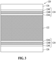
- FIG. 3 is a diagram of a medium segment according to an embodiment.
- an aerosol generating system 10 may include an aerosol generating article 100 including an aerosol generating material, and an aerosol generating device 200 configured to generate an aerosol from the aerosol generating article 100.
- the aerosol generating article 100 may include a plurality of segments 110, 120, 130, and 140.
- the aerosol generating article 100 may include, from upstream to downstream, a first segment 110, a second segment 120, a third segment 130, and a fourth segment 140.
- the first segment 110 may include a filter. In an embodiment, the first segment 110 may include a cellulose acetate tow filter. The first segment 110 may have a length of about 10 millimeters (mm).
- the second segment 120 may include a medium 122.
- the medium 122 may include aerosol generating materials, fragrance materials, and/or any other material suitable for generating an aerosol.
- the medium 122 may extend between the first segment 110 and the third segment 130.
- the medium 122 may at least partially contact the first segment 110 and/or the third segment 130.
- the medium 122 may be disposed on the inner portion (e.g., the inside) of the second segment 120.
- the medium 122 may be disposed in the central portion of the second segment 120.
- the second segment 120 may have a length of about 12 mm.
- the second segment 120 may include an exothermic wrapper 124.
- the exothermic wrapper 124 may surround the medium 122 and may be disposed on the outer portion (e.g., the periphery) of the second segment 120.
- the exothermic wrapper 124 may include a first wrapper 124A contacting the medium 122 and surrounding the medium 122, a second wrapper 124C surrounding the first wrapper 124A and disposed outside the first wrapper 124A, and a heat source 124B disposed between the first wrapper 124A and the second wrapper 124C.
- the exothermic wrapper 124 may have a double-component structure that includes the first wrapper 124A contacting the medium 122 and surrounding the medium 122, and the heat source 124B disposed outside the first wrapper 124A.
- the exothermic wrapper 124 may have a double-component structure that includes the heat source 124B contacting the medium 122and surrounding the medium 122, and the second wrapper 124C disposed outside the heat source 124B.
- the heat source 124B may at least partially include a susceptor material.
- the heat source 124B may include a metal (e.g., aluminum) that may be magnetically coupled.
- first wrapper 124A and the second wrapper 124C may be formed of any material suitable for transferring heat generated by the heat source 124B.
- the first wrapper 124A and the second wrapper 124C may be at least partially formed of substantially the same material.
- the second segment 120 may include a thermal insulating wrapper 126.
- the thermal insulating wrapper 126 may surround the exothermic wrapper 124 and may be disposed on the outer portion of the second segment 120.
- the thermal insulating wrapper 126 may increase the heating efficiency of the medium 122 by substantially blocking the external flow of heat generated in the exothermic wrapper 124.
- An increase in the thermal efficiency of the medium 122 may reduce the aerosolization time, may increase the heating speed, and may reduce the heat generation of the aerosol generating device 200.
- the preheating time and/or power consumption of the aerosol generating device 200 may be reduced.
- the medium 122 may be substantially consumed, and accordingly, the aerosol generating article 100 and/or the aerosol generating device 200 may be easy to clean.
- the thermal insulating wrapper 126 protects the medium 122 together with the exothermic wrapper 124, the possibility of leakage of the aerosol generating material in the medium 122 to the aerosol generating device 200 may be reduced.
- the thermal insulating wrapper 126 may entirely surround the exothermic wrapper 124. Accordingly, heat generated in the exothermic wrapper 124 may be substantially transferred to the medium 122 within the second segment 120.
- the thermal insulating wrapper 126 may have any suitable increased basis weight sufficient to increase the insulation effect.
- the thermal insulating wrapper 126 may have a basis weight of about 40 grams per square meter (g/m 2 ) to about 80 g/m 2 .
- the thermal insulating wrapper 126 may have any suitable increased thickness sufficient to increase the insulation effect.
- the thermal insulating wrapper 126 may have a thickness of about 60 micrometers ( ⁇ m) to about 120 ⁇ m.
- the third segment 130 may include a filter.
- the third segment 130 may include a cellulose acetate filter.
- the third segment 130 may include a paper sleeve 132 configured to cool the aerosol and/or airflow.
- the paper sleeve 132 may be at least partially surrounded by a cellulose acetate tow filter.
- the paper sleeve 132 may extend between the second segment 120 and the fourth segment 140.
- the paper sleeve 132 may contact the second segment 120 and/or the fourth segment 140.
- the third segment 130 may have a length of about 12 mm.
- the fourth segment 140 may include a filter.
- the fourth segment 140 may include a cellulose acetate filter.
- the fourth segment 140 may have a length of about 14 mm.
- the aerosol generating device 200 may include a first housing 210, a second housing 220, a heater 230, and a controller 240.
- the first housing 210 may form the exterior of the aerosol generating device 200.
- the second housing 220 may be disposed within the first housing 210 and may be configured to at least partially accommodate the aerosol generating article 100.
- the heater 230 may be configured to heat the aerosol generating article 100 disposed within the second housing 220.
- the heater 230 may be configured to heat the first segment 110.
- the heater 230 may be configured to surround the second housing 220. In an embodiment, the heater 230 may be disposed in an upstream portion (e.g., the first portion) of the second housing 220 as viewed in the direction of the flow stream of air.
- the heater 230 may include a resistor.
- the heater 230 may include an electrically insulating substrate (for example, a substrate formed of polyimide), an electrically conductive track, and a heating element that generates heat as current flows through the electrically conductive track.
- the heater 230 may include a coil. At least a portion of the second housing 220 may include a susceptor material, and the heater 230 may heat the areas within the second housing 220 by being electromagnetically coupled with the susceptor material of the second housing 220.
- the controller 240 may be configured to control the operation of the heater 230.
- the controller 240 may control the temperature of the heater 230.
- the controller 240 may determine the operation start time of the heater 230.
- the controller 240 may determine the operation end point of the heater 230.
- the controller 240 may be configured to control the operation of the heater 230 based on a received signal (e.g., a signal of a sensor).
- the controller 240 may be implemented by a processor.
- the controller 240 may be implemented as an array of a plurality of logic gates, or may be implemented as a combination of a microprocessor and a memory in which a program executable by the microprocessor is stored.
- the aerosol generating device 200 may include a sensor configured to detect various characteristics of the aerosol generating article 100.
- the sensor may be configured to detect whether the aerosol generating article 100 is disposed in a predetermined position within the second housing 220.
- the sensor may be configured to detect the amount of aerosol generating material (e.g., nicotine) within the aerosol generating article 100.
- the sensor may include a puff sensor configured to detect the number of puffs of the user.
- the sensor may include at least one temperature sensor configured to detect the temperature of the heater 230.
- the sensor may include at least one temperature sensor configured to detect the temperature of the first segment 110, the temperature of the second segment 120, the temperature of the third segment 130, and/or the temperature of the fourth segment 140.
Landscapes
- Physics & Mathematics (AREA)
- Electromagnetism (AREA)
- Cosmetics (AREA)
- Cigarettes, Filters, And Manufacturing Of Filters (AREA)
- Medicinal Preparation (AREA)
- Thermotherapy And Cooling Therapy Devices (AREA)
Abstract
Description
- The following description relates to a medium segment, an aerosol generating article, and a system including the aerosol generating article.
- Aerosol generating devices that generate an aerosol in a non-burning manner from an aerosol generating article (e.g., a cigarette) are being developed. For example,
Korean Patent Publication No. 10-2019-0119465 - One aspect of the present disclosure may provide a medium segment that may increase the heating efficiency of the medium, an aerosol generating article, and a system including the aerosol generating article.
- According to an embodiment, a medium segment for an aerosol generating article includes a medium, an exothermic wrapper including a heat source and surrounding the medium, and a thermal insulating wrapper surrounding the exothermic wrapper.
- According to an embodiment, the thermal insulating wrapper may have a basis weight of about 40 grams per square meter (g/m2) to about 80 g/m2.
- According to an embodiment, the thermal insulating wrapper may have a thickness of about 60 micrometers (µm) to about 120 µm.
- According to an embodiment, the exothermic wrapper may further include a first wrapper surrounding the medium, and a second wrapper surrounding the first wrapper, wherein the heat source may be disposed between the first wrapper and the second wrapper.
- According to an embodiment, the exothermic wrapper may further include a wrapper surrounding the medium, and the heat source may be disposed between the medium and the wrapper or outside the wrapper.
- According to an embodiment, the heat source may include a susceptor material.
- According to an embodiment, an aerosol generating article includes a first segment including a filter, and a second segment disposed downstream of the first segment, wherein the second segment may include a medium segment, wherein the medium segment may include a medium, an exothermic wrapper including a heat source and surrounding the medium, and a thermal insulating wrapper surrounding the exothermic wrapper.
- According to an embodiment, the aerosol generating article may further include a third segment disposed downstream of the second segment and configured to cool an aerosol.
- According to an embodiment, the aerosol generating article may further include a fourth segment disposed downstream of the third segment and including a filter.
- According to an embodiment, an aerosol generating system includes an aerosol generating article including a first segment including a filter and a second segment disposed downstream of the first segment, wherein the second segment may include a medium segment, wherein the medium segment may include a medium, an exothermic wrapper including a heat source and surrounding the medium, and a thermal insulating wrapper surrounding the exothermic wrapper, and an aerosol generating device including a first housing, a second housing disposed within the first housing and configured to accommodate the aerosol generating article, and a heater disposed around the second housing and configured to heat the second segment.
- According to an embodiment, the heating efficiency of a medium may be increased. According to an embodiment, the heating speed of the medium may be increased and the preheating time of the medium may be decreased. According to an embodiment, the power consumption of an aerosol generating device for heating the medium may be reduced and the heat generation of the device may be decreased. According to an embodiment, the aerosol generating device may be easy to clean. According to an embodiment, the possibility of leakage of the material including the medium to the outside may be reduced. The effects of a medium segment, an aerosol generating article, and a system including the same according to an embodiment are not limited to the above-mentioned effects, and other unmentioned effects can be clearly understood from the following description by one of ordinary skill in the art.
- The foregoing and other aspects, features, and advantages of certain embodiments of the disclosure will become apparent from the following detailed description with reference to the accompanying drawings.
-
FIG. 1 is a diagram of an aerosol generating system according to an embodiment. -
FIG. 2 is a diagram of an aerosol generating article according to an embodiment. -
FIG. 3 is a diagram of a medium segment according to an embodiment. - Hereinafter, embodiments will be described in detail with reference to the accompanying drawings. However, various alterations and modifications may be made to the embodiments. Here, the embodiments are not construed as limited to the disclosure. The embodiments should be understood to include all changes, equivalents, and replacements within the idea and the technical scope of the disclosure.
- The terminology used herein is for the purpose of describing particular embodiments only and is not to be limiting of the embodiments. The singular forms "a", "an", and "the" are intended to include the plural forms as well, unless the context clearly indicates otherwise. It will be further understood that the terms "comprises/comprising" and/or "includes/including" when used herein, specify the presence of stated features, integers, steps, operations, elements, and/or components, but do not preclude the presence or addition of one or more other features, integers, steps, operations, elements, components and/or groups thereof.
- Unless otherwise defined, all terms including technical and scientific terms used herein have the same meaning as commonly understood by one of ordinary skill in the art to which embodiments belong. Terms defined in dictionaries generally used should be construed to have meanings matching with contextual meanings in the related art and are not to be construed as an ideal or excessively formal meaning unless otherwise defined herein.
- When describing the embodiments with reference to the accompanying drawings, like reference numerals refer to like components and a repeated description related thereto will be omitted. In the description of embodiments, detailed description of well-known related structures or functions will be omitted when it is deemed that such description will cause ambiguous interpretation of the present disclosure.
- In addition, terms such as first, second, A, B, (a), (b), and the like may be used to describe components of the embodiments. Each of these terms is not used to define an essence, order or sequence of a corresponding component but used merely to distinguish the corresponding component from other component(s). It should be noted that if one component is described as being "connected", "coupled" or "joined" to another component, the former may be directly "connected," "coupled", and "joined" to the latter or "connected", "coupled", and "joined" to the latter via another component.
- The same name may be used to describe an element included in the embodiments described above and an element having a common function. Unless disclosed to the contrary, the descriptions of any one embodiment may be applied to other embodiments and thus, duplicated descriptions will be omitted.
- The term "aerosol generating material" used herein refers to a material from which an aerosol may be generated. The aerosol may include a volatile compound. The aerosol generating material may be solid or liquid. For example, a solid aerosol generating material may include a solid material that is based on tobacco raw materials, such as reconstituted tobacco sheets, cut tobacco leaves, reconstituted tobacco, and the like, and a liquid aerosol generating material may include a liquid composition that is based on nicotine, tobacco extracts, and/or various flavoring agents. The aerosol generating material may include an aerosol former to stably form visible smoke and/or an aerosol.
- The term "aerosol generating device" used herein refers to a device that generates an aerosol using an aerosol generating article such that the aerosol may be inhaled through the mouth of a user directly to the lungs of the user.
- The term "upstream" or "upstream direction" used herein refers to a direction away from the mouth of a user and the term "downstream" or "downstream direction" refers to a direction toward the mouth of a user. The terms "upstream" and "downstream" may be used to describe relative positions of components of an aerosol generating article.
- The term "puff" used herein refers to inhalation by a user. Inhalation refers to drawing in through the mouth or nose of a user into the oral cavity, nasal cavity, or lungs of the user.
- The "longitudinal direction" used herein refers to a direction corresponding to the longitudinal axis of an aerosol generating article.
-
FIG. 1 is a diagram of an aerosol generating system according to an embodiment.FIG. 2 is a diagram of an aerosol generating article according to an embodiment.FIG. 3 is a diagram of a medium segment according to an embodiment. - Referring to
FIGS. 1 to 3 , anaerosol generating system 10 may include an aerosol generatingarticle 100 including an aerosol generating material, and anaerosol generating device 200 configured to generate an aerosol from theaerosol generating article 100. - In an embodiment, the
aerosol generating article 100 may include a plurality ofsegments aerosol generating article 100 may include, from upstream to downstream, afirst segment 110, asecond segment 120, athird segment 130, and afourth segment 140. - In an embodiment, the
first segment 110 may include a filter. In an embodiment, thefirst segment 110 may include a cellulose acetate tow filter. Thefirst segment 110 may have a length of about 10 millimeters (mm). - In an embodiment, the
second segment 120 may include a medium 122. The medium 122 may include aerosol generating materials, fragrance materials, and/or any other material suitable for generating an aerosol. The medium 122 may extend between thefirst segment 110 and thethird segment 130. The medium 122 may at least partially contact thefirst segment 110 and/or thethird segment 130. The medium 122 may be disposed on the inner portion (e.g., the inside) of thesecond segment 120. The medium 122 may be disposed in the central portion of thesecond segment 120. Thesecond segment 120 may have a length of about 12 mm. - In an embodiment, the
second segment 120 may include anexothermic wrapper 124. Theexothermic wrapper 124 may surround the medium 122 and may be disposed on the outer portion (e.g., the periphery) of thesecond segment 120. Theexothermic wrapper 124 may include afirst wrapper 124A contacting the medium 122 and surrounding the medium 122, asecond wrapper 124C surrounding thefirst wrapper 124A and disposed outside thefirst wrapper 124A, and aheat source 124B disposed between thefirst wrapper 124A and thesecond wrapper 124C. - In an embodiment, the
exothermic wrapper 124 may have a double-component structure that includes thefirst wrapper 124A contacting the medium 122 and surrounding the medium 122, and theheat source 124B disposed outside thefirst wrapper 124A. - In an embodiment, the
exothermic wrapper 124 may have a double-component structure that includes theheat source 124B contacting the medium 122and surrounding the medium 122, and thesecond wrapper 124C disposed outside theheat source 124B. - In an embodiment, the
heat source 124B may at least partially include a susceptor material. For example, theheat source 124B may include a metal (e.g., aluminum) that may be magnetically coupled. - In an embodiment, the
first wrapper 124A and thesecond wrapper 124C may be formed of any material suitable for transferring heat generated by theheat source 124B. Thefirst wrapper 124A and thesecond wrapper 124C may be at least partially formed of substantially the same material. - In an embodiment, the
second segment 120 may include a thermal insulatingwrapper 126. The thermal insulatingwrapper 126 may surround theexothermic wrapper 124 and may be disposed on the outer portion of thesecond segment 120. The thermal insulatingwrapper 126 may increase the heating efficiency of the medium 122 by substantially blocking the external flow of heat generated in theexothermic wrapper 124. An increase in the thermal efficiency of the medium 122 may reduce the aerosolization time, may increase the heating speed, and may reduce the heat generation of theaerosol generating device 200. In addition, the preheating time and/or power consumption of theaerosol generating device 200 may be reduced. In addition, the medium 122 may be substantially consumed, and accordingly, theaerosol generating article 100 and/or theaerosol generating device 200 may be easy to clean. In addition, since the thermal insulatingwrapper 126 protects the medium 122 together with theexothermic wrapper 124, the possibility of leakage of the aerosol generating material in the medium 122 to theaerosol generating device 200 may be reduced. - In an embodiment, the thermal insulating
wrapper 126 may entirely surround theexothermic wrapper 124. Accordingly, heat generated in theexothermic wrapper 124 may be substantially transferred to the medium 122 within thesecond segment 120. - In an embodiment, the thermal insulating
wrapper 126 may have any suitable increased basis weight sufficient to increase the insulation effect. For example, the thermal insulatingwrapper 126 may have a basis weight of about 40 grams per square meter (g/m2) to about 80 g/m2. - In an embodiment, the thermal insulating
wrapper 126 may have any suitable increased thickness sufficient to increase the insulation effect. For example, the thermal insulatingwrapper 126 may have a thickness of about 60 micrometers (µm) to about 120 µm. - In an embodiment, the
third segment 130 may include a filter. For example, thethird segment 130 may include a cellulose acetate filter. In an embodiment, thethird segment 130 may include a paper sleeve 132 configured to cool the aerosol and/or airflow. The paper sleeve 132 may be at least partially surrounded by a cellulose acetate tow filter. The paper sleeve 132 may extend between thesecond segment 120 and thefourth segment 140. The paper sleeve 132 may contact thesecond segment 120 and/or thefourth segment 140. Thethird segment 130 may have a length of about 12 mm. - In an embodiment, the
fourth segment 140 may include a filter. For example, thefourth segment 140 may include a cellulose acetate filter. Thefourth segment 140 may have a length of about 14 mm. - In an embodiment, the
aerosol generating device 200 may include afirst housing 210, asecond housing 220, aheater 230, and acontroller 240. - In an embodiment, the
first housing 210 may form the exterior of theaerosol generating device 200. Thesecond housing 220 may be disposed within thefirst housing 210 and may be configured to at least partially accommodate theaerosol generating article 100. - In an embodiment, the
heater 230 may be configured to heat theaerosol generating article 100 disposed within thesecond housing 220. For example, theheater 230 may be configured to heat thefirst segment 110. - In an embodiment, the
heater 230 may be configured to surround thesecond housing 220. In an embodiment, theheater 230 may be disposed in an upstream portion (e.g., the first portion) of thesecond housing 220 as viewed in the direction of the flow stream of air. - In an embodiment, the
heater 230 may include a resistor. For example, theheater 230 may include an electrically insulating substrate (for example, a substrate formed of polyimide), an electrically conductive track, and a heating element that generates heat as current flows through the electrically conductive track. - In an embodiment, the
heater 230 may include a coil. At least a portion of thesecond housing 220 may include a susceptor material, and theheater 230 may heat the areas within thesecond housing 220 by being electromagnetically coupled with the susceptor material of thesecond housing 220. - In an embodiment, the
controller 240 may be configured to control the operation of theheater 230. Thecontroller 240 may control the temperature of theheater 230. Thecontroller 240 may determine the operation start time of theheater 230. Thecontroller 240 may determine the operation end point of theheater 230. Thecontroller 240 may be configured to control the operation of theheater 230 based on a received signal (e.g., a signal of a sensor). - In an embodiment, the
controller 240 may be implemented by a processor. Thecontroller 240 may be implemented as an array of a plurality of logic gates, or may be implemented as a combination of a microprocessor and a memory in which a program executable by the microprocessor is stored. - In an embodiment not shown, the
aerosol generating device 200 may include a sensor configured to detect various characteristics of theaerosol generating article 100. The sensor may be configured to detect whether theaerosol generating article 100 is disposed in a predetermined position within thesecond housing 220. The sensor may be configured to detect the amount of aerosol generating material (e.g., nicotine) within theaerosol generating article 100. The sensor may include a puff sensor configured to detect the number of puffs of the user. The sensor may include at least one temperature sensor configured to detect the temperature of theheater 230. The sensor may include at least one temperature sensor configured to detect the temperature of thefirst segment 110, the temperature of thesecond segment 120, the temperature of thethird segment 130, and/or the temperature of thefourth segment 140. - While this disclosure includes specific embodiment, it will be apparent to one of ordinary skill in the art that various changes in form and details may be made in these embodiments without departing from the scope of the claims and their equivalents. The embodiments described herein are to be considered in a descriptive sense only, and not for purposes of limitation. Descriptions of features or aspects in each embodiment are to be considered as being applicable to similar features or aspects in other embodiments. For example, suitable results may be achieved if the described techniques are performed in a different order, and/or if components in a described system, architecture, device, or circuit are combined in a different manner, or replaced or supplemented by other components or their equivalents.
- Therefore, other implementations, other embodiments, and/or equivalents of the claims are within the scope of the following claims.
Claims (10)
- A medium segment for an aerosol generating article, the medium segment comprising:a medium;an exothermic wrapper comprising a heat source and surrounding the medium; anda thermal insulating wrapper surrounding the exothermic wrapper.
- The medium segment of claim 1, wherein the thermal insulating wrapper has a basis weight of about 40 grams per square meter (g/m2) to about 80 g/m2.
- The medium segment of claim 1, wherein the thermal insulating wrapper has a thickness of about 60 micrometers (µm) to about 120 µm.
- The medium segment of claim 1, wherein the exothermic wrapper further comprises:a first wrapper surrounding the medium; anda second wrapper surrounding the first wrapper,wherein the heat source is disposed between the first wrapper and the second wrapper.
- The medium segment of claim 1, wherein the exothermic wrapper further comprises a wrapper surrounding the medium, and the heat source is disposed between the medium and the wrapper or outside the wrapper.
- The medium segment of claim 1, wherein the heat source comprises a susceptor material.
- An aerosol generating article comprising: a first segment comprising a filter, and a second segment disposed downstream of the first segment,
wherein the second segment comprises a medium segment, wherein the medium segment comprises:a medium;an exothermic wrapper comprising a heat source and surrounding the medium; anda thermal insulating wrapper surrounding the exothermic wrapper. - The aerosol generating article of claim 7, further comprising a third segment disposed downstream of the second segment and configured to cool an aerosol.
- The aerosol generating article of claim 8, further comprising a fourth segment disposed downstream of the third segment and comprising a filter.
- An aerosol generating system comprising:an aerosol generating article comprising a first segment comprising a filter and a second segment disposed downstream of the first segment, wherein the second segment comprises a medium segment, wherein the medium segment comprises a medium, an exothermic wrapper comprising a heat source and surrounding the medium, and a thermal insulating wrapper surrounding the exothermic wrapper; andan aerosol generating device comprising a first housing, a second housing disposed within the first housing and configured to accommodate the aerosol generating article, and a heater disposed around the second housing and configured to heat the second segment.
Applications Claiming Priority (2)
| Application Number | Priority Date | Filing Date | Title |
|---|---|---|---|
| KR1020210190969A KR20230101132A (en) | 2021-12-29 | 2021-12-29 | Medium segment, aerosol forming article and system comprising the same |
| PCT/KR2022/016516 WO2023128195A1 (en) | 2021-12-29 | 2022-10-27 | Medium segment, aerosol-generating article, and system comprising same |
Publications (2)
| Publication Number | Publication Date |
|---|---|
| EP4324342A1 true EP4324342A1 (en) | 2024-02-21 |
| EP4324342A4 EP4324342A4 (en) | 2024-10-30 |
Family
ID=86999341
Family Applications (1)
| Application Number | Title | Priority Date | Filing Date |
|---|---|---|---|
| EP22916349.8A Pending EP4324342A4 (en) | 2021-12-29 | 2022-10-27 | MEDIA SEGMENT, AEROSOL GENERATING ARTICLES AND SYSTEM |
Country Status (6)
| Country | Link |
|---|---|
| US (1) | US20240365848A1 (en) |
| EP (1) | EP4324342A4 (en) |
| JP (1) | JP7670263B2 (en) |
| KR (1) | KR20230101132A (en) |
| CN (1) | CN117295413A (en) |
| WO (1) | WO2023128195A1 (en) |
Family Cites Families (24)
| Publication number | Priority date | Publication date | Assignee | Title |
|---|---|---|---|---|
| US5981011A (en) * | 1992-01-22 | 1999-11-09 | A*Ware Technologies, L.C. | Coated sheet material |
| JP6966995B2 (en) * | 2015-09-11 | 2021-11-17 | フィリップ・モーリス・プロダクツ・ソシエテ・アノニム | Multi-segment components for aerosol-generating articles |
| US20170119048A1 (en) * | 2015-10-30 | 2017-05-04 | British American Tobacco (Investments) Limited | Article for Use with Apparatus for Heating Smokable Material |
| GB2562764A (en) * | 2017-05-24 | 2018-11-28 | Robert Hopps Jason | Tobacco-containing consumable for aerosol generating devices |
| KR102551450B1 (en) * | 2017-08-09 | 2023-07-06 | 필립모리스 프로덕츠 에스.에이. | Aerosol generating device with susceptor layer |
| CN207574504U (en) * | 2017-11-28 | 2018-07-06 | 上海新型烟草制品研究院有限公司 | The cigarette paper of cigarette of not burning for self-heating and self-heating are not burnt cigarette |
| KR102697915B1 (en) * | 2017-12-29 | 2024-08-26 | 제이티 인터내셔널 소시에떼 아노님 | Aerosol-generating articles and methods for producing same |
| KR102369446B1 (en) | 2018-04-12 | 2022-03-02 | 주식회사 케이티앤지 | Aerosol-generating device |
| TWI802697B (en) * | 2018-05-18 | 2023-05-21 | 瑞士商Jt國際公司 | Aerosol generating article, aerosol generating device, aerosol generating system and method of inductively heating and manufacturing an aerosol generating article |
| JP7358397B2 (en) * | 2018-05-21 | 2023-10-10 | ジェイティー インターナショナル エスエイ | Aerosol-generating article, method for manufacturing aerosol-generating article, and aerosol-generating system |
| JP7344228B2 (en) * | 2018-06-27 | 2023-09-13 | フィリップ・モーリス・プロダクツ・ソシエテ・アノニム | Aerosol-generating articles and apparatus for forming aerosol-generating articles |
| KR102330290B1 (en) * | 2018-09-12 | 2021-11-24 | 주식회사 케이티앤지 | A wrapper comprising thermal insulating element |
| GB201816649D0 (en) * | 2018-10-12 | 2018-11-28 | Nicoventures Trading Ltd | Article for use with apparatus for heating aerosolisable material |
| CN113038847B (en) * | 2018-11-14 | 2025-03-14 | 日本烟草产业株式会社 | Non-combustion heat-to-smoking articles and non-combustion heat-to-smoking systems |
| MY198243A (en) * | 2018-12-06 | 2023-08-16 | Philip Morris Products Sa | Aerosol-Generating Article With Laminated Wrapper |
| US11937645B2 (en) * | 2018-12-17 | 2024-03-26 | Philip Morris Products S.A. | Aerosol generating article for use with an aerosol generating device |
| EP3852555B1 (en) * | 2018-12-17 | 2025-02-05 | Philip Morris Products S.A. | Aerosol generating article comprising a heat source |
| CN109805455A (en) * | 2019-03-21 | 2019-05-28 | 云南中烟工业有限责任公司 | It is a kind of to heat the cigarette Smoke-generating System that do not burn |
| KR102341841B1 (en) * | 2019-08-08 | 2021-12-21 | 주식회사 케이티앤지 | Aerosol generating article comprising thermally conductive wrapper |
| KR102275791B1 (en) * | 2019-08-16 | 2021-07-09 | 주식회사 케이티앤지 | Aerosol generating article, device and system |
| WO2021053029A1 (en) * | 2019-09-19 | 2021-03-25 | Philip Morris Products S.A. | Hollow aerosol-generating article with tubular substrate layers |
| KR102330306B1 (en) * | 2019-10-11 | 2021-11-24 | 주식회사 케이티앤지 | Aerosol generating article, device and system |
| KR102640828B1 (en) * | 2020-10-23 | 2024-02-23 | 주식회사 케이티앤지 | Induction heating type aerosol-generating article and apparatus |
| CN113699830B (en) * | 2021-09-30 | 2023-10-24 | 湖北中烟工业有限责任公司 | Multi-layer cigarette paper for electromagnetic induction |
-
2021
- 2021-12-29 KR KR1020210190969A patent/KR20230101132A/en active Pending
-
2022
- 2022-10-27 JP JP2023566894A patent/JP7670263B2/en active Active
- 2022-10-27 CN CN202280035087.9A patent/CN117295413A/en active Pending
- 2022-10-27 EP EP22916349.8A patent/EP4324342A4/en active Pending
- 2022-10-27 US US18/289,440 patent/US20240365848A1/en active Pending
- 2022-10-27 WO PCT/KR2022/016516 patent/WO2023128195A1/en not_active Ceased
Also Published As
| Publication number | Publication date |
|---|---|
| WO2023128195A1 (en) | 2023-07-06 |
| JP7670263B2 (en) | 2025-04-30 |
| EP4324342A4 (en) | 2024-10-30 |
| KR20230101132A (en) | 2023-07-06 |
| CN117295413A (en) | 2023-12-26 |
| US20240365848A1 (en) | 2024-11-07 |
| JP2024517195A (en) | 2024-04-19 |
Similar Documents
| Publication | Publication Date | Title |
|---|---|---|
| JP7078317B2 (en) | Aerosol generators for cigarettes and cigarettes | |
| CN112822953B (en) | Aerosol-generating articles, aerosol-generating devices, and aerosol-generating systems | |
| CN113645866B (en) | Aerosol generation systems and cigarettes | |
| US20190142066A1 (en) | Aerosol Generating Systems | |
| CN114599243B (en) | Aerosol generating system, method of controlling the same, and computer-readable recording medium | |
| US20230095659A1 (en) | Aerosol generating device and method of control of the same | |
| EP3892124B1 (en) | Cartridge and aerosol-generating apparatus comprising same | |
| JP7633421B2 (en) | Aerosol Generator | |
| JP7517631B2 (en) | Aerosol generating device with differential heating function and aerosol generating article applied thereto | |
| JP7532732B2 (en) | Aerosol generating device with differential heating function and aerosol generating article applied thereto | |
| CN112135535A (en) | Aerosol-generating articles, aerosol-generating systems, and methods for generating flavored aerosols | |
| US20240365848A1 (en) | Medium segment, aerosol-generating article, and system comprising same | |
| KR20220078284A (en) | Aerosol generating device | |
| KR102860483B1 (en) | Aerosol forming article and system comprising the same | |
| EP4316276A1 (en) | Filter segment, aerosol-generating article, and system comprising same | |
| US20240268451A1 (en) | Aerosol-generating device and medium receiving rod | |
| KR102965025B1 (en) | Filter segment, aerosol forming article and system comprising the same | |
| KR102737189B1 (en) | Aerosol generating device and system comprising the same | |
| EP4599703A1 (en) | Aerosol-generating product, and aerosol-generating system containing same | |
| EP4331405A1 (en) | Aerosol generation device for reducing smell of mainstream smoke | |
| KR20230100466A (en) | Aerosol generating system | |
| KR20230097373A (en) | Aerosol generating device and system comprising the same | |
| US20250089754A1 (en) | Aerosol generating article and method of manufacturing the same | |
| WO2024243722A1 (en) | Heating system | |
| KR20240047890A (en) | Aerosol Generating Article and Aerosol Generating System including the same |
Legal Events
| Date | Code | Title | Description |
|---|---|---|---|
| STAA | Information on the status of an ep patent application or granted ep patent |
Free format text: STATUS: THE INTERNATIONAL PUBLICATION HAS BEEN MADE |
|
| PUAI | Public reference made under article 153(3) epc to a published international application that has entered the european phase |
Free format text: ORIGINAL CODE: 0009012 |
|
| STAA | Information on the status of an ep patent application or granted ep patent |
Free format text: STATUS: REQUEST FOR EXAMINATION WAS MADE |
|
| 17P | Request for examination filed |
Effective date: 20231115 |
|
| AK | Designated contracting states |
Kind code of ref document: A1 Designated state(s): AL AT BE BG CH CY CZ DE DK EE ES FI FR GB GR HR HU IE IS IT LI LT LU LV MC ME MK MT NL NO PL PT RO RS SE SI SK SM TR |
|
| A4 | Supplementary search report drawn up and despatched |
Effective date: 20240926 |
|
| RIC1 | Information provided on ipc code assigned before grant |
Ipc: H05B 6/06 20060101ALI20240920BHEP Ipc: A24F 40/20 20200101ALI20240920BHEP Ipc: A24D 1/20 20200101ALI20240920BHEP Ipc: A24F 40/465 20200101ALI20240920BHEP Ipc: A24D 1/04 20060101ALI20240920BHEP Ipc: A24D 3/02 20060101ALI20240920BHEP Ipc: H05B 6/10 20060101ALI20240920BHEP Ipc: A24D 1/22 20200101ALI20240920BHEP Ipc: A24D 1/02 20060101AFI20240920BHEP |
|
| DAV | Request for validation of the european patent (deleted) | ||
| DAX | Request for extension of the european patent (deleted) | ||
| STAA | Information on the status of an ep patent application or granted ep patent |
Free format text: STATUS: EXAMINATION IS IN PROGRESS |