EP4323849B1 - Method for controlling an air-cooled refrigeration cycle apparatus - Google Patents
Method for controlling an air-cooled refrigeration cycle apparatus Download PDFInfo
- Publication number
- EP4323849B1 EP4323849B1 EP22717278.0A EP22717278A EP4323849B1 EP 4323849 B1 EP4323849 B1 EP 4323849B1 EP 22717278 A EP22717278 A EP 22717278A EP 4323849 B1 EP4323849 B1 EP 4323849B1
- Authority
- EP
- European Patent Office
- Prior art keywords
- threshold value
- superheat
- tdi
- shei
- equal
- Prior art date
- Legal status (The legal status is an assumption and is not a legal conclusion. Google has not performed a legal analysis and makes no representation as to the accuracy of the status listed.)
- Active
Links
Images


Classifications
-
- G—PHYSICS
- G05—CONTROLLING; REGULATING
- G05D—SYSTEMS FOR CONTROLLING OR REGULATING NON-ELECTRIC VARIABLES
- G05D23/00—Control of temperature
- G05D23/19—Control of temperature characterised by the use of electric means
- G05D23/1927—Control of temperature characterised by the use of electric means using a plurality of sensors
- G05D23/193—Control of temperature characterised by the use of electric means using a plurality of sensors sensing the temperaure in different places in thermal relationship with one or more spaces
- G05D23/1932—Control of temperature characterised by the use of electric means using a plurality of sensors sensing the temperaure in different places in thermal relationship with one or more spaces to control the temperature of a plurality of spaces
- G05D23/1934—Control of temperature characterised by the use of electric means using a plurality of sensors sensing the temperaure in different places in thermal relationship with one or more spaces to control the temperature of a plurality of spaces each space being provided with one sensor acting on one or more control means
-
- F—MECHANICAL ENGINEERING; LIGHTING; HEATING; WEAPONS; BLASTING
- F25—REFRIGERATION OR COOLING; COMBINED HEATING AND REFRIGERATION SYSTEMS; HEAT PUMP SYSTEMS; MANUFACTURE OR STORAGE OF ICE; LIQUEFACTION SOLIDIFICATION OF GASES
- F25B—REFRIGERATION MACHINES, PLANTS OR SYSTEMS; COMBINED HEATING AND REFRIGERATION SYSTEMS; HEAT PUMP SYSTEMS
- F25B49/00—Arrangement or mounting of control or safety devices
- F25B49/02—Arrangement or mounting of control or safety devices for compression type machines, plants or systems
-
- F—MECHANICAL ENGINEERING; LIGHTING; HEATING; WEAPONS; BLASTING
- F25—REFRIGERATION OR COOLING; COMBINED HEATING AND REFRIGERATION SYSTEMS; HEAT PUMP SYSTEMS; MANUFACTURE OR STORAGE OF ICE; LIQUEFACTION SOLIDIFICATION OF GASES
- F25B—REFRIGERATION MACHINES, PLANTS OR SYSTEMS; COMBINED HEATING AND REFRIGERATION SYSTEMS; HEAT PUMP SYSTEMS
- F25B5/00—Compression machines, plants or systems, with several evaporator circuits, e.g. for varying refrigerating capacity
- F25B5/02—Compression machines, plants or systems, with several evaporator circuits, e.g. for varying refrigerating capacity arranged in parallel
-
- F—MECHANICAL ENGINEERING; LIGHTING; HEATING; WEAPONS; BLASTING
- F25—REFRIGERATION OR COOLING; COMBINED HEATING AND REFRIGERATION SYSTEMS; HEAT PUMP SYSTEMS; MANUFACTURE OR STORAGE OF ICE; LIQUEFACTION SOLIDIFICATION OF GASES
- F25B—REFRIGERATION MACHINES, PLANTS OR SYSTEMS; COMBINED HEATING AND REFRIGERATION SYSTEMS; HEAT PUMP SYSTEMS
- F25B2600/00—Control issues
- F25B2600/25—Control of valves
- F25B2600/2513—Expansion valves
-
- F—MECHANICAL ENGINEERING; LIGHTING; HEATING; WEAPONS; BLASTING
- F25—REFRIGERATION OR COOLING; COMBINED HEATING AND REFRIGERATION SYSTEMS; HEAT PUMP SYSTEMS; MANUFACTURE OR STORAGE OF ICE; LIQUEFACTION SOLIDIFICATION OF GASES
- F25B—REFRIGERATION MACHINES, PLANTS OR SYSTEMS; COMBINED HEATING AND REFRIGERATION SYSTEMS; HEAT PUMP SYSTEMS
- F25B2700/00—Sensing or detecting of parameters; Sensors therefor
- F25B2700/21—Temperatures
- F25B2700/2104—Temperatures of an indoor room or compartment
-
- F—MECHANICAL ENGINEERING; LIGHTING; HEATING; WEAPONS; BLASTING
- F25—REFRIGERATION OR COOLING; COMBINED HEATING AND REFRIGERATION SYSTEMS; HEAT PUMP SYSTEMS; MANUFACTURE OR STORAGE OF ICE; LIQUEFACTION SOLIDIFICATION OF GASES
- F25B—REFRIGERATION MACHINES, PLANTS OR SYSTEMS; COMBINED HEATING AND REFRIGERATION SYSTEMS; HEAT PUMP SYSTEMS
- F25B2700/00—Sensing or detecting of parameters; Sensors therefor
- F25B2700/21—Temperatures
- F25B2700/2117—Temperatures of an evaporator
- F25B2700/21171—Temperatures of an evaporator of the fluid cooled by the evaporator
Definitions
- the present invention concerns a method for controlling an air-cooled refrigeration cycle apparatus, the air-cooled refrigeration cycle apparatus and a related computer program product, in particular for controlling, independently between one another and according to a control curve, a plurality of indoor units of the air-cooled refrigeration cycle apparatus.
- Air-cooled refrigeration cycle apparatuses are widely known and used for managing media temperature and/or humidity in closed spaces.
- variable refrigerant flow (VRF) systems are used for the heating, ventilation, and air conditioning (HVAC) applications.
- HVAC heating, ventilation, and air conditioning
- HVAC applications may require that several closed spaces are heated or ventilated by the same VRF system at respective temperatures different between them, and this cannot be achieved in known VRF system where all the indoor units are connected to the same refrigerant piping and condensing unit/s. Such condition is typical in ICT cooling application wherein the VRF system is used for conditioning sever machines of an ICT system.
- Document US 2011/023534 A1 relates to refrigeration systems including refrigerant circuits performing refrigeration cycles, and more particularly to techniques for controlling operation of a refrigeration system including a refrigerant circuit in which a plurality of evaporators are connected to each other.
- Document US 2016/334142 relates generally to transport refrigeration systems, and more particularly to adaptive control of a multi-compartment transport refrigeration system.
- Document US 2019/078818 relates generally to a refrigeration system and more particularly to a refrigeration system with a subcooler configured to subcool a liquid refrigerant.
- Document US 2015/059373 pertains to the field of refrigerant vapor compression systems, and particularly to a system for dynamically optimizing capacity and efficiency during less than optimal operating conditions to provide enhanced performance.
- An aim of the present invention is to satisfy the above mentioned needs.
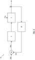
- FIG 1 schematically shows an air-cooled refrigeration cycle apparatus 1 for heating, ventilation, and air conditioning (HVAC) applications.
- the air-cooled refrigeration cycle apparatus 1 is configured to refrigerate the air in at least one closed space (i.e., rooms 11, 13 shown in Figure 2 ).
- the air-cooled refrigeration cycle apparatus 1 comprises a compressor mean 2 configured to move a refrigerant fluid between an inlet 2a and an outlet 2b of the compressor mean 2 and to increase its pressure.
- the air-cooled refrigeration cycle apparatus 1 further comprises an air-cooled module 3 fluidly connected in series to the compressor mean 2 and configured to desuperheat, condense and subcool the refrigerant fluid between an inlet 3a and an outlet 3b of the air-cooled module 3, thereby exchanging thermal energy with the ambient air and, in particular, providing heat to the latter.
- an air-cooled module 3 fluidly connected in series to the compressor mean 2 and configured to desuperheat, condense and subcool the refrigerant fluid between an inlet 3a and an outlet 3b of the air-cooled module 3, thereby exchanging thermal energy with the ambient air and, in particular, providing heat to the latter.
- the compressor mean 2 and the air-cooled module 3 are comprised in an outdoor unit 7 of the air-cooled refrigeration cycle apparatus 1, placed outside the one or more closed spaces.
- the air-cooled refrigeration cycle apparatus 1 further comprises a plurality of indoor units 9 ( Figure 1 exemplarily shows three indoor units 9), placed inside the one or more closed spaces.
- Each indoor unit 9 comprises a respective expansion mean 4 that is fluidly connected in series to the air-cooled module 3 and is configured to decrease the pressure of the refrigerant fluid between a respective inlet 4a and a respective outlet 4b of said expansion mean 4.
- the expansion means 4 are electronic expansion valves (EEV), as better described in the following.
- Each indoor unit 9 further comprises a respective evaporation mean (or evaporator) 5 that is fluidly connected in series to the expansion mean 4 and is configured to allow the passage of phase from liquid to gaseous state of said refrigerant fluid between an inlet 5a and an outlet 5b of said evaporation mean 5.
- the evaporation mean 5 is configured to evaporate and superheat the temperature of the refrigerant fluid, thereby exchanging thermal energy with the media (e.g., air) in the closed space housing the indoor unit 9, and in particular absorbing heat from the media.
- the inlet 2a of the compressor mean 2 is further fluidly connected in series to each evaporation mean 5.
- the indoor units 9 are connected in parallel between them, and each of them is connected in series between the outlet 3b of the air-cooled module 3 and the inlet 2a of the compressor mean 2.
- the air-cooled refrigeration cycle arrangement 1 comprises a plurality of temperature sensors 15 and a control unit 17 (e.g., an FPGA or a dedicated controller), shown in Figure 2 .
- a control unit 17 e.g., an FPGA or a dedicated controller
- Each temperature sensor 15 is coupled to a respective evaporation mean 5 so as to detect the temperature of the media at the evaporation mean 5 (in the following, also called delivery air temperature TDi), thus detecting the thermal energy exchange caused in the media by said respective evaporation mean 5.
- the temperature sensors 15 generate respective temperature signals indicative of the temperatures of the respective evaporation means 5.
- each temperature sensor 15 is closer to the respective evaporation mean 5 than to any other evaporation mean 5.
- each temperature sensor 15 is comprised in the indoor unit 9 of the respective evaporation mean 5.
- the control unit 17 is coupled (e.g., electrically or via transceiving modules) to the temperature sensors 15, the compressor mean 2 and the expansion means 4, and is configured to acquire the temperature signals from the temperature sensors 15 and to control the compressor mean 2 and the expansion means 4 based on the acquired temperature signals, as better described in the following.
- the control unit 17 is comprised in the outdoor unit 7.
- Figure 2 shows the air-cooled refrigeration cycle apparatus 1, according to an embodiment of the present invention.
- the air-cooled refrigeration cycle apparatus 1 is used for refrigerating the air in at least one room (i.e., the previously mentioned one or more closed spaces) of a building.
- Figure 2 shows a first room 11 and a second room 13.
- the first room 11 houses a plurality of heat-generating devices 19 (in the following, exemplary reference will be made to electronic devices 19 such as computers, servers or computer racks that, during use, overheat the surrounding air) that may cause temperature inhomogeneity in the first room 11 (i.e., areas of the first room 11 at higher temperatures than other areas of the first room 11, such temperature difference being caused for example by certain electronic devices 19 working and other electronic devices 19 being off or in standby), while the air temperature in the second room 13 is substantially homogeneous (i.e., all areas of the second room 13 are substantially at a same temperature, e.g. 3510.5°C).
- electronic devices 19 such as computers, servers or computer racks that, during use, overheat the surrounding air
- temperature inhomogeneity in the first room 11 i.e., areas of the first room 11 at higher temperatures than other areas of the first room 11, such temperature difference being caused for example by certain electronic devices 19 working and other electronic devices
- the outdoor unit 7 is placed outside the first and second rooms 11, 13 (e.g., outside the building) and the indoor units 9 are placed inside the first and second rooms 11, 13.
- Figure 2 exemplarily shows two indoor units 9 in the first room 11 and four indoor units 9 in the second room 13, although it is evident that such numbers are only exemplary and can vary.
- each indoor unit 9 is adapted to refrigerate a respective electronic device 19 (e.g., is placed closer to this electronic device 19 than to any other electronic device 19 and,). Therefore, in the first room 11 the indoor units 9 are controlled to work independently from each other so that the possible temperature inhomogeneity caused by the different working of the electronic devices 19 can be mitigated. In this way the indoor unit 9 associated to an electronic device 19 working at full power can refrigerate more than the indoor unit 9 associated to an electronic device 19 that is off or in standby, so that the overall refrigeration efficiency is optimized.
- the expansion means 4 are controlled by the control unit 17 to exchange with the air the same amount of thermal energy.
- the expansion means 4 work in parallel between them, each contributing to the overall refrigeration of the second room 13 by providing a same amount of thermal energy exchange.
- the control method is an iterative closed-loop control implemented by the control unit 17 to control each one of the expansion means 4 and, thus, the amount of refrigerant fluid flowing into the respective evaporation mean 5 and the thermal energy exchange generated by the latter.
- the control method is described with reference to the i-th indoor unit 9 located, for example, in the first room 11.
- control unit 17 comprises a sum block 42 receiving as inputs a superheat setpoint SHSi and a superheat error SHEi and generating as output a superheat command SHCi for controlling the i-th expansion mean 4.
- the superheat setpoint SHSi is an electric signal indicative of a setpoint temperature value for the control of the i-th expansion mean 4, generated by the control unit 17 as better described in the following.
- the superheat error SHEi is an electric signal indicative of a temperature error calculated by the control unit 17 at the immediately precedent iteration (e.g., the superheat error SHEi used in the j-th iteration is the one calculated at the (j-1)-th iteration), as better described in the following.
- the superheat setpoint SHSi is set to a predefined setpoint value (e.g., indicative of, for example, 5°C) and the superheat error SHEi is set to a predefined error value (e.g., indicative of, for example, 0°C).
- a predefined setpoint value e.g., indicative of, for example, 5°C
- a predefined error value e.g., indicative of, for example, 0°C.
- the predefined setpoint value and the predefined error value are stored in a data storage unit (not shown) of the control unit 17, such as a non-volatile memory.
- the superheat command SHCi is the sum of the superheat setpoint SHSi and of the superheat error SHEi (i.e., is an electric signal indicative of the sum of the setpoint temperature value and of the temperature error).
- the i-th expansion mean 4 receives as input the superheat command SHCi from the control unit 17 and varies the flow of the refrigerant fluid passing through it based on the superheat command SHCi, according to known techniques.
- the i-th evaporation mean 5 receives the refrigerant fluid from the respective expansion mean 4 and absorbs heat from the air in the first room 11.
- the absorbed heat amount is proportional to the amount of refrigerant fluid coming from the expansion mean 4.
- the evaporation mean 5 receives a received air flow at a received air temperature TRi (i.e., air in the first room 11 coming into contact with the evaporation mean 5 and overheated by the electronic devices 19) and generates a delivery air flow at the delivery air temperature TDi lower than the received air temperature TRi.
- the delivery air temperature TDi is acquired by the control unit 17 through the i-th temperature sensor 15.
- the control unit 17 further comprises a superheat error block 44 that acquires the delivery air temperature TDi through the i-th temperature sensor 15 and, based on it, calculates the superheat error SHEi that will be received by the sum block 42 at the next iteration (i.e., (j+1)-th iteration).
- the superheat error block 44 calculates the superheat error SHEi according to a control curve shown in the graph of Figure 4 , describing a control relationship.
- a supply air setpoint TDSi also called supply air setpoint temperature TDSi; i.e., a predefined supply air temperature that is a target temperature for the first room 11, to be reached through the use of air-cooled refrigeration cycle apparatus 1, and that depends on the specific application and requirements of the first room 11, and that for example is equal to about 25°C for the first room 11:
- the control unit 17 decreases a refrigerant fluid pumping power of the outdoor unit 7 (i.e., decreases a power of the compressor mean 2 in a per se known way, e.g. decreasing the frequency of compression and/or modifying the setting of blades of the compressor mean 2) so that a decreased amount of refrigerant fluid is moved into the air-cooled refrigeration cycle apparatus 1.
- the refrigerant fluid pumping power is decreased by a pumping power predefined value.
- the control unit 17 increases the refrigerant fluid pumping power (i.e., the power of the compressor mean 2) to increase the amount of refrigerant fluid moved into the air-cooled refrigeration cycle apparatus 1.
- the refrigerant fluid pumping power is increased by the pumping power predefined value.
- the thresholds, the above-mentioned parameters (e.g., P 20 _SX, R_SX, etc.) and the predefined values (e.g., DSHdw ) are stored in the data storage unit.
- control unit 17 performs the following controls:
- the superheat setpoint SHSi is set by the control unit 17.
- the superheat setpoint SHSi is calculated at the j-th iteration, with j>1, according to the superheat error SHEi calculated at the immediately precedent iteration (i.e., j-1) and, in particular, by: decreasing the superheat setpoint SHSi at the immediately precedent iteration (i.e., j-1) by a predefined superheat amount (e.g., 0.5°C and, for example, stored in the data storage unit), if the superheat error SHEi calculated at the immediately precedent iteration is negative and, in absolute value, greater than a superheat threshold (e.g., 1°C and, for example, stored in the data storage unit); increasing the superheat setpoint SHSi at the immediately precedent iteration by the predefined superheat amount, if the superheat error SHEi calculated at the immediately precedent iteration is positive and greater than the superheat threshold; or being equal to the superheat setpoint SHSi at the immediately precedent
- the updating of the superheat setpoint SHSi is filtered on the basis of the superheat error SHEi (and thus of the delivery air temperature TDi) calculated at the immediately precedent iteration. This prevents the superheat setpoint SHSi to be continuously updated at each iteration following small variations of the superheat error SHEi (and thus of the delivery air temperature TDi).
- the control unit 17 decreases the refrigerant fluid pumping power of the outdoor unit 7, i.e. decreases the power of the compressor mean 2, for example by a predefined amount (e.g., by about 5% of its current value), so that the air-cooled refrigeration cycle apparatus 1 tries to stabilize itself at lower powers of the compressor mean 2, to increase its efficiency.
- the air-cooled refrigeration cycle apparatus 1 controlled according to the control method allows to optimize, in terms of efficiency and reliability, the management of the power demands and of the cooling power provided by the indoor units 9 that may work in different ambient conditions, although connected to the same outdoor unit 7.
- the control method allows to regulate the thermal energy exchange provided by each indoor unit 9 by controlling the respective expansion mean 4, thus without the constant need of regulating the power of the compressor mean 2. Therefore, the control method allows to auto-regulate the amount of refrigerant fluid and cooling power of the air-cooled refrigeration cycle apparatus 1 specifically for certain indoor units 9 requiring being regulated, to match the requests of the applications without the need to regulate the other indoor units 9 and the outdoor unit 7.
- a plurality of outdoor units 7 may be present.
- the outdoor units 7 are, for example, fluidly connected in parallel between each other and in series with the indoor units 9, to increase the efficiency of the air-cooled refrigeration cycle apparatus 1.
- the indoor units 9 may be placed in rooms other than the first and second room 11, 13.
- they may be housed in a single room, or in rooms with different features with respect to those previously described (i.e., with/without temperature inhomogeneity, etc.).
Landscapes
- Engineering & Computer Science (AREA)
- Physics & Mathematics (AREA)
- Mechanical Engineering (AREA)
- Thermal Sciences (AREA)
- General Engineering & Computer Science (AREA)
- Remote Sensing (AREA)
- General Physics & Mathematics (AREA)
- Automation & Control Theory (AREA)
- Air Conditioning Control Device (AREA)
Description
- The present invention concerns a method for controlling an air-cooled refrigeration cycle apparatus, the air-cooled refrigeration cycle apparatus and a related computer program product, in particular for controlling, independently between one another and according to a control curve, a plurality of indoor units of the air-cooled refrigeration cycle apparatus.
- Air-cooled refrigeration cycle apparatuses are widely known and used for managing media temperature and/or humidity in closed spaces.
- In details, variable refrigerant flow (VRF) systems are used for the heating, ventilation, and air conditioning (HVAC) applications.
- Generally in VRF systems all indoor units work in almost the same ambient conditions between them and thus they can be easily and efficiently managed by controlling the cooling power of a same outdoor unit coupled to them. Usually, the total cooling power of the VRF system is regulated by controlling the evaporation pressure of the outdoor unit.
- Nonetheless, HVAC applications may require that several closed spaces are heated or ventilated by the same VRF system at respective temperatures different between them, and this cannot be achieved in known VRF system where all the indoor units are connected to the same refrigerant piping and condensing unit/s. Such condition is typical in ICT cooling application wherein the VRF system is used for conditioning sever machines of an ICT system.
- Therefore, using known VRF system for HVAC applications is not enough to guarantee the performances requested for each indoor unit, which should be able to work in a wide range of air room temperatures and would have to provide a stable and continuous air temperatures.
- Moreover, using known VRF systems for HVAC applications requires frequently varying the power and the evaporation pressure of the outdoor unit, and this results in high energetic consumption. Such high energetic consumption is a crucial parameter, especially for large plants such as large process cooling installations or those for industrial or commercial spaces, which need to condition great flows of air.
- Therefore, the need is felt to provide an air-cooled refrigeration cycle apparatus adapted to efficiently work in HVAC applications, as well as to improve its efficiency so that its energetic consumption is reduced. In particular such need is felt for HVAC applications for ICT cooling.
- Document
US 2011/023534 A1 relates to refrigeration systems including refrigerant circuits performing refrigeration cycles, and more particularly to techniques for controlling operation of a refrigeration system including a refrigerant circuit in which a plurality of evaporators are connected to each other. - Document
US 2016/334142 relates generally to transport refrigeration systems, and more particularly to adaptive control of a multi-compartment transport refrigeration system. - Document
US 2019/078818 relates generally to a refrigeration system and more particularly to a refrigeration system with a subcooler configured to subcool a liquid refrigerant. - Document
US 2015/059373 pertains to the field of refrigerant vapor compression systems, and particularly to a system for dynamically optimizing capacity and efficiency during less than optimal operating conditions to provide enhanced performance. - Document
US 2015/027139 relates to cooling systems, and more particularly, expansion valve control systems. - An aim of the present invention is to satisfy the above mentioned needs.
- The aforementioned aim is reached by a method for controlling an air-cooled refrigeration cycle apparatus, by the air-cooled refrigeration cycle apparatus and by a related computer program product, as claimed in the appended set of claims.
- For a better understanding of the present invention, a preferred embodiment is described in the following, by way of a non-limiting example, with reference to the attached drawings wherein:
-
Figure 1 is a schematic diagram of an air-cooled refrigeration cycle apparatus, according to an embodiment of the present invention; -
Figure 2 is a schematic view of the air-cooled refrigeration cycle apparatus ofFigure 1 , according to an embodiment of the present invention; -
Figure 3 is a block diagram illustrating a control system of the air-cooled refrigeration cycle apparatus ofFigure 1 , according to an embodiment of the present invention; and -
Figure 4 is a graphic illustrating a control curve used by the control system ofFigure 3 , according to an embodiment of the present invention. -
Figure 1 schematically shows an air-cooled refrigeration cycle apparatus 1 for heating, ventilation, and air conditioning (HVAC) applications. In particular, the air-cooled refrigeration cycle apparatus 1 is configured to refrigerate the air in at least one closed space (i.e.,rooms Figure 2 ). - The air-cooled refrigeration cycle apparatus 1 comprises a
compressor mean 2 configured to move a refrigerant fluid between aninlet 2a and anoutlet 2b of the compressor mean 2 and to increase its pressure. - The air-cooled refrigeration cycle apparatus 1 further comprises an air-cooled
module 3 fluidly connected in series to thecompressor mean 2 and configured to desuperheat, condense and subcool the refrigerant fluid between aninlet 3a and anoutlet 3b of the air-cooledmodule 3, thereby exchanging thermal energy with the ambient air and, in particular, providing heat to the latter. - In details, the compressor mean 2 and the air-cooled
module 3 are comprised in anoutdoor unit 7 of the air-cooled refrigeration cycle apparatus 1, placed outside the one or more closed spaces. - The air-cooled refrigeration cycle apparatus 1 further comprises a plurality of indoor units 9 (
Figure 1 exemplarily shows three indoor units 9), placed inside the one or more closed spaces. - Each
indoor unit 9 comprises arespective expansion mean 4 that is fluidly connected in series to the air-cooledmodule 3 and is configured to decrease the pressure of the refrigerant fluid between arespective inlet 4a and arespective outlet 4b of saidexpansion mean 4. In particular, the expansion means 4 are electronic expansion valves (EEV), as better described in the following. - Each
indoor unit 9 further comprises a respective evaporation mean (or evaporator) 5 that is fluidly connected in series to theexpansion mean 4 and is configured to allow the passage of phase from liquid to gaseous state of said refrigerant fluid between aninlet 5a and anoutlet 5b of saidevaporation mean 5. In other words, theevaporation mean 5 is configured to evaporate and superheat the temperature of the refrigerant fluid, thereby exchanging thermal energy with the media (e.g., air) in the closed space housing theindoor unit 9, and in particular absorbing heat from the media. Moreover, theinlet 2a of the compressor mean 2 is further fluidly connected in series to each evaporation mean 5. - Therefore, the
indoor units 9 are connected in parallel between them, and each of them is connected in series between theoutlet 3b of the air-cooledmodule 3 and theinlet 2a of the compressor mean 2. - Moreover, the air-cooled refrigeration cycle arrangement 1 comprises a plurality of
temperature sensors 15 and a control unit 17 (e.g., an FPGA or a dedicated controller), shown inFigure 2 . - Each
temperature sensor 15 is coupled to a respective evaporation mean 5 so as to detect the temperature of the media at the evaporation mean 5 (in the following, also called delivery air temperature TDi), thus detecting the thermal energy exchange caused in the media by saidrespective evaporation mean 5. In particular, thetemperature sensors 15 generate respective temperature signals indicative of the temperatures of the respective evaporation means 5. For example, eachtemperature sensor 15 is closer to the respective evaporation mean 5 than to any other evaporation mean 5. As an example, eachtemperature sensor 15 is comprised in theindoor unit 9 of the respective evaporation mean 5. - The
control unit 17 is coupled (e.g., electrically or via transceiving modules) to thetemperature sensors 15, the compressor mean 2 and the expansion means 4, and is configured to acquire the temperature signals from thetemperature sensors 15 and to control thecompressor mean 2 and the expansion means 4 based on the acquired temperature signals, as better described in the following. For example, thecontrol unit 17 is comprised in theoutdoor unit 7. -
Figure 2 shows the air-cooled refrigeration cycle apparatus 1, according to an embodiment of the present invention. In particular, the air-cooled refrigeration cycle apparatus 1 is used for refrigerating the air in at least one room (i.e., the previously mentioned one or more closed spaces) of a building. - As a non-limiting example,
Figure 2 shows afirst room 11 and asecond room 13. Thefirst room 11 houses a plurality of heat-generating devices 19 (in the following, exemplary reference will be made toelectronic devices 19 such as computers, servers or computer racks that, during use, overheat the surrounding air) that may cause temperature inhomogeneity in the first room 11 (i.e., areas of thefirst room 11 at higher temperatures than other areas of thefirst room 11, such temperature difference being caused for example by certainelectronic devices 19 working and otherelectronic devices 19 being off or in standby), while the air temperature in thesecond room 13 is substantially homogeneous (i.e., all areas of thesecond room 13 are substantially at a same temperature, e.g. 3510.5°C). - In details, the
outdoor unit 7 is placed outside the first andsecond rooms 11, 13 (e.g., outside the building) and theindoor units 9 are placed inside the first andsecond rooms Figure 2 exemplarily shows twoindoor units 9 in thefirst room 11 and fourindoor units 9 in thesecond room 13, although it is evident that such numbers are only exemplary and can vary. - In the
first room 11, the expansion means 4 are controlled by thecontrol unit 17 to exchange with the air in thefirst room 11 respective amounts of thermal energy that may be different between each other. In particular, eachindoor unit 9 is adapted to refrigerate a respective electronic device 19 (e.g., is placed closer to thiselectronic device 19 than to any otherelectronic device 19 and,). Therefore, in thefirst room 11 theindoor units 9 are controlled to work independently from each other so that the possible temperature inhomogeneity caused by the different working of theelectronic devices 19 can be mitigated. In this way theindoor unit 9 associated to anelectronic device 19 working at full power can refrigerate more than theindoor unit 9 associated to anelectronic device 19 that is off or in standby, so that the overall refrigeration efficiency is optimized. - In the
second room 13, since no temperature inhomogeneity is present, the expansion means 4 are controlled by thecontrol unit 17 to exchange with the air the same amount of thermal energy. In other words, the expansion means 4 work in parallel between them, each contributing to the overall refrigeration of thesecond room 13 by providing a same amount of thermal energy exchange. - With reference to
Figure 3 , a control method of the expansion means 4 is discussed. In particular, the control method is described according to acontrol system 40 shown inFigure 3 . - The control method is an iterative closed-loop control implemented by the
control unit 17 to control each one of the expansion means 4 and, thus, the amount of refrigerant fluid flowing into therespective evaporation mean 5 and the thermal energy exchange generated by the latter. In the following, the control method is described with reference to the i-thindoor unit 9 located, for example, in thefirst room 11. - In details, the
control unit 17 comprises asum block 42 receiving as inputs a superheat setpoint SHSi and a superheat error SHEi and generating as output a superheat command SHCi for controlling the i-th expansion mean 4. The superheat setpoint SHSi is an electric signal indicative of a setpoint temperature value for the control of the i-th expansion mean 4, generated by thecontrol unit 17 as better described in the following. The superheat error SHEi is an electric signal indicative of a temperature error calculated by thecontrol unit 17 at the immediately precedent iteration (e.g., the superheat error SHEi used in the j-th iteration is the one calculated at the (j-1)-th iteration), as better described in the following. At the first iteration of the control method (i.e., j=1), the superheat setpoint SHSi is set to a predefined setpoint value (e.g., indicative of, for example, 5°C) and the superheat error SHEi is set to a predefined error value (e.g., indicative of, for example, 0°C). In details, the predefined setpoint value and the predefined error value are stored in a data storage unit (not shown) of thecontrol unit 17, such as a non-volatile memory. According to an aspect of the present invention, the superheat command SHCi is the sum of the superheat setpoint SHSi and of the superheat error SHEi (i.e., is an electric signal indicative of the sum of the setpoint temperature value and of the temperature error). - The i-th expansion mean 4 receives as input the superheat command SHCi from the
control unit 17 and varies the flow of the refrigerant fluid passing through it based on the superheat command SHCi, according to known techniques. - The i-th evaporation mean 5 receives the refrigerant fluid from the respective expansion mean 4 and absorbs heat from the air in the
first room 11. In particular, the absorbed heat amount is proportional to the amount of refrigerant fluid coming from the expansion mean 4. In further details, the evaporation mean 5 receives a received air flow at a received air temperature TRi (i.e., air in thefirst room 11 coming into contact with the evaporation mean 5 and overheated by the electronic devices 19) and generates a delivery air flow at the delivery air temperature TDi lower than the received air temperature TRi. - The delivery air temperature TDi is acquired by the
control unit 17 through the i-th temperature sensor 15. - The
control unit 17 further comprises asuperheat error block 44 that acquires the delivery air temperature TDi through the i-th temperature sensor 15 and, based on it, calculates the superheat error SHEi that will be received by thesum block 42 at the next iteration (i.e., (j+1)-th iteration). - In particular, the
superheat error block 44 calculates the superheat error SHEi according to a control curve shown in the graph ofFigure 4 , describing a control relationship. - For values of the delivery air temperature TDi greater than, or equal to, a supply air setpoint TDSi (also called supply air setpoint temperature TDSi; i.e., a predefined supply air temperature that is a target temperature for the
first room 11, to be reached through the use of air-cooled refrigeration cycle apparatus 1, and that depends on the specific application and requirements of thefirst room 11, and that for example is equal to about 25°C for the first room 11): - if the delivery air temperature TDi is comprised between the supply air setpoint TDSi and a first positive threshold value (extremal value excluded) greater than the supply air setpoint TDSi, then the superheat error SHEi is set to a first predefined value (i.e., SHEi = 0 if TDSi ≤ TDi ≤ TDSi + BN_SHD, where BN_SHD is a first positive temperature neutral range for superheat calculation at TDi > TDSi and, for example, is equal to 0.5°C);
- if the delivery air temperature TDi is comprised between, or equal to, the first positive threshold value and a second positive threshold value greater than the first positive threshold value, then the superheat error SHEi is calculated as a function of the delivery air temperature TDi and, in particular, decreases (increases in absolute value) as the delivery air temperature TDi increases (according to an embodiment of the present invention, SHEi = - DSHup · ((TDi - TDSi - BN_SHD)/P20_DX) if TDSi + BN_SHD < TDi < TDSi + BN_SHD + P20_DX, where DSHup is a maximum decrease of the superheat value that is higher than the superheat setpoint SHSi to avoid negative overheating and that, for example, is equal to +2°C, and where P20_DX is a superheat decrease proportional range for superheat calculation at TDi > TDSi + BN_SHD + P20_DX and, for example, is equal to 2°C) ;
- if the delivery air temperature TDi is comprised between the second positive threshold value and a third positive threshold value greater than the second positive threshold value (extremal values excluded), then the superheat error SHEi is set to a second predefined value (according to an embodiment of the present invention, SHEi = -DSHup if TDSi + BN_SHD + P20_DX ≤ TDi ≤ TDSi + BN_SHD + P20_DX + R_DX, where R_DX is a second positive temperature neutral range for superheat calculation at TDi > TDSi and, for example, is equal to 0.5°C) .
- For values of the delivery air temperature TDi lower than the supply air setpoint TDSi:
- if the delivery air temperature TDi is comprised between (extremal values excluded) the supply air setpoint TDSi and a first negative threshold value lower than the supply air setpoint TDSi (i.e., in absolute value, greater that the supply air setpoint TDSi), then the superheat error SHEi is set to the first predefined value (i.e., SHEi = 0 if TDSi - BN_SHS ≤ TDi < TDSi, where BN_SHS is a first negative temperature neutral range for superheat calculation at TDi < TDSi and, for example, is equal to 0.5°C);
- if the delivery air temperature TDi is comprised between, or equal to, the first negative threshold value and a second negative threshold value lower than the first negative threshold value (i.e., in absolute value, greater that the first negative threshold), then the superheat error SHEi is calculated as a function of the delivery air temperature TDi and, in particular, increases as the delivery air temperature TDi decreases (according to an embodiment of the present invention, SHEi = DSHdw · ((TDSi - TDi - BN_SHS)/P20_SX) if TDSi - BN_SHS - P20_SX < TDi < TDSi - BN_SHS, where DSHdw is a maximum increase of the superheat value that is, for example, equal to +15°C, and where P20_SX is a superheat increase proportional range for superheat calculation at TDi < TDSi - BN_SHS - P20_SX and, for example, is equal to 2°C) ;
- if the delivery air temperature TDi is comprised between (extremal values excluded) the second negative threshold value and a third negative threshold value lower than the second negative threshold (i.e., in absolute value, greater that the second negative threshold), then the superheat error SHEi is set to a third predefined value (according to an embodiment of the present invention, SHEi = DSHdw if TDSi - BN_SHS - P20_SX - R_SX ≤ TDi ≤ TDSi - BN_SHS - P20_SX, where R_SX is a second negative temperature neutral range for superheat calculation at TDi < TDSi and, for example, is equal to 0.5°C) .
- Moreover, optionally, for values of the delivery air temperature TDi greater than, or equal to, the third positive threshold value, the
control unit 17 decreases a refrigerant fluid pumping power of the outdoor unit 7 (i.e., decreases a power of the compressor mean 2 in a per se known way, e.g. decreasing the frequency of compression and/or modifying the setting of blades of the compressor mean 2) so that a decreased amount of refrigerant fluid is moved into the air-cooled refrigeration cycle apparatus 1. For example, the refrigerant fluid pumping power is decreased by a pumping power predefined value. - Analogously, optionally, for values of the delivery air temperature TDi lower than, or equal to, the third negative threshold value, the
control unit 17 increases the refrigerant fluid pumping power (i.e., the power of the compressor mean 2) to increase the amount of refrigerant fluid moved into the air-cooled refrigeration cycle apparatus 1. For example, the refrigerant fluid pumping power is increased by the pumping power predefined value. - As an example, the thresholds, the above-mentioned parameters (e.g., P20_SX, R_SX, etc.) and the predefined values (e.g., DSHdw) are stored in the data storage unit.
- In other words, the
control unit 17 performs the following controls: - if the delivery air temperature TDi is comprised between (extremal values excluded) the first negative threshold value and the first positive threshold value, then the superheat error SHEi is set to the first predefined value (e.g., 0°C);
- if the delivery air temperature TDi is comprised between, or equal to, the second negative threshold value and the first negative threshold value, then the superheat error SHEi increases as the delivery air temperature TDi decreases (i.e., increases as the delivery air temperature TDi increases in absolute value), in particular linearly; or, if the delivery air temperature TDi is comprised between, or equal to, the first positive threshold value and the second positive threshold value, then the superheat error SHEi decreases as the delivery air temperature TDi increases (i.e., increases in absolute value as the delivery air temperature TDi increases), in particular linearly;
- if the delivery air temperature TDi is comprised between (extremal values excluded) the second positive threshold value and the third positive threshold value, then the superheat error SHEi is set to the second predefined value; or, if the delivery air temperature TDi is comprised between (extremal values excluded) the third negative threshold value and the second negative threshold value, then the superheat error SHEi is set to the third predefined value; and
- optionally, if the delivery air temperature TDi is greater than, or equal to, the third positive threshold value, the refrigerant fluid pumping power of the
outdoor unit 7 is decreased; or, optionally, if the delivery air temperature TDi is lower than, or equal to, the third negative threshold value, the refrigerant fluid pumping power of theoutdoor unit 7 is increased. - As previously mentioned, the superheat setpoint SHSi is set by the
control unit 17. In particular, the superheat setpoint SHSi is set to a predefined setpoint value (e.g., equal to about 5°C and, for example, stored in the data storage unit) at the first iteration of the control method (i.e., j=1), and is updated at the following iterations (i.e., j>1) based on the detected delivery air temperature TDi. According to an embodiment of the present invention, the superheat setpoint SHSi is calculated at the j-th iteration, with j>1, according to the superheat error SHEi calculated at the immediately precedent iteration (i.e., j-1) and, in particular, by: decreasing the superheat setpoint SHSi at the immediately precedent iteration (i.e., j-1) by a predefined superheat amount (e.g., 0.5°C and, for example, stored in the data storage unit), if the superheat error SHEi calculated at the immediately precedent iteration is negative and, in absolute value, greater than a superheat threshold (e.g., 1°C and, for example, stored in the data storage unit); increasing the superheat setpoint SHSi at the immediately precedent iteration by the predefined superheat amount, if the superheat error SHEi calculated at the immediately precedent iteration is positive and greater than the superheat threshold; or being equal to the superheat setpoint SHSi at the immediately precedent iteration, if the superheat error SHEi calculated at the immediately precedent iteration is, in absolute value, lower than, or equal to, the superheat threshold. In other words, the updating of the superheat setpoint SHSi is filtered on the basis of the superheat error SHEi (and thus of the delivery air temperature TDi) calculated at the immediately precedent iteration. This prevents the superheat setpoint SHSi to be continuously updated at each iteration following small variations of the superheat error SHEi (and thus of the delivery air temperature TDi). - Moreover, according to an embodiment of the present invention, if the air-cooled refrigeration cycle apparatus 1 is stable (i.e., if the superheat setpoint SHSi has been stable in a number of immediately precedent iterations and, in details, if the superheat setpoint SHSi for all the expansion means 4 has not been modified in the last iterations, e.g. in the last 5 iterations) and if the superheat setpoint SHSi for each expansion mean 4 is greater than a standard superheat setpoint (e.g., indicative of, for example, 5°C) and, for example, stored in the data storage unit), then the
control unit 17 decreases the refrigerant fluid pumping power of theoutdoor unit 7, i.e. decreases the power of the compressor mean 2, for example by a predefined amount (e.g., by about 5% of its current value), so that the air-cooled refrigeration cycle apparatus 1 tries to stabilize itself at lower powers of the compressor mean 2, to increase its efficiency. - In view of the foregoing, the advantages of the invention are apparent.
- In particular, the air-cooled refrigeration cycle apparatus 1 controlled according to the control method allows to optimize, in terms of efficiency and reliability, the management of the power demands and of the cooling power provided by the
indoor units 9 that may work in different ambient conditions, although connected to the sameoutdoor unit 7. - The control method allows to regulate the thermal energy exchange provided by each
indoor unit 9 by controlling the respective expansion mean 4, thus without the constant need of regulating the power of the compressor mean 2. Therefore, the control method allows to auto-regulate the amount of refrigerant fluid and cooling power of the air-cooled refrigeration cycle apparatus 1 specifically for certainindoor units 9 requiring being regulated, to match the requests of the applications without the need to regulate the otherindoor units 9 and theoutdoor unit 7. - It is clear that modifications can be made to the present invention, which do not extend beyond the scope of protection defined by the claims.
- For example, a plurality of
outdoor units 7 may be present. In this case, theoutdoor units 7 are, for example, fluidly connected in parallel between each other and in series with theindoor units 9, to increase the efficiency of the air-cooled refrigeration cycle apparatus 1. - Moreover, the
indoor units 9 may be placed in rooms other than the first andsecond room
Claims (15)
- Method for controlling an air-cooled refrigeration cycle apparatus (1) comprising a control unit (17), a first outdoor unit (7) and a plurality of indoor units (9) housed in at least one closed space (11, 13),each indoor unit (9) comprising:- a respective expansion mean (4) that is controllable by the control unit (17), is fluidly connected in series to the first outdoor unit (7) and is configured to decrease the pressure, between an inlet (4a) and an outlet (4b) of said expansion mean (4), of a refrigerant fluid coming from the first outdoor unit (7),- a respective evaporator (5) fluidly connected in series between the respective expansion mean (4) and the first outdoor unit (7), and configured to allow a passage of phase from liquid to gaseous state of said refrigerant fluid between an inlet (5a) and an outlet (5b) of said evaporator (5), thus generating a respective refrigerated air flow in the closed space (11, 13), and- a respective temperature sensor (15) configured for detecting a delivery air temperature (TDi) of a refrigerated air flow,the method comprising the step of regulating, at a current iteration and by the control unit (17), the respective refrigerated air flow from each indoor unit (9) by controlling, based on a respective superheat error (SHEi), the flow of the refrigerant fluid passing through the respective expansion mean (4),characterized in that for each indoor unit (9), the superheat error (SHEi) at the current iteration is calculated by the control unit (17) at an iteration that is immediately precedent to the current iteration, by:- acquiring the delivery air temperature (TDi) through the respective temperature sensor (15), and- performing the following:• if the delivery air temperature (TDi) is comprised between a first negative threshold value, lower than a supply air setpoint temperature TDSi (TDSi), and a first positive threshold value, greater than the supply air setpoint temperature TDSi (TDSi), setting the superheat error (SHEi) equal to a first predefined value;• if the delivery air temperature (TDi) is comprised between the first negative threshold value and a second negative threshold value lower than the first negative threshold value, or is equal to the first negative threshold value or the second negative threshold value, increasing the superheat error (SHEi) as the delivery air temperature (TDi) decreases;• if the delivery air temperature (TDi) is comprised between the first positive threshold value and a second positive threshold value greater than the first positive threshold value, or is equal to the first positive threshold value or the second positive threshold value, decreasing the superheat error (SHEi) as the delivery air temperature (TDi) increases;• if the delivery air temperature (TDi) is comprised between the second positive threshold value and a third positive threshold value greater than the second positive threshold value, setting the superheat error (SHEi) equal to a second predefined value (-DSHup) that is lower than the first predefined value;• if the delivery air temperature (TDi) is comprised between the second negative threshold value and a third negative threshold value lower than the second negative threshold value, setting the superheat error (SHEi) equal to a third predefined value (DSHdw) that is greater than the first predefined value.
- Method according to claim 1, wherein the first predefined value is equal to 0°C.
- Method according to claim 1 or 2, wherein, as the delivery air temperature (TDi) is comprised between the first negative threshold value and the second negative threshold value, or is equal to the first negative threshold value or the second negative threshold value, and decreases, the superheat error (SHEi) increases linearly,
or wherein, as the delivery air temperature (TDi) is comprised between the first positive threshold value and the second positive threshold value, or is equal to the first positive threshold value or the second positive threshold value, and increases, the superheat error (SHEi) decreases linearly. - Method according to anyone of the preceding claims, wherein the second predefined value (-DSHup) is equal to the superheat error (SHEi) calculated when the delivery air temperature (TDi) is equal to the second positive threshold value, and
wherein the third predefined value (DSHdw) is equal to the superheat error (SHEi) calculated when the delivery air temperature (TDi) is equal to the second negative threshold value. - Method according to anyone of the preceding claims, wherein the step of regulating the respective refrigerated air flow from each indoor unit (9) further comprises controlling the flow of the refrigerant fluid passing through the respective expansion mean (4) based on a respective superheat setpoint (SHSi).
- Method according to claim 5, wherein, for each indoor unit (9), controlling the respective flow of the refrigerant fluid passing through the respective expansion mean (4) comprises generating a superheat command (SHCi) for controlling the respective expansion mean (4), the superheat command (SHCi) being indicative of the sum of the respective superheat setpoint (SHSi) and of the respective superheat error (SHEi).
- Method according to claim 5 or 6, further comprising, for each indoor unit (9), updating the respective superheat setpoint (SHSi) to be used at the current iteration according to the respective superheat error (SHEi) calculated at the immediately precedent iteration.
- Method according to claim 2 and claim 7, wherein updating the respective superheat setpoint (SHSi) comprises performing the following:• if the superheat error (SHEi) calculated at the immediately precedent iteration is lower than 0° C and, in absolute value, greater than a superheat threshold, setting the superheat setpoint (SHSi) at the current iteration at a value equal to a superheat setpoint (SHSi) used at the immediately precedent iteration, decreased by a predefined superheat amount;• if the superheat error (SHEi) calculated at the immediately precedent iteration is greater than 0°C and greater than the superheat threshold, setting the superheat setpoint (SHSi) at the current iteration at a value equal to the superheat setpoint (SHSi) used at the immediately precedent iteration, increased by the predefined superheat amount;• if the superheat error (SHEi) calculated at the immediately precedent iteration is, in absolute value, lower than, or equal to, the superheat threshold, setting the superheat setpoint (SHSi) at the current iteration at a value equal to the superheat setpoint (SHSi) used at the immediately precedent iteration.
- Method according to anyone of the preceding claims, wherein, for each indoor unit (9), the superheat error (SHEi) to be used at the current iteration is further calculated by the control unit (17) at the immediately precedent iteration by performing the following:• if the delivery air temperature (TDi) is greater than, or equal to, the third positive threshold value, decreasing a refrigerant fluid pumping power of the first outdoor unit (7);• if the delivery air temperature (TDi) is lower than, or equal to, the third negative threshold value, increasing the refrigerant fluid pumping power of the first outdoor unit (7) .
- Method according to claim 9 and anyone of claims 5-8, further comprising the step of, at the current iteration, decreasing the refrigerant fluid pumping power of the first outdoor unit (7) if the superheat setpoint (SHSi) has been stable in a number of iterations that are immediately precedent to the current iteration, and if the superheat setpoint (SHSi) for each expansion mean (4) at the current iteration is greater than a standard superheat setpoint.
- Air-cooled refrigeration cycle apparatus (1) comprising a control unit (17), a first outdoor unit (7) and a plurality of indoor units (9) housed in at least one closed space (11, 13),each indoor unit (9) comprising:- a respective expansion mean (4) that is controllable by the control unit (17), is fluidly connected in series to the first outdoor unit (7) and is configured to decrease the pressure, between an inlet (4a) and an outlet (4b) of said expansion mean (4), of a refrigerant fluid coming from the first outdoor unit (7),- a respective evaporator (5) fluidly connected in series between the respective expansion mean (4) and the first outdoor unit (7), and configured to allow a passage of phase from liquid to gaseous state of said refrigerant fluid between an inlet (5a) and an outlet (5b) of said evaporator (5), thus generating a respective refrigerated air flow in the closed space (11, 13), and- a respective temperature sensor (15) configured for detecting a delivery air temperature (TDi) of a refrigerated air flow,wherein the control unit (17) is configured to regulate, at a current iteration, the respective refrigerated air flow from each indoor unit (9) by controlling, based on a respective superheat error (SHEi), the flow of the refrigerant fluid passing through the respective expansion mean (4), andcharacterized in that for each indoor unit (9), the control unit (17) is further configured to calculate, at an iteration that is immediately precedent to the current iteration, the superheat error (SHEi) at the current iteration, by:- acquiring the delivery air temperature (TDi) through the respective temperature sensor (15), and- performing the following:• if the delivery air temperature (TDi) is comprised between a first negative threshold value, lower than a supply air setpoint temperature (TDSi), and a first positive threshold value, greater than the supply air setpoint temperature (TDSi), setting the superheat error (SHEi) equal to a first predefined value;• if the delivery air temperature (TDi) is comprised between the first negative threshold value and a second negative threshold value lower than the first negative threshold value, or is equal to the first negative threshold value or the second negative threshold value, increasing the superheat error (SHEi) as the delivery air temperature (TDi) decreases;• if the delivery air temperature (TDi) is comprised between the first positive threshold value and a second positive threshold value greater than the first positive threshold value, or is equal to the first positive threshold value or the second positive threshold value, decreasing the superheat error (SHEi) as the delivery air temperature (TDi) increases;• if the delivery air temperature (TDi) is comprised between the second positive threshold value and a third positive threshold value greater than the second positive threshold value, setting the superheat error (SHEi) equal to a second predefined value (-DSHup) that is lower than the first predefined value;• if the delivery air temperature (TDi) is comprised between the second negative threshold value and a third negative threshold value lower than the second negative threshold value, setting the superheat error (SHEi) equal to a third predefined value (DSHdw) that is greater than the first predefined value.
- Air-cooled refrigeration cycle apparatus (1) according to claim 11, wherein the first outdoor unit (7) comprises:- a first compressor mean (2) configured to increase the pressure of a refrigerant fluid between an inlet (2a) and an outlet (2b) of said first compressor mean (2), and- an air-cooled module (3) fluidly connected in series to said first compressor mean (2) for cooling said refrigerant fluid.
- Air-cooled refrigeration cycle apparatus (1) according to claim 11 or 12, wherein the first outdoor unit (7) comprises said control unit (17).
- Air-cooled refrigeration cycle apparatus (1) according to anyone of claims 11-13, further comprising at least a second outdoor unit (7) fluidly connected in series to each indoor unit (7) and in parallel to the first outdoor unit (7).
- Computer program product loadable in a computer and designed in such a way that, when executed, the computer becomes configured to execute a method according to anyone of claims 1-10.
Applications Claiming Priority (2)
| Application Number | Priority Date | Filing Date | Title |
|---|---|---|---|
| IT102021000009611A IT202100009611A1 (en) | 2021-04-16 | 2021-04-16 | METHOD OF CHECKING AN APPLIANCE PER AIR-COOLED REFRIGERATION CYCLE |
| PCT/IB2022/053522 WO2022219580A1 (en) | 2021-04-16 | 2022-04-14 | Method for controlling an air-cooled refrigeration cycle apparatus |
Publications (2)
| Publication Number | Publication Date |
|---|---|
| EP4323849A1 EP4323849A1 (en) | 2024-02-21 |
| EP4323849B1 true EP4323849B1 (en) | 2025-01-01 |
Family
ID=76601631
Family Applications (1)
| Application Number | Title | Priority Date | Filing Date |
|---|---|---|---|
| EP22717278.0A Active EP4323849B1 (en) | 2021-04-16 | 2022-04-14 | Method for controlling an air-cooled refrigeration cycle apparatus |
Country Status (4)
| Country | Link |
|---|---|
| EP (1) | EP4323849B1 (en) |
| ES (1) | ES3010469T3 (en) |
| IT (1) | IT202100009611A1 (en) |
| WO (1) | WO2022219580A1 (en) |
Families Citing this family (1)
| Publication number | Priority date | Publication date | Assignee | Title |
|---|---|---|---|---|
| CN118301898A (en) * | 2023-01-03 | 2024-07-05 | 中国移动通信集团设计院有限公司 | Outdoor cabinet temperature control system, method and storage medium |
Family Cites Families (5)
| Publication number | Priority date | Publication date | Assignee | Title |
|---|---|---|---|---|
| JP5045524B2 (en) * | 2008-03-31 | 2012-10-10 | ダイキン工業株式会社 | Refrigeration equipment |
| US10174977B2 (en) * | 2012-11-21 | 2019-01-08 | Vertiv Corporation | Apparatus and method for subcooling control based on superheat setpoint control |
| US20150059373A1 (en) * | 2013-09-05 | 2015-03-05 | Beckett Performance Products, Llc | Superheat and sub-cooling control of refrigeration system |
| US10337767B2 (en) * | 2014-01-08 | 2019-07-02 | Carrier Corporation | Adaptive control of multi-compartment transport refrigeration system |
| US11243016B2 (en) * | 2017-09-12 | 2022-02-08 | Hill Phoenix, Inc. | Refrigeration system with combined superheat and subcooling control |
-
2021
- 2021-04-16 IT IT102021000009611A patent/IT202100009611A1/en unknown
-
2022
- 2022-04-14 ES ES22717278T patent/ES3010469T3/en active Active
- 2022-04-14 WO PCT/IB2022/053522 patent/WO2022219580A1/en not_active Ceased
- 2022-04-14 EP EP22717278.0A patent/EP4323849B1/en active Active
Also Published As
| Publication number | Publication date |
|---|---|
| ES3010469T3 (en) | 2025-04-03 |
| WO2022219580A1 (en) | 2022-10-20 |
| IT202100009611A1 (en) | 2022-10-16 |
| EP4323849A1 (en) | 2024-02-21 |
Similar Documents
| Publication | Publication Date | Title |
|---|---|---|
| US10760798B2 (en) | HVAC unit with hot gas reheat | |
| JP5975867B2 (en) | Vapor compression system and control system and method for controlling operation of vapor compression system | |
| EP2270405B1 (en) | Refrigerating device | |
| TWI573969B (en) | Cascade floating intermediate temperature heat pump system | |
| EP1134518B1 (en) | Method for controlling an electronic expansion valve based on cooler pinch and discharge superheat | |
| KR20180108762A (en) | System and method for controlling refrigeration system | |
| JP6910554B2 (en) | Air conditioner and air conditioner | |
| CN105008825A (en) | Air cooled chiller with heat recovery | |
| WO2017069281A1 (en) | Vapor compression system and method for controlling operation of vapor compression system | |
| US11429122B2 (en) | Single zone variable air volume control systems and methods | |
| KR102558826B1 (en) | Air conditioner system and control method | |
| JP2013200115A (en) | Method for operating vapor compression system, method for controlling operation of vapor compression system, and optimization controller for optimizing performance of vapor compression system | |
| US11920843B2 (en) | Chiller suction flow limiting with input power or motor current control | |
| CN110476028A (en) | Refrigeration appliance and method of operation therefor | |
| EP4323849B1 (en) | Method for controlling an air-cooled refrigeration cycle apparatus | |
| JP6453715B2 (en) | Air conditioning system and air conditioning system program | |
| JP2016048533A (en) | Cooling system | |
| CN110462307A (en) | Refrigeration appliance and method of operation therefor | |
| CN115143657B (en) | Control method and control device for variable frequency compressor system | |
| EP4607108A1 (en) | Compressor control process for variable cascade refrigeration system | |
| CN113544443A (en) | Refrigeration cycle device | |
| WO2018155428A1 (en) | Heat pump device control method and heat pump device | |
| JP6453714B2 (en) | Air conditioning system and air conditioning system program | |
| JP2016223663A (en) | Air conditioning system and air conditioning method |
Legal Events
| Date | Code | Title | Description |
|---|---|---|---|
| STAA | Information on the status of an ep patent application or granted ep patent |
Free format text: STATUS: UNKNOWN |
|
| STAA | Information on the status of an ep patent application or granted ep patent |
Free format text: STATUS: THE INTERNATIONAL PUBLICATION HAS BEEN MADE |
|
| PUAI | Public reference made under article 153(3) epc to a published international application that has entered the european phase |
Free format text: ORIGINAL CODE: 0009012 |
|
| STAA | Information on the status of an ep patent application or granted ep patent |
Free format text: STATUS: REQUEST FOR EXAMINATION WAS MADE |
|
| 17P | Request for examination filed |
Effective date: 20231023 |
|
| AK | Designated contracting states |
Kind code of ref document: A1 Designated state(s): AL AT BE BG CH CY CZ DE DK EE ES FI FR GB GR HR HU IE IS IT LI LT LU LV MC MK MT NL NO PL PT RO RS SE SI SK SM TR |
|
| DAV | Request for validation of the european patent (deleted) | ||
| DAX | Request for extension of the european patent (deleted) | ||
| GRAP | Despatch of communication of intention to grant a patent |
Free format text: ORIGINAL CODE: EPIDOSNIGR1 |
|
| STAA | Information on the status of an ep patent application or granted ep patent |
Free format text: STATUS: GRANT OF PATENT IS INTENDED |
|
| RIC1 | Information provided on ipc code assigned before grant |
Ipc: F25B 5/02 20060101ALI20240709BHEP Ipc: F25B 49/02 20060101ALI20240709BHEP Ipc: F24F 11/00 20180101ALI20240709BHEP Ipc: F25B 41/30 20210101ALI20240709BHEP Ipc: G05D 23/19 20060101AFI20240709BHEP |
|
| INTG | Intention to grant announced |
Effective date: 20240801 |
|
| GRAS | Grant fee paid |
Free format text: ORIGINAL CODE: EPIDOSNIGR3 |
|
| P01 | Opt-out of the competence of the unified patent court (upc) registered |
Free format text: CASE NUMBER: APP_56747/2024 Effective date: 20241017 |
|
| GRAA | (expected) grant |
Free format text: ORIGINAL CODE: 0009210 |
|
| STAA | Information on the status of an ep patent application or granted ep patent |
Free format text: STATUS: THE PATENT HAS BEEN GRANTED |
|
| AK | Designated contracting states |
Kind code of ref document: B1 Designated state(s): AL AT BE BG CH CY CZ DE DK EE ES FI FR GB GR HR HU IE IS IT LI LT LU LV MC MK MT NL NO PL PT RO RS SE SI SK SM TR |
|
| REG | Reference to a national code |
Ref country code: GB Ref legal event code: FG4D |
|
| REG | Reference to a national code |
Ref country code: CH Ref legal event code: EP |
|
| REG | Reference to a national code |
Ref country code: DE Ref legal event code: R096 Ref document number: 602022009384 Country of ref document: DE |
|
| REG | Reference to a national code |
Ref country code: IE Ref legal event code: FG4D |
|
| REG | Reference to a national code |
Ref country code: LT Ref legal event code: MG9D |
|
| REG | Reference to a national code |
Ref country code: NL Ref legal event code: MP Effective date: 20250101 |
|
| REG | Reference to a national code |
Ref country code: AT Ref legal event code: MK05 Ref document number: 1756912 Country of ref document: AT Kind code of ref document: T Effective date: 20250101 |
|
| PG25 | Lapsed in a contracting state [announced via postgrant information from national office to epo] |
Ref country code: NL Free format text: LAPSE BECAUSE OF FAILURE TO SUBMIT A TRANSLATION OF THE DESCRIPTION OR TO PAY THE FEE WITHIN THE PRESCRIBED TIME-LIMIT Effective date: 20250101 |
|
| PG25 | Lapsed in a contracting state [announced via postgrant information from national office to epo] |
Ref country code: FI Free format text: LAPSE BECAUSE OF FAILURE TO SUBMIT A TRANSLATION OF THE DESCRIPTION OR TO PAY THE FEE WITHIN THE PRESCRIBED TIME-LIMIT Effective date: 20250101 |
|
| PG25 | Lapsed in a contracting state [announced via postgrant information from national office to epo] |
Ref country code: PL Free format text: LAPSE BECAUSE OF FAILURE TO SUBMIT A TRANSLATION OF THE DESCRIPTION OR TO PAY THE FEE WITHIN THE PRESCRIBED TIME-LIMIT Effective date: 20250101 |
|
| PGFP | Annual fee paid to national office [announced via postgrant information from national office to epo] |
Ref country code: DE Payment date: 20250428 Year of fee payment: 4 |
|
| PGFP | Annual fee paid to national office [announced via postgrant information from national office to epo] |
Ref country code: ES Payment date: 20250513 Year of fee payment: 4 |
|
| PG25 | Lapsed in a contracting state [announced via postgrant information from national office to epo] |
Ref country code: IS Free format text: LAPSE BECAUSE OF FAILURE TO SUBMIT A TRANSLATION OF THE DESCRIPTION OR TO PAY THE FEE WITHIN THE PRESCRIBED TIME-LIMIT Effective date: 20250501 Ref country code: NO Free format text: LAPSE BECAUSE OF FAILURE TO SUBMIT A TRANSLATION OF THE DESCRIPTION OR TO PAY THE FEE WITHIN THE PRESCRIBED TIME-LIMIT Effective date: 20250401 |
|
| PGFP | Annual fee paid to national office [announced via postgrant information from national office to epo] |
Ref country code: IT Payment date: 20250430 Year of fee payment: 4 |
|
| PG25 | Lapsed in a contracting state [announced via postgrant information from national office to epo] |
Ref country code: HR Free format text: LAPSE BECAUSE OF FAILURE TO SUBMIT A TRANSLATION OF THE DESCRIPTION OR TO PAY THE FEE WITHIN THE PRESCRIBED TIME-LIMIT Effective date: 20250101 |
|
| PG25 | Lapsed in a contracting state [announced via postgrant information from national office to epo] |
Ref country code: LV Free format text: LAPSE BECAUSE OF FAILURE TO SUBMIT A TRANSLATION OF THE DESCRIPTION OR TO PAY THE FEE WITHIN THE PRESCRIBED TIME-LIMIT Effective date: 20250101 Ref country code: PT Free format text: LAPSE BECAUSE OF FAILURE TO SUBMIT A TRANSLATION OF THE DESCRIPTION OR TO PAY THE FEE WITHIN THE PRESCRIBED TIME-LIMIT Effective date: 20250502 |
|
| PG25 | Lapsed in a contracting state [announced via postgrant information from national office to epo] |
Ref country code: BG Free format text: LAPSE BECAUSE OF FAILURE TO SUBMIT A TRANSLATION OF THE DESCRIPTION OR TO PAY THE FEE WITHIN THE PRESCRIBED TIME-LIMIT Effective date: 20250101 Ref country code: GR Free format text: LAPSE BECAUSE OF FAILURE TO SUBMIT A TRANSLATION OF THE DESCRIPTION OR TO PAY THE FEE WITHIN THE PRESCRIBED TIME-LIMIT Effective date: 20250402 |
|
| PG25 | Lapsed in a contracting state [announced via postgrant information from national office to epo] |
Ref country code: AT Free format text: LAPSE BECAUSE OF FAILURE TO SUBMIT A TRANSLATION OF THE DESCRIPTION OR TO PAY THE FEE WITHIN THE PRESCRIBED TIME-LIMIT Effective date: 20250101 |
|
| PG25 | Lapsed in a contracting state [announced via postgrant information from national office to epo] |
Ref country code: CZ Free format text: LAPSE BECAUSE OF FAILURE TO SUBMIT A TRANSLATION OF THE DESCRIPTION OR TO PAY THE FEE WITHIN THE PRESCRIBED TIME-LIMIT Effective date: 20250101 |
|
| PG25 | Lapsed in a contracting state [announced via postgrant information from national office to epo] |
Ref country code: SE Free format text: LAPSE BECAUSE OF FAILURE TO SUBMIT A TRANSLATION OF THE DESCRIPTION OR TO PAY THE FEE WITHIN THE PRESCRIBED TIME-LIMIT Effective date: 20250101 |
|
| REG | Reference to a national code |
Ref country code: DE Ref legal event code: R097 Ref document number: 602022009384 Country of ref document: DE |
|
| PG25 | Lapsed in a contracting state [announced via postgrant information from national office to epo] |
Ref country code: SM Free format text: LAPSE BECAUSE OF FAILURE TO SUBMIT A TRANSLATION OF THE DESCRIPTION OR TO PAY THE FEE WITHIN THE PRESCRIBED TIME-LIMIT Effective date: 20250101 |
|
| PG25 | Lapsed in a contracting state [announced via postgrant information from national office to epo] |
Ref country code: DK Free format text: LAPSE BECAUSE OF FAILURE TO SUBMIT A TRANSLATION OF THE DESCRIPTION OR TO PAY THE FEE WITHIN THE PRESCRIBED TIME-LIMIT Effective date: 20250101 |
|
| PG25 | Lapsed in a contracting state [announced via postgrant information from national office to epo] |
Ref country code: EE Free format text: LAPSE BECAUSE OF FAILURE TO SUBMIT A TRANSLATION OF THE DESCRIPTION OR TO PAY THE FEE WITHIN THE PRESCRIBED TIME-LIMIT Effective date: 20250101 |
|
| PG25 | Lapsed in a contracting state [announced via postgrant information from national office to epo] |
Ref country code: RO Free format text: LAPSE BECAUSE OF FAILURE TO SUBMIT A TRANSLATION OF THE DESCRIPTION OR TO PAY THE FEE WITHIN THE PRESCRIBED TIME-LIMIT Effective date: 20250101 |
|
| PG25 | Lapsed in a contracting state [announced via postgrant information from national office to epo] |
Ref country code: SK Free format text: LAPSE BECAUSE OF FAILURE TO SUBMIT A TRANSLATION OF THE DESCRIPTION OR TO PAY THE FEE WITHIN THE PRESCRIBED TIME-LIMIT Effective date: 20250101 |
|
| PLBE | No opposition filed within time limit |
Free format text: ORIGINAL CODE: 0009261 |
|
| STAA | Information on the status of an ep patent application or granted ep patent |
Free format text: STATUS: NO OPPOSITION FILED WITHIN TIME LIMIT |
|
| REG | Reference to a national code |
Ref country code: CH Ref legal event code: L10 Free format text: ST27 STATUS EVENT CODE: U-0-0-L10-L00 (AS PROVIDED BY THE NATIONAL OFFICE) Effective date: 20251112 |
|
| REG | Reference to a national code |
Ref country code: CH Ref legal event code: H13 Free format text: ST27 STATUS EVENT CODE: U-0-0-H10-H13 (AS PROVIDED BY THE NATIONAL OFFICE) Effective date: 20251125 |
|
| 26N | No opposition filed |
Effective date: 20251002 |
|
| PG25 | Lapsed in a contracting state [announced via postgrant information from national office to epo] |
Ref country code: LU Free format text: LAPSE BECAUSE OF NON-PAYMENT OF DUE FEES Effective date: 20250414 |
|
| PG25 | Lapsed in a contracting state [announced via postgrant information from national office to epo] |
Ref country code: MC Free format text: LAPSE BECAUSE OF FAILURE TO SUBMIT A TRANSLATION OF THE DESCRIPTION OR TO PAY THE FEE WITHIN THE PRESCRIBED TIME-LIMIT Effective date: 20250101 |
|
| REG | Reference to a national code |
Ref country code: BE Ref legal event code: MM Effective date: 20250430 |
|
| PG25 | Lapsed in a contracting state [announced via postgrant information from national office to epo] |
Ref country code: FR Free format text: LAPSE BECAUSE OF NON-PAYMENT OF DUE FEES Effective date: 20250430 |
|
| PG25 | Lapsed in a contracting state [announced via postgrant information from national office to epo] |
Ref country code: BE Free format text: LAPSE BECAUSE OF NON-PAYMENT OF DUE FEES Effective date: 20250430 |
|
| PG25 | Lapsed in a contracting state [announced via postgrant information from national office to epo] |
Ref country code: CH Free format text: LAPSE BECAUSE OF NON-PAYMENT OF DUE FEES Effective date: 20250430 |