EP4323222B1 - Motor control device and motor control method - Google Patents
Motor control device and motor control method Download PDFInfo
- Publication number
- EP4323222B1 EP4323222B1 EP22721115.8A EP22721115A EP4323222B1 EP 4323222 B1 EP4323222 B1 EP 4323222B1 EP 22721115 A EP22721115 A EP 22721115A EP 4323222 B1 EP4323222 B1 EP 4323222B1
- Authority
- EP
- European Patent Office
- Prior art keywords
- vehicle type
- map data
- torque
- vehicle
- cpu
- Prior art date
- Legal status (The legal status is an assumption and is not a legal conclusion. Google has not performed a legal analysis and makes no representation as to the accuracy of the status listed.)
- Active
Links
Images


Classifications
-
- B—PERFORMING OPERATIONS; TRANSPORTING
- B60—VEHICLES IN GENERAL
- B60L—PROPULSION OF ELECTRICALLY-PROPELLED VEHICLES; SUPPLYING ELECTRIC POWER FOR AUXILIARY EQUIPMENT OF ELECTRICALLY-PROPELLED VEHICLES; ELECTRODYNAMIC BRAKE SYSTEMS FOR VEHICLES IN GENERAL; MAGNETIC SUSPENSION OR LEVITATION FOR VEHICLES; MONITORING OPERATING VARIABLES OF ELECTRICALLY-PROPELLED VEHICLES; ELECTRIC SAFETY DEVICES FOR ELECTRICALLY-PROPELLED VEHICLES
- B60L15/00—Methods, circuits, or devices for controlling the traction-motor speed of electrically-propelled vehicles
- B60L15/20—Methods, circuits, or devices for controlling the traction-motor speed of electrically-propelled vehicles for control of the vehicle or its driving motor to achieve a desired performance, e.g. speed, torque, programmed variation of speed
-
- B—PERFORMING OPERATIONS; TRANSPORTING
- B60—VEHICLES IN GENERAL
- B60L—PROPULSION OF ELECTRICALLY-PROPELLED VEHICLES; SUPPLYING ELECTRIC POWER FOR AUXILIARY EQUIPMENT OF ELECTRICALLY-PROPELLED VEHICLES; ELECTRODYNAMIC BRAKE SYSTEMS FOR VEHICLES IN GENERAL; MAGNETIC SUSPENSION OR LEVITATION FOR VEHICLES; MONITORING OPERATING VARIABLES OF ELECTRICALLY-PROPELLED VEHICLES; ELECTRIC SAFETY DEVICES FOR ELECTRICALLY-PROPELLED VEHICLES
- B60L3/00—Electric devices on electrically-propelled vehicles for safety purposes; Monitoring operating variables, e.g. speed, deceleration or energy consumption
- B60L3/0023—Detecting, eliminating, remedying or compensating for drive train abnormalities, e.g. failures within the drive train
- B60L3/0084—Detecting, eliminating, remedying or compensating for drive train abnormalities, e.g. failures within the drive train relating to control modules
-
- B—PERFORMING OPERATIONS; TRANSPORTING
- B60—VEHICLES IN GENERAL
- B60L—PROPULSION OF ELECTRICALLY-PROPELLED VEHICLES; SUPPLYING ELECTRIC POWER FOR AUXILIARY EQUIPMENT OF ELECTRICALLY-PROPELLED VEHICLES; ELECTRODYNAMIC BRAKE SYSTEMS FOR VEHICLES IN GENERAL; MAGNETIC SUSPENSION OR LEVITATION FOR VEHICLES; MONITORING OPERATING VARIABLES OF ELECTRICALLY-PROPELLED VEHICLES; ELECTRIC SAFETY DEVICES FOR ELECTRICALLY-PROPELLED VEHICLES
- B60L3/00—Electric devices on electrically-propelled vehicles for safety purposes; Monitoring operating variables, e.g. speed, deceleration or energy consumption
- B60L3/0092—Electric devices on electrically-propelled vehicles for safety purposes; Monitoring operating variables, e.g. speed, deceleration or energy consumption with use of redundant elements for safety purposes
-
- B—PERFORMING OPERATIONS; TRANSPORTING
- B60—VEHICLES IN GENERAL
- B60W—CONJOINT CONTROL OF VEHICLE SUB-UNITS OF DIFFERENT TYPE OR DIFFERENT FUNCTION; CONTROL SYSTEMS SPECIALLY ADAPTED FOR HYBRID VEHICLES; ROAD VEHICLE DRIVE CONTROL SYSTEMS FOR PURPOSES NOT RELATED TO THE CONTROL OF A PARTICULAR SUB-UNIT
- B60W10/00—Conjoint control of vehicle sub-units of different type or different function
- B60W10/04—Conjoint control of vehicle sub-units of different type or different function including control of propulsion units
- B60W10/08—Conjoint control of vehicle sub-units of different type or different function including control of propulsion units including control of electric propulsion units, e.g. motors or generators
-
- B—PERFORMING OPERATIONS; TRANSPORTING
- B60—VEHICLES IN GENERAL
- B60W—CONJOINT CONTROL OF VEHICLE SUB-UNITS OF DIFFERENT TYPE OR DIFFERENT FUNCTION; CONTROL SYSTEMS SPECIALLY ADAPTED FOR HYBRID VEHICLES; ROAD VEHICLE DRIVE CONTROL SYSTEMS FOR PURPOSES NOT RELATED TO THE CONTROL OF A PARTICULAR SUB-UNIT
- B60W50/00—Details of control systems for road vehicle drive control not related to the control of a particular sub-unit, e.g. process diagnostic or vehicle driver interfaces
- B60W50/02—Ensuring safety in case of control system failures, e.g. by diagnosing, circumventing or fixing failures
- B60W50/023—Avoiding failures by using redundant parts
-
- B—PERFORMING OPERATIONS; TRANSPORTING
- B60—VEHICLES IN GENERAL
- B60W—CONJOINT CONTROL OF VEHICLE SUB-UNITS OF DIFFERENT TYPE OR DIFFERENT FUNCTION; CONTROL SYSTEMS SPECIALLY ADAPTED FOR HYBRID VEHICLES; ROAD VEHICLE DRIVE CONTROL SYSTEMS FOR PURPOSES NOT RELATED TO THE CONTROL OF A PARTICULAR SUB-UNIT
- B60W50/00—Details of control systems for road vehicle drive control not related to the control of a particular sub-unit, e.g. process diagnostic or vehicle driver interfaces
- B60W50/02—Ensuring safety in case of control system failures, e.g. by diagnosing, circumventing or fixing failures
- B60W50/029—Adapting to failures or work around with other constraints, e.g. circumvention by avoiding use of failed parts
-
- B—PERFORMING OPERATIONS; TRANSPORTING
- B60—VEHICLES IN GENERAL
- B60L—PROPULSION OF ELECTRICALLY-PROPELLED VEHICLES; SUPPLYING ELECTRIC POWER FOR AUXILIARY EQUIPMENT OF ELECTRICALLY-PROPELLED VEHICLES; ELECTRODYNAMIC BRAKE SYSTEMS FOR VEHICLES IN GENERAL; MAGNETIC SUSPENSION OR LEVITATION FOR VEHICLES; MONITORING OPERATING VARIABLES OF ELECTRICALLY-PROPELLED VEHICLES; ELECTRIC SAFETY DEVICES FOR ELECTRICALLY-PROPELLED VEHICLES
- B60L2240/00—Control parameters of input or output; Target parameters
- B60L2240/40—Drive Train control parameters
- B60L2240/42—Drive Train control parameters related to electric machines
- B60L2240/421—Speed
-
- B—PERFORMING OPERATIONS; TRANSPORTING
- B60—VEHICLES IN GENERAL
- B60L—PROPULSION OF ELECTRICALLY-PROPELLED VEHICLES; SUPPLYING ELECTRIC POWER FOR AUXILIARY EQUIPMENT OF ELECTRICALLY-PROPELLED VEHICLES; ELECTRODYNAMIC BRAKE SYSTEMS FOR VEHICLES IN GENERAL; MAGNETIC SUSPENSION OR LEVITATION FOR VEHICLES; MONITORING OPERATING VARIABLES OF ELECTRICALLY-PROPELLED VEHICLES; ELECTRIC SAFETY DEVICES FOR ELECTRICALLY-PROPELLED VEHICLES
- B60L2240/00—Control parameters of input or output; Target parameters
- B60L2240/40—Drive Train control parameters
- B60L2240/42—Drive Train control parameters related to electric machines
- B60L2240/423—Torque
-
- B—PERFORMING OPERATIONS; TRANSPORTING
- B60—VEHICLES IN GENERAL
- B60L—PROPULSION OF ELECTRICALLY-PROPELLED VEHICLES; SUPPLYING ELECTRIC POWER FOR AUXILIARY EQUIPMENT OF ELECTRICALLY-PROPELLED VEHICLES; ELECTRODYNAMIC BRAKE SYSTEMS FOR VEHICLES IN GENERAL; MAGNETIC SUSPENSION OR LEVITATION FOR VEHICLES; MONITORING OPERATING VARIABLES OF ELECTRICALLY-PROPELLED VEHICLES; ELECTRIC SAFETY DEVICES FOR ELECTRICALLY-PROPELLED VEHICLES
- B60L2240/00—Control parameters of input or output; Target parameters
- B60L2240/40—Drive Train control parameters
- B60L2240/48—Drive Train control parameters related to transmissions
- B60L2240/486—Operating parameters
-
- B—PERFORMING OPERATIONS; TRANSPORTING
- B60—VEHICLES IN GENERAL
- B60W—CONJOINT CONTROL OF VEHICLE SUB-UNITS OF DIFFERENT TYPE OR DIFFERENT FUNCTION; CONTROL SYSTEMS SPECIALLY ADAPTED FOR HYBRID VEHICLES; ROAD VEHICLE DRIVE CONTROL SYSTEMS FOR PURPOSES NOT RELATED TO THE CONTROL OF A PARTICULAR SUB-UNIT
- B60W50/00—Details of control systems for road vehicle drive control not related to the control of a particular sub-unit, e.g. process diagnostic or vehicle driver interfaces
- B60W2050/0001—Details of the control system
- B60W2050/0019—Control system elements or transfer functions
- B60W2050/0026—Lookup tables or parameter maps
-
- B—PERFORMING OPERATIONS; TRANSPORTING
- B60—VEHICLES IN GENERAL
- B60W—CONJOINT CONTROL OF VEHICLE SUB-UNITS OF DIFFERENT TYPE OR DIFFERENT FUNCTION; CONTROL SYSTEMS SPECIALLY ADAPTED FOR HYBRID VEHICLES; ROAD VEHICLE DRIVE CONTROL SYSTEMS FOR PURPOSES NOT RELATED TO THE CONTROL OF A PARTICULAR SUB-UNIT
- B60W50/00—Details of control systems for road vehicle drive control not related to the control of a particular sub-unit, e.g. process diagnostic or vehicle driver interfaces
- B60W50/02—Ensuring safety in case of control system failures, e.g. by diagnosing, circumventing or fixing failures
- B60W50/029—Adapting to failures or work around with other constraints, e.g. circumvention by avoiding use of failed parts
- B60W2050/0292—Fail-safe or redundant systems, e.g. limp-home or backup systems
-
- B—PERFORMING OPERATIONS; TRANSPORTING
- B60—VEHICLES IN GENERAL
- B60W—CONJOINT CONTROL OF VEHICLE SUB-UNITS OF DIFFERENT TYPE OR DIFFERENT FUNCTION; CONTROL SYSTEMS SPECIALLY ADAPTED FOR HYBRID VEHICLES; ROAD VEHICLE DRIVE CONTROL SYSTEMS FOR PURPOSES NOT RELATED TO THE CONTROL OF A PARTICULAR SUB-UNIT
- B60W2510/00—Input parameters relating to a particular sub-units
- B60W2510/08—Electric propulsion units
- B60W2510/081—Speed
-
- B—PERFORMING OPERATIONS; TRANSPORTING
- B60—VEHICLES IN GENERAL
- B60W—CONJOINT CONTROL OF VEHICLE SUB-UNITS OF DIFFERENT TYPE OR DIFFERENT FUNCTION; CONTROL SYSTEMS SPECIALLY ADAPTED FOR HYBRID VEHICLES; ROAD VEHICLE DRIVE CONTROL SYSTEMS FOR PURPOSES NOT RELATED TO THE CONTROL OF A PARTICULAR SUB-UNIT
- B60W2510/00—Input parameters relating to a particular sub-units
- B60W2510/08—Electric propulsion units
- B60W2510/083—Torque
-
- B—PERFORMING OPERATIONS; TRANSPORTING
- B60—VEHICLES IN GENERAL
- B60W—CONJOINT CONTROL OF VEHICLE SUB-UNITS OF DIFFERENT TYPE OR DIFFERENT FUNCTION; CONTROL SYSTEMS SPECIALLY ADAPTED FOR HYBRID VEHICLES; ROAD VEHICLE DRIVE CONTROL SYSTEMS FOR PURPOSES NOT RELATED TO THE CONTROL OF A PARTICULAR SUB-UNIT
- B60W2710/00—Output or target parameters relating to a particular sub-units
- B60W2710/08—Electric propulsion units
Definitions
- the present invention relates to a motor control device and a motor control method.
- an electrified vehicle such as a hybrid vehicle and an electric vehicle is provided with a plurality of motors such as a motor for driving front wheels or rear wheels and a motor for generating power.
- a control device of each motor executes control processing by distributing the load for each motor by, for example, a plurality of microcontrollers having a built-in processor such as a central processing unit (CPU) (for example, Japanese Unexamined Patent Application Publication No. 2018-109951 ( JP 2018-109951 A )).
- CPU central processing unit
- One microcontroller executes, when abnormality has occurred in the other microcontroller, the control processing on behalf of the other microcontroller to operate the motor normally. With this, a fail-safe function is realized.
- Document JP 6 777623 B2 discloses a running command correction device of a work vehicle.
- US 2016/0373051 A1 discloses a motor bridge driver integrated circuit.
- US 2013/0116876 A1 discloses an electric vehicle and a method for controlling an emergency thereof.
- the control processing of the plurality of motors When the control processing of the plurality of motors is integrated into one microcontroller, the load of the control processing of the processor built in the microcontroller increases. Therefore, it is conceivable that a part of the control processing is shared with, for example, an application specific integrated circuit (ASIC). In this case, the ASIC realizes the fail-safe function by executing the control processing of the microcontroller when abnormality has occurred in the microcontroller.
- ASIC application specific integrated circuit
- the microcontroller executes control processing by switching, using software, characteristic data related to motor drive control in response to a vehicle type of a vehicle that is a mounting target.
- the ASIC does not have a built-in memory that stores characteristic data corresponding to the plurality of vehicle types in advance, so that the ASIC can execute solely control processing in accordance with the characteristics of a specific vehicle type.
- the control device cannot normally drive and control the motor in accordance with the characteristics corresponding to the vehicle type of the vehicle on which the control device is mounted when abnormality has occurred in the microcontroller, so that the fail-safe function cannot be appropriately realized.
- the present invention provides a motor control device capable of restraining an increase in device cost and appropriately realizing a fail-safe function in response to a vehicle type.
- a first aspect of the invention relates to a motor control device including a first storage unit, a second storage unit, a processor, and a drive circuit.
- the first storage unit is configured to store characteristic data related to drive control of a motor of a plurality of vehicle types.
- the second storage unit is configured to store a vehicle type parameter related to a predetermined vehicle type, wherein the vehicle type parameter is a reduction ratio of a differential gear connected to the motor.
- the processor is configured to execute arithmetic processing related to the drive control corresponding to the predetermined vehicle type, based on the vehicle type parameter and the characteristic data.
- the drive circuit is configured to execute a drive processing of a motor of a vehicle of the predetermined vehicle type, based on a result of the arithmetic processing.
- the drive circuit is configured to read out the characteristic data from the first storage unit and the vehicle type parameter from the second storage unit when abnormality has occurred in the processor, and to execute the arithmetic processing related to the drive control corresponding to the predetermined vehicle type, based on the vehicle type parameter and the characteristic data.
- the first storage unit may be configured to store the characteristic data corresponding to the other vehicle type different from the predetermined vehicle type.
- the drive circuit may be configured to correct the characteristic data such that the characteristic data corresponds to the predetermined vehicle type, based on the vehicle type parameter, when abnormality has occurred in the processor and to use the corrected characteristic data for the arithmetic processing.
- the drive circuit may be configured to read out, from the first storage unit, the characteristic data corresponding to the predetermined vehicle type out of the plurality of vehicle types based on the vehicle type parameter, and to use the characteristic data for the arithmetic processing.
- the characteristic data may include a correlation between rotation speed and torque of the motor.
- the characteristic data may include a correlation between torque and a current value of the motor.
- the drive circuit may be configured to receive notification regarding normality of the processor.
- the drive circuit may be configured to determine whether or not abnormality has occurred in the processor, based on the notification.
- a second aspect of the invention relates to a motor control method.
- the motor control method includes determining, by a drive circuit, whether or not abnormality has occurred in a processor configured to execute arithmetic processing related to drive control corresponding to a predetermined vehicle type, wherein the vehicle type parameter is a reduction ratio of a differential gear connected to the motor, based on a vehicle type parameter related to drive control of a motor of a vehicle and characteristic data related to the predetermined vehicle type; reading out, by the drive circuit, the characteristic data from a first storage unit configured to store the characteristic data and the vehicle type parameter from a second storage unit configured to store the vehicle type parameter when the drive circuit determines that abnormality has occurred in the processor; and executing, by the drive circuit, the arithmetic processing related to the drive control corresponding to the predetermined vehicle type, based on the vehicle type parameter and the characteristic data.
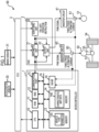
- FIG 1 is a configuration diagram showing an example of a motor control device 90.
- the motor control device 90 includes a microcontroller 1, an ASIC 2, an electronic control unit (ECU) 3, an accelerator sensor 30, and a brake sensor 31, and is mounted on an electrified vehicle such as a hybrid vehicle or an electric vehicle (hereinafter, referred to as a "vehicle").
- ECU electronice control unit
- the motor control device 90 controls inverter circuits 40, 41 connected to motors 50, 51, respectively.
- Each of the inverter circuits 40, 41 has, for example, a plurality of insulated gate bipolar transistors (IGBTs) corresponding to three-phase upper and lower arms. On/off control is performed for each IGBT by a pulse width modulation (PWM) signal received from ASIC 2 as an input.
- PWM pulse width modulation
- the inverter circuits 40, 41 generate three-phase alternating current in accordance with the PWM signals and output the three-phase alternating current to the motors 50, 51, respectively.
- the inverter circuits 40, 41 may have other types of transistors instead of the IGBT.
- the motors 50, 51 are driven by three-phase alternating current in accordance with the control of the motor control device 90.
- Current sensors 60, 61 that detect the current value of each phase of the three-phase alternating current are provided between the inverter circuits 40, 41 and the motors 50, 51, respectively.
- the current sensors 60, 61 notify the microcontroller 1 and the ASIC 2 of the current value.
- the motor 50 is used to drive the wheels (front wheels or rear wheels) 53, 54 of the vehicle, as an example.
- the motor 50 is connected to a differential gear 52 via a drive shaft 55.
- the differential gear 52 transmits the torque of the motor 50 to the wheels 53, 54 as a driving force corresponding to the reduction ratio unique to the vehicle type of the vehicle.
- the motor 51 is used, for example, to generate power. Note that the number of motors mounted on the vehicle is not limited.
- the accelerator sensor 30 detects the operation amount of an accelerator pedal of the vehicle and outputs the detected value to the ECU 3.
- the brake sensor 31 detects the operation amount of a brake pedal of the vehicle and outputs the detected value to the ECU 3.
- the ECU 3 is a computer device that generally controls the vehicle.
- the ECU 3 calculates the driving force requested for the vehicle (hereinafter, referred to as a "requested driving force") from the operation amount of the accelerator pedal, the operation amount of the brake pedal, and the like.
- the ECU 3 notifies the microcontroller 1 of the requested driving force.
- the microcontroller 1 has a CPU 10 that is an example of the processor, a read only memory (ROM) 11, a random access memory (RAM) 12, memories 13, 14, a communication port 15, and a hardware interface unit (HW-INF) 16.
- the CPU 10 is electrically connected to the ROM 11, the RAM 12, the memories 13, 14, the communication port 15, and the HW-INF 16 via a bus 19 such that signals can be input to and output from each other.
- the ROM 11 stores a program by which the CPU 10 is driven.
- the RAM 12 functions as a working memory of the CPU 10.
- the communication port 15 is used to communicate with the ASIC 2.
- the HW-INF 16 receives the current values of the three-phase alternating current from the current sensors 60, 61. The HW-INF 16 notifies the ASIC 2 of the current value via the CPU 10 or the communication port 15.
- the memory 13 is an example of the second storage unit, and stores a parameter (hereinafter, referred to as a "vehicle type parameter") 130 related to the vehicle type of the vehicle on which the motor control device 90 is mounted.
- vehicle type parameter 130 examples include the reduction ratio of the differential gear 52 connected to the motor 50, or a value related to the output performance of the motors 50, 51.
- the vehicle type parameter 130 is a parameter related to the specification unique to the vehicle type of the vehicle on which the motor control device 90 is mounted.
- the memory 14 is an example of the first storage unit, and stores characteristic map data 140 related to the drive control of each of the motors 50, 51.
- the characteristic map data 140 is an example of the characteristic data.
- the characteristic map data 140 includes, for example, rotation speed-torque map data indicating a correlation between the rotation speed and torque requested for the motors 50, 51 (hereinafter, referred to as "requested rotation speed” and “requested torque", respectively), and torque-current map data indicating a correlation between the requested torque and current command value of the three-phase current.
- the memories 13, 14 are non-volatile memories such as a flash memory.
- the vehicle type parameter 130 that is decided by the vehicle type of the vehicle that is a mounting target of the motor control device 90 is written in the memory 13, and the characteristic map data 140 corresponding to one or more vehicle types is written in the memory 14.
- the CPU 10 calculates the current command value of each of the motors 50, 51 based on the vehicle type parameter 130 and the characteristic map data 140 from the requested driving force, and calculates the voltage command value of each of the motors 50, 51 from the current command values and the current values acquired from the current sensors 60, 61. Further, the CPU 10 calculates on/off timing (hereinafter, referred to as "on/off timing") that decides the duty ratio of the PWM signal, from the voltage command value. The CPU 10 notifies the ASIC 2 of the on/off timing via the communication port 15.
- the on/off timing is an example of the result of the arithmetic processing. The details of the arithmetic processing will be described later.
- the ASIC 2 is an example of a drive circuit, and has a monitoring unit 20, an arithmetic unit 21, and an output unit 22.
- the output unit 22 executes drive processing of each of the motors 50, 51 based on the result of the arithmetic processing of the CPU 10.
- the output unit 22 receives notification of the on/off timing from the CPU 10 via the communication port 15.
- the output unit 22 generates the PWM signals in accordance with the on/off timing and outputs the PWM signals to the inverter circuits 40, 41.
- the monitoring unit 20 receives notification regarding the normality of the CPU 10 from the ECU 3.
- the ECU 3 monitors whether or not the CPU 10 is normally operated. For example, when the CPU 10 is normally operated, the monitoring unit 20 generates a pulse signal having a predetermined frequency from a clock signal received from an oscillator (not shown) as an input and transmits the pulse signal to the ECU 3.
- the ECU 3 determines the normality of the pulse signal received from the CPU 10. When the ECU 3 detects, for example, a stop of the pulse signal or the abnormality in the frequency of the pulse signal, the ECU 3 determines that abnormality has occurred in the CPU 10.
- the monitoring unit 20 determines whether or not abnormality has occurred in the CPU 10, based on the notification. When the monitoring unit 20 determines that abnormality has occurred in the CPU 10, the monitoring unit 20 instructs the arithmetic unit 21 and the output unit 22 to perform the fail-safe operation.
- the arithmetic unit 21 When the arithmetic unit 21 receives the instruction on the fail-safe operation from the monitoring unit 20, the arithmetic unit 21 executes the above-described arithmetic processing of the CPU 10 on behalf of the CPU 10. In this case, the arithmetic unit 21 acquires the vehicle type parameter 130 and the characteristic map data 140 from the memories 13, 14, respectively. At this time, the arithmetic unit 21 accesses the memories 13, 14 via the communication port 15 and reads out the vehicle type parameter 130 and the characteristic map data 140 from the memories 13, 14, respectively. Further, the arithmetic unit 21 acquires the current value of each phase of the three-phase alternating current from the current sensors 60, 61.
- the arithmetic unit 21 executes the arithmetic processing related to the drive control corresponding to the vehicle type of the vehicle on which the motor control device 90 is mounted in the same manner as the CPU 10 as normal, based on the vehicle type parameter 130 acquired from the memory 13 and the characteristic map data 140 acquired from the memory 14.
- the output unit 22 receives notification of the on/off timing from the arithmetic unit 21 on behalf of the CPU 10.
- the output unit 22 generates the PWM signals in accordance with the on/off timing and outputs the PWM signals to the inverter circuits 40, 41, as in a case where the CPU 10 is normal. With this, a fail-safe function when abnormality has occurred in the CPU 10 is realized.
- the memories 13, 14 are provided inside the microcontroller 1, but may be provided outside the microcontroller 1 and the ASIC 2.
- the CPU 10 and the ASIC 2 can access the memories 13, 14 via, for example, a separate bus.
- the vehicle type parameter 130 and the characteristic map data 140 may be stored on a common non-volatile memory.
- the storage area of the characteristic map data 140 and the storage area of the vehicle type parameter 130 in the memory are examples of the first and second storage units, respectively.
- the rotation speed-torque map data and the torque-current map data suitable for the drive control of the motors 50, 51 differ depending on the specification of each vehicle type. Therefore, the CPU 10 and the arithmetic unit 21 acquire the rotation speed-torque map data and the torque-current map data corresponding to the vehicle type of the vehicle on which the motor control device 90 is mounted from the characteristic map data 140, based on the vehicle type parameter 130, and use the acquired map data for the arithmetic processing.
- the rotation speed-torque map data and the torque-current map data when the vehicle type parameter 130 is the reduction ratio of the differential gear 52 will be described below as examples.
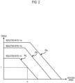
- FIG 2 is a diagram showing an example of rotation speed-torque map data Pa, Pb, Pc that correspond to a plurality of reduction ratios Ka, Kb, Kc of the differential gear 52, respectively, the reduction ratios being different from each other for each vehicle type.
- the rotation speed-torque map data Pa, Pb, Pc indicate the correlation between the rotation speed and the torque of the motors 50, 51.
- the rotation speed-torque map data Pa, Pb, Pc may be different from each other for each of the motors 50, 51 or may be common for the motors 50, 51.
- the rotation speed-torque map data Pa, Pb, Pc have a similar relationship with each other in accordance with the ratios of the reduction ratios Ka, Kb, Kc to each other.
- the rotation speed-torque map data Pa corresponding to the reduction ratio Ka shows the highest torque
- the rotation speed-torque map data Pc corresponding to the reduction ratio Kc shows the lowest torque.
- the CPU 10 and the arithmetic unit 21 use the rotation speed-torque map data Pa, Pb, Pc corresponding to a reduction ratio indicated by the vehicle type parameter 130, out of the reduction ratios Ka, Kb, Kc, for the arithmetic processing.
- the CPU 10 and the arithmetic unit 21 use the rotation speed-torque map data Pc corresponding to the reduction ratio Kc for the arithmetic processing.
- the CPU 10 and the arithmetic unit 21 calculate requested torque T corresponding to the rotation speed N from the rotation speed-torque map data Pc.
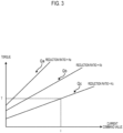
- FIG 3 is a diagram showing an example of torque-current map data Qa, Qb, Qc corresponding to the reduction ratios Ka, Kb, Kc of the differential gear 52, respectively, the reduction ratios being different from each other for each vehicle type.
- the torque-current map data Qa, Qb, Qc indicate the correlation between the current command values of the motors 50, 51 and the requested torque.
- the torque-current map data Qa, Qb, Qc may be different from each other for each of the motors 50, 51, or may be common for the motors 50, 51.
- the torque-current map data Qa, Qb, Qc have a similar relationship with each other in accordance with the ratios of the reduction ratios Ka, Kb, Kc to each other.
- the torque-current map data Qc corresponding to the reduction ratio Kc shows the highest current command value
- the torque-current map data Qa corresponding to the reduction ratio Ka shows the lowest current command value.
- the CPU 10 and the arithmetic unit 21 use the torque-current map data Qa, Qb, Qc corresponding to a reduction ratio indicated by the vehicle type parameter 130, out of the reduction ratios Ka, Kb, Kc, for the arithmetic processing.
- the CPU 10 and the arithmetic unit 21 use the torque-current map data Qc corresponding to the reduction ratio Kc for the arithmetic processing.
- the CPU 10 and the arithmetic unit 21 calculate a current command value I corresponding to the requested torque T from the torque-current map data Qc.
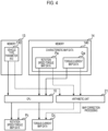
- FIG 4 is a diagram showing an example of the method of acquiring the rotation speed-torque map data Pc and the torque-current map data Qc corresponding to the vehicle type of the vehicle on which the motor control device 90 is mounted.
- the memory 13 stores, for example, the reduction ratio Kc as the vehicle type parameter 130 related to the vehicle type of the vehicle on which the motor control device 90 is mounted.
- the characteristic map data 140 stored on the memory 14 includes solely the rotation speed-torque map data Pa corresponding to the reduction ratio Ka, out of the rotation speed-torque map data Pa, Pb, Pc, and includes solely the torque-current map data Qa corresponding to the reduction ratio Ka, out of the torque-current map data Qa, Qb, Qc. That is, the memory 14 stores the torque-current map data Qa corresponding to the other vehicle type different from the vehicle type of the vehicle on which the motor control device 90 is mounted.
- the motors 50, 51 cannot be normally driven and controlled because the rotation speed-torque map data Pa and the torque-current map data Qa are not suitable for the characteristics of the vehicle type of the vehicle on which the motor control device 90 is mounted. As a result, the fail-safe function cannot be appropriately realized.
- the CPU 10 and the arithmetic unit 21 acquire the reduction ratio Kc and the rotation speed-torque map data Pa from the memories 13, 14, respectively, and correct the rotation speed-torque map data Pa based on reduction ratio Kc to acquire the rotation speed-torque map data Pc corresponding to the reduction ratio Kc.
- the CPU 10 and the arithmetic unit 21 multiply the rotation speed of the rotation speed-torque map data Pa by a constant based on the ratio of the reduction ratio Ka to the reduction ratio Kc, to obtain the rotation speed-torque map data Pc corresponding to the reduction ratio Kc.
- the CPU 10 and the arithmetic unit 21 hold the reduction ratio Ka corresponding to the rotation speed-torque map data Pa in advance as a fixed value.
- the CPU 10 and the arithmetic unit 21 acquire the torque-current map data Qa from the memory 14, and correct the torque-current map data Qa based on the reduction ratio Kc to acquire the torque-current map data Qc corresponding to the reduction ratio Kc. For example, the CPU 10 and the arithmetic unit 21 multiply the current command value of the torque-current map data Qa by a constant based on the ratio of the reduction ratio Ka to the reduction ratio Kc, to obtain the torque-current map data Qc corresponding to the reduction ratio Kc.
- the CPU 10 and the arithmetic unit 21 correct the rotation speed-torque map data Pa and the torque-current map data Qa such that the rotation speed-torque map data Pa and the torque-current map data Qa correspond to the vehicle type of the vehicle on which the motor control device 90 is mounted, based on the vehicle type parameter 130, and use the corrected map data for the arithmetic processing.
- FIG 5 is a diagram showing another example of the method of acquiring the rotation speed-torque map data Pa, Pb, Pc and the torque-current map data Qa, Qb, Qc.
- the motor control device 90 is mounted on a vehicle of the vehicle type of the reduction ratio Kc. Therefore, the memory 13 stores, for example, the reduction ratio Kc as the vehicle type parameter 130 related to the vehicle type of the vehicle on which the motor control device 90 is mounted.
- the characteristic map data 140 stored on the memory 14 includes the rotation speed-torque map data Pa, Pb, Pc and the torque-current map data Qa, Qb, Qc corresponding to the reduction ratios Ka, Kb, Kc related to a plurality of vehicle types, respectively.
- the characteristic map data 140 also includes the rotation speed-torque map data Pa, Pb and the torque-current map data Qa, Qb other than the vehicle type of the vehicle on which the motor control device 90 is mounted. That is, the memory 14 stores the characteristic map data 140 corresponding to the plurality of vehicle types.
- the CPU 10 and the arithmetic unit 21 acquire the reduction ratio Kc from the memory 13.
- the CPU 10 and the arithmetic unit 21 select and acquire solely the rotation speed-torque map data Pc corresponding to the reduction ratio Kc out of the rotation speed-torque map data Pa, Pb, Pc stored on the memory 14.
- the CPU 10 and the ASIC 2 read out the rotation speed-torque map data Pc from, for example, the storage area corresponding to the reduction ratio Kc out of the storage areas of the memory 14.
- the CPU 10 and the arithmetic unit 21 select and acquire solely the torque-current map data Qc corresponding to the reduction ratio Kc out of the torque-current map data Qa, Qb, Qc stored on the memory 14. Specifically, the CPU 10 and the arithmetic unit 21 read out the torque-current map data Qc from, for example, the storage area corresponding to the reduction ratio Kc out of the storage areas of the memory 14.
- the CPU 10 and the arithmetic unit 21 read out, from the memory 14, the rotation speed-torque map data Pc and the torque-current map data Qc corresponding to the vehicle type of the vehicle on which the motor control device 90 is mounted, out of the plurality of vehicle types, based on the vehicle type parameter 130 and use the read-out map data for the arithmetic processing.
- the CPU 10 and the arithmetic unit 21 can acquire the rotation speed-torque map data Pc and the torque-current map data Qc corresponding to the reduction ratio Kc of the vehicle type of the vehicle on which the motor control device 90 is mounted. Therefore, the CPU 10 and the arithmetic unit 21 can calculate an appropriate requested torque and current command value corresponding to the reduction ratio Kc.
- the capacity of the memory 14 can be reduced because the amount of data of the characteristic map data 140 stored on the memory 14 is smaller than the amount of data in the case of the example of FIG 5 .
- the CPU 10 and the arithmetic unit 21 it is unnecessary for the CPU 10 and the arithmetic unit 21 to perform the correction processing of the rotation speed-torque map data Pa and the torque-current map data Qa, so that the load of the arithmetic processing can be reduced.
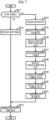
- FIG 6 is a flowchart showing an example of the operation of the CPU 10. Steps St2 to St8 described below are examples of the arithmetic processing related to the drive control of the motors 50, 51 corresponding to the vehicle type of the vehicle on which the motor control device 90 is mounted.
- the CPU 10 receives notification of the requested driving force from the ECU 3 (step St1). Next, the CPU 10 acquires the vehicle type parameter 130 from the memory 13 (step St2).
- the CPU 10 first reads out the rotation speed-torque map data, out of the characteristic map data 140, from the memory 14 (step St3). Next, the CPU 10 calculates the requested torque corresponding to the rotation speed of the motors 50, 51 satisfying the requested driving force, from the vehicle type parameter 130 and the rotation speed-torque map data (step St4).
- the CPU 10 acquires, based on the vehicle type parameter 130, the rotation speed-torque map data corresponding to the vehicle type of the vehicle on which the motor control device 90 is mounted, in accordance with the acquisition method described with reference to FIG 4 or 5 .
- the CPU 10 obtains the requested torque corresponding to the rotation speed of the motors 50, 51 from the rotation speed-torque map data corresponding to the vehicle type of the vehicle on which the motor control device 90 is mounted.
- the CPU 10 reads out the torque-current map data, out of the characteristic map data 140, from the memory 14 (step St5).
- the CPU 10 calculates the current command value of three-phase alternating current satisfying the requested torque, from the vehicle type parameter 130 and the torque-current map data (step St6).
- the CPU 10 acquires, based on the vehicle type parameter 130, the torque-current map data corresponding to the vehicle type of the vehicle on which the motor control device 90 is mounted, in accordance with the acquisition method described with reference to FIG 4 or 5 . Further, the CPU 10 obtains the current command value of three-phase alternating current satisfying the requested torque, from the torque-current map data corresponding to the vehicle type of the vehicle on which the motor control device 90 is mounted.
- the CPU 10 calculates the voltage command values of the motors 50, 51 from the current command values (step St7). At this time, the CPU 10 acquires the current value of the three-phase alternating current from the current sensors 60, 61 via the HW-INF 16. The CPU 10 decides the current command value by PI control, for example, in accordance with the difference between the current command value and the current value of the current sensor.
- the CPU 10 performs duty arithmetic of the PWM signal from the voltage command value (step St8).
- the CPU 10 generates a carrier signal that changes in a triangular wave shape on the time axis, and compares the voltage command value that changes in a sine wave shape with the signal value of the carrier signal.
- the carrier signal is a signal that is used to decide the on/off timing of the PWM signal.
- the PWM signal is turned off when the signal value of the carrier signal is the voltage command value or more, and the PWM signal is turned on when the signal value of the carrier signal is less than the voltage command value.
- the CPU 10 calculates time Ton when the PWM signal is turned on and time Toff when the PWM signal is turned off.
- the duty ratio of the PWM signal is decided by time Ton and Toff.
- the CPU 10 executes arithmetic processing related to the drive control of the motors 50, 51 corresponding to the vehicle type of the vehicle on which the motor control device 90 is mounted, based on the vehicle type parameter 130 and the characteristic map data 140.
- the CPU 10 notifies the output unit 22 of the ASIC 2, via the communication port 15, of the on/off timing as a result of the arithmetic processing, that is, time Ton and Toff (step St9). In this way, the CPU 10 is operated.
- FIG 7 is a flowchart showing an example of the operation of the ASIC 2.
- Steps St15 to St21 described below are examples of the arithmetic processing related to the drive control of the motors 50, 51 corresponding to the vehicle type of the vehicle on which the motor control device 90 is mounted.
- step St13 described below is an example of the drive processing of the motors 50, 51 of the vehicle on which the motor control device 90 is mounted.
- the monitoring unit 20 of the ASIC 2 determines whether or not the operation of the CPU 10 is normal, based on the notification from the ECU 3 (step St11).
- the monitoring unit 20 may directly determine the normality of the CPU 10 by communicating with the CPU 10, without going through the ECU 3.
- the output unit 22 receives notification of the on/off timing from the CPU 10 (step St12). Next, the output unit 22 generates the PWM signals (see reference numeral G in FIG 6 ) based on the on/off timing and outputs the PWM signals to the inverter circuits 40, 41 (step St13). As described above, when the operation of the CPU 10 is normal, the ASIC 2 executes generation processing and output processing of the PWM signal based on the result of the arithmetic processing of the CPU 10 regardless of the type of vehicle, out of the control for the motors 50, 51.
- the ASIC 2 performs the arithmetic processing of following steps St14 to St21 on behalf of the CPU 10, in order to realize the fail-safe function.
- the arithmetic unit 21 receives notification of the requested driving force from the ECU 3 (step St14). Next, the ASIC 2 acquires the vehicle type parameter 130 from the memory 13 (step St15).
- the arithmetic unit 21 first reads out the rotation speed-torque map data, out of the characteristic map data 140, from the memory 14 (step St16). Next, the arithmetic unit 21 calculates the requested torque corresponding to the rotation speed of the motors 50, 51 satisfying the requested driving force, from the vehicle type parameter 130 and the rotation speed-torque map data (step St17).
- the arithmetic unit 21 acquires, based on the vehicle type parameter 130, the rotation speed-torque map data corresponding to the vehicle type of the vehicle on which the motor control device 90 is mounted, in accordance with the acquisition method described with reference to FIG 4 or 5 . Further, the arithmetic unit 21 obtains the requested torque corresponding to the rotation speed of the motors 50, 51 from the rotation speed-torque map data corresponding to the vehicle type of the vehicle on which the motor control device 90 is mounted.
- the arithmetic unit 21 reads out the torque-current map data, out of the characteristic map data 140, from the memory 14 (step St18). Next, the arithmetic unit 21 calculates the current command value of the three-phase alternating current satisfying the requested torque, from the vehicle type parameter 130 and the torque-current map data (step St19).
- the arithmetic unit 21 acquires, based on the vehicle type parameter 130, the torque-current map data corresponding to the vehicle type of the vehicle on which the motor control device 90 is mounted, in accordance with the acquisition method described with reference to FIG 4 or 5 . Further, the arithmetic unit 21 obtains the current command value of three-phase alternating current satisfying the requested torque, from the torque-current map data corresponding to the vehicle type of the vehicle on which the motor control device 90 is mounted.
- the arithmetic unit 21 calculates the voltage command values of the motors 50, 51 from the current command values (step St20). At this time, the arithmetic unit 21 acquires the current values of the three-phase alternating current from the current sensors 60, 61. The arithmetic unit 21 decides the current command value by PI control, for example, in accordance with the difference between the current command value and the current value of the current sensor.
- the arithmetic unit 21 performs duty arithmetic of the PWM signal from the voltage command value (step St21). At this time, as described with reference to the reference numeral G in FIG 6 , the arithmetic unit 21 compares the signal value of the carrier signal with the voltage command value to calculate time Ton when the PWM signal is turned on and time Toff when the PWM signal is turned off, as the on/off timing.
- the arithmetic unit 21 generates the PWM signals based on the on/off timing and outputs the PWM signals to the inverter circuits 40, 41 (step St13).
- the ASIC 2 execute the arithmetic processing corresponding to the type of the vehicle on which the motor control device 90 is mounted based on the vehicle type parameter 130 and the characteristic map data 140 that are read out from the memories 13, 14, respectively.
- the motor control device 90 can continue the drive control of the motors 50, 51 corresponding to the characteristics of the vehicle type of the vehicle on which the motor control device 90 is mounted, even when abnormality has occurred in the CPU 10. Further, since the memories 13, 14 are provided outside the ASIC 2, an increase in device cost is restrained. Accordingly, the motor control device 90 can restrain the increase in device cost and appropriately realize the fail-safe function in response to the vehicle type.
Landscapes
- Engineering & Computer Science (AREA)
- Transportation (AREA)
- Mechanical Engineering (AREA)
- Power Engineering (AREA)
- Automation & Control Theory (AREA)
- Sustainable Energy (AREA)
- Life Sciences & Earth Sciences (AREA)
- Sustainable Development (AREA)
- Human Computer Interaction (AREA)
- Chemical & Material Sciences (AREA)
- Combustion & Propulsion (AREA)
- Electric Propulsion And Braking For Vehicles (AREA)
- Control Of Electric Motors In General (AREA)
Description
- The present invention relates to a motor control device and a motor control method.
- For example, an electrified vehicle such as a hybrid vehicle and an electric vehicle is provided with a plurality of motors such as a motor for driving front wheels or rear wheels and a motor for generating power. A control device of each motor executes control processing by distributing the load for each motor by, for example, a plurality of microcontrollers having a built-in processor such as a central processing unit (CPU) (for example,
Japanese Unexamined Patent Application Publication No. 2018-109951 JP 2018-109951 A - One microcontroller executes, when abnormality has occurred in the other microcontroller, the control processing on behalf of the other microcontroller to operate the motor normally. With this, a fail-safe function is realized.
- Document
JP 6 777623 B2 -
US 2016/0373051 A1 discloses a motor bridge driver integrated circuit. -
US 2013/0116876 A1 discloses an electric vehicle and a method for controlling an emergency thereof. - When the control processing of the plurality of motors is integrated into one microcontroller, the load of the control processing of the processor built in the microcontroller increases. Therefore, it is conceivable that a part of the control processing is shared with, for example, an application specific integrated circuit (ASIC). In this case, the ASIC realizes the fail-safe function by executing the control processing of the microcontroller when abnormality has occurred in the microcontroller.
- In addition, in order to make it possible to mount the microcontroller on a plurality of vehicle types of vehicles, the microcontroller executes control processing by switching, using software, characteristic data related to motor drive control in response to a vehicle type of a vehicle that is a mounting target. However, in order to reduce the device cost, the ASIC does not have a built-in memory that stores characteristic data corresponding to the plurality of vehicle types in advance, so that the ASIC can execute solely control processing in accordance with the characteristics of a specific vehicle type.
- Therefore, in a case where the ASIC is used for a vehicle of a vehicle type that the ASIC does not support, the control device cannot normally drive and control the motor in accordance with the characteristics corresponding to the vehicle type of the vehicle on which the control device is mounted when abnormality has occurred in the microcontroller, so that the fail-safe function cannot be appropriately realized.
- In that regard, the present invention provides a motor control device capable of restraining an increase in device cost and appropriately realizing a fail-safe function in response to a vehicle type.
- A first aspect of the invention relates to a motor control device including a first storage unit, a second storage unit, a processor, and a drive circuit. The first storage unit is configured to store characteristic data related to drive control of a motor of a plurality of vehicle types. The second storage unit is configured to store a vehicle type parameter related to a predetermined vehicle type, wherein the vehicle type parameter is a reduction ratio of a differential gear connected to the motor. The processor is configured to execute arithmetic processing related to the drive control corresponding to the predetermined vehicle type, based on the vehicle type parameter and the characteristic data. The drive circuit is configured to execute a drive processing of a motor of a vehicle of the predetermined vehicle type, based on a result of the arithmetic processing. The drive circuit is configured to read out the characteristic data from the first storage unit and the vehicle type parameter from the second storage unit when abnormality has occurred in the processor, and to execute the arithmetic processing related to the drive control corresponding to the predetermined vehicle type, based on the vehicle type parameter and the characteristic data.
- In the motor control device according to the first aspect, the first storage unit may be configured to store the characteristic data corresponding to the other vehicle type different from the predetermined vehicle type. The drive circuit may be configured to correct the characteristic data such that the characteristic data corresponds to the predetermined vehicle type, based on the vehicle type parameter, when abnormality has occurred in the processor and to use the corrected characteristic data for the arithmetic processing.
- The drive circuit may be configured to read out, from the first storage unit, the characteristic data corresponding to the predetermined vehicle type out of the plurality of vehicle types based on the vehicle type parameter, and to use the characteristic data for the arithmetic processing.
- In the motor control device according to the first aspect, the characteristic data may include a correlation between rotation speed and torque of the motor.
- In the motor control device according to the first aspect, the characteristic data may include a correlation between torque and a current value of the motor.
- In the motor control device according to the first aspect, the drive circuit may be configured to receive notification regarding normality of the processor. The drive circuit may be configured to determine whether or not abnormality has occurred in the processor, based on the notification.
- A second aspect of the invention relates to a motor control method. The motor control method includes determining, by a drive circuit, whether or not abnormality has occurred in a processor configured to execute arithmetic processing related to drive control corresponding to a predetermined vehicle type, wherein the vehicle type parameter is a reduction ratio of a differential gear connected to the motor, based on a vehicle type parameter related to drive control of a motor of a vehicle and characteristic data related to the predetermined vehicle type; reading out, by the drive circuit, the characteristic data from a first storage unit configured to store the characteristic data and the vehicle type parameter from a second storage unit configured to store the vehicle type parameter when the drive circuit determines that abnormality has occurred in the processor; and executing, by the drive circuit, the arithmetic processing related to the drive control corresponding to the predetermined vehicle type, based on the vehicle type parameter and the characteristic data.
- According to the above-described aspects of the present invention, it is possible to restrain an increase in device cost and appropriately realize a fail-safe function in response to a vehicle type.
- Features, advantages, and technical and industrial significance of exemplary embodiments of the invention will be described below with reference to the accompanying drawings, in which like signs denote like elements, and wherein:
-
FIG 1 is a configuration diagram showing an example of a motor control device; -
FIG 2 is a diagram showing an example of rotation speed-torque map data corresponding to a plurality of reduction ratios of a differential gear, the reduction ratios being different from each other for each vehicle type; -
FIG 3 is a diagram showing an example of torque-current map data corresponding to the reduction ratios of the differential gear, the reduction ratios being different from each other for each vehicle type; -
FIG 4 is a diagram showing an example of a method of acquiring rotation speed-torque map data and torque-current map data corresponding to the vehicle type of a vehicle on which the motor control device is mounted; -
FIG 5 is a diagram showing another example of the method of acquiring rotation speed-torque map data and torque-current map data; -
FIG 6 is a flowchart showing an example of operation of a CPU; and -
FIG 7 is a flowchart showing an example of operation of an ASIC. -
FIG 1 is a configuration diagram showing an example of amotor control device 90. Themotor control device 90 includes a microcontroller 1, an ASIC 2, an electronic control unit (ECU) 3, anaccelerator sensor 30, and abrake sensor 31, and is mounted on an electrified vehicle such as a hybrid vehicle or an electric vehicle (hereinafter, referred to as a "vehicle"). - The
motor control device 90controls inverter circuits motors inverter circuits - The
inverter circuits motors inverter circuits - The
motors motor control device 90.Current sensors inverter circuits motors current sensors - The
motor 50 is used to drive the wheels (front wheels or rear wheels) 53, 54 of the vehicle, as an example. Themotor 50 is connected to adifferential gear 52 via adrive shaft 55. Thedifferential gear 52 transmits the torque of themotor 50 to thewheels motor 51 is used, for example, to generate power. Note that the number of motors mounted on the vehicle is not limited. - The
accelerator sensor 30 detects the operation amount of an accelerator pedal of the vehicle and outputs the detected value to the ECU 3. Thebrake sensor 31 detects the operation amount of a brake pedal of the vehicle and outputs the detected value to the ECU 3. - The ECU 3 is a computer device that generally controls the vehicle. The ECU 3 calculates the driving force requested for the vehicle (hereinafter, referred to as a "requested driving force") from the operation amount of the accelerator pedal, the operation amount of the brake pedal, and the like. The ECU 3 notifies the microcontroller 1 of the requested driving force.
- The microcontroller 1 has a
CPU 10 that is an example of the processor, a read only memory (ROM) 11, a random access memory (RAM) 12,memories communication port 15, and a hardware interface unit (HW-INF) 16. TheCPU 10 is electrically connected to theROM 11, theRAM 12, thememories communication port 15, and the HW-INF 16 via abus 19 such that signals can be input to and output from each other. - The
ROM 11 stores a program by which theCPU 10 is driven. TheRAM 12 functions as a working memory of theCPU 10. Thecommunication port 15 is used to communicate with the ASIC 2. The HW-INF 16 receives the current values of the three-phase alternating current from thecurrent sensors INF 16 notifies the ASIC 2 of the current value via theCPU 10 or thecommunication port 15. - The
memory 13 is an example of the second storage unit, and stores a parameter (hereinafter, referred to as a "vehicle type parameter") 130 related to the vehicle type of the vehicle on which themotor control device 90 is mounted. Examples of thevehicle type parameter 130 include the reduction ratio of thedifferential gear 52 connected to themotor 50, or a value related to the output performance of themotors vehicle type parameter 130 is a parameter related to the specification unique to the vehicle type of the vehicle on which themotor control device 90 is mounted. - The
memory 14 is an example of the first storage unit, and storescharacteristic map data 140 related to the drive control of each of themotors characteristic map data 140 is an example of the characteristic data. Thecharacteristic map data 140 includes, for example, rotation speed-torque map data indicating a correlation between the rotation speed and torque requested for themotors 50, 51 (hereinafter, referred to as "requested rotation speed" and "requested torque", respectively), and torque-current map data indicating a correlation between the requested torque and current command value of the three-phase current. - The
memories motor control device 90, thevehicle type parameter 130 that is decided by the vehicle type of the vehicle that is a mounting target of themotor control device 90 is written in thememory 13, and thecharacteristic map data 140 corresponding to one or more vehicle types is written in thememory 14. - The
CPU 10 reads a program from theROM 11 and is operated in accordance with the program. TheCPU 10 receives the requested driving force from the ECU 3, and executes arithmetic processing related to the drive control of themotors motor control device 90 is mounted based on thevehicle type parameter 130 and thecharacteristic map data 140 such that the requested driving force is satisfied. - In the arithmetic processing, the
CPU 10 calculates the current command value of each of themotors vehicle type parameter 130 and thecharacteristic map data 140 from the requested driving force, and calculates the voltage command value of each of themotors current sensors CPU 10 calculates on/off timing (hereinafter, referred to as "on/off timing") that decides the duty ratio of the PWM signal, from the voltage command value. TheCPU 10 notifies the ASIC 2 of the on/off timing via thecommunication port 15. The on/off timing is an example of the result of the arithmetic processing. The details of the arithmetic processing will be described later. - The ASIC 2 is an example of a drive circuit, and has a
monitoring unit 20, anarithmetic unit 21, and anoutput unit 22. Theoutput unit 22 executes drive processing of each of themotors CPU 10. Theoutput unit 22 receives notification of the on/off timing from theCPU 10 via thecommunication port 15. Theoutput unit 22 generates the PWM signals in accordance with the on/off timing and outputs the PWM signals to theinverter circuits - The
monitoring unit 20 receives notification regarding the normality of theCPU 10 from the ECU 3. The ECU 3 monitors whether or not theCPU 10 is normally operated. For example, when theCPU 10 is normally operated, themonitoring unit 20 generates a pulse signal having a predetermined frequency from a clock signal received from an oscillator (not shown) as an input and transmits the pulse signal to the ECU 3. The ECU 3 determines the normality of the pulse signal received from theCPU 10. When the ECU 3 detects, for example, a stop of the pulse signal or the abnormality in the frequency of the pulse signal, the ECU 3 determines that abnormality has occurred in theCPU 10. - The
monitoring unit 20 determines whether or not abnormality has occurred in theCPU 10, based on the notification. When themonitoring unit 20 determines that abnormality has occurred in theCPU 10, themonitoring unit 20 instructs thearithmetic unit 21 and theoutput unit 22 to perform the fail-safe operation. - When the
arithmetic unit 21 receives the instruction on the fail-safe operation from themonitoring unit 20, thearithmetic unit 21 executes the above-described arithmetic processing of theCPU 10 on behalf of theCPU 10. In this case, thearithmetic unit 21 acquires thevehicle type parameter 130 and thecharacteristic map data 140 from thememories arithmetic unit 21 accesses thememories communication port 15 and reads out thevehicle type parameter 130 and thecharacteristic map data 140 from thememories arithmetic unit 21 acquires the current value of each phase of the three-phase alternating current from thecurrent sensors - The
arithmetic unit 21 executes the arithmetic processing related to the drive control corresponding to the vehicle type of the vehicle on which themotor control device 90 is mounted in the same manner as theCPU 10 as normal, based on thevehicle type parameter 130 acquired from thememory 13 and thecharacteristic map data 140 acquired from thememory 14. - The
output unit 22 receives notification of the on/off timing from thearithmetic unit 21 on behalf of theCPU 10. Theoutput unit 22 generates the PWM signals in accordance with the on/off timing and outputs the PWM signals to theinverter circuits CPU 10 is normal. With this, a fail-safe function when abnormality has occurred in theCPU 10 is realized. - In the present example, the
memories CPU 10 and the ASIC 2 can access thememories vehicle type parameter 130 and thecharacteristic map data 140 may be stored on a common non-volatile memory. In this case, the storage area of thecharacteristic map data 140 and the storage area of thevehicle type parameter 130 in the memory are examples of the first and second storage units, respectively. - Next, the
vehicle type parameter 130 and thecharacteristic map data 140 will be described. The rotation speed-torque map data and the torque-current map data suitable for the drive control of themotors CPU 10 and thearithmetic unit 21 acquire the rotation speed-torque map data and the torque-current map data corresponding to the vehicle type of the vehicle on which themotor control device 90 is mounted from thecharacteristic map data 140, based on thevehicle type parameter 130, and use the acquired map data for the arithmetic processing. The rotation speed-torque map data and the torque-current map data when thevehicle type parameter 130 is the reduction ratio of thedifferential gear 52 will be described below as examples. -
FIG 2 is a diagram showing an example of rotation speed-torque map data Pa, Pb, Pc that correspond to a plurality of reduction ratios Ka, Kb, Kc of thedifferential gear 52, respectively, the reduction ratios being different from each other for each vehicle type. The rotation speed-torque map data Pa, Pb, Pc indicate the correlation between the rotation speed and the torque of themotors motors motors - For example, the rotation speed-torque map data Pa, Pb, Pc have a similar relationship with each other in accordance with the ratios of the reduction ratios Ka, Kb, Kc to each other. For a certain rotation speed, out of the rotation speed-torque map data Pa, Pb, Pc, the rotation speed-torque map data Pa corresponding to the reduction ratio Ka shows the highest torque, and the rotation speed-torque map data Pc corresponding to the reduction ratio Kc shows the lowest torque.
- The
CPU 10 and thearithmetic unit 21 use the rotation speed-torque map data Pa, Pb, Pc corresponding to a reduction ratio indicated by thevehicle type parameter 130, out of the reduction ratios Ka, Kb, Kc, for the arithmetic processing. As an example, when thevehicle type parameter 130 indicates the reduction ratio Kc, theCPU 10 and thearithmetic unit 21 use the rotation speed-torque map data Pc corresponding to the reduction ratio Kc for the arithmetic processing. In this case, when the rotation speed satisfying the requested driving force of which the ECU 3 has notified theCPU 10 and thearithmetic unit 21 is N, theCPU 10 and thearithmetic unit 21 calculate requested torque T corresponding to the rotation speed N from the rotation speed-torque map data Pc. -
FIG 3 is a diagram showing an example of torque-current map data Qa, Qb, Qc corresponding to the reduction ratios Ka, Kb, Kc of thedifferential gear 52, respectively, the reduction ratios being different from each other for each vehicle type. The torque-current map data Qa, Qb, Qc indicate the correlation between the current command values of themotors motors motors - For example, the torque-current map data Qa, Qb, Qc have a similar relationship with each other in accordance with the ratios of the reduction ratios Ka, Kb, Kc to each other. For a certain requested torque, out of the torque-current map data Qa, Qb, Qc, the torque-current map data Qc corresponding to the reduction ratio Kc shows the highest current command value, and the torque-current map data Qa corresponding to the reduction ratio Ka shows the lowest current command value.
- The
CPU 10 and thearithmetic unit 21 use the torque-current map data Qa, Qb, Qc corresponding to a reduction ratio indicated by thevehicle type parameter 130, out of the reduction ratios Ka, Kb, Kc, for the arithmetic processing. As an example, when thevehicle type parameter 130 indicates the reduction ratio Kc, theCPU 10 and thearithmetic unit 21 use the torque-current map data Qc corresponding to the reduction ratio Kc for the arithmetic processing. In this case, when the requested torque is T, theCPU 10 and thearithmetic unit 21 calculate a current command value I corresponding to the requested torque T from the torque-current map data Qc. - Next, a method of acquiring rotation speed-torque map data and torque-current map data corresponding to the vehicle type of the vehicle on which the
motor control device 90 is mounted will be described. -
FIG 4 is a diagram showing an example of the method of acquiring the rotation speed-torque map data Pc and the torque-current map data Qc corresponding to the vehicle type of the vehicle on which themotor control device 90 is mounted. In the present example, it is assumed that themotor control device 90 is mounted on a vehicle of the vehicle type of the reduction ratio Kc. Therefore, thememory 13 stores, for example, the reduction ratio Kc as thevehicle type parameter 130 related to the vehicle type of the vehicle on which themotor control device 90 is mounted. - Further, the
characteristic map data 140 stored on thememory 14 includes solely the rotation speed-torque map data Pa corresponding to the reduction ratio Ka, out of the rotation speed-torque map data Pa, Pb, Pc, and includes solely the torque-current map data Qa corresponding to the reduction ratio Ka, out of the torque-current map data Qa, Qb, Qc. That is, thememory 14 stores the torque-current map data Qa corresponding to the other vehicle type different from the vehicle type of the vehicle on which themotor control device 90 is mounted. - If the
CPU 10 and thearithmetic unit 21 use the rotation speed-torque map data Pa and the torque-current map data Qa for the arithmetic processing, themotors motor control device 90 is mounted. As a result, the fail-safe function cannot be appropriately realized. - For this reason, the
CPU 10 and thearithmetic unit 21 acquire the reduction ratio Kc and the rotation speed-torque map data Pa from thememories CPU 10 and thearithmetic unit 21 multiply the rotation speed of the rotation speed-torque map data Pa by a constant based on the ratio of the reduction ratio Ka to the reduction ratio Kc, to obtain the rotation speed-torque map data Pc corresponding to the reduction ratio Kc. Here, theCPU 10 and thearithmetic unit 21 hold the reduction ratio Ka corresponding to the rotation speed-torque map data Pa in advance as a fixed value. - Further, the
CPU 10 and thearithmetic unit 21 acquire the torque-current map data Qa from thememory 14, and correct the torque-current map data Qa based on the reduction ratio Kc to acquire the torque-current map data Qc corresponding to the reduction ratio Kc. For example, theCPU 10 and thearithmetic unit 21 multiply the current command value of the torque-current map data Qa by a constant based on the ratio of the reduction ratio Ka to the reduction ratio Kc, to obtain the torque-current map data Qc corresponding to the reduction ratio Kc. - In this way, the
CPU 10 and thearithmetic unit 21 correct the rotation speed-torque map data Pa and the torque-current map data Qa such that the rotation speed-torque map data Pa and the torque-current map data Qa correspond to the vehicle type of the vehicle on which themotor control device 90 is mounted, based on thevehicle type parameter 130, and use the corrected map data for the arithmetic processing. -
FIG 5 is a diagram showing another example of the method of acquiring the rotation speed-torque map data Pa, Pb, Pc and the torque-current map data Qa, Qb, Qc. In the present example, it is assumed that themotor control device 90 is mounted on a vehicle of the vehicle type of the reduction ratio Kc. Therefore, thememory 13 stores, for example, the reduction ratio Kc as thevehicle type parameter 130 related to the vehicle type of the vehicle on which themotor control device 90 is mounted. - Further, the
characteristic map data 140 stored on thememory 14 includes the rotation speed-torque map data Pa, Pb, Pc and the torque-current map data Qa, Qb, Qc corresponding to the reduction ratios Ka, Kb, Kc related to a plurality of vehicle types, respectively. Thecharacteristic map data 140 also includes the rotation speed-torque map data Pa, Pb and the torque-current map data Qa, Qb other than the vehicle type of the vehicle on which themotor control device 90 is mounted. That is, thememory 14 stores thecharacteristic map data 140 corresponding to the plurality of vehicle types. - The
CPU 10 and thearithmetic unit 21 acquire the reduction ratio Kc from thememory 13. TheCPU 10 and thearithmetic unit 21 select and acquire solely the rotation speed-torque map data Pc corresponding to the reduction ratio Kc out of the rotation speed-torque map data Pa, Pb, Pc stored on thememory 14. Specifically, theCPU 10 and the ASIC 2 read out the rotation speed-torque map data Pc from, for example, the storage area corresponding to the reduction ratio Kc out of the storage areas of thememory 14. - Further, the
CPU 10 and thearithmetic unit 21 select and acquire solely the torque-current map data Qc corresponding to the reduction ratio Kc out of the torque-current map data Qa, Qb, Qc stored on thememory 14. Specifically, theCPU 10 and thearithmetic unit 21 read out the torque-current map data Qc from, for example, the storage area corresponding to the reduction ratio Kc out of the storage areas of thememory 14. - As described above, the
CPU 10 and thearithmetic unit 21 read out, from thememory 14, the rotation speed-torque map data Pc and the torque-current map data Qc corresponding to the vehicle type of the vehicle on which themotor control device 90 is mounted, out of the plurality of vehicle types, based on thevehicle type parameter 130 and use the read-out map data for the arithmetic processing. - In this way, the
CPU 10 and thearithmetic unit 21 can acquire the rotation speed-torque map data Pc and the torque-current map data Qc corresponding to the reduction ratio Kc of the vehicle type of the vehicle on which themotor control device 90 is mounted. Therefore, theCPU 10 and thearithmetic unit 21 can calculate an appropriate requested torque and current command value corresponding to the reduction ratio Kc. - Further, in the case of the example of
FIG 4 , the capacity of thememory 14 can be reduced because the amount of data of thecharacteristic map data 140 stored on thememory 14 is smaller than the amount of data in the case of the example ofFIG 5 . On the other hand, in the case of the example ofFIG 5 unlike the case of the example ofFIG 4 , it is unnecessary for theCPU 10 and thearithmetic unit 21 to perform the correction processing of the rotation speed-torque map data Pa and the torque-current map data Qa, so that the load of the arithmetic processing can be reduced. -
FIG 6 is a flowchart showing an example of the operation of theCPU 10. Steps St2 to St8 described below are examples of the arithmetic processing related to the drive control of themotors motor control device 90 is mounted. - The
CPU 10 receives notification of the requested driving force from the ECU 3 (step St1). Next, theCPU 10 acquires thevehicle type parameter 130 from the memory 13 (step St2). - Next, the
CPU 10 first reads out the rotation speed-torque map data, out of thecharacteristic map data 140, from the memory 14 (step St3). Next, theCPU 10 calculates the requested torque corresponding to the rotation speed of themotors vehicle type parameter 130 and the rotation speed-torque map data (step St4). - At this time, the
CPU 10 acquires, based on thevehicle type parameter 130, the rotation speed-torque map data corresponding to the vehicle type of the vehicle on which themotor control device 90 is mounted, in accordance with the acquisition method described with reference toFIG 4 or5 . TheCPU 10 obtains the requested torque corresponding to the rotation speed of themotors motor control device 90 is mounted. - Next, the
CPU 10 reads out the torque-current map data, out of thecharacteristic map data 140, from the memory 14 (step St5). Next, theCPU 10 calculates the current command value of three-phase alternating current satisfying the requested torque, from thevehicle type parameter 130 and the torque-current map data (step St6). - At this time, the
CPU 10 acquires, based on thevehicle type parameter 130, the torque-current map data corresponding to the vehicle type of the vehicle on which themotor control device 90 is mounted, in accordance with the acquisition method described with reference toFIG 4 or5 . Further, theCPU 10 obtains the current command value of three-phase alternating current satisfying the requested torque, from the torque-current map data corresponding to the vehicle type of the vehicle on which themotor control device 90 is mounted. - Next, the
CPU 10 calculates the voltage command values of themotors CPU 10 acquires the current value of the three-phase alternating current from thecurrent sensors INF 16. TheCPU 10 decides the current command value by PI control, for example, in accordance with the difference between the current command value and the current value of the current sensor. - Next, the
CPU 10 performs duty arithmetic of the PWM signal from the voltage command value (step St8). At this time, as indicated by the reference numeral G, theCPU 10 generates a carrier signal that changes in a triangular wave shape on the time axis, and compares the voltage command value that changes in a sine wave shape with the signal value of the carrier signal. The carrier signal is a signal that is used to decide the on/off timing of the PWM signal. The PWM signal is turned off when the signal value of the carrier signal is the voltage command value or more, and the PWM signal is turned on when the signal value of the carrier signal is less than the voltage command value. TheCPU 10 calculates time Ton when the PWM signal is turned on and time Toff when the PWM signal is turned off. The duty ratio of the PWM signal is decided by time Ton and Toff. - In this way, the
CPU 10 executes arithmetic processing related to the drive control of themotors motor control device 90 is mounted, based on thevehicle type parameter 130 and thecharacteristic map data 140. - Next, the
CPU 10 notifies theoutput unit 22 of the ASIC 2, via thecommunication port 15, of the on/off timing as a result of the arithmetic processing, that is, time Ton and Toff (step St9). In this way, theCPU 10 is operated. -
FIG 7 is a flowchart showing an example of the operation of the ASIC 2. Steps St15 to St21 described below are examples of the arithmetic processing related to the drive control of themotors motor control device 90 is mounted. Further, step St13 described below is an example of the drive processing of themotors motor control device 90 is mounted. - The
monitoring unit 20 of the ASIC 2 determines whether or not the operation of theCPU 10 is normal, based on the notification from the ECU 3 (step St11). Themonitoring unit 20 may directly determine the normality of theCPU 10 by communicating with theCPU 10, without going through the ECU 3. - When the operation of the
CPU 10 is normal (Yes in step St11), theoutput unit 22 receives notification of the on/off timing from the CPU 10 (step St12). Next, theoutput unit 22 generates the PWM signals (see reference numeral G inFIG 6 ) based on the on/off timing and outputs the PWM signals to theinverter circuits 40, 41 (step St13). As described above, when the operation of theCPU 10 is normal, the ASIC 2 executes generation processing and output processing of the PWM signal based on the result of the arithmetic processing of theCPU 10 regardless of the type of vehicle, out of the control for themotors - Alternatively, when the operation of the
CPU 10 is abnormal (No in step St11), the ASIC 2 performs the arithmetic processing of following steps St14 to St21 on behalf of theCPU 10, in order to realize the fail-safe function. - The
arithmetic unit 21 receives notification of the requested driving force from the ECU 3 (step St14). Next, the ASIC 2 acquires thevehicle type parameter 130 from the memory 13 (step St15). - Next, the
arithmetic unit 21 first reads out the rotation speed-torque map data, out of thecharacteristic map data 140, from the memory 14 (step St16). Next, thearithmetic unit 21 calculates the requested torque corresponding to the rotation speed of themotors vehicle type parameter 130 and the rotation speed-torque map data (step St17). - At this time, the
arithmetic unit 21 acquires, based on thevehicle type parameter 130, the rotation speed-torque map data corresponding to the vehicle type of the vehicle on which themotor control device 90 is mounted, in accordance with the acquisition method described with reference toFIG 4 or5 . Further, thearithmetic unit 21 obtains the requested torque corresponding to the rotation speed of themotors motor control device 90 is mounted. - Next, the
arithmetic unit 21 reads out the torque-current map data, out of thecharacteristic map data 140, from the memory 14 (step St18). Next, thearithmetic unit 21 calculates the current command value of the three-phase alternating current satisfying the requested torque, from thevehicle type parameter 130 and the torque-current map data (step St19). - At this time, the
arithmetic unit 21 acquires, based on thevehicle type parameter 130, the torque-current map data corresponding to the vehicle type of the vehicle on which themotor control device 90 is mounted, in accordance with the acquisition method described with reference toFIG 4 or5 . Further, thearithmetic unit 21 obtains the current command value of three-phase alternating current satisfying the requested torque, from the torque-current map data corresponding to the vehicle type of the vehicle on which themotor control device 90 is mounted. - Next, the
arithmetic unit 21 calculates the voltage command values of themotors arithmetic unit 21 acquires the current values of the three-phase alternating current from thecurrent sensors arithmetic unit 21 decides the current command value by PI control, for example, in accordance with the difference between the current command value and the current value of the current sensor. - Next, the
arithmetic unit 21 performs duty arithmetic of the PWM signal from the voltage command value (step St21). At this time, as described with reference to the reference numeral G inFIG 6 , thearithmetic unit 21 compares the signal value of the carrier signal with the voltage command value to calculate time Ton when the PWM signal is turned on and time Toff when the PWM signal is turned off, as the on/off timing. - Next, the
arithmetic unit 21 generates the PWM signals based on the on/off timing and outputs the PWM signals to theinverter circuits 40, 41 (step St13). - As described above, when the operation of the
CPU 10 is abnormal, the ASIC 2 execute the arithmetic processing corresponding to the type of the vehicle on which themotor control device 90 is mounted based on thevehicle type parameter 130 and thecharacteristic map data 140 that are read out from thememories - Therefore, with the fail-safe operation of the ASIC 2, the
motor control device 90 can continue the drive control of themotors motor control device 90 is mounted, even when abnormality has occurred in theCPU 10. Further, since thememories motor control device 90 can restrain the increase in device cost and appropriately realize the fail-safe function in response to the vehicle type. - The embodiments described above are examples of preferred embodiments of the present invention. Note that the present invention is not limited to the embodiments and various modifications can be made without departing from the scope of the claims of the present invention.
Claims (6)
- A motor control device comprising:a first storage unit configured to store characteristic data (140) related to drive control of a motor (50, 51) of a plurality of vehicle types;a second storage unit configured to store a vehicle type parameter (130) related to a predetermined vehicle type, wherein the vehicle type parameter is a reduction ratio of a differential gear connected to the motor;a processor (10) configured to execute arithmetic processing related to the drive control corresponding to the predetermined vehicle type, based on the vehicle type parameter and the characteristic data; anda drive circuit (2) configured to execute drive processing of a motor of a vehicle of the predetermined vehicle type, based on a result of the arithmetic processing,wherein the drive circuit is configured to read out the characteristic data from the first storage unit and the vehicle type parameter from the second storage unit when abnormality has occurred in the processor, and to execute the arithmetic processing related to the drive control corresponding to the predetermined vehicle type, based on the vehicle type parameter and the characteristic data.
- The motor control device according to claim 1, wherein:the first storage unit is configured to store the characteristic data corresponding to the other vehicle type different from the predetermined vehicle type; andthe drive circuit is configured to correct the characteristic data such that the characteristic data corresponds to the predetermined vehicle type, based on the vehicle type parameter, when abnormality has occurred in the processor and to use the corrected characteristic data for the arithmetic processing.
- The motor control device according to claim 1 or 2, wherein the characteristic data includes a correlation between rotation speed and torque of the motor.
- The motor control device according to any one of claims 1 to 3, wherein the characteristic data includes a correlation between torque and a current value of the motor.
- The motor control device according to any one of claims 1 to 4, wherein the drive circuit is configured to receive notification regarding normality of the processor, and the drive circuit is configured to determine whether or not abnormality has occurred in the processor, based on the notification.
- A motor control method comprising:determining, by a drive circuit (2), whether or not abnormality has occurred in a processor (10) configured to execute arithmetic processing related to drive control corresponding to a predetermined vehicle type, based on a vehicle type parameter (130) related to drive control of a motor (50, 51) of a vehicle and characteristic data (140) related to the predetermined vehicle type, wherein the vehicle type parameter is a reduction ratio of a differential gear connected to the motor;reading out, by the drive circuit, the characteristic data from a first storage unit configured to store the characteristic data for a plurality of vehicle types and the vehicle type parameter from a second storage unit configured to store the vehicle type parameter when the drive circuit determines that abnormality has occurred in the processor; andexecuting, by the drive circuit, the arithmetic processing related to the drive control corresponding to the predetermined vehicle type, based on the vehicle type parameter and the characteristic data.
Applications Claiming Priority (2)
| Application Number | Priority Date | Filing Date | Title |
|---|---|---|---|
| JP2021068350A JP7481292B2 (en) | 2021-04-14 | 2021-04-14 | Motor Control Device |
| PCT/IB2022/053020 WO2022219444A1 (en) | 2021-04-14 | 2022-03-31 | Motor control device and motor control method |
Publications (2)
| Publication Number | Publication Date |
|---|---|
| EP4323222A1 EP4323222A1 (en) | 2024-02-21 |
| EP4323222B1 true EP4323222B1 (en) | 2025-06-04 |
Family
ID=81580055
Family Applications (1)
| Application Number | Title | Priority Date | Filing Date |
|---|---|---|---|
| EP22721115.8A Active EP4323222B1 (en) | 2021-04-14 | 2022-03-31 | Motor control device and motor control method |
Country Status (5)
| Country | Link |
|---|---|
| US (1) | US12420646B2 (en) |
| EP (1) | EP4323222B1 (en) |
| JP (1) | JP7481292B2 (en) |
| CN (1) | CN117203078A (en) |
| WO (1) | WO2022219444A1 (en) |
Citations (4)
| Publication number | Priority date | Publication date | Assignee | Title |
|---|---|---|---|---|
| US20130116876A1 (en) * | 2010-07-09 | 2013-05-09 | V-Ens Co., Ltd. | Electric vehicle and method for controlling emergency thereof |
| US20160373051A1 (en) * | 2014-02-27 | 2016-12-22 | Trw Limited | Motor Bridge Driver Circuit |
| JP2018109951A (en) * | 2017-01-05 | 2018-07-12 | パナソニックIpマネジメント株式会社 | Inspection management system and inspection management method |
| JP6777623B2 (en) * | 2017-12-22 | 2020-10-28 | 日立建機株式会社 | Travel command correction device for work vehicles |
Family Cites Families (16)
| Publication number | Priority date | Publication date | Assignee | Title |
|---|---|---|---|---|
| JP3917306B2 (en) * | 1998-11-18 | 2007-05-23 | 富士重工業株式会社 | Control device for hybrid vehicle |
| JP3702749B2 (en) * | 2000-05-24 | 2005-10-05 | トヨタ自動車株式会社 | Hybrid vehicle and control method thereof |
| JP3685171B2 (en) * | 2002-10-04 | 2005-08-17 | トヨタ自動車株式会社 | Hybrid vehicle and control method thereof |
| EP2093098B1 (en) * | 2008-02-21 | 2010-05-12 | Yamaha Hatsudoki Kabushiki Kaisha | Wheel driving apparatus and electric vehicle including the same |
| JP5211002B2 (en) | 2009-09-15 | 2013-06-12 | 日立オートモティブシステムズ株式会社 | Drive control device |
| US8983695B2 (en) * | 2010-08-02 | 2015-03-17 | Lg Electronics Inc. | Electric vehicle and method for controlling same |
| JP5729628B2 (en) * | 2010-08-31 | 2015-06-03 | いすゞ自動車株式会社 | Motor control system, generator control system, and motor generator control system |
| JP5333419B2 (en) * | 2010-11-19 | 2013-11-06 | 株式会社デンソー | motor |
| JP5853205B2 (en) * | 2011-03-29 | 2016-02-09 | パナソニックIpマネジメント株式会社 | Vehicle control device |
| US9845012B2 (en) * | 2011-07-06 | 2017-12-19 | General Electric Company | System and method for predicting mechanical failure of a motor |
| JP6402331B2 (en) * | 2014-05-12 | 2018-10-10 | 株式会社 Acr | Control device for vehicle drive device |
| CN108400629B (en) * | 2014-05-18 | 2023-01-24 | 百得有限公司 | Battery |
| JP6350208B2 (en) * | 2014-10-24 | 2018-07-04 | トヨタ自動車株式会社 | Automobile |
| JP6751500B2 (en) | 2016-12-29 | 2020-09-09 | 株式会社デンソー | vehicle |
| JP7539061B2 (en) * | 2019-07-16 | 2024-08-23 | 政行 梨木 | Induction motor |
| JP7449471B2 (en) * | 2020-06-08 | 2024-03-14 | 株式会社ジェイテクト | motor control device |
-
2021
- 2021-04-14 JP JP2021068350A patent/JP7481292B2/en active Active
-
2022
- 2022-03-31 CN CN202280028377.0A patent/CN117203078A/en active Pending
- 2022-03-31 EP EP22721115.8A patent/EP4323222B1/en active Active
- 2022-03-31 WO PCT/IB2022/053020 patent/WO2022219444A1/en not_active Ceased
- 2022-03-31 US US18/286,908 patent/US12420646B2/en active Active
Patent Citations (4)
| Publication number | Priority date | Publication date | Assignee | Title |
|---|---|---|---|---|
| US20130116876A1 (en) * | 2010-07-09 | 2013-05-09 | V-Ens Co., Ltd. | Electric vehicle and method for controlling emergency thereof |
| US20160373051A1 (en) * | 2014-02-27 | 2016-12-22 | Trw Limited | Motor Bridge Driver Circuit |
| JP2018109951A (en) * | 2017-01-05 | 2018-07-12 | パナソニックIpマネジメント株式会社 | Inspection management system and inspection management method |
| JP6777623B2 (en) * | 2017-12-22 | 2020-10-28 | 日立建機株式会社 | Travel command correction device for work vehicles |
Also Published As
| Publication number | Publication date |
|---|---|
| JP7481292B2 (en) | 2024-05-10 |
| US12420646B2 (en) | 2025-09-23 |
| EP4323222A1 (en) | 2024-02-21 |
| WO2022219444A1 (en) | 2022-10-20 |
| US20240190261A1 (en) | 2024-06-13 |
| CN117203078A (en) | 2023-12-08 |
| JP2022163428A (en) | 2022-10-26 |
Similar Documents
| Publication | Publication Date | Title |
|---|---|---|
| US11377146B2 (en) | Control device for vehicle | |
| EP3648334B1 (en) | Motor control device and motor control method | |
| EP3854623B1 (en) | Motor control unit | |
| EP3637596B1 (en) | Drive device-integrated rotary electric machine and electric power steering device using same | |
| US11332184B2 (en) | Rotary electric machine control device and method | |
| US11942819B2 (en) | Control device | |
| EP4323222B1 (en) | Motor control device and motor control method | |
| JP2006325313A (en) | Brushless motor drive method and drive control apparatus thereof | |
| US20220181995A1 (en) | Motor drive control device and motor drive control method | |
| US20220306118A1 (en) | Vehicle control apparatus | |
| CN109625079B (en) | Control method and controller for Electric Power Steering (EPS) system of automobile | |
| CN116135582A (en) | Motor drive system and control method thereof | |
| KR20180107666A (en) | Method for controlling smart cruise control of hybrid electric vehicle | |
| US20240116366A1 (en) | Motor drive system and control method of same | |
| US12617383B2 (en) | Electromechanical brake system and method of operating the same | |
| JP6628705B2 (en) | Electric brake device and controller | |
| US20230227018A1 (en) | Electromechanical brake system and method of operating the same | |
| US12084125B2 (en) | Electric power steering apparatus, control device used in electric power steering apparatus, and control method | |
| US8818631B2 (en) | Vehicle steering control unit | |
| US12107524B2 (en) | Vehicle control apparatus | |
| JP7705395B2 (en) | Control device, control method, and motor module used in electric power steering device | |
| US20250192706A1 (en) | Method for actuating a permanent magnet synchronous motor | |
| JP7420489B2 (en) | Control device, rotating electric machine drive system and method | |
| CN1872605A (en) | Controller for electric power steering apparatus | |
| WO2026009562A1 (en) | Power conversion device and drive device |
Legal Events
| Date | Code | Title | Description |
|---|---|---|---|
| STAA | Information on the status of an ep patent application or granted ep patent |
Free format text: STATUS: UNKNOWN |
|
| STAA | Information on the status of an ep patent application or granted ep patent |
Free format text: STATUS: THE INTERNATIONAL PUBLICATION HAS BEEN MADE |
|
| PUAI | Public reference made under article 153(3) epc to a published international application that has entered the european phase |
Free format text: ORIGINAL CODE: 0009012 |
|
| STAA | Information on the status of an ep patent application or granted ep patent |
Free format text: STATUS: REQUEST FOR EXAMINATION WAS MADE |
|
| 17P | Request for examination filed |
Effective date: 20231013 |
|
| AK | Designated contracting states |
Kind code of ref document: A1 Designated state(s): AL AT BE BG CH CY CZ DE DK EE ES FI FR GB GR HR HU IE IS IT LI LT LU LV MC MK MT NL NO PL PT RO RS SE SI SK SM TR |
|
| DAV | Request for validation of the european patent (deleted) | ||
| DAX | Request for extension of the european patent (deleted) | ||
| GRAP | Despatch of communication of intention to grant a patent |
Free format text: ORIGINAL CODE: EPIDOSNIGR1 |
|
| STAA | Information on the status of an ep patent application or granted ep patent |
Free format text: STATUS: GRANT OF PATENT IS INTENDED |
|
| INTG | Intention to grant announced |
Effective date: 20240725 |
|
| GRAJ | Information related to disapproval of communication of intention to grant by the applicant or resumption of examination proceedings by the epo deleted |
Free format text: ORIGINAL CODE: EPIDOSDIGR1 |
|
| STAA | Information on the status of an ep patent application or granted ep patent |
Free format text: STATUS: REQUEST FOR EXAMINATION WAS MADE |
|
| INTC | Intention to grant announced (deleted) | ||
| GRAP | Despatch of communication of intention to grant a patent |
Free format text: ORIGINAL CODE: EPIDOSNIGR1 |
|
| STAA | Information on the status of an ep patent application or granted ep patent |
Free format text: STATUS: GRANT OF PATENT IS INTENDED |
|
| INTG | Intention to grant announced |
Effective date: 20250109 |
|
| GRAS | Grant fee paid |
Free format text: ORIGINAL CODE: EPIDOSNIGR3 |
|
| GRAA | (expected) grant |
Free format text: ORIGINAL CODE: 0009210 |
|
| STAA | Information on the status of an ep patent application or granted ep patent |
Free format text: STATUS: THE PATENT HAS BEEN GRANTED |
|
| AK | Designated contracting states |
Kind code of ref document: B1 Designated state(s): AL AT BE BG CH CY CZ DE DK EE ES FI FR GB GR HR HU IE IS IT LI LT LU LV MC MK MT NL NO PL PT RO RS SE SI SK SM TR |
|
| REG | Reference to a national code |
Ref country code: GB Ref legal event code: FG4D |
|
| REG | Reference to a national code |
Ref country code: CH Ref legal event code: EP |
|
| REG | Reference to a national code |
Ref country code: DE Ref legal event code: R096 Ref document number: 602022015514 Country of ref document: DE |
|
| REG | Reference to a national code |
Ref country code: IE Ref legal event code: FG4D |
|
| REG | Reference to a national code |
Ref country code: NL Ref legal event code: MP Effective date: 20250604 |
|
| PG25 | Lapsed in a contracting state [announced via postgrant information from national office to epo] |
Ref country code: FI Free format text: LAPSE BECAUSE OF FAILURE TO SUBMIT A TRANSLATION OF THE DESCRIPTION OR TO PAY THE FEE WITHIN THE PRESCRIBED TIME-LIMIT Effective date: 20250604 Ref country code: ES Free format text: LAPSE BECAUSE OF FAILURE TO SUBMIT A TRANSLATION OF THE DESCRIPTION OR TO PAY THE FEE WITHIN THE PRESCRIBED TIME-LIMIT Effective date: 20250604 |
|
| REG | Reference to a national code |
Ref country code: LT Ref legal event code: MG9D |
|
| PG25 | Lapsed in a contracting state [announced via postgrant information from national office to epo] |
Ref country code: GR Free format text: LAPSE BECAUSE OF FAILURE TO SUBMIT A TRANSLATION OF THE DESCRIPTION OR TO PAY THE FEE WITHIN THE PRESCRIBED TIME-LIMIT Effective date: 20250905 Ref country code: NO Free format text: LAPSE BECAUSE OF FAILURE TO SUBMIT A TRANSLATION OF THE DESCRIPTION OR TO PAY THE FEE WITHIN THE PRESCRIBED TIME-LIMIT Effective date: 20250904 |
|
| PG25 | Lapsed in a contracting state [announced via postgrant information from national office to epo] |
Ref country code: PL Free format text: LAPSE BECAUSE OF FAILURE TO SUBMIT A TRANSLATION OF THE DESCRIPTION OR TO PAY THE FEE WITHIN THE PRESCRIBED TIME-LIMIT Effective date: 20250604 |
|
| PG25 | Lapsed in a contracting state [announced via postgrant information from national office to epo] |
Ref country code: BG Free format text: LAPSE BECAUSE OF FAILURE TO SUBMIT A TRANSLATION OF THE DESCRIPTION OR TO PAY THE FEE WITHIN THE PRESCRIBED TIME-LIMIT Effective date: 20250604 |
|
| PG25 | Lapsed in a contracting state [announced via postgrant information from national office to epo] |
Ref country code: HR Free format text: LAPSE BECAUSE OF FAILURE TO SUBMIT A TRANSLATION OF THE DESCRIPTION OR TO PAY THE FEE WITHIN THE PRESCRIBED TIME-LIMIT Effective date: 20250604 |
|
| PG25 | Lapsed in a contracting state [announced via postgrant information from national office to epo] |
Ref country code: RS Free format text: LAPSE BECAUSE OF FAILURE TO SUBMIT A TRANSLATION OF THE DESCRIPTION OR TO PAY THE FEE WITHIN THE PRESCRIBED TIME-LIMIT Effective date: 20250904 |
|
| PG25 | Lapsed in a contracting state [announced via postgrant information from national office to epo] |
Ref country code: LV Free format text: LAPSE BECAUSE OF FAILURE TO SUBMIT A TRANSLATION OF THE DESCRIPTION OR TO PAY THE FEE WITHIN THE PRESCRIBED TIME-LIMIT Effective date: 20250604 |
|
| PG25 | Lapsed in a contracting state [announced via postgrant information from national office to epo] |
Ref country code: NL Free format text: LAPSE BECAUSE OF FAILURE TO SUBMIT A TRANSLATION OF THE DESCRIPTION OR TO PAY THE FEE WITHIN THE PRESCRIBED TIME-LIMIT Effective date: 20250604 |
|
| PG25 | Lapsed in a contracting state [announced via postgrant information from national office to epo] |
Ref country code: PT Free format text: LAPSE BECAUSE OF FAILURE TO SUBMIT A TRANSLATION OF THE DESCRIPTION OR TO PAY THE FEE WITHIN THE PRESCRIBED TIME-LIMIT Effective date: 20251006 |
|
| REG | Reference to a national code |
Ref country code: DE Ref legal event code: R084 Ref document number: 602022015514 Country of ref document: DE |
|
| REG | Reference to a national code |
Ref country code: AT Ref legal event code: MK05 Ref document number: 1800040 Country of ref document: AT Kind code of ref document: T Effective date: 20250604 |
|
| PG25 | Lapsed in a contracting state [announced via postgrant information from national office to epo] |
Ref country code: IS Free format text: LAPSE BECAUSE OF FAILURE TO SUBMIT A TRANSLATION OF THE DESCRIPTION OR TO PAY THE FEE WITHIN THE PRESCRIBED TIME-LIMIT Effective date: 20251004 |
|
| PG25 | Lapsed in a contracting state [announced via postgrant information from national office to epo] |
Ref country code: SM Free format text: LAPSE BECAUSE OF FAILURE TO SUBMIT A TRANSLATION OF THE DESCRIPTION OR TO PAY THE FEE WITHIN THE PRESCRIBED TIME-LIMIT Effective date: 20250604 Ref country code: AT Free format text: LAPSE BECAUSE OF FAILURE TO SUBMIT A TRANSLATION OF THE DESCRIPTION OR TO PAY THE FEE WITHIN THE PRESCRIBED TIME-LIMIT Effective date: 20250604 |
|
| PG25 | Lapsed in a contracting state [announced via postgrant information from national office to epo] |
Ref country code: CZ Free format text: LAPSE BECAUSE OF FAILURE TO SUBMIT A TRANSLATION OF THE DESCRIPTION OR TO PAY THE FEE WITHIN THE PRESCRIBED TIME-LIMIT Effective date: 20250604 |
|
| PG25 | Lapsed in a contracting state [announced via postgrant information from national office to epo] |
Ref country code: EE Free format text: LAPSE BECAUSE OF FAILURE TO SUBMIT A TRANSLATION OF THE DESCRIPTION OR TO PAY THE FEE WITHIN THE PRESCRIBED TIME-LIMIT Effective date: 20250604 |
|
| PG25 | Lapsed in a contracting state [announced via postgrant information from national office to epo] |
Ref country code: SK Free format text: LAPSE BECAUSE OF FAILURE TO SUBMIT A TRANSLATION OF THE DESCRIPTION OR TO PAY THE FEE WITHIN THE PRESCRIBED TIME-LIMIT Effective date: 20250604 |
|
| PG25 | Lapsed in a contracting state [announced via postgrant information from national office to epo] |
Ref country code: IT Free format text: LAPSE BECAUSE OF FAILURE TO SUBMIT A TRANSLATION OF THE DESCRIPTION OR TO PAY THE FEE WITHIN THE PRESCRIBED TIME-LIMIT Effective date: 20250604 |
|
| REG | Reference to a national code |
Ref country code: DE Ref legal event code: R097 Ref document number: 602022015514 Country of ref document: DE |
|
| PGFP | Annual fee paid to national office [announced via postgrant information from national office to epo] |
Ref country code: GB Payment date: 20260209 Year of fee payment: 5 |
|
| PLBE | No opposition filed within time limit |
Free format text: ORIGINAL CODE: 0009261 |
|
| STAA | Information on the status of an ep patent application or granted ep patent |
Free format text: STATUS: NO OPPOSITION FILED WITHIN TIME LIMIT |
|
| PG25 | Lapsed in a contracting state [announced via postgrant information from national office to epo] |
Ref country code: DK Free format text: LAPSE BECAUSE OF FAILURE TO SUBMIT A TRANSLATION OF THE DESCRIPTION OR TO PAY THE FEE WITHIN THE PRESCRIBED TIME-LIMIT Effective date: 20250604 |
|
| PGFP | Annual fee paid to national office [announced via postgrant information from national office to epo] |
Ref country code: DE Payment date: 20260204 Year of fee payment: 5 |
|
| REG | Reference to a national code |
Ref country code: CH Ref legal event code: L10 Free format text: ST27 STATUS EVENT CODE: U-0-0-L10-L00 (AS PROVIDED BY THE NATIONAL OFFICE) Effective date: 20260416 |
|
| PGFP | Annual fee paid to national office [announced via postgrant information from national office to epo] |
Ref country code: FR Payment date: 20260209 Year of fee payment: 5 |