EP4322858B1 - Verfahren zur messung eines innendrucks eines kompartments - Google Patents
Verfahren zur messung eines innendrucks eines kompartments Download PDFInfo
- Publication number
- EP4322858B1 EP4322858B1 EP22722748.5A EP22722748A EP4322858B1 EP 4322858 B1 EP4322858 B1 EP 4322858B1 EP 22722748 A EP22722748 A EP 22722748A EP 4322858 B1 EP4322858 B1 EP 4322858B1
- Authority
- EP
- European Patent Office
- Prior art keywords
- pressure
- extension
- compartment
- measured
- change
- Prior art date
- Legal status (The legal status is an assumption and is not a legal conclusion. Google has not performed a legal analysis and makes no representation as to the accuracy of the status listed.)
- Active
Links
Images


Classifications
-
- A—HUMAN NECESSITIES
- A61—MEDICAL OR VETERINARY SCIENCE; HYGIENE
- A61B—DIAGNOSIS; SURGERY; IDENTIFICATION
- A61B8/00—Diagnosis using ultrasonic, sonic or infrasonic waves
- A61B8/08—Clinical applications
-
- A—HUMAN NECESSITIES
- A61—MEDICAL OR VETERINARY SCIENCE; HYGIENE
- A61B—DIAGNOSIS; SURGERY; IDENTIFICATION
- A61B5/00—Measuring for diagnostic purposes; Identification of persons
- A61B5/0048—Detecting, measuring or recording by applying mechanical forces or stimuli
- A61B5/0053—Detecting, measuring or recording by applying mechanical forces or stimuli by applying pressure, e.g. compression, indentation, palpation, grasping, gauging
-
- A—HUMAN NECESSITIES
- A61—MEDICAL OR VETERINARY SCIENCE; HYGIENE
- A61B—DIAGNOSIS; SURGERY; IDENTIFICATION
- A61B5/00—Measuring for diagnostic purposes; Identification of persons
- A61B5/45—For evaluating or diagnosing the musculoskeletal system or teeth
- A61B5/4519—Muscles
-
- A—HUMAN NECESSITIES
- A61—MEDICAL OR VETERINARY SCIENCE; HYGIENE
- A61B—DIAGNOSIS; SURGERY; IDENTIFICATION
- A61B8/00—Diagnosis using ultrasonic, sonic or infrasonic waves
- A61B8/08—Clinical applications
- A61B8/0858—Clinical applications involving measuring tissue layers, e.g. skin, interfaces
-
- A—HUMAN NECESSITIES
- A61—MEDICAL OR VETERINARY SCIENCE; HYGIENE
- A61B—DIAGNOSIS; SURGERY; IDENTIFICATION
- A61B8/00—Diagnosis using ultrasonic, sonic or infrasonic waves
- A61B8/42—Details of probe positioning or probe attachment to the patient
- A61B8/4245—Details of probe positioning or probe attachment to the patient involving determining the position of the probe, e.g. with respect to an external reference frame or to the patient
- A61B8/4254—Details of probe positioning or probe attachment to the patient involving determining the position of the probe, e.g. with respect to an external reference frame or to the patient using sensors mounted on the probe
-
- A—HUMAN NECESSITIES
- A61—MEDICAL OR VETERINARY SCIENCE; HYGIENE
- A61B—DIAGNOSIS; SURGERY; IDENTIFICATION
- A61B8/00—Diagnosis using ultrasonic, sonic or infrasonic waves
- A61B8/48—Diagnostic techniques
-
- A—HUMAN NECESSITIES
- A61—MEDICAL OR VETERINARY SCIENCE; HYGIENE
- A61B—DIAGNOSIS; SURGERY; IDENTIFICATION
- A61B8/00—Diagnosis using ultrasonic, sonic or infrasonic waves
- A61B8/48—Diagnostic techniques
- A61B8/485—Diagnostic techniques involving measuring strain or elastic properties
-
- A—HUMAN NECESSITIES
- A61—MEDICAL OR VETERINARY SCIENCE; HYGIENE
- A61B—DIAGNOSIS; SURGERY; IDENTIFICATION
- A61B8/00—Diagnosis using ultrasonic, sonic or infrasonic waves
- A61B8/52—Devices using data or image processing specially adapted for diagnosis using ultrasonic, sonic or infrasonic waves
- A61B8/5207—Devices using data or image processing specially adapted for diagnosis using ultrasonic, sonic or infrasonic waves involving processing of raw data to produce diagnostic data, e.g. for generating an image
-
- A—HUMAN NECESSITIES
- A61—MEDICAL OR VETERINARY SCIENCE; HYGIENE
- A61B—DIAGNOSIS; SURGERY; IDENTIFICATION
- A61B8/00—Diagnosis using ultrasonic, sonic or infrasonic waves
- A61B8/52—Devices using data or image processing specially adapted for diagnosis using ultrasonic, sonic or infrasonic waves
- A61B8/5215—Devices using data or image processing specially adapted for diagnosis using ultrasonic, sonic or infrasonic waves involving processing of medical diagnostic data
- A61B8/5223—Devices using data or image processing specially adapted for diagnosis using ultrasonic, sonic or infrasonic waves involving processing of medical diagnostic data for extracting a diagnostic or physiological parameter from medical diagnostic data
-
- A—HUMAN NECESSITIES
- A61—MEDICAL OR VETERINARY SCIENCE; HYGIENE
- A61B—DIAGNOSIS; SURGERY; IDENTIFICATION
- A61B8/00—Diagnosis using ultrasonic, sonic or infrasonic waves
- A61B8/08—Clinical applications
- A61B8/0833—Clinical applications involving detecting or locating foreign bodies or organic structures
- A61B8/085—Clinical applications involving detecting or locating foreign bodies or organic structures for locating body or organic structures, e.g. tumours, calculi, blood vessels, nodules
Definitions
- the invention relates to a method for measuring an internal pressure of a compartment, in particular a muscle compartment, in which an ultrasonic measuring unit coupled to a pressure measuring device is placed on a tissue under which the compartment to be measured is located and a pressure on the tissue is increased by exerting a force.
- a procedure of the type mentioned above is known from WO2019/106535 A1 known.
- an ultrasound measuring unit coupled to a pressure measuring device is placed on a tissue under which the compartment to be measured is located, whereby the pressure on the tissue is increased until the ultrasound measurement shows that the compartment has reached a predetermined degree of deformation.
- the pressure in the compartment is determined via the pressure measuring device from the elasticity present at this time.
- the US 2007/270720 A1 also concerns the determination of the internal pressure of compartments, e.g. the central vein.
- the compartment is subjected to external pressure until it collapses.
- the necessary external pressure is then a measure of the internal pressure.
- compartment refers to an anatomically defined space that can be separated from the surroundings.
- abdominal cavity for example, also represents a compartment.
- a further pressure measuring device for measuring the pressure of a vein or organ and for combination with an ultrasound measuring unit as well as a method for measuring the pressure of a vein is known.
- a pressure measuring device is placed on a tissue under which the vein or organ is located, the pressure on the tissue being increased until the ultrasound measurement shows that the vein or organ has reached a predetermined degree of deformation, the pressure present at this time being determined by the pressure measuring device as the venous pressure or as the organ pressure.
- the present invention is based on the object of developing a method for measuring an internal pressure of a compartment in such a way that a fast and cost-effective, non-invasive measurement of the pressure within a compartment, in particular a muscle compartment (so-called compartment syndrome), can be carried out.
- the object is achieved according to the invention, inter alia, in that the internal pressure is determined from a change ⁇ p of the pressure p acting on the compartment and a change ⁇ E of an extension E(p) of the compartment that occurs during the action of the pressure p.
- the internal pressure is determined as the pressure p at which the change ⁇ E of the extension in the form of a decrease in the extension E(p) due to the change ⁇ p of the pressure p in the form of an increase in the pressure p reaches or exceeds a defined threshold value SW for the first time.
- the pressure p and the extension E(p) of the compartment in the direction of the force F are measured simultaneously.
- the change ⁇ E of the extension E(p) for a defined change ⁇ p of the pressure p is determined by comparing the measured extension E(p) with an initial extension E0 or by comparing two consecutive measured values of the extension E(p), whereby the measured pressure p at which the measured extension E(p) falls below the initial extension E0 or the immediately previously measured extension E(p) for the first time by the threshold value is determined as the internal pressure.
- the threshold value SW of the decrease in extension is in the range of 0% ⁇ SW ⁇ 10%, preferably in the range of 1% ⁇ SW ⁇ 8%, particularly preferably in the range of 3% ⁇ SW ⁇ 6%, in particular in the range of 4% based on the initial extension E0 or based on a measured value immediately preceding the measured extension.
- the initial extension E0 is defined by image points BP1, BP2 in an ultrasound image of the compartment, wherein the force F is subsequently introduced and preferably continuously increased and wherein the change in the extension E(p) as a function of the pressure p is continuously recorded by means of an image processing unit from the recorded ultrasound images.
- the extension E is defined by a distance of at least two pixels B1, B2 in an ultrasound image B of the compartment generated by the ultrasound measuring unit.
- the pixels B1, B2 are preferably defined by a user on a border, such as the compartment skin, of the compartment substantially diametrically opposite each other.
- the force F is continuously increased during a measurement, preferably in alignment with the image points B1, B2 in the direction of the extension E.
- the extension E which changes during the examination movement, is determined by means of an image processing unit in the ultrasound image B and is continuously plotted against the measured pressure p to determine the graph or curve.
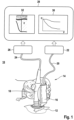
- Fig. 1 shows a measuring system 10 for carrying out ultrasound and pressure measurements on a compartment 12, in particular a muscle compartment 12.
- the measuring system 10 comprises a measuring device 14 known per se with a pressure measuring device 16, which is coupled to an ultrasound measuring unit 18.
- the pressure measuring device 16 is coupled to a pressure evaluation unit 22 via a communication connection 20 and the ultrasound measuring unit 18 is coupled to an image processing unit 26 via a communication connection 24.
- the image processing unit 26 and the pressure evaluation unit 22 are coupled to a data processing unit 28, which is designed to display the data provided by the image processing unit 26 and the pressure evaluation unit on display units 30, 32.
- the method according to the invention is carried out as follows.
- the pressure measuring device 16 is placed together with the ultrasound measuring unit 18, optionally using contact gel in the area of the compartment 12, on a skin surface 34 of the patient.
- a linear transducer from General Electric in combination with an ultrasound-permeable pressure measuring device 16 from VeinPress can be used as the ultrasound measuring unit 18.
- Fig. 2a shows a purely schematic ultrasound image of the compartment 12 at the beginning of a measurement in cross-section.
- an examiner marks image points BP1, BP2 essentially diametrically opposite, preferably on a border 36, such as the compartment skin or fascia, of the compartment 12.
- the image points mark an extension E in the form of an initial extension E0 at the beginning of the examination, ie without compression.
- a force F is then exerted on the tissue, e.g. the skin surface 34 of a lower leg, by means of the pressure measuring device 16.
- the force F is introduced into the compartment 12 in alignment with the image points BP1, BP2 and is continuously increased.
- the force F exerts a continuously increasing pressure P on the compartment 12, which is measured by means of a pressure sensor 38 of the pressure measuring device 16.
- Fig. 2b shows an ultrasound image of the muscle compartment 12 in cross-section during compression, ie when the examiner exerts pressure p on the tissue.
- the extension E (p) changes depending on the pressure p and is continuously recorded by the image processing unit 26. For each measured value of the pressure p, an extension E (p) is measured and displayed as a graph against the pressure p.
- Fig. 3 and 4 show pressure-displacement diagrams 40, in which graphs 42, 44, 50 of measurements on different muscle compartments are shown.
- the internal pressure ICP1, ICP2 is determined from a change ⁇ p of the pressure p acting on the compartment 12 and a change ⁇ E of an extension E(p) of the compartment 12 that occurs during the action of the pressure p.
- the internal pressure is determined as the pressure p at which the change ⁇ E of the extension in the form of a decrease in the extension E(p) due to the change ⁇ p of the pressure p in the form of a preferably defined increase in the pressure p reaches or exceeds a defined threshold value SW for the first time.
- the pressure p and the extension E(p) of the compartment in the direction of the force F are measured simultaneously.
- the change ⁇ E of the extension E(p) at a defined change ⁇ p of the pressure p is determined by comparing the measured extension E(p) with an initial extension E0 according to Fig. 3 or by comparing two consecutive measurements of the extension E(p3) and E(p4) according to Fig. 4 determined, whereby the measured pressure p at which the measured extension E(p) falls below the initial extension E0 or the immediately previously measured extension E(p) for the first time by the threshold value is determined as the internal pressure.
- the defined change ⁇ p in the pressure p at which the change ⁇ E in the extension E is determined is preferably in the range 0 ⁇ ⁇ p ⁇ 10 mmHg.
- the threshold value SW of the decrease in extension is in the range of 0% ⁇ SW ⁇ 10%, preferably in the range of 1% ⁇ SW ⁇ 8%, particularly preferably in the range of 3% ⁇ SW ⁇ 6%, in particular in the range of 4% based on the initial extension E0 or based on a measured value immediately preceding the measured extension.
- Graph 42 shows the special feature that the relative extension Erel (p) in the case of the resting muscle is essentially constant up to a pressure ICP1 and decreases from the pressure ICP1. Investigations have shown that the measured pressure p1 at which the graph 42 first decreases is an internal pressure ICP1 of the muscle compartment, which can also be referred to as an intracompartmental pressure ICP1.
- Graph 44 shows, by way of example, the course of a relative extension Erel (p) of a tense muscle, i.e. of a muscle compartment or a muscle compartment with an increased internal pressure.
- the measured pressure p2 is determined as the internal pressure or intracompartmental pressure ICP2 of the muscle compartment 12 at which the relative extension Erel (p) drops for the first time.
- the extension E (p) determined from the ultrasound image by means of the image processing unit 26 is continuously compared with the initial extension E0.
- the pressure p1, p2 at which the measured extension E (p) falls below the initial extension E0 by at least 4%, preferably 1% to 2%, is determined as the intracompartmental pressure ICP1, ICP2.
- Fig. 4 shows a graph 50 of another measurement, where the graph 50 is S-shaped and a defined drop in the relative extension, as shown in Fig. 3 is not definable. If, for example, the graph 50 shows the course of a circle's circumference in sections, a circle 52 with radius 54 can be adjusted to the graph 50. In this case, the pressure p at which the radius 54 meets the graph 50 in a 45° position relative to the abscissa (horizontal axis - pressure p) can be determined as the internal pressure ICP3.
- the invention is based on the idea that the relative extension or compartment depth does not change initially when pressure is applied. A plateau forms, as can be seen in graphs 42, 44 and 50. When the pressure on the compartment increases, the compartment becomes harder and harder. Only above a certain pressure p1, p2, p3, which corresponds to the intracompartmental pressure ICP1, ICP2, ICP3, does the relative extension Erel decrease.
- the elasticity in the compartment is determined by an elasticity quotient. It was found that the elasticity quotient is subject to high inter-individual fluctuations, which makes interpretation difficult.
- the method according to the invention is distinguished from the methods according to the state of the art in that the determination of an elasticity quotient, i.e. the ratio between the deformation of the healthy tissue in relation to the deformation of the diseased tissue, is not necessary.
- the non-invasive derivation of a pressure value is of medical advantage.
Landscapes
- Health & Medical Sciences (AREA)
- Life Sciences & Earth Sciences (AREA)
- Engineering & Computer Science (AREA)
- Physics & Mathematics (AREA)
- Veterinary Medicine (AREA)
- Biophysics (AREA)
- General Health & Medical Sciences (AREA)
- Pathology (AREA)
- Public Health (AREA)
- Biomedical Technology (AREA)
- Heart & Thoracic Surgery (AREA)
- Medical Informatics (AREA)
- Molecular Biology (AREA)
- Surgery (AREA)
- Animal Behavior & Ethology (AREA)
- Nuclear Medicine, Radiotherapy & Molecular Imaging (AREA)
- Radiology & Medical Imaging (AREA)
- Computer Vision & Pattern Recognition (AREA)
- Dentistry (AREA)
- Oral & Maxillofacial Surgery (AREA)
- Orthopedic Medicine & Surgery (AREA)
- Rheumatology (AREA)
- Physiology (AREA)
- Ultra Sonic Daignosis Equipment (AREA)
- Measuring And Recording Apparatus For Diagnosis (AREA)
Description
- Die Erfindung betrifft ein Verfahren zur Messung eines Innendrucks eines Kompartments, insbesondere eines Muskelkompartments, bei dem eine mit einer Druckmessvorrichtung gekoppelte Ultraschallmesseinheit auf ein Gewebe, unter dem sich das zu messende Kompartment befindet, aufgesetzt und durch Ausübung einer Kraft ein Druck auf das Gewebe gesteigert wird.
- Ein Verfahren der eingangs genannten Art ist aus der
WO2019/106535 A1 bekannt. Bei dem bekannten Verfahren wird eine mit einer Druckmessvorrichtung gekoppelte Ultraschallmesseinheit auf ein Gewebe, unter dem sich das zu messende Kompartment befindet, aufgesetzt, wobei der Druck auf das Gewebe so lange gesteigert wird, bis sich aus der Ultraschallmessung ergibt, dass das Kompartment einen vorbestimmten Verformungsgrad erreicht. Aus einer zu diesem Zeitpunkt vorhandenen Elastizität wird über die Druckmessvorrichtung der Druck in dem Kompartment bestimmt. - Auch der Artikel R. M. Sellei et al: «Assessment of elevated compartment pressures by pressure-related ultrasound: a cadaveric model", European Journal of Trauma and Emergency Surgery, Springer, Berlin/Heidelberg, Bd. 41, Nr. 6, 25. September 2014 beschreibt ebenfalls ein solches Verfahren.
- Die
US 2007/270720 A1 (W. R. Fry ) betrifft ebenfalls die Innendruckbestimmung von I<ompartmenten, z. B. der Zentralvene. Dabei wird das Kompartment mit einem äusseren Druck beaufschlagt, bis es kollabiert. Der notwendige äussere Druck ist dann ein Mass für den Innendruck. - Unter dem Begriff "Kompartment" wird in diesem Zusammenhang ein anatomisch definierter Raum verstanden, der gegenüber der Umgebung abgrenzbar ist. Neben Muskelkompartments stellt beispielsweise auch der Bauchraum ein Kompartment dar.
- Aus der
CH 707046 B1 - Davon ausgehend liegt der vorliegenden Erfindung die Aufgabe zugrunde, ein Verfahren zur Messung eines Innendrucks eines Kompartments derart weiterzubilden, dass eine schnelle und kostengünstige, nichtinvasive Messung des Drucks innerhalb eines Kompartments, insbesondere einer Muskelloge (sogenanntes Logensyndrom) durchgeführt werden kann.
- Die Aufgabe wird erfindungsgemäss u. a. dadurch gelöst, dass der Innendruck aus einer Änderung Δp des auf das Kompartment ein wirkenden Drucks p und einer während der Einwirkung des Drucks p erfolgten Änderung ΔE einer Erstreckung E(p) des Kompartments bestimmt wird.
- Dabei wird der Innendruck als der Druck p bestimmt, bei dem die Änderung ΔE der Erstreckung in Form einer Abnahme der Erstreckung E(p) durch die Änderung Δp des Drucks p in Form einer Erhöhung des Drucks p erstmalig einen definierten Schwellenwert SW erreicht oder überschreitet.
- Mit anderen Worten erfolgt eine Korrelation zwischen der Abnahme der Erstreckung und dem auf das Kompartment einwirkenden Druck p, wobei der Druck p, bei dem die Abnahme einen definierten Schwellwert erreicht oder überschreitet dem Innendruck entspricht.
- Gemäss der Erfindung ist vorgesehen, dass während der Ausübung der Kraft F auf das Gewebe gleichzeitig der Druck p und die in Richtung der Kraft F verlaufende Erstreckung E(p) des Kompartments gemessen wird.
- Die Änderung ΔE der Erstreckung E(p) bei einer definierten Änderung Δp des Drucks p wird durch einen Vergleich der gemessenen Erstreckung E(p) mit einer anfänglichen Erstreckung E0 oder durch einen Vergleich von zwei aufeinanderfolgenden Messwerten der Erstreckung E(p) bestimmt, wobei der gemessene Druck p, bei dem die gemessene Erstreckung E(p) die anfängliche Erstreckung E0 oder die unmittelbar zuvor gemessene Erstreckung E(p) erstmalig um den Schwellenwert unterschreitet, als der Innendruck bestimmt wird.
- Vorzugsweise liegt der Schwellenwert SW der Abnahme der Erstreckung im Bereich von 0% < SW ≤ 10%, vorzugsweise im Bereich von 1% ≤ SW ≤ 8%, besonders bevorzugt im Bereich von 3% ≤ SW ≤ 6%, insbesondere im Bereich von 4% bezogen auf die anfängliche Erstreckung E0 oder bezogen auf einen der gemessenen Erstreckung unmittelbar vorhergehenden Messwert.
- Besonders bevorzugt wird zu Beginn einer Messung, d. h ohne Ausübung einer Kraft F auf das Kompartment, die anfängliche Erstreckung E0 durch Bildpunkte BP1, BP2 in einem Ultraschallbild des Kompartments definiert wird, wobei anschliessend die Kraft F eingeleitet und vorzugsweise kontinuierlich gesteigert wird und wobei die Änderung der Erstreckung E(p) in Abhängigkeit des Drucks p mittels einer Bildverarbeitungseinheit aus den aufgenommenen Ultraschallbildern fortlaufend erfasst wird.
- Vorzugsweise wird die Erstreckung E durch einen Abstand von zumindest zwei Bildpunkten B1, B2 in einem durch die Ultraschallmesseinheit erzeugten Ultraschallbild B des Kompartments definiert. Die Bildpunkte B1, B2 werden vorzugsweise durch einen Anwender auf einer Umrandung, wie Logenhaut, des Kompartments im Wesentlichen diametral gegenüberliegend definiert.
- Die Kraft F wird während einer Messung, vorzugsweise fluchtend mit den Bildpunkten B1, B2 in Richtung der Erstreckung E kontinuierlich erhöht.
- Dabei wird die während der Untersuchungsbewegung sich verändernde Erstreckung E mittels einer Bildverarbeitungseinheit in dem Ultraschallbild B bestimmt und fortlaufend über dem gemessenen Druck p zur Bestimmung des Grafen bzw. Verlaufs aufgetragen.
- Weitere Einzelheiten, Vorteile und Merkmale der Erfindung ergeben sich nicht nur aus den Ansprüchen, den diesen zu entnehmenden Merkmalen - für sich und/oder im Kombination -, sondern auch aus der nachfolgenden Beschreibung von den Zeichnungen zu entnehmenden bevorzugten Ausfiihrungsbeispielen sowie deren Erläuterungen.
- Es zeigen:
- Fig. 1
- eine schematische Darstellung eines Messsystems mit einer Druckmessvorrichtung und einer Ultraschallmesseinheit,
- Fig. 2a
- ein Ultraschallbild eines Muskelkompartments ohne Kompression,
- Fig. 2b
- ein Ultraschallbild eines Muskelkompartments mit Kompression,
- Fig. 3
- ein Druck-Weg-Diagramm mit Grafen einer Untersuchungsbewegung einerseits eines Muskelkompartments in Ruhe und andererseits eines Muskelkompartments in Anspannung, und
- Fig. 4
- ein Druck-Weg-Diagramm mit einem Grafen einer weiteren Untersuchungsbewegung eines Kompartments.
-
Fig. 1 zeigt ein Messsystem 10 zur Durchführung von Ultraschall- und Druckmessungen an einem Kompartment 12, insbesondere einem Muskelkompartment 12. Das Messsystem 10 umfasst eine an sich bekannte Messeinrichtung 14 mit einer Druckmessvorrichtung 16, die mit einer Ultraschallmesseinheit 18 gekoppelt ist. Die Druckmessvorrichtung 16 ist über eine Kommunikationsverbindung 20 mit einer Druckauswerteeinheit 22 gekoppelt und die Ultraschallmesseinheit 18 ist über eine Kommunikationsverbindung 24 mit einer Bildverarbeitungseinheit 26 gekoppelt. - Die Bildverarbeitungseinheit 26 sowie die Druckauswerteeinheit 22 sind mit einer Datenverarbeitungseinheit 28 gekoppelt, die ausgebildet ist, die von der Bildverarbeitungseinheit 26 und der Druckauswerteeinheit bereitgestellten Daten auf Anzeigeeinheiten 30, 32 darzustellen.
- Das erfindungsgemäße Verfahren wird wie folgt durchgeführt. Die Druckmessvorrichtung 16 wird zusammen mit dem Ultraschallmesseinheit 18 ggf. unter Verwendung von Kontaktgel im Bereich des Kompartments 12 auf eine Hautoberfläche 34 des Patienten aufgesetzt. Als Ultraschallmesseinheit 18 kann z. B. ein Linearschallkopf der Firma General Electric in Kombination mit einer Ultraschall durchlässigen Druckmessvorrichtung 16 der Firma VeinPress verwendet werden.
-
Fig. 2a zeigt rein schematisch ein Ultraschallbild des Kompartments 12 zu Beginn einer Messung im Querschnitt. In dem Ultraschallbild werden durch einen Untersucher Bildpunkte BP1, BP2 in Wesentlichen diametral gegenüberliegend vorzugsweise auf einer Umrandung 36, wie Logenhaut oder Faszie, des Kompartments 12 markiert. Durch die Bildpunkte wird eine Erstreckung E in Form einer anfänglichen Erstreckung E0 zu Beginn der Untersuchung markiert, d. h. ohne Kompression. - Mittels der Druckmessvorrichtung 16 wird anschließend eine Kraft F auf das Gewebe, z. B. die Hautoberfläche 34 eines Unterschenkels ausgeübt. Die Kraft F wird fluchtend mit den Bildpunkten BP1, BP2 in das Kompartment 12 eingeleitet und kontinuierlich gesteigert. Durch die Kraft F wird ein kontinuierlich steigender Druck P auf das Kompartment 12 ausgeübt, der mittels eines Drucksensors 38 der Druckmessvorrichtung 16 gemessen wird.
-
Fig. 2b zeigt ein Ultraschallbild des Muskelkompartments 12 im Querschnitt bei Kompression, d.h. dann, wenn durch den Untersucher Druck p auf das Gewebe ausgeübt wird. Die Erstreckung E (p) verändert sich in Abhängigkeit des Drucks p und wird mittels der Bildverarbeitungseinheit 26 fortlaufend erfasst. Zu jedem Messwert des Drucks p wird eine Erstreckung E (p) gemessen und über dem Druck p als Graf dargestellt. -
Fig. 3 und 4 zeigen Druck-Weg-Diagramme 40, in denen Grafen 42, 44, 50 von Messungen an unterschiedlichen Muskelkompartments dargestellt sind. - Gemäß der Erfindung wird der Innendruck ICP1, ICP2 aus einer Änderung Δp des auf das Kompartment 12 einwirkenden Drucks p und einer während der Einwirkung des Drucks p erfolgten Änderung ΔE einer Erstreckung E(p) des Kompartments 12 bestimmt.
- Dabei wird der Innendruck als der Druck p bestimmt, bei dem die Änderung ΔE der Erstreckung in Form einer Abnahme der Erstreckung E(p) durch die Änderung Δp des Drucks p in Form einer vorzugsweise definierten Erhöhung des Drucks p erstmalig einen definierten Schwellenwert SW erreicht oder überschreitet.
- Mit anderen Worten erfolgt eine Korrelation zwischen der Abnahme der Erstreckung und dem auf das Kompartment einwirkenden Druck p, wobei der Druck p, bei dem die Abnahme einen definierten Schwellwert erreicht oder überschreitet dem Innendruck entspricht.
- Gemäß der Erfindung ist vorgesehen, dass während der Ausübung der Kraft F auf das Gewebe gleichzeitig der Druck p und die in Richtung der Kraft F verlaufende Erstreckung E(p) des Kompartments gemessen wird.
- Vorzugsweise wird die Änderung ΔE der Erstreckung E(p) bei einer definierten Änderung Δp des Drucks p durch einen Vergleich der gemessenen Erstreckung E(p) mit einer anfänglichen Erstreckung E0 gemäß
Fig. 3 oder durch einen Vergleich von zwei aufeinanderfolgenden Messwerten der Erstreckung E(p3) und E(p4) gemäßFig. 4 bestimmt, wobei der gemessene Druck p, bei dem die gemessene Erstreckung E(p) die anfängliche Erstreckung E0 oder die unmittelbar zuvor gemessene Erstreckung E(p) erstmalig um den Schwellenwert unterschreitet, als der Innendruck bestimmt wird. Die definierte Änderung Δp des Drucks p, bei der die Änderung ΔE der Erstreckung E ermittelt wird, liegt vorzugsweise im Bereich 0 < Δp ≤ 10 mmHg. - Vorzugsweise liegt der Schwellenwert SW der Abnahme der Erstreckung im Bereich von 0% < SW ≤ 10%, vorzugsweise im Bereich von 1% ≤ SW ≤ 8%, besonders bevorzugt im Bereich von 3% ≤ SW ≤ 6%, insbesondere im Bereich von 4% bezogen auf die anfängliche Erstreckung E0 oder bezogen auf einen der gemessenen Erstreckung unmittelbar vorhergehenden Messwert.
- Der Graf 42 zeigt beispielhaft den Verlauf einer relativen Erstreckung Erel (p) = (E (p) × 100) / E0, die auch als relative Kompartmenttiefe bezeichnet werden kann, über den Kompressionsdruck p eines ruhenden Muskels, d. h. eines Muskelkompartments bzw. einer Muskelloge in Ruhe mit geringem Innendruck. Der Graf 42 zeigt die Besonderheit, dass die relative Erstreckung Erel (p) im Falle des ruhenden Muskels bis zu einem Druck ICP1 im Wesentlichen konstant ist und ab dem Druck ICP1 abfallt. Untersuchungen haben gezeigt, dass der gemessene Druck p1, bei dem der Graf 42 erstmalig abfallt ein Innendruck ICP1 des Muskelkompartments ist, der auch als ein intrakompartimenteller Druck ICP1 bezeichnet werden kann.
- Der Graf 44 zeigt beispielhaft den Verlauf einer relativen Erstreckung Erel (p) eines angespannten Muskels, d. h. eines Muskelkompartments bzw. einer Muskelloge mit einem erhöhten Innendruck. Gemäss einem Aspekt der Erfindung ist vorgesehen, dass der gemessene Druck p2 als der Innendruck bzw. intrakompartimentelle Druck ICP2 des Muskelkompartments 12 bestimmt wird, bei dem die relative Erstreckung Erel (p) erstmalig abfallt.
- Zur Bestimmung der relativen Erstreckung Erel (p) wird die mittels der Bildverarbeitungseinheit 26 aus dem Ultraschallbild ermittelte Erstreckung E (p) kontinuierlich mit der anfänglichen Erstreckung E0 verglichen. Der Druck p1, p2, bei dem die gemessene Erstreckung E (p) die anfängliche Erstreckung E0 um zumindest 4 %, vorzugsweise 1 % bis 2 %, unterschreitet wird als der intrakompartimentelle Druck ICP1, ICP2 bestimmt.
-
Fig. 4 zeigt einen Grafen 50 einer weiteren Messung, wobei der Graf 50 S-förmig verläuft und ein definierter Abfall der relativen Erstreckung, wie dieser inFig. 3 dargestellt ist, nicht definierbar ist. Zeigt der Graf 50 z. B. abschnittsweise den Verlauf eines Kreisumfangs kann ein I<reis 52 mit Radius 54 an den Grafen 50 angepasst werden. In diesem Fall kann der Druck p, bei dem der Radius 54 in 45° Stellung bezogen auf die Abszisse (horizontale Achse - Druck p) den Grafen 50 trifft, als der Innendruck ICP3 bestimmt werden. - Der Erfindung liegt der Gedanke zugrunde, dass sich die relative Erstreckung bzw. Kompartmenttiefe während des Ausübens von Druck zunächst nicht ändert. Es bildet sich ein Plateau, wie an den Grafen 42, 44 und 50 zu erkennen ist. Wenn der Druck auf das Kompartment steigt, wird das Kompartment immer härter. Erst ab einem bestimmten Druck p1, p2, p3, der dem intrakompartimentellen Druck ICP1, ICP2, ICP3 entspricht, fallt die relative Erstreckung Erel ab.
- Nach dem Stand der Technik wird die Elastizität im Kompartment durch einen Elastizitätsquotienten bestimmt. Dabei musste festgestellt werden, dass der Elastizitätsquotient hohen inter-individuellen Schwankungen unterworfen ist, was die Interpretation erschwert. Das erfindungsgemässe Verfahren zeichnet sich gegenüber den Verfahren nach dem Stand der Technik dadurch aus, dass die Bestimmung eines Elastizitätsquotienten, d.h. dass Verhältnis zwischen Verformung des gesunden Gewebes in Bezug zur Verformung des erkrankten Gewebes nicht notwendig ist. Insbesondere ist die nicht-invasive Ableitung eines Druckwertes von medizinischem Vorteil.
Claims (6)
- Verfahren zur Messung eines Innendrucks (ICP1, ICP2) eines Kompartments (12), insbesondere eines Muskelkompartments, bei dem eine mit einer Druckmessvorrichtung (16) gekoppelte Ultraschallmesseinheit (18) auf ein Gewebe (34), unter dem sich das zu messende Kompartment (12) befindet, aufgesetzt und durch Ausübung einer Kraft F ein Druck p auf das Gewebe (12) gesteigert wird,
dadurch gekennzeichnet,dass während der Ausübung der Kraft F auf das Gewebe (34) gleichzeitig der Druck p und die in Richtung der Kraft F verlaufende Erstreckung E(p) des Kompartments (12) gemessen wird, dass eine Änderung ΔE der Erstreckung E(p) bei einer definierten Änderung Δp des Druckes p durch einen Vergleich der gemessenen Erstreckung E(p) mit einer anfänglichen Erstreckung E0 oder durch Vergleich von zwei aufeinanderfolgenden Messwerten der Erstreckung E(p) bestimmt wird unddass der Innendruck (ICP1, ICP2) aus der Änderung Δp des auf das Kompartment (12) einwirkenden Drucks p und der während der Einwirkung des Drucks p erfolgten Änderung ΔE der Erstreckung E(p) des Kompartments (12) bestimmt wird,wobei der Innendruck (ICP1, ICP2) als der Druck p bestimmt wird, bei dem die Änderung ΔE der Erstreckung in Form einer Abnahme der Erstreckung E(p) durch die Änderung Δp des Druckes p in Form einer Erhöhung des Drucks p erstmalig einen definierten Schwellenwert SW erreicht oder überschreitet. - Verfahren nach Anspruch 1,
dadurch gekennzeichnet,
dass der Schwellenwert SW im Bereich von 0% < SW ≤ 10%, vorzugsweise im Bereich von 1% ≤ SW ≤ 8%, besonders bevorzugt im Bereich von 3% ≤ SW ≤ 6%, insbesondere im Bereich von 4% bezogen auf die anfängliche Erstreckung E0 oder bezogen auf einen der gemessenen Erstreckung unmittelbar vorhergehenden Messwert liegt. - Verfahren nach zumindest einem der vorhergehenden Ansprueche,
dadurch gekennzeichnet,
dass zu Beginn einer Messung, d. h. ohne Ausübung einer Kraft F auf das Kompartment, die anfängliche Erstreckung E0 durch Bildpunkte (BP1, BP2) in einem Ultraschallbild des Kompartments (12) definiert wird, dass anschliessend die Kraft F eingeleitet und vorzugsweise kontinuierlich gesteigert wird und dass die Änderung der Erstreckung E(p) in Abhängigkeit des Drucks p mittels einer Bildverarbeitungseinheit (26) aus den Ultraschallbildern fortlaufend erfasst wird. - Verfahren nach Anspruch 3,
dadurch gekennzeichnet,
dass die Bildpunkte (BP1, BP2) auf einer Umrandung, wie Logenhaut, des Kompartments (12) im Wesentlichen diametral gegenüberliegend durch einen Anwender definiert werden. - Verfahren nach Anspruch 3 oder 4,
dadurch gekennzeichnet,
dass die Kraft F während einer Messung, vorzugsweise fluchtend zu einer die Bildpunkte (BP1, BP2) verbindenden Linie, in Richtung der Erstreckung E kontinuierlich erhöht wird. - Verfahren nach Anspruch 3 oder 4,
dadurch gekennzeichnet,
dass die während der Messung sich verändernde Erstreckung E mittels der Bildverarbeitungseinheit (26) in dem Ultraschallbild bestimmt und fortlaufend über dem gemessenen Druck p aufgetragen wird.
Applications Claiming Priority (2)
| Application Number | Priority Date | Filing Date | Title |
|---|---|---|---|
| DE102021109202.7A DE102021109202B3 (de) | 2021-04-13 | 2021-04-13 | Verfahren zur Messung eines Innendrucks eines Kompartments |
| PCT/EP2022/059892 WO2022219051A1 (de) | 2021-04-13 | 2022-04-13 | Verfahren zur messung eines innendrucks eines kompartments |
Publications (3)
| Publication Number | Publication Date |
|---|---|
| EP4322858A1 EP4322858A1 (de) | 2024-02-21 |
| EP4322858C0 EP4322858C0 (de) | 2025-02-12 |
| EP4322858B1 true EP4322858B1 (de) | 2025-02-12 |
Family
ID=81603751
Family Applications (1)
| Application Number | Title | Priority Date | Filing Date |
|---|---|---|---|
| EP22722748.5A Active EP4322858B1 (de) | 2021-04-13 | 2022-04-13 | Verfahren zur messung eines innendrucks eines kompartments |
Country Status (4)
| Country | Link |
|---|---|
| US (1) | US12514559B2 (de) |
| EP (1) | EP4322858B1 (de) |
| DE (1) | DE102021109202B3 (de) |
| WO (1) | WO2022219051A1 (de) |
Family Cites Families (9)
| Publication number | Priority date | Publication date | Assignee | Title |
|---|---|---|---|---|
| DE19754085A1 (de) | 1997-12-05 | 1999-06-10 | Helmut Prof Dr Ing Ermert | Ein sonographisches Elastographiesystem |
| US6086533A (en) | 1998-06-12 | 2000-07-11 | Children's Medical Center Corporation | Non-invasive in vivo pressure measurement |
| US7744535B2 (en) | 2004-07-30 | 2010-06-29 | Wisconsin Alumni Research Foundation | Method and apparatus for acoustoelastic extraction of strain and material properties |
| US7381186B2 (en) | 2004-08-02 | 2008-06-03 | The United States Of America As Represented By The Administrator Of The National Aeronautics And Space Administration | Method and apparatus to assess compartment syndrome |
| US20070270720A1 (en) * | 2006-05-04 | 2007-11-22 | Fry William R | Noninvasive physiologic pressure measurement |
| US9394730B2 (en) | 2009-03-05 | 2016-07-19 | Edmond Rampen | Safety lock |
| CH707046B1 (de) | 2012-09-24 | 2016-05-13 | Veinpress Gmbh | Druckmessvorrichtung zur Kombination mit einer Ultraschallmesseinheit, sowie System und Verfahren zur Venendruckmessung. |
| US10925583B1 (en) | 2017-06-12 | 2021-02-23 | Chesavage Jay A | Apparatus and method for detection of compartment syndrome |
| DE102017221330A1 (de) | 2017-11-28 | 2019-05-29 | Ulrich A. Baumann | Druckmessvorrichtung zur Druckmessung und/oder Elastizitätsmessung einer Vene oder eines Organs und zur Kombination mit einer Ultraschallmesseinheit sowie System und Verfahren zur Druckmessung und/oder Elastizitätsmessung einer Vene oder eines Organs |
-
2021
- 2021-04-13 DE DE102021109202.7A patent/DE102021109202B3/de active Active
-
2022
- 2022-04-13 US US18/555,036 patent/US12514559B2/en active Active
- 2022-04-13 WO PCT/EP2022/059892 patent/WO2022219051A1/de not_active Ceased
- 2022-04-13 EP EP22722748.5A patent/EP4322858B1/de active Active
Also Published As
| Publication number | Publication date |
|---|---|
| EP4322858C0 (de) | 2025-02-12 |
| DE102021109202B3 (de) | 2022-08-18 |
| EP4322858A1 (de) | 2024-02-21 |
| WO2022219051A1 (de) | 2022-10-20 |
| US12514559B2 (en) | 2026-01-06 |
| US20240374239A1 (en) | 2024-11-14 |
| US20250248689A2 (en) | 2025-08-07 |
Similar Documents
| Publication | Publication Date | Title |
|---|---|---|
| DE102017110770B3 (de) | Verfahren zum nicht-invasiven Bestimmen von wenigstens einem Blutdruckwert, Messvorrichtung und System zur nicht-invasiven Blutdruckbestimmung | |
| DE69837392T2 (de) | Verfahren und vorrichtung zur messung des intrakraniellen druckes | |
| EP3716842B1 (de) | Druckmessvorrichtung zur druckmessung und/oder elastizitätsmessung einer vene oder eines organs und zur kombination mit einer ultraschallmesseinheit, druckmesssystem und verfahren | |
| DE112011102420B4 (de) | Messvorrichtung | |
| DE60037854T2 (de) | Berechnung eines Qualitätsindexes für eine Blutdruckmessung | |
| EP2671505B1 (de) | Verfahren und Analysegerät zur Messung einer Hornhaut | |
| DE2436692A1 (de) | Geraet zur messung des blutdrucks od. dgl. in einem menschlichen koerperteil | |
| DE69225713T2 (de) | Vorrichtung zur messung der steifheit von starrem gewebe | |
| DE3200368A1 (de) | Verfahren und vorrichtung zum messen des blutdruckes | |
| DE102010061580A1 (de) | Verwendung des Frequenzspektrums eines Artefaktes in der Oszillometrie | |
| EP2258256B1 (de) | Verfahren zur Bestimmung einer Kontaktlinse | |
| EP2529662B1 (de) | Ophthalmologisches Analyseverfahren und Analysesystem | |
| EP2999402A1 (de) | Messsystem und -verfahren zur messung von parametern in einem körpergewebe | |
| DE112011104312T5 (de) | Blutdruckinformation-Messeinrichtung und Verfahren für das Berechnen des Indexes des Grades der Arteriosklerose mit dieser Einrichtung | |
| DE102004009879A1 (de) | Verfahren und System zum Modifizieren des Manschettendrucks | |
| EP3592216B1 (de) | Verfahren zum betreiben einer blutdruckmessvorrichtung | |
| DE112018001363T5 (de) | Blutdruckmessvorrichtung, verfahren und programm | |
| DE102004009871A1 (de) | Verfahren zur Bestimmung hämodynamischer Parameter | |
| DE102006039957A1 (de) | Verfahren zur Auswertung der Herzratenvariabilität | |
| DE102021109202B3 (de) | Verfahren zur Messung eines Innendrucks eines Kompartments | |
| DE102018125526B4 (de) | Verfahren zur Bestimmung der elastischen Eigenschaften des Myokards | |
| DE112017006598T5 (de) | Prinzip zur Erkennung eines abdominalen Aortenaneurysmas (AAA) aus Impulswellenformen des Arms und Beins | |
| DE102009026016A1 (de) | Verfahren und System zur nichtinvasiven Blutdruckschätzung | |
| EP2710961B1 (de) | Druckmessvorrichtung zur Druckmessung einer Vene oder eines Organs und zur Kombination mit einer Ultraschallmesseinheit, sowie System und Verfahren zur Venen-/Organdruckmessung | |
| EP3773150A1 (de) | Vorrichtung und verfahren zur untersuchung der metabolischen autoregulation |
Legal Events
| Date | Code | Title | Description |
|---|---|---|---|
| STAA | Information on the status of an ep patent application or granted ep patent |
Free format text: STATUS: UNKNOWN |
|
| STAA | Information on the status of an ep patent application or granted ep patent |
Free format text: STATUS: THE INTERNATIONAL PUBLICATION HAS BEEN MADE |
|
| PUAI | Public reference made under article 153(3) epc to a published international application that has entered the european phase |
Free format text: ORIGINAL CODE: 0009012 |
|
| STAA | Information on the status of an ep patent application or granted ep patent |
Free format text: STATUS: REQUEST FOR EXAMINATION WAS MADE |
|
| 17P | Request for examination filed |
Effective date: 20231030 |
|
| AK | Designated contracting states |
Kind code of ref document: A1 Designated state(s): AL AT BE BG CH CY CZ DE DK EE ES FI FR GB GR HR HU IE IS IT LI LT LU LV MC MK MT NL NO PL PT RO RS SE SI SK SM TR |
|
| RAP1 | Party data changed (applicant data changed or rights of an application transferred) |
Owner name: COMPREMIUM AG |
|
| RIN1 | Information on inventor provided before grant (corrected) |
Inventor name: SELLEI, RICHARD MARTIN |
|
| DAV | Request for validation of the european patent (deleted) | ||
| DAX | Request for extension of the european patent (deleted) | ||
| GRAP | Despatch of communication of intention to grant a patent |
Free format text: ORIGINAL CODE: EPIDOSNIGR1 |
|
| STAA | Information on the status of an ep patent application or granted ep patent |
Free format text: STATUS: GRANT OF PATENT IS INTENDED |
|
| INTG | Intention to grant announced |
Effective date: 20240719 |
|
| RIN1 | Information on inventor provided before grant (corrected) |
Inventor name: SELLEI, RICHARD MARTIN |
|
| GRAJ | Information related to disapproval of communication of intention to grant by the applicant or resumption of examination proceedings by the epo deleted |
Free format text: ORIGINAL CODE: EPIDOSDIGR1 |
|
| STAA | Information on the status of an ep patent application or granted ep patent |
Free format text: STATUS: REQUEST FOR EXAMINATION WAS MADE |
|
| INTC | Intention to grant announced (deleted) | ||
| GRAP | Despatch of communication of intention to grant a patent |
Free format text: ORIGINAL CODE: EPIDOSNIGR1 |
|
| STAA | Information on the status of an ep patent application or granted ep patent |
Free format text: STATUS: GRANT OF PATENT IS INTENDED |
|
| INTG | Intention to grant announced |
Effective date: 20241025 |
|
| GRAS | Grant fee paid |
Free format text: ORIGINAL CODE: EPIDOSNIGR3 |
|
| GRAA | (expected) grant |
Free format text: ORIGINAL CODE: 0009210 |
|
| STAA | Information on the status of an ep patent application or granted ep patent |
Free format text: STATUS: THE PATENT HAS BEEN GRANTED |
|
| AK | Designated contracting states |
Kind code of ref document: B1 Designated state(s): AL AT BE BG CH CY CZ DE DK EE ES FI FR GB GR HR HU IE IS IT LI LT LU LV MC MK MT NL NO PL PT RO RS SE SI SK SM TR |
|
| REG | Reference to a national code |
Ref country code: GB Ref legal event code: FG4D Free format text: NOT ENGLISH |
|
| REG | Reference to a national code |
Ref country code: CH Ref legal event code: EP |
|
| REG | Reference to a national code |
Ref country code: DE Ref legal event code: R096 Ref document number: 502022002887 Country of ref document: DE |
|
| REG | Reference to a national code |
Ref country code: IE Ref legal event code: FG4D Free format text: LANGUAGE OF EP DOCUMENT: GERMAN |
|
| U01 | Request for unitary effect filed |
Effective date: 20250214 |
|
| U07 | Unitary effect registered |
Designated state(s): AT BE BG DE DK EE FI FR IT LT LU LV MT NL PT RO SE SI Effective date: 20250220 |
|
| U20 | Renewal fee for the european patent with unitary effect paid |
Year of fee payment: 4 Effective date: 20250425 |
|
| PG25 | Lapsed in a contracting state [announced via postgrant information from national office to epo] |
Ref country code: RS Free format text: LAPSE BECAUSE OF FAILURE TO SUBMIT A TRANSLATION OF THE DESCRIPTION OR TO PAY THE FEE WITHIN THE PRESCRIBED TIME-LIMIT Effective date: 20250512 |
|
| PG25 | Lapsed in a contracting state [announced via postgrant information from national office to epo] |
Ref country code: PL Free format text: LAPSE BECAUSE OF FAILURE TO SUBMIT A TRANSLATION OF THE DESCRIPTION OR TO PAY THE FEE WITHIN THE PRESCRIBED TIME-LIMIT Effective date: 20250212 |
|
| PG25 | Lapsed in a contracting state [announced via postgrant information from national office to epo] |
Ref country code: ES Free format text: LAPSE BECAUSE OF FAILURE TO SUBMIT A TRANSLATION OF THE DESCRIPTION OR TO PAY THE FEE WITHIN THE PRESCRIBED TIME-LIMIT Effective date: 20250212 |
|
| PG25 | Lapsed in a contracting state [announced via postgrant information from national office to epo] |
Ref country code: IS Free format text: LAPSE BECAUSE OF FAILURE TO SUBMIT A TRANSLATION OF THE DESCRIPTION OR TO PAY THE FEE WITHIN THE PRESCRIBED TIME-LIMIT Effective date: 20250612 |
|
| PGFP | Annual fee paid to national office [announced via postgrant information from national office to epo] |
Ref country code: NO Payment date: 20250424 Year of fee payment: 4 |
|
| PG25 | Lapsed in a contracting state [announced via postgrant information from national office to epo] |
Ref country code: HR Free format text: LAPSE BECAUSE OF FAILURE TO SUBMIT A TRANSLATION OF THE DESCRIPTION OR TO PAY THE FEE WITHIN THE PRESCRIBED TIME-LIMIT Effective date: 20250212 |
|
| PG25 | Lapsed in a contracting state [announced via postgrant information from national office to epo] |
Ref country code: GR Free format text: LAPSE BECAUSE OF FAILURE TO SUBMIT A TRANSLATION OF THE DESCRIPTION OR TO PAY THE FEE WITHIN THE PRESCRIBED TIME-LIMIT Effective date: 20250513 |
|
| PGFP | Annual fee paid to national office [announced via postgrant information from national office to epo] |
Ref country code: CH Payment date: 20250501 Year of fee payment: 4 |
|
| PG25 | Lapsed in a contracting state [announced via postgrant information from national office to epo] |
Ref country code: SM Free format text: LAPSE BECAUSE OF FAILURE TO SUBMIT A TRANSLATION OF THE DESCRIPTION OR TO PAY THE FEE WITHIN THE PRESCRIBED TIME-LIMIT Effective date: 20250212 |
|
| PG25 | Lapsed in a contracting state [announced via postgrant information from national office to epo] |
Ref country code: CZ Free format text: LAPSE BECAUSE OF FAILURE TO SUBMIT A TRANSLATION OF THE DESCRIPTION OR TO PAY THE FEE WITHIN THE PRESCRIBED TIME-LIMIT Effective date: 20250212 |
|
| PG25 | Lapsed in a contracting state [announced via postgrant information from national office to epo] |
Ref country code: SK Free format text: LAPSE BECAUSE OF FAILURE TO SUBMIT A TRANSLATION OF THE DESCRIPTION OR TO PAY THE FEE WITHIN THE PRESCRIBED TIME-LIMIT Effective date: 20250212 |
|
| PLBE | No opposition filed within time limit |
Free format text: ORIGINAL CODE: 0009261 |
|
| STAA | Information on the status of an ep patent application or granted ep patent |
Free format text: STATUS: NO OPPOSITION FILED WITHIN TIME LIMIT |
|
| PG25 | Lapsed in a contracting state [announced via postgrant information from national office to epo] |
Ref country code: MC Free format text: LAPSE BECAUSE OF FAILURE TO SUBMIT A TRANSLATION OF THE DESCRIPTION OR TO PAY THE FEE WITHIN THE PRESCRIBED TIME-LIMIT Effective date: 20250212 |
|
| REG | Reference to a national code |
Ref country code: CH Ref legal event code: L10 Free format text: ST27 STATUS EVENT CODE: U-0-0-L10-L00 (AS PROVIDED BY THE NATIONAL OFFICE) Effective date: 20251224 |
|
| 26N | No opposition filed |
Effective date: 20251113 |
|
| PG25 | Lapsed in a contracting state [announced via postgrant information from national office to epo] |
Ref country code: IE Free format text: LAPSE BECAUSE OF NON-PAYMENT OF DUE FEES Effective date: 20250413 |
|
| REG | Reference to a national code |
Ref country code: CH Ref legal event code: U11 Free format text: ST27 STATUS EVENT CODE: U-0-0-U10-U11 (AS PROVIDED BY THE NATIONAL OFFICE) Effective date: 20260501 |