EP4322297A1 - Battery pack having improved shock resistance - Google Patents
Battery pack having improved shock resistance Download PDFInfo
- Publication number
- EP4322297A1 EP4322297A1 EP22895910.2A EP22895910A EP4322297A1 EP 4322297 A1 EP4322297 A1 EP 4322297A1 EP 22895910 A EP22895910 A EP 22895910A EP 4322297 A1 EP4322297 A1 EP 4322297A1
- Authority
- EP
- European Patent Office
- Prior art keywords
- battery pack
- pressing portion
- lower case
- stopper
- module frame
- Prior art date
- Legal status (The legal status is an assumption and is not a legal conclusion. Google has not performed a legal analysis and makes no representation as to the accuracy of the status listed.)
- Granted
Links
Images




Classifications
-
- H—ELECTRICITY
- H01—ELECTRIC ELEMENTS
- H01M—PROCESSES OR MEANS, e.g. BATTERIES, FOR THE DIRECT CONVERSION OF CHEMICAL ENERGY INTO ELECTRICAL ENERGY
- H01M50/00—Constructional details or processes of manufacture of the non-active parts of electrochemical cells other than fuel cells, e.g. hybrid cells
- H01M50/20—Mountings; Secondary casings or frames; Racks, modules or packs; Suspension devices; Shock absorbers; Transport or carrying devices; Holders
- H01M50/204—Racks, modules or packs for multiple batteries or multiple cells
-
- H—ELECTRICITY
- H01—ELECTRIC ELEMENTS
- H01M—PROCESSES OR MEANS, e.g. BATTERIES, FOR THE DIRECT CONVERSION OF CHEMICAL ENERGY INTO ELECTRICAL ENERGY
- H01M50/00—Constructional details or processes of manufacture of the non-active parts of electrochemical cells other than fuel cells, e.g. hybrid cells
- H01M50/20—Mountings; Secondary casings or frames; Racks, modules or packs; Suspension devices; Shock absorbers; Transport or carrying devices; Holders
- H01M50/233—Mountings; Secondary casings or frames; Racks, modules or packs; Suspension devices; Shock absorbers; Transport or carrying devices; Holders characterised by physical properties of casings or racks, e.g. dimensions
- H01M50/242—Mountings; Secondary casings or frames; Racks, modules or packs; Suspension devices; Shock absorbers; Transport or carrying devices; Holders characterised by physical properties of casings or racks, e.g. dimensions adapted for protecting batteries against vibrations, collision impact or swelling
-
- H—ELECTRICITY
- H01—ELECTRIC ELEMENTS
- H01M—PROCESSES OR MEANS, e.g. BATTERIES, FOR THE DIRECT CONVERSION OF CHEMICAL ENERGY INTO ELECTRICAL ENERGY
- H01M50/00—Constructional details or processes of manufacture of the non-active parts of electrochemical cells other than fuel cells, e.g. hybrid cells
- H01M50/20—Mountings; Secondary casings or frames; Racks, modules or packs; Suspension devices; Shock absorbers; Transport or carrying devices; Holders
- H01M50/202—Casings or frames around the primary casing of a single cell or a single battery
-
- H—ELECTRICITY
- H01—ELECTRIC ELEMENTS
- H01M—PROCESSES OR MEANS, e.g. BATTERIES, FOR THE DIRECT CONVERSION OF CHEMICAL ENERGY INTO ELECTRICAL ENERGY
- H01M50/00—Constructional details or processes of manufacture of the non-active parts of electrochemical cells other than fuel cells, e.g. hybrid cells
- H01M50/20—Mountings; Secondary casings or frames; Racks, modules or packs; Suspension devices; Shock absorbers; Transport or carrying devices; Holders
- H01M50/244—Secondary casings; Racks; Suspension devices; Carrying devices; Holders characterised by their mounting method
-
- H—ELECTRICITY
- H01—ELECTRIC ELEMENTS
- H01M—PROCESSES OR MEANS, e.g. BATTERIES, FOR THE DIRECT CONVERSION OF CHEMICAL ENERGY INTO ELECTRICAL ENERGY
- H01M50/00—Constructional details or processes of manufacture of the non-active parts of electrochemical cells other than fuel cells, e.g. hybrid cells
- H01M50/20—Mountings; Secondary casings or frames; Racks, modules or packs; Suspension devices; Shock absorbers; Transport or carrying devices; Holders
- H01M50/204—Racks, modules or packs for multiple batteries or multiple cells
- H01M50/207—Racks, modules or packs for multiple batteries or multiple cells characterised by their shape
- H01M50/213—Racks, modules or packs for multiple batteries or multiple cells characterised by their shape adapted for cells having curved cross-section, e.g. round or elliptic
-
- Y—GENERAL TAGGING OF NEW TECHNOLOGICAL DEVELOPMENTS; GENERAL TAGGING OF CROSS-SECTIONAL TECHNOLOGIES SPANNING OVER SEVERAL SECTIONS OF THE IPC; TECHNICAL SUBJECTS COVERED BY FORMER USPC CROSS-REFERENCE ART COLLECTIONS [XRACs] AND DIGESTS
- Y02—TECHNOLOGIES OR APPLICATIONS FOR MITIGATION OR ADAPTATION AGAINST CLIMATE CHANGE
- Y02E—REDUCTION OF GREENHOUSE GAS [GHG] EMISSIONS, RELATED TO ENERGY GENERATION, TRANSMISSION OR DISTRIBUTION
- Y02E60/00—Enabling technologies; Technologies with a potential or indirect contribution to GHG emissions mitigation
- Y02E60/10—Energy storage using batteries
Definitions
- the present invention relates to a battery pack having improved impact resistance, and more particularly to a battery pack having improved impact resistance configured such that a battery module is protected from internal vibration or impact and the battery pack is easily assembled.
- Secondary batteries which are capable of being charged and discharged, are widely used in various fields, such as mobile devices, electric vehicles, hybrid electric vehicles, and industrial robots.
- a battery pack includes a battery pack case in order to package battery modules, and the battery modules are fixed in the battery pack case in order to prevent vibration or impact.
- the battery modules are generally fixed in the battery pack case through a separate structure, such as a bolt and nut.
- Patent Document 1 Korean Registered Patent Publication No. 2167632 (published on October 19, 2020 )
- the present invention has been made in view of the above problems, and it is an object of the present invention to provide a battery pack having improved impact resistance configured such that an impact attenuation member is provided in a space between a battery module and the battery pack.
- a battery pack according to the present invention includes a lower case (100) provided with a space having a predetermined size, an upper case (200) located at an upper part of the lower case (100) to be fastened to the lower case, at least one module frame (300) received in the space of the lower case (100) and a space of the upper case (200), the module frame being provided with a battery cell receiving recess (310), and a battery cell received in the battery cell receiving recess (310), wherein an impact attenuation member configured to protect the module frame (300) from external impact is disposed between an outer surface of the module frame (300) and an inner surface of the lower case (100).
- the impact attenuation member may include a first stopper (400), and the first stopper (400) may include a first pressing portion (410) having a column shape in contact with the outer surface of the module frame (300) and a pair of wings (420) extending from opposite sides of the first pressing portion (410) by a predetermined length.
- a first receiving portion (110) configured to fix the first stopper (400) may be disposed in a side wall of the lower case (100), and the first receiving portion (110) may include a receiving recess (111) configured to encompass a rear surface and a side surface of each wing (420) such that the wing is seated and fixed, a horizontal support projection (112) configured to support a bottom surface of the wing (420), a pair of vertical support projections (113) configured to support a part of a front surface of the wing (420), and an opening (114) between the pair of vertical support projections (113) such that the first pressing portion (410) protrudes forwards by a predetermined length.
- a front middle part of the first pressing portion (410) may protrude farther forwards than front upper and lower parts of the first pressing portion in a height direction.
- a rear middle part of the first pressing portion (410) may protrude farther rearwards than rear upper and lower parts of the first pressing portion in the height direction.
- the impact attenuation member may include a second stopper (500), and the second stopper (500) may include a second pressing portion (510) having a column shape, the second pressing portion (510) having one side in contact with the outer surface of the module frame (300) and the other side in contact with the inner surface of the lower case (100), a head portion (520) having one surface in contact with an outer surface of the lower case (100), and a connection portion (530) configured to connect the second pressing portion (510) and the head portion (520) to each other.
- the second stopper (500) may include a second pressing portion (510) having a column shape, the second pressing portion (510) having one side in contact with the outer surface of the module frame (300) and the other side in contact with the inner surface of the lower case (100), a head portion (520) having one surface in contact with an outer surface of the lower case (100), and a connection portion (530) configured to connect the second pressing portion (510) and the head portion (520) to each other.
- a second receiving portion (120) configured to fix the second stopper (500) may be in a side wall of the lower case (100), and the second receiving portion (120) may include a through-hole (121) configured to allow the connection portion (530) to be disposed therein, an outer support projection (122) formed at the outer surface of the lower case (100), the outer support projection being configured to support the head portion (520), and an inner support projection (123) formed at the inner surface of the lower case (100), the inner support projection being configured to support a part of the second pressing portion (510).
- each of the second pressing portion (510), the head portion (520), and the connection portion (530) may be cylindrical, the diameter of the connection portion (530) may be less than the diameter of each of the second pressing portion (510) and the head portion (520), and the diameter of the through-hole (121) may be less than the diameter of each of the second pressing portion (510) and the head portion (520).
- the diameter of the head portion (520) may be greater than the diameter of the second pressing portion (510).
- a depressed portion (511) may be disposed in one end of the second pressing portion (510) to form a predetermined space.
- the present invention provides a device having the battery pack mounted therein.
- a battery pack having improved impact resistance has an advantage in that a first stopper constituted by a first pressing portion having a column shape made of an elastic material and a pair of wings is interposed between an outer surface of a module frame and an inner surface of a case, whereby it is possible to protect a battery module from external impact or vibration.
- the battery pack having improved impact resistance according to the present invention has an advantage in that a second stopper constituted by a second pressing portion having a column shape made of an elastic material, a head portion, and a connection portion is interposed between the outer surface of the module frame and the inner surface of the case, whereby it is possible to protect the battery module from external impact or vibration.
- the battery pack having improved impact resistance according to the present invention has a merit in that a receiving portion integrally formed with the case is provided, whereby it is possible to stably receive and fix the first stopper and the second stopper.
- the battery pack having improved impact resistance according to the present invention has an advantage in that the first stopper and the second stopper are easily mounted in the case, whereby it is possible to achieve easy assembly.
- FIG. 1 is a perspective view of a battery pack according to a preferred embodiment of the present invention
- FIG. 2 is a plan view showing the interior of the battery pack shown in FIG. 1 .
- the battery pack according to the present invention includes a lower case 100, an upper case 200, a module frame 300, and a first stopper 400 and a second stopper 500 constituting an impact attenuation member.
- the lower case 100 has a structure in which the lower case is surrounded by predetermined walls in the drawings, the present invention is not limited thereto, and the lower case may be replaced with a cover having no separate space.
- module frames 300 are shown as being mounted, which, however, is merely an example, the number of the module frames may be increased or decreased.
- first stoppers 400 are shown as being located at the front and the rear (an upper part and a lower part in the drawings) of the leftmost module frame 300 and a pair of second stoppers 500 are shown as being located at the front and the rear of the rightmost module frame 300, it is obvious that a pair of stoppers may be located at the front and the rear of each module frame.
- first stoppers 400 may be mounted at the front and the rear of each module frame 300, or the second stoppers 500 may be mounted at the front and the rear of each module frame 300.
- stoppers may be further provided at sides of module frames 300 disposed adjacent to side walls of the lower case 100, in addition to the front and the rear thereof.
- the first stopper 400 and the second stopper 500 attenuate impact to protect a battery module having a battery cell received therein.
- the lower case 100 has a space sufficient to receive the module frame 300, and is surrounded by side walls such that the battery module is primarily protected from external impact.
- the upper case 200 may be seated on the lower case 100, and the cases may be fixed to each other via a known fastening means, such as a long bolt.
- FIG. 3 is an enlarged view showing part A of FIG. 2
- FIG. 4 is a perspective view of the first stopper mounted in the battery pack according to the preferred embodiment of the present invention
- FIG. 5 is an enlarged view of a first receiving portion configured to receive the first stopper in part A of FIG. 3
- FIG. 6 is a perspective view of the module frame mounted in the battery pack according to the preferred embodiment of the present invention.
- the first stopper of the present invention will be described in detail with reference to FIGs. 3 to 6 .
- the first stopper 400 includes a first pressing portion 410 having a column shape brought into tight contact with a pressure surface 320 of the module frame 300, which is an outer surface, and a pair of wings 420 extending from opposite sides of the first pressing portion 410 by a predetermined length.
- the first stopper 400 when viewed from above, has a shape similar to an approximately "T" shape.
- the front part of the first pressing portion 410 i.e. the part of the first pressing portion brought into tight contact with the pressure surface 320 of the module frame 300, to somewhat protrude toward the front (X-axis direction) in order to increase pressing force, e.g. to be somewhat rounded in a circumferential direction.
- front and rear middle parts of the first pressing portion 410 to slightly protrude in a height direction (Y-axis direction). Specifically, the front middle part of the first pressing portion 410 protrudes farther forwards than front upper and lower parts thereof, and the rear middle part of the first pressing portion protrudes farther rearwards than rear upper and lower parts thereof.
- the reason for this is that it is possible to fix the module frame 300 in a tight contact state with stronger force, as previously described, and to prevent separation of the first stopper 400 from a first receiving portion provided in the side wall of the lower case 100, a description of which will follow, after the first stopper is received in the first receiving portion.
- the front and rear middle parts of the first pressing portion 410 protrude slightly more than the front and rear lower parts thereof, it is possible to easily mount the first stopper in the first receiving portion provided in the side wall of the lower case 100.
- a first inclined surface 411 slightly inclined forwards is provided on an upper surface of the first pressing portion 410. The reason for this is that it is possible to easily insert the module frame 300 to be mounted into the lower case 100 along the first inclined surface 411.
- the first receiving portion 110 configured to fix the first stopper 400 is formed in the side wall of the lower case 100, i.e. the part of the lower case 100 that faces the pressure surface 320 of the module frame 300.
- the first receiving portion 110 is constituted by a receiving recess 111, a horizontal support projection 112, a pair of vertical support projections 113, and an opening 114.
- the receiving recess 111 which is formed so as to receive a part of the first pressing portion 410 and the wing 420 of the first stopper 400, has an approximately rectangular structure when viewed from above, and is brought into tight contact with a rear surface of the first pressing portion 410 and a part of the wing 420.
- the horizontal support projection 112 supports a bottom surface of the wing 420 such that the first stopper 400 cannot moved downwards, and the pair of vertical support projections 113 blocks a part of a front surface of the wing 420 such that the first receiving portion 110 is not separated forwards.
- the opening 114 is provided between the pair of vertical support projections 113, and the first pressing portion 410 protrudes forwards by a predetermined length through the opening 114, whereby the first pressing portion 410 presses the pressure surface 320 of the module frame 300.
- a bolt fastening recess 330 configured to primarily fix the lower case 100 and the module frame 300 is provided under a side surface of the module frame 300, as shown in FIG. 6 .
- the module frame 300 is received in the lower case 100, the lower case 100 and the module frame 300 are fixed to each other using a bolt 340, and the first stopper 400 is mounted in the first receiving portion 110.
- first pressing portion 410 must have a length sufficient to securely press the pressure surface 320 of the module frame 300 when the first stopper 400 is mounted in the first receiving portion 110.
- the material for the first stopper 400 is not particularly restricted as long as the material exhibits predetermined elasticity.
- silicone may be used.
- a battery cell is received in a battery cell receiving recess 310 of the module frame 300.
- the cylindrical battery cell generally includes an electrode assembly, an insulation member, a positive electrode lead wire, a cap assembly, and a battery can configured to receive the above components.
- the electrode assembly may be a jelly-roll type electrode assembly, which is configured to have a structure in which a long sheet type positive electrode and a long sheet type negative electrode are wound in the state in which a separator is interposed therebetween, a stacked type electrode assembly including unit cells, each of which is configured to have a structure in which a rectangular positive electrode and a rectangular negative electrode are stacked in the state in which a separator is interposed therebetween, a stacked and folded type electrode assembly, which is configured to have a structure in which unit cells are wound using a long separation film, or a laminated and stacked type electrode assembly, which is configured to have a structure in which unit cells are stacked in the state in which a separator is interposed therebetween and are then attached to each other.
- the positive electrode lead wire which is attached to an upper end of the electrode assembly, is electrically connected to the cap assembly
- a negative electrode lead wire which is attached to a lower end of the electrode assembly
- the insulation member may be located at an upper part of the electrode assembly, and the insulation member serves to insulate between the electrode assembly and the cap assembly.
- the cap assembly is located at an upper part of the insulation member so as to be electrically connected to the positive electrode lead wire attached to the upper end of the electrode assembly, and is coupled to an open end of an upper part of the battery can to hermetically seal the electrode assembly received in the battery can.
- the cap assembly may be configured such that a current cut-off member, a current cut-off gasket, a safety vent, and a top cap are sequentially stacked from the bottom, and a crimping gasket and a welding holder may be located at outer edges of the safety vent and the top cap.
- FIG. 7 is an enlarged view showing part B of FIG. 2
- FIG. 8 is a front perspective view of the second stopper mounted in the battery pack according to the preferred embodiment of the present invention
- FIG. 9 is a bottom perspective view of the second stopper shown in FIG. 8 .
- the second stopper 500 will be described with reference to FIGs. 7 to 9 .
- the second stopper 500 includes a second pressing portion 510 having a column shape, a head portion 520, and a connection portion 530.
- the second pressing portion 510 it is preferable for the second pressing portion 510 to have a cylindrical shape having a structure in which an end of the second pressing portion is somewhat curved while the second pressing portion has a predetermined diameter such that one side of the second pressing portion is brought into tight contact with the pressure surface 320 of the module frame 300 and the other side of the second pressing portion is brought into tight contact with an inner surface of the lower case 100.
- a depressed portion 511 dented inwards it is preferable for a depressed portion 511 dented inwards to be provided in one end of the second pressing portion 510, i.e. the part of the second pressing portion brought into tight contact with the pressure surface 320 of the module frame 300, so as to form a predetermined space.
- the reason for this is that it is possible to further attenuate impact by the empty space formed by the depressed portion 511.
- the head portion 520 is located at an outer surface of the lower case 100, and an inner surface of the head portion 520 may be brought into tight contact with the outer surface of the lower case 100.
- the head portion may be formed in a circular shape having a predetermined thickness.
- the connection portion 530 is configured to connect the second pressing portion 510 and the head portion 520 to each other.
- FIG. 10 is a perspective view of a second receiving portion in which the second stopper is mounted when viewed from the outside of the lower case
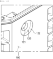
- FIG. 11 is a perspective view of the second receiving portion in which the second stopper is mounted when viewed from the inside of the lower case
- FIG. 12 is a perspective view illustrating the state in which the second stopper is mounted to part B of FIG. 2 .
- the second receiving portion 120 configured to fix the second stopper 500 will be described with reference to FIGs. 10 to 12 .
- the second receiving portion 120 configured to fix the second stopper 500 is provided in the side wall of the lower case 100, i.e. the part of the lower case that faces the pressure surface 320 of the module frame 300.
- the second receiving portion 120 is constituted by a through-hole 121, an outer support projection 122, and an inner support projection 123.
- the through-hole 121 which is the part at which the connection portion 530 is located, has a diameter slightly less than the diameter of the connection portion 530 such that the connection portion 530 can be securely supported and moisture cannot be introduced, and the head portion 520 is supported by the outer support projection 122.
- the outer support projection 122 it is preferable for the outer support projection 122 to be slightly depressed inwardly of the side wall so as not to protrude out of the outer surface of the lower case 100 when the head portion 520 is located, and it is preferable for the outer support projection to have a diameter slightly greater than the diameter of the head portion 520 while having a circular shape corresponding to the outer shape of the head portion 520.
- the inner support projection 123 is slightly depressed so as to support a part of the second pressing portion 510, i.e. the vicinity of the connection portion 530, and it is more preferable for the inner support projection 123 to have a diameter slightly greater than the diameter of the connection portion 530 while having a circular shape identical to the outer shape of the connection portion 530.
- the diameter of the head portion 520 be the largest and that the diameter be smaller in the order of the second pressing portion 510 and the connection portion 530. The reason for this is that it is possible to easily mount the second stopper 500 in the second receiving portion 120 and to prevent the second stopper 500 from being easily separated from the second receiving portion 120.
- the second pressing portion 510 must have a length sufficient to securely press the pressure surface 320 of the module frame 300 when the second stopper 500 is mounted in the second receiving portion 120.
- the module frame 300 is received in the lower case 100, the lower case 100 and the module frame 300 are fixed to each other using a bolt B, and the second stopper 500 is mounted in the second receiving portion 120, as described in connection with the first receiving portion 110.
- the second pressing portion 510 is pushed from the outer surface to the inner surface of the lower case 100 until the second pressing portion extends through the through-hole 121 and reaches the inner support projection 123.
- the second stopper 500 may be made of the same material as the first stopper 400.
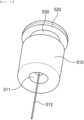
- FIG. 13 is a perspective view of the second stopper before being mounted in the battery pack when viewed from below.
- the second stopper 500 shown in FIG. 13 is identical in construction to the second stopper described above except that a grip bar 512 having one side connected to the depressed portion 511 and extending long while having a diameter less than the diameter of the through-hole 121 is further provided.
- the grip bar 512 may assist in more convenient assembly of the second stopper 500. Specifically, the grip bar 512 is inserted through the through-hole 121, and the head portion 520 is pushed in while pulling the grip bar 512 with one hand. Of course, a part of the grip bar 512 may be cut after assembly of the second stopper 500 in the second receiving portion 120.
- the battery pack may be used as a power source for various kinds of devices.
Landscapes
- Chemical & Material Sciences (AREA)
- Chemical Kinetics & Catalysis (AREA)
- Electrochemistry (AREA)
- General Chemical & Material Sciences (AREA)
- Battery Mounting, Suspending (AREA)
Abstract
Description
- This application claims the benefit of priority to
Korean Patent Application No. 2021-0157889 filed on November 16, 2021 - The present invention relates to a battery pack having improved impact resistance, and more particularly to a battery pack having improved impact resistance configured such that a battery module is protected from internal vibration or impact and the battery pack is easily assembled.
- With recent development of alternative energies due to air pollution and energy depletion caused as the result of use of fossil fuels, demand for secondary batteries capable of storing electrical energy that is produced has increased. Secondary batteries, which are capable of being charged and discharged, are widely used in various fields, such as mobile devices, electric vehicles, hybrid electric vehicles, and industrial robots.
- Required capacities of secondary batteries used as energy sources of various kinds of electronic devices inevitably used in modern society have been increased due to an increase in usage of mobile devices, increasing complexity of the mobile devices, and development of electric vehicles. In order to satisfy demand of users, a plurality of battery cells is disposed in a small-sized device, whereas a battery module including a plurality of battery cells electrically connected to each other or a battery pack including a plurality of battery modules is used in a vehicle.
- Meanwhile, a battery pack includes a battery pack case in order to package battery modules, and the battery modules are fixed in the battery pack case in order to prevent vibration or impact. In a conventional battery pack, the battery modules are generally fixed in the battery pack case through a separate structure, such as a bolt and nut.
- However, it is impossible to completely protect the battery modules from external impact using only a known fastening means, such as a bolt and nut, and when a large number of bolts and nuts are used, the size of the battery pack is increased, since a fastening space is necessary.
- (Patent Document 1)
Korean Registered Patent Publication No. 2167632 (published on October 19, 2020 - The present invention has been made in view of the above problems, and it is an object of the present invention to provide a battery pack having improved impact resistance configured such that an impact attenuation member is provided in a space between a battery module and the battery pack.
- It is another object of the present invention to provide a battery pack having improved impact resistance configured to have a structure in which the size of the battery pack is not increased and the battery pack is easily assembled.
- In order to accomplish the above objects, a battery pack according to the present invention includes a lower case (100) provided with a space having a predetermined size, an upper case (200) located at an upper part of the lower case (100) to be fastened to the lower case, at least one module frame (300) received in the space of the lower case (100) and a space of the upper case (200), the module frame being provided with a battery cell receiving recess (310), and a battery cell received in the battery cell receiving recess (310), wherein an impact attenuation member configured to protect the module frame (300) from external impact is disposed between an outer surface of the module frame (300) and an inner surface of the lower case (100).
- Also, in the battery pack according to the present invention, the impact attenuation member may include a first stopper (400), and the first stopper (400) may include a first pressing portion (410) having a column shape in contact with the outer surface of the module frame (300) and a pair of wings (420) extending from opposite sides of the first pressing portion (410) by a predetermined length.
- Also, in the battery pack according to the present invention, a first receiving portion (110) configured to fix the first stopper (400) may be disposed in a side wall of the lower case (100), and the first receiving portion (110) may include a receiving recess (111) configured to encompass a rear surface and a side surface of each wing (420) such that the wing is seated and fixed, a horizontal support projection (112) configured to support a bottom surface of the wing (420), a pair of vertical support projections (113) configured to support a part of a front surface of the wing (420), and an opening (114) between the pair of vertical support projections (113) such that the first pressing portion (410) protrudes forwards by a predetermined length.
- Also, in the battery pack according to the present invention, a front middle part of the first pressing portion (410) may protrude farther forwards than front upper and lower parts of the first pressing portion in a height direction.
- Also, in the battery pack according to the present invention, a rear middle part of the first pressing portion (410) may protrude farther rearwards than rear upper and lower parts of the first pressing portion in the height direction.
- Also, in the battery pack according to the present invention, the impact attenuation member may include a second stopper (500), and the second stopper (500) may include a second pressing portion (510) having a column shape, the second pressing portion (510) having one side in contact with the outer surface of the module frame (300) and the other side in contact with the inner surface of the lower case (100), a head portion (520) having one surface in contact with an outer surface of the lower case (100), and a connection portion (530) configured to connect the second pressing portion (510) and the head portion (520) to each other.
- Also, in the battery pack according to the present invention, a second receiving portion (120) configured to fix the second stopper (500) may be in a side wall of the lower case (100), and the second receiving portion (120) may include a through-hole (121) configured to allow the connection portion (530) to be disposed therein, an outer support projection (122) formed at the outer surface of the lower case (100), the outer support projection being configured to support the head portion (520), and an inner support projection (123) formed at the inner surface of the lower case (100), the inner support projection being configured to support a part of the second pressing portion (510).
- Also, in the battery pack according to the present invention, each of the second pressing portion (510), the head portion (520), and the connection portion (530) may be cylindrical, the diameter of the connection portion (530) may be less than the diameter of each of the second pressing portion (510) and the head portion (520), and the diameter of the through-hole (121) may be less than the diameter of each of the second pressing portion (510) and the head portion (520).
- Also, in the battery pack according to the present invention, the diameter of the head portion (520) may be greater than the diameter of the second pressing portion (510).
- Also, in the battery pack according to the present invention, a depressed portion (511) may be disposed in one end of the second pressing portion (510) to form a predetermined space.
- In addition, the present invention provides a device having the battery pack mounted therein.
- As is apparent from the above description, a battery pack having improved impact resistance according to the present invention has an advantage in that a first stopper constituted by a first pressing portion having a column shape made of an elastic material and a pair of wings is interposed between an outer surface of a module frame and an inner surface of a case, whereby it is possible to protect a battery module from external impact or vibration.
- In addition, the battery pack having improved impact resistance according to the present invention has an advantage in that a second stopper constituted by a second pressing portion having a column shape made of an elastic material, a head portion, and a connection portion is interposed between the outer surface of the module frame and the inner surface of the case, whereby it is possible to protect the battery module from external impact or vibration.
- In addition, the battery pack having improved impact resistance according to the present invention has a merit in that a receiving portion integrally formed with the case is provided, whereby it is possible to stably receive and fix the first stopper and the second stopper.
- Furthermore, the battery pack having improved impact resistance according to the present invention has an advantage in that the first stopper and the second stopper are easily mounted in the case, whereby it is possible to achieve easy assembly.
-
-
FIG. 1 is a perspective view of a battery pack according to a preferred embodiment of the present invention. -
FIG. 2 is a plan view showing the interior of the battery pack shown inFIG. 1 . -
FIG. 3 is an enlarged view showing part A ofFIG. 2 . -
FIG. 4 is a perspective view of a first stopper mounted in the battery pack according to the preferred embodiment of the present invention. -
FIG. 5 is an enlarged view of a first receiving portion configured to receive the first stopper in part A ofFIG. 3 . -
FIG. 6 is a perspective view of a module frame mounted in the battery pack according to the preferred embodiment of the present invention. -
FIG. 7 is an enlarged view showing part B ofFIG. 2 . -
FIG. 8 is a front perspective view of a second stopper mounted in the battery pack according to the preferred embodiment of the present invention. -
FIG. 9 is a bottom perspective view of the second stopper shown inFIG. 8 . -
FIG. 10 is a perspective view of a second receiving portion in which the second stopper is mounted when viewed from the outside of a lower case. -
FIG. 11 is a perspective view of the second receiving portion in which the second stopper is mounted when viewed from the inside of the lower case. -
FIG. 12 is a perspective view illustrating the state in which the second stopper is mounted to part B ofFIG. 2 . -
FIG. 13 is a perspective view of the second stopper before being mounted in the battery pack when viewed from below. - Now, preferred embodiments of the present invention will be described in detail with reference to the accompanying drawings such that the preferred embodiments of the present invention can be easily implemented by a person having ordinary skill in the art to which the present invention pertains. In describing the principle of operation of the preferred embodiments of the present invention in detail, however, a detailed description of known functions and configurations incorporated herein will be omitted when the same may obscure the subject matter of the present invention.
- In addition, the same reference numbers will be used throughout the drawings to refer to parts that perform similar functions or operations. In the case in which one part is said to be connected to another part in the entire specification, not only may the one part be directly connected to the other part, but also, the one part may be indirectly connected to the other part via a further part. In addition, that a certain element is included does not mean that other elements are excluded, but means that such elements may be further included unless mentioned otherwise.
- Hereinafter, a battery pack having an impact attenuation member according to the present invention will be described with reference to the accompanying drawings.
-
FIG. 1 is a perspective view of a battery pack according to a preferred embodiment of the present invention, andFIG. 2 is a plan view showing the interior of the battery pack shown inFIG. 1 . - Referring to
FIGs. 1 and2 , the battery pack according to the present invention includes alower case 100, anupper case 200, amodule frame 300, and afirst stopper 400 and asecond stopper 500 constituting an impact attenuation member. - Although the
lower case 100 has a structure in which the lower case is surrounded by predetermined walls in the drawings, the present invention is not limited thereto, and the lower case may be replaced with a cover having no separate space. - In addition, although four
module frames 300 are shown as being mounted, which, however, is merely an example, the number of the module frames may be increased or decreased. - In addition, although a pair of
first stoppers 400 are shown as being located at the front and the rear (an upper part and a lower part in the drawings) of theleftmost module frame 300 and a pair ofsecond stoppers 500 are shown as being located at the front and the rear of therightmost module frame 300, it is obvious that a pair of stoppers may be located at the front and the rear of each module frame. - In addition, only the
first stoppers 400 may be mounted at the front and the rear of eachmodule frame 300, or thesecond stoppers 500 may be mounted at the front and the rear of eachmodule frame 300. - Furthermore, stoppers may be further provided at sides of
module frames 300 disposed adjacent to side walls of thelower case 100, in addition to the front and the rear thereof. - When the battery pack is abnormal, for example when external impact is applied to the battery pack or when the battery pack drops, the
first stopper 400 and the second stopper 500 attenuate impact to protect a battery module having a battery cell received therein. - The
lower case 100 has a space sufficient to receive themodule frame 300, and is surrounded by side walls such that the battery module is primarily protected from external impact. Theupper case 200 may be seated on thelower case 100, and the cases may be fixed to each other via a known fastening means, such as a long bolt. -
FIG. 3 is an enlarged view showing part A ofFIG. 2 ,FIG. 4 is a perspective view of the first stopper mounted in the battery pack according to the preferred embodiment of the present invention,FIG. 5 is an enlarged view of a first receiving portion configured to receive the first stopper in part A ofFIG. 3 , andFIG. 6 is a perspective view of the module frame mounted in the battery pack according to the preferred embodiment of the present invention. - The first stopper of the present invention will be described in detail with reference to
FIGs. 3 to 6 . - The
first stopper 400 includes a firstpressing portion 410 having a column shape brought into tight contact with apressure surface 320 of themodule frame 300, which is an outer surface, and a pair ofwings 420 extending from opposite sides of the firstpressing portion 410 by a predetermined length. - Specifically, when viewed from above, the
first stopper 400 has a shape similar to an approximately "T" shape. Here, it is preferable for the front part of the firstpressing portion 410, i.e. the part of the first pressing portion brought into tight contact with thepressure surface 320 of themodule frame 300, to somewhat protrude toward the front (X-axis direction) in order to increase pressing force, e.g. to be somewhat rounded in a circumferential direction. - Meanwhile, it is preferable for front and rear middle parts of the first
pressing portion 410 to slightly protrude in a height direction (Y-axis direction). Specifically, the front middle part of the firstpressing portion 410 protrudes farther forwards than front upper and lower parts thereof, and the rear middle part of the first pressing portion protrudes farther rearwards than rear upper and lower parts thereof. - The reason for this is that it is possible to fix the
module frame 300 in a tight contact state with stronger force, as previously described, and to prevent separation of thefirst stopper 400 from a first receiving portion provided in the side wall of thelower case 100, a description of which will follow, after the first stopper is received in the first receiving portion. - In particular, since the front and rear middle parts of the first
pressing portion 410 protrude slightly more than the front and rear lower parts thereof, it is possible to easily mount the first stopper in the first receiving portion provided in the side wall of thelower case 100. - Meanwhile, it is preferable for a first
inclined surface 411 slightly inclined forwards to be provided on an upper surface of the firstpressing portion 410. The reason for this is that it is possible to easily insert themodule frame 300 to be mounted into thelower case 100 along the firstinclined surface 411. - The
first receiving portion 110 configured to fix thefirst stopper 400 is formed in the side wall of thelower case 100, i.e. the part of thelower case 100 that faces thepressure surface 320 of themodule frame 300. - Specifically, the first receiving
portion 110 is constituted by a receivingrecess 111, a horizontal support projection 112, a pair ofvertical support projections 113, and an opening 114. - The receiving
recess 111, which is formed so as to receive a part of the firstpressing portion 410 and thewing 420 of thefirst stopper 400, has an approximately rectangular structure when viewed from above, and is brought into tight contact with a rear surface of the firstpressing portion 410 and a part of thewing 420. - The horizontal support projection 112 supports a bottom surface of the
wing 420 such that thefirst stopper 400 cannot moved downwards, and the pair ofvertical support projections 113 blocks a part of a front surface of thewing 420 such that the first receivingportion 110 is not separated forwards. - The opening 114 is provided between the pair of
vertical support projections 113, and the firstpressing portion 410 protrudes forwards by a predetermined length through the opening 114, whereby the firstpressing portion 410 presses thepressure surface 320 of themodule frame 300. - When describing a process of mounting the first stopper in the first receiving
portion 110 in brief, abolt fastening recess 330 configured to primarily fix thelower case 100 and themodule frame 300 is provided under a side surface of themodule frame 300, as shown inFIG. 6 . Preferably, therefore, themodule frame 300 is received in thelower case 100, thelower case 100 and themodule frame 300 are fixed to each other using abolt 340, and thefirst stopper 400 is mounted in the first receivingportion 110. - Of course, it is obvious that the first
pressing portion 410 must have a length sufficient to securely press thepressure surface 320 of themodule frame 300 when thefirst stopper 400 is mounted in the first receivingportion 110. - Meanwhile, the material for the
first stopper 400 is not particularly restricted as long as the material exhibits predetermined elasticity. As an example, silicone may be used. - In addition, although no battery cell is shown in
FIG. 6 , a battery cell, more specifically a cylindrical battery cell, is received in a batterycell receiving recess 310 of themodule frame 300. - The cylindrical battery cell generally includes an electrode assembly, an insulation member, a positive electrode lead wire, a cap assembly, and a battery can configured to receive the above components. The electrode assembly may be a jelly-roll type electrode assembly, which is configured to have a structure in which a long sheet type positive electrode and a long sheet type negative electrode are wound in the state in which a separator is interposed therebetween, a stacked type electrode assembly including unit cells, each of which is configured to have a structure in which a rectangular positive electrode and a rectangular negative electrode are stacked in the state in which a separator is interposed therebetween, a stacked and folded type electrode assembly, which is configured to have a structure in which unit cells are wound using a long separation film, or a laminated and stacked type electrode assembly, which is configured to have a structure in which unit cells are stacked in the state in which a separator is interposed therebetween and are then attached to each other.
- In general, the positive electrode lead wire, which is attached to an upper end of the electrode assembly, is electrically connected to the cap assembly, and a negative electrode lead wire, which is attached to a lower end of the electrode assembly, is connected to a bottom of the battery can. Meanwhile, the insulation member may be located at an upper part of the electrode assembly, and the insulation member serves to insulate between the electrode assembly and the cap assembly.
- The cap assembly is located at an upper part of the insulation member so as to be electrically connected to the positive electrode lead wire attached to the upper end of the electrode assembly, and is coupled to an open end of an upper part of the battery can to hermetically seal the electrode assembly received in the battery can.
- Specifically, the cap assembly may be configured such that a current cut-off member, a current cut-off gasket, a safety vent, and a top cap are sequentially stacked from the bottom, and a crimping gasket and a welding holder may be located at outer edges of the safety vent and the top cap.
-
FIG. 7 is an enlarged view showing part B ofFIG. 2 ,FIG. 8 is a front perspective view of the second stopper mounted in the battery pack according to the preferred embodiment of the present invention, andFIG. 9 is a bottom perspective view of the second stopper shown inFIG. 8 . - The
second stopper 500 will be described with reference toFIGs. 7 to 9 . - The
second stopper 500 includes a secondpressing portion 510 having a column shape, ahead portion 520, and aconnection portion 530. - Specifically, it is preferable for the second
pressing portion 510 to have a cylindrical shape having a structure in which an end of the second pressing portion is somewhat curved while the second pressing portion has a predetermined diameter such that one side of the second pressing portion is brought into tight contact with thepressure surface 320 of themodule frame 300 and the other side of the second pressing portion is brought into tight contact with an inner surface of thelower case 100. - Here, it is preferable for a
depressed portion 511 dented inwards to be provided in one end of the secondpressing portion 510, i.e. the part of the second pressing portion brought into tight contact with thepressure surface 320 of themodule frame 300, so as to form a predetermined space. The reason for this is that it is possible to further attenuate impact by the empty space formed by thedepressed portion 511. - The
head portion 520 is located at an outer surface of thelower case 100, and an inner surface of thehead portion 520 may be brought into tight contact with the outer surface of thelower case 100. The head portion may be formed in a circular shape having a predetermined thickness. Theconnection portion 530 is configured to connect the secondpressing portion 510 and thehead portion 520 to each other. -
FIG. 10 is a perspective view of a second receiving portion in which the second stopper is mounted when viewed from the outside of the lower case,FIG. 11 is a perspective view of the second receiving portion in which the second stopper is mounted when viewed from the inside of the lower case, andFIG. 12 is a perspective view illustrating the state in which the second stopper is mounted to part B ofFIG. 2 . - The
second receiving portion 120 configured to fix thesecond stopper 500 will be described with reference toFIGs. 10 to 12 . - The
second receiving portion 120 configured to fix thesecond stopper 500 is provided in the side wall of thelower case 100, i.e. the part of the lower case that faces thepressure surface 320 of themodule frame 300. - Specifically, the
second receiving portion 120 is constituted by a through-hole 121, anouter support projection 122, and aninner support projection 123. - First, the through-
hole 121, which is the part at which theconnection portion 530 is located, has a diameter slightly less than the diameter of theconnection portion 530 such that theconnection portion 530 can be securely supported and moisture cannot be introduced, and thehead portion 520 is supported by theouter support projection 122. - Here, it is preferable for the
outer support projection 122 to be slightly depressed inwardly of the side wall so as not to protrude out of the outer surface of thelower case 100 when thehead portion 520 is located, and it is preferable for the outer support projection to have a diameter slightly greater than the diameter of thehead portion 520 while having a circular shape corresponding to the outer shape of thehead portion 520. - It is preferable for the
inner support projection 123 to be slightly depressed so as to support a part of the secondpressing portion 510, i.e. the vicinity of theconnection portion 530, and it is more preferable for theinner support projection 123 to have a diameter slightly greater than the diameter of theconnection portion 530 while having a circular shape identical to the outer shape of theconnection portion 530. - Meanwhile, it is preferable that the diameter of the
head portion 520 be the largest and that the diameter be smaller in the order of the secondpressing portion 510 and theconnection portion 530. The reason for this is that it is possible to easily mount thesecond stopper 500 in thesecond receiving portion 120 and to prevent thesecond stopper 500 from being easily separated from thesecond receiving portion 120. - It is obvious that the second
pressing portion 510 must have a length sufficient to securely press thepressure surface 320 of themodule frame 300 when thesecond stopper 500 is mounted in thesecond receiving portion 120. - When describing a process of mounting the second stopper in the second receiving portion 210, the
module frame 300 is received in thelower case 100, thelower case 100 and themodule frame 300 are fixed to each other using a bolt B, and thesecond stopper 500 is mounted in thesecond receiving portion 120, as described in connection with the first receivingportion 110. - Here, as a detailed assembly method of the
second stopper 500, the secondpressing portion 510 is pushed from the outer surface to the inner surface of thelower case 100 until the second pressing portion extends through the through-hole 121 and reaches theinner support projection 123. - Meanwhile, the
second stopper 500 may be made of the same material as thefirst stopper 400. -
FIG. 13 is a perspective view of the second stopper before being mounted in the battery pack when viewed from below. Thesecond stopper 500 shown inFIG. 13 is identical in construction to the second stopper described above except that agrip bar 512 having one side connected to thedepressed portion 511 and extending long while having a diameter less than the diameter of the through-hole 121 is further provided. - The
grip bar 512 may assist in more convenient assembly of thesecond stopper 500. Specifically, thegrip bar 512 is inserted through the through-hole 121, and thehead portion 520 is pushed in while pulling thegrip bar 512 with one hand. Of course, a part of thegrip bar 512 may be cut after assembly of thesecond stopper 500 in thesecond receiving portion 120. - The battery pack may be used as a power source for various kinds of devices.
- Although the specific details of the present invention have been described in detail, those skilled in the art will appreciate that the detailed description thereof discloses only preferred embodiments of the present invention and thus does not limit the scope of the present invention. Accordingly, those skilled in the art will appreciate that various changes and modifications are possible, without departing from the category and the technical idea of the present invention, and it will be obvious that such changes and modifications fall within the scope of the appended claims.
-
- 100:
- Lower case
- 110:
- First receiving portion
- 111:
- Receiving recess 112: Horizontal support projection
- 113:
- Vertical support projection 114: Opening
- 120:
- Second receiving portion
- 121:
- Through-hole
- 122:
- Outer support projection
- 123:
- Inner support projection
- 200:
- Upper case
- 300:
- Module frame
- 310:
- Battery cell receiving recess
- 320:
- Pressure surface
- 330:
- Bolt fastening recess
- 340:
- Bolt
- 400:
- First stopper
- 410:
- First pressing portion
- 411:
- First inclined surface
- 420:
- Wing
- 500:
- Second stopper
- 510:
- Second pressing portion
- 511:
- Depressed portion 512: Grip bar
- 520:
- Head portion 521: Second inclined surface
- 530:
- Connection portion
Claims (11)
- A battery pack comprising:a lower case provided with a space having a predetermined size;an upper case located at an upper part of the lower case to be fastened to the lower case;at least one module frame received in the space of the lower case and a space of the upper case, the module frame being provided with a battery cell receiving recess; anda battery cell received in the battery cell receiving recess,wherein an impact attenuation member configured to protect the module frame from external impact is disposed between an outer surface of the module frame and an inner surface of the lower case.
- The battery pack according to claim 1, wherein the impact attenuation member includes a first stopper, and
wherein the first stopper comprises a first pressing portion having a column shape in contact with the outer surface of the module frame and a pair of wings extending from opposite sides of the first pressing portion by a predetermined length. - The battery pack according to claim 2, wherein a first receiving portion configured to fix the first stopper is disposed in a side wall of the lower case, and
wherein the first receiving portion comprises a receiving recess configured to encompass a rear surface and a side surface of each wing such that the wing is seated and fixed, a horizontal support projection configured to support a bottom surface of the wing, a pair of vertical support projections configured to support a part of a front surface of the wing, and an opening between the pair of vertical support projections such that the first pressing portion protrudes forwards by a predetermined length. - The battery pack according to claim 2, wherein a front middle part of the first pressing portion protrudes farther forwards than front upper and lower parts of the first pressing portion in a height direction.
- The battery pack according to claim 2, wherein a rear middle part of the first pressing portion protrudes farther rearwards than rear upper and lower parts of the first pressing portion in a height direction.
- The battery pack according to claim 1, wherein the impact attenuation member includes a second stopper, and
wherein the second stopper comprises a second pressing portion having a column shape, the second pressing portion having one side in contact with the outer surface of the module frame and the other side in contact with the inner surface of the lower case, a head portion having one surface in contact with an outer surface of the lower case, and a connection portion configured to connect the second pressing portion and the head portion to each other. - The battery pack according to claim 6, wherein a second receiving portion configured to fix the second stopper is in a side wall of the lower case, and
wherein the second receiving portion comprises a through-hole configured to allow the connection portion to be disposed therein, an outer support projection formed at the outer surface of the lower case, the outer support projection being configured to support the head portion, and an inner support projection formed at the inner surface of the lower case, the inner support projection being configured to support a part of the second pressing portion. - The battery pack according to claim 7, wherein each of the second pressing portion, the head portion, and the connection portion is cylindrical,wherein a diameter of the connection portion is less than a diameter of each of the second pressing portion and the head portion, andwherein a diameter of the through-hole is less than the diameter of each of the second pressing portion and the head portion.
- The battery pack according to claim 8, wherein the diameter of the head portion is greater than the diameter of the second pressing portion.
- The battery pack according to claim 7, wherein a depressed portion is disposed in one end of the second pressing portion to form a predetermined space.
- A device having the battery pack according to any one of claims 1 to 10 mounted therein.
Applications Claiming Priority (2)
| Application Number | Priority Date | Filing Date | Title |
|---|---|---|---|
| KR1020210157889A KR102871259B1 (en) | 2021-11-16 | 2021-11-16 | Battery Pack Having Improved Impact Strength |
| PCT/KR2022/017077 WO2023090703A1 (en) | 2021-11-16 | 2022-11-03 | Battery pack having improved shock resistance |
Publications (3)
| Publication Number | Publication Date |
|---|---|
| EP4322297A1 true EP4322297A1 (en) | 2024-02-14 |
| EP4322297A4 EP4322297A4 (en) | 2025-02-26 |
| EP4322297B1 EP4322297B1 (en) | 2025-10-22 |
Family
ID=86397361
Family Applications (1)
| Application Number | Title | Priority Date | Filing Date |
|---|---|---|---|
| EP22895910.2A Active EP4322297B1 (en) | 2021-11-16 | 2022-11-03 | Battery pack having improved shock resistance |
Country Status (7)
| Country | Link |
|---|---|
| US (1) | US20240222771A1 (en) |
| EP (1) | EP4322297B1 (en) |
| JP (1) | JP7680118B2 (en) |
| KR (1) | KR102871259B1 (en) |
| CN (1) | CN117203837A (en) |
| ES (1) | ES3053832T3 (en) |
| WO (1) | WO2023090703A1 (en) |
Family Cites Families (12)
| Publication number | Priority date | Publication date | Assignee | Title |
|---|---|---|---|---|
| JPS59131390U (en) * | 1983-02-23 | 1984-09-03 | 川崎重工業株式会社 | Motorcycle battery attachment device |
| JP5436850B2 (en) * | 2008-12-19 | 2014-03-05 | 株式会社マキタ | Power tool battery pack |
| CN205177900U (en) * | 2012-06-12 | 2016-04-20 | 米沃奇电动工具公司 | Battery pack |
| US10256511B2 (en) * | 2015-05-28 | 2019-04-09 | Bren-Tronics, Inc. | Secondary battery housing with control electronics |
| JP6662395B2 (en) * | 2016-01-15 | 2020-03-11 | 株式会社村田製作所 | Battery pack |
| KR102167632B1 (en) | 2016-09-19 | 2020-10-19 | 주식회사 엘지화학 | Battery pack and vehicle comprising the battery pack |
| DE102016221076B3 (en) * | 2016-10-26 | 2017-10-19 | Robert Bosch Gmbh | Battery module with damping element and damping element |
| KR102429185B1 (en) * | 2018-02-06 | 2022-08-04 | 주식회사 엘지에너지솔루션 | Battery pack having battery module supporting structure using plate spring and automobile having the same |
| KR102754825B1 (en) * | 2019-10-10 | 2025-01-13 | 주식회사 엘지에너지솔루션 | Battery Pack |
| KR102939188B1 (en) * | 2020-02-13 | 2026-03-12 | 현대자동차주식회사 | Battery storage device for electric vehicle |
| WO2021191923A1 (en) * | 2020-03-26 | 2021-09-30 | Tvs Motor Company Limited | A battery module |
| CA3121084A1 (en) | 2020-06-22 | 2021-12-22 | Galileo Technologies Corporation | Microturbine and method of manufacture |
-
2021
- 2021-11-16 KR KR1020210157889A patent/KR102871259B1/en active Active
-
2022
- 2022-11-03 WO PCT/KR2022/017077 patent/WO2023090703A1/en not_active Ceased
- 2022-11-03 JP JP2023564015A patent/JP7680118B2/en active Active
- 2022-11-03 EP EP22895910.2A patent/EP4322297B1/en active Active
- 2022-11-03 US US18/287,173 patent/US20240222771A1/en active Pending
- 2022-11-03 ES ES22895910T patent/ES3053832T3/en active Active
- 2022-11-03 CN CN202280030918.3A patent/CN117203837A/en active Pending
Also Published As
| Publication number | Publication date |
|---|---|
| KR20230071560A (en) | 2023-05-23 |
| EP4322297B1 (en) | 2025-10-22 |
| KR102871259B1 (en) | 2025-10-16 |
| WO2023090703A1 (en) | 2023-05-25 |
| EP4322297A4 (en) | 2025-02-26 |
| JP2024515088A (en) | 2024-04-04 |
| JP7680118B2 (en) | 2025-05-20 |
| US20240222771A1 (en) | 2024-07-04 |
| CN117203837A (en) | 2023-12-08 |
| ES3053832T3 (en) | 2026-01-27 |
Similar Documents
| Publication | Publication Date | Title |
|---|---|---|
| KR20220131318A (en) | Cylindrical battery cell, battery, power consumption device, manufacturing method and manufacturing system | |
| CN106935749B (en) | Electricity storage device | |
| US10361410B2 (en) | Battery pack | |
| EP4071923A1 (en) | Battery cell, battery, electric device, and method and system for fabricating battery cell | |
| US10439195B2 (en) | Power storage device | |
| US20140227581A1 (en) | Cell, assembled battery, and battery-mounted device | |
| US10734631B2 (en) | Electricity storage device | |
| EP4075588A1 (en) | Battery cell, battery, electric device, and battery cell manufacturing method and system | |
| EP4459762A1 (en) | Electricity storage pack | |
| CN119301810A (en) | Power storage module | |
| KR101446161B1 (en) | Cap assembly and secondary battery using the same | |
| EP3690977A1 (en) | Battery pack | |
| US20240222771A1 (en) | Battery pack having improved impact resistance | |
| KR20210042656A (en) | Battery Pack | |
| EP4297158A1 (en) | Battery module having excellent impact resistance | |
| EP4358285A1 (en) | Battery module having function of preventing leakage of potting resin and battery pack including same | |
| JP2016195025A (en) | Power storage element | |
| CN117219952A (en) | Electric storage device | |
| EP4318758A1 (en) | Power storage module | |
| JP7863831B2 (en) | Energy storage module | |
| EP4693656A1 (en) | Power storage module | |
| US20250266554A1 (en) | Power storage device and vehicle | |
| US20240162546A1 (en) | Power storage module | |
| EP4521529A1 (en) | Battery pack having excellent shock resistance | |
| JP2019153518A (en) | Electrical device |
Legal Events
| Date | Code | Title | Description |
|---|---|---|---|
| STAA | Information on the status of an ep patent application or granted ep patent |
Free format text: STATUS: THE INTERNATIONAL PUBLICATION HAS BEEN MADE |
|
| PUAI | Public reference made under article 153(3) epc to a published international application that has entered the european phase |
Free format text: ORIGINAL CODE: 0009012 |
|
| STAA | Information on the status of an ep patent application or granted ep patent |
Free format text: STATUS: REQUEST FOR EXAMINATION WAS MADE |
|
| 17P | Request for examination filed |
Effective date: 20231108 |
|
| AK | Designated contracting states |
Kind code of ref document: A1 Designated state(s): AL AT BE BG CH CY CZ DE DK EE ES FI FR GB GR HR HU IE IS IT LI LT LU LV MC ME MK MT NL NO PL PT RO RS SE SI SK SM TR |
|
| DAV | Request for validation of the european patent (deleted) | ||
| DAX | Request for extension of the european patent (deleted) | ||
| A4 | Supplementary search report drawn up and despatched |
Effective date: 20250124 |
|
| RIC1 | Information provided on ipc code assigned before grant |
Ipc: H01M 50/244 20210101ALI20250120BHEP Ipc: H01M 50/204 20210101ALI20250120BHEP Ipc: H01M 50/213 20210101ALI20250120BHEP Ipc: H01M 50/242 20210101AFI20250120BHEP |
|
| GRAP | Despatch of communication of intention to grant a patent |
Free format text: ORIGINAL CODE: EPIDOSNIGR1 |
|
| STAA | Information on the status of an ep patent application or granted ep patent |
Free format text: STATUS: GRANT OF PATENT IS INTENDED |
|
| INTG | Intention to grant announced |
Effective date: 20250715 |
|
| GRAS | Grant fee paid |
Free format text: ORIGINAL CODE: EPIDOSNIGR3 |
|
| GRAA | (expected) grant |
Free format text: ORIGINAL CODE: 0009210 |
|
| STAA | Information on the status of an ep patent application or granted ep patent |
Free format text: STATUS: THE PATENT HAS BEEN GRANTED |
|
| P01 | Opt-out of the competence of the unified patent court (upc) registered |
Free format text: CASE NUMBER: UPC_APP_4909_4322297/2025 Effective date: 20250827 |
|
| AK | Designated contracting states |
Kind code of ref document: B1 Designated state(s): AL AT BE BG CH CY CZ DE DK EE ES FI FR GB GR HR HU IE IS IT LI LT LU LV MC ME MK MT NL NO PL PT RO RS SE SI SK SM TR |
|
| REG | Reference to a national code |
Ref country code: CH Ref legal event code: F10 Free format text: ST27 STATUS EVENT CODE: U-0-0-F10-F00 (AS PROVIDED BY THE NATIONAL OFFICE) Effective date: 20251022 Ref country code: GB Ref legal event code: FG4D |
|
| REG | Reference to a national code |
Ref country code: DE Ref legal event code: R096 Ref document number: 602022023683 Country of ref document: DE |
|
| REG | Reference to a national code |
Ref country code: IE Ref legal event code: FG4D |
|
| PGFP | Annual fee paid to national office [announced via postgrant information from national office to epo] |
Ref country code: DE Payment date: 20251208 Year of fee payment: 4 |
|
| PGFP | Annual fee paid to national office [announced via postgrant information from national office to epo] |
Ref country code: AT Payment date: 20260113 Year of fee payment: 4 |
|
| PGFP | Annual fee paid to national office [announced via postgrant information from national office to epo] |
Ref country code: HU Payment date: 20251216 Year of fee payment: 4 Ref country code: FR Payment date: 20251209 Year of fee payment: 4 |
|
| PGFP | Annual fee paid to national office [announced via postgrant information from national office to epo] |
Ref country code: BE Payment date: 20251209 Year of fee payment: 4 |
|
| REG | Reference to a national code |
Ref country code: ES Ref legal event code: FG2A Ref document number: 3053832 Country of ref document: ES Kind code of ref document: T3 Effective date: 20260127 |
|
| PGFP | Annual fee paid to national office [announced via postgrant information from national office to epo] |
Ref country code: ES Payment date: 20251215 Year of fee payment: 4 |
|
| REG | Reference to a national code |
Ref country code: NL Ref legal event code: MP Effective date: 20251022 |
|
| PG25 | Lapsed in a contracting state [announced via postgrant information from national office to epo] |
Ref country code: NL Free format text: LAPSE BECAUSE OF FAILURE TO SUBMIT A TRANSLATION OF THE DESCRIPTION OR TO PAY THE FEE WITHIN THE PRESCRIBED TIME-LIMIT Effective date: 20251022 |
|
| REG | Reference to a national code |
Ref country code: LT Ref legal event code: MG9D |
|
| PG25 | Lapsed in a contracting state [announced via postgrant information from national office to epo] |
Ref country code: NO Free format text: LAPSE BECAUSE OF FAILURE TO SUBMIT A TRANSLATION OF THE DESCRIPTION OR TO PAY THE FEE WITHIN THE PRESCRIBED TIME-LIMIT Effective date: 20260122 |
|
| PG25 | Lapsed in a contracting state [announced via postgrant information from national office to epo] |
Ref country code: AT Free format text: LAPSE BECAUSE OF FAILURE TO SUBMIT A TRANSLATION OF THE DESCRIPTION OR TO PAY THE FEE WITHIN THE PRESCRIBED TIME-LIMIT Effective date: 20251022 Ref country code: FI Free format text: LAPSE BECAUSE OF FAILURE TO SUBMIT A TRANSLATION OF THE DESCRIPTION OR TO PAY THE FEE WITHIN THE PRESCRIBED TIME-LIMIT Effective date: 20251022 Ref country code: HR Free format text: LAPSE BECAUSE OF FAILURE TO SUBMIT A TRANSLATION OF THE DESCRIPTION OR TO PAY THE FEE WITHIN THE PRESCRIBED TIME-LIMIT Effective date: 20251022 |
|
| REG | Reference to a national code |
Ref country code: AT Ref legal event code: MK05 Ref document number: 1850032 Country of ref document: AT Kind code of ref document: T Effective date: 20251022 |
|
| PG25 | Lapsed in a contracting state [announced via postgrant information from national office to epo] |
Ref country code: RS Free format text: LAPSE BECAUSE OF FAILURE TO SUBMIT A TRANSLATION OF THE DESCRIPTION OR TO PAY THE FEE WITHIN THE PRESCRIBED TIME-LIMIT Effective date: 20260122 |
|
| PG25 | Lapsed in a contracting state [announced via postgrant information from national office to epo] |
Ref country code: IS Free format text: LAPSE BECAUSE OF FAILURE TO SUBMIT A TRANSLATION OF THE DESCRIPTION OR TO PAY THE FEE WITHIN THE PRESCRIBED TIME-LIMIT Effective date: 20260222 |
|
| PG25 | Lapsed in a contracting state [announced via postgrant information from national office to epo] |
Ref country code: PT Free format text: LAPSE BECAUSE OF FAILURE TO SUBMIT A TRANSLATION OF THE DESCRIPTION OR TO PAY THE FEE WITHIN THE PRESCRIBED TIME-LIMIT Effective date: 20260223 |
|
| PG25 | Lapsed in a contracting state [announced via postgrant information from national office to epo] |
Ref country code: PL Free format text: LAPSE BECAUSE OF FAILURE TO SUBMIT A TRANSLATION OF THE DESCRIPTION OR TO PAY THE FEE WITHIN THE PRESCRIBED TIME-LIMIT Effective date: 20251022 |
|
| PG25 | Lapsed in a contracting state [announced via postgrant information from national office to epo] |
Ref country code: LV Free format text: LAPSE BECAUSE OF FAILURE TO SUBMIT A TRANSLATION OF THE DESCRIPTION OR TO PAY THE FEE WITHIN THE PRESCRIBED TIME-LIMIT Effective date: 20251022 |
|
| PG25 | Lapsed in a contracting state [announced via postgrant information from national office to epo] |
Ref country code: BG Free format text: LAPSE BECAUSE OF FAILURE TO SUBMIT A TRANSLATION OF THE DESCRIPTION OR TO PAY THE FEE WITHIN THE PRESCRIBED TIME-LIMIT Effective date: 20251022 |