EP4322270A1 - Cylindrical secondary battery - Google Patents
Cylindrical secondary battery Download PDFInfo
- Publication number
- EP4322270A1 EP4322270A1 EP22784828.0A EP22784828A EP4322270A1 EP 4322270 A1 EP4322270 A1 EP 4322270A1 EP 22784828 A EP22784828 A EP 22784828A EP 4322270 A1 EP4322270 A1 EP 4322270A1
- Authority
- EP
- European Patent Office
- Prior art keywords
- electrode assembly
- secondary battery
- finishing
- electrode plate
- cylindrical secondary
- Prior art date
- Legal status (The legal status is an assumption and is not a legal conclusion. Google has not performed a legal analysis and makes no representation as to the accuracy of the status listed.)
- Pending
Links
Images




Classifications
-
- H—ELECTRICITY
- H01—ELECTRIC ELEMENTS
- H01M—PROCESSES OR MEANS, e.g. BATTERIES, FOR THE DIRECT CONVERSION OF CHEMICAL ENERGY INTO ELECTRICAL ENERGY
- H01M10/00—Secondary cells; Manufacture thereof
- H01M10/04—Construction or manufacture in general
- H01M10/0422—Cells or battery with cylindrical casing
-
- H—ELECTRICITY
- H01—ELECTRIC ELEMENTS
- H01M—PROCESSES OR MEANS, e.g. BATTERIES, FOR THE DIRECT CONVERSION OF CHEMICAL ENERGY INTO ELECTRICAL ENERGY
- H01M50/00—Constructional details or processes of manufacture of the non-active parts of electrochemical cells other than fuel cells, e.g. hybrid cells
- H01M50/50—Current conducting connections for cells or batteries
- H01M50/572—Means for preventing undesired use or discharge
- H01M50/584—Means for preventing undesired use or discharge for preventing incorrect connections inside or outside the batteries
- H01M50/59—Means for preventing undesired use or discharge for preventing incorrect connections inside or outside the batteries characterised by the protection means
- H01M50/595—Tapes
-
- H—ELECTRICITY
- H01—ELECTRIC ELEMENTS
- H01M—PROCESSES OR MEANS, e.g. BATTERIES, FOR THE DIRECT CONVERSION OF CHEMICAL ENERGY INTO ELECTRICAL ENERGY
- H01M10/00—Secondary cells; Manufacture thereof
- H01M10/04—Construction or manufacture in general
- H01M10/0431—Cells with wound or folded electrodes
-
- H—ELECTRICITY
- H01—ELECTRIC ELEMENTS
- H01M—PROCESSES OR MEANS, e.g. BATTERIES, FOR THE DIRECT CONVERSION OF CHEMICAL ENERGY INTO ELECTRICAL ENERGY
- H01M10/00—Secondary cells; Manufacture thereof
- H01M10/04—Construction or manufacture in general
- H01M10/0468—Compression means for stacks of electrodes and separators
-
- H—ELECTRICITY
- H01—ELECTRIC ELEMENTS
- H01M—PROCESSES OR MEANS, e.g. BATTERIES, FOR THE DIRECT CONVERSION OF CHEMICAL ENERGY INTO ELECTRICAL ENERGY
- H01M10/00—Secondary cells; Manufacture thereof
- H01M10/05—Accumulators with non-aqueous electrolyte
- H01M10/058—Construction or manufacture
- H01M10/0587—Construction or manufacture of accumulators having only wound construction elements, i.e. wound positive electrodes, wound negative electrodes and wound separators
-
- H—ELECTRICITY
- H01—ELECTRIC ELEMENTS
- H01M—PROCESSES OR MEANS, e.g. BATTERIES, FOR THE DIRECT CONVERSION OF CHEMICAL ENERGY INTO ELECTRICAL ENERGY
- H01M50/00—Constructional details or processes of manufacture of the non-active parts of electrochemical cells other than fuel cells, e.g. hybrid cells
- H01M50/10—Primary casings; Jackets or wrappings
- H01M50/102—Primary casings; Jackets or wrappings characterised by their shape or physical structure
- H01M50/107—Primary casings; Jackets or wrappings characterised by their shape or physical structure having curved cross-section, e.g. round or elliptic
-
- H—ELECTRICITY
- H01—ELECTRIC ELEMENTS
- H01M—PROCESSES OR MEANS, e.g. BATTERIES, FOR THE DIRECT CONVERSION OF CHEMICAL ENERGY INTO ELECTRICAL ENERGY
- H01M50/00—Constructional details or processes of manufacture of the non-active parts of electrochemical cells other than fuel cells, e.g. hybrid cells
- H01M50/10—Primary casings; Jackets or wrappings
- H01M50/147—Lids or covers
- H01M50/148—Lids or covers characterised by their shape
- H01M50/152—Lids or covers characterised by their shape for cells having curved cross-section, e.g. round or elliptic
-
- H—ELECTRICITY
- H01—ELECTRIC ELEMENTS
- H01M—PROCESSES OR MEANS, e.g. BATTERIES, FOR THE DIRECT CONVERSION OF CHEMICAL ENERGY INTO ELECTRICAL ENERGY
- H01M50/00—Constructional details or processes of manufacture of the non-active parts of electrochemical cells other than fuel cells, e.g. hybrid cells
- H01M50/40—Separators; Membranes; Diaphragms; Spacing elements inside cells
- H01M50/471—Spacing elements inside cells other than separators, membranes or diaphragms; Manufacturing processes thereof
- H01M50/474—Spacing elements inside cells other than separators, membranes or diaphragms; Manufacturing processes thereof characterised by their position inside the cells
-
- H—ELECTRICITY
- H01—ELECTRIC ELEMENTS
- H01M—PROCESSES OR MEANS, e.g. BATTERIES, FOR THE DIRECT CONVERSION OF CHEMICAL ENERGY INTO ELECTRICAL ENERGY
- H01M50/00—Constructional details or processes of manufacture of the non-active parts of electrochemical cells other than fuel cells, e.g. hybrid cells
- H01M50/40—Separators; Membranes; Diaphragms; Spacing elements inside cells
- H01M50/471—Spacing elements inside cells other than separators, membranes or diaphragms; Manufacturing processes thereof
- H01M50/477—Spacing elements inside cells other than separators, membranes or diaphragms; Manufacturing processes thereof characterised by their shape
-
- H—ELECTRICITY
- H01—ELECTRIC ELEMENTS
- H01M—PROCESSES OR MEANS, e.g. BATTERIES, FOR THE DIRECT CONVERSION OF CHEMICAL ENERGY INTO ELECTRICAL ENERGY
- H01M50/00—Constructional details or processes of manufacture of the non-active parts of electrochemical cells other than fuel cells, e.g. hybrid cells
- H01M50/40—Separators; Membranes; Diaphragms; Spacing elements inside cells
- H01M50/471—Spacing elements inside cells other than separators, membranes or diaphragms; Manufacturing processes thereof
- H01M50/48—Spacing elements inside cells other than separators, membranes or diaphragms; Manufacturing processes thereof characterised by the material
- H01M50/483—Inorganic material
-
- H—ELECTRICITY
- H01—ELECTRIC ELEMENTS
- H01M—PROCESSES OR MEANS, e.g. BATTERIES, FOR THE DIRECT CONVERSION OF CHEMICAL ENERGY INTO ELECTRICAL ENERGY
- H01M50/00—Constructional details or processes of manufacture of the non-active parts of electrochemical cells other than fuel cells, e.g. hybrid cells
- H01M50/50—Current conducting connections for cells or batteries
- H01M50/531—Electrode connections inside a battery casing
- H01M50/533—Electrode connections inside a battery casing characterised by the shape of the leads or tabs
-
- H—ELECTRICITY
- H01—ELECTRIC ELEMENTS
- H01M—PROCESSES OR MEANS, e.g. BATTERIES, FOR THE DIRECT CONVERSION OF CHEMICAL ENERGY INTO ELECTRICAL ENERGY
- H01M50/00—Constructional details or processes of manufacture of the non-active parts of electrochemical cells other than fuel cells, e.g. hybrid cells
- H01M50/50—Current conducting connections for cells or batteries
- H01M50/531—Electrode connections inside a battery casing
- H01M50/534—Electrode connections inside a battery casing characterised by the material of the leads or tabs
-
- H—ELECTRICITY
- H01—ELECTRIC ELEMENTS
- H01M—PROCESSES OR MEANS, e.g. BATTERIES, FOR THE DIRECT CONVERSION OF CHEMICAL ENERGY INTO ELECTRICAL ENERGY
- H01M50/00—Constructional details or processes of manufacture of the non-active parts of electrochemical cells other than fuel cells, e.g. hybrid cells
- H01M50/50—Current conducting connections for cells or batteries
- H01M50/531—Electrode connections inside a battery casing
- H01M50/536—Electrode connections inside a battery casing characterised by the method of fixing the leads to the electrodes, e.g. by welding
-
- H—ELECTRICITY
- H01—ELECTRIC ELEMENTS
- H01M—PROCESSES OR MEANS, e.g. BATTERIES, FOR THE DIRECT CONVERSION OF CHEMICAL ENERGY INTO ELECTRICAL ENERGY
- H01M50/00—Constructional details or processes of manufacture of the non-active parts of electrochemical cells other than fuel cells, e.g. hybrid cells
- H01M50/50—Current conducting connections for cells or batteries
- H01M50/531—Electrode connections inside a battery casing
- H01M50/538—Connection of several leads or tabs of wound or folded electrode stacks
-
- H—ELECTRICITY
- H01—ELECTRIC ELEMENTS
- H01M—PROCESSES OR MEANS, e.g. BATTERIES, FOR THE DIRECT CONVERSION OF CHEMICAL ENERGY INTO ELECTRICAL ENERGY
- H01M50/00—Constructional details or processes of manufacture of the non-active parts of electrochemical cells other than fuel cells, e.g. hybrid cells
- H01M50/50—Current conducting connections for cells or batteries
- H01M50/543—Terminals
- H01M50/545—Terminals formed by the casing of the cells
-
- H—ELECTRICITY
- H01—ELECTRIC ELEMENTS
- H01M—PROCESSES OR MEANS, e.g. BATTERIES, FOR THE DIRECT CONVERSION OF CHEMICAL ENERGY INTO ELECTRICAL ENERGY
- H01M50/00—Constructional details or processes of manufacture of the non-active parts of electrochemical cells other than fuel cells, e.g. hybrid cells
- H01M50/50—Current conducting connections for cells or batteries
- H01M50/543—Terminals
- H01M50/552—Terminals characterised by their shape
- H01M50/559—Terminals adapted for cells having curved cross-section, e.g. round, elliptic or button cells
- H01M50/56—Cup shaped terminals
-
- Y—GENERAL TAGGING OF NEW TECHNOLOGICAL DEVELOPMENTS; GENERAL TAGGING OF CROSS-SECTIONAL TECHNOLOGIES SPANNING OVER SEVERAL SECTIONS OF THE IPC; TECHNICAL SUBJECTS COVERED BY FORMER USPC CROSS-REFERENCE ART COLLECTIONS [XRACs] AND DIGESTS
- Y02—TECHNOLOGIES OR APPLICATIONS FOR MITIGATION OR ADAPTATION AGAINST CLIMATE CHANGE
- Y02E—REDUCTION OF GREENHOUSE GAS [GHG] EMISSIONS, RELATED TO ENERGY GENERATION, TRANSMISSION OR DISTRIBUTION
- Y02E60/00—Enabling technologies; Technologies with a potential or indirect contribution to GHG emissions mitigation
- Y02E60/10—Energy storage using batteries
-
- Y—GENERAL TAGGING OF NEW TECHNOLOGICAL DEVELOPMENTS; GENERAL TAGGING OF CROSS-SECTIONAL TECHNOLOGIES SPANNING OVER SEVERAL SECTIONS OF THE IPC; TECHNICAL SUBJECTS COVERED BY FORMER USPC CROSS-REFERENCE ART COLLECTIONS [XRACs] AND DIGESTS
- Y02—TECHNOLOGIES OR APPLICATIONS FOR MITIGATION OR ADAPTATION AGAINST CLIMATE CHANGE
- Y02P—CLIMATE CHANGE MITIGATION TECHNOLOGIES IN THE PRODUCTION OR PROCESSING OF GOODS
- Y02P70/00—Climate change mitigation technologies in the production process for final industrial or consumer products
- Y02P70/50—Manufacturing or production processes characterised by the final manufactured product
Definitions
- An embodiment of the present invention relates to a cylindrical secondary battery capable of improving the dispersion of cell performance.
- a cylindrical secondary battery includes a cylindrical electrode assembly, a cylindrical can accommodating the electrode assembly and electrolyte, and a cap assembly coupled to a top opening of the can to seal the can and allow current generated in the electrode assembly to flow to an external device.
- the electrode assembly is formed by winding a negative electrode substrate and a positive electrode substrate into a cylindrical shape, and attaching a tape or the like to prevent the wound end from unwinding.
- An object of the present invention is to provide a cylindrical secondary battery capable of improving the dispersion of cell performance.
- a cylindrical secondary battery may include: an electrode assembly comprising a negative electrode plate, a positive electrode plate, and a separator interposed between the negative electrode plate and the positive electrode plate, and having a wound shape in one direction; a metallic finishing tape attached to the outer peripheral surface of the electrode assembly so as to cover at least a portion of the electrode assembly; a cylindrical can having one side opened so as to accommodate the electrode assembly along with an electrolyte; and a cap assembly coupled to the open one side of the can so as to seal the can.
- the finishing tape may include a metallic region contacting one side of an inner peripheral surface of the can and an adhesive region formed on the metallic region and attached to the electrode assembly.
- the adhesive region may be repeatedly formed on the metallic region to have a preset shape and spacing.
- the adhesive region may include at least one of a vertical line, a horizontal line, a lattice, and a dot shape.
- the finishing tape may be attached to at least a part of an outer end of the electrode assembly, which is a winding finishing portion.
- the length (L2) of the finishing tape may be 10 to 100% of the length (L1) of the electrode assembly.
- the finishing tape may include a plurality of finishing tapes.
- the metallic tape by applying the metallic tape to the winding finishing portion of the electrode assembly, there is an effect of improving quality distribution of the substrate finishing structure due to dispersion of a major axis.
- the metallic tape serves as an additional end tab (substrate tab) to improve cell performance distribution.
- first, second, etc. may be used herein to describe various members, elements, regions, layers and/or sections, these members, elements, regions, layers and/or sections should not be limited by these terms. These terms are only used to distinguish one member, element, region, layer and/or section from another. Thus, for example, a first member, a first element, a first region, a first layer and/or a first section discussed below could be termed a second member, a second element, a second region, a second layer and/or a second section without departing from the teachings of the present invention.
- spatially relative terms such as “beneath,” “below,” “lower,” “above,” “upper,” and the like, may be used herein for ease of description to describe one element or feature's relationship to another element(s) or feature(s) as illustrated in the figures. It will be understood that the spatially relative terms are intended to encompass different orientations of the device in use or operation in addition to the orientation depicted in the figures. For example, if the element or feature in the figures is turned over, elements described as “below” or “beneath” other elements or features would then be oriented “on” or “above” the other elements or features. Thus, the exemplary term “below” can encompass both an orientation of above and below.
- FIG. 1 is a longitudinal cross-sectional view illustrating a general cylindrical secondary battery.
- a general cylindrical secondary battery 10 may include a cylindrical can 100 having an opening formed at one end in the longitudinal direction, an electrode assembly 300 accommodated inside the can, and a cap assembly 500 inserted into the opening.
- the can 100 includes a circular bottom portion 110 and a side portion 130 extending upward from the bottom portion 110, and the upper portion of the side portion 130 is open (hereinafter referred to as an opening).
- the electrode assembly 300 is inserted into the can 100 together with the electrolyte solution through the opening of the can 100 .
- the can 100 may be made of steel, a steel alloy, nickel-plated steel, a nickel-plated steel alloy, aluminum, an aluminum alloy, or an equivalent thereof, but the material is not limited thereto.
- the cap assembly 500 is inserted into the opening of the can 100.
- a separation preventing structure may be formed on the top of the can 100 to prevent the inserted cap assembly 500 from escaping to the outside through the opening of the can 100.
- the separation preventing structure may be a beading part 132 and a crimping part 134.
- the electrode assembly 300 includes a negative electrode plate 310 coated with an electrode active material (e.g., graphite, carbon, etc.) on a negative electrode substrate (anode uncoated portion), a positive electrode plate 320 coated with a positive electrode active material (e.g., a transition metal oxide (LiCoO2, LiNiO2, LiMn2O4, etc.), and a separator 330 disposed between the negative electrode plate 310 and the positive electrode plate 320 to prevent a short circuit and allow only the movement of lithium ions.
- the negative electrode plate 310, the positive electrode plate 320, and the separator 330 may be fixed with a finishing tape (see FIG. 2 , to be described later) to maintain a wound state. In this state, the electrode assembly 300 may be accommodated inside the can 100.
- the negative electrode substrate of the negative electrode plate 310 may be copper (Cu) or nickel (Ni) foil
- the positive electrode substrate of the positive electrode plate 320 may be aluminum (Al) foil
- the separator 330 may be polyethylene (PE) or polypropylene (PP), but the above materials are not limited in the present invention.
- the negative electrode tab 340 protruding downward by a certain length may be welded on the negative electrode plate 310
- the positive electrode tab 350 protruding downward by a certain length may be welded on the positive electrode plate 320, but the reverse is also possible.
- the negative electrode tab 340 may be made of copper or nickel
- the positive electrode tab 350 may be made of aluminum, but the above materials are not limited in the present invention.
- the negative electrode tab 340 may be welded to the bottom portion 110 of the can 100, and in this case, the can 100 may operate as a negative electrode.
- the positive electrode tab 350 may be welded to the bottom portion 110 of the can 100, and in this case, the can 100 may operate as a positive electrode.
- first insulating plate 360 and a second insulating plate 370 may be interposed above and below the electrode assembly 300.
- the first insulating plate 360 prevents the positive electrode plate 320 from electrically contacting the bottom portion 110 of the can 100, and the second insulating plate 370 prevents the negative electrode plate 310 from electrically contacting the cap assembly 500.
- finishing tape 400 is attached to the wound end of the electrode assembly 300 so as not to unwind while the electrode assembly 300 is wound.
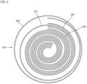
- FIG. 2 is a plan view schematically illustrating an electrode assembly according to an embodiment of the present invention.
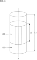
- FIG. 3 is a perspective view schematically illustrating the electrode assembly according to FIG. 1 .
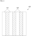
- FIG. 4 is an enlarged plan view of one region of FIG. 3 .
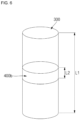
- FIGS. 5 to 7 are perspective views schematically illustrating an attachment form of a finishing tape according to various embodiments of the present invention.
- the electrode assembly 300 is wound in a cylindrical shape with the separator 330 interposed between the negative electrode plate 310 and the positive electrode plate 320. Assuming that a virtual central axis exists in the longitudinal direction of the electrode assembly 300, the central axis becomes a winding axis A.
- the electrode assembly 300 is fixed by the finishing tape 400 and is not unwound.
- the winding start portion of the electrode assembly 300 is defined as the inner end of the electrode assembly 300, and the winding end portion is defined as the outer end portion.
- the finishing tape 400 is attached to cover a portion of the electrode assembly 300 in the direction of the winding axis and is attached to cover the outer peripheral surface of the electrode assembly 300. Accordingly, the finishing tape 400 may be formed in a rectangular shape and attached so as to be wound on the outer peripheral surface of the electrode assembly 300, or may be formed in a cylindrical shape to be inserted into the outer peripheral surface of the electrode assembly 300.
- the length L2 of the finishing tape 400 may be 10 to 100% of L1.
- the length L2 of the finishing tape 400 may be about 60% of the length L1.
- the length L2 of the finishing tape 400a may be about 80% of the length L1
- the length L2 of the finishing tape 400b may be about 20% of L1.
- a finishing tape 400c may include a plurality of tapes having a length of L2, which is about 20% of the length of L1, and attached to the electrode assembly 300.
- the finishing tapes 400c may be spaced apart from each other and attached adjacent to the negative electrode tab 340 and the positive electrode tab 350.
- the finishing tapes 400c may be disposed close to the middle part of L1.
- the finishing tape 400 may include a metallic region 410 and an adhesive region 420.
- the metallic region 410 may be made of the same or similar material as the electrode plate disposed on the outermost side of the last turn of the electrode assembly 300.
- the negative electrode tab 340 is in contact with the can 100 so that the can 100 has a negative polarity, and thus, in FIG. 2 , the negative electrode plate 310 is disposed on the outermost side.
- the metallic region 410 may be made of the same or similar material as that of the negative electrode plate 310. In this case, the metallic region 410 may be made of any one of copper, nickel, and an alloy material of copper and nickel.
- the adhesive region 420 may be formed by applying, coating, or attaching an adhesive material on the metallic region 410.
- the adhesive region 420 may be made of a material having an adhesive property by reacting with the electrolyte within the operating temperature range of the secondary battery.
- the adhesive region 420 may be made of an acrylic or PVdF-based binder material.
- the adhesive region 420 serves to fix the electrode assembly 300 so that the outer end of the electrode assembly 300 is not unwound while being wound.
- the metallic region 410 is a metal material that is a conductor, it may contact the can 100 and serve as a substrate tab. That is, since the metallic region 410 is made of the same material as the negative electrode substrate, the can 100 and the negative electrode substrate of the negative electrode plate 310 may be electrically connected by the metallic region 410. That is, the metallic region 410 enables the movement of electrons, and thus may serve as a tab.
- the electrode assembly 300 has a small diameter, the can 100 and the negative electrode substrate are not brought into contact with each other, and thus may not function as a tab.
- the finishing tape 400 includes the metallic region 410, it is possible to overcome the problem of the negative electrode substrate not functioning as a substrate tab because the negative electrode substrate is not brought into contact with the can 100 according to the change in diameter.
- the adhesive region 420 may be formed to have a predetermined gap on the metallic region 410.
- the adhesive region 420 may be formed on the metallic region 410 in the shape of a plurality of vertical lines having a predetermined width. Therefore, the finishing tape 400 may have a shape in which the metallic region 410 and the adhesive region 420 are alternately arranged. That is, in the metallic region 410, the shape of only a portion where the adhesive region 420 is not formed is exposed.
- the arrangement of the metallic region 410 and the adhesive region 420 is not limited to the above-described embodiment.
- FIGS. 8 to 10 are plan views illustrating portions of finishing tapes according to various embodiments of the present invention.
- an adhesive region 420d may be formed on a metallic region 410d in the shape of a plurality of horizontal lines having a predetermined width. Therefore, the finishing tape 400d may have a shape in which the metallic region 410d and the adhesive region 420d are alternately arranged.
- an adhesive region 420e may be formed on a metallic region 410e in a lattice shape. Accordingly, the metallic region 410e may appear to be arranged on the adhesive region 420e in a plurality of rectangular shapes.
- an adhesive region 420f may be formed on the metallic region 410f in the shape of a plurality of dots having a predetermined size.
- the adhesive region 420f may be arranged on the metallic region 410f at regular intervals.
- the shapes of the finishing tapes 400d to 400f are not limited to those of the above-described embodiments.
- the metallic finishing tape serves as an additional end tab (substrate tab), thereby improving the dispersion of cell performance.
Landscapes
- Chemical & Material Sciences (AREA)
- Chemical Kinetics & Catalysis (AREA)
- Electrochemistry (AREA)
- General Chemical & Material Sciences (AREA)
- Engineering & Computer Science (AREA)
- Manufacturing & Machinery (AREA)
- Inorganic Chemistry (AREA)
- Secondary Cells (AREA)
Abstract
Description
- An embodiment of the present invention relates to a cylindrical secondary battery capable of improving the dispersion of cell performance.
- In general, a cylindrical secondary battery includes a cylindrical electrode assembly, a cylindrical can accommodating the electrode assembly and electrolyte, and a cap assembly coupled to a top opening of the can to seal the can and allow current generated in the electrode assembly to flow to an external device. Specifically, the electrode assembly is formed by winding a negative electrode substrate and a positive electrode substrate into a cylindrical shape, and attaching a tape or the like to prevent the wound end from unwinding.
- Recently, in accordance with the demand for high-output and high-capacity batteries, the need to efficiently design the inner space of a cylindrical can has emerged. Accordingly, it is necessary to improve the finishing structure of a substrate.
- The above information disclosed in this Background section is only for enhancement of understanding of the background of the invention and therefore it may contain information that does not constitute prior art.
- An object of the present invention is to provide a cylindrical secondary battery capable of improving the dispersion of cell performance.
- A cylindrical secondary battery according to an embodiment of the present invention may include: an electrode assembly comprising a negative electrode plate, a positive electrode plate, and a separator interposed between the negative electrode plate and the positive electrode plate, and having a wound shape in one direction; a metallic finishing tape attached to the outer peripheral surface of the electrode assembly so as to cover at least a portion of the electrode assembly; a cylindrical can having one side opened so as to accommodate the electrode assembly along with an electrolyte; and a cap assembly coupled to the open one side of the can so as to seal the can.
- The finishing tape may include a metallic region contacting one side of an inner peripheral surface of the can and an adhesive region formed on the metallic region and attached to the electrode assembly.
- The adhesive region may be repeatedly formed on the metallic region to have a preset shape and spacing.
- The adhesive region may include at least one of a vertical line, a horizontal line, a lattice, and a dot shape.
- The finishing tape may be attached to at least a part of an outer end of the electrode assembly, which is a winding finishing portion.
- On the basis of the direction of the winding axis of the electrode assembly, the length (L2) of the finishing tape may be 10 to 100% of the length (L1) of the electrode assembly.
- The finishing tape may include a plurality of finishing tapes.
- According to an embodiment of the present invention, by applying the metallic tape to the winding finishing portion of the electrode assembly, there is an effect of improving quality distribution of the substrate finishing structure due to dispersion of a major axis. In addition, the metallic tape serves as an additional end tab (substrate tab) to improve cell performance distribution.
-
-
FIG. 1 is a longitudinal cross-sectional view illustrating a general cylindrical secondary battery. -
FIG. 2 is a plan view schematically illustrating an electrode assembly according to an embodiment of the present invention. -
FIG. 3 is a perspective view schematically illustrating the electrode assembly according toFIG. 1 . -
FIG. 4 is an enlarged plan view of one region ofFIG. 3 . -
FIGS. 5 to 7 are perspective views schematically illustrating an attachment form of a finishing tape according to various embodiments of the present invention. -
FIGS. 8 to 10 are plan views illustrating portions of finishing tapes according to various embodiments of the present invention. - Examples of the present invention are provided to more completely explain the present invention to those skilled in the art, and the following examples may be modified in various other forms. The present invention, however, may be embodied in many different forms and should not be construed as being limited to the example (or exemplary) embodiments set forth herein. Rather, these example embodiments are provided so that this invention will be thorough and complete and will convey the aspects and features of the present invention to those skilled in the art.
- In addition, in the accompanying drawings, sizes or thicknesses of various components are exaggerated for brevity and clarity, and like numbers refer to like elements throughout. As used herein, the term "and/or" includes any and all combinations of one or more of the associated listed items. In addition, it will be understood that when an element A is referred to as being "connected to" an element B, the element A can be directly connected to the element B or an intervening element C may be present therebetween such that the element A and the element B are indirectly connected to each other.
- The terminology used herein is for the purpose of describing particular embodiments only and is not intended to be limiting of the invention. As used herein, the singular forms are intended to include the plural forms as well, unless the context clearly indicates otherwise. It will be further understood that the terms that the terms "comprise or include" and/or "comprising or including," when used in this specification, specify the presence of stated features, numbers, steps, operations, elements, and/or components, but do not preclude the presence or addition of one or more other features, numbers, steps, operations, elements, components, and/or groups thereof.
- It will be understood that, although the terms first, second, etc. may be used herein to describe various members, elements, regions, layers and/or sections, these members, elements, regions, layers and/or sections should not be limited by these terms. These terms are only used to distinguish one member, element, region, layer and/or section from another. Thus, for example, a first member, a first element, a first region, a first layer and/or a first section discussed below could be termed a second member, a second element, a second region, a second layer and/or a second section without departing from the teachings of the present invention.
- Spatially relative terms, such as "beneath," "below," "lower," "above," "upper," and the like, may be used herein for ease of description to describe one element or feature's relationship to another element(s) or feature(s) as illustrated in the figures. It will be understood that the spatially relative terms are intended to encompass different orientations of the device in use or operation in addition to the orientation depicted in the figures. For example, if the element or feature in the figures is turned over, elements described as "below" or "beneath" other elements or features would then be oriented "on" or "above" the other elements or features. Thus, the exemplary term "below" can encompass both an orientation of above and below.
- Hereinafter, a cylindrical secondary battery according to an embodiment of the present invention will be described in detail with reference to the accompanying drawings.
-
FIG. 1 is a longitudinal cross-sectional view illustrating a general cylindrical secondary battery. - As shown in
FIG. 1 , a general cylindrical secondary battery 10 may include a cylindrical can 100 having an opening formed at one end in the longitudinal direction, anelectrode assembly 300 accommodated inside the can, and acap assembly 500 inserted into the opening. - The
can 100 includes acircular bottom portion 110 and aside portion 130 extending upward from thebottom portion 110, and the upper portion of theside portion 130 is open (hereinafter referred to as an opening). In the manufacturing process of the secondary battery B, theelectrode assembly 300 is inserted into thecan 100 together with the electrolyte solution through the opening of thecan 100 . Thecan 100 may be made of steel, a steel alloy, nickel-plated steel, a nickel-plated steel alloy, aluminum, an aluminum alloy, or an equivalent thereof, but the material is not limited thereto. - The
cap assembly 500 is inserted into the opening of thecan 100. A separation preventing structure may be formed on the top of thecan 100 to prevent the insertedcap assembly 500 from escaping to the outside through the opening of thecan 100. For example, the separation preventing structure may be abeading part 132 and a crimpingpart 134. - The
electrode assembly 300 includes anegative electrode plate 310 coated with an electrode active material (e.g., graphite, carbon, etc.) on a negative electrode substrate (anode uncoated portion), apositive electrode plate 320 coated with a positive electrode active material (e.g., a transition metal oxide (LiCoO2, LiNiO2, LiMn2O4, etc.), and aseparator 330 disposed between thenegative electrode plate 310 and thepositive electrode plate 320 to prevent a short circuit and allow only the movement of lithium ions. After being wound in a substantially cylindrical shape, thenegative electrode plate 310, thepositive electrode plate 320, and theseparator 330 may be fixed with a finishing tape (seeFIG. 2 , to be described later) to maintain a wound state. In this state, theelectrode assembly 300 may be accommodated inside thecan 100. - The negative electrode substrate of the
negative electrode plate 310 may be copper (Cu) or nickel (Ni) foil, the positive electrode substrate of thepositive electrode plate 320 may be aluminum (Al) foil, theseparator 330 may be polyethylene (PE) or polypropylene (PP), but the above materials are not limited in the present invention. Thenegative electrode tab 340 protruding downward by a certain length may be welded on thenegative electrode plate 310, and thepositive electrode tab 350 protruding downward by a certain length may be welded on thepositive electrode plate 320, but the reverse is also possible. Thenegative electrode tab 340 may be made of copper or nickel, and thepositive electrode tab 350 may be made of aluminum, but the above materials are not limited in the present invention. Thenegative electrode tab 340 may be welded to thebottom portion 110 of thecan 100, and in this case, thecan 100 may operate as a negative electrode. Conversely, thepositive electrode tab 350 may be welded to thebottom portion 110 of thecan 100, and in this case, thecan 100 may operate as a positive electrode. - In addition, a first
insulating plate 360 and a secondinsulating plate 370 may be interposed above and below theelectrode assembly 300. The firstinsulating plate 360 prevents thepositive electrode plate 320 from electrically contacting thebottom portion 110 of thecan 100, and the secondinsulating plate 370 prevents thenegative electrode plate 310 from electrically contacting thecap assembly 500. - Meanwhile, the
finishing tape 400 is attached to the wound end of theelectrode assembly 300 so as not to unwind while theelectrode assembly 300 is wound. -
FIG. 2 is a plan view schematically illustrating an electrode assembly according to an embodiment of the present invention.FIG. 3 is a perspective view schematically illustrating the electrode assembly according toFIG. 1 .FIG. 4 is an enlarged plan view of one region ofFIG. 3 .FIGS. 5 to 7 are perspective views schematically illustrating an attachment form of a finishing tape according to various embodiments of the present invention. - As shown in
FIGS. 2 and3 , theelectrode assembly 300 is wound in a cylindrical shape with theseparator 330 interposed between thenegative electrode plate 310 and thepositive electrode plate 320. Assuming that a virtual central axis exists in the longitudinal direction of theelectrode assembly 300, the central axis becomes a winding axis A. Theelectrode assembly 300 is fixed by the finishingtape 400 and is not unwound. For convenience, the winding start portion of theelectrode assembly 300 is defined as the inner end of theelectrode assembly 300, and the winding end portion is defined as the outer end portion. The finishingtape 400 is attached to cover a portion of theelectrode assembly 300 in the direction of the winding axis and is attached to cover the outer peripheral surface of theelectrode assembly 300. Accordingly, the finishingtape 400 may be formed in a rectangular shape and attached so as to be wound on the outer peripheral surface of theelectrode assembly 300, or may be formed in a cylindrical shape to be inserted into the outer peripheral surface of theelectrode assembly 300. - Assuming that the length of the
electrode assembly 300 in the winding axis direction is L1, the length L2 of the finishingtape 400 based on the same direction may be 10 to 100% of L1. For example, as shown inFIG. 3 , the length L2 of the finishingtape 400 may be about 60% of the length L1. In addition, as shown inFIG. 5 , the length L2 of the finishingtape 400a may be about 80% of the length L1, and as shown inFIG. 6 , the length L2 of the finishingtape 400b may be about 20% of L1. In addition, as shown inFIG. 7 , a finishingtape 400c may include a plurality of tapes having a length of L2, which is about 20% of the length of L1, and attached to theelectrode assembly 300. In this case, the finishingtapes 400c may be spaced apart from each other and attached adjacent to thenegative electrode tab 340 and thepositive electrode tab 350. Alternatively, the finishingtapes 400c may be disposed close to the middle part of L1. - In addition, as shown in
FIG. 4 , the finishingtape 400 may include ametallic region 410 and anadhesive region 420. Themetallic region 410 may be made of the same or similar material as the electrode plate disposed on the outermost side of the last turn of theelectrode assembly 300. For example, as shown inFIG. 1 , thenegative electrode tab 340 is in contact with thecan 100 so that thecan 100 has a negative polarity, and thus, inFIG. 2 , thenegative electrode plate 310 is disposed on the outermost side. Here, themetallic region 410 may be made of the same or similar material as that of thenegative electrode plate 310. In this case, themetallic region 410 may be made of any one of copper, nickel, and an alloy material of copper and nickel. - The
adhesive region 420 may be formed by applying, coating, or attaching an adhesive material on themetallic region 410. Theadhesive region 420 may be made of a material having an adhesive property by reacting with the electrolyte within the operating temperature range of the secondary battery. For example, theadhesive region 420 may be made of an acrylic or PVdF-based binder material. - Here, the
adhesive region 420 serves to fix theelectrode assembly 300 so that the outer end of theelectrode assembly 300 is not unwound while being wound. In addition, since themetallic region 410 is a metal material that is a conductor, it may contact thecan 100 and serve as a substrate tab. That is, since themetallic region 410 is made of the same material as the negative electrode substrate, thecan 100 and the negative electrode substrate of thenegative electrode plate 310 may be electrically connected by themetallic region 410. That is, themetallic region 410 enables the movement of electrons, and thus may serve as a tab. When theelectrode assembly 300 has a small diameter, thecan 100 and the negative electrode substrate are not brought into contact with each other, and thus may not function as a tab. However, when the finishingtape 400 includes themetallic region 410, it is possible to overcome the problem of the negative electrode substrate not functioning as a substrate tab because the negative electrode substrate is not brought into contact with thecan 100 according to the change in diameter. - The
adhesive region 420 may be formed to have a predetermined gap on themetallic region 410. For example, as shown inFIG. 4 , theadhesive region 420 may be formed on themetallic region 410 in the shape of a plurality of vertical lines having a predetermined width. Therefore, the finishingtape 400 may have a shape in which themetallic region 410 and theadhesive region 420 are alternately arranged. That is, in themetallic region 410, the shape of only a portion where theadhesive region 420 is not formed is exposed. - However, the arrangement of the
metallic region 410 and theadhesive region 420 is not limited to the above-described embodiment. -
FIGS. 8 to 10 are plan views illustrating portions of finishing tapes according to various embodiments of the present invention. - As shown in
FIG. 8 , in a finishingtape 400d according to another embodiment of the present invention, anadhesive region 420d may be formed on ametallic region 410d in the shape of a plurality of horizontal lines having a predetermined width. Therefore, the finishingtape 400d may have a shape in which themetallic region 410d and theadhesive region 420d are alternately arranged. - In addition, as shown in
FIG. 9 , in a finishingtape 400e according to another embodiment of the present invention, anadhesive region 420e may be formed on ametallic region 410e in a lattice shape. Accordingly, themetallic region 410e may appear to be arranged on theadhesive region 420e in a plurality of rectangular shapes. - In addition, as shown in
FIG. 10 , in a finishingtape 400f according to another embodiment of the present invention, anadhesive region 420f may be formed on themetallic region 410f in the shape of a plurality of dots having a predetermined size. Theadhesive region 420f may be arranged on themetallic region 410f at regular intervals. - However, the shapes of the finishing
tapes 400d to 400f are not limited to those of the above-described embodiments. - As described above, by applying a metallic finishing tape to the winding finishing portion of the electrode assembly, there is an effect of improving dispersion of quality of the substrate finishing structure due to dispersion of a major axis. In addition, the metallic finishing tape serves as an additional end tab (substrate tab), thereby improving the dispersion of cell performance.
- What has been described above is only one embodiment for carrying out the present invention, and the present invention is not limited to the above-described embodiment. However, the technical spirit of the present invention lies in that anyone skilled in the art could make various changes, as claimed in the claims below, without departing from the gist of the present invention.
Claims (7)
- A cylindrical secondary battery comprising:an electrode assembly comprising a negative electrode plate, a positive electrode plate, and a separator interposed between the negative electrode plate and the positive electrode plate, and having a wound shape in one direction;a metallic finishing tape attached to the outer peripheral surface of the electrode assembly so as to cover at least a portion of the electrode assembly;a cylindrical can having one side opened so as to accommodate the electrode assembly along with an electrolyte; anda cap assembly coupled to the open one side of the can so as to seal the can.
- The cylindrical secondary battery of claim 1, wherein the finishing tape includes a metallic region contacting one side of an inner peripheral surface of the can and an adhesive region formed on the metallic region and attached to the electrode assembly.
- The cylindrical secondary battery of claim 2, wherein the adhesive region is repeatedly formed on the metallic region to have a preset shape and spacing.
- The cylindrical secondary battery of claim 3, wherein the adhesive region includes at least one of a vertical line, a horizontal line, a lattice, and a dot shape.
- The cylindrical secondary battery of claim 1, wherein the finishing tape is attached to at least a part of an outer end of the electrode assembly, which is a winding finishing portion.
- The cylindrical secondary battery of claim 1, wherein on the basis of the direction of the winding axis of the electrode assembly, the length (L2) of the finishing tape is 10 to 100% of the length (L1) of the electrode assembly.
- The cylindrical secondary battery of claim 6, wherein the finishing tape includes a plurality of finishing tapes.
Applications Claiming Priority (2)
| Application Number | Priority Date | Filing Date | Title |
|---|---|---|---|
| KR1020210044577A KR20220138652A (en) | 2021-04-06 | 2021-04-06 | Cylindrical secondary battery |
| PCT/KR2022/004211 WO2022215918A1 (en) | 2021-04-06 | 2022-03-25 | Cylindrical secondary battery |
Publications (2)
| Publication Number | Publication Date |
|---|---|
| EP4322270A1 true EP4322270A1 (en) | 2024-02-14 |
| EP4322270A4 EP4322270A4 (en) | 2025-10-08 |
Family
ID=83546448
Family Applications (1)
| Application Number | Title | Priority Date | Filing Date |
|---|---|---|---|
| EP22784828.0A Pending EP4322270A4 (en) | 2021-04-06 | 2022-03-25 | CYLINDRICAL SECONDARY BATTERY |
Country Status (5)
| Country | Link |
|---|---|
| US (1) | US12555879B2 (en) |
| EP (1) | EP4322270A4 (en) |
| KR (1) | KR20220138652A (en) |
| CN (1) | CN116868393A (en) |
| WO (1) | WO2022215918A1 (en) |
Families Citing this family (3)
| Publication number | Priority date | Publication date | Assignee | Title |
|---|---|---|---|---|
| WO2025216229A1 (en) * | 2024-04-09 | 2025-10-16 | パナソニックIpマネジメント株式会社 | Secondary battery |
| WO2025216230A1 (en) * | 2024-04-09 | 2025-10-16 | パナソニックIpマネジメント株式会社 | Secondary battery |
| KR20260000251A (en) * | 2024-06-25 | 2026-01-02 | 삼성에스디아이 주식회사 | Battery and method of manufacturing same |
Family Cites Families (11)
| Publication number | Priority date | Publication date | Assignee | Title |
|---|---|---|---|---|
| JP2002110222A (en) | 2000-10-03 | 2002-04-12 | Sanyo Electric Co Ltd | Cylindrical storage battery |
| JP2003168413A (en) * | 2001-11-30 | 2003-06-13 | Sanyo Electric Co Ltd | Battery and manufacturing method thereof |
| JP2003173815A (en) | 2001-12-06 | 2003-06-20 | Matsushita Electric Ind Co Ltd | Sealed rectangular alkaline storage battery |
| KR100719725B1 (en) * | 2005-12-29 | 2007-05-17 | 삼성에스디아이 주식회사 | Electrode assembly for lithium secondary battery and lithium secondary battery using same |
| JP4931492B2 (en) | 2006-06-28 | 2012-05-16 | 三洋電機株式会社 | Cylindrical storage battery |
| KR101001325B1 (en) * | 2007-07-16 | 2010-12-14 | 주식회사 엘지화학 | Jelly-roll having a structure in which an elastic member is attached to a plain portion and a secondary battery including the same |
| KR101310486B1 (en) | 2008-04-03 | 2013-09-24 | 주식회사 엘지화학 | Seal tape and secondary battery comprising the same |
| KR102312279B1 (en) | 2016-10-17 | 2021-10-12 | 삼성에스디아이 주식회사 | Rechargeable battery |
| WO2018105398A1 (en) * | 2016-12-05 | 2018-06-14 | 三洋電機株式会社 | Cylindrical nonaqueous electrolyte secondary battery |
| KR20190090547A (en) * | 2018-01-25 | 2019-08-02 | 삼성에스디아이 주식회사 | Secondary Battery |
| KR102459970B1 (en) | 2018-11-27 | 2022-10-26 | 주식회사 엘지에너지솔루션 | Cylindrical type secondary battery |
-
2021
- 2021-04-06 KR KR1020210044577A patent/KR20220138652A/en active Pending
-
2022
- 2022-03-25 US US18/003,957 patent/US12555879B2/en active Active
- 2022-03-25 EP EP22784828.0A patent/EP4322270A4/en active Pending
- 2022-03-25 WO PCT/KR2022/004211 patent/WO2022215918A1/en not_active Ceased
- 2022-03-25 CN CN202280015554.1A patent/CN116868393A/en active Pending
Also Published As
| Publication number | Publication date |
|---|---|
| CN116868393A (en) | 2023-10-10 |
| US12555879B2 (en) | 2026-02-17 |
| KR20220138652A (en) | 2022-10-13 |
| WO2022215918A1 (en) | 2022-10-13 |
| US20230261352A1 (en) | 2023-08-17 |
| EP4322270A4 (en) | 2025-10-08 |
Similar Documents
| Publication | Publication Date | Title |
|---|---|---|
| KR102712362B1 (en) | Secondary battery | |
| CN113853702B (en) | Secondary battery | |
| EP4303975A1 (en) | Cylindrical secondary battery and method for manufacturing secondary battery | |
| US9478781B2 (en) | Electrode assembly and secondary battery using the same | |
| US12555879B2 (en) | Cylindrical secondary battery | |
| US8679673B2 (en) | Cap assembly, can, and secondary battery employing the same | |
| US20230011273A1 (en) | Rechargeable battery | |
| US9887412B2 (en) | Rechargeable battery having upper insulator member | |
| US20240097297A1 (en) | Cylindrical secondary battery | |
| EP4250411A1 (en) | Secondary battery | |
| CN116470199A (en) | Cylindrical secondary battery | |
| EP4593165A1 (en) | Cylindrical secondary battery | |
| US20080226981A1 (en) | Center pin cylindrical secondary battery and cylindrical secondary battery having the same | |
| CN118676545A (en) | External terminal connection structure of secondary battery and secondary battery | |
| EP4311014A1 (en) | Cylindrical secondary battery | |
| EP4164051A1 (en) | Secondary battery | |
| EP4636879A1 (en) | Secondary battery | |
| US20260112681A1 (en) | Secondary battery and method for manufacturing the same | |
| KR102860189B1 (en) | Secondary battery | |
| US20240186661A1 (en) | Secondary battery | |
| US20250070331A1 (en) | Secondary battery | |
| EP4475244A2 (en) | Cylindrical secondary battery | |
| US20250210826A1 (en) | Battery | |
| EP4383400A1 (en) | Cylindrical secondary battery | |
| KR20250170416A (en) | Electrode assembly and rechargeable battery including the same |
Legal Events
| Date | Code | Title | Description |
|---|---|---|---|
| STAA | Information on the status of an ep patent application or granted ep patent |
Free format text: STATUS: THE INTERNATIONAL PUBLICATION HAS BEEN MADE |
|
| PUAI | Public reference made under article 153(3) epc to a published international application that has entered the european phase |
Free format text: ORIGINAL CODE: 0009012 |
|
| STAA | Information on the status of an ep patent application or granted ep patent |
Free format text: STATUS: REQUEST FOR EXAMINATION WAS MADE |
|
| 17P | Request for examination filed |
Effective date: 20231003 |
|
| AK | Designated contracting states |
Kind code of ref document: A1 Designated state(s): AL AT BE BG CH CY CZ DE DK EE ES FI FR GB GR HR HU IE IS IT LI LT LU LV MC MK MT NL NO PL PT RO RS SE SI SK SM TR |
|
| DAV | Request for validation of the european patent (deleted) | ||
| DAX | Request for extension of the european patent (deleted) | ||
| A4 | Supplementary search report drawn up and despatched |
Effective date: 20250909 |
|
| RIC1 | Information provided on ipc code assigned before grant |
Ipc: H01M 10/04 20060101AFI20250903BHEP Ipc: H01M 10/0587 20100101ALI20250903BHEP Ipc: H01M 50/534 20210101ALI20250903BHEP Ipc: H01M 50/533 20210101ALI20250903BHEP Ipc: H01M 50/474 20210101ALI20250903BHEP Ipc: H01M 50/477 20210101ALI20250903BHEP Ipc: H01M 50/483 20210101ALI20250903BHEP Ipc: H01M 50/536 20210101ALI20250903BHEP Ipc: H01M 50/545 20210101ALI20250903BHEP Ipc: H01M 50/56 20210101ALI20250903BHEP Ipc: H01M 50/107 20210101ALI20250903BHEP Ipc: H01M 50/152 20210101ALI20250903BHEP Ipc: H01M 50/538 20210101ALI20250903BHEP |