EP4322186A2 - Inductive apparatus with helical coil frame - Google Patents
Inductive apparatus with helical coil frame Download PDFInfo
- Publication number
- EP4322186A2 EP4322186A2 EP23188759.7A EP23188759A EP4322186A2 EP 4322186 A2 EP4322186 A2 EP 4322186A2 EP 23188759 A EP23188759 A EP 23188759A EP 4322186 A2 EP4322186 A2 EP 4322186A2
- Authority
- EP
- European Patent Office
- Prior art keywords
- helical
- frame
- core
- major surfaces
- coils
- Prior art date
- Legal status (The legal status is an assumption and is not a legal conclusion. Google has not performed a legal analysis and makes no representation as to the accuracy of the status listed.)
- Pending
Links
- 230000001939 inductive effect Effects 0.000 title description 7
- 239000004020 conductor Substances 0.000 claims description 11
- 239000012809 cooling fluid Substances 0.000 claims description 5
- 238000004804 winding Methods 0.000 description 19
- 238000001816 cooling Methods 0.000 description 6
- 238000004891 communication Methods 0.000 description 3
- 230000001965 increasing effect Effects 0.000 description 3
- 238000006243 chemical reaction Methods 0.000 description 2
- 239000003989 dielectric material Substances 0.000 description 2
- 238000004519 manufacturing process Methods 0.000 description 2
- 238000000034 method Methods 0.000 description 2
- 238000012986 modification Methods 0.000 description 2
- 230000004048 modification Effects 0.000 description 2
- 239000000843 powder Substances 0.000 description 2
- 230000000717 retained effect Effects 0.000 description 2
- 239000000654 additive Substances 0.000 description 1
- 230000000996 additive effect Effects 0.000 description 1
- 238000013459 approach Methods 0.000 description 1
- 230000015556 catabolic process Effects 0.000 description 1
- 239000000919 ceramic Substances 0.000 description 1
- 238000010586 diagram Methods 0.000 description 1
- 229910003460 diamond Inorganic materials 0.000 description 1
- 239000010432 diamond Substances 0.000 description 1
- 239000000428 dust Substances 0.000 description 1
- 238000005538 encapsulation Methods 0.000 description 1
- 239000012530 fluid Substances 0.000 description 1
- 239000007789 gas Substances 0.000 description 1
- 230000017525 heat dissipation Effects 0.000 description 1
- 238000002955 isolation Methods 0.000 description 1
- 239000000463 material Substances 0.000 description 1
- 230000003071 parasitic effect Effects 0.000 description 1
- 230000002093 peripheral effect Effects 0.000 description 1
- 239000011295 pitch Substances 0.000 description 1
- HBMJWWWQQXIZIP-UHFFFAOYSA-N silicon carbide Chemical compound [Si+]#[C-] HBMJWWWQQXIZIP-UHFFFAOYSA-N 0.000 description 1
Images







Classifications
-
- H—ELECTRICITY
- H01—ELECTRIC ELEMENTS
- H01F—MAGNETS; INDUCTANCES; TRANSFORMERS; SELECTION OF MATERIALS FOR THEIR MAGNETIC PROPERTIES
- H01F27/00—Details of transformers or inductances, in general
- H01F27/02—Casings
- H01F27/025—Constructional details relating to cooling
-
- H—ELECTRICITY
- H01—ELECTRIC ELEMENTS
- H01F—MAGNETS; INDUCTANCES; TRANSFORMERS; SELECTION OF MATERIALS FOR THEIR MAGNETIC PROPERTIES
- H01F27/00—Details of transformers or inductances, in general
- H01F27/28—Coils; Windings; Conductive connections
- H01F27/30—Fastening or clamping coils, windings, or parts thereof together; Fastening or mounting coils or windings on core, casing, or other support
- H01F27/306—Fastening or mounting coils or windings on core, casing or other support
-
- H—ELECTRICITY
- H01—ELECTRIC ELEMENTS
- H01F—MAGNETS; INDUCTANCES; TRANSFORMERS; SELECTION OF MATERIALS FOR THEIR MAGNETIC PROPERTIES
- H01F27/00—Details of transformers or inductances, in general
- H01F27/24—Magnetic cores
-
- H—ELECTRICITY
- H01—ELECTRIC ELEMENTS
- H01F—MAGNETS; INDUCTANCES; TRANSFORMERS; SELECTION OF MATERIALS FOR THEIR MAGNETIC PROPERTIES
- H01F27/00—Details of transformers or inductances, in general
- H01F27/28—Coils; Windings; Conductive connections
- H01F27/2823—Wires
-
- H—ELECTRICITY
- H01—ELECTRIC ELEMENTS
- H01F—MAGNETS; INDUCTANCES; TRANSFORMERS; SELECTION OF MATERIALS FOR THEIR MAGNETIC PROPERTIES
- H01F27/00—Details of transformers or inductances, in general
- H01F27/28—Coils; Windings; Conductive connections
- H01F27/2847—Sheets; Strips
-
- H—ELECTRICITY
- H01—ELECTRIC ELEMENTS
- H01F—MAGNETS; INDUCTANCES; TRANSFORMERS; SELECTION OF MATERIALS FOR THEIR MAGNETIC PROPERTIES
- H01F27/00—Details of transformers or inductances, in general
- H01F27/28—Coils; Windings; Conductive connections
- H01F27/2895—Windings disposed upon ring cores
-
- H—ELECTRICITY
- H01—ELECTRIC ELEMENTS
- H01F—MAGNETS; INDUCTANCES; TRANSFORMERS; SELECTION OF MATERIALS FOR THEIR MAGNETIC PROPERTIES
- H01F27/00—Details of transformers or inductances, in general
- H01F27/28—Coils; Windings; Conductive connections
- H01F27/32—Insulating of coils, windings, or parts thereof
- H01F27/323—Insulation between winding turns, between winding layers
-
- H—ELECTRICITY
- H01—ELECTRIC ELEMENTS
- H01F—MAGNETS; INDUCTANCES; TRANSFORMERS; SELECTION OF MATERIALS FOR THEIR MAGNETIC PROPERTIES
- H01F27/00—Details of transformers or inductances, in general
- H01F27/28—Coils; Windings; Conductive connections
- H01F27/32—Insulating of coils, windings, or parts thereof
- H01F27/324—Insulation between coil and core, between different winding sections, around the coil; Other insulation structures
- H01F27/325—Coil bobbins
-
- H—ELECTRICITY
- H01—ELECTRIC ELEMENTS
- H01F—MAGNETS; INDUCTANCES; TRANSFORMERS; SELECTION OF MATERIALS FOR THEIR MAGNETIC PROPERTIES
- H01F27/00—Details of transformers or inductances, in general
- H01F27/08—Cooling; Ventilating
- H01F27/10—Liquid cooling
- H01F27/18—Liquid cooling by evaporating liquids
Definitions
- the inventive subject matter relates to passive circuit components and, more particularly, to inductive devices.
- Power conversion circuits for applications such as power supplies, solid-state transformers and motor drives typically include inductive components such as transformers and various types of inductors.
- inductive components such as transformers and various types of inductors.
- SiC silicon carbide
- these components need to operate reliably under dramatically increased voltage gradients, amplitudes, and switching frequencies while utilizing space-efficient designs with adequate cooling and desirably low levels of unwanted parasitic effects. Accordingly, there is a need for compact inductive components that can withstand high voltages without arcing or dielectric breakdowns while operating effectively at high frequencies.
- an apparatus including a core and a helical frame coaxial with a segment of the core and having first and second major surfaces on opposite sides of the helical frame and each normal to a surface of the segment.
- At least one helical coil conforms to at least one of the first and second major surfaces.
- the at least one helical coil may include a helical ribbon conductor having a major surface disposed parallel to one of the first and second major surfaces.
- the at least one helical coil may include a plurality of concentric helical coils disposed parallel to one of the first and second major surfaces.
- the concentric helical coils may include concentric ribbon conductors having major surfaces arrayed in a plane normal to the one of the first and second major surfaces.
- the at least one helical coil may include first and second helical coils conforming to respective ones of the first and second major surfaces.
- the first helical coil may include a helical ribbon conductor having a major surface disposed parallel to the first major surface of the helical frame.
- the second helical coil may include a plurality of concentric helical coils arrayed parallel to the second major surface of the helical frame.
- the helical frame may include a plurality of interconnected modular segments.
- the segment of the core may be linear.
- Still further embodiments provide an apparatus including a toroidal core comprising a linear segment.
- a helical frame is coaxial with the linear segment and has first and second major surfaces on opposite sides of the helical frame and each normal to a surface of the linear segment of the toroidal core.
- First and second helical coils conform to respective ones of the first and second major surfaces of the helical frame.
- Additional embodiments provide a transformer including a core comprising a linear segment and a helical frame coaxial with the linear segment and having first and second major surfaces on opposite sides of the helical frame and each normal to the linear segment.
- the transformer further includes a first helical coil conforming to the first major surface and a second helical coil conforming to the second major surface.
- the transformer may further include an enclosure containing the core, the helical frame and the first and second helical coils therein and a conduit disposed in the enclosure, surrounding the core, the helical frame and the first and second helical coils, and configured to circulate a cooling fluid.
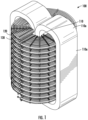
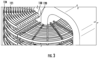
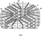
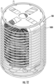
- FIGs. 1-4 are perspective views of an inductive apparatus according to some embodiments.
- these figures show a transformer 100 including a toroidal core 110.
- a helical frame 120 surrounds a linear section 110a of the core 110 and supports first and second windings 130, 140.
- the helical frame 120 has first and second major surfaces 121, 123 on opposite sides of the frame 120.
- the first and second major surfaces 121, 123 are arranged generally normal to a surface of the core 110.
- the first winding 130 here shown as comprising concentric ribbon-like conductors retained in a spaced apart manner using retainer members 124 extending from the first surface 121, conforms to the first surface 121 of the helical frame 120.
- the ribbon conductors of the first winding 130 have major surfaces generally normal to the first surface 121 and parallel to the axis of the core 110.
- the second winding 130 is shown as a single flat ribbon-like conductor having major surfaces generally normal to the axis of the core 110 and conforming to the second surface 123 of the helical frame 120.
- the second winding 140 is retained by retaining members 126 extending from the second major surface 123 of the helical frame 120.
- the first winding 130 e.g., a low current winding
- the second winding 140 e.g., a high-current winding.
- the helical frame 120 may be fabricated using, for example, 3-D printing techniques. This can allow for efficient fabrication of helical frames having various pitches and providing various incline angles for the windings 130, 140 in relation to the axis and/or surface of the core 110. As explained below, the frame 120 may be constructed in modular fashion the can support a variety of different coil arrangements.
- FIGs. 5-7 illustrate the frame 120 with the windings 130, 140 removed.
- the frame 120 may be constructed from modular sections 120a, here shown as joined together using bolts 122.
- This modular structure allows helical frames with various numbers of turns to be fabricated to suit various applications. While the sections 120a illustrated are quarter-turn sections, it will be appreciated that other types of modular sections may be used (e.g., half- or full-turn sections). It will be further appreciated that such sections may be joined in various other ways to form a helical frame.
- FIG. 8 illustrates a modular section 130a of the first winding 130.
- Various numbers of such sections 130a may be joined (e.g., soldered, welded, brazed, or otherwise electrically and mechanically connected) to one another at their ends 132 produce windings with various numbers of turns.
- the ends 132 of terminal ones of the sections 130a may be selectively joined to one another to produce windings with various numbers of turns.
- FIG. 9 illustrates a modular section 140a of the second winding 140.
- Various numbers of such sections 140a may be joined to one another at their ends 142 to produce windings with various numbers of turns.
- This modular approach involves using discrete parts that are adaptable to relatively simple additive manufacturing systems. It will be understood that some embodiments may be implemented using advanced 3-D printing techniques that involve printing components such as the helical frame 120 and the windings 130, 140.
- inductive apparatus along the lines described above may be housed in an enclosure that can provide EMI shielding, support encapsulation in dielectric material and/or support structures for cooling the apparatus.
- the transformer apparatus 100 of FIGs. 1-4 may be encased in a cylindrical enclosure 1000 that is sealed by a top cover 1010.
- the enclosure 1000 may be filled with a high dielectric material, such as a high dielectric fluid, gas or powder, to increase isolation between the components of the transformer from one another and surrounding structures.
- the filling material may also be a thermally conductive material, such as diamond dust or ceramic powder, configured to convey heat away from the transformer 100 and to, for example, a spiral or serpentine cooling conduit 1020 surrounding the transformer 100 within the enclosure 1000.
- the cooling conduit 1020 may be configured to convey a cooling fluid from a source external to the enclosure 1000 to carry heat away from the interior of the enclosure 1000.
- FIG. 14 shows an alternative arrangement in which an array of peripheral cooling fluid conduits 1420 (e.g., heat pipes) surrounds the transformer 100 and acts to carry heat away from a transformer 100 to a radiator or other heat dissipation structure.
- peripheral cooling fluid conduits 1420 e.g., heat pipes
- FIGs. 1-14 is provided for purposes of illustration of example embodiments, and that other embodiments may take various other forms within the scope of the inventive subject matter.
- other embodiments may incorporate only one winding (e.g., only one of the windings 130, 140 illustrated) for use as an inductor.
- Other embodiments may use different core structures, e.g., rather than the oval toroidal core illustrated, a circular or elliptical toroidal core may be used.
- Some embodiments may include a helical frame and coil(s) that completely or partially surrounds such a circular or elliptical toroidal core.
Landscapes
- Engineering & Computer Science (AREA)
- Power Engineering (AREA)
- Coils Of Transformers For General Uses (AREA)
- Coils Or Transformers For Communication (AREA)
Abstract
Description
- The inventive subject matter relates to passive circuit components and, more particularly, to inductive devices.
- Power conversion circuits for applications such as power supplies, solid-state transformers and motor drives typically include inductive components such as transformers and various types of inductors. With the increasing use of high-voltage power switching devices, such as silicon carbide (SiC) based transistors, in power conversion circuits, increased demands are placed on such components. In particular, these components need to operate reliably under dramatically increased voltage gradients, amplitudes, and switching frequencies while utilizing space-efficient designs with adequate cooling and desirably low levels of unwanted parasitic effects. Accordingly, there is a need for compact inductive components that can withstand high voltages without arcing or dielectric breakdowns while operating effectively at high frequencies.
- Some embodiments provide an apparatus including a core and a helical frame coaxial with a segment of the core and having first and second major surfaces on opposite sides of the helical frame and each normal to a surface of the segment. At least one helical coil conforms to at least one of the first and second major surfaces. In some embodiments, the at least one helical coil may include a helical ribbon conductor having a major surface disposed parallel to one of the first and second major surfaces. In some embodiments, the at least one helical coil may include a plurality of concentric helical coils disposed parallel to one of the first and second major surfaces. The concentric helical coils may include concentric ribbon conductors having major surfaces arrayed in a plane normal to the one of the first and second major surfaces.
- According to further embodiments, the at least one helical coil may include first and second helical coils conforming to respective ones of the first and second major surfaces. The first helical coil may include a helical ribbon conductor having a major surface disposed parallel to the first major surface of the helical frame. The second helical coil may include a plurality of concentric helical coils arrayed parallel to the second major surface of the helical frame.
- According to further aspects, the helical frame may include a plurality of interconnected modular segments. The segment of the core may be linear.
- Still further embodiments provide an apparatus including a toroidal core comprising a linear segment. A helical frame is coaxial with the linear segment and has first and second major surfaces on opposite sides of the helical frame and each normal to a surface of the linear segment of the toroidal core. First and second helical coils conform to respective ones of the first and second major surfaces of the helical frame.
- Additional embodiments provide a transformer including a core comprising a linear segment and a helical frame coaxial with the linear segment and having first and second major surfaces on opposite sides of the helical frame and each normal to the linear segment. The transformer further includes a first helical coil conforming to the first major surface and a second helical coil conforming to the second major surface. The transformer may further include an enclosure containing the core, the helical frame and the first and second helical coils therein and a conduit disposed in the enclosure, surrounding the core, the helical frame and the first and second helical coils, and configured to circulate a cooling fluid.
-
-
FIG. 1 is a perspective view of a transformer according to some embodiments of the inventive subject matter. -
FIG. 2 is another perspective view of the transformer ofFIG. 1 . -
FIG. 3 is a detailed perspective view of the transformer ofFIG. 1 . -
FIG. 4 is another detailed perspective view of the transformer ofFIG. 1 . -
FIG. 5 is a perspective view of a helical coil frame of the transformer ofFIG. 1 . -
FIG. 6 is a detailed perspective view of the helical coil frame of the transformer ofFIG. 1 . -
FIG. 7 is another perspective view of the helical coil frame of the transformer ofFIG. 1 . -
FIG. 8 is a perspective view of a section of a first coil of the transformer ofFIG. 1 . -
FIG. 9 . is a perspective view of second of a second coil of the transformer ofFIG. 1 . -
FIG. 10 is a perspective view of an enclosed version of the transformer ofFIG. 1 according to some embodiments. -
FIG. 11 is a perspective view of the enclosure transformer ofFIG. 10 with a top cover removed to show the transformer ofFIG. 1 . -
FIG. 12 is a perspective view of the enclosed transformer ofFIG. 10 with the enclosure removed to show a cooling conduit coil according to some embodiments. -
FIG. 13 is a cross-section view corresponding to the perspective view ofFIG. 12 . -
FIG. 14 is a perspective view of an enclosed transformer with cooling conduits according to further embodiments. - The inventive concept will be described more fully hereinafter with reference to the accompanying figures, in which embodiments of the inventive concept are shown. This inventive concept may, however, be embodied in many alternate forms and should not be construed as limited to the embodiments set forth herein.
- Accordingly, while the inventive concept is susceptible to various modifications and alternative forms, specific embodiments thereof are shown by way of example in the drawings and will herein be described in detail. It should be understood, however, that there is no intent to limit the inventive concept to the particular forms disclosed, but on the contrary, the inventive concept is to cover all modifications, equivalents, and alternatives falling within the spirit and scope of the inventive concept as defined by the claims. Like numbers refer to like elements throughout the description of the figures.
- The terminology used herein is for the purpose of describing particular embodiments only and is not intended to be limiting of the inventive concept. As used herein, the singular forms "a", "an" and "the" are intended to include the plural forms as well, unless the context clearly indicates otherwise. It will be further understood that the terms "comprises," "comprising," "includes" and/or "including" when used in this specification, specify the presence of stated features, integers, steps, operations, elements, and/or components, but do not preclude the presence or addition of one or more other features, integers, steps, operations, elements, components, and/or groups thereof. Moreover, when an element is referred to as being "responsive" or "connected" to another element, it can be directly responsive or connected to the other element, or intervening elements may be present. In contrast, when an element is referred to as being "directly responsive" or "directly connected" to another element, there are no intervening elements present. As used herein the term "and/or" includes any and all combinations of one or more of the associated listed items and may be abbreviated as "/".
- Unless otherwise defined, all terms (including technical and scientific terms) used herein have the same meaning as commonly understood by one of ordinary skill in the art to which this inventive concept belongs. It will be further understood that terms used herein should be interpreted as having a meaning that is consistent with their meaning in the context of this specification and the relevant art and will not be interpreted in an idealized or overly formal sense unless expressly so defined herein.
- It will be understood that, although the terms first, second, etc., may be used herein to describe various elements, these elements should not be limited by these terms. These terms are only used to distinguish one element from another. For example, a first element could be termed a second element, and, similarly, a second element could be termed a first element without departing from the teachings of the disclosure. Although some of the diagrams include arrows on communication paths to show a primary direction of communication, it is to be understood that communication may occur in the opposite direction to the depicted arrows.
-
FIGs. 1-4 are perspective views of an inductive apparatus according to some embodiments. In particular, these figures show atransformer 100 including atoroidal core 110. Ahelical frame 120 surrounds alinear section 110a of thecore 110 and supports first andsecond windings helical frame 120 has first and secondmajor surfaces frame 120. The first and secondmajor surfaces core 110. - The
first winding 130, here shown as comprising concentric ribbon-like conductors retained in a spaced apart manner usingretainer members 124 extending from thefirst surface 121, conforms to thefirst surface 121 of thehelical frame 120. The ribbon conductors of thefirst winding 130 have major surfaces generally normal to thefirst surface 121 and parallel to the axis of thecore 110. Thesecond winding 130 is shown as a single flat ribbon-like conductor having major surfaces generally normal to the axis of thecore 110 and conforming to thesecond surface 123 of thehelical frame 120. The second winding 140 is retained by retainingmembers 126 extending from the secondmajor surface 123 of thehelical frame 120. - The first winding 130, e.g., a low current winding, is held in a position normal to the second winding 140, e.g., a high-current winding. The
helical frame 120 may be fabricated using, for example, 3-D printing techniques. This can allow for efficient fabrication of helical frames having various pitches and providing various incline angles for thewindings core 110. As explained below, theframe 120 may be constructed in modular fashion the can support a variety of different coil arrangements. -
FIGs. 5-7 illustrate theframe 120 with thewindings FIG. 6 , theframe 120 may be constructed frommodular sections 120a, here shown as joined together usingbolts 122. This modular structure allows helical frames with various numbers of turns to be fabricated to suit various applications. While thesections 120a illustrated are quarter-turn sections, it will be appreciated that other types of modular sections may be used (e.g., half- or full-turn sections). It will be further appreciated that such sections may be joined in various other ways to form a helical frame. -
FIG. 8 illustrates amodular section 130a of the first winding 130. Various numbers ofsuch sections 130a may be joined (e.g., soldered, welded, brazed, or otherwise electrically and mechanically connected) to one another at theirends 132 produce windings with various numbers of turns. In some embodiments, theends 132 of terminal ones of thesections 130a, may be selectively joined to one another to produce windings with various numbers of turns.FIG. 9 illustrates amodular section 140a of the second winding 140. Various numbers ofsuch sections 140a may be joined to one another at theirends 142 to produce windings with various numbers of turns. This modular approach involves using discrete parts that are adaptable to relatively simple additive manufacturing systems. It will be understood that some embodiments may be implemented using advanced 3-D printing techniques that involve printing components such as thehelical frame 120 and thewindings - In some embodiments, inductive apparatus along the lines described above may be housed in an enclosure that can provide EMI shielding, support encapsulation in dielectric material and/or support structures for cooling the apparatus. Referring to
FIGs. 10-13 , thetransformer apparatus 100 ofFIGs. 1-4 may be encased in acylindrical enclosure 1000 that is sealed by atop cover 1010. Theenclosure 1000 may be filled with a high dielectric material, such as a high dielectric fluid, gas or powder, to increase isolation between the components of the transformer from one another and surrounding structures. The filling material may also be a thermally conductive material, such as diamond dust or ceramic powder, configured to convey heat away from thetransformer 100 and to, for example, a spiral orserpentine cooling conduit 1020 surrounding thetransformer 100 within theenclosure 1000. Thecooling conduit 1020 may be configured to convey a cooling fluid from a source external to theenclosure 1000 to carry heat away from the interior of theenclosure 1000.FIG. 14 shows an alternative arrangement in which an array of peripheral cooling fluid conduits 1420 (e.g., heat pipes) surrounds thetransformer 100 and acts to carry heat away from atransformer 100 to a radiator or other heat dissipation structure. - It will be appreciated that the inductive apparatus illustrated in
FIGs. 1-14 is provided for purposes of illustration of example embodiments, and that other embodiments may take various other forms within the scope of the inventive subject matter. For example, other embodiments may incorporate only one winding (e.g., only one of thewindings - In the drawings and specification, there have been disclosed typical preferred embodiments of the invention and, although specific terms are employed, they are used in a generic and descriptive sense only and not for purposes of limitation, the scope of the invention being set forth in the following claims.
Claims (15)
- An apparatus comprising:a core;a helical frame coaxial with a segment of the core and having first and second major surfaces on opposite sides of the helical frame and each normal to a surface of the segment; andat least one helical coil conforming to at least one of the first and second major surfaces.
- The apparatus of claim 1, wherein the at least one helical coil comprises a helical ribbon conductor having a major surface disposed parallel to one of the first and second major surfaces.
- The apparatus of claim 1, wherein the at least one helical coil comprises a plurality of concentric helical coils disposed parallel to one of the first and second major surfaces.
- The apparatus of claim 3, wherein the concentric helical coils comprise concentric ribbon conductors having major surfaces arrayed in a plane normal to the one of the first and second major surfaces.
- The apparatus of claim 1, wherein the at least one helical coil comprises first and second helical coils conforming to respective ones of the first and second major surfaces.
- The apparatus of claim 5, wherein the first helical coil comprises a helical ribbon conductor having a major surface disposed parallel to the first major surface of the helical frame.
- The apparatus of claim 5, wherein the second helical coil comprises a plurality of concentric helical coils arrayed parallel to the second major surface of the helical frame.
- The apparatus of claim 7, wherein the concentric helical coils comprise concentric ribbon conductors having major surfaces disposed normal to the second major surface of the helical frame.
- The apparatus of claim 1, wherein the helical frame comprises a plurality of interconnected modular segments.
- The apparatus of claim 1, wherein the segment of the core is linear.
- The apparatus of claim 1:wherein the core comprises a toroidal core comprising a linear segment;wherein the helical frame comprises a helical frame coaxial with the linear segment and having first and second major surfaces on opposite sides of the helical frame and each normal to a surface of the linear segment of the toroidal core; andwherein the at least one helical coil comprises first and second helical coils conforming to respective ones of the first and second major surfaces of the helical frame.
- The apparatus of claim 11, further comprising an enclosure containing the toroidal core, the helical frame and the first and second helical coils therein.
- The apparatus of claim 12, further comprising a conduit disposed in the enclosure, surrounding the toroidal core, the helical frame and the first and second helical coils, and configured to circulate a cooling fluid.
- The apparatus of claim 1:wherein the core comprises a linear segment;wherein the helical frame is coaxial with the linear segment;wherein the first and second major surfaces are each normal to the linear segment; andwherein the at least one helical coil comprises a first helical coil conforming to the first major surface and a second helical coil conforming to the second major surface.
- The apparatus of claim 14, further comprising:an enclosure containing the core, the helical frame and the first and second helical coils therein; anda conduit disposed in the enclosure, surrounding the core, the helical frame and the first and second helical coils, and configured to circulate a cooling fluid.
Applications Claiming Priority (1)
| Application Number | Priority Date | Filing Date | Title |
|---|---|---|---|
| US17/883,417 US20240047125A1 (en) | 2022-08-08 | 2022-08-08 | Inductive apparatus with helical coil frame |
Publications (2)
| Publication Number | Publication Date |
|---|---|
| EP4322186A2 true EP4322186A2 (en) | 2024-02-14 |
| EP4322186A3 EP4322186A3 (en) | 2024-05-22 |
Family
ID=87553711
Family Applications (1)
| Application Number | Title | Priority Date | Filing Date |
|---|---|---|---|
| EP23188759.7A Pending EP4322186A3 (en) | 2022-08-08 | 2023-07-31 | Inductive apparatus with helical coil frame |
Country Status (2)
| Country | Link |
|---|---|
| US (1) | US20240047125A1 (en) |
| EP (1) | EP4322186A3 (en) |
Family Cites Families (10)
| Publication number | Priority date | Publication date | Assignee | Title |
|---|---|---|---|---|
| US2205236A (en) * | 1938-05-25 | 1940-06-18 | Westinghouse Electric & Mfg Co | Electrical apparatus |
| US4833437A (en) * | 1986-07-21 | 1989-05-23 | Williamson Windings Inc. | Magnetic core inductor |
| US4956626A (en) * | 1989-01-13 | 1990-09-11 | Sundstrand Corporation | Inductor transformer cooling apparatus |
| BRPI0924605A2 (en) * | 2009-04-16 | 2016-03-01 | Siemens Ag | winding and method for fabricating a winding |
| JP2014082266A (en) * | 2012-10-15 | 2014-05-08 | Auto Network Gijutsu Kenkyusho:Kk | Coil |
| CN108172379B (en) * | 2018-02-28 | 2019-06-07 | 华中科技大学 | A kind of rapid cooling damped inductor |
| CN209103897U (en) * | 2018-10-22 | 2019-07-12 | 黄河评 | A kind of high-efficient heat-dissipating transformer applied to thermal power plant |
| CN210245263U (en) * | 2019-09-30 | 2020-04-03 | 贵州安顺南方变压器有限公司 | Heat radiator for multi-functional transformer |
| CN212990869U (en) * | 2020-10-20 | 2021-04-16 | 湖南三力特变电器有限公司 | Fireproof and explosion-proof dry-type transformer structure |
| CN113744965B (en) * | 2021-09-07 | 2025-06-13 | 石家庄先锋电力变压器有限公司 | A water-cooled heat dissipation transformer |
-
2022
- 2022-08-08 US US17/883,417 patent/US20240047125A1/en active Pending
-
2023
- 2023-07-31 EP EP23188759.7A patent/EP4322186A3/en active Pending
Also Published As
| Publication number | Publication date |
|---|---|
| EP4322186A3 (en) | 2024-05-22 |
| US20240047125A1 (en) | 2024-02-08 |
Similar Documents
| Publication | Publication Date | Title |
|---|---|---|
| US8519813B2 (en) | Liquid cooled inductor apparatus and method of use thereof | |
| US10110114B2 (en) | Distributed gap inductor filter apparatus and method of use thereof | |
| US9590486B2 (en) | Distributed gap inductor filter apparatus and method of use thereof | |
| JP6195627B2 (en) | Electromagnetic induction equipment | |
| US20230215613A1 (en) | Thermal management of electromagnetic device | |
| CN106935384B (en) | Coupled inductor array and related method | |
| CN103608878A (en) | High-frequency transformer | |
| US20200258675A1 (en) | Hybrid transformer for dc/dc converter | |
| US20160285354A1 (en) | Distributed gap inductor potting apparatus and method of use thereof | |
| US10312018B2 (en) | Method for potting an electrical component | |
| US20160294274A1 (en) | Distributed gap inductor, notch filter apparatus and method of use thereof | |
| GB2211671A (en) | Electromagnetic devices with superconducting windings | |
| US4902998A (en) | Inductor assembly with cooled winding turns | |
| US20220037080A1 (en) | Shielding arrangements for transformer structures | |
| CN107852093A (en) | Power inverter | |
| US20220415563A1 (en) | Method of forming a cast inductor apparatus | |
| US8446244B1 (en) | Integrated magnetic element | |
| KR20030007477A (en) | Coil with cooling means | |
| EP4191621A1 (en) | Inductor | |
| US11848150B2 (en) | Transformer arrangement, circuit arrangement and method for operating a transformer arrangement | |
| US20240047125A1 (en) | Inductive apparatus with helical coil frame | |
| EP4099551B1 (en) | Converter module | |
| US11501911B2 (en) | Method of forming a cast inductor apparatus | |
| CN118073067B (en) | Core, transformer and circuit board structure | |
| US20200185147A1 (en) | Cast inductor apparatus and method of use thereof |
Legal Events
| Date | Code | Title | Description |
|---|---|---|---|
| PUAI | Public reference made under article 153(3) epc to a published international application that has entered the european phase |
Free format text: ORIGINAL CODE: 0009012 |
|
| STAA | Information on the status of an ep patent application or granted ep patent |
Free format text: STATUS: THE APPLICATION HAS BEEN PUBLISHED |
|
| AK | Designated contracting states |
Kind code of ref document: A2 Designated state(s): AL AT BE BG CH CY CZ DE DK EE ES FI FR GB GR HR HU IE IS IT LI LT LU LV MC ME MK MT NL NO PL PT RO RS SE SI SK SM TR |
|
| RIC1 | Information provided on ipc code assigned before grant |
Ipc: H01F 27/32 20060101ALI20240221BHEP Ipc: H01F 27/30 20060101ALI20240221BHEP Ipc: H01F 27/28 20060101ALI20240221BHEP Ipc: H01F 27/10 20060101ALI20240221BHEP Ipc: H01F 27/02 20060101ALI20240221BHEP Ipc: H01F 5/02 20060101AFI20240221BHEP |
|
| PUAL | Search report despatched |
Free format text: ORIGINAL CODE: 0009013 |
|
| RIC1 | Information provided on ipc code assigned before grant |
Ipc: H01F 27/32 20060101ALI20240325BHEP Ipc: H01F 27/30 20060101ALI20240325BHEP Ipc: H01F 27/28 20060101ALI20240325BHEP Ipc: H01F 27/10 20060101ALI20240325BHEP Ipc: H01F 27/02 20060101ALI20240325BHEP Ipc: H01F 5/02 20060101AFI20240325BHEP |
|
| AK | Designated contracting states |
Kind code of ref document: A3 Designated state(s): AL AT BE BG CH CY CZ DE DK EE ES FI FR GB GR HR HU IE IS IT LI LT LU LV MC ME MK MT NL NO PL PT RO RS SE SI SK SM TR |
|
| RIC1 | Information provided on ipc code assigned before grant |
Ipc: H01F 27/32 20060101ALI20240416BHEP Ipc: H01F 27/30 20060101ALI20240416BHEP Ipc: H01F 27/28 20060101ALI20240416BHEP Ipc: H01F 27/10 20060101ALI20240416BHEP Ipc: H01F 27/02 20060101ALI20240416BHEP Ipc: H01F 5/02 20060101AFI20240416BHEP |
|
| STAA | Information on the status of an ep patent application or granted ep patent |
Free format text: STATUS: REQUEST FOR EXAMINATION WAS MADE |
|
| 17P | Request for examination filed |
Effective date: 20241119 |
|
| RBV | Designated contracting states (corrected) |
Designated state(s): AL AT BE BG CH CY CZ DE DK EE ES FI FR GB GR HR HU IE IS IT LI LT LU LV MC ME MK MT NL NO PL PT RO RS SE SI SK SM TR |