EP4322054A1 - Image processing, network training and encoding methods, apparatus, device, storage medium - Google Patents
Image processing, network training and encoding methods, apparatus, device, storage medium Download PDFInfo
- Publication number
- EP4322054A1 EP4322054A1 EP21936597.0A EP21936597A EP4322054A1 EP 4322054 A1 EP4322054 A1 EP 4322054A1 EP 21936597 A EP21936597 A EP 21936597A EP 4322054 A1 EP4322054 A1 EP 4322054A1
- Authority
- EP
- European Patent Office
- Prior art keywords
- network
- loss function
- trained
- codec
- task execution
- Prior art date
- Legal status (The legal status is an assumption and is not a legal conclusion. Google has not performed a legal analysis and makes no representation as to the accuracy of the status listed.)
- Withdrawn
Links
Images



Classifications
-
- G—PHYSICS
- G06—COMPUTING OR CALCULATING; COUNTING
- G06V—IMAGE OR VIDEO RECOGNITION OR UNDERSTANDING
- G06V10/00—Arrangements for image or video recognition or understanding
- G06V10/70—Arrangements for image or video recognition or understanding using pattern recognition or machine learning
- G06V10/82—Arrangements for image or video recognition or understanding using pattern recognition or machine learning using neural networks
-
- H—ELECTRICITY
- H04—ELECTRIC COMMUNICATION TECHNIQUE
- H04N—PICTORIAL COMMUNICATION, e.g. TELEVISION
- H04N19/00—Methods or arrangements for coding, decoding, compressing or decompressing digital video signals
- H04N19/90—Methods or arrangements for coding, decoding, compressing or decompressing digital video signals using coding techniques not provided for in groups H04N19/10-H04N19/85, e.g. fractals
- H04N19/91—Entropy coding, e.g. variable length coding [VLC] or arithmetic coding
-
- G—PHYSICS
- G06—COMPUTING OR CALCULATING; COUNTING
- G06N—COMPUTING ARRANGEMENTS BASED ON SPECIFIC COMPUTATIONAL MODELS
- G06N3/00—Computing arrangements based on biological models
- G06N3/02—Neural networks
- G06N3/04—Architecture, e.g. interconnection topology
-
- G—PHYSICS
- G06—COMPUTING OR CALCULATING; COUNTING
- G06N—COMPUTING ARRANGEMENTS BASED ON SPECIFIC COMPUTATIONAL MODELS
- G06N3/00—Computing arrangements based on biological models
- G06N3/02—Neural networks
- G06N3/04—Architecture, e.g. interconnection topology
- G06N3/045—Combinations of networks
-
- G—PHYSICS
- G06—COMPUTING OR CALCULATING; COUNTING
- G06N—COMPUTING ARRANGEMENTS BASED ON SPECIFIC COMPUTATIONAL MODELS
- G06N3/00—Computing arrangements based on biological models
- G06N3/02—Neural networks
- G06N3/08—Learning methods
-
- G—PHYSICS
- G06—COMPUTING OR CALCULATING; COUNTING
- G06N—COMPUTING ARRANGEMENTS BASED ON SPECIFIC COMPUTATIONAL MODELS
- G06N3/00—Computing arrangements based on biological models
- G06N3/02—Neural networks
- G06N3/08—Learning methods
- G06N3/084—Backpropagation, e.g. using gradient descent
-
- H—ELECTRICITY
- H04—ELECTRIC COMMUNICATION TECHNIQUE
- H04N—PICTORIAL COMMUNICATION, e.g. TELEVISION
- H04N19/00—Methods or arrangements for coding, decoding, compressing or decompressing digital video signals
- H04N19/10—Methods or arrangements for coding, decoding, compressing or decompressing digital video signals using adaptive coding
- H04N19/102—Methods or arrangements for coding, decoding, compressing or decompressing digital video signals using adaptive coding characterised by the element, parameter or selection affected or controlled by the adaptive coding
- H04N19/124—Quantisation
-
- H—ELECTRICITY
- H04—ELECTRIC COMMUNICATION TECHNIQUE
- H04N—PICTORIAL COMMUNICATION, e.g. TELEVISION
- H04N19/00—Methods or arrangements for coding, decoding, compressing or decompressing digital video signals
- H04N19/10—Methods or arrangements for coding, decoding, compressing or decompressing digital video signals using adaptive coding
- H04N19/169—Methods or arrangements for coding, decoding, compressing or decompressing digital video signals using adaptive coding characterised by the coding unit, i.e. the structural portion or semantic portion of the video signal being the object or the subject of the adaptive coding
- H04N19/184—Methods or arrangements for coding, decoding, compressing or decompressing digital video signals using adaptive coding characterised by the coding unit, i.e. the structural portion or semantic portion of the video signal being the object or the subject of the adaptive coding the unit being bits, e.g. of the compressed video stream
-
- H—ELECTRICITY
- H04—ELECTRIC COMMUNICATION TECHNIQUE
- H04N—PICTORIAL COMMUNICATION, e.g. TELEVISION
- H04N19/00—Methods or arrangements for coding, decoding, compressing or decompressing digital video signals
- H04N19/90—Methods or arrangements for coding, decoding, compressing or decompressing digital video signals using coding techniques not provided for in groups H04N19/10-H04N19/85, e.g. fractals
Definitions
- Embodiments of the present disclosure relate to image technologies, and relate to, but are not limited to, an image processing method, a network training method, an encoding method, an encoding apparatus, a device and a storage medium.
- an input image is encoded by an encoder at an encoding side, and an encoded bitstream is generated and transmitted to a decoding side; the encoded bitstream is decoded at the decoding side to obtain a decoded reconstructed image; and finally, a machine learning task is performed based on the decoded reconstructed image.
- an image processing method, a network training method, an encoding method, an encoding apparatus, a device and a storage medium are implemented as follows.
- the network training method includes the following operations. Based on a joint loss function of a codec network and a task execution network and a preset sample training set, joint training of the codec network and the task execution network is performed until a value of the joint loss function meets a convergence condition, to obtain a trained codec network and a trained task execution network.
- the task execution network performs a machine learning task based on a decoded reconstructed image output from the codec network, and the joint loss function includes a loss function of the task execution network and a function representing a bitrate of a feature bitstream of an input image of the codec network.
- the image processing method provided by an embodiment of the present disclosure includes the following operations.
- An encoded bitstream is received from a trained encoder.
- the encoded bitstream is decoded by a trained decoder to obtain a decoded reconstructed image.
- the decoded reconstructed image or the decoded reconstructed image subjected to image post-processing is processed by a trained task execution network to perform or complete a machine learning task.
- the trained encoder and the trained decoder belong to a trained codec network obtained according to the network training method described in the embodiment of the present disclosure.
- the encoding method provided by an embodiment of the present disclosure includes the following operations.
- An input image is encoded by a trained encoder to obtain an encoded bitstream.
- the trained encoder belongs to a trained codec network that is obtained according to the network training method described in the embodiment of the present disclosure.
- the network training apparatus includes a joint training module.
- the joint training module is configured to: perform, based on a joint loss function of a codec network and a task execution network and a preset sample training set, joint training of the codec network and the task execution network until a value of the joint loss function meets a convergence condition, to obtain a trained codec network and a trained task execution network.
- the task execution network performs a machine learning task based on a decoded reconstructed image output from the codec network, and the joint loss function includes a loss function of the task execution network and a function representing a bitrate of a feature bitstream of an input image of the codec network.
- the image processing apparatus includes: a receiving module, a decoding module and an image processing module.
- the receiving module is configured to receive an encoded bitstream from a trained encoder.
- the decoding module is configured to decode, by a trained decoder, the encoded bitstream to obtain a decoded reconstructed image.
- the image processing module is configured to process, by a trained task execution network, the decoded reconstructed image, to perform a machine learning task.
- the trained encoder and the trained decoder belong to a trained codec network, and the trained codec network and the trained task execution network are obtained according to the network training method described in the embodiment of the present disclosure.
- the encoding apparatus includes an encoding module.
- the encoding module is configured to encode, by a trained encoder, an input image to obtain an encoded bitstream.
- the trained encoder belongs to a trained codec network that is obtained according to the network training method described in the embodiment of the present disclosure.
- An electronic device provided by an embodiment of the present disclosure includes a memory and a processor.
- the memory stores a computer program executable on the processor that, when executing the program, implements the network training method described in the embodiment of the present disclosure, the image processing method described in the embodiment of the present disclosure, or the encoding method described in the embodiment of the present disclosure.
- An computer-readable storage medium having stored thereon a computer program that, when being executed by a processor, implements the network training method described in the embodiment of the present disclosure, the image processing method described in the embodiment of the present disclosure, or the encoding method described in the embodiment of the present disclosure.
- first ⁇ second ⁇ third referred to in the embodiments of the present disclosure is used to distinguish between similar or different objects and does not represent a particular order for objects. It should be understood that “first ⁇ second ⁇ third” may be interchanged in a particular order or sequencing where permissible to enable the embodiments of the present disclosure described herein to be implemented in an order other than that illustrated or described herein.
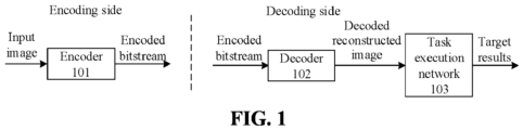
- FIG. 1 is a schematic diagram of an overall framework provided by an embodiment of the present disclosure.
- the overall framework includes an encoder 101, a decoder 102, and a task execution network 103.
- the encoder 101 belongs to an encoding side device, the decoder 102 and the task execution network 103 belong to an decoding side device, and the encoding side device and the decoding side device exchange information by establishing a wireless connection.
- the encoder 101 encodes an input image to obtain an encoded bitstream.
- the encoded bitstream is wirelessly transmitted to the decoding side device, and the decoder 102 decodes the encoded bitstream to obtain a decoded reconstructed image.
- the task execution network 103 performs a machine learning task based on the decoded reconstructed image to obtain target results.
- the encoding side device may also have a decoder, and the decoding side device may also have an encoder.
- FIG. 2 is a schematic diagram of an overall framework provided by an embodiment of the present disclosure.
- the overall framework includes an image pre-processing module 201, an encoder 101, a decoder 102, an image post-processing module 202 and a task execution network 103.
- the image pre-processing module 201 and the encoder 101 belong to an encoding side device
- the decoder 102, the image post-processing module 202 and the task execution network 103 belong to a decoding side device
- the encoding side device and the decoding side device exchange information by establishing a wireless connection.
- the image pre-processing module 201 pre-processes the input image and sends the input image subjected to pre-processing to the encoder 101, and the encoder 101 encodes the input image subjected to pre-processing to obtain an encoded bitstream.
- the encoded bitstream is wirelessly transmitted to the decoding side device, and the decoder 102 decodes the encoded bitstream to obtain a decoded reconstructed image.
- the image post-processing module 202 (symmetrical to the image pre-processing module 201) performs image post-processing on the decoded reconstructed image to obtain a decoded reconstructed image subjected to image post-processing.
- the task execution network 103 performs a machine learning task based on the decoded reconstructed image subjected to image post-processing to obtain target results.
- FIG. 3 is an implementation flowchart of a network training method of an embodiment of the present disclosure. As illustrated in FIG. 3 , the method may include the following operations 301 to 303.
- a preset sample training set is obtained.
- a joint loss function of a codec network and a task execution network is determined.
- the task execution network performs a machine learning task based on a decoded reconstructed image output from the codec network, and the joint loss function includes a loss function of the task execution network and a function representing a bitrate of a feature bitstream of an input image of the codec network.
- a network structure of the codec network may be any neural network structure which is not limited in the embodiment of the present disclosure.
- the codec network is a cheng2020 network, that is, a network pointed out by " Cheng Z, Sun H, Takeuchi M, et al. Learned image compression with discretized gaussian mixture likelihoods and attention modules[C]//Proceedings of the IEEE/CVF Conference on Computer Vision and Pattern Recognition. 2020: 7939-7948 ".
- a network structure of the task execution network is not limited, and can be any machine learning model.
- the task execution network is a Faster RCNN X101-FPN target detection network in Facebook Research Institute's open source detector 2, that is, a target detection network pointed out by " Yuxin Wu and Alexander Kirillov and Francisco Massa and Wan-Yen Lo and Ross Girshick. Detectron2. [OL] https://github.com/facebookresearch/detectron2. 2019 ".
- the task execution network performs a segmentation task, a classification task or an identification task in industry.
- joint training is performed on the codec network and the task execution network until a value of the joint loss function meets a convergence condition, to obtain a trained codec network and a trained task execution network.
- network parameters of the codec network and the task execution network are adjusted based on the value of the joint loss function which is determined based on results of an current input image passing through both the codec network and the task execution network, thereby realizing a joint training.
- the codec network includes an encoder and a decoder, and each of the encoder and the decoder has a neural network structure.
- the function of the codec network and the function of the task execution network can be performed on the same device or on different devices.
- the encoded bitstream output from the encoder can be transmitted to the decoder through an analog channel, and a device used for performing network training (hereinafter referred to as training device) and a device where the codec network is located can also be the same device or can be different devices.
- the training device can obtain results output from the encoder, the decoder and the task execution network, and determine a value of the joint loss function of this training based on the obtained results and the sample data used in this training.
- the encoder is implemented on the encoding side device
- the decoder and the task execution network are implemented on the decoding side device
- the encoding side device and the decoding side device are different devices.
- the training device can be the encoding side device, the decoding side device or the third party device.
- the training device can obtain the results output from the encoder, the decoder and the task execution network, and determine a value of the joint loss function of this training based on the obtained results and the sample data used in this training.
- joint training of the codec network and the task execution network is performed, and the joint loss function used for the joint training includes: a loss function of the task execution network and a function representing a bitrate of a feature bitstream of an input image of the codec network. In this way, under the constraint of a certain bitrate, it enables the task execution network to achieve better performance when performing the machine learning task on the decoded reconstructed image.
- the joint loss function further includes a loss function representing differences between the input image of the codec network and the decoded reconstructed image that is output from the codec network and corresponds to the input image.
- the joint loss function further includes a function representing a bitrate of a bitrate estimation bitstream.
- the joint loss function is a sum of all the functions included in the joint loss function.
- the loss function of the task execution network is given a first weight, and the loss function representing the differences is given a second weight.
- the codec network includes an encoder and a decoder.
- An obtaining process of the decoded reconstructed image includes the following operations.
- An encoded bitstream is received.
- the encoded bitstream is obtained by encoding, by the encoder, the input image or the input image subjected to pre-processing.
- a decoded reconstructed image is obtained by decoding, by the decoder, the encoded bitstream.
- each of the encoder and the decoder has a neural network structure.
- an embodiment of the present disclosure further provides an overall framework.
- FIG. 4 is a schematic diagram of an overall framework provided by an embodiment of the present disclosure. As illustrated in FIG. 4 , the overall framework includes an image pre-processing module 201, an encoder 101, a decoder 102, an image post-processing module 202 and a task execution network 103.
- the encoder 101 includes a first neural network convolutional layer 1011, a quantization unit 1012 and an entropy encoding unit 1013.
- the decoder 102 includes an entropy decoding unit 1021, an inverse quantization unit 1022 and a second neural network convolutional layer 1023.
- a workflow of the overall framework includes the followings.
- the image pre-processing module 201 pre-processes an input image and sends the input image subjected to pre-processing to the first neural network convolutional layer 1011.
- the first neural network convolutional layer 1011 performs analysis transform of the input image subjected to pre-processing to obtain features of the input image.
- the quantization unit 1012 quantizes the features of the input image and inputs the quantized features of the input image to the entropy encoding unit 1013, the entropy encoding unit 1013 performs entropy encoding of the quantized features of the input image to obtain the encoded bitstream.
- the encoded bitstream includes a bitrate estimation bitstream and a feature bitstream of the input image.
- the encoded bitstream is received, and the entropy decoding unit 1021 performs entropy decoding of the feature bitstream based on the bitrate estimation bitstream to obtain entropy decoding results.
- the inverse quantization unit 1022 inversely quantizes the entropy decoding results and inputs the entropy decoding results subjected to inverse quantization to a second neural network convolutional layer 1023.
- the second neural network convolutional layer 1023 performs synthetic transform of the entropy decoding results subjected to inverse quantization to obtain the decoded reconstructed image.
- the image post-processing module 202 performs image post-processing (corresponding to pre-processing at the encoding side) on the decoded reconstructed image and sends the post-processed decoded reconstructed image to the task execution network 103.
- the task execution network 103 performs a machine learning task based on the decoded reconstructed image subjected to image post-processing to obtain target results.
- the image pre-processing module 201 and the image post-processing module 202 are optional. That is, the overall framework illustrated in FIG. 4 may not include the image pre-processing module 201 and the image post-processing module 202. Accordingly, at the encoding side, the first neural network convolutional layer 1011 performs analysis transform of the un-preprocessed input image to obtain features of the input image. At the decoding side, the task execution network 103 performs a machine learning task based on the decoded reconstructed image that is un-preprocessed to obtain target results.
- the inverse quantization unit 1022 is also optional. That is, the overall framework illustrated in FIG. 4 may not include the inverse quantization unit 1022, and accordingly, the second neural network convolutional layer 1023 performs synthetic transform of the entropy decoding results that are not inversely quantized, to obtain a decoded reconstructed image.
- an embodiment of the present disclosure provides an encoding method which is applied to the encoding side.
- the method includes the following operations.
- An input image is encoded by a trained encoder to obtain an encoded bitstream.
- the trained encoder and the trained decoder belong to a trained codec network, and the trained codec network and the trained task execution network are obtained according to the network training method described in the embodiments of the present disclosure.
- the encoded bitstream includes a bitrate estimation bitstream and a feature bitstream of the input image
- the trained encoder has a neural network structure.
- the operation of encoding the input image by the trained encoder to obtain the encoded bitstream includes following operations. Analysis transform is performed, by a first neural network convolutional layer, on the input image or the input image subjected to pre-processing to obtain features of the input image. The features of the input image are quantized, and then the entropy encoding is performed on the quantized features of the input image, to obtain the bitrate estimation bitstream and the feature bitstream of the input image.
- the input image can be a video frame image in a video or a certain image in a group of images. There is no limitation on what kind of visual media content the input image is.
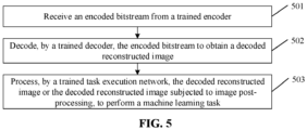
- FIG. 5 is an implementation flowchart of an image processing method of an embodiment of the present disclosure, and the method may include the following operations 501 to 503.
- an encoded bitstream is received from a trained encoder.
- the encoded bitstream is decoded by a trained decoder to obtain a decoded reconstructed image.
- the encoded bitstream includes a bitrate estimation bitstream and a feature bitstream of the input image
- the trained decoder has a neural network structure.
- the decoding side performs, based on the bitrate estimation bitstream, entropy decoding of the feature bitstream to obtain entropy decoding results.
- the second neural network convolutional layer performs synthetic transform of the entropy decoding results or the entropy decoding results subjected to inverse quantization to obtain the decoded reconstructed image.
- the decoded reconstructed image or the decoded reconstructed image subjected to image post-processing is processed by a trained task execution network to perform a machine learning task.
- the trained encoder and the trained decoder belong to a trained codec network, and the trained codec network and the trained task execution network are obtained according to the network training method described in the embodiments of the present disclosure.
- the input image is directly encoded by a codec to generate a bitstream, and the bitstream is transmitted to the decoding side, then the bitstream is decoded at the decoding side to obtain a decoded reconstructed image, and then an intelligent task (i.e., machine learning task) is performed based on the decoded reconstructed image.
- an intelligent task i.e., machine learning task
- the relevant codec is not specifically optimized for the intelligent task, and redundant information that is not related to the intelligent task cannot be effectively deleted.
- an image end-to-end encoding network oriented to the intelligent task is provided, and the object is to achieve optimal performance when performing the intelligent task on the decoded reconstructed image subjected to decoding in a case that bitstream transmission is constrained by a certain bitrate.
- FIG. 6 An overall framework of an embodiment of the present disclosure is illustrated in FIG. 6 , in which image pre-processing is performed on (or not performed on) an original data set (i.e., the input image) and then the pre-processed original data set is sent to the encoder 101 for encoding and outputs an encoded bitstream, the encoded bitstream is sent to the decoder 102 for decoding, and followed by performing the image post-processing (corresponding to the pre-processing at the encoding side) to output a compressed image, i.e., a compressed data set, and the compressed data set is processed for the intelligent task to output results.
- the codec herein uses a neural network structure. As illustrated in FIG.
- an analysis transform is performed on an uncompressed image by the first neural network convolutional layer, and the output features are quantized and sent to the entropy encoder for entropy encoding.
- the decoding side obtains the transmitted bitstream and then performs entropy decoding of the obtained bitstream. Additional bitrate estimation is required to be performed at the encoding side, and the bitstream information related to the bitrate estimation is transmitted to the decoding side, and then the decoded features are input to the second neural network convolutional layer for synthetic transform, and finally a compressed image (i.e., decoded reconstructed image) is reconstructed.
- the bitstream includes a feature bitstream and a bitrate estimation bitstream.
- the feature bitstream refers to features of an image output through a neural network convolutional layer
- the bitrate estimation bitstream refers to a related parameter carrying the feature bitrate estimation probability.
- R( ⁇ ) is a function of a bitrate of feature expression (the feature bitstream in FIG. 7 )
- R( ⁇ ) is a function of a bitrate of side information (the bitrate estimation bitstream in FIG.
- ⁇ 1 and ⁇ 2 represent rate-distortion trade-off parameters (i.e., the first weight and the second weight), different parameters ⁇ 1 and ⁇ 2 correspond to different models (i.e., different total bitrates), loss task refers to an intelligent task loss, and D ( x, x ⁇ ) refers to a distortion loss between the input image and the decoded reconstructed image.
- the cheng2020 network is used as the codec network
- the Faster RCNN X101-FPN target detection network in Facebook Research Institute's open source detector 2 is used as the intelligent task network
- an VTM (Versatile Video Coding Test Model) 8.2 encoder is used as an anchor for performance comparison.
- the D ( x, x ⁇ ) specifically uses mean square error as distortion
- loss task uses a loss function of target detection in Faster RCNN X101-FPN as a loss
- the function is illustrated in a Formula (6):
- loss task L cls + L box
- L cls L cls p ⁇
- u i ⁇ i ⁇ ⁇ I ⁇ logp u i , i
- L box ⁇ f u L box t u
- L cls is a loss of classification
- L box refers to a loss of target box position
- I refers to a total number of regions of interest output from the network
- i refers to an index of the region of interest.
- the ⁇ refers to a case in which there is a probability of a real class in prediction of the i-th region of interest
- u i refers to that the i-th region of interest is the real class.
- the p(u, i) in a Formula (7) refers to a network estimation probability of the i-th region of interest belonging to the u-th class.
- t j u refers to relative offsets between a regression box which is predicted to be belonging to the real class and the anchor regression box in the network
- t u t x u t y u t w u t h u
- t x x ⁇ x a w a
- t y y ⁇ y a h a
- t w log w w a
- t h log h h a
- x refers to an x coordinate of an upper left vertex of the predicted regression box
- y refers to a y coordinate of the upper left vertex of the predicted regression box
- w refers to a width w of the predicted regression box
- h refers to a length h of the predicted regression box
- x a , y a , w a and h a represent four parameters of the anchor regression box
- v j refers to four
- Test results are illustrated in Table 1, Table 2 and Table 3 below.
- the Table 1 illustrates task performance of an anchor compressed by using VTM8.2.
- the Table 2 illustrates evaluation results of a predefined task network (faster R-CNN X101-FPN in Detecton2) with end-to-end image encoding input consistent with an anchor point. There is an optimized cheng2020 network, and network parameter bitrate points are all 6 points.
- the Table 3 illustrates performance comparison between the technical solution provided by the embodiment of the present disclosure and the anchor point in a target detection task.
- the test results of this solution illustrate that the performance of the end-to-end compression method of joint training of the codec and intelligent task provided by the embodiment of the present disclosure is better than that of the anchor.
- r H log( BPP H ) is the highest point of bits per pixel of the output bitstream
- r L log( BPP L ) is the lowest point of bits per pixel of the output bitstream
- D 2 ( r ) and D 1 ( r ) are respectively two R-D curves
- D H is the highest point of distortion corresponding to the output bitstream
- D L is the lowest point of distortion corresponding to the output bitstream
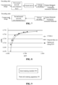
- the performance of the technical solution provided by the embodiment of the present disclosure is superior to the performance of the anchor, as illustrated in the Table 3, the BD-BPP (mAP) is -22.80% and the BD-mAP is -1.0184, which is the beneficial effect generated by the technical solution of the embodiment of the present disclosure.
- Performance of target detection task (optimized cheng2020 codec) Parameter BPP mAP 1 0.5556372957 0.76346890 2 0.4531612348 0.76153704 3 0.3147077104 0.75533322 4 0.1958046374 0.74696396 5 0.1167023101 0.72394438 6 0.0746458029 0.70362475 Tabl33. Performance comparison of "optimized cheng2020" and anchor VTM8.2, optimized cheng2020 BD-BPP(mAP) 29.54% -22.80% BD-mAP 1.0184 -1.0184
- Figure 8 illustrates the performance comparison between the VTM 8.2 codec and the optimized Cheng 2020 network.
- the codec network and the intelligent task network are jointly trained, and a new loss function oriented to the intelligent task is proposed, so that redundant information that is not related to the intelligent task can be removed, thereby improving the performance of the intelligent task.
- an embodiment of the present disclosure provides a network training apparatus, an image processing apparatus and an encoding apparatus, various modules included in these apparatuses and various units included in each module can be implemented by a processor.
- the modules included in these apparatuses and the units included in each module can also be implemented by specific logic circuits.
- the processor may be a central processing unit (CPU), a microprocessor (MPU), a digital signal processor (DSP), a field programmable gate array (FPGA), etc.
- FIG. 9 is a schematic structural diagram of a network training apparatus of an embodiment of the present disclosure.
- a network training apparatus 90 includes a joint training module 901, configured to: perform, based on a joint loss function of a codec network and a task execution network, and a preset sample training set, joint training of the codec network and the task execution network until a value of the joint loss function meets a convergence condition, to obtain a trained codec network and a trained task execution network.
- the task execution network performs a machine learning task based on a decoded reconstructed image output from the codec network, and the joint loss function includes a loss function of the task execution network and a function representing a bitrate of a feature bitstream of an input image of the codec network.
- the joint loss function further includes a loss function representing differences between the input image of the codec network and the decoded reconstructed image that is output from the codec network and corresponds to the input image.
- the joint loss function further includes a function representing a bitrate of a bitrate estimation bitstream.
- the joint loss function is a sum of the functions included in the joint loss function.
- the loss function of the task execution network is given a first weight, and the loss function representing the differences is given a second weight.
- the codec network includes an encoder and a decoder.
- the network training apparatus 90 further includes a receiving module and a decoding module.
- the receiving module is configured to receive an encoded bitstream.
- the encoded bitstream is obtained by encoding, by the encoder, the input image or the input image subjected to pre-processing.
- the decoding module is configured to decode, by the decoder, the encoded bitstream to obtain a decoded reconstructed image.
- each of the encoder and the decoder has a neural network structure.
- the obtaining process of the encoded bitstream includes the following operations. Analysis transform is performed, by a first neural network convolutional layer, on the input image or the input image subjected to pre-processing to obtain features of the input image. The features of the input image are quantized, and then the entropy encoding is performed on the quantized features of the input image to obtain the encoded bitstream.
- the encoded bitstream includes the bitrate estimation bitstream and the feature bitstream of the input image.
- the decoding module is configured to: perform, based on the bitrate estimation bitstream, entropy decoding of the feature bitstream to obtain entropy decoding results; and perform, by a second neural network convolutional layer, synthetic transform of the entropy decoding results or the entropy decoding results subjected to inverse quantization to obtain the decoded reconstructed image.
- FIG. 10 is a schematic structural diagram of an image processing apparatus provided by an embodiment of the present disclosure.
- the image processing apparatus 100 includes a receiving module 1001, a decoding module 1002 and an image processing module 1003.
- the receiving module 1001 is configured to receive an encoded bitstream from a trained encoder.
- the decoding module 1002 is configured to decode, by a trained decoder, the encoded bitstream to obtain a decoded reconstructed image.
- the image processing module 1003 is configured to process, by a trained task execution network, the decoded reconstructed image, to perform a machine learning task.
- the trained encoder and the trained decoder belong to a trained codec network, and the trained codec network and the trained task execution network are obtained according to the network training method described in the embodiments of the present disclosure.
- the encoded bitstream includes a bitrate estimation bitstream and a feature bitstream of the input image
- the trained decoder has a neural network structure.
- the decoding module 1002 is configured to perform, based on the bitrate estimation bitstream, entropy decoding of the feature bitstream to obtain entropy decoding results; and perform, by a second neural network convolutional layer, synthetic transform of the entropy decoding results or the entropy decoding results subjected to inverse quantization to obtain the decoded reconstructed image.
- FIG. 11 is a schematic structural diagram of an encoding apparatus provided by an embodiment of the present disclosure.
- the encoding apparatus 110 includes an encoding module 111.
- the encoding module 111 is configured to encode, by a trained encoder, an input image to obtain an encoded bitstream.
- the trained encoder belongs to a trained codec network that is obtained according to the network training method described in the embodiments of the present disclosure.
- the encoded bitstream includes a bitrate estimation bitstream and a feature bitstream of the input image
- the trained encoder has a neural network structure.
- the encoding module 111 is configured to perform, by a first neural network convolutional layer, analysis transform of the input image or the input image subjected to pre-processing to obtain features of the input image; and quantize the features of the input image and then perform entropy encoding of the quantized features of the input image, to obtain the bitrate estimation bitstream and the feature bitstream of the input image.
- the division of the modules by the apparatus in the embodiments of the present disclosure is illustrative and is only the division of logical functions, and there can be another division mode in actual implementation.
- the functional units in various embodiments of the present disclosure may be integrated in one processing unit, may be physically present alone, or may have two or more units integrated in one unit.
- the integrated unit can be realized either in the form of hardware or in the form of software functional unit. It can also be realized by combining software and the hardware.
- the method can also be stored in a computer-readable storage medium.
- the technical solutions of the embodiments of the present disclosure substantially or parts making contributions to the related arts may be embodied in form of software product, and the computer software product is stored in a storage medium, including several instructions configured to enable an electronic device (e.g., the electronic device may include various types of devices capable of processing information, such as personal computers, notebook computers or cluster servers) to perform all or part of the methods described in the various embodiments of the present disclosure.
- the foregoing storage media includes various media capable of storing program codes, such as U disk, mobile hard disk, Read Only Memory (ROM), magnetic disk or optical disk.
- the embodiments of the present disclosure are not limited to any particular combination of the hardware and the software.
- FIG. 12 is a diagram of a hardware entity of an electronic device of an embodiment of the present disclosure.
- the electronic device 120 includes a memory 121 and a processor 122.
- the memory 121 stores a computer program executable on the processor 122, and the processor 122 implements the operations in the method provided in the embodiments of the present disclosure when executing the computer program.
- the memory 121 is configured to store instructions and applications executable by the processor 122, and may also cache data (e.g., image data, audio data, voice communication data and video communication data) to be processed or already processed by modules in the processor 122 and the electronic device 120.
- the memory 121 may be implemented by a Flash memory or a Random Access Memory (RAM).
- An embodiment of the present disclosure provides a computer-readable storage medium, having stored thereon a computer program that, when being executed by a processor, implements the operations in the method provided in the embodiments of the present disclosure.
- An embodiment of the present disclosure provides a computer program product including instructions that, when run on a computer, cause the computer to perform the operations in the method provided by the method embodiments of the present disclosure.
- object A and/or object B may have three meanings: the object A exists alone, the object A and the object B exist at the same time, and the object B exists alone.
- the disclosed device and method may be implemented in other ways.
- the above-described embodiments are only illustrative.
- the division of the modules is only the division of logical functions, and there can be another division mode in actual implementation.
- multiple modules or components can be combined, or can be integrated into another system, or some features can be ignored or not implemented.
- coupling, direct coupling, or communication connection between various components that are illustrated or discussed may be implemented through some interfaces, and the indirect coupling or communication connection between the devices or modules may be electrical, mechanical, or in other forms.
- modules described above as separate components may or may not be physically separated and the components represented as modules may or may not be physical modules. That is, the modules may be located in one location or distributed on multiple network units. Some or all of the modules may be selected based on the actual needs to achieve the purpose of the solutions of the embodiment.
- each functional module in each embodiment of the present disclosure may all be integrated into a processing unit, each module may serve as an independent unit, and two or more than two modules can be integrated into a unit.
- the integrated modules may be implemented either in the form of hardware or in the form of hardware and software functional units.
- the storage medium includes various media capable of storing program codes, such as a mobile storage device, a ROM, a magnetic disk or a compact disc.
- the integrated unit of the present disclosure may also be stored in a computer-readable storage medium.
- the technical solutions of the embodiments of the present disclosure substantially or parts making contributions to the related arts may be embodied in form of a software product, and the computer software product is stored in a storage medium, including a plurality of instructions configured to enable an electronic device to execute all or part of the method in each embodiment of the present disclosure.
- the storage medium includes various media capable of storing program codes, such as a mobile storage device, a ROM, a magnetic disk or a compact disc.
Landscapes
- Engineering & Computer Science (AREA)
- Theoretical Computer Science (AREA)
- Physics & Mathematics (AREA)
- Evolutionary Computation (AREA)
- Multimedia (AREA)
- Computing Systems (AREA)
- General Physics & Mathematics (AREA)
- Signal Processing (AREA)
- Health & Medical Sciences (AREA)
- Software Systems (AREA)
- General Health & Medical Sciences (AREA)
- Artificial Intelligence (AREA)
- Data Mining & Analysis (AREA)
- General Engineering & Computer Science (AREA)
- Biophysics (AREA)
- Mathematical Physics (AREA)
- Biomedical Technology (AREA)
- Life Sciences & Earth Sciences (AREA)
- Molecular Biology (AREA)
- Computational Linguistics (AREA)
- Computer Vision & Pattern Recognition (AREA)
- Databases & Information Systems (AREA)
- Medical Informatics (AREA)
- Image Analysis (AREA)
- Compression Or Coding Systems Of Tv Signals (AREA)
Abstract
Description
- This application is based upon and claims priority to
Chinese patent application No. 202110415028.1 filed on April 17, 2021 - Embodiments of the present disclosure relate to image technologies, and relate to, but are not limited to, an image processing method, a network training method, an encoding method, an encoding apparatus, a device and a storage medium.
- In related arts, an input image is encoded by an encoder at an encoding side, and an encoded bitstream is generated and transmitted to a decoding side; the encoded bitstream is decoded at the decoding side to obtain a decoded reconstructed image; and finally, a machine learning task is performed based on the decoded reconstructed image.
- In view of this, an image processing method, a network training method, an encoding method, an encoding apparatus, a device and a storage medium provided by embodiments of the present disclosure are implemented as follows.
- The network training method provided by an embodiment of the present disclosure includes the following operations. Based on a joint loss function of a codec network and a task execution network and a preset sample training set, joint training of the codec network and the task execution network is performed until a value of the joint loss function meets a convergence condition, to obtain a trained codec network and a trained task execution network. The task execution network performs a machine learning task based on a decoded reconstructed image output from the codec network, and the joint loss function includes a loss function of the task execution network and a function representing a bitrate of a feature bitstream of an input image of the codec network.
- The image processing method provided by an embodiment of the present disclosure includes the following operations. An encoded bitstream is received from a trained encoder. The encoded bitstream is decoded by a trained decoder to obtain a decoded reconstructed image. The decoded reconstructed image or the decoded reconstructed image subjected to image post-processing is processed by a trained task execution network to perform or complete a machine learning task. The trained encoder and the trained decoder belong to a trained codec network obtained according to the network training method described in the embodiment of the present disclosure.
- The encoding method provided by an embodiment of the present disclosure includes the following operations. An input image is encoded by a trained encoder to obtain an encoded bitstream. The trained encoder belongs to a trained codec network that is obtained according to the network training method described in the embodiment of the present disclosure.
- The network training apparatus provided by an embodiment of the present disclosure includes a joint training module. The joint training module is configured to: perform, based on a joint loss function of a codec network and a task execution network and a preset sample training set, joint training of the codec network and the task execution network until a value of the joint loss function meets a convergence condition, to obtain a trained codec network and a trained task execution network. The task execution network performs a machine learning task based on a decoded reconstructed image output from the codec network, and the joint loss function includes a loss function of the task execution network and a function representing a bitrate of a feature bitstream of an input image of the codec network.
- The image processing apparatus provided by an embodiment of the present disclosure includes: a receiving module, a decoding module and an image processing module. The receiving module is configured to receive an encoded bitstream from a trained encoder. The decoding module is configured to decode, by a trained decoder, the encoded bitstream to obtain a decoded reconstructed image. The image processing module is configured to process, by a trained task execution network, the decoded reconstructed image, to perform a machine learning task. The trained encoder and the trained decoder belong to a trained codec network, and the trained codec network and the trained task execution network are obtained according to the network training method described in the embodiment of the present disclosure.
- The encoding apparatus provided by an embodiment of the present disclosure includes an encoding module. The encoding module is configured to encode, by a trained encoder, an input image to obtain an encoded bitstream. The trained encoder belongs to a trained codec network that is obtained according to the network training method described in the embodiment of the present disclosure.
- An electronic device provided by an embodiment of the present disclosure includes a memory and a processor. The memory stores a computer program executable on the processor that, when executing the program, implements the network training method described in the embodiment of the present disclosure, the image processing method described in the embodiment of the present disclosure, or the encoding method described in the embodiment of the present disclosure.
- An computer-readable storage medium, having stored thereon a computer program that, when being executed by a processor, implements the network training method described in the embodiment of the present disclosure, the image processing method described in the embodiment of the present disclosure, or the encoding method described in the embodiment of the present disclosure.
- The accompanying drawings, which are incorporated in and constitute a part of the specification, illustrate embodiments consistent with the present disclosure and together with the specification serve to explain the technical solutions of the present disclosure.
-
FIG. 1 is a schematic diagram of an overall framework provided by an embodiment of the present disclosure. -
FIG. 2 is a schematic diagram of an overall framework provided by another embodiment of the present disclosure. -
FIG. 3 is an implementation flowchart of a network training method of an embodiment of the present disclosure. -
FIG. 4 is a schematic diagram of an overall framework provided by an embodiment of the present disclosure. -
FIG. 5 is an implementation flowchart of an image processing method of an embodiment of the present disclosure. -
FIG. 6 is a schematic diagram of an overall framework provided by yet another embodiment of the present disclosure. -
FIG. 7 is a workflow diagram of a codec provided by an embodiment of the present disclosure. -
FIG. 8 is a schematic diagram of performance comparison between VTM 8.2 codec and optimized cheng2020 network. -
FIG. 9 is a schematic structural diagram of a network training apparatus of an embodiment of the present disclosure. -
FIG. 10 is a schematic structural diagram of an image processing apparatus provided by an embodiment of the present disclosure. -
FIG. 11 is a schematic structural diagram of an encoding apparatus provided by an embodiment of the present disclosure. -
FIG. 12 is a schematic structural diagram of an electronic device provided by an embodiment of the present disclosure. - In order to make the purpose, technical solutions and advantages of the embodiments of the present disclosure clearer, the specific technical solutions of the present disclosure will be further described in detail with reference to the drawings in the embodiments of the present disclosure. The following embodiments are used to illustrate the present disclosure, but are not intended to limit the scope of the present disclosure.
- Unless otherwise defined, all technical and scientific terms used herein have the same meaning as would normally be understood by those skilled in the art of the present disclosure. The terminology used herein is for the purpose of describing the embodiments of the present disclosure only and is not intended to limit the present disclosure.
- The phrase "some embodiments" referred to in the following description describes a subset of all possible embodiments. However, it is understood that "some embodiments" may be the same subset or different subsets of all possible embodiments and may be combined with each other without conflict.
- It should be noted that the term "first\second\third" referred to in the embodiments of the present disclosure is used to distinguish between similar or different objects and does not represent a particular order for objects. It should be understood that "first\second\third" may be interchanged in a particular order or sequencing where permissible to enable the embodiments of the present disclosure described herein to be implemented in an order other than that illustrated or described herein.
- The overall framework and the business scenario described in the embodiments of the present disclosure are intended to more clearly explain the technical solutions of the embodiments of the present disclosure, and do not constitute a limitation to the technical solutions provided by the embodiments of the present disclosure. As those of ordinary skill in the art will know, with the evolution of the overall framework and the emergence of new business scenarios, the technical solutions provided by the embodiments of the present disclosure are equally applicable to similar technical problems.
-
FIG. 1 is a schematic diagram of an overall framework provided by an embodiment of the present disclosure. As illustrated inFIG. 1 , the overall framework includes anencoder 101, adecoder 102, and atask execution network 103. Theencoder 101 belongs to an encoding side device, thedecoder 102 and thetask execution network 103 belong to an decoding side device, and the encoding side device and the decoding side device exchange information by establishing a wireless connection. Theencoder 101 encodes an input image to obtain an encoded bitstream. The encoded bitstream is wirelessly transmitted to the decoding side device, and thedecoder 102 decodes the encoded bitstream to obtain a decoded reconstructed image. Thetask execution network 103 performs a machine learning task based on the decoded reconstructed image to obtain target results. - It should be noted that the encoding side device may also have a decoder, and the decoding side device may also have an encoder.
-
FIG. 2 is a schematic diagram of an overall framework provided by an embodiment of the present disclosure. As illustrated inFIG. 2 , the overall framework includes animage pre-processing module 201, anencoder 101, adecoder 102, animage post-processing module 202 and atask execution network 103. Theimage pre-processing module 201 and theencoder 101 belong to an encoding side device, and thedecoder 102, theimage post-processing module 202 and thetask execution network 103 belong to a decoding side device, and the encoding side device and the decoding side device exchange information by establishing a wireless connection. Theimage pre-processing module 201 pre-processes the input image and sends the input image subjected to pre-processing to theencoder 101, and theencoder 101 encodes the input image subjected to pre-processing to obtain an encoded bitstream. The encoded bitstream is wirelessly transmitted to the decoding side device, and thedecoder 102 decodes the encoded bitstream to obtain a decoded reconstructed image. The image post-processing module 202 (symmetrical to the image pre-processing module 201) performs image post-processing on the decoded reconstructed image to obtain a decoded reconstructed image subjected to image post-processing. Thetask execution network 103 performs a machine learning task based on the decoded reconstructed image subjected to image post-processing to obtain target results. - An embodiment of the present disclosure firstly provides a network training method.
FIG. 3 is an implementation flowchart of a network training method of an embodiment of the present disclosure. As illustrated inFIG. 3 , the method may include the followingoperations 301 to 303. - In an
operation 301, a preset sample training set is obtained. - In an
operation 302, a joint loss function of a codec network and a task execution network is determined. The task execution network performs a machine learning task based on a decoded reconstructed image output from the codec network, and the joint loss function includes a loss function of the task execution network and a function representing a bitrate of a feature bitstream of an input image of the codec network. - It should be noted that a network structure of the codec network may be any neural network structure which is not limited in the embodiment of the present disclosure. For example, the codec network is a cheng2020 network, that is, a network pointed out by "Cheng Z, Sun H, Takeuchi M, et al. Learned image compression with discretized gaussian mixture likelihoods and attention modules[C]//Proceedings of the IEEE/CVF Conference on Computer Vision and Pattern Recognition. 2020: 7939-7948".
- Similarly, a network structure of the task execution network is not limited, and can be any machine learning model. For example, the task execution network is a Faster RCNN X101-FPN target detection network in Facebook Research Institute's open source detector 2, that is, a target detection network pointed out by "Yuxin Wu and Alexander Kirillov and Francisco Massa and Wan-Yen Lo and Ross Girshick. Detectron2. [OL] https://github.com/facebookresearch/detectron2. 2019".
- There is no limitation on the task performed by the task execution network. For example, the task execution network performs a segmentation task, a classification task or an identification task in industry.
- In an
operation 303, based on the joint loss function and the preset sample training set, joint training is performed on the codec network and the task execution network until a value of the joint loss function meets a convergence condition, to obtain a trained codec network and a trained task execution network. - Understandably, network parameters of the codec network and the task execution network are adjusted based on the value of the joint loss function which is determined based on results of an current input image passing through both the codec network and the task execution network, thereby realizing a joint training.
- The codec network includes an encoder and a decoder, and each of the encoder and the decoder has a neural network structure. The function of the codec network and the function of the task execution network can be performed on the same device or on different devices. When the functions are performed on the same device, the encoded bitstream output from the encoder can be transmitted to the decoder through an analog channel, and a device used for performing network training (hereinafter referred to as training device) and a device where the codec network is located can also be the same device or can be different devices. When the training device and the device where the codec network is located are different devices, the training device can obtain results output from the encoder, the decoder and the task execution network, and determine a value of the joint loss function of this training based on the obtained results and the sample data used in this training.
- When the function of the codec network and the function of the task execution network are executed on different devices, i.e., the encoder is implemented on the encoding side device, the decoder and the task execution network are implemented on the decoding side device, the encoding side device and the decoding side device are different devices. The training device can be the encoding side device, the decoding side device or the third party device. The training device can obtain the results output from the encoder, the decoder and the task execution network, and determine a value of the joint loss function of this training based on the obtained results and the sample data used in this training.
- After analysis, it is found that there is no special optimization for the machine learning task in the related arts, thus, the redundant information that is not related to the machine learning task cannot be effectively deleted and removed. However, in the embodiments of the present disclosure, joint training of the codec network and the task execution network is performed, and the joint loss function used for the joint training includes: a loss function of the task execution network and a function representing a bitrate of a feature bitstream of an input image of the codec network. In this way, under the constraint of a certain bitrate, it enables the task execution network to achieve better performance when performing the machine learning task on the decoded reconstructed image.
- In some embodiments, the joint loss function further includes a loss function representing differences between the input image of the codec network and the decoded reconstructed image that is output from the codec network and corresponds to the input image.
- In some embodiments, the joint loss function further includes a function representing a bitrate of a bitrate estimation bitstream.
- In some embodiments, the joint loss function is a sum of all the functions included in the joint loss function. The loss function of the task execution network is given a first weight, and the loss function representing the differences is given a second weight.
- For example, as illustrated in a Formula (1), in some embodiments, the expression of the joint loss function may be:

- As another example, as illustrated in a Formula (2), in some embodiments, the expression of the joint loss function may be:

- For another example, as illustrated a Formula (3), in some embodiments, the expression of the joint loss function may be:

- As another example, as illustrated in a Formula (4), in some embodiments, the expression of the joint loss function may be:

- In some embodiments, the codec network includes an encoder and a decoder. An obtaining process of the decoded reconstructed image includes the following operations. An encoded bitstream is received. The encoded bitstream is obtained by encoding, by the encoder, the input image or the input image subjected to pre-processing. A decoded reconstructed image is obtained by decoding, by the decoder, the encoded bitstream.
- In some embodiments, each of the encoder and the decoder has a neural network structure. In addition, an embodiment of the present disclosure further provides an overall framework.
FIG. 4 is a schematic diagram of an overall framework provided by an embodiment of the present disclosure. As illustrated inFIG. 4 , the overall framework includes animage pre-processing module 201, anencoder 101, adecoder 102, animage post-processing module 202 and atask execution network 103. Theencoder 101 includes a first neural network convolutional layer 1011, aquantization unit 1012 and anentropy encoding unit 1013. Thedecoder 102 includes anentropy decoding unit 1021, aninverse quantization unit 1022 and a second neuralnetwork convolutional layer 1023. - A workflow of the overall framework includes the followings. At an encoding side, the
image pre-processing module 201 pre-processes an input image and sends the input image subjected to pre-processing to the first neural network convolutional layer 1011. The first neural network convolutional layer 1011 performs analysis transform of the input image subjected to pre-processing to obtain features of the input image. Thequantization unit 1012 quantizes the features of the input image and inputs the quantized features of the input image to theentropy encoding unit 1013, theentropy encoding unit 1013 performs entropy encoding of the quantized features of the input image to obtain the encoded bitstream. The encoded bitstream includes a bitrate estimation bitstream and a feature bitstream of the input image. - At a decoding side, the encoded bitstream is received, and the
entropy decoding unit 1021 performs entropy decoding of the feature bitstream based on the bitrate estimation bitstream to obtain entropy decoding results. Theinverse quantization unit 1022 inversely quantizes the entropy decoding results and inputs the entropy decoding results subjected to inverse quantization to a second neuralnetwork convolutional layer 1023. The second neuralnetwork convolutional layer 1023 performs synthetic transform of the entropy decoding results subjected to inverse quantization to obtain the decoded reconstructed image. Theimage post-processing module 202 performs image post-processing (corresponding to pre-processing at the encoding side) on the decoded reconstructed image and sends the post-processed decoded reconstructed image to thetask execution network 103. Thetask execution network 103 performs a machine learning task based on the decoded reconstructed image subjected to image post-processing to obtain target results. - It should be noted that in the embodiment of the present disclosure, the
image pre-processing module 201 and theimage post-processing module 202 are optional. That is, the overall framework illustrated inFIG. 4 may not include theimage pre-processing module 201 and theimage post-processing module 202. Accordingly, at the encoding side, the first neural network convolutional layer 1011 performs analysis transform of the un-preprocessed input image to obtain features of the input image. At the decoding side, thetask execution network 103 performs a machine learning task based on the decoded reconstructed image that is un-preprocessed to obtain target results. - In the embodiment of the present disclosure, the
inverse quantization unit 1022 is also optional. That is, the overall framework illustrated inFIG. 4 may not include theinverse quantization unit 1022, and accordingly, the second neuralnetwork convolutional layer 1023 performs synthetic transform of the entropy decoding results that are not inversely quantized, to obtain a decoded reconstructed image. - The codec network and task execution network obtained according to the above training are put into online use. Firstly, an embodiment of the present disclosure provides an encoding method which is applied to the encoding side. The method includes the following operations. An input image is encoded by a trained encoder to obtain an encoded bitstream. The trained encoder and the trained decoder belong to a trained codec network, and the trained codec network and the trained task execution network are obtained according to the network training method described in the embodiments of the present disclosure.
- In some embodiments, the encoded bitstream includes a bitrate estimation bitstream and a feature bitstream of the input image, and the trained encoder has a neural network structure.
- In some embodiments, the operation of encoding the input image by the trained encoder to obtain the encoded bitstream includes following operations. Analysis transform is performed, by a first neural network convolutional layer, on the input image or the input image subjected to pre-processing to obtain features of the input image. The features of the input image are quantized, and then the entropy encoding is performed on the quantized features of the input image, to obtain the bitrate estimation bitstream and the feature bitstream of the input image.
- In the encoding method provided by the embodiment of the present disclosure, the input image can be a video frame image in a video or a certain image in a group of images. There is no limitation on what kind of visual media content the input image is.
- An embodiment of the present disclosure provides an image processing method, which is applied to the decoding side.
FIG. 5 is an implementation flowchart of an image processing method of an embodiment of the present disclosure, and the method may include the followingoperations 501 to 503. - In an
operation 501, an encoded bitstream is received from a trained encoder. - In an
operation 502, the encoded bitstream is decoded by a trained decoder to obtain a decoded reconstructed image. - In some embodiments, the encoded bitstream includes a bitrate estimation bitstream and a feature bitstream of the input image, and the trained decoder has a neural network structure. The decoding side performs, based on the bitrate estimation bitstream, entropy decoding of the feature bitstream to obtain entropy decoding results. The second neural network convolutional layer performs synthetic transform of the entropy decoding results or the entropy decoding results subjected to inverse quantization to obtain the decoded reconstructed image.
- In an
operation 503, the decoded reconstructed image or the decoded reconstructed image subjected to image post-processing is processed by a trained task execution network to perform a machine learning task. - The trained encoder and the trained decoder belong to a trained codec network, and the trained codec network and the trained task execution network are obtained according to the network training method described in the embodiments of the present disclosure.
- In the related arts, the input image is directly encoded by a codec to generate a bitstream, and the bitstream is transmitted to the decoding side, then the bitstream is decoded at the decoding side to obtain a decoded reconstructed image, and then an intelligent task (i.e., machine learning task) is performed based on the decoded reconstructed image. However, the relevant codec is not specifically optimized for the intelligent task, and redundant information that is not related to the intelligent task cannot be effectively deleted.
- Based on this, an exemplary application of the embodiment of the present disclosure in a practical application scenario will be described below.
- In this embodiment of the present disclosure, an image end-to-end encoding network oriented to the intelligent task is provided, and the object is to achieve optimal performance when performing the intelligent task on the decoded reconstructed image subjected to decoding in a case that bitstream transmission is constrained by a certain bitrate.
- An overall framework of an embodiment of the present disclosure is illustrated in
FIG. 6 , in which image pre-processing is performed on (or not performed on) an original data set (i.e., the input image) and then the pre-processed original data set is sent to theencoder 101 for encoding and outputs an encoded bitstream, the encoded bitstream is sent to thedecoder 102 for decoding, and followed by performing the image post-processing (corresponding to the pre-processing at the encoding side) to output a compressed image, i.e., a compressed data set, and the compressed data set is processed for the intelligent task to output results. The codec herein uses a neural network structure. As illustrated inFIG. 7 , an analysis transform is performed on an uncompressed image by the first neural network convolutional layer, and the output features are quantized and sent to the entropy encoder for entropy encoding. The decoding side obtains the transmitted bitstream and then performs entropy decoding of the obtained bitstream. Additional bitrate estimation is required to be performed at the encoding side, and the bitstream information related to the bitrate estimation is transmitted to the decoding side, and then the decoded features are input to the second neural network convolutional layer for synthetic transform, and finally a compressed image (i.e., decoded reconstructed image) is reconstructed. - In
FIG. 7 , the bitstream includes a feature bitstream and a bitrate estimation bitstream. The feature bitstream refers to features of an image output through a neural network convolutional layer, and the bitrate estimation bitstream refers to a related parameter carrying the feature bitrate estimation probability. - In an embodiment of the present disclosure, a codec and an intelligent task network (i.e., task execution network) are trained together by a joint training method, and a loss function of the training is illustrated in a Formula (5):

FIG. 7 ), R(ẑ) is a function of a bitrate of side information (the bitrate estimation bitstream inFIG. 7 ), λ 1 and λ 2 represent rate-distortion trade-off parameters (i.e., the first weight and the second weight), different parameters λ 1 and λ 2 correspond to different models (i.e., different total bitrates), losstask refers to an intelligent task loss, and D(x, x̂) refers to a distortion loss between the input image and the decoded reconstructed image. - For testing of the technical solution provided by the embodiment of the present disclosure, the cheng2020 network is used as the codec network, the Faster RCNN X101-FPN target detection network in Facebook Research Institute's open source detector 2 is used as the intelligent task network, and an VTM (Versatile Video Coding Test Model) 8.2 encoder is used as an anchor for performance comparison.
- In the Formula 5, the D(x, x̂) specifically uses mean square error as distortion, and losstask uses a loss function of target detection in Faster RCNN X101-FPN as a loss, and the function is illustrated in a Formula (6):


- In the Formula (6), Lcls is a loss of classification, Lbox refers to a loss of target box position, I refers to a total number of regions of interest output from the network, i refers to an index of the region of interest. The σ refers to a case in which there is a probability of a real class in prediction of the i-th region of interest, and ui refers to that the i-th region of interest is the real class. The p(u, i) in a Formula (7) refers to a network estimation probability of the i-th region of interest belonging to the u-th class. In a Formula (8),


- Test results are illustrated in Table 1, Table 2 and Table 3 below. The Table 1 illustrates task performance of an anchor compressed by using VTM8.2. The Table 2 illustrates evaluation results of a predefined task network (faster R-CNN X101-FPN in Detecton2) with end-to-end image encoding input consistent with an anchor point. There is an optimized cheng2020 network, and network parameter bitrate points are all 6 points. The Table 3 illustrates performance comparison between the technical solution provided by the embodiment of the present disclosure and the anchor point in a target detection task.
- The test results of this solution illustrate that the performance of the end-to-end compression method of joint training of the codec and intelligent task provided by the embodiment of the present disclosure is better than that of the anchor. The solution uses evaluation indicators BD-mAP (BitDistortion-mean Average Precision) (average quality difference per unit over the whole limited bitrate range) and BD-BPP (BitDistortion-Bits Per Pixel) (average bit difference percentage per pixel over the whole limited quality range), where the BD-mAP is calculated as illustrated in a Formula (11):

- In the Formula (11), rH = log(BPPH ) is the highest point of bits per pixel of the output bitstream, rL = log(BPPL ) is the lowest point of bits per pixel of the output bitstream, D 2(r) and D 1(r) are respectively two R-D curves, and D(r) is a cubic polynomial fitting R-D curve, and the fitting method is as illustrated in a Formula (12):

- In the Formula (12), r = log(BPP), where BPP is bits per pixel of the output bitstream, a, b, c, d are fitting parameters, and D is distortion (D is indicated by PSNR (Peak Signal to Noise Ratio)/mAP). Similarly, BD-BPP is calculated in a similar way, as illustrated in a Formula (13):

- In the Formula (12), DH is the highest point of distortion corresponding to the output bitstream, DL is the lowest point of distortion corresponding to the output bitstream, r 1 and r 2 are two R-D curves, and these two curves are also R-D curves fitted with cubic polynomial, and the fitting method is as illustrated in a Formula (14):

- The performance of the technical solution provided by the embodiment of the present disclosure is superior to the performance of the anchor, as illustrated in the Table 3, the BD-BPP (mAP) is -22.80% and the BD-mAP is -1.0184, which is the beneficial effect generated by the technical solution of the embodiment of the present disclosure.
Tabl11. Performance of anchor in target detection task (VTM8.2 codec) Quantization Parameter BPP mAP 22 0.83601788 0.76517548 27 0.496323715 0.76032878 32 0.277115735 0.749032079 37 0.146083233 0.722172818 42 0.073909964 0.672795607 47 0.035294544 0.566341802 Ta2e 2. Performance of target detection task (optimized cheng2020 codec) Parameter BPP mAP 1 0.5556372957 0.76346890 2 0.4531612348 0.76153704 3 0.3147077104 0.75533322 4 0.1958046374 0.74696396 5 0.1167023101 0.72394438 6 0.0746458029 0.70362475 Tabl33. Performance comparison of "optimized cheng2020" and anchor VTM8.2, optimized cheng2020 BD-BPP(mAP) 29.54% -22.80% BD-mAP 1.0184 -1.0184 -
Figure 8 illustrates the performance comparison between the VTM 8.2 codec and the optimized Cheng 2020 network. - In the embodiment of the present disclosure, the codec network and the intelligent task network are jointly trained, and a new loss function oriented to the intelligent task is proposed, so that redundant information that is not related to the intelligent task can be removed, thereby improving the performance of the intelligent task.
- Based on the foregoing embodiments, an embodiment of the present disclosure provides a network training apparatus, an image processing apparatus and an encoding apparatus, various modules included in these apparatuses and various units included in each module can be implemented by a processor. Of course, the modules included in these apparatuses and the units included in each module can also be implemented by specific logic circuits. In the implementation, the processor may be a central processing unit (CPU), a microprocessor (MPU), a digital signal processor (DSP), a field programmable gate array (FPGA), etc.
-
FIG. 9 is a schematic structural diagram of a network training apparatus of an embodiment of the present disclosure. As illustrated inFIG. 9 , a network training apparatus 90 includes ajoint training module 901, configured to: perform, based on a joint loss function of a codec network and a task execution network, and a preset sample training set, joint training of the codec network and the task execution network until a value of the joint loss function meets a convergence condition, to obtain a trained codec network and a trained task execution network. The task execution network performs a machine learning task based on a decoded reconstructed image output from the codec network, and the joint loss function includes a loss function of the task execution network and a function representing a bitrate of a feature bitstream of an input image of the codec network. - In some embodiments, the joint loss function further includes a loss function representing differences between the input image of the codec network and the decoded reconstructed image that is output from the codec network and corresponds to the input image.
- In some embodiments, the joint loss function further includes a function representing a bitrate of a bitrate estimation bitstream.
- In some embodiments, the joint loss function is a sum of the functions included in the joint loss function. The loss function of the task execution network is given a first weight, and the loss function representing the differences is given a second weight.
- In some embodiments, the codec network includes an encoder and a decoder. The network training apparatus 90 further includes a receiving module and a decoding module. The receiving module is configured to receive an encoded bitstream. The encoded bitstream is obtained by encoding, by the encoder, the input image or the input image subjected to pre-processing. The decoding module is configured to decode, by the decoder, the encoded bitstream to obtain a decoded reconstructed image.
- In some embodiments, each of the encoder and the decoder has a neural network structure. The obtaining process of the encoded bitstream includes the following operations. Analysis transform is performed, by a first neural network convolutional layer, on the input image or the input image subjected to pre-processing to obtain features of the input image. The features of the input image are quantized, and then the entropy encoding is performed on the quantized features of the input image to obtain the encoded bitstream. The encoded bitstream includes the bitrate estimation bitstream and the feature bitstream of the input image.
- Correspondingly, the decoding module is configured to: perform, based on the bitrate estimation bitstream, entropy decoding of the feature bitstream to obtain entropy decoding results; and perform, by a second neural network convolutional layer, synthetic transform of the entropy decoding results or the entropy decoding results subjected to inverse quantization to obtain the decoded reconstructed image.
-
FIG. 10 is a schematic structural diagram of an image processing apparatus provided by an embodiment of the present disclosure. As illustrated inFIG. 10 , the image processing apparatus 100 includes areceiving module 1001, adecoding module 1002 and animage processing module 1003. Thereceiving module 1001 is configured to receive an encoded bitstream from a trained encoder. Thedecoding module 1002 is configured to decode, by a trained decoder, the encoded bitstream to obtain a decoded reconstructed image. Theimage processing module 1003 is configured to process, by a trained task execution network, the decoded reconstructed image, to perform a machine learning task. The trained encoder and the trained decoder belong to a trained codec network, and the trained codec network and the trained task execution network are obtained according to the network training method described in the embodiments of the present disclosure. - In some embodiments, the encoded bitstream includes a bitrate estimation bitstream and a feature bitstream of the input image, and the trained decoder has a neural network structure.
- In some embodiments, the
decoding module 1002 is configured to perform, based on the bitrate estimation bitstream, entropy decoding of the feature bitstream to obtain entropy decoding results; and perform, by a second neural network convolutional layer, synthetic transform of the entropy decoding results or the entropy decoding results subjected to inverse quantization to obtain the decoded reconstructed image. -
FIG. 11 is a schematic structural diagram of an encoding apparatus provided by an embodiment of the present disclosure. As illustrated inFIG. 11 , the encoding apparatus 110 includes anencoding module 111. Theencoding module 111 is configured to encode, by a trained encoder, an input image to obtain an encoded bitstream. The trained encoder belongs to a trained codec network that is obtained according to the network training method described in the embodiments of the present disclosure. - In some embodiments, the encoded bitstream includes a bitrate estimation bitstream and a feature bitstream of the input image, and the trained encoder has a neural network structure.
- In some embodiments, the
encoding module 111 is configured to perform, by a first neural network convolutional layer, analysis transform of the input image or the input image subjected to pre-processing to obtain features of the input image; and quantize the features of the input image and then perform entropy encoding of the quantized features of the input image, to obtain the bitrate estimation bitstream and the feature bitstream of the input image. - The description of the apparatus embodiments is similar to the description of the method embodiments, and the apparatus embodiments have beneficial effects similar to those of the method embodiments. For the technical details not disclosed in the apparatus embodiments of the present disclosure, reference can be made to the description of the method embodiments of the present disclosure.
- It should be noted that the division of the modules by the apparatus in the embodiments of the present disclosure is illustrative and is only the division of logical functions, and there can be another division mode in actual implementation. In addition, the functional units in various embodiments of the present disclosure may be integrated in one processing unit, may be physically present alone, or may have two or more units integrated in one unit. The integrated unit can be realized either in the form of hardware or in the form of software functional unit. It can also be realized by combining software and the hardware.
- It should be noted that, in the embodiments of the present disclosure, if the method is implemented in the form of the software functional module and sold or used as an independent product, the method can also be stored in a computer-readable storage medium. Based on such an understanding, the technical solutions of the embodiments of the present disclosure substantially or parts making contributions to the related arts may be embodied in form of software product, and the computer software product is stored in a storage medium, including several instructions configured to enable an electronic device (e.g., the electronic device may include various types of devices capable of processing information, such as personal computers, notebook computers or cluster servers) to perform all or part of the methods described in the various embodiments of the present disclosure. The foregoing storage media includes various media capable of storing program codes, such as U disk, mobile hard disk, Read Only Memory (ROM), magnetic disk or optical disk. Thus, the embodiments of the present disclosure are not limited to any particular combination of the hardware and the software.
- An embodiment of the present disclosure provides an electronic device.
FIG. 12 is a diagram of a hardware entity of an electronic device of an embodiment of the present disclosure. As illustrated inFIG. 12 , theelectronic device 120 includes amemory 121 and aprocessor 122. Thememory 121 stores a computer program executable on theprocessor 122, and theprocessor 122 implements the operations in the method provided in the embodiments of the present disclosure when executing the computer program. - It should be noted that the
memory 121 is configured to store instructions and applications executable by theprocessor 122, and may also cache data (e.g., image data, audio data, voice communication data and video communication data) to be processed or already processed by modules in theprocessor 122 and theelectronic device 120. Thememory 121 may be implemented by a Flash memory or a Random Access Memory (RAM). - An embodiment of the present disclosure provides a computer-readable storage medium, having stored thereon a computer program that, when being executed by a processor, implements the operations in the method provided in the embodiments of the present disclosure.
- An embodiment of the present disclosure provides a computer program product including instructions that, when run on a computer, cause the computer to perform the operations in the method provided by the method embodiments of the present disclosure.
- It should be pointed out that the description of the storage medium embodiment and the device embodiments is similar to the description of the method embodiments and the storage medium embodiment and the device embodiments have beneficial effects similar to those of the method embodiments. For the technical details not disclosed in the storage media, storage media embodiment and device embodiments of the present disclosure, reference can be made to the description of the method embodiments of the present disclosure.
- It should be understood that "one embodiment", "an embodiment" or "some embodiments" referred to throughout the whole specification means that specific features, structures or characteristics related to the embodiment(s) are included in at least one embodiment of the present disclosure. Thus, the words "in one embodiment", "in an embodiment" or "in some embodiments" appearing throughout the specification do not necessarily refer to the same embodiment. Furthermore, these specific features, structures or characteristics may be combined in any suitable manner in one or more embodiments. It should be understood that in various embodiments of the present disclosure, the magnitude of a sequence number of the above-mentioned processes does not imply the execution sequence, and the execution sequence of each process should be determined by its function and inherent logic, and should not for any limit to the implementation process of the embodiments of the present disclosure. The sequence numbers of the embodiments of the present disclosure are adopted for descriptive purpose only and do not represent the advantages and disadvantages of the embodiments. The above description of the various embodiments tends to emphasize the differences between the various embodiments, mutual reference may be made to the same or similar part of the various embodiments and the same or similar part of the various embodiments will not be repeated herein for the sake of brevity.
- The term "and/or" herein is only an association relationship describing associated objects, which means that there may be three relationships. For example, "object A and/or object B" may have three meanings: the object A exists alone, the object A and the object B exist at the same time, and the object B exists alone.
- It should be noted that, as used herein, the term "include", "contain" or any other variant thereof is intended to encompass non-exclusive inclusions, so that a process, method, object or apparatus that includes a series of elements not only includes those elements but also includes other elements that are not explicitly listed, or further includes elements inherent to such a process, method, object or device. In the absence of further limitations, an element defined by the phrase "includes a/an......" does not exclude the existence of another identical element in the process, method, object or device including the element.
- In several embodiments provided by the present disclosure, it should be understood that the disclosed device and method may be implemented in other ways. The above-described embodiments are only illustrative. For example, the division of the modules is only the division of logical functions, and there can be another division mode in actual implementation. For example, multiple modules or components can be combined, or can be integrated into another system, or some features can be ignored or not implemented. In addition, coupling, direct coupling, or communication connection between various components that are illustrated or discussed may be implemented through some interfaces, and the indirect coupling or communication connection between the devices or modules may be electrical, mechanical, or in other forms.
- The modules described above as separate components may or may not be physically separated and the components represented as modules may or may not be physical modules. That is, the modules may be located in one location or distributed on multiple network units. Some or all of the modules may be selected based on the actual needs to achieve the purpose of the solutions of the embodiment.
- In addition, each functional module in each embodiment of the present disclosure may all be integrated into a processing unit, each module may serve as an independent unit, and two or more than two modules can be integrated into a unit. The integrated modules may be implemented either in the form of hardware or in the form of hardware and software functional units.
- Those of ordinary skill in the art should know that all or part of the operations of the method embodiments may be implemented by associated hardware which is instructed by a program, the program may be stored in a computer-readable storage medium, and the program, when being executed, performs the operations of the method embodiments. The storage medium includes various media capable of storing program codes, such as a mobile storage device, a ROM, a magnetic disk or a compact disc.
- Alternatively, when being implemented in form of a software functional module and sold or used as a stand-alone product, the integrated unit of the present disclosure may also be stored in a computer-readable storage medium. Based on such an understanding, the technical solutions of the embodiments of the present disclosure substantially or parts making contributions to the related arts may be embodied in form of a software product, and the computer software product is stored in a storage medium, including a plurality of instructions configured to enable an electronic device to execute all or part of the method in each embodiment of the present disclosure. The storage medium includes various media capable of storing program codes, such as a mobile storage device, a ROM, a magnetic disk or a compact disc.
- The methods disclosed in several method embodiments provided by the present disclosure can be arbitrarily combined without conflict to obtain new method embodiments.
- The features disclosed in several product embodiments provided by the present disclosure can be arbitrarily combined without conflict to obtain new product embodiments.
- The features disclosed in several methods or device embodiments provided by the present disclosure may be arbitrarily combined without conflict to obtain new method or device embodiments.
- The forgoing are only embodiments of the present disclosure, but the scope of protection of the present disclosure is not limited thereto. Any variations or replacements that would be apparent to those skilled in the art within the technical scope disclosed by the present disclosure shall fall within the scope of protection of the present disclosure. Therefore, the scope of protection of the present disclosure shall be subjected to the scope of protection of the claims.
Claims (20)
- An image processing method, comprising:receiving an encoded bitstream from a trained encoder;decoding, by a trained decoder, the encoded bitstream to obtain a decoded reconstructed image; andprocessing, by a trained task execution network, the decoded reconstructed image or the decoded reconstructed image subjected to image post-processing, to perform a machine learning task,wherein the trained encoder and the trained decoder belong to a trained codec network, and a training process of the trained codec network and the trained task execution network comprises:performing, based on a joint loss function of the codec network and the task execution network and a preset sample training set, joint training of the codec network and the task execution network until a value of the joint loss function meets a convergence condition, to obtain the trained codec network and the trained task execution network,wherein the task execution network performs the machine learning task based on the decoded reconstructed image output from the codec network, and the joint loss function comprises a loss function of the task execution network and a function representing a bitrate of a feature bitstream of an input image of the codec network.
- The method of claim 1, wherein the encoded bitstream comprises a bitrate estimation bitstream and the feature bitstream of the input image, and the trained decoder has a neural network structure; and
wherein decoding, by the trained decoder, the encoded bitstream to obtain the decoded reconstructed image comprises:performing, based on the bitrate estimation bitstream, entropy decoding of the feature bitstream to obtain entropy decoding results; andperforming, by a second neural network convolutional layer, synthetic transform of the entropy decoding results or the entropy decoding results subjected to inverse quantization to obtain the decoded reconstructed image. - The method of claim 1, wherein the joint loss function further comprises a loss function representing differences between the input image of the codec network and the decoded reconstructed image that is output from the codec network and corresponds to the input image.
- The method of claim 3, wherein the joint loss function further comprises a function representing a bitrate of a bitrate estimation bitstream.
- The method of claim 3 or 4, wherein the joint loss function is a sum of the functions included in the joint loss function, and wherein the loss function of the task execution network is given a first weight, and the loss function representing the differences is given a second weight.
- A network training method, comprising:performing, based on a joint loss function of a codec network and a task execution network and a preset sample training set, joint training of the codec network and the task execution network until a value of the joint loss function meets a convergence condition, to obtain a trained codec network and a trained task execution network,wherein the task execution network performs a machine learning task based on a decoded reconstructed image output from the codec network, and the joint loss function comprises a loss function of the task execution network and a function representing a bitrate of a feature bitstream of an input image of the codec network.
- The method of claim 6, wherein the joint loss function further comprises a loss function representing differences between the input image of the codec network and the decoded reconstructed image that is output from the codec network and corresponds to the input image.
- The method of claim 7, wherein the joint loss function further comprises a function representing a bitrate of a bitrate estimation bitstream.
- The method of claim 7 or 8, wherein the joint loss function is a sum of the functions included in the joint loss function, and wherein the loss function of the task execution network is given a first weight, and the loss function representing the differences is given a second weight.
- An encoding method, comprising:encoding, by a trained encoder, an input image to obtain an encoded bitstream,wherein the trained encoder belongs to a trained codec network obtained according to the network training method of any one of claims 6 to 9.
- The method of claim 10, wherein the encoded bitstream comprises a bitrate estimation bitstream and a feature bitstream of the input image, and the trained encoder has a neural network structure; and
wherein encoding, by the trained encoder, the input image to obtain the encoded bitstream comprises:performing, by a first neural network convolutional layer, analysis transform of the input image or the input image subjected to pre-processing to obtain features of the input image; andquantizing the features of the input image and then performing entropy encoding of the quantized features of the input image, to obtain the bitrate estimation bitstream and the feature bitstream of the input image. - An image processing apparatus, comprising:a receiving module, configured to receive an encoded bitstream from a trained encoder;a decoding module, configured to decode the encoded bitstream by a trained decoder to obtain a decoded reconstructed image; andan image processing module, configured to process the decoded reconstructed image by a trained task execution network, to perform a machine learning task,wherein the trained encoder and the trained decoder belong to a trained codec network, and a training process of the trained codec network and the trained task execution network comprises:performing, based on a joint loss function of the codec network and the task execution network and a preset sample training set, joint training of the codec network and the task execution network until a value of the joint loss function meets a convergence condition, to obtain the trained codec network and the trained task execution network,wherein the task execution network performs the machine learning task based on the decoded reconstructed image output from the codec network, and the joint loss function comprises a loss function of the task execution network and a function representing a bitrate of a feature bitstream of an input image of the codec network.
- The apparatus of claim 12, wherein at least one of the following applies:the joint loss function further comprises a loss function representing differences between the input image of the codec network and the decoded reconstructed image that is output from the codec network and corresponds to the input image; orthe joint loss function further comprises a function representing a bitrate of a bitrate estimation bitstream.
- The apparatus of claim 13, wherein the joint loss function is a sum of the functions included in the joint loss function, and wherein the loss function of the task execution network is given a first weight, and the loss function representing the differences is given a second weight.
- A network training apparatus, comprising: a joint training module, whereinthe joint training module is configured to: perform, based on a joint loss function of a codec network and a task execution network and a preset sample training set, joint training of the codec network and the task execution network until a value of the joint loss function meets a convergence condition, to obtain a trained codec network and a trained task execution network,wherein the task execution network performs a machine learning task based on a decoded reconstructed image output from the codec network, and the joint loss function comprises a loss function of the task execution network and a function representing a bitrate of a feature bitstream of an input image of the codec network.
- The apparatus of claim 15, wherein at least one of the following applies:the joint loss function further comprises a loss function representing differences between the input image of the codec network and the decoded reconstructed image that is output from the codec network and corresponds to the input image; orthe joint loss function further comprises a function representing a bitrate of a bitrate estimation bitstream.
- The apparatus of claim 16, wherein the joint loss function is a sum of the functions included in the joint loss function, and wherein the loss function of the task execution network is given a first weight, and the loss function representing the differences is given a second weight.
- An encoding apparatus, comprising:an encoding module, configured to encode an input image by a trained encoder to obtain an encoded bitstream,wherein the trained encoder a trained codec network obtained according to the method of any one of claims 6 to 9.
- An electronic device, comprising a memory and a processor, wherein the memory stories a computer program executable on the processor that, when executing the program, implements the image processing method according to any one of claims 1 to 5, the network training method according to any one of claims 6 to 9, or the encoding method according to claim 10 or 11.
- A computer-readable storage medium, having stored thereon a computer program that, when being executed by a processor, implements the image processing method according to any one of claims 1 to 5, the network training method according to any one of claims 6 to 9, or the encoding method according to claim 10 or 11.
Applications Claiming Priority (2)
| Application Number | Priority Date | Filing Date | Title |
|---|---|---|---|
| CN202110415028 | 2021-04-17 | ||
| PCT/CN2021/098413 WO2022217725A1 (en) | 2021-04-17 | 2021-06-04 | Image processing, network training and encoding methods, apparatus, device, storage medium |
Publications (2)
| Publication Number | Publication Date |
|---|---|
| EP4322054A1 true EP4322054A1 (en) | 2024-02-14 |
| EP4322054A4 EP4322054A4 (en) | 2025-04-16 |
Family
ID=83639630
Family Applications (1)
| Application Number | Title | Priority Date | Filing Date |
|---|---|---|---|
| EP21936597.0A Withdrawn EP4322054A4 (en) | 2021-04-17 | 2021-06-04 | IMAGE PROCESSING METHOD, NETWORK TRAINING AND CODING METHOD, DEVICE, DEVICE AND STORAGE MEDIUM |
Country Status (4)
| Country | Link |
|---|---|
| US (1) | US12335540B2 (en) |
| EP (1) | EP4322054A4 (en) |
| CN (1) | CN117157680A (en) |
| WO (1) | WO2022217725A1 (en) |
Families Citing this family (3)
| Publication number | Priority date | Publication date | Assignee | Title |
|---|---|---|---|---|
| US12100185B2 (en) * | 2021-06-18 | 2024-09-24 | Tencent America LLC | Non-linear quantization with substitution in neural image compression |
| CN116095321B (en) * | 2023-01-12 | 2025-04-18 | 上海双深信息技术有限公司 | Method, system, device and storage medium for encoding and decoding salient region images |
| CN116320435B (en) * | 2023-03-20 | 2026-03-20 | 北京计算机技术及应用研究所 | An image compression method and system for visual analysis |
Family Cites Families (8)
| Publication number | Priority date | Publication date | Assignee | Title |
|---|---|---|---|---|
| JPH1093827A (en) * | 1996-09-11 | 1998-04-10 | Canon Inc | Image processing method and apparatus |
| US11468262B2 (en) * | 2017-10-30 | 2022-10-11 | Nec Corporation | Deep network embedding with adversarial regularization |
| EP3861484A4 (en) * | 2018-10-02 | 2022-06-22 | Nokia Technologies Oy | DEVICE, METHOD AND COMPUTER PROGRAM FOR OPERATION OF A NEURAL NETWORK |
| CN111224670B (en) | 2018-11-27 | 2023-09-15 | 富士通株式会社 | Autoencoders and methods and media for training autoencoders |
| CN111797855B (en) * | 2019-04-09 | 2024-08-13 | 腾讯科技(深圳)有限公司 | Image processing, model training methods, devices, media and equipment |
| US11223833B2 (en) * | 2020-01-05 | 2022-01-11 | Isize Limited | Preprocessing image data |
| CN111968044B (en) * | 2020-07-16 | 2023-08-11 | 中国科学院沈阳自动化研究所 | Low-illumination image enhancement method based on Retinex and deep learning |
| US11816181B2 (en) * | 2021-03-02 | 2023-11-14 | Adobe, Inc. | Blur classification and blur map estimation |
-
2021
- 2021-06-04 CN CN202180096939.0A patent/CN117157680A/en active Pending
- 2021-06-04 WO PCT/CN2021/098413 patent/WO2022217725A1/en not_active Ceased
- 2021-06-04 EP EP21936597.0A patent/EP4322054A4/en not_active Withdrawn
-
2023
- 2023-10-17 US US18/380,987 patent/US12335540B2/en active Active
Also Published As
| Publication number | Publication date |
|---|---|
| US20240064338A1 (en) | 2024-02-22 |
| EP4322054A4 (en) | 2025-04-16 |
| US12335540B2 (en) | 2025-06-17 |
| CN117157680A (en) | 2023-12-01 |
| WO2022217725A1 (en) | 2022-10-20 |
Similar Documents
| Publication | Publication Date | Title |
|---|---|---|
| US20250097470A1 (en) | Method and apparatus for configuring transform for video compression | |
| US12335540B2 (en) | Image processing, network training and encoding methods, apparatus, device, and storage medium | |
| US10965948B1 (en) | Hierarchical auto-regressive image compression system | |
| US12445656B2 (en) | Guided restoration of video data using neural networks | |
| US20190124340A1 (en) | Context modeling for intra-prediction modes | |
| EP3402205A1 (en) | Image encoding/decoding method and device | |
| US20150319459A1 (en) | Methods and apparatuses for coding and decoding depth map | |
| US11212527B2 (en) | Entropy-inspired directional filtering for image coding | |
| EP3355580A1 (en) | Method and apparatus for processing video signals using coefficient derivation prediction | |
| US20190191185A1 (en) | Method and apparatus for processing video signal using coefficient-induced reconstruction | |
| US20240323361A1 (en) | Combination of mode-dependent and fixed transform types in video coding | |
| US20230131228A1 (en) | Debanding Using A Novel Banding Metric | |
| US20250203121A1 (en) | Restoration for video coding with self-guided filtering and subspace projection | |
| EP3673653B1 (en) | Embedding information about token tree traversal | |
| US12143605B2 (en) | Inter-prediction mode-dependent transforms for video coding | |
| US10893274B2 (en) | Method for processing video signal on basis of arbitrary partition transform | |
| US10630974B2 (en) | Coding of intra-prediction modes | |
| US12058340B2 (en) | Video compression technique using a machine learning system | |
| US10841586B2 (en) | Processing partially masked video content | |
| CN118020306A (en) | Video encoding and decoding method, encoder, decoder and storage medium | |
| Kwak et al. | Feature-Guided Machine-Centric Image Coding for Downstream Tasks | |
| Wirabudi et al. | Enhancement of images compression using channel attention and post-filtering based on deep autoencoder. | |
| US11695958B2 (en) | Method and apparatus for encoding/decoding video signal by using edge-adaptive graph-based transform | |
| Egge et al. | Using Daala intra frames for still picture coding | |
| CN122049078A (en) | Compression reconstruction network training method, device and system for wide-area high-resolution image |
Legal Events
| Date | Code | Title | Description |
|---|---|---|---|
| STAA | Information on the status of an ep patent application or granted ep patent |
Free format text: STATUS: THE INTERNATIONAL PUBLICATION HAS BEEN MADE |
|
| PUAI | Public reference made under article 153(3) epc to a published international application that has entered the european phase |
Free format text: ORIGINAL CODE: 0009012 |
|
| STAA | Information on the status of an ep patent application or granted ep patent |
Free format text: STATUS: REQUEST FOR EXAMINATION WAS MADE |
|
| 17P | Request for examination filed |
Effective date: 20231108 |
|
| AK | Designated contracting states |
Kind code of ref document: A1 Designated state(s): AL AT BE BG CH CY CZ DE DK EE ES FI FR GB GR HR HU IE IS IT LI LT LU LV MC MK MT NL NO PL PT RO RS SE SI SK SM TR |
|
| DAV | Request for validation of the european patent (deleted) | ||
| DAX | Request for extension of the european patent (deleted) | ||
| REG | Reference to a national code |
Ref country code: DE Ref legal event code: R079 Free format text: PREVIOUS MAIN CLASS: G06K0009620000 Ipc: G06N0003080000 |
|
| A4 | Supplementary search report drawn up and despatched |
Effective date: 20250313 |
|
| RIC1 | Information provided on ipc code assigned before grant |
Ipc: G06V 10/82 20220101ALI20250307BHEP Ipc: H04N 19/90 20140101ALI20250307BHEP Ipc: G06N 3/08 20230101AFI20250307BHEP |
|
| STAA | Information on the status of an ep patent application or granted ep patent |
Free format text: STATUS: THE APPLICATION IS DEEMED TO BE WITHDRAWN |
|
| 18D | Application deemed to be withdrawn |
Effective date: 20251002 |