EP4321936A1 - Holography device and cell evaluation method - Google Patents
Holography device and cell evaluation method Download PDFInfo
- Publication number
- EP4321936A1 EP4321936A1 EP22784484.2A EP22784484A EP4321936A1 EP 4321936 A1 EP4321936 A1 EP 4321936A1 EP 22784484 A EP22784484 A EP 22784484A EP 4321936 A1 EP4321936 A1 EP 4321936A1
- Authority
- EP
- European Patent Office
- Prior art keywords
- image
- object light
- light
- interference
- cell
- Prior art date
- Legal status (The legal status is an assumption and is not a legal conclusion. Google has not performed a legal analysis and makes no representation as to the accuracy of the status listed.)
- Pending
Links
Images





Classifications
-
- G—PHYSICS
- G03—PHOTOGRAPHY; CINEMATOGRAPHY; ANALOGOUS TECHNIQUES USING WAVES OTHER THAN OPTICAL WAVES; ELECTROGRAPHY; HOLOGRAPHY
- G03H—HOLOGRAPHIC PROCESSES OR APPARATUS
- G03H1/00—Holographic processes or apparatus using light, infrared or ultraviolet waves for obtaining holograms or for obtaining an image from them; Details peculiar thereto
- G03H1/22—Processes or apparatus for obtaining an optical image from holograms
-
- G—PHYSICS
- G01—MEASURING; TESTING
- G01N—INVESTIGATING OR ANALYSING MATERIALS BY DETERMINING THEIR CHEMICAL OR PHYSICAL PROPERTIES
- G01N21/00—Investigating or analysing materials by the use of optical means, i.e. using sub-millimetre waves, infrared, visible or ultraviolet light
- G01N21/17—Systems in which incident light is modified in accordance with the properties of the material investigated
- G01N21/41—Refractivity; Phase-affecting properties, e.g. optical path length
- G01N21/45—Refractivity; Phase-affecting properties, e.g. optical path length using interferometric methods; using Schlieren methods
- G01N21/453—Holographic interferometry
-
- G—PHYSICS
- G02—OPTICS
- G02B—OPTICAL ELEMENTS, SYSTEMS OR APPARATUS
- G02B21/00—Microscopes
- G02B21/06—Means for illuminating specimens
- G02B21/08—Condensers
- G02B21/14—Condensers affording illumination for phase-contrast observation
-
- G—PHYSICS
- G03—PHOTOGRAPHY; CINEMATOGRAPHY; ANALOGOUS TECHNIQUES USING WAVES OTHER THAN OPTICAL WAVES; ELECTROGRAPHY; HOLOGRAPHY
- G03H—HOLOGRAPHIC PROCESSES OR APPARATUS
- G03H1/00—Holographic processes or apparatus using light, infrared or ultraviolet waves for obtaining holograms or for obtaining an image from them; Details peculiar thereto
- G03H1/02—Details of features involved during the holographic process; Replication of holograms without interference recording
-
- G—PHYSICS
- G03—PHOTOGRAPHY; CINEMATOGRAPHY; ANALOGOUS TECHNIQUES USING WAVES OTHER THAN OPTICAL WAVES; ELECTROGRAPHY; HOLOGRAPHY
- G03H—HOLOGRAPHIC PROCESSES OR APPARATUS
- G03H1/00—Holographic processes or apparatus using light, infrared or ultraviolet waves for obtaining holograms or for obtaining an image from them; Details peculiar thereto
- G03H1/04—Processes or apparatus for producing holograms
- G03H1/0443—Digital holography, i.e. recording holograms with digital recording means
-
- G—PHYSICS
- G03—PHOTOGRAPHY; CINEMATOGRAPHY; ANALOGOUS TECHNIQUES USING WAVES OTHER THAN OPTICAL WAVES; ELECTROGRAPHY; HOLOGRAPHY
- G03H—HOLOGRAPHIC PROCESSES OR APPARATUS
- G03H1/00—Holographic processes or apparatus using light, infrared or ultraviolet waves for obtaining holograms or for obtaining an image from them; Details peculiar thereto
- G03H1/04—Processes or apparatus for producing holograms
- G03H1/0486—Improving or monitoring the quality of the record, e.g. by compensating distortions, aberrations
-
- G—PHYSICS
- G03—PHOTOGRAPHY; CINEMATOGRAPHY; ANALOGOUS TECHNIQUES USING WAVES OTHER THAN OPTICAL WAVES; ELECTROGRAPHY; HOLOGRAPHY
- G03H—HOLOGRAPHIC PROCESSES OR APPARATUS
- G03H1/00—Holographic processes or apparatus using light, infrared or ultraviolet waves for obtaining holograms or for obtaining an image from them; Details peculiar thereto
- G03H1/04—Processes or apparatus for producing holograms
- G03H1/08—Synthesising holograms, i.e. holograms synthesized from objects or objects from holograms
- G03H1/0866—Digital holographic imaging, i.e. synthesizing holobjects from holograms
-
- G—PHYSICS
- G03—PHOTOGRAPHY; CINEMATOGRAPHY; ANALOGOUS TECHNIQUES USING WAVES OTHER THAN OPTICAL WAVES; ELECTROGRAPHY; HOLOGRAPHY
- G03H—HOLOGRAPHIC PROCESSES OR APPARATUS
- G03H1/00—Holographic processes or apparatus using light, infrared or ultraviolet waves for obtaining holograms or for obtaining an image from them; Details peculiar thereto
- G03H1/0005—Adaptation of holography to specific applications
- G03H2001/005—Adaptation of holography to specific applications in microscopy, e.g. digital holographic microscope [DHM]
-
- G—PHYSICS
- G03—PHOTOGRAPHY; CINEMATOGRAPHY; ANALOGOUS TECHNIQUES USING WAVES OTHER THAN OPTICAL WAVES; ELECTROGRAPHY; HOLOGRAPHY
- G03H—HOLOGRAPHIC PROCESSES OR APPARATUS
- G03H1/00—Holographic processes or apparatus using light, infrared or ultraviolet waves for obtaining holograms or for obtaining an image from them; Details peculiar thereto
- G03H1/04—Processes or apparatus for producing holograms
- G03H1/0443—Digital holography, i.e. recording holograms with digital recording means
- G03H2001/0452—Digital holography, i.e. recording holograms with digital recording means arranged to record an image of the object
-
- G—PHYSICS
- G03—PHOTOGRAPHY; CINEMATOGRAPHY; ANALOGOUS TECHNIQUES USING WAVES OTHER THAN OPTICAL WAVES; ELECTROGRAPHY; HOLOGRAPHY
- G03H—HOLOGRAPHIC PROCESSES OR APPARATUS
- G03H1/00—Holographic processes or apparatus using light, infrared or ultraviolet waves for obtaining holograms or for obtaining an image from them; Details peculiar thereto
- G03H1/04—Processes or apparatus for producing holograms
- G03H1/0486—Improving or monitoring the quality of the record, e.g. by compensating distortions, aberrations
- G03H2001/0491—Improving or monitoring the quality of the record, e.g. by compensating distortions, aberrations by monitoring the hologram formation, e.g. via a feed-back loop
-
- G—PHYSICS
- G03—PHOTOGRAPHY; CINEMATOGRAPHY; ANALOGOUS TECHNIQUES USING WAVES OTHER THAN OPTICAL WAVES; ELECTROGRAPHY; HOLOGRAPHY
- G03H—HOLOGRAPHIC PROCESSES OR APPARATUS
- G03H2210/00—Object characteristics
- G03H2210/10—Modulation characteristics, e.g. amplitude, phase, polarisation
- G03H2210/12—Phase modulating object, e.g. living cell
-
- G—PHYSICS
- G03—PHOTOGRAPHY; CINEMATOGRAPHY; ANALOGOUS TECHNIQUES USING WAVES OTHER THAN OPTICAL WAVES; ELECTROGRAPHY; HOLOGRAPHY
- G03H—HOLOGRAPHIC PROCESSES OR APPARATUS
- G03H2222/00—Light sources or light beam properties
- G03H2222/31—Polarised light
-
- G—PHYSICS
- G03—PHOTOGRAPHY; CINEMATOGRAPHY; ANALOGOUS TECHNIQUES USING WAVES OTHER THAN OPTICAL WAVES; ELECTROGRAPHY; HOLOGRAPHY
- G03H—HOLOGRAPHIC PROCESSES OR APPARATUS
- G03H2223/00—Optical components
- G03H2223/20—Birefringent optical element, e.g. wave plate
-
- G—PHYSICS
- G03—PHOTOGRAPHY; CINEMATOGRAPHY; ANALOGOUS TECHNIQUES USING WAVES OTHER THAN OPTICAL WAVES; ELECTROGRAPHY; HOLOGRAPHY
- G03H—HOLOGRAPHIC PROCESSES OR APPARATUS
- G03H2223/00—Optical components
- G03H2223/22—Polariser
-
- G—PHYSICS
- G03—PHOTOGRAPHY; CINEMATOGRAPHY; ANALOGOUS TECHNIQUES USING WAVES OTHER THAN OPTICAL WAVES; ELECTROGRAPHY; HOLOGRAPHY
- G03H—HOLOGRAPHIC PROCESSES OR APPARATUS
- G03H2227/00—Mechanical components or mechanical aspects not otherwise provided for
- G03H2227/03—Means for moving one component
-
- G—PHYSICS
- G06—COMPUTING OR CALCULATING; COUNTING
- G06T—IMAGE DATA PROCESSING OR GENERATION, IN GENERAL
- G06T2207/00—Indexing scheme for image analysis or image enhancement
- G06T2207/30—Subject of image; Context of image processing
- G06T2207/30004—Biomedical image processing
- G06T2207/30024—Cell structures in vitro; Tissue sections in vitro
-
- G—PHYSICS
- G06—COMPUTING OR CALCULATING; COUNTING
- G06T—IMAGE DATA PROCESSING OR GENERATION, IN GENERAL
- G06T7/00—Image analysis
- G06T7/0002—Inspection of images, e.g. flaw detection
- G06T7/0012—Biomedical image inspection
Definitions
- the disclosed technology relates to a holography apparatus and a cell evaluation method using the holography apparatus.
- WO2019/176427A describes a determination method for generating a phase difference image of a cell from a hologram obtained by capturing the cells which are an aggregate of a plurality of cells and determining a state of a cell based on the phase difference image and a shape index value corresponding to a shape of the cell.
- JP2003-15509A describes an image exposure recording apparatus comprising exposure recording means for exposing and recording a hologram image by irradiating a hologram recording medium with laser light as object light and reference light, polarization state detection means for detecting a polarization state of the laser light transmitted through the hologram recording medium, polarization state variable means for changing the polarization state of the laser light to be incident on the hologram recording medium based on a detection result by the polarization state detection means such that coherence between the object light and the reference light on a recording layer in the hologram recording medium is the highest.
- a polarizing plate which is an optical element and a photodetector which is intensity detection means are used as the polarization state detection means.
- the cell cultured on a substrate having light transmittance such as a schale is irradiated with the object light.
- An interference image (hologram) generated by interference between the object light transmitted through the cell or the substrate and the reference light coherent to the object light is captured by an imaging apparatus.
- a wave front of a light wave transmitted through the cell is restored by performing numerical calculation based on light propagation on image data of the interference image.
- the present inventors have found that contrast of the interference image acquired by using the holography technology deteriorates with a position dependence on the substrate, that is, a variation in the contrast of the interference image is large.
- low contrast in the interference image means that a difference in luminance between interference fringes is small.
- the interference image cannot be said to accurately represent information on the cell, and it is considered that the evaluation of the cell based on such an interference image is not appropriate.
- an increase in measurement error becomes a major problem.
- the interference image is formed by combining object light L1 transmitted through a cell 60 and a substrate 61 with reference light L2 coherent to the object light.
- the object light L1 and the reference light L2 need to be pieces of linearly polarized light, respectively, and polarization directions (polarization axes) thereof need to be aligned with each other.
- the object light L1 is transmitted through the substrate 61, birefringence occurs, and the object light becomes elliptically polarized light. Accordingly, a polarization axis of the object light L1 rotates, and the polarization direction of the object light L1 and the polarization direction of the reference light L2 are not aligned with each other. As a result, coherence between the object light L1 and the reference light L2 deteriorates, and the contrast of the interference image deteriorates. Since the magnitude of the birefringence varies depending on a position on the substrate 61, the contrast of the interference image changes depending on an irradiation position of the object light L1 on the substrate 61.
- the disclosed technology has been made in view of the above points, and an object of the disclosed technology is to suppress a variation in contrast of an interference image acquired by using a holography technology.
- a holography apparatus includes an optical system that forms an interference image due to interference between object light and reference light, the optical system including a retarder that is disposed on an optical path of the object light or the reference light and a rotation mechanism that rotates the retarder with an optical axis of the object light or the reference light as a rotation axis, an imaging unit that captures the interference image, and a control unit that derives an evaluation value for the interference image captured by the imaging unit, and controls a rotational position of the rotation mechanism based on the evaluation value.
- the evaluation value may be a standard deviation or a variance of pixel values of the interference image, and the control unit may control the rotational position of the rotation mechanism such that the evaluation value is maximized.
- the retarder may be a half-wave plate.
- the optical system may further include a polarizer that is disposed on the optical path of the object light, and an attenuator that is disposed on the optical path of the reference light to attenuate a light amount of the reference light.
- the control unit may control an attenuation amount of the attenuator such that a difference between luminance of an image due to the object light captured by the imaging unit and luminance of an image due to the reference light is in a predetermined range.
- a cell evaluation method is a cell evaluation method using the holography apparatus described above including disposing a cell cultured on a substrate having transparency to the object light on the optical path of the object light to acquire the interference image due to the interference between the object light transmitted through the substrate and the cell and the reference light, generating a phase image from the interference image, and evaluating the cell by using the phase image.
- the phase image is generated from the interference image due to the interference between the object light transmitted through the substrate and the cell and the reference light, and the interference image is captured in a state where the rotational position of the rotation mechanism is controlled such that a standard deviation or a variance of pixel values of the interference image is maximized.
- Fig. 2 is a diagram illustrating an example of a configuration of a holography apparatus 10 according to a first embodiment of the disclosed technology.
- the holography apparatus 10 includes a laser light source 20, an optical system 200, an imaging unit 40, and a control unit 50.
- the optical system 200 is configured to form an interference image due to interference between object light L1 and reference light L2, and includes a splitter 21, reflection mirrors 22 and 24, an objective lens 23, an imaging lens 25, a combiner 26, a retarder 30, and a rotation mechanism 31.
- the holography apparatus 10 according to the present embodiment can be used for evaluating cells.
- a cell 60 to be evaluated is cultured on a substrate 61 and is disposed between the reflection mirror 22 and the objective lens 23 in a state where the cell is attached to the substrate 61 or floats from the substrate 61.
- a type of the cell 60 is not particularly limited, and may be, for example, an embryonic cell that may be required to perform individual evaluation for each cell.
- a HeNe laser having a wavelength of 632.8 nm can be used as the laser light source 20.
- Laser light L0 which linearly polarized light emitted from the laser light source 20 is divided into two laser light rays by the splitter 21.
- One of two laser light rays is the object light L1 and the other is the reference light L2.
- a beam splitter can be used as the splitter 21.
- the object light L1 is incident on the reflection mirror 22 via the retarder 30 held by the rotation mechanism 31.
- the cell 60 on the substrate 61 is irradiated with the object light L1 of which a traveling direction is bent by the reflection mirror 22.
- the substrate 61 may constitute a container generally used in cell culture, such as a schale or a well plate.
- the substrate 61 is made of a material such as polystyrene having transparency to the object light L1.
- the substrate 61 may be made of plastic or glass other than polystyrene.
- An image due to the object light L1 transmitted through the cell 60 and the substrate 61 is magnified by the objective lens 23.
- the object light L1 transmitted through the objective lens 23 is bent in the traveling direction by the reflection mirror 24 and is incident on the combiner 26 through the imaging lens 25.
- the reference light L2 is also incident on the combiner 26.
- the object light L1 and the reference light L2 are combined by the combiner 26 and are captured on an imaging surface of the imaging unit 40.
- a beam splitter can be used as the combiner 26.
- the interference image (hologram) generated by the interference between the object light L1 and the reference light L2 is captured by the imaging unit 40.
- the imaging unit 40 comprises an imaging element such as a complementary metal-oxide-semiconductor (CMOS) image sensor, and generates image data of the interference image.
- CMOS complementary metal-oxide-semiconductor
- the image data of the interference image is supplied to the control unit 50.
- the retarder 30 is disposed between the splitter 21 on an optical path of the object light L1 and the reflection mirror 22.
- the retarder 30 has a function of changing a polarization direction of the object light L1. That is, the retarder 30 emits incidence ray while changing a polarization direction of the incidence ray in a direction corresponding to a rotational position of the retarder 30.
- the retarder 30 may be, for example, a 1/2 wavelength plate ( ⁇ /2 plate).
- the rotation mechanism 31 rotates the retarder 30 with an optical axis of the object light L1 as a rotation axis based on a control signal supplied from the control unit 50.
- the retarder 30 is rotated, and thus, it is possible to determine a polarization direction of the object light L1 transmitted through the retarder 30 to be any direction.
- the interference image generated by the object light L1 and the reference light L2 is formed by combining the object light L1 and the reference light L2 transmitted through the cell 60 and the substrate 61.
- the object light L1 and the reference light L2 need to be pieces of linearly polarized light, respectively, and polarization directions (polarization axes) thereof need to be aligned with each other.
- the substrate 61 is made of a material that causes birefringence
- birefringence is caused in a case where the object light L1 passes through the substrate 61, and the object light L1 is elliptically polarized light.
- a polarization axis of the object light L1 rotates, and the polarization direction of the object light L1 and the polarization direction of the reference light L2 are not aligned with each other.
- coherence between the object light L1 and the reference light L2 deteriorates, and the contrast of the interference image deteriorates.
- the polarization direction of the object light L1 is changed by rotating the retarder 30, and thus, it is possible to cause the polarization direction of the object light L1 to coincide with the polarization direction of the reference light L2. Accordingly, it is possible to suppress the reduction in the contrast of the interference image.
- the control unit 50 derives an evaluation value for the interference image captured by the imaging unit 40, and controls the rotational position of the rotation mechanism 31 (and the retarder 30) based on the evaluation value.
- the evaluation value is an index value indicating the contrast of the interference image, and may be, for example, a standard deviation or a variance of pixel values in the image data of the interference image.
- the pixel value means a numerical value indicating the luminance of the pixel. The higher the coherence between the object light L1 and the reference light L2, the higher the contrast of the interference image, and the larger the standard deviation or the variance as the evaluation value. It can also be said that the evaluation value is an index value indicating the coherence between the object light L1 and the reference light L2.
- the control unit 50 controls the rotational position of the rotation mechanism 31 (and the retarder 30) such that the evaluation value is maximized.
- the control unit 50 includes a computer comprising a processor (not illustrated), and performs the following processing.
- Fig. 3 is a flowchart illustrating an example of a flow of processing executed by the control unit 50.
- the control unit 50 sets the rotational position of the rotation mechanism 31 (and the retarder 30) to an initial position.
- the control unit 50 acquires the image data of the interference image from the imaging unit 40.
- the control unit 50 derives the evaluation value for the image data of the interference image acquired in step S2.
- the control unit 50 derives, for example, the standard deviation of the pixel value as the evaluation value and stores the derived value in a memory (not illustrated).
- step S4 the control unit 50 determines whether or not the derivation of the evaluation values is completed for all predetermined rotational positions.
- the control unit 50 shifts the processing to step S5 in a case where it is determined that the derivation of the evaluation values is not completed for all the rotational positions, and shifts the processing to step S6 in a case where it is determined that the derivation of the evaluation values is completed.
- step S5 the control unit 50 rotates the rotational position of the rotation mechanism 31 (and the retarder 30) by one step. Accordingly, the retarder 30 rotates the rotational position of the rotation mechanism by one step (for example, 5°) with the optical axis of the object light L1 as the rotation axis. Thereafter, the control unit 50 returns the processing to step S2. That is, the control unit 50 acquires the image data of the interference image in a state where the rotational position of the retarder 30 is rotated by one step, and derives the evaluation value for the image data.
- the control unit 50 repeats the processing from step S2 to step S5 until, for example, a change amount of the retarder 30 from the initial position in the polarization direction reaches 180°. In a case where the retarder 30 is a 1/2 wavelength plate ( ⁇ /2 plate), the polarization direction of the object light L1 changes by 180° by changing the retarder by 90° from the initial position.
- step S6 the control unit 50 positions the rotation mechanism 31 (and the retarder 30) at a rotational position where the evaluation value stored in the memory is maximized by supplying the control signal to the rotation mechanism 31.
- the holography apparatus 10 includes the optical system 200 that forms the interference image due to the interference between the object light L1 and the reference light L2.
- the optical system 200 includes the retarder 30 disposed on the optical path of the object light L1 and the rotation mechanism 31 that rotates the retarder 30 with the optical axis of the object light L1 as the rotation axis.
- the holography apparatus 10 comprises the imaging unit 40 that captures the interference image, and the control unit 50 that derives the evaluation value for the interference image captured by the imaging unit 40 and controls the rotational position of the rotation mechanism 31 (and the retarder 30) based on the evaluation value.
- An index value indicating a state of the contrast of the interference image such as the standard deviation or the variance of the pixel values in the image data of the interference image is used as the evaluation value.
- the control unit 50 controls the rotational position of the rotation mechanism 31 (and the retarder 30) such that the evaluation value is maximized.
- the rotational position of the rotation mechanism 31 (and the retarder 30) is controlled such that the evaluation value is maximized, and thus, it is possible to cause the polarization direction of the object light L1 to coincide with the polarization direction of the reference light L2. Accordingly, it is possible to suppress the reduction in the contrast of the interference image. That is, in accordance with the holography apparatus 10, it is possible to suppress the influence of the birefringence on the substrate 61. In a case where the interference image is acquired for the cell present at each position on the substrate 61, whenever the rotational position of the rotation mechanism 31 (and the retarder 30) is controlled, it is possible to suppress a variation in the contrast of the interference image.
- Fig. 4 is a graph representing an example of a relationship between the rotational position of the retarder 30 and the standard deviation of the pixel value of the image data of the interference image.
- Fig. 4 illustrates a relationship between a case where the substrate 61 is disposed on the optical path of the object light L1 (with the substrate) and a case where the substrate 61 is not disposed (without the substrate).
- the substrate 61 that causes birefringence is disposed on the optical path of the object light L1, and thus, the standard deviation with which the rotational position of the retarder 30 is 0° is reduced as compared with a case where the substrate 61 is not disposed.
- the standard deviation is increased and a maximum value is taken at a specific rotational position (near 35°) by changing the rotational position of the retarder 30.
- the maximum value of the standard deviation in a case where the substrate 61 was disposed and the maximum value of the standard deviation in a case where the substrate 61 was not disposed are equal.
- the contrast of the interference image can be improved to such an extent that the influence of the birefringence of the substrate 61 can be offset.
- Figs. 5 and 6 are diagrams illustrating examples of configurations of holography apparatuses 10 according to modified examples, respectively.
- the retarder 30 and the rotation mechanism 31 are disposed between the reflection mirror 24 and the imaging lens 25.
- the retarder 30 and the rotation mechanism 31 may be disposed on an optical path of the reference light L2. In this case, it is also possible to suppress the variation in the contrast of the interference image.
- Fig. 7 is a diagram illustrating an example of a configuration of a holography apparatus 10A according to a second embodiment of the disclosed technology.
- the holography apparatus 10A according to the present embodiment is different from the holography apparatus 10 (see Fig. 2 ) according to the first embodiment in that a polarizer 27, an attenuator 28, a first shutter 29A, and a second shutter 29B (see Fig. 2 ) are further included.
- the polarizer 27 is disposed on the optical path of the object light L1. In the example illustrated in Fig. 7 , the polarizer 27 is disposed between the reflection mirror 24 and the imaging lens 25.
- the polarizer 27 is a polarizing filter having a function of removing a polarization component unnecessary for forming the interference image, which is included in the elliptically polarized light generated by the object light L1 transmitting through the substrate 61.
- the attenuator 28 is disposed on the optical path of the reference light L2.
- the attenuator 28 has a function of attenuating the reference light L2 with an attenuation amount corresponding to the control signal supplied from the control unit 50.
- the object light L1 passes through the polarizer 27, and thus, a light amount of the object light L1 is reduced. In a case where a light amount of the reference light L2 is not attenuated, the light amounts of the object light L1 and the reference light L2 are non-uniform.
- control unit 50 controls an attenuation amount of the attenuator 28 such that an average pixel value (average luminance value) of the image data of the image due to only the object light L1 captured by the imaging unit 40 and an average pixel value (average luminance value) of the image data due to only the reference light L2 are the same.
- the first shutter 29A is disposed on the optical path of the object light L1.
- the first shutter 29A is disposed between the imaging lens 25 and the combiner 26, but may be disposed at any place as long as the first shutter is on the optical path of the object light L1.
- the first shutter 29A switches between passing and blocking the object light L1 in response to the control signal supplied from the control unit 50.
- the second shutter 29B is disposed on the optical path of the reference light L2.
- the second shutter 29B is disposed between the attenuator 28 and the combiner 26, but may be disposed at any place as long as the second shutter is on the optical path of the reference light L2.
- the second shutter 29B switches between passing and blocking the reference light L2 in response to the control signal supplied from the control unit 50.
- Fig. 8 is a flowchart illustrating an example of a flow of processing executed by the control unit 50 according to the present embodiment. Each processing illustrated in Fig. 8 is executed after the processing illustrated in Fig. 3 is completed.
- step S11 the control unit 50 controls the first shutter 29A to be in an opened state and controls the second shutter 29B to be in a closed state. Accordingly, the image due to only the object light L1 is captured by the imaging unit 40.
- step S12 the control unit 50 acquires the image data of the image due to only the object light L1 from the imaging unit 40.
- step S13 the control unit 50 derives an average pixel value (average luminance value) of an object light image indicated by the image data acquired in step S12, and stores the derived value in a memory (not illustrated).
- step S14 the control unit 50 controls the first shutter 29A to be in the closed state and controls the second shutter 29B to be in the opened state. Accordingly, the image due to only the reference light L2 is captured by the imaging unit 40.
- step S15 the control unit 50 acquires the image data of the image due to only the reference light L2 from the imaging unit 40.
- step S16 the control unit 50 derives an average pixel value (average luminance value) of a reference light image indicated by the image data acquired in step S15, and stores the derived value in a memory (not illustrated).
- step S17 the control unit 50 determines whether or not the average pixel value (average luminance value) of the object light image stored in the memory and the average pixel value (average luminance value) of the reference light image coincide with each other.
- the control unit 50 shifts the processing to step S18 in a case where it is determined that the average pixel values (average luminance values) do not coincide with each other, and shifts the processing to step S19 in a case where it is determined that the average pixel values (average luminance values) coincide with each other.
- step S18 the control unit 50 increases the attenuation amount of the attenuator 28 by one step, and returns the processing to step S15. That is, the control unit 50 performs the acquisition of the image data, the storing of the image data in the memory, and the derivation of the average pixel value (average luminance value) of the reference light image in a state where the attenuation amount of the attenuator 28 is increased by one step.
- the control unit 50 performs the processing from step S15 to step S18 until the average pixel value (average luminance value) of the object light image stored in the memory and the average pixel value (average luminance value) of the reference light image coincide with each other.
- step S19 the control unit 50 controls the first shutter 29A to be in the opened state and controls the second shutter 29B to be in the opened state.
- the polarization component unnecessary for forming the interference image which is included in the elliptically polarized light generated by the object light L1 transmitting through the substrate 61, is removed by the polarizer 27.
- the attenuation amount of the attenuator 28 is controlled such that the light amount of the object light L1 and the light amount of the reference light L2 are the same. Accordingly, an effect of suppressing the reduction in the contrast of the interference image and an effect of suppressing the variation in the contrast of the interference image are promoted.
- the attenuation amount of the attenuator 28 is controlled such that the luminance of the image due to the object light L1 and the luminance of the image due to the reference light L2 which are captured by the imaging unit 40 coincide with each other has been illustrated.
- the attenuation amount of the attenuator 28 may be controlled such that a difference between the luminance of the image due to the object light L1 and the luminance of the image due to the reference light L2 is within a predetermined range.
- Interference images were formed by using the holography apparatus 10 according to the first embodiment (see Fig. 2 ), the holography apparatus 10A according to the second embodiment (see Fig. 7 ), and a holography apparatus according to a comparative example (not illustrated), and contrasts and variations of the interference images were compared.
- the components of the holography apparatuses are represented in Table 1 below.
- the holography apparatus 10 according to the first embodiment has a configuration that does not comprise the polarizer and the attenuator among the components represented in Table 1.
- the holography apparatus according to the comparative example has a configuration that does not comprise the retarder, the rotation mechanism, the polarizer, and the attenuator among the components represented in Table 1. That is, the holography apparatus according to the comparative example does not have means for correcting a fluctuation in the polarization direction of the object light due to the birefringence of the substrate 61.
- Embryonic cells were cultured in 12 wells of the substrate.
- pieces of image data of interference images of embryonic cells were acquired for a total of three substrates at 12 locations per substrate. That is, the number of acquired interference images in the holography apparatuses is 36.
- a standard deviation of a pixel value was derived for each of the acquired image data of the interference image.
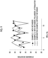
- Fig. 9 is a graph representing results of comparing the standard deviations for well numbers corresponding to imaging positions of the interference images between the apparatuses.
- Fig. 10 is a graph representing results of comparing an average value, a maximum value, and a minimum value of 36 locations of the standard deviations between the apparatuses.
- Example 1 corresponds to the holography apparatus 10 according to the first embodiment
- Example 2 corresponds to the holography apparatus 10A according to the second embodiment
- a comparative example corresponds to the holography apparatus according to the comparative example.
- the holography apparatus comprises the retarder as means for correcting the fluctuation in the polarization direction of the object light due to the birefringence of the substrate 61, and thus, the standard deviation of the pixel value of the interference image was increased and the variation in the standard deviation was decreased.
- the retarder due to the correction of the polarization direction by the retarder, the reduction in the contrast of the interference image due to the birefringence of the substrate 61 is suppressed, and the variation in the contrast is suppressed.
- the cell evaluation method according to the present embodiment uses the holography apparatus 10 according to the first embodiment or the holography apparatus 10A according to the second embodiment described above.
- the cell evaluation method includes acquiring the interference image generated by the object light L1 transmitted through the substrate 61 and the cell 60 and the reference light L2 by disposing the cell 60 cultured on the substrate 61 having transparency to the object light L1 on the optical path of the object light L1, generating a phase image from the interference image, and evaluating the cell by using the phase image.
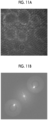
- Figs. 11A to 11D are acquired for aggregates (spheres) of induced pluripotent stem cells (iPS cells).
- an interference image (hologram) of a cell illustrated in Fig. 11A acquired by the imaging unit 40 is trimmed to have a size of, for example, 2048 ⁇ 2048, and is then subjected to two-dimensional Fourier transform.
- Fig. 11B is an example of a Fourier-transformed image of the cell obtained by this processing.
- Fig. 11B illustrates an image based on direct light, object light, and conjugated light.
- a position of the object light is specified by specifying a deviation amount of the object light with respect to the direct light in the Fourier-transformed image, and a complex amplitude component of only the object light is extracted by frequency filtering processing using a mask of a circular opening having a radius of 250 pixels.
- an angular spectrum method is applied to restore the image showing the phase of the cell at any spatial position.
- an angular spectrum U(f x , f y ; 0) of the Fourier-transformed image of a wave front u(x, y; 0) captured by the imaging surface of the imaging unit 40 is obtained.
- the angular spectrum U (f x , f y ; 0) is multiplied by a transfer function H(f x , f y ; z), and thus, a wave front at any position z in an optical axis direction (z direction) is reproduced.
- the transfer function H(f x , f y ; z) is a frequency response function (Fourier transform of an impulse response function (green function)).
- Equation (2) an inverse Fourier transform is performed on a wave front U(f x , f y ; z) at the position z in the optical axis direction (z direction), and thus, a solution u(x, y; z) at the position z is derived.
- phase image is generated by deriving a phase ⁇ for u(x, y; z) as represented in Equation (3) below.
- Fig. 11C is an example of a phase image before unwrapping obtained by each processing described above.
- ⁇ arctan Im u Re u
- a phase in a phase difference image before unwrapping illustrated in Fig. 11C is convolved to a value of 0 to 2 ⁇ . Therefore, for example, portions of 2 ⁇ or more are joined by applying a phase connection (unwrapping) method such as unweighted least squares or Flynn's algorithm, and thus, a final phase image as illustrated in Fig. 11D can be obtained.
- a phase connection (unwrapping) method such as unweighted least squares or Flynn's algorithm
- Fig. 12 is a diagram illustrating a concept of a phase image I P .
- a phase amount at each pixel k of the phase image I P is three-dimensionally displayed.
- the phase amount at each pixel k of the phase image I P is illustrated on a plane in gray scale.
- phase amount P in the phase image I P is represented by Equation (4) below.
- phase in the present specification is a phase of an electric field amplitude in a case where light is regarded as an electromagnetic wave, and is used in a more general sense.
- a phase amount P k at each pixel k of the phase image I P can be represented by Equation (5) below.
- n k is a refractive index of the cell at a portion corresponding to each pixel k of the phase image I P
- d k is a thickness of the cell at the portion corresponding to each pixel k of the phase image IP
- ⁇ is a wavelength of the object light in a hologram optical system.
- the phase image of the cell is an image showing an optical path length distribution of the object light transmitted through the cell. Since an optical path length in the cell corresponds to a product of the refractive index of the cell and the thickness of the cell, the phase image of the cell includes information on the refractive index and the thickness (shape) of the cell as represented in Equation (5).
- An example of the cell evaluation method using the phase image is a method using a total phase amount P A derived from the phase image.
- the total phase amount P A is represented by Equation (6) below.
- s is an area of each pixel k of the phase image
- v k is a volume of the cell at the portion corresponding to each pixel k of the phase image.
- the total phase amount P A corresponds to an amount obtained by integrating and accumulating the phase amounts P k for the pixels of the phase image of the cell for all the pixels k.
- the pixel value of the phase image corresponds to the phase amount P k .
- Fig. 13 is a graph representing results of acquiring correlation characteristics between a volume of an aggregate (sphere) of iPS cells and the total phase amount P A . As illustrated in Fig. 13 , it was confirmed that the total phase amount P A and the volume of the aggregate were in a proportional relationship. In Fig. 13 , a trend line L S indicating a standard of correlation between the volume of the aggregate and the total phase amount P A is illustrated together with plots. A regression line derived from the plots illustrated in Fig. 13 is applied as the trend line L S .
- Fig. 13 illustrates phase images of aggregates corresponding to plots a1 and a2 present on the trend line L S , and phase images of aggregates corresponding to plots a3, a4, and a5 present at positions deviated from the trend line L S .
- a phase image in which the luminance is uniform over all the aggregates is obtained.
- a plurality of cells constituting the aggregates are homogeneous, and densities of the cells in the aggregates are uniform.
- phase image generated from a high-contrast interference image is used. That is, it is preferable that a phase image generated from an interference image captured in a state where the rotational position of the rotation mechanism 31 (and the retarder 30) is controlled such that the standard deviation or the variance of the pixel values in the interference image is maximized is used.
Landscapes
- Physics & Mathematics (AREA)
- General Physics & Mathematics (AREA)
- Engineering & Computer Science (AREA)
- Theoretical Computer Science (AREA)
- Computing Systems (AREA)
- Chemical & Material Sciences (AREA)
- Analytical Chemistry (AREA)
- General Health & Medical Sciences (AREA)
- Health & Medical Sciences (AREA)
- Biochemistry (AREA)
- Life Sciences & Earth Sciences (AREA)
- Optics & Photonics (AREA)
- Immunology (AREA)
- Pathology (AREA)
- Holo Graphy (AREA)
- Investigating Or Analysing Materials By Optical Means (AREA)
- Medical Informatics (AREA)
- Nuclear Medicine, Radiotherapy & Molecular Imaging (AREA)
- Radiology & Medical Imaging (AREA)
- Quality & Reliability (AREA)
- Computer Vision & Pattern Recognition (AREA)
Abstract
Description
- The disclosed technology relates to a holography apparatus and a cell evaluation method using the holography apparatus.
- The following technologies are known as technologies related to a cell evaluation method using a digital holography technology. For example,
WO2019/176427A describes a determination method for generating a phase difference image of a cell from a hologram obtained by capturing the cells which are an aggregate of a plurality of cells and determining a state of a cell based on the phase difference image and a shape index value corresponding to a shape of the cell. - In addition, the following technologies are known as technologies for avoiding deterioration in coherence between object light and reference light. For example,
JP2003-15509A - In the evaluation of the cell using the digital holography technology, for example, the cell cultured on a substrate having light transmittance such as a schale is irradiated with the object light. An interference image (hologram) generated by interference between the object light transmitted through the cell or the substrate and the reference light coherent to the object light is captured by an imaging apparatus. A wave front of a light wave transmitted through the cell is restored by performing numerical calculation based on light propagation on image data of the interference image. In accordance with the digital holography technology, it is possible to acquire three-dimensional information of the cell.
- The present inventors have found that contrast of the interference image acquired by using the holography technology deteriorates with a position dependence on the substrate, that is, a variation in the contrast of the interference image is large. It should be noted that, low contrast in the interference image means that a difference in luminance between interference fringes is small. In a case where reduction in the contrast is due to an optical system, the interference image cannot be said to accurately represent information on the cell, and it is considered that the evaluation of the cell based on such an interference image is not appropriate. In particular, in the evaluation of the cell such as embryonic cells that require individual evaluation, an increase in measurement error becomes a major problem.
- As a result of diligent studies, the present inventors have found that the variation in the contrast of the interference image is caused by birefringence of the substrate on which the cell is cultured, such as a schale. As illustrated in
Fig. 1 , the interference image is formed by combining object light L1 transmitted through acell 60 and asubstrate 61 with reference light L2 coherent to the object light. In order to cause the object light L1 and the reference light L2 to interfere with each other, the object light L1 and the reference light L2 need to be pieces of linearly polarized light, respectively, and polarization directions (polarization axes) thereof need to be aligned with each other. However, in a case where the object light L1 is transmitted through thesubstrate 61, birefringence occurs, and the object light becomes elliptically polarized light. Accordingly, a polarization axis of the object light L1 rotates, and the polarization direction of the object light L1 and the polarization direction of the reference light L2 are not aligned with each other. As a result, coherence between the object light L1 and the reference light L2 deteriorates, and the contrast of the interference image deteriorates. Since the magnitude of the birefringence varies depending on a position on thesubstrate 61, the contrast of the interference image changes depending on an irradiation position of the object light L1 on thesubstrate 61. - The disclosed technology has been made in view of the above points, and an object of the disclosed technology is to suppress a variation in contrast of an interference image acquired by using a holography technology.
- A holography apparatus according to the disclosed technology includes an optical system that forms an interference image due to interference between object light and reference light, the optical system including a retarder that is disposed on an optical path of the object light or the reference light and a rotation mechanism that rotates the retarder with an optical axis of the object light or the reference light as a rotation axis, an imaging unit that captures the interference image, and a control unit that derives an evaluation value for the interference image captured by the imaging unit, and controls a rotational position of the rotation mechanism based on the evaluation value.
- The evaluation value may be a standard deviation or a variance of pixel values of the interference image, and the control unit may control the rotational position of the rotation mechanism such that the evaluation value is maximized. The retarder may be a half-wave plate.
- The optical system may further include a polarizer that is disposed on the optical path of the object light, and an attenuator that is disposed on the optical path of the reference light to attenuate a light amount of the reference light. The control unit may control an attenuation amount of the attenuator such that a difference between luminance of an image due to the object light captured by the imaging unit and luminance of an image due to the reference light is in a predetermined range.
- A cell evaluation method according to the disclosed technology is a cell evaluation method using the holography apparatus described above including disposing a cell cultured on a substrate having transparency to the object light on the optical path of the object light to acquire the interference image due to the interference between the object light transmitted through the substrate and the cell and the reference light, generating a phase image from the interference image, and evaluating the cell by using the phase image.
- It is preferable that the phase image is generated from the interference image due to the interference between the object light transmitted through the substrate and the cell and the reference light, and the interference image is captured in a state where the rotational position of the rotation mechanism is controlled such that a standard deviation or a variance of pixel values of the interference image is maximized.
- In accordance with the disclosed technology, it is possible to suppress the variation in the contrast of the interference image acquired by using the holography technology.
-
-
Fig. 1 is a diagram illustrating an example of a procedure of generating an interference image acquired by using a holography technology. -
Fig. 2 is a diagram illustrating an example of a configuration of a holography apparatus according to an embodiment of the disclosed technology. -
Fig. 3 is a flowchart illustrating an example of a flow of processing executed by a control unit according to the embodiment of the disclosed technology. -
Fig. 4 is a graph representing an example of a relationship between a rotational position of a retarder and a standard deviation of a pixel value of image data of the interference image according to the embodiment of the disclosed technology. -
Fig. 5 is a diagram illustrating an example of a configuration of the holography apparatus according to the embodiment of the disclosed technology. -
Fig. 6 is a diagram illustrating an example of the configuration of the holography apparatus according to the embodiment of the disclosed technology. -
Fig. 7 is a diagram illustrating an example of the configuration of the holography apparatus according to the embodiment of the disclosed technology. -
Fig. 8 is a flowchart illustrating an example of a flow of processing executed by the control unit according to the embodiment of the disclosed technology. -
Fig. 9 is a graph representing results of comparing standard deviations for each well number corresponding to an imaging position of the interference image between the apparatuses. -
Fig. 10 is a graph representing results of comparing an average value, a maximum value, and a minimum value of standard deviations of the pixel values acquired at 36 locations on a substrate between the apparatuses. -
Fig. 11A is a diagram illustrating an example of an interference image of an aggregate. -
Fig. 11B is a diagram illustrating an example of a Fourier-transformed image of the aggregate. -
Fig. 11C is a diagram illustrating an example of a phase difference image of an aggregate before unwrapping. -
Fig. 11D is a diagram illustrating an example of a phase difference image of an aggregate after unwrapping. -
Fig. 12 is a diagram illustrating a concept of the phase difference image according to the embodiment of the disclosed technology. -
Fig. 13 is a graph representing results of acquiring correlation characteristics between a volume of the aggregate and a total phase amount. - Hereinafter, examples of embodiments of the present invention will be described with reference to the drawings. It should be noted that, in each of the drawings, the same or equivalent components and portions are denoted by the same reference numerals, and the repeated description thereof will be omitted as appropriate.
-
Fig. 2 is a diagram illustrating an example of a configuration of aholography apparatus 10 according to a first embodiment of the disclosed technology. Theholography apparatus 10 includes alaser light source 20, anoptical system 200, animaging unit 40, and acontrol unit 50. Theoptical system 200 is configured to form an interference image due to interference between object light L1 and reference light L2, and includes asplitter 21,reflection mirrors objective lens 23, animaging lens 25, acombiner 26, aretarder 30, and arotation mechanism 31. Theholography apparatus 10 according to the present embodiment can be used for evaluating cells. Acell 60 to be evaluated is cultured on asubstrate 61 and is disposed between thereflection mirror 22 and theobjective lens 23 in a state where the cell is attached to thesubstrate 61 or floats from thesubstrate 61. A type of thecell 60 is not particularly limited, and may be, for example, an embryonic cell that may be required to perform individual evaluation for each cell. - For example, a HeNe laser having a wavelength of 632.8 nm can be used as the
laser light source 20. Laser light L0 which linearly polarized light emitted from thelaser light source 20 is divided into two laser light rays by thesplitter 21. One of two laser light rays is the object light L1 and the other is the reference light L2. A beam splitter can be used as thesplitter 21. The object light L1 is incident on thereflection mirror 22 via theretarder 30 held by therotation mechanism 31. Thecell 60 on thesubstrate 61 is irradiated with the object light L1 of which a traveling direction is bent by thereflection mirror 22. - The
substrate 61 may constitute a container generally used in cell culture, such as a schale or a well plate. Thesubstrate 61 is made of a material such as polystyrene having transparency to the object light L1. Thesubstrate 61 may be made of plastic or glass other than polystyrene. An image due to the object light L1 transmitted through thecell 60 and thesubstrate 61 is magnified by theobjective lens 23. The object light L1 transmitted through theobjective lens 23 is bent in the traveling direction by thereflection mirror 24 and is incident on thecombiner 26 through theimaging lens 25. On the other hand, the reference light L2 is also incident on thecombiner 26. The object light L1 and the reference light L2 are combined by thecombiner 26 and are captured on an imaging surface of theimaging unit 40. A beam splitter can be used as thecombiner 26. - The interference image (hologram) generated by the interference between the object light L1 and the reference light L2 is captured by the
imaging unit 40. Theimaging unit 40 comprises an imaging element such as a complementary metal-oxide-semiconductor (CMOS) image sensor, and generates image data of the interference image. The image data of the interference image is supplied to thecontrol unit 50. - The
retarder 30 is disposed between thesplitter 21 on an optical path of the object light L1 and thereflection mirror 22. Theretarder 30 has a function of changing a polarization direction of the object light L1. That is, theretarder 30 emits incidence ray while changing a polarization direction of the incidence ray in a direction corresponding to a rotational position of theretarder 30. Theretarder 30 may be, for example, a 1/2 wavelength plate (λ/2 plate). Therotation mechanism 31 rotates theretarder 30 with an optical axis of the object light L1 as a rotation axis based on a control signal supplied from thecontrol unit 50. Theretarder 30 is rotated, and thus, it is possible to determine a polarization direction of the object light L1 transmitted through theretarder 30 to be any direction. - The interference image generated by the object light L1 and the reference light L2 is formed by combining the object light L1 and the reference light L2 transmitted through the
cell 60 and thesubstrate 61. In order to cause the object light L1 and the reference light L2 to interfere with each other, the object light L1 and the reference light L2 need to be pieces of linearly polarized light, respectively, and polarization directions (polarization axes) thereof need to be aligned with each other. However, in a case where thesubstrate 61 is made of a material that causes birefringence, birefringence is caused in a case where the object light L1 passes through thesubstrate 61, and the object light L1 is elliptically polarized light. Accordingly, a polarization axis of the object light L1 rotates, and the polarization direction of the object light L1 and the polarization direction of the reference light L2 are not aligned with each other. As a result, coherence between the object light L1 and the reference light L2 deteriorates, and the contrast of the interference image deteriorates. However, the polarization direction of the object light L1 is changed by rotating theretarder 30, and thus, it is possible to cause the polarization direction of the object light L1 to coincide with the polarization direction of the reference light L2. Accordingly, it is possible to suppress the reduction in the contrast of the interference image. - The
control unit 50 derives an evaluation value for the interference image captured by theimaging unit 40, and controls the rotational position of the rotation mechanism 31 (and the retarder 30) based on the evaluation value. The evaluation value is an index value indicating the contrast of the interference image, and may be, for example, a standard deviation or a variance of pixel values in the image data of the interference image. The pixel value means a numerical value indicating the luminance of the pixel. The higher the coherence between the object light L1 and the reference light L2, the higher the contrast of the interference image, and the larger the standard deviation or the variance as the evaluation value. It can also be said that the evaluation value is an index value indicating the coherence between the object light L1 and the reference light L2. Thecontrol unit 50 controls the rotational position of the rotation mechanism 31 (and the retarder 30) such that the evaluation value is maximized. Specifically, thecontrol unit 50 includes a computer comprising a processor (not illustrated), and performs the following processing. -
Fig. 3 is a flowchart illustrating an example of a flow of processing executed by thecontrol unit 50. In step S1, thecontrol unit 50 sets the rotational position of the rotation mechanism 31 (and the retarder 30) to an initial position. In step S2, thecontrol unit 50 acquires the image data of the interference image from theimaging unit 40. In step S3, thecontrol unit 50 derives the evaluation value for the image data of the interference image acquired in step S2. Thecontrol unit 50 derives, for example, the standard deviation of the pixel value as the evaluation value and stores the derived value in a memory (not illustrated). - In step S4, the
control unit 50 determines whether or not the derivation of the evaluation values is completed for all predetermined rotational positions. Thecontrol unit 50 shifts the processing to step S5 in a case where it is determined that the derivation of the evaluation values is not completed for all the rotational positions, and shifts the processing to step S6 in a case where it is determined that the derivation of the evaluation values is completed. - In step S5, the
control unit 50 rotates the rotational position of the rotation mechanism 31 (and the retarder 30) by one step. Accordingly, theretarder 30 rotates the rotational position of the rotation mechanism by one step (for example, 5°) with the optical axis of the object light L1 as the rotation axis. Thereafter, thecontrol unit 50 returns the processing to step S2. That is, thecontrol unit 50 acquires the image data of the interference image in a state where the rotational position of theretarder 30 is rotated by one step, and derives the evaluation value for the image data. Thecontrol unit 50 repeats the processing from step S2 to step S5 until, for example, a change amount of theretarder 30 from the initial position in the polarization direction reaches 180°. In a case where theretarder 30 is a 1/2 wavelength plate (λ/2 plate), the polarization direction of the object light L1 changes by 180° by changing the retarder by 90° from the initial position. - In step S6, the
control unit 50 positions the rotation mechanism 31 (and the retarder 30) at a rotational position where the evaluation value stored in the memory is maximized by supplying the control signal to therotation mechanism 31. - As described above, the
holography apparatus 10 according to the embodiment of the disclosed technology includes theoptical system 200 that forms the interference image due to the interference between the object light L1 and the reference light L2. Theoptical system 200 includes theretarder 30 disposed on the optical path of the object light L1 and therotation mechanism 31 that rotates theretarder 30 with the optical axis of the object light L1 as the rotation axis. Theholography apparatus 10 comprises theimaging unit 40 that captures the interference image, and thecontrol unit 50 that derives the evaluation value for the interference image captured by theimaging unit 40 and controls the rotational position of the rotation mechanism 31 (and the retarder 30) based on the evaluation value. An index value indicating a state of the contrast of the interference image such as the standard deviation or the variance of the pixel values in the image data of the interference image is used as the evaluation value. Thecontrol unit 50 controls the rotational position of the rotation mechanism 31 (and the retarder 30) such that the evaluation value is maximized. - In accordance with the
holography apparatus 10 according to the embodiment of the disclosed technology, even in a situation in which the contrast of the interference image deteriorates due to the birefringence on thesubstrate 61, the rotational position of the rotation mechanism 31 (and the retarder 30) is controlled such that the evaluation value is maximized, and thus, it is possible to cause the polarization direction of the object light L1 to coincide with the polarization direction of the reference light L2. Accordingly, it is possible to suppress the reduction in the contrast of the interference image. That is, in accordance with theholography apparatus 10, it is possible to suppress the influence of the birefringence on thesubstrate 61. In a case where the interference image is acquired for the cell present at each position on thesubstrate 61, whenever the rotational position of the rotation mechanism 31 (and the retarder 30) is controlled, it is possible to suppress a variation in the contrast of the interference image. -
Fig. 4 is a graph representing an example of a relationship between the rotational position of theretarder 30 and the standard deviation of the pixel value of the image data of the interference image.Fig. 4 illustrates a relationship between a case where thesubstrate 61 is disposed on the optical path of the object light L1 (with the substrate) and a case where thesubstrate 61 is not disposed (without the substrate). As illustrated inFig. 4 , thesubstrate 61 that causes birefringence is disposed on the optical path of the object light L1, and thus, the standard deviation with which the rotational position of theretarder 30 is 0° is reduced as compared with a case where thesubstrate 61 is not disposed. However, it has been confirmed that the standard deviation is increased and a maximum value is taken at a specific rotational position (near 35°) by changing the rotational position of theretarder 30. In addition, the maximum value of the standard deviation in a case where thesubstrate 61 was disposed and the maximum value of the standard deviation in a case where thesubstrate 61 was not disposed are equal. As a result, due to the control of the rotational position of theretarder 30, the contrast of the interference image can be improved to such an extent that the influence of the birefringence of thesubstrate 61 can be offset. -
Figs. 5 and6 are diagrams illustrating examples of configurations ofholography apparatuses 10 according to modified examples, respectively. As illustrated inFig. 5 , it is also possible to dispose theretarder 30 and therotation mechanism 31 on a rear side in the traveling direction of the object light L1 with respect to thecell 60 and thesubstrate 61. In the example illustrated inFig. 5 , theretarder 30 and therotation mechanism 31 are disposed between thereflection mirror 24 and theimaging lens 25. In this case, it is also possible to suppress the variation in the contrast of the interference image. In addition, as illustrated inFig. 6 , theretarder 30 and therotation mechanism 31 may be disposed on an optical path of the reference light L2. In this case, it is also possible to suppress the variation in the contrast of the interference image. -
Fig. 7 is a diagram illustrating an example of a configuration of aholography apparatus 10A according to a second embodiment of the disclosed technology. Theholography apparatus 10A according to the present embodiment is different from the holography apparatus 10 (seeFig. 2 ) according to the first embodiment in that apolarizer 27, anattenuator 28, afirst shutter 29A, and asecond shutter 29B (seeFig. 2 ) are further included. Thepolarizer 27 is disposed on the optical path of the object light L1. In the example illustrated inFig. 7 , thepolarizer 27 is disposed between thereflection mirror 24 and theimaging lens 25. Thepolarizer 27 is a polarizing filter having a function of removing a polarization component unnecessary for forming the interference image, which is included in the elliptically polarized light generated by the object light L1 transmitting through thesubstrate 61. - The
attenuator 28 is disposed on the optical path of the reference light L2. Theattenuator 28 has a function of attenuating the reference light L2 with an attenuation amount corresponding to the control signal supplied from thecontrol unit 50. The object light L1 passes through thepolarizer 27, and thus, a light amount of the object light L1 is reduced. In a case where a light amount of the reference light L2 is not attenuated, the light amounts of the object light L1 and the reference light L2 are non-uniform. Therefore, thecontrol unit 50 controls an attenuation amount of theattenuator 28 such that an average pixel value (average luminance value) of the image data of the image due to only the object light L1 captured by theimaging unit 40 and an average pixel value (average luminance value) of the image data due to only the reference light L2 are the same. - The
first shutter 29A is disposed on the optical path of the object light L1. In the example illustrated inFig. 7 , thefirst shutter 29A is disposed between theimaging lens 25 and thecombiner 26, but may be disposed at any place as long as the first shutter is on the optical path of the object light L1. Thefirst shutter 29A switches between passing and blocking the object light L1 in response to the control signal supplied from thecontrol unit 50. - The
second shutter 29B is disposed on the optical path of the reference light L2. In the example illustrated inFig. 7 , thesecond shutter 29B is disposed between theattenuator 28 and thecombiner 26, but may be disposed at any place as long as the second shutter is on the optical path of the reference light L2. Thesecond shutter 29B switches between passing and blocking the reference light L2 in response to the control signal supplied from thecontrol unit 50. -
Fig. 8 is a flowchart illustrating an example of a flow of processing executed by thecontrol unit 50 according to the present embodiment. Each processing illustrated inFig. 8 is executed after the processing illustrated inFig. 3 is completed. - In step S11, the
control unit 50 controls thefirst shutter 29A to be in an opened state and controls thesecond shutter 29B to be in a closed state. Accordingly, the image due to only the object light L1 is captured by theimaging unit 40. In step S12, thecontrol unit 50 acquires the image data of the image due to only the object light L1 from theimaging unit 40. In step S13, thecontrol unit 50 derives an average pixel value (average luminance value) of an object light image indicated by the image data acquired in step S12, and stores the derived value in a memory (not illustrated). - In step S14, the
control unit 50 controls thefirst shutter 29A to be in the closed state and controls thesecond shutter 29B to be in the opened state. Accordingly, the image due to only the reference light L2 is captured by theimaging unit 40. In step S15, thecontrol unit 50 acquires the image data of the image due to only the reference light L2 from theimaging unit 40. In step S16, thecontrol unit 50 derives an average pixel value (average luminance value) of a reference light image indicated by the image data acquired in step S15, and stores the derived value in a memory (not illustrated). - In step S17, the
control unit 50 determines whether or not the average pixel value (average luminance value) of the object light image stored in the memory and the average pixel value (average luminance value) of the reference light image coincide with each other. Thecontrol unit 50 shifts the processing to step S18 in a case where it is determined that the average pixel values (average luminance values) do not coincide with each other, and shifts the processing to step S19 in a case where it is determined that the average pixel values (average luminance values) coincide with each other. - In step S18, the
control unit 50 increases the attenuation amount of theattenuator 28 by one step, and returns the processing to step S15. That is, thecontrol unit 50 performs the acquisition of the image data, the storing of the image data in the memory, and the derivation of the average pixel value (average luminance value) of the reference light image in a state where the attenuation amount of theattenuator 28 is increased by one step. Thecontrol unit 50 performs the processing from step S15 to step S18 until the average pixel value (average luminance value) of the object light image stored in the memory and the average pixel value (average luminance value) of the reference light image coincide with each other. In step S19, thecontrol unit 50 controls thefirst shutter 29A to be in the opened state and controls thesecond shutter 29B to be in the opened state. - In accordance with the
holography apparatus 10A according to the present embodiment, the polarization component unnecessary for forming the interference image, which is included in the elliptically polarized light generated by the object light L1 transmitting through thesubstrate 61, is removed by thepolarizer 27. In addition, the attenuation amount of theattenuator 28 is controlled such that the light amount of the object light L1 and the light amount of the reference light L2 are the same. Accordingly, an effect of suppressing the reduction in the contrast of the interference image and an effect of suppressing the variation in the contrast of the interference image are promoted. - It should be noted that, in the present embodiment, a case where the attenuation amount of the
attenuator 28 is controlled such that the luminance of the image due to the object light L1 and the luminance of the image due to the reference light L2 which are captured by theimaging unit 40 coincide with each other has been illustrated. However, the attenuation amount of theattenuator 28 may be controlled such that a difference between the luminance of the image due to the object light L1 and the luminance of the image due to the reference light L2 is within a predetermined range. - Interference images were formed by using the
holography apparatus 10 according to the first embodiment (seeFig. 2 ), theholography apparatus 10A according to the second embodiment (seeFig. 7 ), and a holography apparatus according to a comparative example (not illustrated), and contrasts and variations of the interference images were compared. - The components of the holography apparatuses are represented in Table 1 below. The
holography apparatus 10 according to the first embodiment has a configuration that does not comprise the polarizer and the attenuator among the components represented in Table 1. The holography apparatus according to the comparative example has a configuration that does not comprise the retarder, the rotation mechanism, the polarizer, and the attenuator among the components represented in Table 1. That is, the holography apparatus according to the comparative example does not have means for correcting a fluctuation in the polarization direction of the object light due to the birefringence of thesubstrate 61.[Table 1] Component Manufacturer Model number Laser light source Thorlabs HNL100LB Splitter Thorlabs TW630R5F1 Retarder Thorlabs WPHSM05-633 Rotation mechanism Thorlabs ELL 14 Substrate Cooper Surgical 38Special GPS Objective lens Nikon CFI Plan Apochromat Lambda 10x Imaging lens Edmund Optics TS Achromatic lens 50 × 100 VIS-NIR INKCombiner Thorlabs BP250 Imaging unit Baumer VCXU-50 Control unit DELL Precision 7820T Polarizer SIGMAKOKI SPF-50C-32 Attenuator Thorlabs V600F - Embryonic cells were cultured in 12 wells of the substrate. In the holography apparatuses, pieces of image data of interference images of embryonic cells were acquired for a total of three substrates at 12 locations per substrate. That is, the number of acquired interference images in the holography apparatuses is 36. A standard deviation of a pixel value was derived for each of the acquired image data of the interference image.
-
Fig. 9 is a graph representing results of comparing the standard deviations for well numbers corresponding to imaging positions of the interference images between the apparatuses.Fig. 10 is a graph representing results of comparing an average value, a maximum value, and a minimum value of 36 locations of the standard deviations between the apparatuses. InFigs. 9 and10 , Example 1 corresponds to theholography apparatus 10 according to the first embodiment, Example 2 corresponds to theholography apparatus 10A according to the second embodiment, and a comparative example corresponds to the holography apparatus according to the comparative example. - As illustrated in
Figs. 9 and10 , it was confirmed that the holography apparatus comprises the retarder as means for correcting the fluctuation in the polarization direction of the object light due to the birefringence of thesubstrate 61, and thus, the standard deviation of the pixel value of the interference image was increased and the variation in the standard deviation was decreased. As a result, due to the correction of the polarization direction by the retarder, the reduction in the contrast of the interference image due to the birefringence of thesubstrate 61 is suppressed, and the variation in the contrast is suppressed. - Hereinafter, a cell evaluation method according to an embodiment of the disclosed technology will be described. The cell evaluation method according to the present embodiment uses the
holography apparatus 10 according to the first embodiment or theholography apparatus 10A according to the second embodiment described above. - The cell evaluation method according to the present embodiment includes acquiring the interference image generated by the object light L1 transmitted through the
substrate 61 and thecell 60 and the reference light L2 by disposing thecell 60 cultured on thesubstrate 61 having transparency to the object light L1 on the optical path of the object light L1, generating a phase image from the interference image, and evaluating the cell by using the phase image. - Hereinafter, an example of a method for acquiring the phase image from the interference image will be described with reference to
Figs. 11A to 11D . It should be noted that,Figs. 11A to 11D are acquired for aggregates (spheres) of induced pluripotent stem cells (iPS cells). - First, an interference image (hologram) of a cell illustrated in
Fig. 11A acquired by theimaging unit 40 is trimmed to have a size of, for example, 2048 × 2048, and is then subjected to two-dimensional Fourier transform.Fig. 11B is an example of a Fourier-transformed image of the cell obtained by this processing.Fig. 11B illustrates an image based on direct light, object light, and conjugated light. - Subsequently, a position of the object light is specified by specifying a deviation amount of the object light with respect to the direct light in the Fourier-transformed image, and a complex amplitude component of only the object light is extracted by frequency filtering processing using a mask of a circular opening having a radius of 250 pixels.
- Subsequently, for example, an angular spectrum method is applied to restore the image showing the phase of the cell at any spatial position. Specifically, an angular spectrum U(fx, fy; 0) of the Fourier-transformed image of a wave front u(x, y; 0) captured by the imaging surface of the
imaging unit 40 is obtained. Subsequently, as represented in Equation (1) below, the angular spectrum U (fx, fy; 0) is multiplied by a transfer function H(fx, fy; z), and thus, a wave front at any position z in an optical axis direction (z direction) is reproduced. Here, the transfer function H(fx, fy; z) is a frequency response function (Fourier transform of an impulse response function (green function)).
- Subsequently, as represented in Equation (2) below, an inverse Fourier transform is performed on a wave front U(fx, fy; z) at the position z in the optical axis direction (z direction), and thus, a solution u(x, y; z) at the position z is derived.

- Subsequently, the phase image is generated by deriving a phase ϕ for u(x, y; z) as represented in Equation (3) below.
Fig. 11C is an example of a phase image before unwrapping obtained by each processing described above.
- A phase in a phase difference image before unwrapping illustrated in
Fig. 11C is convolved to a value of 0 to 2π. Therefore, for example, portions of 2π or more are joined by applying a phase connection (unwrapping) method such as unweighted least squares or Flynn's algorithm, and thus, a final phase image as illustrated inFig. 11D can be obtained. It should be noted that, many unwrapping methods have been proposed, and an appropriate method that does not cause phase mismatch may be appropriately selected. - Hereinafter, the phase image will be described.
Fig. 12 is a diagram illustrating a concept of a phase image IP. In a lower part ofFig. 12 , a phase amount at each pixel k of the phase image IP is three-dimensionally displayed. In an upper part ofFig. 12 , the phase amount at each pixel k of the phase image IP is illustrated on a plane in gray scale. - Here, in a case where a phase of a background (region where the cell is not present) present in the same focal plane of the phase image IP is PB and a phase of a region where the cell is present is PS, a phase amount P in the phase image IP is represented by Equation (4) below. In addition, the term "phase" in the present specification is a phase of an electric field amplitude in a case where light is regarded as an electromagnetic wave, and is used in a more general sense.

- In addition, a phase amount Pk at each pixel k of the phase image IP can be represented by Equation (5) below. Here, nk is a refractive index of the cell at a portion corresponding to each pixel k of the phase image IP, dk is a thickness of the cell at the portion corresponding to each pixel k of the phase image IP, and λ is a wavelength of the object light in a hologram optical system.

- The phase image of the cell is an image showing an optical path length distribution of the object light transmitted through the cell. Since an optical path length in the cell corresponds to a product of the refractive index of the cell and the thickness of the cell, the phase image of the cell includes information on the refractive index and the thickness (shape) of the cell as represented in Equation (5).
- An example of the cell evaluation method using the phase image is a method using a total phase amount PA derived from the phase image. The total phase amount PA is represented by Equation (6) below. Here, s is an area of each pixel k of the phase image, and vk is a volume of the cell at the portion corresponding to each pixel k of the phase image. As represented in Equation (6), the total phase amount PA corresponds to an amount obtained by integrating and accumulating the phase amounts Pk for the pixels of the phase image of the cell for all the pixels k. The pixel value of the phase image corresponds to the phase amount Pk.

-
Fig. 13 is a graph representing results of acquiring correlation characteristics between a volume of an aggregate (sphere) of iPS cells and the total phase amount PA. As illustrated inFig. 13 , it was confirmed that the total phase amount PA and the volume of the aggregate were in a proportional relationship. InFig. 13 , a trend line LS indicating a standard of correlation between the volume of the aggregate and the total phase amount PA is illustrated together with plots. A regression line derived from the plots illustrated inFig. 13 is applied as the trend line LS. -
Fig. 13 illustrates phase images of aggregates corresponding to plots a1 and a2 present on the trend line LS, and phase images of aggregates corresponding to plots a3, a4, and a5 present at positions deviated from the trend line LS. For the aggregates corresponding to the plots a1 and a2 present on the trend line LS, a phase image in which the luminance is uniform over all the aggregates is obtained. As a result, a plurality of cells constituting the aggregates are homogeneous, and densities of the cells in the aggregates are uniform. On the other hand, for the aggregates corresponding to the plots a3 and a4 present at the positions deviated from the trend line LS, a phase image in which luminance of a central portion is lower than luminance of other portions is obtained. As a result, the plurality of cells constituting the aggregates are an inhomogeneous, and the densities of the cells in the aggregates are non-uniform. In addition, for the aggregate corresponding to the plot a5 present at the position deviated from the trend line LS, a phase difference image in which unevenness of a contour line of the aggregate is remarkable is obtained. As a result, an abnormality occurs in the cells constituting the aggregates. - From the above results, it can be said that it is possible to determine the state of the aggregate by using the correlation between the total phase amount PA and the volume of the aggregate. In addition, it can be said that it is possible to determine the state of the aggregate in accordance with a degree of deviation from the trend line LS in a correlation for the aggregate to be determined by comparing the trend line LS indicating the correlation between the total phase amount PA and the volume of the aggregate with the correlation between the total phase amount PA of the aggregate to be determined and the volume of the aggregate. Specifically, it can be said that it is possible to determine the state of each aggregate in accordance with the degree of deviation from the trend line LS of the plot of the aggregate to be determined which is plotted on the graph in which the volume of the aggregate is taken on one axis and the total phase amount PA is taken on the other axis. Consequently, for example, for the aggregate in which a minus width of the total phase amount PA from the trend line LS is equal to or more than a threshold value, it is possible to determine that there is an abnormality in at least one of the density, homogeneity of the plurality of cells included in the aggregate, or an outer shape of the sphere.
- In the cell evaluation using the phase image, it is preferable that a phase image generated from a high-contrast interference image is used. That is, it is preferable that a phase image generated from an interference image captured in a state where the rotational position of the rotation mechanism 31 (and the retarder 30) is controlled such that the standard deviation or the variance of the pixel values in the interference image is maximized is used.
- It should be noted that, the disclosure of
Japanese Patent Application No. 2021-066769 filed on April 9, 2021
Claims (7)
- A holography apparatus comprising:an optical system that forms an interference image due to interference between object light and reference light, the optical system including a retarder that is disposed on an optical path of the object light or the reference light and a rotation mechanism that rotates the retarder with an optical axis of the object light or the reference light as a rotation axis;an imaging unit that captures the interference image; anda control unit that derives an evaluation value for the interference image captured by the imaging unit, and controls a rotational position of the rotation mechanism based on the evaluation value.
- The holography apparatus according to claim 1,wherein the evaluation value is a standard deviation or a variance of pixel values of the interference image, andthe control unit controls the rotational position of the rotation mechanism such that the evaluation value is maximized.
- The holography apparatus according to claim 1,
wherein the retarder is a half-wave plate. - The holography apparatus according to any one of claims 1 to 3,
wherein the optical system further includesa polarizer that is disposed on the optical path of the object light, andan attenuator that is disposed on the optical path of the reference light to attenuate a light amount of the reference light. - The holography apparatus according to claim 4,
wherein the control unit controls an attenuation amount of the attenuator such that a difference between luminance of an image due to the object light captured by the imaging unit and luminance of an image due to the reference light is in a predetermined range. - A cell evaluation method using the holography apparatus according to any one of claims 1 to 5, the method comprising:disposing a cell cultured on a substrate having transparency to the object light on the optical path of the object light to acquire the interference image due to the interference between the object light transmitted through the substrate and the cell and the reference light;generating a phase image from the interference image; andevaluating the cell by using the phase image.
- The cell evaluation method according to claim 6,
wherein the phase image is generated from the interference image due to the interference between the object light transmitted through the substrate and the cell and the reference light, and the interference image is captured in a state where the rotational position of the rotation mechanism is controlled such that a standard deviation or a variance of pixel values of the interference image is maximized.
Applications Claiming Priority (2)
| Application Number | Priority Date | Filing Date | Title |
|---|---|---|---|
| JP2021066769 | 2021-04-09 | ||
| PCT/JP2022/012806 WO2022215499A1 (en) | 2021-04-09 | 2022-03-18 | Holography device and cell evaluation method |
Publications (2)
| Publication Number | Publication Date |
|---|---|
| EP4321936A1 true EP4321936A1 (en) | 2024-02-14 |
| EP4321936A4 EP4321936A4 (en) | 2024-09-18 |
Family
ID=83545426
Family Applications (1)
| Application Number | Title | Priority Date | Filing Date |
|---|---|---|---|
| EP22784484.2A Pending EP4321936A4 (en) | 2021-04-09 | 2022-03-18 | HOLOGRAPHY DEVICE AND CELL EVALUATION METHOD |
Country Status (5)
| Country | Link |
|---|---|
| US (1) | US12591203B2 (en) |
| EP (1) | EP4321936A4 (en) |
| JP (1) | JP7779905B2 (en) |
| CN (1) | CN117098987A (en) |
| WO (1) | WO2022215499A1 (en) |
Family Cites Families (17)
| Publication number | Priority date | Publication date | Assignee | Title |
|---|---|---|---|---|
| JPS58176511A (en) * | 1982-04-09 | 1983-10-17 | Hitachi Ltd | Method and device for interference |
| JPH04269603A (en) * | 1991-02-26 | 1992-09-25 | Olympus Optical Co Ltd | Interference measuring apparatus |
| JP2003015509A (en) | 2001-06-27 | 2003-01-17 | Sony Corp | Image exposure recording apparatus and image exposure recording method |
| US7633631B2 (en) | 2007-04-04 | 2009-12-15 | Nikon Corporation | Three-dimensional microscope and method for obtaining three-dimensional image |
| CN101509813A (en) * | 2009-03-31 | 2009-08-19 | 昆明理工大学 | Rotating reference light polarization direction digital holographic photoelastic sensitivity two dimensional stress field detecting method |
| CN103025859A (en) | 2010-05-25 | 2013-04-03 | 阿尔利克斯公司 | Methods and apparatuses for detection of positional freedom of particles in biological and chemical analyses and applications in immunodiagnostics |
| JP2014010019A (en) | 2012-06-28 | 2014-01-20 | Nikon Corp | Interference measurement |
| EP2930461A4 (en) * | 2012-12-06 | 2015-12-02 | 3Dragons Llc | Three-dimensional shape measuring device, method for acquiring hologram image, and method for measuring three-dimensional shape |
| FR3030748B1 (en) | 2014-12-17 | 2017-01-27 | Commissariat Energie Atomique | OBJECT OBSERVATION SYSTEM |
| WO2018147473A1 (en) * | 2017-02-10 | 2018-08-16 | 国立大学法人京都工芸繊維大学 | Three-dimensional object information measuring device |
| KR101990009B1 (en) * | 2017-08-25 | 2019-09-30 | 주식회사 내일해 | An Improved Holographic Reconstruction Apparatus and Method |
| EP3766984B1 (en) | 2018-03-12 | 2024-10-30 | FUJIFILM Corporation | Determination method` |
| CN109946941A (en) * | 2019-04-17 | 2019-06-28 | 上海师范大学 | Optical image encryption system and method based on interference of Sagnac effect |
| JP7026853B2 (en) | 2019-06-28 | 2022-02-28 | 富士フイルム株式会社 | Image processing equipment, evaluation system, image processing program and image processing method |
| CN110455799B (en) * | 2019-07-23 | 2022-06-17 | 长春理工大学 | A high-resolution holographic microscope and method for live cell imaging |
| JP2021066769A (en) | 2019-10-18 | 2021-04-30 | 日鉄テックスエンジ株式会社 | Kiln core detection device |
| CN112506019B (en) * | 2020-11-29 | 2022-05-03 | 北京工业大学 | Off-axis digital holographic imaging reconstruction method based on kronecker product interpolation |
-
2022
- 2022-03-18 EP EP22784484.2A patent/EP4321936A4/en active Pending
- 2022-03-18 JP JP2023512907A patent/JP7779905B2/en active Active
- 2022-03-18 CN CN202280026344.2A patent/CN117098987A/en active Pending
- 2022-03-18 WO PCT/JP2022/012806 patent/WO2022215499A1/en not_active Ceased
-
2023
- 2023-09-28 US US18/476,317 patent/US12591203B2/en active Active
Also Published As
| Publication number | Publication date |
|---|---|
| JPWO2022215499A1 (en) | 2022-10-13 |
| EP4321936A4 (en) | 2024-09-18 |
| US20240027959A1 (en) | 2024-01-25 |
| WO2022215499A1 (en) | 2022-10-13 |
| US12591203B2 (en) | 2026-03-31 |
| JP7779905B2 (en) | 2025-12-03 |
| CN117098987A (en) | 2023-11-21 |
Similar Documents
| Publication | Publication Date | Title |
|---|---|---|
| DE69924129T2 (en) | METHOD AND DEVICE FOR THE SIMULTANEOUS PICTURE OF AMPLITUDE AND QUANTITATIVE PHASE CONTRASTING BY NUMERICAL RECONSTRUCTION OF DIGITAL HOLOGRAMS | |
| KR101159495B1 (en) | Methods and apparatus for wavefront manipulations and improved 3-d measurements | |
| Da Silva et al. | A Fizeau interferometry stitching system to characterize X-ray mirrors with sub-nanometre errors | |
| CN107014784B (en) | Device and method for measuring vector transmission matrix of scattering medium | |
| EP3137946B1 (en) | Apparatus and method for using birefringent lenses to create holograms from received electromagnetic radiation | |
| EP2084488A2 (en) | Optical devices based on internal conical diffraction | |
| Khmaladze et al. | Simultaneous dual-wavelength reflection digital holography applied to the study of the porous coal samples | |
| JP2006023307A (en) | Method for the emulation of microscope imaging systems and high aperture imaging systems, in particular for mask inspection | |
| CN105066908A (en) | Digital holography three-directional shape detection device based on multi-wavelengths and multi-polarization states | |
| US20250155603A1 (en) | Metasurface enabled quantitative phase imaging | |
| JPH07301834A (en) | Optical self-correlation device | |
| Sokkar et al. | Adaptive spatial carrier frequency method for fast monitoring optical properties of fibres | |
| KR20230123956A (en) | Optical measuring system and optical measuring method | |
| JP2018205430A (en) | Phase shift digital holography apparatus and program thereof | |
| EP4321936A1 (en) | Holography device and cell evaluation method | |
| CN100445781C (en) | Method and device for generating radially and/or horizontally polarized light beams | |
| CN111912603A (en) | Method and system for calibrating phase-type spatial light modulator based on optical differentiator | |
| Wdowiak et al. | Quantitative phase imaging verification in large field-of-view lensless holographic microscopy via two-photon 3D printing | |
| US20240029253A1 (en) | Method for acquiring evaluation value | |
| Matkivsky et al. | Correction of aberrations in digital holography using the phase gradient autofocus technique | |
| JP3871183B2 (en) | Method and apparatus for measuring three-dimensional shape of optical element | |
| Chen et al. | Imaging evaluation of computer-generated hologram by using three-dimensional modified structural similarity index | |
| CN119960279B (en) | A compact dual-wavelength common-path holographic microscope | |
| Colomb | Numerical aberrations compensation and polarization imaging in digital holographic microscopy | |
| Mirando et al. | Speckle reduction in retrieved phase using digital holography with transport of intensity |
Legal Events
| Date | Code | Title | Description |
|---|---|---|---|
| STAA | Information on the status of an ep patent application or granted ep patent |
Free format text: STATUS: THE INTERNATIONAL PUBLICATION HAS BEEN MADE |
|
| PUAI | Public reference made under article 153(3) epc to a published international application that has entered the european phase |
Free format text: ORIGINAL CODE: 0009012 |
|
| STAA | Information on the status of an ep patent application or granted ep patent |
Free format text: STATUS: REQUEST FOR EXAMINATION WAS MADE |
|
| 17P | Request for examination filed |
Effective date: 20231005 |
|
| AK | Designated contracting states |
Kind code of ref document: A1 Designated state(s): AL AT BE BG CH CY CZ DE DK EE ES FI FR GB GR HR HU IE IS IT LI LT LU LV MC MK MT NL NO PL PT RO RS SE SI SK SM TR |
|
| DAV | Request for validation of the european patent (deleted) | ||
| DAX | Request for extension of the european patent (deleted) | ||
| A4 | Supplementary search report drawn up and despatched |
Effective date: 20240816 |
|
| RIC1 | Information provided on ipc code assigned before grant |
Ipc: G02B 21/14 20060101ALN20240809BHEP Ipc: G03H 1/00 20060101ALI20240809BHEP Ipc: G01N 21/45 20060101ALI20240809BHEP Ipc: G03H 1/08 20060101ALI20240809BHEP Ipc: G03H 1/04 20060101ALI20240809BHEP Ipc: G03H 1/02 20060101AFI20240809BHEP |