EP4321928A1 - Temperature adjustment apparatus and control apparatus - Google Patents
Temperature adjustment apparatus and control apparatus Download PDFInfo
- Publication number
- EP4321928A1 EP4321928A1 EP23190205.7A EP23190205A EP4321928A1 EP 4321928 A1 EP4321928 A1 EP 4321928A1 EP 23190205 A EP23190205 A EP 23190205A EP 4321928 A1 EP4321928 A1 EP 4321928A1
- Authority
- EP
- European Patent Office
- Prior art keywords
- liquid crystal
- crystal panel
- conversion device
- thermoelectric conversion
- processing
- Prior art date
- Legal status (The legal status is an assumption and is not a legal conclusion. Google has not performed a legal analysis and makes no representation as to the accuracy of the status listed.)
- Pending
Links
Images






Classifications
-
- G—PHYSICS
- G05—CONTROLLING; REGULATING
- G05D—SYSTEMS FOR CONTROLLING OR REGULATING NON-ELECTRIC VARIABLES
- G05D23/00—Control of temperature
- G05D23/19—Control of temperature characterised by the use of electric means
- G05D23/20—Control of temperature characterised by the use of electric means with sensing elements having variation of electric or magnetic properties with change of temperature
-
- G—PHYSICS
- G02—OPTICS
- G02F—OPTICAL DEVICES OR ARRANGEMENTS FOR THE CONTROL OF LIGHT BY MODIFICATION OF THE OPTICAL PROPERTIES OF THE MEDIA OF THE ELEMENTS INVOLVED THEREIN; NON-LINEAR OPTICS; FREQUENCY-CHANGING OF LIGHT; OPTICAL LOGIC ELEMENTS; OPTICAL ANALOGUE/DIGITAL CONVERTERS
- G02F1/00—Devices or arrangements for the control of the intensity, colour, phase, polarisation or direction of light arriving from an independent light source, e.g. switching, gating or modulating; Non-linear optics
- G02F1/01—Devices or arrangements for the control of the intensity, colour, phase, polarisation or direction of light arriving from an independent light source, e.g. switching, gating or modulating; Non-linear optics for the control of the intensity, phase, polarisation or colour
- G02F1/13—Devices or arrangements for the control of the intensity, colour, phase, polarisation or direction of light arriving from an independent light source, e.g. switching, gating or modulating; Non-linear optics for the control of the intensity, phase, polarisation or colour based on liquid crystals, e.g. single liquid crystal display cells
- G02F1/133—Constructional arrangements; Operation of liquid crystal cells; Circuit arrangements
- G02F1/1333—Constructional arrangements; Manufacturing methods
- G02F1/133382—Heating or cooling of liquid crystal cells other than for activation, e.g. circuits or arrangements for temperature control, stabilisation or uniform distribution over the cell
- G02F1/133385—Heating or cooling of liquid crystal cells other than for activation, e.g. circuits or arrangements for temperature control, stabilisation or uniform distribution over the cell with cooling means, e.g. fans
-
- G—PHYSICS
- G03—PHOTOGRAPHY; CINEMATOGRAPHY; ANALOGOUS TECHNIQUES USING WAVES OTHER THAN OPTICAL WAVES; ELECTROGRAPHY; HOLOGRAPHY
- G03B—APPARATUS OR ARRANGEMENTS FOR TAKING PHOTOGRAPHS OR FOR PROJECTING OR VIEWING THEM; APPARATUS OR ARRANGEMENTS EMPLOYING ANALOGOUS TECHNIQUES USING WAVES OTHER THAN OPTICAL WAVES; ACCESSORIES THEREFOR
- G03B21/00—Projectors or projection-type viewers; Accessories therefor
- G03B21/14—Details
- G03B21/16—Cooling; Preventing overheating
-
- G—PHYSICS
- G03—PHOTOGRAPHY; CINEMATOGRAPHY; ANALOGOUS TECHNIQUES USING WAVES OTHER THAN OPTICAL WAVES; ELECTROGRAPHY; HOLOGRAPHY
- G03B—APPARATUS OR ARRANGEMENTS FOR TAKING PHOTOGRAPHS OR FOR PROJECTING OR VIEWING THEM; APPARATUS OR ARRANGEMENTS EMPLOYING ANALOGOUS TECHNIQUES USING WAVES OTHER THAN OPTICAL WAVES; ACCESSORIES THEREFOR
- G03B21/00—Projectors or projection-type viewers; Accessories therefor
- G03B21/005—Projectors using an electronic spatial light modulator but not peculiar thereto
-
- H—ELECTRICITY
- H10—SEMICONDUCTOR DEVICES; ELECTRIC SOLID-STATE DEVICES NOT OTHERWISE PROVIDED FOR
- H10N—ELECTRIC SOLID-STATE DEVICES NOT OTHERWISE PROVIDED FOR
- H10N10/00—Thermoelectric devices comprising a junction of dissimilar materials, i.e. devices exhibiting Seebeck or Peltier effects
- H10N10/10—Thermoelectric devices comprising a junction of dissimilar materials, i.e. devices exhibiting Seebeck or Peltier effects operating with only the Peltier or Seebeck effects
- H10N10/13—Thermoelectric devices comprising a junction of dissimilar materials, i.e. devices exhibiting Seebeck or Peltier effects operating with only the Peltier or Seebeck effects characterised by the heat-exchanging means at the junction
-
- G—PHYSICS
- G02—OPTICS
- G02F—OPTICAL DEVICES OR ARRANGEMENTS FOR THE CONTROL OF LIGHT BY MODIFICATION OF THE OPTICAL PROPERTIES OF THE MEDIA OF THE ELEMENTS INVOLVED THEREIN; NON-LINEAR OPTICS; FREQUENCY-CHANGING OF LIGHT; OPTICAL LOGIC ELEMENTS; OPTICAL ANALOGUE/DIGITAL CONVERTERS
- G02F1/00—Devices or arrangements for the control of the intensity, colour, phase, polarisation or direction of light arriving from an independent light source, e.g. switching, gating or modulating; Non-linear optics
- G02F1/01—Devices or arrangements for the control of the intensity, colour, phase, polarisation or direction of light arriving from an independent light source, e.g. switching, gating or modulating; Non-linear optics for the control of the intensity, phase, polarisation or colour
- G02F1/13—Devices or arrangements for the control of the intensity, colour, phase, polarisation or direction of light arriving from an independent light source, e.g. switching, gating or modulating; Non-linear optics for the control of the intensity, phase, polarisation or colour based on liquid crystals, e.g. single liquid crystal display cells
- G02F1/133—Constructional arrangements; Operation of liquid crystal cells; Circuit arrangements
- G02F1/1333—Constructional arrangements; Manufacturing methods
- G02F1/133382—Heating or cooling of liquid crystal cells other than for activation, e.g. circuits or arrangements for temperature control, stabilisation or uniform distribution over the cell
Definitions
- the present disclosure relates to a temperature adjustment apparatus and a control appa ratus.
- a projector forming an image according to image information and projecting the formed image is known (for example, see JP-A-2015-108697 ).
- the projector disclosed in JP-A-2015-108697 includes a liquid crystal panel modulating incident light and a cooling apparatus cooling the liquid crystal panel.
- the cooling apparatus includes an optical device holding unit, a liquid pressure feeding unit, a supply tank, a heat exchange unit, a plurality of tubular members, and a cooling fan.
- the optical device holding unit has a channel in which a cooling liquid circulates and holds the liquid crystal panel.
- the heat exchange unit is coupled to the optical device holding unit via the plurality of tubular members. In the heat exchange unit, the cooling liquid circulates from the optical device holding unit.
- the heat exchange unit includes a heat receiving portion, a Peltier element as a thermoelectric conversion element, a heat sink, or the like.
- the heat receiving portion receives heat of the liquid crystal panel via the optical device holding unit and the cooling liquid, and the Peltier element conducts the heat received by the heat receiving portion to the heat sink.
- the cooling fan blows cooling air to the heat sink and dissipates the heat of the heat sink.
- a heat source as the liquid crystal panel is cooled by a liquid refrigerant.
- the cooling effect for the heat source is higher than that of a cooling system of cooling the heat source by circulation of cooling air.
- the specific heat of the liquid refrigerant is higher, and it takes time to decrease the temperature of the liquid refrigerant to a temperature suitable for cooling of the heat source. Accordingly, in the configuration disclosed in JP-A-2015-108697 , when the temperature of the liquid refrigerant is higher than a desired temperature, it is difficult to cool the liquid crystal panel to the desired temperature.
- a temperature adjustment apparatus is a temperature adjustment apparatus adjusting a temperature of a liquid crystal panel module, including a thermoelectric conversion device in contact with the liquid crystal panel module, and a control unit controlling the thermoelectric conversion device, wherein the liquid crystal panel module includes a liquid crystal panel, and a thermal diffuser having a contact portion in contact with the liquid crystal panel and an extending portion extending from the contact portion and diffusing received heat, the thermoelectric conversion device has a first surface in contact with the extending portion, and a second surface at an opposite side to the first surface, and the control unit is configured to execute warming processing of supplying heat to the thermal diffuser using the thermoelectric conversion device and warming the liquid crystal panel by the heat diffused in the thermal diffuser and transferred to the liquid crystal panel via the contact portion, and cooling processing of absorbing the heat of the liquid crystal panel transferred to the thermal diffuser by the thermoelectric conversion device via the contact portion and diffused in the thermal diffuser.
- a control apparatus is a control apparatus controlling a temperature of a liquid crystal panel of a light modulation unit including the liquid crystal panel, a thermal diffuser in contact with the liquid crystal panel and diffusing received heat inside, and a thermoelectric conversion device in contact with the thermal diffuser, configured to execute warming processing of supplying heat to the thermal diffuser using the thermoelectric conversion device and warming the liquid crystal panel by the heat diffused in the thermal diffuser and transferred to the liquid crystal panel, and cooling processing of absorbing the heat of the liquid crystal panel transferred from the liquid crystal panel to the thermal diffuser by the thermoelectric conversion device and diffused in the thermal diffuser.
- FIG. 1 is a schematic diagram showing a configuration of a projector 1 according to the embodiment.
- the projector 1 is an image display apparatus modulating a light output from a light source 31 provided inside, forming an image light according to image information, and enlarges and projects the formed image light on a projected surface such as a screen.
- the projector 1 is an example of an electronic apparatus of the present disclosure.
- the projector 1 includes an exterior housing 2 and an image projection apparatus 3 housed in the exterior housing 2.
- the image projection apparatus 3 forms an image light according to input image information and projects the formed image light.
- the image projection apparatus 3 includes the light source 31, a homogenization system 32, a color separation system 33, a relay system 34, an image forming device 35, an optical component housing 36, and a projection optical device 37.
- the light source 31 outputs an illumination light to the homogenization system 32.
- a configuration of the light source 31 a configuration having e.g., a solid-state light source outputting a blue light as an excitation light and a wavelength conversion element converting at least a part of the blue light output from the solid-state light source into fluorescence containing a green light and a red light may be exemplified.
- a configuration having a light source lamp such as a super high-pressure mercury lamp or a configuration having light emitting devices individually outputting a blue light, a green light, and a red light may be exemplified.
- the homogenization system 32 homogenizes the light output from the light source 31.
- the homogenized light illuminates a modulation area of a light modulation unit 353, which will be described later, via the color separation system 33 and the relay system 34.
- the homogenization system 32 includes two lens arrays 321, 322, a polarization conversion element 323, and a superimposing lens 324.
- the color separation system 33 separates the light entering from the homogenization system 32 into respective color lights of red, green, and blue.
- the color separation system 33 includes two dichroic mirrors 331, 332 and a reflection mirror 333 reflecting the blue light separated by the dichroic mirror 331.
- the relay system 34 is provided in an optical path of the red light longer than optical paths of the other color lights and suppresses a loss of the red light.
- the relay system 34 includes a light incident-side lens 341, a relay lens 343, and reflection mirrors 342, 344.
- the red light is guided to the relay system 34.
- a color light having an optical path longer than the other color lights may be a blue light and the blue light may be guided to the relay system 34.
- the image forming device 35 modulates the respective entered color lights of red, green, and blue, combines the respective modulated color lights, and forms an image light.
- the image forming device 35 has three field lenses 351 provided according to the entered color lights, three light incident-side polarizers 352, three light modulation units 353, three light exiting-side polarizers 354, and one light combining system 355.
- the light modulation unit 353 modulates the light output from the light source 31 based on an image signal. Specifically, the light modulation unit 353 modulates the color light entering from the light incident-side polarizer 352 according to the image signal and outputs the modulated color light.
- the three light modulation units 353 include a light modulation unit 353R for red light, a light modulation unit 353G for green light, and a light modulation unit 353B for blue light. The configuration of the light modulation unit 353 will be descried later in detail.
- the light combining system 355 combines the three color lights modulated by the light modulation units 353B, 353G, 353R and forms an image light.
- the image light formed by the light combining system 355 enters the projection optical device 37.
- the light combining system 355 includes a cross dichroic prism having a substantially rectangular parallelepiped shape, however, may include a plurality of dichroic mirrors.
- the optical component housing 36 houses the above described homogenization system 32, color separation system 33, relay system 34, and image forming device 35 inside. Note that an optical axis Ax in design is set for the image projection apparatus 3, and the optical component housing 36 holds the homogenization system 32, the color separation system 33, the relay system 34, and the image forming device 35 in predetermined positions on the optical axis Ax.
- the light source 31 and the projection optical device 37 are placed in predetermined positions on the optical axis Ax.
- the projection optical device 37 projects the image light entering from the image forming device 35 on a projected surface such as a screen.
- the projection optical device 37 may be e.g., an assembled lens including a plurality of lenses (not shown) and a lens tube 371 housing the plurality of lenses.
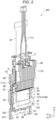
- FIG. 2 is a perspective view showing the light modulation unit 353 as seen from a light incident side
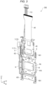
- FIG. 3 is a perspective view showing the light modulation unit 353 as seen from a light exiting side
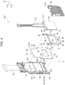
- FIG. 4 is an exploded perspective view showing the light modulation unit 353 as seen from the light incident side
- FIG. 5 is an exploded perspective view showing the light modulation unit 353 as seen from the light exiting side.
- the light modulation unit 353 includes a liquid crystal panel module 4, a holding member 6, a thermoelectric conversion device 71, and a cooler 72.
- the thermoelectric conversion device 71 and the cooler 72 form the light modulation unit 353 and form a temperature adjustment apparatus 7, which will be described later.
- the +Z direction is a traveling direction of light entering the light modulation unit 353.
- the leftward direction when the light modulation unit 353 is seen along the +Z direction so that the +Y direction may coincide with the upward direction is the +X direction.
- the opposite direction to the +X direction is a -X direction
- the opposite direction to the +Y direction is a -Y direction
- the opposite direction to the +Z direction is a -Z direction. That is, the +Z direction with respect to the light modulation unit 353 is the light exiting side of the light modulation unit 353 and the - Z direction with respect to the light modulation unit 353 is the light incident side of the light modulation unit 353.
- an axis along the +X direction or the -X direction is an X-axis
- an axis along the +Y direction or the -Y direction is a Y-axis
- an axis along the +Z direction or the -Z direction is a Z-axis.
- FIG. 6 shows a section of the light modulation unit 353 along the YZ-plane.
- the liquid crystal panel module 4 modulates the entering light, forms an image according to an image signal, and outputs the formed image.
- the liquid crystal panel module 4 includes a liquid crystal panel 41, an FPC (Flexible printed circuits) 42, a holding frame 43, and a thermal diffuser 5.
- the liquid crystal panel module 4 includes a temperature sensor 44.
- the temperature sensor 44 is provided on e.g., the holding frame 43 and detects the temperature of the liquid crystal panel 41.
- the temperature sensor 44 outputs a detection result to a control unit 75 of the temperature adjustment apparatus 7, which will be described later.
- the liquid crystal panel 41 modulates the entering light and outputs the modulated light along the traveling direction of the entering light.
- the liquid crystal panel 41 is a heat source in the light modulation unit 353.
- the liquid crystal panel 41 includes an optical action unit 411 and a light incident-side dustproof substrate 415 and a light exiting-side dustproof substrate 416 sandwiching the optical action unit 411 on the Z-axis.
- the optical action unit 411 has a liquid crystal layer 412 and a counter substrate 413 and a pixel substrate 414 sandwiching the liquid crystal layer 412 on the Z-axis.
- the liquid crystal layer 412 is formed by liquid crystal molecules sealed between the counter substrate 413 and the pixel substrate 414.
- the counter substrate 413 is placed at the light incident side with respect to the liquid crystal layer 412.
- a counter electrode is provided on the surface facing the liquid crystal layer 412.
- the pixel substrate 414 is placed at the light exiting side with respect to the liquid crystal layer 412.
- a plurality of pixel electrodes are provided on the surface facing the liquid crystal layer 412. Note that, as seen from the -Z direction as the light incident side, an area where the plurality of pixel electrodes are placed in the optical action unit 411 is a pixel area PA, and one pixel is formed by an area where each pixel electrode is placed in the pixel area PA.
- the counter substrate 413 and the pixel substrate 414 are coupled to the FPC 42 and change the alignment condition of the liquid crystal molecules forming the liquid crystal layer 412 according to the image signal supplied from the FPC 42. Thereby, the optical action unit 411 modulates the entering light.
- the light incident-side dustproof substrate 415 is a light-transmissive substrate provided in a portion corresponding to the pixel area PA on the light incident surface of the counter substrate 413.
- the light incident-side dustproof substrate 415 is heat-transferably provided to the light incident surface of the counter substrate 413 to cover the pixel area PA.
- the light incident-side dustproof substrate 415 suppresses attachment of dust or the like to the light incident surface of the counter substrate 413 and entry of a shadow of the dust or the like into the image light.
- the thermal diffuser 5 is coupled to the light incident-side dustproof substrate 415.
- a contact portion 54 of the thermal diffuser 5 heat-transferably contacts a light incident surface 415A in the light incident-side dustproof substrate 415.
- the light incident surface 415A is a heat transfer surface transferring heat generated in the optical action unit 411 of the liquid crystal panel 41 to the thermal diffuser 5. That is, the liquid crystal panel module 4 has the liquid crystal panel 41 outputting the entering light and the light incident surface 415A as the heat transfer surface transferring the heat of the liquid crystal panel 41.
- the light exiting-side dustproof substrate 416 is a light-transmissive substrate provided in a portion corresponding to the pixel area PA on the light exiting surface of the pixel substrate 414.
- the light exiting-side dustproof substrate 416 is heat-transferably provided to the light exiting surface of the pixel substrate 414 to cover the pixel area PA.
- the light exiting-side dustproof substrate 416 suppresses direct attachment of dust or the like to the light exiting surface of the pixel substrate 414 and entry of a shadow of the dust or the like into the image light.
- the FPC 42 extends from the counter substrate 413 and the pixel substrate 414 in the + Y direction and is coupled to the above described control apparatus.
- the FPC 42 has a driver circuit 421 driving the optical action unit 411, and the driver circuit 421 applies a drive signal according to the input image signal to the pixel substrate 414.
- the holding frame 43 holds the liquid crystal panel 41 and the FPC 42 and supports the thermal diffuser 5, the holding member 6, the thermoelectric conversion device 71, and the cooler 72. As shown in FIGS. 3 and 5 , the holding frame 43 is formed in a rectangular shape elongated in the +Y direction as seen from the light exiting side. Though not illustrated, the holding frame 43 has an opening portion through which a light entering the liquid crystal panel 41 and a light outputting from the liquid crystal panel 41 pass.
- the holding frame 43 has four through holes 431 penetrating the holding frame 43 along the Z-axis. Though not illustrated, in each of the four through holes 431, an arm portion of a supporting member provided in the light combining system 355 is inserted.
- the supporting member is provided in each of three light incident surfaces into which the color lights modulated by the light modulation units 353 in the light combining system 355, the arm portions are inserted into the through holes 431, and thereby, the light combining system 355 and the three light modulation units 353 are integrated.
- the thermal diffuser 5 receives heat of the liquid crystal panel 41 from the light incident surface 415A of the light incident-side dustproof substrate 415 and diffuses the received heat in the thermal diffuser 5.
- the thermal diffuser 5 is formed substantially in a rectangular shape elongated along the Y-axis as seen from the +Z direction and placed at the light incident side with respect to the liquid crystal panel 41, the FPC 42, and the holding frame 43. Specifically, the thermal diffuser 5 is placed between the liquid crystal panel 41 and the thermoelectric conversion device 71.
- the thermal diffuser 5 includes a first surface 51, a second surface 52, an opening portion 53, the contact portion 54, an extending portion 55, two hole portions 56, and two hole portions 57.
- the first surface 51 is a surface facing the liquid crystal panel 41 in the thermal diffuser 5.
- the first surface 51 is a surface at a light exiting side in the thermal diffuser 5.
- the second surface 52 is a surface at the opposite side to the first surface 51 in the thermal diffuser 5.
- the opening portion 53 passes the light entering the liquid crystal panel 41 in the +Z direction when the thermal diffuser 5 is attached to the holding frame 43. That is, the opening portion 53 is a through hole penetrating the thermal diffuser 5 in the +Z direction.
- the opening portion 53 is formed substantially in a rectangular shape corresponding to the pixel area PA as seen from the light incident side.
- the contact portion 54 is provided on the peripheral edge of the opening portion 53 in the first surface 51.
- the contact portion 54 contacts the light incident surface 415A as the heat transfer surface and receives the heat of the liquid crystal panel 41 from the light incident surface 415A.
- the extending portion 55 is a portion extending in a direction crossing the incident direction of the light from the contact portion 54 to the liquid crystal panel 41 in the thermal diffuser 5. Specifically, the extending portion 55 is a portion extending from the contact portion 54 in a direction away from the pixel area PA outputting the image light in the liquid crystal panel module 4. More specifically, the extending portion 55 is a portion extending from the contact portion 54 in the +Y direction crossing the Z-axis. In the thermal diffuser 5, the heat of the liquid crystal panel 41 received in the contact portion 54 is diffused in the extending portion 55. The heat diffused in the extending portion 55 is absorbed by the thermoelectric conversion device 71 in contact with the second surface 52.
- the two hole portions 56 are provided in the +Y direction with respect to the opening portion 53. Screws SR to be fastened to the holding frame 43 are inserted through the respective two hole portions 56.
- the two hole portions 57 are provided in the -Y direction with respect to the opening portion 53. As shown in FIG. 4 , projections 432 provided on the holding frame 43 are inserted through the respective two hole portions 57. That is, the projections 432 are positioning projections and the two hole portions 57 are positioning holes.
- the thermal diffuser 5 is a vapor chamber VC having a sealed housing VC1 in which a working fluid that can change in a vapor phase and a liquid phase is sealed.
- the first surface 51 is a surface facing the liquid crystal panel 41 in the sealed housing VC1 and the second surface 52 is a surface at the opposite side to the first surface 51 in the sealed housing VC1.
- the contact portion 54 and the extending portion 55 are provided in the sealed housing VC1 and the contact portion 54 is a heat receiving portion receiving the heat of the liquid crystal panel 41 in the sealed housing VC1.
- a partial working fluid of the liquid-phase working fluid sealed within the sealed housing VC1 is gasified by the heat of the liquid crystal panel 41 received in the contact portion 54 and changes to a working fluid in a vapor phase and is diffused within the sealed housing VC1.
- a part of the vapor-phase working fluid transfers the heat to a portion at a lower temperature in the sealed housing VC1.
- the vapor-phase working fluid is condensed and changes to a liquid-phase working fluid.
- the working fluid changed into the liquid phase is moved along the inner surface of the sealed housing VC1 to the heat receiving portion again.
- the portion of the sealed housing VC1 to which the heat is transferred is a heat dissipating portion and the transferred heat is dissipated in the heat dissipating portion.
- the thermoelectric conversion device 71 is provided in the extending portion 55, and the portion in which the thermoelectric conversion device 71 is provided is the heat dissipating portion in the sealed housing VC1.
- the holding member 6 is formed substantially in a rectangular shape.
- the holding member 6 is fixed to the holding frame 43 by the screws SR and holds the light incident-side polarizer 352 shown in FIG. 1 at the light incident side with respect to the liquid crystal panel 41.
- the holding member 6 has an opening portion 61, two arm portions 62, two fixing portions 63, a projecting portion 64, three hole portions 65, and two hole portions 66.
- the opening portion 61 is a rectangular opening portion and provided in a position corresponding to the pixel area PA when the holding member 6 is fixed to the holding frame 43.
- the light output from the light incident-side polarizer 352 in the +Z direction passes through the opening portion 61, further passes through the opening portion 53 of the thermal diffuser 5, and enters the liquid crystal panel 41.
- one arm portion 62 projects from an end part in the +X direction in the holding member 6 in the +Y direction, and the other arm portion 62 projects from an end part in the -X direction in the holding member 6 in the +Y direction.
- one fixing portion 63 is provided in the +X direction with respect to the opening portion 61 and the other fixing portion 63 is provided in the -X direction with respect to the opening portion 61.
- the respective fixing portions 63 project in the -Z direction and the light incident-side polarizer 352 is fixed by an adhesive agent or the like at the light incident side.
- the projecting portion 64 projects from the center along the X-axis in the holding member 6 in the -Y direction.
- the two hole portions 65 are respectively provided in the two arm portions 62 and the other one hole portion 65 is provided in the projecting portion 64.
- the screws SR to be fastened to the holding frame 43 are inserted through the respective hole portions 65 along the +Z direction.
- the two hole portions 66 are provided in corner parts in the -Y direction with respect to the opening portion 61.
- the projections 432 as the positioning projections provided on the holding frame 43 are inserted into the respective two hole portions 66. That is, the two hole portions 66 are positioning holes.
- the holding member 6 is fixed to the holding frame 43 with the thermal diffuser 5 and holds the light incident-side polarizer 352.
- the projector 1 includes the temperature adjustment apparatus 7 adjusting the temperature of the liquid crystal panel 41 of each light modulation unit 353 in addition to the above described configuration.
- the temperature adjustment apparatus 7 includes the thermoelectric conversion device 71 and the cooler 72.
- the cooler 72 is provided in the thermoelectric conversion device 71 and the thermoelectric conversion device 71 is provided in the liquid crystal panel module 4.
- thermoelectric conversion device 71 contacts the liquid crystal panel module 4. Specifically, the thermoelectric conversion device 71 is coupled to the thermal diffuser 5 of the liquid crystal panel module 4, and absorbs heat from the thermal diffuser 5 and dissipates the heat. As shown in FIGS. 4 and 5 , the thermoelectric conversion device 71 has a first surface 711, a second surface 712, and lead wires 713.
- the first surface 711 is a surface facing the thermal diffuser 5 in the thermoelectric conversion device 71. Specifically, the first surface 711 is a surface in contact with the extending portion 55 in the thermoelectric conversion device 71. In other words, the first surface 711 is a surface facing in the +Z direction in the thermoelectric conversion device 71.
- the second surface 712 is a surface at the opposite side to the first surface 711 in the thermoelectric conversion device 71. In other words, the second surface 712 is a surface facing in the -Z direction in the thermoelectric conversion device 71.
- the cooler 72 contacts the second surface 712.
- the lead wires 713 extend from end parts in the +Y direction in the thermoelectric conversion device 71 in the +Y direction.
- the lead wires 713 are coupled to the control unit 75 of the temperature adjustment apparatus 7. That is, the operation of the thermoelectric conversion device 71 is controlled by the control unit 75.
- thermoelectric conversion device 71 actively absorbs the heat transferred from the extending portion 55 in the first surface 711 by electric power supplied from the lead wires 713 and dissipates the absorbed heat from the second surface 712 to the cooler 72.
- the thermoelectric conversion device 71 is a Peltier element. Accordingly, the heat can be supplied from the first surface 711 to the extending portion 55 by inversion of the polarity of the thermoelectric conversion device 71. That is, the thermoelectric conversion device 71 may warm the liquid crystal panel 41 via the thermal diffuser 5. Concurrently, in the thermal diffuser 5, the liquid-phase working fluid near the extending portion 55 changes to the vapor-phase working fluid by the heat supplied from the thermoelectric conversion device 71 and the vapor-phase working fluid is diffused within the sealed housing VC1. Then, a partial working fluid of the vapor-phase working fluid transfers the heat to the contact portion 54 and the heat is supplied from the contact portion 54 to the liquid crystal panel 41.
- the second surface 712 serves as a heat absorbing surface and absorbs heat from the cooler 72.
- the cooler 72 is coupled to the thermoelectric conversion device 71, but not directly coupled to the liquid crystal panel module 4. Further, the thermoelectric conversion device 71 serves as a heat insulating member, and thereby, when the thermoelectric conversion device 71 warms the liquid crystal panel 41, the cooling effect by the thermoelectric conversion device 71 does not act on the liquid crystal panel 41.
- the cooler 72 is coupled to the second surface 712 of the thermoelectric conversion device 71 and dissipates heat transferred from the thermoelectric conversion device 71.
- the cooler 72 is a heat sink having a plurality of fins FN.
- the cooler 72 transfers the heat of the liquid crystal panel 41 transferred from the thermoelectric conversion device 71 to a cooling gas circulating by a drive unit 73 of the temperature adjustment apparatus 7 and dissipates the heat of the liquid crystal panel 41.
- FIG. 7 is a block diagram showing a configuration of a part of the light modulation unit 353 and a configuration of the temperature adjustment apparatus 7.
- the temperature adjustment apparatus 7 includes the drive unit 73, a memory 74, and the control unit 75 in addition to the thermoelectric conversion device 71 and the cooler 72. That is, the thermoelectric conversion device 71 and the cooler 72 form the light modulation unit 353 and form the temperature adjustment apparatus 7, and adjust the temperature of the liquid crystal panel 41 under control of the control unit 75.
- FIG. 8 is a side view showing the light modulation unit 353 and the drive unit 73 as seen from the +X direction.
- the drive unit 73 is provided with respect to each light modulation unit 353 and cools the cooler 72.
- the drive unit 73 includes a cooling fan circulating a cooling gas CA in the cooler 72.
- the operation of the drive unit 73 is controlled by the control unit 75.
- the memory 74 shown in FIG. 7 stores a temperature adjustment program and data for execution of temperature adjustment processing for the liquid crystal panel 41 executed by the control unit 75.
- the data stored by the memory 74 includes thresholds used for the temperature adjustment processing.
- the thresholds stored by the memory 74 are e.g., an upper limit value and a lower limit value of a suitable temperature range of the liquid crystal panel 41.
- the memory 74 stores error information representing occurrence of errors.
- the error information is e.g., an error flag.
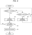
- FIG. 9 is a flowchart showing the temperature adjustment processing executed by the control unit 75.
- the control unit 75 is a controller controlling the temperature of the liquid crystal panel module 4.
- the control unit 75 controls the operation of the thermoelectric conversion device 71 and the drive unit 73 to adjust the temperature of the liquid crystal panel 41. Specifically, the control unit 75 controls the operation of the thermoelectric conversion device 71 and the drive unit 73 based on the temperature of the liquid crystal panel 41 detected by the temperature sensor 44.
- control unit 75 executes the temperature adjustment processing shown in FIG. 9 on the respective light modulation units 353 with reference to the temperature adjustment program stored in the memory 74.
- control unit 75 determines whether the temperature of the liquid crystal panel 41 detected by the temperature sensor 44 is higher than 60 °C (step S1).
- step S1 when a determination that the temperature of the liquid crystal panel 41 is higher than 60 °C is made (step S1: Yes), the control unit 75 executes cooling processing SA.
- FIG. 10 is a flowchart showing the cooling processing SA.
- the cooling processing SA is processing of absorbing heat of the liquid crystal panel 41 transferred to the thermal diffuser 5 via the contact portion 54 by the thermoelectric conversion device 71 and diffused in the thermal diffuser 5. Further, the cooling processing SA is processing of promoting heat dissipation of the heat of the liquid crystal panel 41 by increasing the output of the drive unit 73 and cooling the cooler 72 to which the heat of the liquid crystal panel 41 is transferred. That is, the cooling processing SA includes cooling control of the liquid crystal panel 41 by the thermoelectric conversion device 71 and output increase control of the drive unit 73.
- control unit 75 increases heat absorption output of the thermoelectric conversion device 71 as the Peltier element by 10% (step SA1).
- control unit 75 determines whether the temperature of the liquid crystal panel 41 is equal to or lower than 60 °C (step SA2).
- step SA2 when a determination that the temperature of the liquid crystal panel 41 is equal to or lower than 60 °C is made (step SA2: Yes), the control unit 75 ends the cooling processing SA.
- step SA2 when a determination that the temperature of the liquid crystal panel 41 is not equal to or lower than 60 °C is made (step SA2: No), the control unit 75 determines whether the present heat absorption output of the thermoelectric conversion device 71 reaches 100% (step SA3).
- step SA3 when a determination that the heat absorption output of the thermoelectric conversion device 71 does not reach 100% is made (step SA3: No), the control unit 75 moves the processing to step SA1 and executes step SA1 again. Thereby, the heat absorption output of the thermoelectric conversion device 71 is further increased by 10%.
- steps SA1 to SA3 are processing for cooling control of the liquid crystal panel 41 by the thermoelectric conversion device 71, and the control unit 75 executes steps SA1 to SA3 and increases the heat absorption output to the liquid crystal panel 41 by the thermoelectric conversion device 71 in a stepwise manner.
- step SA3 when a determination that the heat absorption output of the thermoelectric conversion device 71 reaches 100% is made (step SA3: Yes), the control unit 75 increases the output of the drive unit 73 as the cooling fan by 10% (step SA4).
- step SA4 the control unit 75 determines whether the temperature of the liquid crystal panel 41 is equal to or lower than 60 °C (step SA5).
- step SA5 when a determination that the temperature of the liquid crystal panel 41 is equal to or lower than 60 °C is made (step SA5: Yes), the control unit 75 ends the cooling processing SA.
- step SA5 when a determination that the temperature of the liquid crystal panel 41 is not equal to or lower than 60 °C is made (step SA5: No), the control unit 75 determines whether the present output of the drive unit 73 reaches 100% as an output upper limit value (step SA6).
- step SA6 when a determination that the output of the drive unit 73 does not reach 100% is made (step SA6: No), the control unit 75 moves the processing to step SA4 and executes step SA4 again. Thereby, the output of the drive unit 73 is further increased by 10%.
- steps SA4 to SA6 are processing for output increase control of the drive unit 73, and the control unit 75 executes steps SA4 to SA6 and increases the output of the drive unit 73 in a stepwise manner.
- step SA6 when a determination that the output of the drive unit 73 reaches 100% is made (step SA6: Yes), the control unit 75 sets the error information (step SA7). Specifically, at step SA7, the control unit 75 stores the error information representing that the temperature of the liquid crystal panel 41 is out of the suitable temperature range in the memory 74.
- step SA7 the control unit 75 ends the cooling processing SA.
- control unit 75 determines whether an error occurs (step S2). Specifically, the control unit 75 determines whether the error information is stored in the memory 74.
- step S3 the control unit 75 stops the system (step S3).
- the control unit 75 informs a user of the occurrence of an error by lighting of an indicator indicating the occurrence of the error or the like, and turns off the light source 31 and powers off the projector 1. Thereby, the temperature adjustment processing is finished.
- step S2 when a determination that an error does not occur is made (step S2: No), the control unit 75 moves the processing to step S1 and executes the determination processing at step S1 again.
- step S1 when a determination that the temperature of the liquid crystal panel 41 is not higher than 60 °C is made (step S1: No), the control unit 75 determines whether the temperature of the liquid crystal panel 41 is lower than 49 °C (step S4).
- step S4 when a determination that the temperature of the liquid crystal panel 41 is not lower than 49 °C is made (step S4: No), the control unit 75 moves the processing to step S1. In this state, the temperature of the liquid crystal panel 41 takes a value within the suitable temperature range.
- step S4 when a determination that the temperature of the liquid crystal panel 41 is lower than 49 °C is made (step S4: Yes), the control unit 75 executes warming processing SB.
- FIG. 11 is a flowchart showing the warming processing SB.
- the warming processing SB is processing of supplying heat to the thermal diffuser 5 by the thermoelectric conversion device 71 and warming the liquid crystal panel 41 by the heat diffused in the thermal diffuser 5 and transferred to the liquid crystal panel 41 via the contact portion 54. Further, the warming processing SB is processing of decreasing the output of the drive unit 73 to suppress heat dissipation of the heat of the liquid crystal panel 41 and warming the liquid crystal panel 41. That is, the warming processing SB includes warming control of the liquid crystal panel 41 by the thermoelectric conversion device 71 and output decrease control by the drive unit 73.
- the control unit 75 increases warming output of the thermoelectric conversion device 71 as the Peltier element by 10% (step SB1). Concurrently, the control unit 75 sets polarity of the Peltier element to be opposite in the cooling processing SA and the warming processing SB.
- control unit 75 determines whether the temperature of the liquid crystal panel 41 is equal to or higher than 49 °C (step SB2).
- step SB2 when a determination that the temperature of the liquid crystal panel 41 is equal to or higher than 49 °C is made (step SB2: Yes), the control unit 75 ends the warming processing SB.
- step SB2 when a determination that the temperature of the liquid crystal panel 41 is not equal to or higher than 49 °C is made (step SB2: No), the control unit 75 determines whether the present warming output of the thermoelectric conversion device 71 reaches 100% (step SB3).
- step SB3 when a determination that the warming output of the thermoelectric conversion device 71 does not reach 100% is made (step SB3: No), the control unit 75 moves the processing to step SB1 and executes step SB1 again. Thereby, the warming output of the thermoelectric conversion device 71 is further increased by 10%.
- steps SB1 to SB3 are processing for warming control of the liquid crystal panel 41 by the thermoelectric conversion device 71, and the control unit 75 executes steps SB1 to SB3 and increases the warming output to the liquid crystal panel 41 by the thermoelectric conversion device 71 in a stepwise manner.
- step SB3 when a determination that the warming output of the thermoelectric conversion device 71 reaches 100% is made (step SB3: Yes), the control unit 75 decreases the output of the drive unit 73 as the cooling fan by 10% (step SB4). That is, in the warming processing SB, the control unit 75 executes the warming control of the liquid crystal panel 41 by the thermoelectric conversion device 71 in preference to the output decrease control of the drive unit 73.
- step SB4 the control unit 75 determines whether the temperature of the liquid crystal panel 41 is equal to or higher than 49 °C (step SB5).
- step SB5 when a determination that the temperature of the liquid crystal panel 41 is equal to or higher than 49 °C is made (step SB5: Yes), the control unit 75 ends the warming processing SB.
- step SB5 when a determination that the temperature of the liquid crystal panel 41 is not equal to or higher than 49 °C is made (step SB5: No), the control unit 75 determines whether the present output of the drive unit 73 reaches 20% as an output lower limit value (step SB6). Specifically, at step SB6, the control unit 75 determines whether the present output of the drive unit 73 is lower than 20%.
- step SB6 when a determination that the output of the drive unit 73 is not lower than 20% is made (step SB6: No), the control unit 75 moves the processing to step SB4 and executes step SB4 again. Thereby, the output of the drive unit 73 is further decreased by 10%.
- steps SB4 to SB6 are processing for output decrease control of the drive unit 73, and the control unit 75 executes steps SB4 to SB6 and decreases the output of the drive unit 73 in a stepwise manner.
- step SB7 the control unit 75 executes error processing (step SB7).
- the control unit 75 restricts resolution of the image formed by the liquid crystal panel 41. Specifically, the control unit 75 reduces the frame rate of the image formed by the liquid crystal panel 41 and restricts image formation with the maximum resolution that can be formed by the liquid crystal panel 41.
- control unit 75 ends the warming processing SB.
- the control unit 75 returns the processing to step S1 and monitors the temperature of the liquid crystal panel 41.
- the temperature adjustment processing of the liquid crystal panel 41 by the control unit 75 is continuously executed while the power of the projector 1 is on.
- the drive unit 73 as the cooling fan circulating the cooling gas CA in the cooler 72 is driven at the same time as the power on of the projector 1. It is preferable that the drive unit 73 does not only circulate the cooling gas CA in the cooler 72 but also circulates the cooling gas CA in at least one of the polarization conversion element 323 of the homogenization system 32 and the light source 31 using a duct or the like.
- the projector 1 according to the above described embodiment exerts the following effects.
- the temperature adjustment apparatus 7 adjusts the temperature of the liquid crystal panel module 4.
- the temperature adjustment apparatus 7 includes the thermoelectric conversion device 71 in contact with the liquid crystal panel module 4 and the control unit 75 controlling the thermoelectric conversion device 71.
- the liquid crystal panel module 4 includes the liquid crystal panel 41 and the thermal diffuser 5.
- the thermal diffuser 5 has the contact portion 54 in contact with the liquid crystal panel 41 and the extending portion 55 extending from the contact portion 54.
- the thermal diffuser 5 diffuses the received heat.
- the thermoelectric conversion device 71 has the first surface 711 in contact with the extending portion 55 and the second surface 712 at the opposite side to the first surface 711.
- the control unit 75 can execute the cooling processing SA and the warming processing SB.
- the cooling processing SA is the processing of absorbing the heat of the liquid crystal panel 41 transferred to the thermal diffuser 5 via the contact portion 54 by the thermoelectric conversion device 71 and diffused in the thermal diffuser 5.
- the warming processing SB is the processing of supplying heat to the thermal diffuser 5 by the thermoelectric conversion device 71 and warming the liquid crystal panel 41 by the heat diffused in the thermal diffuser 5 and transferred to the liquid crystal panel 41 via the contact portion 54.
- the temperature of the liquid crystal panel 41 may be increased via the thermal diffuser 5 by the thermoelectric conversion device 71 by the control unit 75 executing the warming processing SB. Thereby, responsiveness reduction of the liquid crystal of the liquid crystal panel 41 and image degradation may be suppressed.
- the heat transferred from the liquid crystal panel 41 to the thermal diffuser 5 may be actively absorbed by the thermoelectric conversion device 71 by the control unit 75 executing the cooling processing SA. Thereby, the higher temperature of the liquid crystal panel 41 may be suppressed and the shorter life of the liquid crystal panel 41 may be suppressed.
- the temperature of the liquid crystal panel 41 may be adjusted by the temperature adjustment apparatus 7.
- the temperature adjustment apparatus 7 includes the memory 74 storing the upper limit value and the lower limit value of the suitable temperature range of the liquid crystal panel 41 as thresholds.
- the liquid crystal panel module 4 includes the temperature sensor 44 detecting the temperature.
- the control unit 75 executes one of the cooling processing SA and the warming processing SB based on the comparison result of the detection value by the temperature sensor 44 and the upper limit value and the lower limit value.
- the control unit 75 may appropriately determine which to execute the cooling processing SA and the warming processing SB. Therefore, the temperature adjustment of the liquid crystal panel 41 may be appropriately performed.
- the temperature adjustment apparatus 7 includes the cooler 72 in contact with the second surface 712 and the drive unit 73 cooling the cooler 72. Specifically, the temperature adjustment apparatus 7 includes the drive unit 73 as the cooling fan cooling the cooler 72 in contact with the second surface 712 of the thermoelectric conversion device 71.
- the cooling efficiency of the liquid crystal panel 41 may be increased.
- the warming processing SB includes the warming control of the liquid crystal panel 41 by the thermoelectric conversion device 71 and the output decrease control of the drive unit 73.
- control unit 75 controls the thermoelectric conversion device 71 and the drive unit 73, and thereby, the temperature adjustment of the liquid crystal panel 41 in the warming processing SB may be finely performed.
- the control unit 75 executes the warming control of the liquid crystal panel 41 by the thermoelectric conversion device 71 in preference to the output decrease control of the drive unit 73.
- the warming of the liquid crystal panel 41 by the thermoelectric conversion device 71 may increase the temperature of the liquid crystal panel 41 more quickly than decreasing of the output of the drive unit 73 cooling the cooler 72.
- the liquid crystal panel 41 when the temperature of the liquid crystal panel 41 is lower and when the ambient temperature of the liquid crystal panel 41 is lower, the liquid crystal panel 41 may be quickly warmed.
- the control unit 75 increases the warming output to the liquid crystal panel 41 by the thermoelectric conversion device 71 in a stepwise manner. Specifically, when the temperature of the liquid crystal panel 41 is not equal to or higher than the above described lower limit value, the control unit 75 increases the output of the thermoelectric conversion device 71 in a stepwise manner until the output of the thermoelectric conversion device 71 reaches 100%.
- the liquid crystal panel 41 may be kept within the appropriate temperature range while the power consumption with the warming of the liquid crystal panel 41 is suppressed.
- the control unit 75 decreases the output of the drive unit 73 in a stepwise manner. Specifically, when the temperature of the liquid crystal panel 41 is not equal to or higher than the above described lower limit value, the control unit 75 decreases the output of the drive unit 73 in a stepwise manner until the output of the drive unit 73 becomes lower than 20%.
- the liquid crystal panel 41 may be kept within the appropriate temperature range while the power consumption with the warming of the liquid crystal panel 41 is suppressed.
- control unit 75 includes the cooling control of the liquid crystal panel 41 by the thermoelectric conversion device 71 and the output increase control of the drive unit 73.
- control unit 75 controls the thermoelectric conversion device 71 and the drive unit 73, and thereby, the temperature adjustment of the liquid crystal panel 41 in the cooling processing SA may be finely performed.
- control unit 75 executes the cooling control of the liquid crystal panel 41 by the thermoelectric conversion device 71 in preference to the output increase control of the drive unit 73.
- thermoelectric conversion device 71 may decrease the temperature of the liquid crystal panel 41 more quickly than increasing of the output of the drive unit 73 cooling the cooler 72.
- the liquid crystal panel 41 when the temperature of the liquid crystal panel 41 is higher and when the ambient temperature of the liquid crystal panel 41 is higher, the liquid crystal panel 41 may be quickly cooled.
- the drive unit 73 is the cooling fan cooling the cooler 72 by circulating the cooling gas in the cooler 72. Accordingly, when the temperature of the liquid crystal panel 41 reaches within the suitable temperature range by the cooling control of the thermoelectric conversion device 71, the output of the drive unit 73 is not increased. Therefore, generation of noise including wind noise and drive noise with the output increase of the drive unit 73 as the cooling fan may be suppressed.
- the control unit 75 increases the output of the thermoelectric conversion device 71 in a stepwise manner. Specifically, when the temperature of the liquid crystal panel 41 is not equal to or lower than the above described upper limit value, the control unit 75 increases the output of the thermoelectric conversion device 71 until the output of the thermoelectric conversion device 71 reaches 100%.
- the liquid crystal panel 41 may be easily kept within the appropriate temperature range while the power consumption with the cooling of the liquid crystal panel 41 is suppressed.
- the control unit 75 increases the output of the drive unit 73 in a stepwise manner. Specifically, when the temperature of the liquid crystal panel 41 is not equal to or lower than the above described upper limit value, the control unit 75 increases the output of the drive unit 73 in a stepwise manner until the output of the drive unit 73 reaches 100%.
- the liquid crystal panel 41 may be easily kept within the appropriate temperature range while the power consumption with the cooling of the liquid crystal panel 41 is suppressed.
- the cooler 72 is the heat sink coupled to the second surface 712 of the thermoelectric conversion device 71.
- the drive unit 73 is the fan circulating the cooling wind in the cooler 72 as the heat sink.
- the cooler 72 and the drive unit 73 may be simply formed and the cost of the projector 1 as the electronic apparatus may be reduced.
- the thermoelectric conversion device 71 is the Peltier element.
- the control unit 75 sets the polarity of the Peltier element to be opposite in the cooling processing SA and the warming processing SB.
- control unit 75 controls the polarity of the thermoelectric conversion device 71 as the Peltier element, and thereby, the warming of the liquid crystal panel 41 and the cooling of the liquid crystal panel 41 may be easily switched.
- the control unit 75 is a controller controlling the temperature of the liquid crystal panel 41 of the light modulation unit 353.
- the light modulation unit 353 includes the liquid crystal panel 41, the thermal diffuser 5 in contact with the liquid crystal panel 41, in which the received heat is diffused, and the thermoelectric conversion device 71 in contact with the thermal diffuser 5.
- the control unit 75 is configured to execute the cooling processing SA and the warming processing SB.
- the cooling processing SA is the processing of absorbing the heat of the liquid crystal panel 41 transferred from the liquid crystal panel 41 to the thermal diffuser 5 by the thermoelectric conversion device 71 and diffused in the thermal diffuser 5.
- the warming processing SB is the processing of supplying heat to the thermal diffuser 5 by the thermoelectric conversion device 71 and warming the liquid crystal panel 41 by the heat diffused in the thermal diffuser 5 and transferred to the liquid crystal panel 41.
- FIG. 12 is a flowchart showing warming processing SC as a modification of the warming processing SB.
- the control unit 75 executes the warming control of the liquid crystal panel 41 by the thermoelectric conversion device 71 in preference to the output decrease control of the drive unit 73.
- the control unit 75 may execute e.g., the warming processing SC shown in FIG. 12 in place of the warming processing SB.
- the warming processing SC includes the warming control of the liquid crystal panel 41 by the thermoelectric conversion device 71 and the output decrease control of the drive unit 73 like the warming processing SB.
- the control unit 75 executes the output decrease control of the drive unit 73 in preference to the warming control of the liquid crystal panel 41 by the thermoelectric conversion device 71.
- the control unit 75 executes steps SB4 to SB6 included in the warming processing SB shown in FIG. 11 in preference to steps SB1 to SB3.
- step SB5 in the determination processing at step SB5, when a determination that the temperature of the liquid crystal panel 41 is equal to or higher than 49 °C is made (step SB5: Yes), the control unit 75 ends the warming processing SC.
- step SB6 when a determination that the output of the drive unit 73 is lower than 20% is made (step SB6: Yes), the control unit 75 executes steps SB1 to SB3 included in the warming processing SB shown in FIG. 11 .
- step SB2 in the determination processing at step SB2, when a determination that the temperature of the liquid crystal panel 41 is equal to or higher than 49 °C is made (step SB2: Yes), the control unit 75 ends the warming processing SC.
- step SB3 in the determination processing at step SB3, when a determination that the warming output of the thermoelectric conversion device 71 reaches 100% is made (step SB3: Yes), the control unit 75 executes error processing at step SB7 and ends the warming processing SC.
- the control unit 75 executes the above described warming processing SC in place of the warming processing SB, and thereby, the projector 1 may exert the following effects.
- control unit 75 executes the output decrease control of the drive unit 73 in preference to the warming control of the liquid crystal panel 41 by the thermoelectric conversion device 71.
- thermoelectric conversion device 71 consumes more power than the decreasing of the output of the drive unit 73 cooling the cooler 72.
- the liquid crystal panel 41 may be warmed while the power consumption with warming of the liquid crystal panel 41 is suppressed.
- a projector according to the embodiment has a similar configuration as the projector 1 according to the first embodiment, and different in the configuration of the temperature adjustment apparatus and the configuration of the cooler. Note that, in the following description, the same or substantially the same parts as the above described parts have the same signs and the explanation thereof will be omitted.
- FIG. 13 is a perspective view showing a light modulation unit 353A of the projector according to the embodiment as seen from the light incident side.
- FIG. 14 is an exploded perspective view showing the light modulation unit 353A as seen from the light exiting side.
- FIG. 15 is a block diagram showing a configuration of a temperature adjustment apparatus 7A of the projector according to the embodiment.
- the projector according to the embodiment has the same configurations and functions as the projector 1 according to the first embodiment except that the light modulation unit 353A shown in FIGS. 13 and 14 is provided in place of the light modulation unit 353 and the temperature adjustment apparatus 7A shown in FIG. 15 is provided in place of the temperature adjustment apparatus 7.
- the light modulation unit 353A has the same configuration as the light modulation unit 353 according to the first embodiment except that a cooler 76 is attached in place of the cooler 72. That is, the light modulation unit 353A includes the liquid crystal panel module 4 and the holding member 6, the thermoelectric conversion device 71 contacts the extending portion 55 of the thermal diffuser 5 of the liquid crystal panel module 4 and the cooler 76 contacts the second surface 712 of the thermoelectric conversion device 71.
- the cooler 76 dissipates heat transferred from the thermoelectric conversion device 71 like the cooler 72 according to the first embodiment.
- the cooler 76 includes a cooler main body 761, an inflow tube 762, and an outflow tube 763.
- the cooler main body 761 has a plurality of channels in which the liquid refrigerant can circulate inside and the liquid refrigerant supplied from the inflow tube 762 circulates inside. That is, the cooler 760 is a cold plate in which the liquid refrigerant circulates.
- the cooler main body 761 is formed using a material of a metal having higher thermal conductivity or the like and heat-transferably fixed to the second surface 712. The heat transferred from the second surface 712 to the cooler main body 761 is transferred to the liquid refrigerant circulating within the cooler main body 761. Thereby, the cooler main body 761, i.e., the liquid crystal panel 41 are cooled.
- the inflow tube 762 is a tubular member for the liquid refrigerant to flow into the cooler main body 761.
- the outflow tube 763 is a tubular member for the liquid refrigerant circulated inside the cooler main body 761 to flow out.
- the temperature adjustment apparatus 7A adjusts the temperature of the liquid crystal panel 41 of each light modulation unit 353A like the temperature adjustment apparatus 7 according to the first embodiment.
- the temperature adjustment apparatus 7A includes the thermoelectric conversion device 71, the memory 74, and the cooler 76, and further includes a tank 77, a radiator 78, a drive unit 79, a tubular member 80, and a control unit 81.
- the tubular member 80 is formed so that the liquid refrigerant can circulate inside.
- the tank 77 accumulates the liquid refrigerant.
- the radiator 78 is coupled to the tank 77 via the tubular member 80.
- the radiator 78 cools the liquid refrigerant flowing in from the tank 77.
- the drive unit 79 is coupled to the radiator 78 via the tubular member 80.
- the drive unit 79 is a pump and pressure-feeds the liquid refrigerant cooled in the radiator 78 to the inflow tube 762 of the cooler 76.
- the liquid refrigerant pressure-fed by the drive unit 79 circulates in the cooler 76 and flows into the tank 77.
- the liquid refrigerant flowing into the tank 77 flows into the drive unit 79 again via the radiator 78.
- the control unit 81 controls the thermoelectric conversion device 71 and the drive unit 79 and adjusts the temperature of the liquid crystal panel 41 like the control unit 75 according to the first embodiment. That is, the control unit 81 controls the operation of the thermoelectric conversion device 71 and the drive unit 79 based on the temperature of the liquid crystal panel 41 detected by the temperature sensor 44 of the light modulation unit 353A. Specifically, the control unit 81 executes temperature adjustment processing shown in FIG. 9 on the light modulation unit 353A with reference to the temperature adjustment program stored in the memory 74.
- the control unit 81 executes cooling processing SA.
- the control unit 81 executes steps SA1 to SA3 and increases heat absorption output to the liquid crystal panel 41 by the thermoelectric conversion device 71 in a stepwise manner. Further, the control unit 81 executes steps SA4 to SA6 and increases output of the drive unit 79 in a stepwise manner.
- the control unit 81 ends the cooling processing SA.
- step SA6 when a determination that the output of the drive unit 79 reaches 100% is made (step SA6: Yes), the control unit 81 sets error information at step SA7 and, after ending the cooling processing SA, executes error processing at step S3.
- the control unit 81 executes warming processing SB or warming processing SC.
- the control unit 81 executes steps SB1 to SB3 and increases warming output to the liquid crystal panel 41 by the thermoelectric conversion device 71 in a stepwise manner. Further, the control unit 81 executes steps SB4 to SB6 and decreases output of the drive unit 79 in a stepwise manner.
- the control unit 81 executes steps SB4 to SB6 and decreases output of the drive unit 79 in a stepwise manner. Further, the control unit 81 executes steps SB1 to SB3 and increases warming output to the liquid crystal panel 41 by the thermoelectric conversion device 71 in a stepwise manner.
- the control unit 81 ends the processing.
- the projector according to the embodiment includes the three light modulation units 353A like the projector 1 according to the first embodiment.
- the three light modulation units 353A include a light modulation unit 353AR for red light, a light modulation unit 353AG for green light, and a light modulation unit 353AB for blue light.
- the tank 77, the radiator 78, the drive unit 79, the tubular member 80, and the control unit 81 are placed for the liquid crystal panel 41 of the single light modulation unit 353A. That is, in the above described configuration example of the temperature adjustment apparatus 7, one drive unit 79 is provided for one cooler 76.
- a plurality of coolers 76 may be coupled to a circulation channel and the liquid refrigerant may be circulated by the single drive unit 79 for the respective coolers 76.
- FIG. 16 is a schematic diagram showing another example of the circulation channel of the liquid refrigerant.
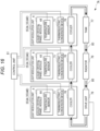
- the inflow tube 762 of the cooler 76 provided in the light modulation unit 353AB is coupled to the drive unit 79, and the outflow tube 763 of the cooler 76 provided in the light modulation unit 353AB is coupled to the inflow tube 762 of the cooler 76 provided in the light modulation unit 353AG.
- the outflow tube 763 of the cooler 76 provided in the light modulation unit 353AG is coupled to the inflow tube 762 of the cooler 76 provided in the light modulation unit 353AR, and the outflow tube 763 of the cooler 76 provided in the light modulation unit 353AR is coupled to the tank 77.
- the liquid refrigerant circulates from the drive unit 79 in the order of the light modulation unit 353AB, the light modulation unit 353AG, and the light modulation unit 353AR.
- the liquid refrigerant circulated in the light modulation unit 353AR circulates the tank 77 and the radiator 78, and then, is delivered to the light modulation unit 353AB by the drive unit 79 again.
- the light modulation unit 353AB entered by the blue light having a wavelength near the wavelength of ultraviolet light is most likely to be deteriorated by high-energy light.
- the amount of green light is larger than the amounts of other color lights, and the light modulation unit 353AG is likely to be deteriorated due to the temperature.
- the liquid refrigerant at the lowest temperature is circulated in the light modulation unit 353AB, the liquid refrigerant circulated in the light modulation unit 353AB is circulated in the light modulation unit 353AG prior to the light modulation unit 353AR, and thereby, the respective light modulation units 353A may be effectively cooled and the deterioration of the respective light modulation units 353A may be suppressed.
- control unit 81 when the control unit 81 executes the above described temperature adjustment processing, the control unit 81 may execute the cooling processing SA and the warming processing SB, SC according to the temperature of the liquid crystal panel 41 at the lowest temperature or the temperature of the liquid crystal panel 41 at the highest temperature of the three liquid crystal panels 41.
- the control unit 81 may execute the temperature adjustment processing of the respective liquid crystal panels 41 and operate the respective thermoelectric conversion devices 71 according to the temperatures of the respective liquid crystal panels 41. That is, the respective thermoelectric conversion devices 71 may be individually controlled. Specifically, when the temperature of the liquid crystal panel 41 is higher than 60 °C, the control unit 81 may execute the cooling processing including steps SA1 to SA3 using the thermoelectric conversion device 71 corresponding to the liquid crystal panel 41, and, when the temperature of the liquid crystal panel 41 is lower than 49 °C, the control unit 81 may execute the warming processing including steps SB1 to SB3 using the thermoelectric conversion device 71 corresponding to the liquid crystal panel 41.
- the control unit 81 may increase the output of the drive unit 79 in a stepwise manner.
- the control unit 81 may decrease the output of the drive unit 79 in a stepwise manner.
- the projector according to the above described embodiment exerts the same effects as the projector 1 according to the first embodiment, and further exerts the following effects.
- the cooler 76 transfers the heat transferred from the second surface 712 of the thermoelectric conversion device 71 to the liquid refrigerant circulating inside.
- the drive unit 79 is the pump circulating the liquid refrigerant in the cooler 76.
- the heat transferred to the cooler 76 by the thermoelectric conversion device 71 may be promptly transferred to the liquid refrigerant. Therefore, even when the amount of generated heat of the liquid crystal panel 41 is higher, the temperature of the liquid crystal panel 41 may be easily decreased.
- the present disclosure is not limited to the above described respective embodiments.
- the present disclosure includes modifications, improvements, etc. within the range in which the purpose of the present disclosure may be achieved.
- FIG. 17 is a sectional view enlarging and showing a part of the light modulation unit 353 including a thermal diffuser 5B as a modification of the thermal diffuser 5 in place of the thermal diffuser 5. Note that, in FIG. 17 , the illustration of the holding frame 43 and the holding member 6 is omitted.
- the thermal diffuser 5 includes the vapor chamber VC having the sealed housing VC1 housing the working fluid.
- the thermal diffuser is not limited to that, but may include a different configuration from the vapor chamber VC.
- the thermal diffuser 5B shown in FIG. 17 may be employed.
- the thermal diffuser 5B includes a supporting member 5B1, a first sheet 5B2, and a second sheet 5B3.
- the supporting member 5B1 is a flat plate-like member formed using a metal such as aluminum and supports the first sheet 5B2 and the second sheet 5B3.
- the supporting member 5B1 has a first surface 5B11 as a surface at the liquid crystal panel 41 side and a second surface 5B12 at the opposite side to the first surface 5B11.
- the first sheet 5B2 is provided on the first surface 5B11 to cover the first surface 5B11 in the +Z direction and the second sheet 5B3 is provided on the second surface 5B12 to cover the second surface 5B12 in the -Z direction.
- the first sheet 5B2 and the second sheet 5B3 are formed using graphite sheets or graphene sheets. That is, the thermal diffuser 5B is a thermal conductor including at least either of the graphite sheets or the graphene sheets.
- the thermal diffuser 5B includes a first surface 5B4, a second surface 5B5, an opening portion 5B6, a contact portion 5B7, and an extending portion 5B8.
- the first surface 5B4 is a surface facing the liquid crystal panel 41 in the thermal diffuser 5B.
- the first surface 5B4 is formed by the first sheet 5B2.
- the second surface 5B5 is a surface at the opposite side to the first surface 5B4 in the thermal diffuser 5B.
- the second surface 5B5 is formed by the second sheet 5B3.
- the opening portion 5B6 is a through hole penetrating the thermal diffuser 5B along the +Z direction and passes the light entering the liquid crystal panel 41 in the +Z direction.
- the opening portion 5B6 is formed substantially in a rectangular shape corresponding to the pixel area PA as seen from the light incident side.
- the contact portion 5B7 is provided on the peripheral edge of the opening portion 5B6 in the first surface 5B4.
- the contact portion 5B7 contacts the light incident surface 415A as the heat transfer surface and receives the heat of the liquid crystal panel 41 from the light incident surface 415A. That is, the contact portion 5B7 is formed by the first sheet 5B2.
- the extending portion 5B8 is a portion extending in a direction crossing the incident direction of the light from the contact portion 5B7 to the liquid crystal panel 41 in the thermal diffuser 5B. Specifically, the extending portion 5B8 is a portion extending from the contact portion 5B7 in the +Y direction crossing the +Z direction.
- the thermoelectric conversion device 71 is coupled to a portion corresponding to the extending portion 5B8 on the second surface 5B5.
- the heat of the liquid crystal panel 41 transferred to the contact portion 5B7 in contact with the light incident surface 415A is diffused in the first sheet 5B2 forming the contact portion 5B7 and transferred to the supporting member 5B1 and diffused in the supporting member 5B1. Further, the heat transferred to the supporting member 5B1 is transferred to the second sheet 5B3 and diffused in the second sheet 5B3.
- the heat diffused by the thermal diffuser 5B is absorbed by the thermoelectric conversion device 71 coupled to the extending portion 5B8.
- the light modulation unit 353A according to the second embodiment can employ the thermal diffuser 5B in place of the thermal diffuser 5.
- the light modulation units 353, 353A including the thermal diffusers 5B in place of the thermal diffusers 5 may exert the same effects as the light modulation units 353, 353A including the thermal diffusers 5 and further have the following effects.
- the thermal diffuser 5B is the thermal conductor including at least either of the graphite sheets or the graphene sheets.
- the graphite sheets and the graphene sheets diffuse the transferred heat within the sheets. Accordingly, the thermal conductor including the sheets is employed as the thermal diffuser 5B, and thereby, the heat transferred from the light incident surface 415A as the heat transfer surface may be easily transferred to the extending portion 5B8 and the heat of the liquid crystal panel 41 transferred to the thermal diffuser 5B may be easily absorbed by the thermoelectric conversion device 71.
- thermoelectric conversion device 71 may be easily transferred from the extending portion 5B8 to the contact portion 5B7 and easily transferred to the liquid crystal panel 41.
- the heat of the liquid crystal panel 41 may be dissipated in the cooler 72, 76 and heat may be easily transferred from the thermoelectric conversion device 71 to the liquid crystal panel 41, and thereby, the temperature of the liquid crystal panel 41 may be easily adjusted.
- the thermal diffuser 5B includes the supporting member 5B1, the first sheet 5B2, and the second sheet 5B3.
- the configuration is not limited to that.
- the thermal diffuser 5B may include only one of the first sheet 5B2 and the second sheet 5B3. Further, if the liquid crystal panel 41 and the thermoelectric conversion device 71 can be coupled, the heat diffuser may have only one sheet and the supporting member 5B1 may be omitted.
- the control unit 75, 81 executes one processing of the cooling processing SA and the warming processing SB, SC based on the comparison result between the detection result of the temperature sensor 44 detecting the temperature of the liquid crystal panel 41 and the thresholds stored in the memory 74.
- the control unit 75, 81 may determine the processing to execute based on the temperature inside of the exterior housing 2 or the temperature outside of the exterior housing 2.
- the control unit 75, 81 may determine the processing of the cooling processing SA and the warming processing SB, SC to execute based on an elapsed time from the start of the lighting of the light source 31. That is, the index for determination of the processing to be executed of the cooling processing SA and the warming processing SB, SC by the control unit 75, 81 is not limited to the temperature of the liquid crystal panel 41.
- the liquid crystal panel module 4 does not necessarily include the temperature sensor 44.
- the cooling processing SA includes the output increase control of the drive unit 73 by the control unit 75 in addition to the cooling control of the thermoelectric conversion device 71 by the control unit 75.
- the cooling processing SA may include the cooling control of the thermoelectric conversion device 71 by the control unit 75, but not include the output increase control of the drive unit 73 by the control unit 75.
- the cooling processing SA includes the output increase control of the drive unit 79 by the control unit 81 in addition to the cooling control of the thermoelectric conversion device 71 by the control unit 81.
- the cooling processing SA may include the cooling control of the thermoelectric conversion device 71 by the control unit 81, but not include the output increase control of the drive unit 79 by the control unit 81.
- the control unit 75 increases the output of the thermoelectric conversion device 71 in a stepwise manner and increases the output of the drive unit 73 in a stepwise manner.
- the control unit 81 increases the output of the thermoelectric conversion device 71 in a stepwise manner and increases the output of the drive unit 79 in a stepwise manner.
- the configuration is not limited to that.
- the output of the thermoelectric conversion device 71 is not necessarily increased in a stepwise manner and the output of the drive unit 73, 79 is not necessarily increased in a stepwise manner.
- the cooling control of the liquid crystal panel 41 by the thermoelectric conversion device 71 is performed in preference to the output increase control of the drive unit 73, 79.
- the configuration is not limited to that.
- the output increase control of the drive unit 73, 79 may be performed in preference to the cooling control of the liquid crystal panel 41 by the thermoelectric conversion device 71.
- the warming processing SB, SC includes the output decrease control of the drive unit 73 by the control unit 75 in addition to the warming control of the thermoelectric conversion device 71 by the control unit 75.
- the warming processing SB, SC may include the warming control of the thermoelectric conversion device 71 by the control unit 75, but not include the output decrease control of the drive unit 73 by the control unit 75.
- the warming processing SB, SC includes the output decrease control of the drive unit 79 by the control unit 81 in addition to the warming control of the thermoelectric conversion device 71 by the control unit 81.
- the warming processing SB, SC may include the warming control of the thermoelectric conversion device 71 by the control unit 81, but not include the output decrease control of the drive unit 79 by the control unit 81.
- the control unit 75 increases the output of the thermoelectric conversion device 71 in a stepwise manner and increases the output of the drive unit 73 in a stepwise manner.
- the control unit 81 increases the output of the thermoelectric conversion device 71 in a stepwise manner and increases the output of the drive unit 79 in a stepwise manner.
- the configuration is not limited to that.
- the output of the thermoelectric conversion device 71 is not necessarily increased in a stepwise manner and the output of the drive unit 73, 79 is not necessarily increased in a stepwise manner.
- the cooler 72 is the heat sink.
- the cooler 76 is formed so that the liquid refrigerant can be circulated.
- the cooler is not limited to the above described configurations.
- the temperature adjustment apparatus 7 does not necessarily include the cooler 72 and the drive unit 73, and the temperature adjustment apparatus 7A does not necessarily include the cooler 76 and the drive unit 79.
- the thermoelectric conversion device 71 is the Peltier element.
- the control unit 75, 81 sets the polarity of the thermoelectric conversion devices 71 to be opposite when executing the cooling processing SA and absorbing heat from the liquid crystal panel 41 and when executing the warming processing SB, SC and warming the liquid crystal panel 41.
- the configuration is not limited to that.
- the thermoelectric conversion device 71 may include, not limited to the Peltier element, but another configuration as long as the device may perform heat absorption and warming of the liquid crystal panel 41.
- the projector includes the three light modulation units 353, 353A including the liquid crystal panel modules 4.
- the three light modulation units 353 include the light modulation unit 353R for red light, the light modulation unit 353G for green light, and the light modulation unit 353B for blue light.
- the three light modulation units 353A include the light modulation unit 353AR for red light, the light modulation unit 353AG for green light, and the light modulation unit 353AB for blue light.
- the configuration is not limited to that.
- the projector according to the present disclosure may include two or less or four or more light modulation units 353, 353A.
- the projector 1 according to the present disclosure may include only one liquid crystal panel module 4.
- the liquid crystal panel module 4 modulates the entering light by the liquid crystal panel 41 and outputs the modulated light along the incident direction of the light to the liquid crystal panel 41. That is, the liquid crystal panel module 4 is a transmissive liquid crystal panel module. However, the configuration is not limited to that.
- the liquid crystal panel module according to the present disclosure may be a reflective liquid crystal panel module modulating the entering light by the liquid crystal panel and outputs the modulated light in the opposite direction to the incident direction of the light to the liquid crystal panel.
- the light incident surface 415A in the light incident-side dustproof substrate 415 of the liquid crystal panel 41 is the heat transfer surface being in contact with the contact portion 54, 5B7 of the thermal diffuser 5, 5B and transferring the heat of the liquid crystal panel 41 to the thermal diffuser 5, 5B.
- Another portion than the light incident surface 415A may be the heat transfer surface in the liquid crystal panel 41.
- a side surface crossing the light incident surface in at least one substrate of the counter substrate 413, the pixel substrate 414, the light incident-side dustproof substrate 415, and the light exiting-side dustproof substrate 416 may be the heat transfer surface.
- the contact portion 54, 5B7 of the thermal diffuser 5, 5B does not necessarily directly contact the liquid crystal panel 41.
- the contact portion 54, 5B7 may contact a heat transfer member heat-transferably coupled to the liquid crystal panel 41.
- thermoelectric conversion device 71 in contact with the extending portion 55, 5B8 and the cooler 72, 76 in contact with the second surface 712 of the thermoelectric conversion device 71.
- the thermal diffuser 5, 5B does not necessarily have the opening portion 53, 5B6.
- the thermal diffuser 5, 5B, the thermoelectric conversion device 71, and the cooler 72, 76 may be placed at the light exiting side with respect to the liquid crystal panel 41.
- the projector is exemplified as an electronic apparatus including the temperature adjustment apparatus 7, 7A adjusting the temperature of the liquid crystal panel 41 of the liquid crystal panel module 4 and the control unit 75, 81 as the controller.
- the configuration is not limited to that.
- the electronic apparatus including the temperature adjustment apparatus 7, 7A and the control unit 75, 81 of the present disclosure is not limited to the projector, but may be an electronic apparatus including another configuration.
- the electronic apparatus includes e.g., a display apparatus.
- a temperature adjustment apparatus adjusting a temperature of a liquid crystal panel module includes a thermoelectric conversion device in contact with the liquid crystal panel module, and a control unit controlling the thermoelectric conversion device, wherein the liquid crystal panel module includes a liquid crystal panel, and a thermal diffuser having a contact portion in contact with the liquid crystal panel and an extending portion extending from the contact portion and diffusing received heat, the thermoelectric conversion device has a first surface in contact with the extending portion, and a second surface at an opposite side to the first surface, and the control unit is configured to execute warming processing of supplying heat to the thermal diffuser using the thermoelectric conversion device and warming the liquid crystal panel by the heat diffused in the thermal diffuser and transferred to the liquid crystal panel via the contact portion, and cooling processing of absorbing the heat of the liquid crystal panel transferred to the thermal diffuser by the thermoelectric conversion device via the contact portion and diffused in the thermal diffuser.
- the temperature of the liquid crystal panel may be increased via the thermal diffuser by the thermoelectric conversion device by the control unit executing the warming processing. Thereby, responsiveness reduction of liquid crystal of the liquid crystal panel and image degradation may be suppressed.
- the heat transferred from the liquid crystal panel to the thermal diffuser may be actively absorbed by the thermoelectric conversion device by the control unit executing the cooling processing. Thereby, the higher temperature of the liquid crystal panel may be suppressed and the shorter life of the liquid crystal panel may be suppressed.
- the temperature of the liquid crystal panel may be adjusted by the temperature adjustment apparatus.
- the temperature adjustment apparatus further includes a memory storing a threshold, wherein the liquid crystal panel module includes a temperature sensor detecting the temperature, and the control unit executes one processing of the warming processing and the cooling processing based on a comparison result between a detection value by the temperature sensor and the threshold.
- control unit may appropriately determine which to execute the warming processing and the cooling processing by the comparison between the detection value by the temperature sensor and the threshold stored in the memory. Therefore, the temperature adjustment of the liquid crystal panel may be appropriately performed. Appendix 3
- the temperature adjustment apparatus further includes a cooler in contact with the second surface, and a drive unit cooling the cooler.
- cooling efficiency of the liquid crystal panel may be increased.
- the warming processing includes warming control of the liquid crystal panel by the thermoelectric conversion device, and output decrease control of the drive unit.
- control unit controls the thermoelectric conversion device and the drive unit, and thereby, the temperature adjustment of the liquid crystal panel in the warming processing may be finely performed.
- control unit executes the warming control of the liquid crystal panel by the thermoelectric conversion device in preference to the output decrease control of the drive unit in the warming processing.
- the warming of the liquid crystal panel by the thermoelectric conversion device may increase the temperature of the liquid crystal panel more quickly than decreasing of the output of the drive unit cooling the cooler.
- the liquid crystal panel when the temperature of the liquid crystal panel is lower and when the ambient temperature of the liquid crystal panel is lower, the liquid crystal panel may be quickly warmed.
- control unit executes the output decrease control of the drive unit in preference to the warming control of the liquid crystal panel by the thermoelectric conversion device in the warming processing.
- thermoelectric conversion device tends to consume more power than the decreasing of the output of the drive unit cooling the cooler.
- the liquid crystal panel may be warmed while the power consumption with warming of the liquid crystal panel is suppressed.
- control unit increases warming output to the liquid crystal panel by the thermoelectric conversion device in a stepwise manner in the warming processing.
- the liquid crystal panel may be easily kept within an appropriate temperature range while the power consumption with the warming of the liquid crystal panel is suppressed.
- control unit decreases output of the drive unit in a stepwise manner in the warming processing.
- the liquid crystal panel may be easily kept within the appropriate temperature range while the power consumption with the warming of the liquid crystal panel is suppressed.
- control unit includes cooling control of the liquid crystal panel by the thermoelectric conversion device and output increase control of the drive unit in the cooling processing.
- control unit controls the thermoelectric conversion device and the drive unit, and thereby, the temperature adjustment of the liquid crystal panel in the cooling processing may be finely performed.
- control unit executes the cooling control of the liquid crystal panel by the thermoelectric conversion device in preference to the output increase control of the drive unit in the cooling processing.
- thermoelectric conversion device may decrease the temperature of the liquid crystal panel more quickly than increasing of the output of the drive unit cooling the cooler.
- the liquid crystal panel when the temperature of the liquid crystal panel is higher and when the ambient temperature of the liquid crystal panel is higher, the liquid crystal panel may be quickly cooled.
- control unit increases output of the thermoelectric conversion device in a stepwise manner in the cooling processing.
- the liquid crystal panel may be easily kept within the appropriate temperature range while the power consumption with the cooling of the liquid crystal panel is suppressed.
- control unit increases output of the drive unit in a stepwise manner in the cooling processing.
- the liquid crystal panel may be easily kept within the appropriate temperature range while the power consumption with the cooling of the liquid crystal panel is suppressed.
- the cooler is a heat sink coupled to the second surface, and the drive unit is a fan circulating cooling wind in the heat sink.
- the cooler and the drive unit may be simply formed and the cost may be reduced.
- the cooler transfers heat transferred from the second surface to a liquid refrigerant circulating inside, and the drive unit is a pump circulating the liquid refrigerant in the cooler.
- the heat transferred to the cooler by the thermoelectric conversion device may be promptly transferred to the liquid refrigerant. Therefore, even when the amount of generated heat of the liquid crystal panel is higher, the temperature of the liquid crystal panel may be easily decreased.
- thermoelectric conversion device is a Peltier element
- control unit sets polarity of the Peltier element to be opposite in the warming processing and the cooling processing.
- control unit controls the polarity of the Peltier element, and thereby, the warming of the liquid crystal panel and the cooling of the liquid crystal panel may be easily switched.
- a control apparatus controlling a temperature of a liquid crystal panel of a light modulation unit including the liquid crystal panel, a thermal diffuser in contact with the liquid crystal panel and diffusing received heat inside, and a thermoelectric conversion device in contact with the thermal diffuser, configured to execute warming processing of supplying heat to the thermal diffuser using the thermoelectric conversion device and warming the liquid crystal panel by the heat diffused in the thermal diffuser and transferred to the liquid crystal panel, and cooling processing of absorbing the heat of the liquid crystal panel transferred from the liquid crystal panel to the thermal diffuser by the thermoelectric conversion device and diffused in the thermal diffuser.
Landscapes
- Physics & Mathematics (AREA)
- General Physics & Mathematics (AREA)
- Nonlinear Science (AREA)
- Liquid Crystal (AREA)
- Chemical & Material Sciences (AREA)
- Crystallography & Structural Chemistry (AREA)
- Optics & Photonics (AREA)
- Mathematical Physics (AREA)
- Engineering & Computer Science (AREA)
- Automation & Control Theory (AREA)
- Projection Apparatus (AREA)
- Transforming Electric Information Into Light Information (AREA)
- Video Image Reproduction Devices For Color Tv Systems (AREA)
Abstract
Description
- The present application is based on, and claims priority from
JP Application Serial Number 2022-126685, filed August 8, 2022 - The present disclosure relates to a temperature adjustment apparatus and a control appa ratus.
- In related art, a projector forming an image according to image information and projecting the formed image is known (for example, see
JP-A-2015-108697 - The projector disclosed in
JP-A-2015-108697 - As described above, in the projector disclosed in
JP-A-2015-108697 - However, the specific heat of the liquid refrigerant is higher, and it takes time to decrease the temperature of the liquid refrigerant to a temperature suitable for cooling of the heat source. Accordingly, in the configuration disclosed in
JP-A-2015-108697 - On the other hand, when the temperature of the liquid crystal panel is lower, responsiveness of liquid crystal becomes lower. Accordingly, when the temperature of the liquid crystal panel is lower, it may be possible that image formation by the liquid crystal panel is not appropriately performed until the temperature of the liquid crystal panel becomes higher by entry of light or the like.
- Due to these problems, a configuration that can adjust the temperature of the liquid crystal panel is desired.
- A temperature adjustment apparatus according to a first aspect of the present disclosure is a temperature adjustment apparatus adjusting a temperature of a liquid crystal panel module, including a thermoelectric conversion device in contact with the liquid crystal panel module, and a control unit controlling the thermoelectric conversion device, wherein the liquid crystal panel module includes a liquid crystal panel, and a thermal diffuser having a contact portion in contact with the liquid crystal panel and an extending portion extending from the contact portion and diffusing received heat, the thermoelectric conversion device has a first surface in contact with the extending portion, and a second surface at an opposite side to the first surface, and the control unit is configured to execute warming processing of supplying heat to the thermal diffuser using the thermoelectric conversion device and warming the liquid crystal panel by the heat diffused in the thermal diffuser and transferred to the liquid crystal panel via the contact portion, and cooling processing of absorbing the heat of the liquid crystal panel transferred to the thermal diffuser by the thermoelectric conversion device via the contact portion and diffused in the thermal diffuser.
- A control apparatus according to a second aspect of the present disclosure is a control apparatus controlling a temperature of a liquid crystal panel of a light modulation unit including the liquid crystal panel, a thermal diffuser in contact with the liquid crystal panel and diffusing received heat inside, and a thermoelectric conversion device in contact with the thermal diffuser, configured to execute warming processing of supplying heat to the thermal diffuser using the thermoelectric conversion device and warming the liquid crystal panel by the heat diffused in the thermal diffuser and transferred to the liquid crystal panel, and cooling processing of absorbing the heat of the liquid crystal panel transferred from the liquid crystal panel to the thermal diffuser by the thermoelectric conversion device and diffused in the thermal diffuser.
-
-
FIG. 1 is a schematic diagram showing a configuration of a projector in a first embodiment. -
FIG. 2 is a perspective view showing a light modulation unit in the first embodiment. -
FIG. 3 is a perspective view showing the light modulation unit in the first embodiment. -
FIG. 4 is an exploded perspective view showing the light modulation unit in the first embodiment. -
FIG. 5 is an exploded perspective view showing the light modulation unit in the first embodiment. -
FIG. 6 is a sectional view showing the light modulation unit in the first embodiment. -
FIG. 7 is a block diagram showing a configuration of a part of the light modulation unit and a configuration of a temperature adjustment apparatus in the first embodiment. -
FIG. 8 is a side view showing the light modulation unit and a drive unit in the first embodiment. -
FIG. 9 is a flowchart showing temperature adjustment processing in the first embodiment. -
FIG. 10 is a flowchart showing cooling processing in the first embodiment. -
FIG. 11 is a flowchart showing warming processing in the first embodiment. -
FIG. 12 is a flowchart showing a modification of the warming processing in the first embodiment. -
FIG. 13 is a perspective view showing a light modulation unit of a projector in a second embodiment. -
FIG. 14 is an exploded perspective view showing the light modulation unit in the second embodiment. -
FIG. 15 is a block diagram showing a configuration of a temperature adjustment apparatus in the second embodiment. -
FIG. 16 is a schematic diagram showing another example of a circulation channel of a liquid refrigerant in the second embodiment. -
FIG. 17 is a sectional view showing a modification of a thermal diffuser in the first and second embodiments. - As below, a first embodiment of the present disclosure will be explained with reference to the drawings.
-
FIG. 1 is a schematic diagram showing a configuration of aprojector 1 according to the embodiment. - The
projector 1 according to the embodiment is an image display apparatus modulating a light output from alight source 31 provided inside, forming an image light according to image information, and enlarges and projects the formed image light on a projected surface such as a screen. Theprojector 1 is an example of an electronic apparatus of the present disclosure. - As shown in
FIG. 1 , theprojector 1 includes anexterior housing 2 and animage projection apparatus 3 housed in theexterior housing 2. - The
image projection apparatus 3 forms an image light according to input image information and projects the formed image light. Theimage projection apparatus 3 includes thelight source 31, ahomogenization system 32, acolor separation system 33, arelay system 34, animage forming device 35, anoptical component housing 36, and a projectionoptical device 37. - The
light source 31 outputs an illumination light to thehomogenization system 32. As a configuration of thelight source 31, a configuration having e.g., a solid-state light source outputting a blue light as an excitation light and a wavelength conversion element converting at least a part of the blue light output from the solid-state light source into fluorescence containing a green light and a red light may be exemplified. Note that, as another configuration of thelight source 31, a configuration having a light source lamp such as a super high-pressure mercury lamp or a configuration having light emitting devices individually outputting a blue light, a green light, and a red light may be exemplified. - The
homogenization system 32 homogenizes the light output from thelight source 31. The homogenized light illuminates a modulation area of alight modulation unit 353, which will be described later, via thecolor separation system 33 and therelay system 34. Thehomogenization system 32 includes twolens arrays polarization conversion element 323, and asuperimposing lens 324. - The
color separation system 33 separates the light entering from thehomogenization system 32 into respective color lights of red, green, and blue. Thecolor separation system 33 includes twodichroic mirrors reflection mirror 333 reflecting the blue light separated by thedichroic mirror 331. - The
relay system 34 is provided in an optical path of the red light longer than optical paths of the other color lights and suppresses a loss of the red light. Therelay system 34 includes a light incident-side lens 341, arelay lens 343, andreflection mirrors relay system 34. However, for example, a color light having an optical path longer than the other color lights may be a blue light and the blue light may be guided to therelay system 34. - The
image forming device 35 modulates the respective entered color lights of red, green, and blue, combines the respective modulated color lights, and forms an image light. Theimage forming device 35 has threefield lenses 351 provided according to the entered color lights, three light incident-side polarizers 352, threelight modulation units 353, three light exiting-side polarizers 354, and onelight combining system 355. - The
light modulation unit 353 modulates the light output from thelight source 31 based on an image signal. Specifically, thelight modulation unit 353 modulates the color light entering from the light incident-side polarizer 352 according to the image signal and outputs the modulated color light. The threelight modulation units 353 include alight modulation unit 353R for red light, alight modulation unit 353G for green light, and alight modulation unit 353B for blue light. The configuration of thelight modulation unit 353 will be descried later in detail. - The
light combining system 355 combines the three color lights modulated by thelight modulation units light combining system 355 enters the projectionoptical device 37. In the embodiment, thelight combining system 355 includes a cross dichroic prism having a substantially rectangular parallelepiped shape, however, may include a plurality of dichroic mirrors. - The
optical component housing 36 houses the above describedhomogenization system 32,color separation system 33,relay system 34, andimage forming device 35 inside. Note that an optical axis Ax in design is set for theimage projection apparatus 3, and theoptical component housing 36 holds thehomogenization system 32, thecolor separation system 33, therelay system 34, and theimage forming device 35 in predetermined positions on the optical axis Ax. Thelight source 31 and the projectionoptical device 37 are placed in predetermined positions on the optical axis Ax. - The projection
optical device 37 projects the image light entering from theimage forming device 35 on a projected surface such as a screen. The projectionoptical device 37 may be e.g., an assembled lens including a plurality of lenses (not shown) and alens tube 371 housing the plurality of lenses. -
FIG. 2 is a perspective view showing thelight modulation unit 353 as seen from a light incident side,FIG. 3 is a perspective view showing thelight modulation unit 353 as seen from a light exiting side,FIG. 4 is an exploded perspective view showing thelight modulation unit 353 as seen from the light incident side, andFIG. 5 is an exploded perspective view showing thelight modulation unit 353 as seen from the light exiting side. - As shown in
FIGS. 2 to 5 , thelight modulation unit 353 includes a liquidcrystal panel module 4, a holdingmember 6, athermoelectric conversion device 71, and a cooler 72. Thethermoelectric conversion device 71 and the cooler 72 form thelight modulation unit 353 and form atemperature adjustment apparatus 7, which will be described later. - In the following description, three directions orthogonal to one another are a +X direction, a +Y direction, and a +Z direction. In the embodiment, the +Z direction is a traveling direction of light entering the
light modulation unit 353. The leftward direction when thelight modulation unit 353 is seen along the +Z direction so that the +Y direction may coincide with the upward direction is the +X direction. Though not illustrated, the opposite direction to the +X direction is a -X direction, the opposite direction to the +Y direction is a -Y direction, and the opposite direction to the +Z direction is a -Z direction. That is, the +Z direction with respect to thelight modulation unit 353 is the light exiting side of thelight modulation unit 353 and the - Z direction with respect to thelight modulation unit 353 is the light incident side of thelight modulation unit 353. - Further, an axis along the +X direction or the -X direction is an X-axis, an axis along the +Y direction or the -Y direction is a Y-axis, and an axis along the +Z direction or the -Z direction is a Z-axis.
-
FIG. 6 shows a section of thelight modulation unit 353 along the YZ-plane. - The liquid
crystal panel module 4 modulates the entering light, forms an image according to an image signal, and outputs the formed image. As shown inFIG. 6 , the liquidcrystal panel module 4 includes aliquid crystal panel 41, an FPC (Flexible printed circuits) 42, a holdingframe 43, and athermal diffuser 5. In addition, as shown inFIG. 7 , which will be described later, the liquidcrystal panel module 4 includes atemperature sensor 44. - The
temperature sensor 44 is provided on e.g., the holdingframe 43 and detects the temperature of theliquid crystal panel 41. Thetemperature sensor 44 outputs a detection result to acontrol unit 75 of thetemperature adjustment apparatus 7, which will be described later. - The
liquid crystal panel 41 modulates the entering light and outputs the modulated light along the traveling direction of the entering light. Theliquid crystal panel 41 is a heat source in thelight modulation unit 353. Theliquid crystal panel 41 includes anoptical action unit 411 and a light incident-side dustproof substrate 415 and a light exiting-side dustproof substrate 416 sandwiching theoptical action unit 411 on the Z-axis. - The
optical action unit 411 has aliquid crystal layer 412 and acounter substrate 413 and apixel substrate 414 sandwiching theliquid crystal layer 412 on the Z-axis. - The
liquid crystal layer 412 is formed by liquid crystal molecules sealed between thecounter substrate 413 and thepixel substrate 414. - The
counter substrate 413 is placed at the light incident side with respect to theliquid crystal layer 412. On thecounter substrate 413, a counter electrode is provided on the surface facing theliquid crystal layer 412. - The
pixel substrate 414 is placed at the light exiting side with respect to theliquid crystal layer 412. On thepixel substrate 414, a plurality of pixel electrodes are provided on the surface facing theliquid crystal layer 412. Note that, as seen from the -Z direction as the light incident side, an area where the plurality of pixel electrodes are placed in theoptical action unit 411 is a pixel area PA, and one pixel is formed by an area where each pixel electrode is placed in the pixel area PA. - The
counter substrate 413 and thepixel substrate 414 are coupled to theFPC 42 and change the alignment condition of the liquid crystal molecules forming theliquid crystal layer 412 according to the image signal supplied from theFPC 42. Thereby, theoptical action unit 411 modulates the entering light. - The light incident-
side dustproof substrate 415 is a light-transmissive substrate provided in a portion corresponding to the pixel area PA on the light incident surface of thecounter substrate 413. When the liquidcrystal panel module 4 is seen from the -Z direction, the light incident-side dustproof substrate 415 is heat-transferably provided to the light incident surface of thecounter substrate 413 to cover the pixel area PA. The light incident-side dustproof substrate 415 suppresses attachment of dust or the like to the light incident surface of thecounter substrate 413 and entry of a shadow of the dust or the like into the image light. - Note that the
thermal diffuser 5 is coupled to the light incident-side dustproof substrate 415. Specifically, acontact portion 54 of thethermal diffuser 5 heat-transferably contacts alight incident surface 415A in the light incident-side dustproof substrate 415. Thelight incident surface 415A is a heat transfer surface transferring heat generated in theoptical action unit 411 of theliquid crystal panel 41 to thethermal diffuser 5. That is, the liquidcrystal panel module 4 has theliquid crystal panel 41 outputting the entering light and thelight incident surface 415A as the heat transfer surface transferring the heat of theliquid crystal panel 41. - The light exiting-
side dustproof substrate 416 is a light-transmissive substrate provided in a portion corresponding to the pixel area PA on the light exiting surface of thepixel substrate 414. When the liquidcrystal panel module 4 is seen from the +Z direction, the light exiting-side dustproof substrate 416 is heat-transferably provided to the light exiting surface of thepixel substrate 414 to cover the pixel area PA. The light exiting-side dustproof substrate 416 suppresses direct attachment of dust or the like to the light exiting surface of thepixel substrate 414 and entry of a shadow of the dust or the like into the image light. - As shown in
FIG. 6 , theFPC 42 extends from thecounter substrate 413 and thepixel substrate 414 in the + Y direction and is coupled to the above described control apparatus. TheFPC 42 has adriver circuit 421 driving theoptical action unit 411, and thedriver circuit 421 applies a drive signal according to the input image signal to thepixel substrate 414. - The holding
frame 43 holds theliquid crystal panel 41 and theFPC 42 and supports thethermal diffuser 5, the holdingmember 6, thethermoelectric conversion device 71, and the cooler 72. As shown inFIGS. 3 and5 , the holdingframe 43 is formed in a rectangular shape elongated in the +Y direction as seen from the light exiting side. Though not illustrated, the holdingframe 43 has an opening portion through which a light entering theliquid crystal panel 41 and a light outputting from theliquid crystal panel 41 pass. The holdingframe 43 has four throughholes 431 penetrating the holdingframe 43 along the Z-axis. Though not illustrated, in each of the four throughholes 431, an arm portion of a supporting member provided in thelight combining system 355 is inserted. The supporting member is provided in each of three light incident surfaces into which the color lights modulated by thelight modulation units 353 in thelight combining system 355, the arm portions are inserted into the throughholes 431, and thereby, thelight combining system 355 and the threelight modulation units 353 are integrated. - The
thermal diffuser 5 receives heat of theliquid crystal panel 41 from thelight incident surface 415A of the light incident-side dustproof substrate 415 and diffuses the received heat in thethermal diffuser 5. As shown inFIGS. 4 and5 , thethermal diffuser 5 is formed substantially in a rectangular shape elongated along the Y-axis as seen from the +Z direction and placed at the light incident side with respect to theliquid crystal panel 41, theFPC 42, and the holdingframe 43. Specifically, thethermal diffuser 5 is placed between theliquid crystal panel 41 and thethermoelectric conversion device 71. Thethermal diffuser 5 includes afirst surface 51, asecond surface 52, an openingportion 53, thecontact portion 54, an extendingportion 55, twohole portions 56, and twohole portions 57. - The
first surface 51 is a surface facing theliquid crystal panel 41 in thethermal diffuser 5. In other words, thefirst surface 51 is a surface at a light exiting side in thethermal diffuser 5. - The
second surface 52 is a surface at the opposite side to thefirst surface 51 in thethermal diffuser 5. The holdingmember 6 and thethermoelectric conversion device 71, which will be described later, contact thesecond surface 52. - The opening
portion 53 passes the light entering theliquid crystal panel 41 in the +Z direction when thethermal diffuser 5 is attached to the holdingframe 43. That is, the openingportion 53 is a through hole penetrating thethermal diffuser 5 in the +Z direction. The openingportion 53 is formed substantially in a rectangular shape corresponding to the pixel area PA as seen from the light incident side. - The
contact portion 54 is provided on the peripheral edge of the openingportion 53 in thefirst surface 51. Thecontact portion 54 contacts thelight incident surface 415A as the heat transfer surface and receives the heat of theliquid crystal panel 41 from thelight incident surface 415A. - The extending
portion 55 is a portion extending in a direction crossing the incident direction of the light from thecontact portion 54 to theliquid crystal panel 41 in thethermal diffuser 5. Specifically, the extendingportion 55 is a portion extending from thecontact portion 54 in a direction away from the pixel area PA outputting the image light in the liquidcrystal panel module 4. More specifically, the extendingportion 55 is a portion extending from thecontact portion 54 in the +Y direction crossing the Z-axis. In thethermal diffuser 5, the heat of theliquid crystal panel 41 received in thecontact portion 54 is diffused in the extendingportion 55. The heat diffused in the extendingportion 55 is absorbed by thethermoelectric conversion device 71 in contact with thesecond surface 52. - The two
hole portions 56 are provided in the +Y direction with respect to the openingportion 53. Screws SR to be fastened to the holdingframe 43 are inserted through the respective twohole portions 56. - The two
hole portions 57 are provided in the -Y direction with respect to the openingportion 53. As shown inFIG. 4 ,projections 432 provided on the holdingframe 43 are inserted through the respective twohole portions 57. That is, theprojections 432 are positioning projections and the twohole portions 57 are positioning holes. - In the embodiment, the
thermal diffuser 5 is a vapor chamber VC having a sealed housing VC1 in which a working fluid that can change in a vapor phase and a liquid phase is sealed. - The
first surface 51 is a surface facing theliquid crystal panel 41 in the sealed housing VC1 and thesecond surface 52 is a surface at the opposite side to thefirst surface 51 in the sealed housing VC1. Thecontact portion 54 and the extendingportion 55 are provided in the sealed housing VC1 and thecontact portion 54 is a heat receiving portion receiving the heat of theliquid crystal panel 41 in the sealed housing VC1. - A partial working fluid of the liquid-phase working fluid sealed within the sealed housing VC1 is gasified by the heat of the
liquid crystal panel 41 received in thecontact portion 54 and changes to a working fluid in a vapor phase and is diffused within the sealed housing VC1. - A part of the vapor-phase working fluid transfers the heat to a portion at a lower temperature in the sealed housing VC1. Thereby, the vapor-phase working fluid is condensed and changes to a liquid-phase working fluid. The working fluid changed into the liquid phase is moved along the inner surface of the sealed housing VC1 to the heat receiving portion again.
- The portion of the sealed housing VC1 to which the heat is transferred is a heat dissipating portion and the transferred heat is dissipated in the heat dissipating portion. In the
second surface 52, thethermoelectric conversion device 71 is provided in the extendingportion 55, and the portion in which thethermoelectric conversion device 71 is provided is the heat dissipating portion in the sealed housing VC1. - As shown in
FIGS. 4 and5 , the holdingmember 6 is formed substantially in a rectangular shape. The holdingmember 6 is fixed to the holdingframe 43 by the screws SR and holds the light incident-side polarizer 352 shown inFIG. 1 at the light incident side with respect to theliquid crystal panel 41. The holdingmember 6 has an openingportion 61, twoarm portions 62, two fixingportions 63, a projectingportion 64, threehole portions 65, and twohole portions 66. - The opening
portion 61 is a rectangular opening portion and provided in a position corresponding to the pixel area PA when the holdingmember 6 is fixed to the holdingframe 43. The light output from the light incident-side polarizer 352 in the +Z direction passes through the openingportion 61, further passes through the openingportion 53 of thethermal diffuser 5, and enters theliquid crystal panel 41. - Of the two
arm portions 62, onearm portion 62 projects from an end part in the +X direction in the holdingmember 6 in the +Y direction, and theother arm portion 62 projects from an end part in the -X direction in the holdingmember 6 in the +Y direction. - Of the two fixing
portions 63, one fixingportion 63 is provided in the +X direction with respect to the openingportion 61 and the other fixingportion 63 is provided in the -X direction with respect to the openingportion 61. Therespective fixing portions 63 project in the -Z direction and the light incident-side polarizer 352 is fixed by an adhesive agent or the like at the light incident side. - The projecting
portion 64 projects from the center along the X-axis in the holdingmember 6 in the -Y direction. - Of the three
hole portions 65, the twohole portions 65 are respectively provided in the twoarm portions 62 and the other onehole portion 65 is provided in the projectingportion 64. The screws SR to be fastened to the holdingframe 43 are inserted through therespective hole portions 65 along the +Z direction. - The two
hole portions 66 are provided in corner parts in the -Y direction with respect to the openingportion 61. Theprojections 432 as the positioning projections provided on the holdingframe 43 are inserted into the respective twohole portions 66. That is, the twohole portions 66 are positioning holes. - As described above, the holding
member 6 is fixed to the holdingframe 43 with thethermal diffuser 5 and holds the light incident-side polarizer 352. - The
projector 1 includes thetemperature adjustment apparatus 7 adjusting the temperature of theliquid crystal panel 41 of eachlight modulation unit 353 in addition to the above described configuration. As shown inFIGS. 2 to 6 , thetemperature adjustment apparatus 7 includes thethermoelectric conversion device 71 and the cooler 72. The cooler 72 is provided in thethermoelectric conversion device 71 and thethermoelectric conversion device 71 is provided in the liquidcrystal panel module 4. - The
thermoelectric conversion device 71 contacts the liquidcrystal panel module 4. Specifically, thethermoelectric conversion device 71 is coupled to thethermal diffuser 5 of the liquidcrystal panel module 4, and absorbs heat from thethermal diffuser 5 and dissipates the heat. As shown inFIGS. 4 and5 , thethermoelectric conversion device 71 has afirst surface 711, asecond surface 712, and leadwires 713. - The
first surface 711 is a surface facing thethermal diffuser 5 in thethermoelectric conversion device 71. Specifically, thefirst surface 711 is a surface in contact with the extendingportion 55 in thethermoelectric conversion device 71. In other words, thefirst surface 711 is a surface facing in the +Z direction in thethermoelectric conversion device 71. - The
second surface 712 is a surface at the opposite side to thefirst surface 711 in thethermoelectric conversion device 71. In other words, thesecond surface 712 is a surface facing in the -Z direction in thethermoelectric conversion device 71. The cooler 72 contacts thesecond surface 712. - The
lead wires 713 extend from end parts in the +Y direction in thethermoelectric conversion device 71 in the +Y direction. Thelead wires 713 are coupled to thecontrol unit 75 of thetemperature adjustment apparatus 7. That is, the operation of thethermoelectric conversion device 71 is controlled by thecontrol unit 75. - The
thermoelectric conversion device 71 actively absorbs the heat transferred from the extendingportion 55 in thefirst surface 711 by electric power supplied from thelead wires 713 and dissipates the absorbed heat from thesecond surface 712 to the cooler 72. - In the embodiment, the
thermoelectric conversion device 71 is a Peltier element. Accordingly, the heat can be supplied from thefirst surface 711 to the extendingportion 55 by inversion of the polarity of thethermoelectric conversion device 71. That is, thethermoelectric conversion device 71 may warm theliquid crystal panel 41 via thethermal diffuser 5. Concurrently, in thethermal diffuser 5, the liquid-phase working fluid near the extendingportion 55 changes to the vapor-phase working fluid by the heat supplied from thethermoelectric conversion device 71 and the vapor-phase working fluid is diffused within the sealed housing VC1. Then, a partial working fluid of the vapor-phase working fluid transfers the heat to thecontact portion 54 and the heat is supplied from thecontact portion 54 to theliquid crystal panel 41. Note that, when heat is supplied from thefirst surface 711 to thethermal diffuser 5, thesecond surface 712 serves as a heat absorbing surface and absorbs heat from the cooler 72. The cooler 72 is coupled to thethermoelectric conversion device 71, but not directly coupled to the liquidcrystal panel module 4. Further, thethermoelectric conversion device 71 serves as a heat insulating member, and thereby, when thethermoelectric conversion device 71 warms theliquid crystal panel 41, the cooling effect by thethermoelectric conversion device 71 does not act on theliquid crystal panel 41. - The cooler 72 is coupled to the
second surface 712 of thethermoelectric conversion device 71 and dissipates heat transferred from thethermoelectric conversion device 71. In the embodiment, as shown inFIGS. 2 and4 , the cooler 72 is a heat sink having a plurality of fins FN. The cooler 72 transfers the heat of theliquid crystal panel 41 transferred from thethermoelectric conversion device 71 to a cooling gas circulating by adrive unit 73 of thetemperature adjustment apparatus 7 and dissipates the heat of theliquid crystal panel 41. -
FIG. 7 is a block diagram showing a configuration of a part of thelight modulation unit 353 and a configuration of thetemperature adjustment apparatus 7. - As shown in
FIG. 7 , thetemperature adjustment apparatus 7 includes thedrive unit 73, amemory 74, and thecontrol unit 75 in addition to thethermoelectric conversion device 71 and the cooler 72. That is, thethermoelectric conversion device 71 and the cooler 72 form thelight modulation unit 353 and form thetemperature adjustment apparatus 7, and adjust the temperature of theliquid crystal panel 41 under control of thecontrol unit 75. -
FIG. 8 is a side view showing thelight modulation unit 353 and thedrive unit 73 as seen from the +X direction. - The
drive unit 73 is provided with respect to eachlight modulation unit 353 and cools the cooler 72. In the embodiment, as shown inFIG. 8 , thedrive unit 73 includes a cooling fan circulating a cooling gas CA in the cooler 72. The operation of thedrive unit 73 is controlled by thecontrol unit 75. - The
memory 74 shown inFIG. 7 stores a temperature adjustment program and data for execution of temperature adjustment processing for theliquid crystal panel 41 executed by thecontrol unit 75. The data stored by thememory 74 includes thresholds used for the temperature adjustment processing. The thresholds stored by thememory 74 are e.g., an upper limit value and a lower limit value of a suitable temperature range of theliquid crystal panel 41. In the embodiment, as the lower limit value of the suitable temperature range, 49 °C is stored in thememory 74 and, as the upper limit value of the suitable temperature range, 60 °C is stored in thememory 74. Further, thememory 74 stores error information representing occurrence of errors. The error information is e.g., an error flag. -
FIG. 9 is a flowchart showing the temperature adjustment processing executed by thecontrol unit 75. - The
control unit 75 is a controller controlling the temperature of the liquidcrystal panel module 4. Thecontrol unit 75 controls the operation of thethermoelectric conversion device 71 and thedrive unit 73 to adjust the temperature of theliquid crystal panel 41. Specifically, thecontrol unit 75 controls the operation of thethermoelectric conversion device 71 and thedrive unit 73 based on the temperature of theliquid crystal panel 41 detected by thetemperature sensor 44. - More specifically, the
control unit 75 executes the temperature adjustment processing shown inFIG. 9 on the respectivelight modulation units 353 with reference to the temperature adjustment program stored in thememory 74. - In the temperature adjustment processing, as shown in
FIG. 9 , thecontrol unit 75 determines whether the temperature of theliquid crystal panel 41 detected by thetemperature sensor 44 is higher than 60 °C (step S1). - In the determination processing at step S1, when a determination that the temperature of the
liquid crystal panel 41 is higher than 60 °C is made (step S1: Yes), thecontrol unit 75 executes cooling processing SA. -
FIG. 10 is a flowchart showing the cooling processing SA. - The cooling processing SA is processing of absorbing heat of the
liquid crystal panel 41 transferred to thethermal diffuser 5 via thecontact portion 54 by thethermoelectric conversion device 71 and diffused in thethermal diffuser 5. Further, the cooling processing SA is processing of promoting heat dissipation of the heat of theliquid crystal panel 41 by increasing the output of thedrive unit 73 and cooling the cooler 72 to which the heat of theliquid crystal panel 41 is transferred. That is, the cooling processing SA includes cooling control of theliquid crystal panel 41 by thethermoelectric conversion device 71 and output increase control of thedrive unit 73. - Specifically, in the cooling processing SA, as shown in
FIG. 10 , thecontrol unit 75 increases heat absorption output of thethermoelectric conversion device 71 as the Peltier element by 10% (step SA1). - Then, the
control unit 75 determines whether the temperature of theliquid crystal panel 41 is equal to or lower than 60 °C (step SA2). - In the determination processing at step SA2, when a determination that the temperature of the
liquid crystal panel 41 is equal to or lower than 60 °C is made (step SA2: Yes), thecontrol unit 75 ends the cooling processing SA. - In the determination processing at step SA2, when a determination that the temperature of the
liquid crystal panel 41 is not equal to or lower than 60 °C is made (step SA2: No), thecontrol unit 75 determines whether the present heat absorption output of thethermoelectric conversion device 71reaches 100% (step SA3). - In the determination processing at step SA3, when a determination that the heat absorption output of the
thermoelectric conversion device 71 does not reach 100% is made (step SA3: No), thecontrol unit 75 moves the processing to step SA1 and executes step SA1 again. Thereby, the heat absorption output of thethermoelectric conversion device 71 is further increased by 10%. As described above, steps SA1 to SA3 are processing for cooling control of theliquid crystal panel 41 by thethermoelectric conversion device 71, and thecontrol unit 75 executes steps SA1 to SA3 and increases the heat absorption output to theliquid crystal panel 41 by thethermoelectric conversion device 71 in a stepwise manner. - In the determination processing at step SA3, when a determination that the heat absorption output of the
thermoelectric conversion device 71reaches 100% is made (step SA3: Yes), thecontrol unit 75 increases the output of thedrive unit 73 as the cooling fan by 10% (step SA4). - After step SA4, the
control unit 75 determines whether the temperature of theliquid crystal panel 41 is equal to or lower than 60 °C (step SA5). - In the determination processing at step SA5, when a determination that the temperature of the
liquid crystal panel 41 is equal to or lower than 60 °C is made (step SA5: Yes), thecontrol unit 75 ends the cooling processing SA. - In the determination processing at step SA5, when a determination that the temperature of the
liquid crystal panel 41 is not equal to or lower than 60 °C is made (step SA5: No), thecontrol unit 75 determines whether the present output of thedrive unit 73reaches 100% as an output upper limit value (step SA6). - In the determination processing at step SA6, when a determination that the output of the
drive unit 73 does not reach 100% is made (step SA6: No), thecontrol unit 75 moves the processing to step SA4 and executes step SA4 again. Thereby, the output of thedrive unit 73 is further increased by 10%. As described above, steps SA4 to SA6 are processing for output increase control of thedrive unit 73, and thecontrol unit 75 executes steps SA4 to SA6 and increases the output of thedrive unit 73 in a stepwise manner. - In the determination processing at step SA6, when a determination that the output of the
drive unit 73reaches 100% is made (step SA6: Yes), thecontrol unit 75 sets the error information (step SA7). Specifically, at step SA7, thecontrol unit 75 stores the error information representing that the temperature of theliquid crystal panel 41 is out of the suitable temperature range in thememory 74. - After step SA7, the
control unit 75 ends the cooling processing SA. - Returning to
FIG. 9 , when the cooling processing SA is ended, thecontrol unit 75 determines whether an error occurs (step S2). Specifically, thecontrol unit 75 determines whether the error information is stored in thememory 74. - In the determination processing at step S2, when a determination that an error occurs is made (step S2: Yes), the
control unit 75 stops the system (step S3). For example, at step S3, thecontrol unit 75 informs a user of the occurrence of an error by lighting of an indicator indicating the occurrence of the error or the like, and turns off thelight source 31 and powers off theprojector 1. Thereby, the temperature adjustment processing is finished. - In the determination processing at step S2, when a determination that an error does not occur is made (step S2: No), the
control unit 75 moves the processing to step S1 and executes the determination processing at step S1 again. - In the determination processing at step S1, when a determination that the temperature of the
liquid crystal panel 41 is not higher than 60 °C is made (step S1: No), thecontrol unit 75 determines whether the temperature of theliquid crystal panel 41 is lower than 49 °C (step S4). - In the determination processing at step S4, when a determination that the temperature of the
liquid crystal panel 41 is not lower than 49 °C is made (step S4: No), thecontrol unit 75 moves the processing to step S1. In this state, the temperature of theliquid crystal panel 41 takes a value within the suitable temperature range. - In the determination processing at step S4, when a determination that the temperature of the
liquid crystal panel 41 is lower than 49 °C is made (step S4: Yes), thecontrol unit 75 executes warming processing SB. -
FIG. 11 is a flowchart showing the warming processing SB. - The warming processing SB is processing of supplying heat to the
thermal diffuser 5 by thethermoelectric conversion device 71 and warming theliquid crystal panel 41 by the heat diffused in thethermal diffuser 5 and transferred to theliquid crystal panel 41 via thecontact portion 54. Further, the warming processing SB is processing of decreasing the output of thedrive unit 73 to suppress heat dissipation of the heat of theliquid crystal panel 41 and warming theliquid crystal panel 41. That is, the warming processing SB includes warming control of theliquid crystal panel 41 by thethermoelectric conversion device 71 and output decrease control by thedrive unit 73. - Specifically, in the warming processing SB, as shown in
FIG. 11 , thecontrol unit 75 increases warming output of thethermoelectric conversion device 71 as the Peltier element by 10% (step SB1). Concurrently, thecontrol unit 75 sets polarity of the Peltier element to be opposite in the cooling processing SA and the warming processing SB. - Then, the
control unit 75 determines whether the temperature of theliquid crystal panel 41 is equal to or higher than 49 °C (step SB2). - In the determination processing at step SB2, when a determination that the temperature of the
liquid crystal panel 41 is equal to or higher than 49 °C is made (step SB2: Yes), thecontrol unit 75 ends the warming processing SB. - In the determination processing at step SB2, when a determination that the temperature of the
liquid crystal panel 41 is not equal to or higher than 49 °C is made (step SB2: No), thecontrol unit 75 determines whether the present warming output of thethermoelectric conversion device 71reaches 100% (step SB3). - In the determination processing at step SB3, when a determination that the warming output of the
thermoelectric conversion device 71 does not reach 100% is made (step SB3: No), thecontrol unit 75 moves the processing to step SB1 and executes step SB1 again. Thereby, the warming output of thethermoelectric conversion device 71 is further increased by 10%. As described above, steps SB1 to SB3 are processing for warming control of theliquid crystal panel 41 by thethermoelectric conversion device 71, and thecontrol unit 75 executes steps SB1 to SB3 and increases the warming output to theliquid crystal panel 41 by thethermoelectric conversion device 71 in a stepwise manner. - In the determination processing at step SB3, when a determination that the warming output of the
thermoelectric conversion device 71reaches 100% is made (step SB3: Yes), thecontrol unit 75 decreases the output of thedrive unit 73 as the cooling fan by 10% (step SB4). That is, in the warming processing SB, thecontrol unit 75 executes the warming control of theliquid crystal panel 41 by thethermoelectric conversion device 71 in preference to the output decrease control of thedrive unit 73. - After step SB4, the
control unit 75 determines whether the temperature of theliquid crystal panel 41 is equal to or higher than 49 °C (step SB5). - In the determination processing at step SB5, when a determination that the temperature of the
liquid crystal panel 41 is equal to or higher than 49 °C is made (step SB5: Yes), thecontrol unit 75 ends the warming processing SB. - In the determination processing at step SB5, when a determination that the temperature of the
liquid crystal panel 41 is not equal to or higher than 49 °C is made (step SB5: No), thecontrol unit 75 determines whether the present output of thedrive unit 73 reaches 20% as an output lower limit value (step SB6). Specifically, at step SB6, thecontrol unit 75 determines whether the present output of thedrive unit 73 is lower than 20%. - In the determination processing at step SB6, when a determination that the output of the
drive unit 73 is not lower than 20% is made (step SB6: No), thecontrol unit 75 moves the processing to step SB4 and executes step SB4 again. Thereby, the output of thedrive unit 73 is further decreased by 10%. As described above, steps SB4 to SB6 are processing for output decrease control of thedrive unit 73, and thecontrol unit 75 executes steps SB4 to SB6 and decreases the output of thedrive unit 73 in a stepwise manner. - In the determination processing at step SB6, when a determination that the output of the
drive unit 73 is lower than 20% is made (step SB6: Yes), thecontrol unit 75 executes error processing (step SB7). For example, at step SB7, thecontrol unit 75 restricts resolution of the image formed by theliquid crystal panel 41. Specifically, thecontrol unit 75 reduces the frame rate of the image formed by theliquid crystal panel 41 and restricts image formation with the maximum resolution that can be formed by theliquid crystal panel 41. - After the step SB7, the
control unit 75 ends the warming processing SB. - Returning to
FIG. 9 , when the warming processing SB is ended, thecontrol unit 75 returns the processing to step S1 and monitors the temperature of theliquid crystal panel 41. - As described above, the temperature adjustment processing of the
liquid crystal panel 41 by thecontrol unit 75 is continuously executed while the power of theprojector 1 is on. - Note that it is preferable that the
drive unit 73 as the cooling fan circulating the cooling gas CA in the cooler 72 is driven at the same time as the power on of theprojector 1. It is preferable that thedrive unit 73 does not only circulate the cooling gas CA in the cooler 72 but also circulates the cooling gas CA in at least one of thepolarization conversion element 323 of thehomogenization system 32 and thelight source 31 using a duct or the like. - The
projector 1 according to the above described embodiment exerts the following effects. - The
temperature adjustment apparatus 7 adjusts the temperature of the liquidcrystal panel module 4. Thetemperature adjustment apparatus 7 includes thethermoelectric conversion device 71 in contact with the liquidcrystal panel module 4 and thecontrol unit 75 controlling thethermoelectric conversion device 71. The liquidcrystal panel module 4 includes theliquid crystal panel 41 and thethermal diffuser 5. Thethermal diffuser 5 has thecontact portion 54 in contact with theliquid crystal panel 41 and the extendingportion 55 extending from thecontact portion 54. Thethermal diffuser 5 diffuses the received heat. Thethermoelectric conversion device 71 has thefirst surface 711 in contact with the extendingportion 55 and thesecond surface 712 at the opposite side to thefirst surface 711. - The
control unit 75 can execute the cooling processing SA and the warming processing SB. The cooling processing SA is the processing of absorbing the heat of theliquid crystal panel 41 transferred to thethermal diffuser 5 via thecontact portion 54 by thethermoelectric conversion device 71 and diffused in thethermal diffuser 5. The warming processing SB is the processing of supplying heat to thethermal diffuser 5 by thethermoelectric conversion device 71 and warming theliquid crystal panel 41 by the heat diffused in thethermal diffuser 5 and transferred to theliquid crystal panel 41 via thecontact portion 54. - According to the configuration, the temperature of the
liquid crystal panel 41 may be increased via thethermal diffuser 5 by thethermoelectric conversion device 71 by thecontrol unit 75 executing the warming processing SB. Thereby, responsiveness reduction of the liquid crystal of theliquid crystal panel 41 and image degradation may be suppressed. - Further, the heat transferred from the
liquid crystal panel 41 to thethermal diffuser 5 may be actively absorbed by thethermoelectric conversion device 71 by thecontrol unit 75 executing the cooling processing SA. Thereby, the higher temperature of theliquid crystal panel 41 may be suppressed and the shorter life of theliquid crystal panel 41 may be suppressed. - Therefore, the temperature of the
liquid crystal panel 41 may be adjusted by thetemperature adjustment apparatus 7. - The
temperature adjustment apparatus 7 includes thememory 74 storing the upper limit value and the lower limit value of the suitable temperature range of theliquid crystal panel 41 as thresholds. The liquidcrystal panel module 4 includes thetemperature sensor 44 detecting the temperature. Thecontrol unit 75 executes one of the cooling processing SA and the warming processing SB based on the comparison result of the detection value by thetemperature sensor 44 and the upper limit value and the lower limit value. - According to the configuration, the detection value by the
temperature sensor 44 and the upper limit value and the lower limit value stored in thememory 74 are compared, and thereby, thecontrol unit 75 may appropriately determine which to execute the cooling processing SA and the warming processing SB. Therefore, the temperature adjustment of theliquid crystal panel 41 may be appropriately performed. - The
temperature adjustment apparatus 7 includes the cooler 72 in contact with thesecond surface 712 and thedrive unit 73 cooling thecooler 72. Specifically, thetemperature adjustment apparatus 7 includes thedrive unit 73 as the cooling fan cooling the cooler 72 in contact with thesecond surface 712 of thethermoelectric conversion device 71. - According to the configuration, compared to a case without the cooler 72 and the
drive unit 73, the cooling efficiency of theliquid crystal panel 41 may be increased. - The warming processing SB includes the warming control of the
liquid crystal panel 41 by thethermoelectric conversion device 71 and the output decrease control of thedrive unit 73. - According to the configuration, the
control unit 75 controls thethermoelectric conversion device 71 and thedrive unit 73, and thereby, the temperature adjustment of theliquid crystal panel 41 in the warming processing SB may be finely performed. - In the warming processing SB, the
control unit 75 executes the warming control of theliquid crystal panel 41 by thethermoelectric conversion device 71 in preference to the output decrease control of thedrive unit 73. - Here, the warming of the
liquid crystal panel 41 by thethermoelectric conversion device 71 may increase the temperature of theliquid crystal panel 41 more quickly than decreasing of the output of thedrive unit 73 cooling thecooler 72. - Therefore, according to the above described configuration, when the temperature of the
liquid crystal panel 41 is lower and when the ambient temperature of theliquid crystal panel 41 is lower, theliquid crystal panel 41 may be quickly warmed. - In the warming processing SB, the
control unit 75 increases the warming output to theliquid crystal panel 41 by thethermoelectric conversion device 71 in a stepwise manner. Specifically, when the temperature of theliquid crystal panel 41 is not equal to or higher than the above described lower limit value, thecontrol unit 75 increases the output of thethermoelectric conversion device 71 in a stepwise manner until the output of thethermoelectric conversion device 71reaches 100%. - According to the configuration, the
liquid crystal panel 41 may be kept within the appropriate temperature range while the power consumption with the warming of theliquid crystal panel 41 is suppressed. - In the warming processing SB, the
control unit 75 decreases the output of thedrive unit 73 in a stepwise manner. Specifically, when the temperature of theliquid crystal panel 41 is not equal to or higher than the above described lower limit value, thecontrol unit 75 decreases the output of thedrive unit 73 in a stepwise manner until the output of thedrive unit 73 becomes lower than 20%. - According to the configuration, the
liquid crystal panel 41 may be kept within the appropriate temperature range while the power consumption with the warming of theliquid crystal panel 41 is suppressed. - In the cooling processing SA, the
control unit 75 includes the cooling control of theliquid crystal panel 41 by thethermoelectric conversion device 71 and the output increase control of thedrive unit 73. - According to the configuration, the
control unit 75 controls thethermoelectric conversion device 71 and thedrive unit 73, and thereby, the temperature adjustment of theliquid crystal panel 41 in the cooling processing SA may be finely performed. - In the cooling processing SA, the
control unit 75 executes the cooling control of theliquid crystal panel 41 by thethermoelectric conversion device 71 in preference to the output increase control of thedrive unit 73. - Here, the heat absorption of the
liquid crystal panel 41 by thethermoelectric conversion device 71 may decrease the temperature of theliquid crystal panel 41 more quickly than increasing of the output of thedrive unit 73 cooling thecooler 72. - Therefore, according to the above described configuration, when the temperature of the
liquid crystal panel 41 is higher and when the ambient temperature of theliquid crystal panel 41 is higher, theliquid crystal panel 41 may be quickly cooled. - The
drive unit 73 is the cooling fan cooling the cooler 72 by circulating the cooling gas in the cooler 72. Accordingly, when the temperature of theliquid crystal panel 41 reaches within the suitable temperature range by the cooling control of thethermoelectric conversion device 71, the output of thedrive unit 73 is not increased. Therefore, generation of noise including wind noise and drive noise with the output increase of thedrive unit 73 as the cooling fan may be suppressed. - In the cooling processing SA, the
control unit 75 increases the output of thethermoelectric conversion device 71 in a stepwise manner. Specifically, when the temperature of theliquid crystal panel 41 is not equal to or lower than the above described upper limit value, thecontrol unit 75 increases the output of thethermoelectric conversion device 71 until the output of thethermoelectric conversion device 71reaches 100%. - According to the configuration, the
liquid crystal panel 41 may be easily kept within the appropriate temperature range while the power consumption with the cooling of theliquid crystal panel 41 is suppressed. - In the cooling processing SA, the
control unit 75 increases the output of thedrive unit 73 in a stepwise manner. Specifically, when the temperature of theliquid crystal panel 41 is not equal to or lower than the above described upper limit value, thecontrol unit 75 increases the output of thedrive unit 73 in a stepwise manner until the output of thedrive unit 73reaches 100%. - According to the configuration, the
liquid crystal panel 41 may be easily kept within the appropriate temperature range while the power consumption with the cooling of theliquid crystal panel 41 is suppressed. - The cooler 72 is the heat sink coupled to the
second surface 712 of thethermoelectric conversion device 71. Thedrive unit 73 is the fan circulating the cooling wind in the cooler 72 as the heat sink. - According to the configuration, when the amount of generated heat of the
liquid crystal panel 41 is lower, compared to a case where configurations circulating a liquid refrigerant are employed as the cooler 72 and thedrive unit 73, the cooler 72 and thedrive unit 73 may be simply formed and the cost of theprojector 1 as the electronic apparatus may be reduced. - The
thermoelectric conversion device 71 is the Peltier element. Thecontrol unit 75 sets the polarity of the Peltier element to be opposite in the cooling processing SA and the warming processing SB. - According to the configuration, the
control unit 75 controls the polarity of thethermoelectric conversion device 71 as the Peltier element, and thereby, the warming of theliquid crystal panel 41 and the cooling of theliquid crystal panel 41 may be easily switched. - The
control unit 75 is a controller controlling the temperature of theliquid crystal panel 41 of thelight modulation unit 353. Thelight modulation unit 353 includes theliquid crystal panel 41, thethermal diffuser 5 in contact with theliquid crystal panel 41, in which the received heat is diffused, and thethermoelectric conversion device 71 in contact with thethermal diffuser 5. - The
control unit 75 is configured to execute the cooling processing SA and the warming processing SB. - The cooling processing SA is the processing of absorbing the heat of the
liquid crystal panel 41 transferred from theliquid crystal panel 41 to thethermal diffuser 5 by thethermoelectric conversion device 71 and diffused in thethermal diffuser 5. - The warming processing SB is the processing of supplying heat to the
thermal diffuser 5 by thethermoelectric conversion device 71 and warming theliquid crystal panel 41 by the heat diffused in thethermal diffuser 5 and transferred to theliquid crystal panel 41. - According to the configuration, the same effects as those of the above described
temperature adjustment apparatus 7 may be exerted. -
FIG. 12 is a flowchart showing warming processing SC as a modification of the warming processing SB. - In the above described warming processing SB, the
control unit 75 executes the warming control of theliquid crystal panel 41 by thethermoelectric conversion device 71 in preference to the output decrease control of thedrive unit 73. However, thecontrol unit 75 may execute e.g., the warming processing SC shown inFIG. 12 in place of the warming processing SB. - The warming processing SC includes the warming control of the
liquid crystal panel 41 by thethermoelectric conversion device 71 and the output decrease control of thedrive unit 73 like the warming processing SB. On the other hand, in the warming processing SC, thecontrol unit 75 executes the output decrease control of thedrive unit 73 in preference to the warming control of theliquid crystal panel 41 by thethermoelectric conversion device 71. - Specifically, in the warming processing SC, as shown in
FIG. 12 , thecontrol unit 75 executes steps SB4 to SB6 included in the warming processing SB shown inFIG. 11 in preference to steps SB1 to SB3. - In the warming processing SC, in the determination processing at step SB5, when a determination that the temperature of the
liquid crystal panel 41 is equal to or higher than 49 °C is made (step SB5: Yes), thecontrol unit 75 ends the warming processing SC. - In the warming processing SC, in the determination processing at step SB6, when a determination that the output of the
drive unit 73 is lower than 20% is made (step SB6: Yes), thecontrol unit 75 executes steps SB1 to SB3 included in the warming processing SB shown inFIG. 11 . - In the warming processing SC, in the determination processing at step SB2, when a determination that the temperature of the
liquid crystal panel 41 is equal to or higher than 49 °C is made (step SB2: Yes), thecontrol unit 75 ends the warming processing SC. - In the warming processing SC, in the determination processing at step SB3, when a determination that the warming output of the
thermoelectric conversion device 71reaches 100% is made (step SB3: Yes), thecontrol unit 75 executes error processing at step SB7 and ends the warming processing SC. - The
control unit 75 executes the above described warming processing SC in place of the warming processing SB, and thereby, theprojector 1 may exert the following effects. - That is, in the warming processing SC, the
control unit 75 executes the output decrease control of thedrive unit 73 in preference to the warming control of theliquid crystal panel 41 by thethermoelectric conversion device 71. - Here, the warming of the
liquid crystal panel 41 by thethermoelectric conversion device 71 consumes more power than the decreasing of the output of thedrive unit 73 cooling thecooler 72. - Therefore, according to the configuration, the
liquid crystal panel 41 may be warmed while the power consumption with warming of theliquid crystal panel 41 is suppressed. - Next, a second embodiment of the present disclosure will be explained.
- A projector according to the embodiment has a similar configuration as the
projector 1 according to the first embodiment, and different in the configuration of the temperature adjustment apparatus and the configuration of the cooler. Note that, in the following description, the same or substantially the same parts as the above described parts have the same signs and the explanation thereof will be omitted. -
FIG. 13 is a perspective view showing alight modulation unit 353A of the projector according to the embodiment as seen from the light incident side.FIG. 14 is an exploded perspective view showing thelight modulation unit 353A as seen from the light exiting side. -
FIG. 15 is a block diagram showing a configuration of atemperature adjustment apparatus 7A of the projector according to the embodiment. - The projector according to the embodiment has the same configurations and functions as the
projector 1 according to the first embodiment except that thelight modulation unit 353A shown inFIGS. 13 and14 is provided in place of thelight modulation unit 353 and thetemperature adjustment apparatus 7A shown inFIG. 15 is provided in place of thetemperature adjustment apparatus 7. - As shown in
FIGS. 13 and14 , thelight modulation unit 353A has the same configuration as thelight modulation unit 353 according to the first embodiment except that a cooler 76 is attached in place of the cooler 72. That is, thelight modulation unit 353A includes the liquidcrystal panel module 4 and the holdingmember 6, thethermoelectric conversion device 71 contacts the extendingportion 55 of thethermal diffuser 5 of the liquidcrystal panel module 4 and the cooler 76 contacts thesecond surface 712 of thethermoelectric conversion device 71. - The cooler 76 dissipates heat transferred from the
thermoelectric conversion device 71 like the cooler 72 according to the first embodiment. The cooler 76 includes a coolermain body 761, aninflow tube 762, and anoutflow tube 763. - Though not specifically illustrated, the cooler
main body 761 has a plurality of channels in which the liquid refrigerant can circulate inside and the liquid refrigerant supplied from theinflow tube 762 circulates inside. That is, the cooler 760 is a cold plate in which the liquid refrigerant circulates. - The cooler
main body 761 is formed using a material of a metal having higher thermal conductivity or the like and heat-transferably fixed to thesecond surface 712. The heat transferred from thesecond surface 712 to the coolermain body 761 is transferred to the liquid refrigerant circulating within the coolermain body 761. Thereby, the coolermain body 761, i.e., theliquid crystal panel 41 are cooled. - The
inflow tube 762 is a tubular member for the liquid refrigerant to flow into the coolermain body 761. - The
outflow tube 763 is a tubular member for the liquid refrigerant circulated inside the coolermain body 761 to flow out. - The
temperature adjustment apparatus 7A adjusts the temperature of theliquid crystal panel 41 of eachlight modulation unit 353A like thetemperature adjustment apparatus 7 according to the first embodiment. As shown inFIG. 15 , thetemperature adjustment apparatus 7A includes thethermoelectric conversion device 71, thememory 74, and the cooler 76, and further includes atank 77, aradiator 78, adrive unit 79, atubular member 80, and acontrol unit 81. Of these elements. thetubular member 80 is formed so that the liquid refrigerant can circulate inside. - The
tank 77 accumulates the liquid refrigerant. - The
radiator 78 is coupled to thetank 77 via thetubular member 80. Theradiator 78 cools the liquid refrigerant flowing in from thetank 77. - The
drive unit 79 is coupled to theradiator 78 via thetubular member 80. Thedrive unit 79 is a pump and pressure-feeds the liquid refrigerant cooled in theradiator 78 to theinflow tube 762 of the cooler 76. The liquid refrigerant pressure-fed by thedrive unit 79 circulates in the cooler 76 and flows into thetank 77. The liquid refrigerant flowing into thetank 77 flows into thedrive unit 79 again via theradiator 78. - The
control unit 81 controls thethermoelectric conversion device 71 and thedrive unit 79 and adjusts the temperature of theliquid crystal panel 41 like thecontrol unit 75 according to the first embodiment. That is, thecontrol unit 81 controls the operation of thethermoelectric conversion device 71 and thedrive unit 79 based on the temperature of theliquid crystal panel 41 detected by thetemperature sensor 44 of thelight modulation unit 353A. Specifically, thecontrol unit 81 executes temperature adjustment processing shown inFIG. 9 on thelight modulation unit 353A with reference to the temperature adjustment program stored in thememory 74. - As shown in
FIG. 9 , when a determination that the temperature of theliquid crystal panel 41 detected by thetemperature sensor 44 is higher than 60 °C is made, thecontrol unit 81 executes cooling processing SA. - In the cooling processing SA, as shown in
FIG. 10 , thecontrol unit 81 executes steps SA1 to SA3 and increases heat absorption output to theliquid crystal panel 41 by thethermoelectric conversion device 71 in a stepwise manner. Further, thecontrol unit 81 executes steps SA4 to SA6 and increases output of thedrive unit 79 in a stepwise manner. - When the temperature of the
liquid crystal panel 41 reaches 60 °C or less, thecontrol unit 81 ends the cooling processing SA. - Note that, in the determination processing at step SA6, when a determination that the output of the
drive unit 79reaches 100% is made (step SA6: Yes), thecontrol unit 81 sets error information at step SA7 and, after ending the cooling processing SA, executes error processing at step S3. - Further, as shown in
FIG. 9 , when a determination that the temperature of theliquid crystal panel 41 detected by thetemperature sensor 44 is lower than 49 °C is made, thecontrol unit 81 executes warming processing SB or warming processing SC. - In the warming processing SB, as shown in
FIG. 11 , thecontrol unit 81 executes steps SB1 to SB3 and increases warming output to theliquid crystal panel 41 by thethermoelectric conversion device 71 in a stepwise manner. Further, thecontrol unit 81 executes steps SB4 to SB6 and decreases output of thedrive unit 79 in a stepwise manner. - In the warming processing SC, as shown in
FIG. 12 , thecontrol unit 81 executes steps SB4 to SB6 and decreases output of thedrive unit 79 in a stepwise manner. Further, thecontrol unit 81 executes steps SB1 to SB3 and increases warming output to theliquid crystal panel 41 by thethermoelectric conversion device 71 in a stepwise manner. - In either case where the warming processing SB or the warming processing SC is executed, when the temperature of the
liquid crystal panel 41 reaches49 °C or more, thecontrol unit 81 ends the processing. - Note that, when the temperature of the
liquid crystal panel 41 does not reach 49 °C or more, but the warming output of thethermoelectric conversion device 71reaches 100% and the output of thedrive unit 79 is less than 20%, the error processing at step SB7 is executed. - The projector according to the embodiment includes the three
light modulation units 353A like theprojector 1 according to the first embodiment. As shown inFIG. 16 , the threelight modulation units 353A include a light modulation unit 353AR for red light, a light modulation unit 353AG for green light, and a light modulation unit 353AB for blue light. - In the above described configuration example of the
temperature adjustment apparatus 7, thetank 77, theradiator 78, thedrive unit 79, thetubular member 80, and thecontrol unit 81 are placed for theliquid crystal panel 41 of the singlelight modulation unit 353A. That is, in the above described configuration example of thetemperature adjustment apparatus 7, onedrive unit 79 is provided for onecooler 76. - However, the configuration is not limited to that. A plurality of
coolers 76 may be coupled to a circulation channel and the liquid refrigerant may be circulated by thesingle drive unit 79 for therespective coolers 76. -
FIG. 16 is a schematic diagram showing another example of the circulation channel of the liquid refrigerant. - In the example of
FIG. 16 , theinflow tube 762 of the cooler 76 provided in the light modulation unit 353AB is coupled to thedrive unit 79, and theoutflow tube 763 of the cooler 76 provided in the light modulation unit 353AB is coupled to theinflow tube 762 of the cooler 76 provided in the light modulation unit 353AG. Theoutflow tube 763 of the cooler 76 provided in the light modulation unit 353AG is coupled to theinflow tube 762 of the cooler 76 provided in the light modulation unit 353AR, and theoutflow tube 763 of the cooler 76 provided in the light modulation unit 353AR is coupled to thetank 77. - In the example shown in
FIG. 16 , when thecontrol unit 81 drives thedrive unit 79, the liquid refrigerant circulates from thedrive unit 79 in the order of the light modulation unit 353AB, the light modulation unit 353AG, and the light modulation unit 353AR. The liquid refrigerant circulated in the light modulation unit 353AR circulates thetank 77 and theradiator 78, and then, is delivered to the light modulation unit 353AB by thedrive unit 79 again. - Here, the light modulation unit 353AB entered by the blue light having a wavelength near the wavelength of ultraviolet light is most likely to be deteriorated by high-energy light. Generally, in white light preferably used for image formation, the amount of green light is larger than the amounts of other color lights, and the light modulation unit 353AG is likely to be deteriorated due to the temperature. On this account, the liquid refrigerant at the lowest temperature is circulated in the light modulation unit 353AB, the liquid refrigerant circulated in the light modulation unit 353AB is circulated in the light modulation unit 353AG prior to the light modulation unit 353AR, and thereby, the respective
light modulation units 353A may be effectively cooled and the deterioration of the respectivelight modulation units 353A may be suppressed. - In the example shown in
FIG. 16 , when thecontrol unit 81 executes the above described temperature adjustment processing, thecontrol unit 81 may execute the cooling processing SA and the warming processing SB, SC according to the temperature of theliquid crystal panel 41 at the lowest temperature or the temperature of theliquid crystal panel 41 at the highest temperature of the threeliquid crystal panels 41. - For example, the
control unit 81 may execute the temperature adjustment processing of the respectiveliquid crystal panels 41 and operate the respectivethermoelectric conversion devices 71 according to the temperatures of the respectiveliquid crystal panels 41. That is, the respectivethermoelectric conversion devices 71 may be individually controlled. Specifically, when the temperature of theliquid crystal panel 41 is higher than 60 °C, thecontrol unit 81 may execute the cooling processing including steps SA1 to SA3 using thethermoelectric conversion device 71 corresponding to theliquid crystal panel 41, and, when the temperature of theliquid crystal panel 41 is lower than 49 °C, thecontrol unit 81 may execute the warming processing including steps SB1 to SB3 using thethermoelectric conversion device 71 corresponding to theliquid crystal panel 41. - In a case where the cooling processing is executed, even when the heat absorption output of the
thermoelectric conversion device 71 provided to correspond to theliquid crystal panel 41 at the highest temperature reaches 100%, if the temperature of theliquid crystal panel 41 is higher than 60 °C, thecontrol unit 81 may increase the output of thedrive unit 79 in a stepwise manner. - In a case where the warming processing is executed, even when the warming output of the
thermoelectric conversion device 71 provided to correspond to theliquid crystal panel 41 at the lowest temperature reaches 100%, if the temperature of theliquid crystal panel 41 is lower than 49 °C, thecontrol unit 81 may decrease the output of thedrive unit 79 in a stepwise manner. - The projector according to the above described embodiment exerts the same effects as the
projector 1 according to the first embodiment, and further exerts the following effects. - The cooler 76 transfers the heat transferred from the
second surface 712 of thethermoelectric conversion device 71 to the liquid refrigerant circulating inside. Thedrive unit 79 is the pump circulating the liquid refrigerant in the cooler 76. - According to the configuration, the heat transferred to the cooler 76 by the
thermoelectric conversion device 71 may be promptly transferred to the liquid refrigerant. Therefore, even when the amount of generated heat of theliquid crystal panel 41 is higher, the temperature of theliquid crystal panel 41 may be easily decreased. - The present disclosure is not limited to the above described respective embodiments. The present disclosure includes modifications, improvements, etc. within the range in which the purpose of the present disclosure may be achieved.
-
FIG. 17 is a sectional view enlarging and showing a part of thelight modulation unit 353 including athermal diffuser 5B as a modification of thethermal diffuser 5 in place of thethermal diffuser 5. Note that, inFIG. 17 , the illustration of the holdingframe 43 and the holdingmember 6 is omitted. - In the above described respective embodiments, the
thermal diffuser 5 includes the vapor chamber VC having the sealed housing VC1 housing the working fluid. However, the thermal diffuser is not limited to that, but may include a different configuration from the vapor chamber VC. For example, in place of thethermal diffuser 5, thethermal diffuser 5B shown inFIG. 17 may be employed. - As shown in
FIG. 17 , thethermal diffuser 5B includes a supporting member 5B1, a first sheet 5B2, and a second sheet 5B3. - The supporting member 5B1 is a flat plate-like member formed using a metal such as aluminum and supports the first sheet 5B2 and the second sheet 5B3. The supporting member 5B1 has a first surface 5B11 as a surface at the
liquid crystal panel 41 side and a second surface 5B12 at the opposite side to the first surface 5B11. - The first sheet 5B2 is provided on the first surface 5B11 to cover the first surface 5B11 in the +Z direction and the second sheet 5B3 is provided on the second surface 5B12 to cover the second surface 5B12 in the -Z direction. The first sheet 5B2 and the second sheet 5B3 are formed using graphite sheets or graphene sheets. That is, the
thermal diffuser 5B is a thermal conductor including at least either of the graphite sheets or the graphene sheets. - The
thermal diffuser 5B includes a first surface 5B4, a second surface 5B5, an opening portion 5B6, a contact portion 5B7, and an extending portion 5B8. - The first surface 5B4 is a surface facing the
liquid crystal panel 41 in thethermal diffuser 5B. The first surface 5B4 is formed by the first sheet 5B2. - The second surface 5B5 is a surface at the opposite side to the first surface 5B4 in the
thermal diffuser 5B. The second surface 5B5 is formed by the second sheet 5B3. - The opening portion 5B6 is a through hole penetrating the
thermal diffuser 5B along the +Z direction and passes the light entering theliquid crystal panel 41 in the +Z direction. The opening portion 5B6 is formed substantially in a rectangular shape corresponding to the pixel area PA as seen from the light incident side. - The contact portion 5B7 is provided on the peripheral edge of the opening portion 5B6 in the first surface 5B4. The contact portion 5B7 contacts the
light incident surface 415A as the heat transfer surface and receives the heat of theliquid crystal panel 41 from thelight incident surface 415A. That is, the contact portion 5B7 is formed by the first sheet 5B2. - The extending portion 5B8 is a portion extending in a direction crossing the incident direction of the light from the contact portion 5B7 to the
liquid crystal panel 41 in thethermal diffuser 5B. Specifically, the extending portion 5B8 is a portion extending from the contact portion 5B7 in the +Y direction crossing the +Z direction. Thethermoelectric conversion device 71 is coupled to a portion corresponding to the extending portion 5B8 on the second surface 5B5. - In the above described
thermal diffuser 5B, the heat of theliquid crystal panel 41 transferred to the contact portion 5B7 in contact with thelight incident surface 415A is diffused in the first sheet 5B2 forming the contact portion 5B7 and transferred to the supporting member 5B1 and diffused in the supporting member 5B1. Further, the heat transferred to the supporting member 5B1 is transferred to the second sheet 5B3 and diffused in the second sheet 5B3. The heat diffused by thethermal diffuser 5B is absorbed by thethermoelectric conversion device 71 coupled to the extending portion 5B8. - The
light modulation unit 353A according to the second embodiment can employ thethermal diffuser 5B in place of thethermal diffuser 5. Thelight modulation units thermal diffusers 5B in place of thethermal diffusers 5 may exert the same effects as thelight modulation units thermal diffusers 5 and further have the following effects. - The
thermal diffuser 5B is the thermal conductor including at least either of the graphite sheets or the graphene sheets. - Here, the graphite sheets and the graphene sheets diffuse the transferred heat within the sheets. Accordingly, the thermal conductor including the sheets is employed as the
thermal diffuser 5B, and thereby, the heat transferred from thelight incident surface 415A as the heat transfer surface may be easily transferred to the extending portion 5B8 and the heat of theliquid crystal panel 41 transferred to thethermal diffuser 5B may be easily absorbed by thethermoelectric conversion device 71. - Further, the heat transferred from the
first surface 711 of thethermoelectric conversion device 71 to the extending portion 5B8 may be easily transferred from the extending portion 5B8 to the contact portion 5B7 and easily transferred to theliquid crystal panel 41. - Therefore, the heat of the
liquid crystal panel 41 may be dissipated in the cooler 72, 76 and heat may be easily transferred from thethermoelectric conversion device 71 to theliquid crystal panel 41, and thereby, the temperature of theliquid crystal panel 41 may be easily adjusted. - Note that the
thermal diffuser 5B includes the supporting member 5B1, the first sheet 5B2, and the second sheet 5B3. However, the configuration is not limited to that. Thethermal diffuser 5B may include only one of the first sheet 5B2 and the second sheet 5B3. Further, if theliquid crystal panel 41 and thethermoelectric conversion device 71 can be coupled, the heat diffuser may have only one sheet and the supporting member 5B1 may be omitted. - In the above described respective embodiments, the
control unit temperature sensor 44 detecting the temperature of theliquid crystal panel 41 and the thresholds stored in thememory 74. However, the configuration is not limited to that. Thecontrol unit exterior housing 2 or the temperature outside of theexterior housing 2. Alternatively, thecontrol unit light source 31. That is, the index for determination of the processing to be executed of the cooling processing SA and the warming processing SB, SC by thecontrol unit liquid crystal panel 41. Further, the liquidcrystal panel module 4 does not necessarily include thetemperature sensor 44. - In the above described first embodiment, the cooling processing SA includes the output increase control of the
drive unit 73 by thecontrol unit 75 in addition to the cooling control of thethermoelectric conversion device 71 by thecontrol unit 75. However, the configuration is not limited to that. The cooling processing SA may include the cooling control of thethermoelectric conversion device 71 by thecontrol unit 75, but not include the output increase control of thedrive unit 73 by thecontrol unit 75. - In the above described second embodiment, the cooling processing SA includes the output increase control of the
drive unit 79 by thecontrol unit 81 in addition to the cooling control of thethermoelectric conversion device 71 by thecontrol unit 81. However, the configuration is not limited to that. The cooling processing SA may include the cooling control of thethermoelectric conversion device 71 by thecontrol unit 81, but not include the output increase control of thedrive unit 79 by thecontrol unit 81. - In the cooling processing SA according to the above described first embodiment, the
control unit 75 increases the output of thethermoelectric conversion device 71 in a stepwise manner and increases the output of thedrive unit 73 in a stepwise manner. In the cooling processing SA according to the above described second embodiment, thecontrol unit 81 increases the output of thethermoelectric conversion device 71 in a stepwise manner and increases the output of thedrive unit 79 in a stepwise manner. However, the configuration is not limited to that. The output of thethermoelectric conversion device 71 is not necessarily increased in a stepwise manner and the output of thedrive unit - In the cooling processing SA according to the above described respective embodiments, the cooling control of the
liquid crystal panel 41 by thethermoelectric conversion device 71 is performed in preference to the output increase control of thedrive unit drive unit liquid crystal panel 41 by thethermoelectric conversion device 71. - In the above described first embodiment, the warming processing SB, SC includes the output decrease control of the
drive unit 73 by thecontrol unit 75 in addition to the warming control of thethermoelectric conversion device 71 by thecontrol unit 75. However, the configuration is not limited to that. The warming processing SB, SC may include the warming control of thethermoelectric conversion device 71 by thecontrol unit 75, but not include the output decrease control of thedrive unit 73 by thecontrol unit 75. - In the above described second embodiment, the warming processing SB, SC includes the output decrease control of the
drive unit 79 by thecontrol unit 81 in addition to the warming control of thethermoelectric conversion device 71 by thecontrol unit 81. However, the configuration is not limited to that. The warming processing SB, SC may include the warming control of thethermoelectric conversion device 71 by thecontrol unit 81, but not include the output decrease control of thedrive unit 79 by thecontrol unit 81. - In the warming processing SB, SC according to the above described first embodiment, the
control unit 75 increases the output of thethermoelectric conversion device 71 in a stepwise manner and increases the output of thedrive unit 73 in a stepwise manner. In the warming processing SB, SC according to the above described second embodiment, thecontrol unit 81 increases the output of thethermoelectric conversion device 71 in a stepwise manner and increases the output of thedrive unit 79 in a stepwise manner. However, the configuration is not limited to that. The output of thethermoelectric conversion device 71 is not necessarily increased in a stepwise manner and the output of thedrive unit - In the above described first embodiment, the cooler 72 is the heat sink. In the above described second embodiment, the cooler 76 is formed so that the liquid refrigerant can be circulated. However, the cooler is not limited to the above described configurations.
- The
temperature adjustment apparatus 7 does not necessarily include the cooler 72 and thedrive unit 73, and thetemperature adjustment apparatus 7A does not necessarily include the cooler 76 and thedrive unit 79. - In the above described respective embodiments, the
thermoelectric conversion device 71 is the Peltier element. Thecontrol unit thermoelectric conversion devices 71 to be opposite when executing the cooling processing SA and absorbing heat from theliquid crystal panel 41 and when executing the warming processing SB, SC and warming theliquid crystal panel 41. However, the configuration is not limited to that. Thethermoelectric conversion device 71 may include, not limited to the Peltier element, but another configuration as long as the device may perform heat absorption and warming of theliquid crystal panel 41. - In the above described respective embodiments, the projector includes the three
light modulation units crystal panel modules 4. The threelight modulation units 353 include thelight modulation unit 353R for red light, thelight modulation unit 353G for green light, and thelight modulation unit 353B for blue light. The threelight modulation units 353A include the light modulation unit 353AR for red light, the light modulation unit 353AG for green light, and the light modulation unit 353AB for blue light. However, the configuration is not limited to that. The projector according to the present disclosure may include two or less or four or morelight modulation units projector 1 according to the present disclosure may include only one liquidcrystal panel module 4. - In the above described respective embodiments, the liquid
crystal panel module 4 modulates the entering light by theliquid crystal panel 41 and outputs the modulated light along the incident direction of the light to theliquid crystal panel 41. That is, the liquidcrystal panel module 4 is a transmissive liquid crystal panel module. However, the configuration is not limited to that. The liquid crystal panel module according to the present disclosure may be a reflective liquid crystal panel module modulating the entering light by the liquid crystal panel and outputs the modulated light in the opposite direction to the incident direction of the light to the liquid crystal panel. - In the above described respective embodiments, the
light incident surface 415A in the light incident-side dustproof substrate 415 of theliquid crystal panel 41 is the heat transfer surface being in contact with thecontact portion 54, 5B7 of thethermal diffuser liquid crystal panel 41 to thethermal diffuser light incident surface 415A may be the heat transfer surface in theliquid crystal panel 41. For example, a side surface crossing the light incident surface in at least one substrate of thecounter substrate 413, thepixel substrate 414, the light incident-side dustproof substrate 415, and the light exiting-side dustproof substrate 416 may be the heat transfer surface. - Further, the
contact portion 54, 5B7 of thethermal diffuser liquid crystal panel 41. For example, thecontact portion 54, 5B7 may contact a heat transfer member heat-transferably coupled to theliquid crystal panel 41. The same applies to thethermoelectric conversion device 71 in contact with the extendingportion 55, 5B8 and the cooler 72, 76 in contact with thesecond surface 712 of thethermoelectric conversion device 71. - Furthermore, depending on the placement of the
thermal diffuser liquid crystal panels 41, thethermal diffuser portion 53, 5B6. Thethermal diffuser thermoelectric conversion device 71, and the cooler 72, 76 may be placed at the light exiting side with respect to theliquid crystal panel 41. - In the above described respective embodiments, the projector is exemplified as an electronic apparatus including the
temperature adjustment apparatus liquid crystal panel 41 of the liquidcrystal panel module 4 and thecontrol unit temperature adjustment apparatus control unit - As below, the summary of the present disclosure will be appended.
- A temperature adjustment apparatus adjusting a temperature of a liquid crystal panel module, includes a thermoelectric conversion device in contact with the liquid crystal panel module, and a control unit controlling the thermoelectric conversion device, wherein the liquid crystal panel module includes a liquid crystal panel, and a thermal diffuser having a contact portion in contact with the liquid crystal panel and an extending portion extending from the contact portion and diffusing received heat, the thermoelectric conversion device has a first surface in contact with the extending portion, and a second surface at an opposite side to the first surface, and the control unit is configured to execute warming processing of supplying heat to the thermal diffuser using the thermoelectric conversion device and warming the liquid crystal panel by the heat diffused in the thermal diffuser and transferred to the liquid crystal panel via the contact portion, and cooling processing of absorbing the heat of the liquid crystal panel transferred to the thermal diffuser by the thermoelectric conversion device via the contact portion and diffused in the thermal diffuser.
- According to the configuration, the temperature of the liquid crystal panel may be increased via the thermal diffuser by the thermoelectric conversion device by the control unit executing the warming processing. Thereby, responsiveness reduction of liquid crystal of the liquid crystal panel and image degradation may be suppressed.
- Further, the heat transferred from the liquid crystal panel to the thermal diffuser may be actively absorbed by the thermoelectric conversion device by the control unit executing the cooling processing. Thereby, the higher temperature of the liquid crystal panel may be suppressed and the shorter life of the liquid crystal panel may be suppressed.
- Therefore, the temperature of the liquid crystal panel may be adjusted by the temperature adjustment apparatus.
- The temperature adjustment apparatus according to
Appendix 1 further includes a memory storing a threshold, wherein the liquid crystal panel module includes a temperature sensor detecting the temperature, and the control unit executes one processing of the warming processing and the cooling processing based on a comparison result between a detection value by the temperature sensor and the threshold. - According to the configuration, the control unit may appropriately determine which to execute the warming processing and the cooling processing by the comparison between the detection value by the temperature sensor and the threshold stored in the memory. Therefore, the temperature adjustment of the liquid crystal panel may be appropriately performed.
Appendix 3 - The temperature adjustment apparatus according to
Appendix 2 further includes a cooler in contact with the second surface, and a drive unit cooling the cooler. - According to the configuration, compared to a case without the cooler and the drive unit, cooling efficiency of the liquid crystal panel may be increased.
- In the temperature adjustment apparatus according to
Appendix 3, the warming processing includes warming control of the liquid crystal panel by the thermoelectric conversion device, and output decrease control of the drive unit. - According to the configuration, the control unit controls the thermoelectric conversion device and the drive unit, and thereby, the temperature adjustment of the liquid crystal panel in the warming processing may be finely performed.
- In the temperature adjustment apparatus according to
Appendix 4, the control unit executes the warming control of the liquid crystal panel by the thermoelectric conversion device in preference to the output decrease control of the drive unit in the warming processing. - Here, the warming of the liquid crystal panel by the thermoelectric conversion device may increase the temperature of the liquid crystal panel more quickly than decreasing of the output of the drive unit cooling the cooler.
- Therefore, according to the configuration, when the temperature of the liquid crystal panel is lower and when the ambient temperature of the liquid crystal panel is lower, the liquid crystal panel may be quickly warmed.
- In the temperature adjustment apparatus according to
Appendix 4, the control unit executes the output decrease control of the drive unit in preference to the warming control of the liquid crystal panel by the thermoelectric conversion device in the warming processing. - Here, the warming of the liquid crystal panel by the thermoelectric conversion device tends to consume more power than the decreasing of the output of the drive unit cooling the cooler.
- Therefore, according to the configuration, the liquid crystal panel may be warmed while the power consumption with warming of the liquid crystal panel is suppressed.
- In the temperature adjustment apparatus according to any one of
Appendix 4 toAppendix 6, the control unit increases warming output to the liquid crystal panel by the thermoelectric conversion device in a stepwise manner in the warming processing. - According to the configuration, the liquid crystal panel may be easily kept within an appropriate temperature range while the power consumption with the warming of the liquid crystal panel is suppressed.
- In the temperature adjustment apparatus according to any one of
Appendix 4 toAppendix 7, the control unit decreases output of the drive unit in a stepwise manner in the warming processing. - According to the configuration, the liquid crystal panel may be easily kept within the appropriate temperature range while the power consumption with the warming of the liquid crystal panel is suppressed.
- In the temperature adjustment apparatus according to any one of
Appendix 3 to Appendix 8, the control unit includes cooling control of the liquid crystal panel by the thermoelectric conversion device and output increase control of the drive unit in the cooling processing. - According to the configuration, the control unit controls the thermoelectric conversion device and the drive unit, and thereby, the temperature adjustment of the liquid crystal panel in the cooling processing may be finely performed.
- In the temperature adjustment apparatus according to Appendix 9, the control unit executes the cooling control of the liquid crystal panel by the thermoelectric conversion device in preference to the output increase control of the drive unit in the cooling processing.
- Here, the heat absorption of the liquid crystal panel by the thermoelectric conversion device may decrease the temperature of the liquid crystal panel more quickly than increasing of the output of the drive unit cooling the cooler.
- Therefore, according to the configuration, when the temperature of the liquid crystal panel is higher and when the ambient temperature of the liquid crystal panel is higher, the liquid crystal panel may be quickly cooled.
- In the temperature adjustment apparatus according to Appendix 9 or
Appendix 10, the control unit increases output of the thermoelectric conversion device in a stepwise manner in the cooling processing. - According to the configuration, the liquid crystal panel may be easily kept within the appropriate temperature range while the power consumption with the cooling of the liquid crystal panel is suppressed.
- In the temperature adjustment apparatus according to any one of Appendix 9 to Appendix 11, the control unit increases output of the drive unit in a stepwise manner in the cooling processing.
- According to the configuration, the liquid crystal panel may be easily kept within the appropriate temperature range while the power consumption with the cooling of the liquid crystal panel is suppressed.
- In the temperature adjustment apparatus according to any one of
Appendix 3 to Appendix 12, the cooler is a heat sink coupled to the second surface, and the drive unit is a fan circulating cooling wind in the heat sink. - According to the configuration, when the amount of generated heat of the liquid crystal panel is lower, compared to a case where configurations circulating the liquid refrigerant are employed as the cooler and the drive unit, the cooler and the drive unit may be simply formed and the cost may be reduced.
- In the temperature adjustment apparatus according to any one of
Appendix 3 to Appendix 12, the cooler transfers heat transferred from the second surface to a liquid refrigerant circulating inside, and the drive unit is a pump circulating the liquid refrigerant in the cooler. - According to the configuration, the heat transferred to the cooler by the thermoelectric conversion device may be promptly transferred to the liquid refrigerant. Therefore, even when the amount of generated heat of the liquid crystal panel is higher, the temperature of the liquid crystal panel may be easily decreased.
- In the temperature adjustment apparatus according to any one of
Appendix 1 to Appendix 14, the thermoelectric conversion device is a Peltier element, and the control unit sets polarity of the Peltier element to be opposite in the warming processing and the cooling processing. - According to the configuration, the control unit controls the polarity of the Peltier element, and thereby, the warming of the liquid crystal panel and the cooling of the liquid crystal panel may be easily switched.
- A control apparatus controlling a temperature of a liquid crystal panel of a light modulation unit including the liquid crystal panel, a thermal diffuser in contact with the liquid crystal panel and diffusing received heat inside, and a thermoelectric conversion device in contact with the thermal diffuser, configured to execute warming processing of supplying heat to the thermal diffuser using the thermoelectric conversion device and warming the liquid crystal panel by the heat diffused in the thermal diffuser and transferred to the liquid crystal panel, and cooling processing of absorbing the heat of the liquid crystal panel transferred from the liquid crystal panel to the thermal diffuser by the thermoelectric conversion device and diffused in the thermal diffuser.
- According to the configuration, the same effects as those of the above described temperature adjustment apparatus may be exerted.
Claims (16)
- A temperature adjustment apparatus adjusting a temperature of a liquid crystal panel module, comprising:a thermoelectric conversion device in contact with the liquid crystal panel module; anda control unit controlling the thermoelectric conversion device, whereinthe liquid crystal panel module includesa liquid crystal panel, anda thermal diffuser having a contact portion in contact with the liquid crystal panel and an extending portion extending from the contact portion and diffusing received heat,the thermoelectric conversion device hasa first surface in contact with the extending portion, anda second surface at an opposite side to the first surface, andthe control unit is configured to executewarming processing of supplying heat to the thermal diffuser using the thermoelectric conversion device and warming the liquid crystal panel by the heat diffused in the thermal diffuser and transferred to the liquid crystal panel via the contact portion, andcooling processing of absorbing the heat of the liquid crystal panel transferred to the thermal diffuser by the thermoelectric conversion device via the contact portion and diffused in the thermal diffuser.
- The temperature adjustment apparatus according to claim 1, further comprising a memory storing a threshold, whereinthe liquid crystal panel module includes a temperature sensor detecting the temperature, andthe control unit executes one processing of the warming processing and the cooling processing based on a comparison result between a detection value by the temperature sensor and the threshold.
- The temperature adjustment apparatus according to claim 2, further comprising:a cooler in contact with the second surface; anda drive unit cooling the cooler.
- The temperature adjustment apparatus according to claim 3, wherein
the warming processing includes warming control of the liquid crystal panel by the thermoelectric conversion device, and output decrease control of the drive unit. - The temperature adjustment apparatus according to claim 4, wherein
the control unit executes the warming control of the liquid crystal panel by the thermoelectric conversion device in preference to the output decrease control of the drive unit in the warming processing. - The temperature adjustment apparatus according to claim 4, wherein
the control unit executes the output decrease control of the drive unit in preference to the warming control of the liquid crystal panel by the thermoelectric conversion device in the warming processing. - The temperature adjustment apparatus according to any one of claims 4 to 6,
wherein
the control unit increases warming output to the liquid crystal panel by the thermoelectric conversion device in a stepwise manner in the warming processing. - The temperature adjustment apparatus according to any one of claims 4 to 7,
wherein
the control unit decreases output of the drive unit in a stepwise manner in the warming processing. - The temperature adjustment apparatus according to any one of claims 3 to 8,
wherein
the control unit includes cooling control of the liquid crystal panel by the thermoelectric conversion device and output increase control of the drive unit in the cooling processing. - The temperature adjustment apparatus according to claim 9, wherein
the control unit executes the cooling control of the liquid crystal panel by the thermoelectric conversion device in preference to the output increase control of the drive unit in the cooling processing. - The temperature adjustment apparatus according to either claim 9 or claim 10,
wherein
the control unit increases output of the thermoelectric conversion device in a stepwise manner in the cooling processing. - The temperature adjustment apparatus according to any one of claims 9 to claim 11, wherein
the control unit increases output of the drive unit in a stepwise manner in the cooling processing. - The temperature adjustment apparatus according to any one of claims 3 to 12,
wherein
the cooler is a heat sink coupled to the second surface, and
the drive unit is a fan circulating cooling wind in the heat sink. - The temperature adjustment apparatus according to any one of claims 3 to 12,
whereinthe cooler transfers heat transferred from the second surface to a liquid refrigerant circulating inside, andthe drive unit is a pump circulating the liquid refrigerant in the cooler. - The temperature adjustment apparatus according to any one of claims 1 to 14,
whereinthe thermoelectric conversion device is a Peltier element, andthe control unit sets polarity of the Peltier element to be opposite in the warming processing and the cooling processing. - A control apparatus controlling a temperature of a liquid crystal panel of a light modulation unit including the liquid crystal panel, a thermal diffuser in contact with the liquid crystal panel and diffusing received heat inside, and a thermoelectric conversion device in contact with the thermal diffuser, configured to execute:warming processing of supplying heat to the thermal diffuser using the thermoelectric conversion device and warming the liquid crystal panel by the heat diffused in the thermal diffuser and transferred to the liquid crystal panel; andcooling processing of absorbing the heat of the liquid crystal panel transferred from the liquid crystal panel to the thermal diffuser by the thermoelectric conversion device and diffused in the thermal diffuser.
Applications Claiming Priority (1)
| Application Number | Priority Date | Filing Date | Title |
|---|---|---|---|
| JP2022126685A JP7574833B2 (en) | 2022-08-08 | 2022-08-08 | Temperature control and control devices |
Publications (1)
| Publication Number | Publication Date |
|---|---|
| EP4321928A1 true EP4321928A1 (en) | 2024-02-14 |
Family
ID=87567358
Family Applications (1)
| Application Number | Title | Priority Date | Filing Date |
|---|---|---|---|
| EP23190205.7A Pending EP4321928A1 (en) | 2022-08-08 | 2023-08-08 | Temperature adjustment apparatus and control apparatus |
Country Status (4)
| Country | Link |
|---|---|
| US (1) | US20240045255A1 (en) |
| EP (1) | EP4321928A1 (en) |
| JP (1) | JP7574833B2 (en) |
| CN (1) | CN117539295A (en) |
Families Citing this family (1)
| Publication number | Priority date | Publication date | Assignee | Title |
|---|---|---|---|---|
| CN121634666A (en) * | 2024-09-06 | 2026-03-10 | 京东方科技集团股份有限公司 | A projector optical engine and a projector |
Citations (6)
| Publication number | Priority date | Publication date | Assignee | Title |
|---|---|---|---|---|
| JP2007279626A (en) * | 2006-04-12 | 2007-10-25 | Seiko Epson Corp | Electro-optical device and electronic apparatus including the same |
| US20070291238A1 (en) * | 2006-06-15 | 2007-12-20 | Seiko Epson Corporation | Projector |
| JP2015108697A (en) | 2013-12-04 | 2015-06-11 | セイコーエプソン株式会社 | projector |
| US20180267393A1 (en) * | 2017-03-15 | 2018-09-20 | Canon Kabushiki Kaisha | Image projection apparatus |
| US20210011362A1 (en) * | 2019-07-12 | 2021-01-14 | Seiko Epson Corporation | Projector |
| JP2022126685A (en) | 2017-03-31 | 2022-08-30 | 積水化学工業株式会社 | LAMINATED CONTAINING THERMOPLASTIC RESIN FILM AND GLASS PLATE |
Family Cites Families (5)
| Publication number | Priority date | Publication date | Assignee | Title |
|---|---|---|---|---|
| KR20060090066A (en) * | 2005-02-07 | 2006-08-10 | 삼성전자주식회사 | Temperature control device of display element |
| JP2008089904A (en) * | 2006-09-29 | 2008-04-17 | Seiko Epson Corp | Liquid crystal device, driving method of liquid crystal device, projector and electronic apparatus |
| JP2008102807A (en) * | 2006-10-20 | 2008-05-01 | Sony Corp | Temperature control apparatus and method, and program |
| JP2009048043A (en) * | 2007-08-22 | 2009-03-05 | Sony Corp | Liquid crystal display device and cooling method thereof |
| CN111108438B (en) * | 2017-07-28 | 2022-02-08 | 巴科股份有限公司 | Spatial light modulation device with cooling unit |
-
2022
- 2022-08-08 JP JP2022126685A patent/JP7574833B2/en active Active
-
2023
- 2023-08-07 CN CN202310992995.3A patent/CN117539295A/en active Pending
- 2023-08-08 EP EP23190205.7A patent/EP4321928A1/en active Pending
- 2023-08-08 US US18/366,789 patent/US20240045255A1/en active Pending
Patent Citations (6)
| Publication number | Priority date | Publication date | Assignee | Title |
|---|---|---|---|---|
| JP2007279626A (en) * | 2006-04-12 | 2007-10-25 | Seiko Epson Corp | Electro-optical device and electronic apparatus including the same |
| US20070291238A1 (en) * | 2006-06-15 | 2007-12-20 | Seiko Epson Corporation | Projector |
| JP2015108697A (en) | 2013-12-04 | 2015-06-11 | セイコーエプソン株式会社 | projector |
| US20180267393A1 (en) * | 2017-03-15 | 2018-09-20 | Canon Kabushiki Kaisha | Image projection apparatus |
| JP2022126685A (en) | 2017-03-31 | 2022-08-30 | 積水化学工業株式会社 | LAMINATED CONTAINING THERMOPLASTIC RESIN FILM AND GLASS PLATE |
| US20210011362A1 (en) * | 2019-07-12 | 2021-01-14 | Seiko Epson Corporation | Projector |
Also Published As
| Publication number | Publication date |
|---|---|
| JP2024023094A (en) | 2024-02-21 |
| JP7574833B2 (en) | 2024-10-29 |
| CN117539295A (en) | 2024-02-09 |
| US20240045255A1 (en) | 2024-02-08 |
Similar Documents
| Publication | Publication Date | Title |
|---|---|---|
| US7841721B2 (en) | Projector with a sealed structure having an air-circulation path | |
| JP4133774B2 (en) | Liquid crystal projector and liquid crystal projector cooling method | |
| JP4227969B2 (en) | Projection display | |
| US7926953B2 (en) | Projector with sealed structure having air circulation path | |
| US7226171B2 (en) | Optical device and projector | |
| JP2006253274A (en) | Light source device for display device | |
| US7130136B2 (en) | Optical modulator holder, optical device, and projector | |
| US20240045253A1 (en) | Light transmissive optical element module and electronic instrument | |
| US20240045255A1 (en) | Temperature adjustment apparatus and control apparatus | |
| US12372860B2 (en) | Projector and cooling device | |
| EP2296036B1 (en) | Cooling structure for optical part and projection display apparatus including the same | |
| JP2008217041A (en) | Projection-type display device and method for cooling liquid crystal unit | |
| JP2005121712A (en) | projector | |
| CN218099906U (en) | projector | |
| JP7334765B2 (en) | Transmissive LCD panel | |
| JP2024023095A (en) | Image forming unit and projector | |
| US20230066896A1 (en) | Projector and image forming unit | |
| JP7827185B1 (en) | Light modulation module, projector and polarization unit | |
| US20230065408A1 (en) | Projector | |
| CN115145067B (en) | Light modulation device and projector | |
| JP2024098616A (en) | METHOD FOR CONTROLLING PROJECTOR AND PROJECTOR | |
| CN120491378A (en) | Projection apparatus | |
| WO2006003903A1 (en) | Liquid crystal projector, and liquid cooler for its liquid crystal panel |
Legal Events
| Date | Code | Title | Description |
|---|---|---|---|
| PUAI | Public reference made under article 153(3) epc to a published international application that has entered the european phase |
Free format text: ORIGINAL CODE: 0009012 |
|
| STAA | Information on the status of an ep patent application or granted ep patent |
Free format text: STATUS: THE APPLICATION HAS BEEN PUBLISHED |
|
| AK | Designated contracting states |
Kind code of ref document: A1 Designated state(s): AL AT BE BG CH CY CZ DE DK EE ES FI FR GB GR HR HU IE IS IT LI LT LU LV MC ME MK MT NL NO PL PT RO RS SE SI SK SM TR |
|
| STAA | Information on the status of an ep patent application or granted ep patent |
Free format text: STATUS: REQUEST FOR EXAMINATION WAS MADE |
|
| 17P | Request for examination filed |
Effective date: 20240809 |
|
| RBV | Designated contracting states (corrected) |
Designated state(s): AL AT BE BG CH CY CZ DE DK EE ES FI FR GB GR HR HU IE IS IT LI LT LU LV MC ME MK MT NL NO PL PT RO RS SE SI SK SM TR |
|
| STAA | Information on the status of an ep patent application or granted ep patent |
Free format text: STATUS: EXAMINATION IS IN PROGRESS |
|
| 17Q | First examination report despatched |
Effective date: 20251203 |