EP4321927A1 - Reflective paper, backlight module and display device - Google Patents
Reflective paper, backlight module and display device Download PDFInfo
- Publication number
- EP4321927A1 EP4321927A1 EP22905953.0A EP22905953A EP4321927A1 EP 4321927 A1 EP4321927 A1 EP 4321927A1 EP 22905953 A EP22905953 A EP 22905953A EP 4321927 A1 EP4321927 A1 EP 4321927A1
- Authority
- EP
- European Patent Office
- Prior art keywords
- reflective film
- reflective
- coating layer
- film according
- layer
- Prior art date
- Legal status (The legal status is an assumption and is not a legal conclusion. Google has not performed a legal analysis and makes no representation as to the accuracy of the status listed.)
- Granted
Links
Images

Classifications
-
- G—PHYSICS
- G02—OPTICS
- G02F—OPTICAL DEVICES OR ARRANGEMENTS FOR THE CONTROL OF LIGHT BY MODIFICATION OF THE OPTICAL PROPERTIES OF THE MEDIA OF THE ELEMENTS INVOLVED THEREIN; NON-LINEAR OPTICS; FREQUENCY-CHANGING OF LIGHT; OPTICAL LOGIC ELEMENTS; OPTICAL ANALOGUE/DIGITAL CONVERTERS
- G02F1/00—Devices or arrangements for the control of the intensity, colour, phase, polarisation or direction of light arriving from an independent light source, e.g. switching, gating or modulating; Non-linear optics
- G02F1/01—Devices or arrangements for the control of the intensity, colour, phase, polarisation or direction of light arriving from an independent light source, e.g. switching, gating or modulating; Non-linear optics for the control of the intensity, phase, polarisation or colour
- G02F1/13—Devices or arrangements for the control of the intensity, colour, phase, polarisation or direction of light arriving from an independent light source, e.g. switching, gating or modulating; Non-linear optics for the control of the intensity, phase, polarisation or colour based on liquid crystals, e.g. single liquid crystal display cells
- G02F1/133—Constructional arrangements; Operation of liquid crystal cells; Circuit arrangements
- G02F1/1333—Constructional arrangements; Manufacturing methods
- G02F1/1335—Structural association of cells with optical devices, e.g. polarisers or reflectors
- G02F1/1336—Illuminating devices
- G02F1/133602—Direct backlight
- G02F1/133605—Direct backlight including specially adapted reflectors
-
- G—PHYSICS
- G02—OPTICS
- G02F—OPTICAL DEVICES OR ARRANGEMENTS FOR THE CONTROL OF LIGHT BY MODIFICATION OF THE OPTICAL PROPERTIES OF THE MEDIA OF THE ELEMENTS INVOLVED THEREIN; NON-LINEAR OPTICS; FREQUENCY-CHANGING OF LIGHT; OPTICAL LOGIC ELEMENTS; OPTICAL ANALOGUE/DIGITAL CONVERTERS
- G02F1/00—Devices or arrangements for the control of the intensity, colour, phase, polarisation or direction of light arriving from an independent light source, e.g. switching, gating or modulating; Non-linear optics
- G02F1/01—Devices or arrangements for the control of the intensity, colour, phase, polarisation or direction of light arriving from an independent light source, e.g. switching, gating or modulating; Non-linear optics for the control of the intensity, phase, polarisation or colour
- G02F1/13—Devices or arrangements for the control of the intensity, colour, phase, polarisation or direction of light arriving from an independent light source, e.g. switching, gating or modulating; Non-linear optics for the control of the intensity, phase, polarisation or colour based on liquid crystals, e.g. single liquid crystal display cells
- G02F1/133—Constructional arrangements; Operation of liquid crystal cells; Circuit arrangements
- G02F1/1333—Constructional arrangements; Manufacturing methods
- G02F1/1335—Structural association of cells with optical devices, e.g. polarisers or reflectors
- G02F1/1336—Illuminating devices
- G02F1/133602—Direct backlight
- G02F1/133608—Direct backlight including particular frames or supporting means
-
- G—PHYSICS
- G02—OPTICS
- G02F—OPTICAL DEVICES OR ARRANGEMENTS FOR THE CONTROL OF LIGHT BY MODIFICATION OF THE OPTICAL PROPERTIES OF THE MEDIA OF THE ELEMENTS INVOLVED THEREIN; NON-LINEAR OPTICS; FREQUENCY-CHANGING OF LIGHT; OPTICAL LOGIC ELEMENTS; OPTICAL ANALOGUE/DIGITAL CONVERTERS
- G02F1/00—Devices or arrangements for the control of the intensity, colour, phase, polarisation or direction of light arriving from an independent light source, e.g. switching, gating or modulating; Non-linear optics
- G02F1/01—Devices or arrangements for the control of the intensity, colour, phase, polarisation or direction of light arriving from an independent light source, e.g. switching, gating or modulating; Non-linear optics for the control of the intensity, phase, polarisation or colour
- G02F1/13—Devices or arrangements for the control of the intensity, colour, phase, polarisation or direction of light arriving from an independent light source, e.g. switching, gating or modulating; Non-linear optics for the control of the intensity, phase, polarisation or colour based on liquid crystals, e.g. single liquid crystal display cells
- G02F1/133—Constructional arrangements; Operation of liquid crystal cells; Circuit arrangements
- G02F1/1333—Constructional arrangements; Manufacturing methods
- G02F1/1335—Structural association of cells with optical devices, e.g. polarisers or reflectors
- G02F1/1336—Illuminating devices
- G02F1/133602—Direct backlight
- G02F1/133611—Direct backlight including means for improving the brightness uniformity
Definitions
- This application relates to the field of display technologies, and in particular, to a reflective film, a backlight module using the reflective film, and a display apparatus using the backlight module.
- a first aspect of this application provides a reflective film to resolve a problem of collapsing or bulging of edges of a reflective film in existing direct backlight modules.
- the reflective film includes:
- the coating layer is provided on the reflective layer to increase the stiffness of the reflective film (in other words, the stiffness of the reflective film provided with the coating layer is higher than stiffness of the reflective layer itself), so that an effective support is provided for the inclined parts of the reflective layer, thereby effectively mitigating the problem of collapsing or bulging of the edges of the reflective film, and improving a display effect of the display apparatus using the reflective film.
- a material of the coating layer is a transparent curable adhesive, and the transparent curable adhesive is provided at the rear side and/or the front side.
- the material of the coating layer is a white curable adhesive, the white curable adhesive is provided at the rear side.
- the white curable adhesive is, for example, a white emulgel.
- the transparent curable adhesive is, for example, a UV curable adhesive.
- the stiffness of the reflective film may be increased effectively after the transparent curable adhesive is applied and cured.
- the transparent curable adhesive has a high light transmittance, even if the transparent curable adhesive is provided on the front side of the inclined part of the reflective layer, a normal function of the front sides of the reflective film is not affected.
- both the transparent curable adhesive and the white curable adhesive may be provided at the rear side of the inclined part to increase the stiffness of the reflective film, so as to mitigate problems such as the bugling of the reflective film and collapsing of the inclined part. Furthermore, provision of the transparent curable adhesive and the white curable adhesive at the rear side can further ensure that the function of the front side of the reflective film is not reflected.
- the coating layer is provided for the inclined parts, but not for a whole surface of the reflective layer, so that material cost of the coating layer can be reduced effectively.
- a thickness of the coating layer ranges from 50 ⁇ m to 200 ⁇ m.
- the thickness of the coating layer ranges from 50 ⁇ m to 80 ⁇ m, 80 ⁇ m to 100 ⁇ m, 100 ⁇ m to 120 ⁇ m, 120 ⁇ m to 150 ⁇ m, 150 ⁇ m to 180 ⁇ m, or 180 ⁇ m to 200 ⁇ m.
- a thicker coating layer indicates better stiffness of the position on the reflective film corresponding to the coating layer.
- a thinner coating layer indicates lower material cost of the coating layer.
- the reflective layer is partially covered by the coating layer.
- the reflective layer is fully covered by the coating layer.
- the reflective layer is fully covered by the coating layer, to maximum an area of the coating layer, thereby improving the stiffness of the reflective film.
- the reflective layer is fully covered by the coating layer. In this way, the stiffness of the reflective film can be ensured. In addition, manufacturing processes are reduced, and materials are saved.
- the reflective layer is fully covered by the coating layer.
- the reflective film further includes an adhesive tape, and the adhesive tape is adhered to a side that is of the coating layer and that faces away from the reflective layer. For example, through one operation, the adhesive tape is fully adhered to a side that is of the coating layer and that faces away from the reflective layer. In this way, the process is simple, and time of the manufacturing process is reduced. Alternatively, a plurality of adhesive tapes are adhered at intervals onto a side that is of the coating layer and that faces away from the reflective layer, to reduce material cost.
- the reflective layer is partially covered by the coating layer.
- the reflective film further includes an adhesive tape, the adhesive tape is arranged at the same layer as the coating layer, and the adhesive tape is adhered to a position that is on the reflective layer and that is not covered by the coating layer.
- the reflective film further includes support structures, and the support structures each include a fixed surface fixed on the rear side, a supporting surface connected to the fixed surface and forming a first preset included angle with the rear side, and a transition surface connected to the fixed surface and forming a second preset included angle with the rear side.
- the first preset included angle is close to or equal to 90 degrees
- the supporting surface is approximately perpendicular to the fixed surface, to support the reflective layer.
- the fixed surface, the supporting surface, and the transition surface come together to form a triangle in a cross section of the support structure.
- a support structure with a triangular cross section provides a stable support and has a simple structure.
- the triangle is a right triangle, which can provide better support for the reflective layer.
- the support structure further includes a joint surface that connects the transition surface and the supporting surface.
- the joint surfaces are configured to bond to a back plate (for example, the joint surfaces are bonded to side plates of the back plate by an adhesive layer), to enhance support of the support structures for the reflective layer, and prevent a problem of collapsing of the reflective film during an assembly process.
- the fixed surface, the supporting surface, the joint surface, and the transition surface come together to form a right trapezoid in a cross section of the support structure
- the fixed surface is a long side of the right trapezoid
- the joint surface is a short side of the right trapezoid.
- the support structure is approximately a quadrangular prism.
- the support structure further includes a first extending surface connected to the supporting surface and extending to cover the rear side, and a second extending surface connected to the transition surface and extending to cover the rear side.
- the first extending surface and the second extending surface are laminated and fixed onto the reflective layer, to effectively transit a connection between the support structure and the reflective layer, prevent affecting an effect of the front side of the reflective film, and maintain stability of the support structure in supporting the reflective layer.
- the first preset included angle ranges from 10 degrees to 90 degrees
- the second preset included angle ranges from 10 degrees to 90 degrees.
- the first preset included angle ranges from 10 degrees to 20 degrees, 20 degrees to 30 degrees, 30 degrees to 40 degrees, 40 degrees to 50 degrees, 50 degrees to 60 degrees, 60 degrees to 70 degrees, 70 degrees to 80 degrees, or 80 degrees to 90 degrees.
- the second preset included angle ranges from 10 degrees to 20 degrees, 20 degrees to 30 degrees, 30 degrees to 40 degrees, 40 degrees to 50 degrees, 50 degrees to 60 degrees, 60 degrees to 70 degrees, 70 degrees to 80 degrees, or 80 degrees to 90 degrees.
- one of the first preset included angle and the second preset included angle is close to 90 degrees, to play a main role in supporting the reflective layer.
- the first preset included angle is close to or equal to 90 degrees
- the supporting surface is approximately perpendicular to the fixed surface.
- a larger second preset included angle indicates a smaller area of the transition surface and a larger area of the joint surface, so that the bonding between the joint surface and the back plate is more stable, in the direction perpendicular to the rear side, the quadrangle formed by the fixed surface, the supporting surface, the joint surface, and the transition surface coming together in a cross section of the support structure is more like a rectangle, a mechanical strength of the support structure is higher, and the support for the reflective layer is more stable.
- a smaller second preset included angle indicates a larger area of the transition surface and a more gentle inclination of the connection between the support structure and the reflective layer, thereby effectively preventing a problem of bulging of the reflective layer at the support structure because the side plates provide a support force to the support structure toward the reflective layer at the support structure after the transmit film is lapped on the back plate.
- adjustment of a reflection effect of the reflective layer on light emitted by the light-emitting elements also needs to be considered, to ensure that when the support structures stably support the reflective layer, efficiency of the reflective layer in reflecting light emitted by the light-emitting elements is highest.
- the support structure includes an organic base and a plurality of inorganic particles dispersed in the organic base.
- a material of the organic base is, for example but not limited to, PET.
- the inorganic particles are, for example but not limited to, zirconia, niobium oxide, or silicon oxide.
- the inorganic particles are dispersed in the organic base, so that the stiffness of the support structure is improved, and the inorganic particles can refract or reflect light to facilitate convergence of light toward a side of the liquid crystal display panel, thereby improving light utilization.
- a thickness of the organic base ranges from 50 ⁇ m to 300 ⁇ m.
- the thickness of the organic base ranges from 50 ⁇ m to 80 ⁇ m, 80 ⁇ m to 120 ⁇ m, 120 ⁇ m to 150 ⁇ m, 150 ⁇ m to 200 ⁇ m, 200 ⁇ m to 250 ⁇ m, or 250 ⁇ m to 300 ⁇ m.
- the thickness of the organic base may be selected based on a structure of the back plate that matches the reflective film, to at least ensure that after the reflective film obtained by laminating the organic base and the reflective layer is lapped on the back plate, the support structures abut against the back plate, rather than suspending relative to the back plate.
- the thickness of the organic base is approximately uniform, and during laminating the organic base to the reflective layer, a partial region of the organic base becomes thinner after being laminated to the reflective layer, to form a first extending surface and a second extending surface.
- the thickness of the organic base that ranges from 50 ⁇ m to 300 ⁇ m refers to a thickness before the organic base being laminated to the reflective layer.
- a second aspect of this application provides a backlight module, including:
- the backlight module is a direct-lit module. Because the backlight module includes the reflective film according to the first aspect of this application, backlight emitted is even.
- the support structures when the reflective film includes support structures, the support structures abut against the side plates, to support the reflective layer. In peripheral gaps, provision of the support structures can enhance support between the reflective film and the back plate without affecting a normal function of the front side of the reflective film, to effectively mitigate problems such as bulging and collapsing of inclined surfaces of the reflective film.
- the joint surfaces are bonded to the side plates by an adhesive layer, to further enhance stability of the support structures in supporting the reflective layer.
- a third aspect of this application provides a display apparatus, including:
- the display apparatus does not have a problem of bright or dark spots caused by collapsing or bulging of the reflective film, and therefore has a good display effect.
- FIG. 1 is a schematic diagram of a structure of a display apparatus 100a according to an embodiment of this application.
- the display apparatus 100a may be, for example, a display, a tablet computer, or a television.
- the display apparatus 100a includes a liquid crystal display panel 10, a buffer layer 20, a middle frame 30, and a backlight module 40.
- the liquid crystal display panel 10 is configured to display an image.
- the backlight module 40 is located at a side that is of the liquid crystal display panel 10 and that faces away from the display side, and the backlight module 40 is a direct backlight module and is configured to provide backlight for the liquid crystal display panel 10.
- the middle frame 30 is configured to bear the liquid crystal display panel 10, and is connected to the backlight module 40.
- the middle frame 30 includes a bearing surface 31, and the liquid crystal display panel 10 is attached on the bearing surface 31.
- the buffer layer 20 is provided on the bearing surface 31, and is located between the liquid crystal display panel 10 and the middle frame 30.
- the buffer layer 20 is approximately ring-shaped, and the buffer layer 20 may be adhered to the middle frame 30 and the liquid crystal display panel 10 by using a double-sided adhesive tape (not shown).
- a material of the buffer layer 20 is, for example, black foam.
- the black foam can absorb light, to prevent leakage of light of the backlight module 40 from a joint between the liquid crystal display panel 10 and the middle frame 30, and mitigate a light leakage problem.
- the black foam has a buffering function, to prevent breakage and failure of an array substrate of the liquid crystal display panel 10 caused by squeezing or impact on the liquid crystal display panel 10 during transportation.
- the backlight module 40 includes a back plate 41, a circuit board 42 located on the back plate 41, a plurality of light-emitting elements 43 located on the circuit board 42 and electrically connected to the circuit board 42, a reflective film 50a located on a side that is of the back plate 41 and that is close to the liquid crystal display panel 10, a diffuser plate 44 located a side that is of the reflective film 50a and that is close to the liquid crystal display panel 10, and an optical film assembly 45 stacked on the diffuser plate 44 and located on a side that is of the diffuser plate 44 and that is close to the liquid crystal display panel 10.
- the back plate 41 is made of, for example, metal, and has a good mechanical strength.
- the main circuit board 42 is, for example, a rigid circuit board, a flexible circuit board, or a rigid-flex circuit board.
- the light-emitting element 43 is configured to emit a light beam, and the light-emitting element 43 is, for example, a light emitting diode (Light Emitting Diode, LED) lamp bead.
- the reflective film 50a is lapped on the back plate 41, and is configured to reflect light from the light-emitting element 43 toward the liquid crystal display panel 10, to improve light utilization.
- the diffuser plate 44 is configured to evenly diffuse light incident onto the diffuser plate 44.
- the optical film assembly 45 include, for example but not limited to, a brightness enhancement film and a light guide plate that are sequentially stacked along a direction moving away from the liquid crystal display panel 10.
- the back plate 41 includes a bottom plate 411 and side plates 412 surrounding the bottom plate 411 and extending incliningly along edges of the bottom plate 411 toward a side away from the bottom plate 411.
- the side plate 412 includes a bending part 412a, a bearing part 412b and a snap-fit part 412c that sequentially extending from the bottom plate 411.
- the middle frame 30 is provided with a slot 32, the snap-fit part 412c matches the slot 32, and the snap-fit part 412c is snapped into the slot 32, so that the middle frame 30 is snapped onto the back plate 41.
- a connection between the middle frame 30 and the side plates 412 may be, but is not limited to, a threaded connection.
- the bearing part 412b is configured to bear the reflective film 50a, the diffuser plate 44, the optical film assembly 45, and the like.
- the bottom plate 411 of the back plate 41 and the side plates 412 of the back plate 41 come together to form space with a substantially trapezoidal cross section.
- the circuit board 42, the light-emitting elements 43, and the reflective film 50a are located in the trapezoidal space.
- the circuit board 42 is located on the bottom plate 411.
- the reflective film 50a includes a reflective layer 51 and a coating layer 52.
- a material of the reflective layer 51 is, for example but not limited to, polyethylene glycol terephthalate (polyethylene glycol terephthalate, PET).
- the reflective layer 51 includes a bottom 511 and inclined parts 512 extending around the bottom 511.
- the bottom 511 is flat, folding lines L (as shown in FIG. 2 ) are provided between the bottom 511 and the inclined parts 512 of the reflective film 50a, and the folding lines are, for example, roulettes.
- the inclined parts 512 are inclined along edges of the bottom 511 toward a side away from the bottom 511 when the reflective film 50a is folded along the folding lines L, and the bottom 511 and the inclined parts 512 together form an accommodating space S.
- the bottom 511 of the reflective film 50a is disposed at a position corresponding to the bottom plate 411 of the back plate 41.
- a plurality of through holes 511a are provided at intervals in the bottom 511 of the reflective film 50a.
- Shapes and dimensions of the plurality of through holes 511a are matched with those of the plurality of light-emitting elements 43.
- Each light-emitting element 43 is exposed out of one through hole 511a and located in the accommodating space S.
- the inclined parts 512 of the reflective film 50a are attached on the side plates 412 of the back plate 41, and the inclined parts 512 of the reflective layer 51 each forms a gap G with the bending part 412a of the back plate 41.
- the inclined parts 512 of the reflective film 50a and the bearing part 412b of the back plate 41 may be bonded to each other by, but is not limited to, an adhesive.
- a reflective film with an edge-reinforced design is provided.
- the inclined parts 512 of the reflective film 50a include front sides 512a close to the liquid crystal display panel 10 (or in other words, facing the accommodating space S) and configured to reflect light, and rear sides 512b opposite to the front sides 512a.
- the coating layer 52 is provided at the rear side 512b of the reflective layer 51.
- a material of the coating layer 52 is a transparent curable adhesive or a white curable adhesive. After the adhesive is applied and cured, the stiffness of the reflective film 50a can be increased effectively, without affecting a normal function of the front side 512a of the reflective film 50a. Therefore, problems such as bulging of the reflective film 50a and collapsing of the inclined parts 512 can be mitigated effectively.
- the coating layer 52 is the transparent curable adhesive, the coating layer 52 is not limited to be provided at the rear side 512b of the inclined part 512, and can also be provided at the front side 512a of the inclined part 512.
- the transparent curable adhesive can effectively increase the stiffness of the reflective film, and because the transparent curable adhesive has a good light transmittance, even if being provided on the front side of the inclined part of the reflective layer, the transparent curable adhesive does not affect a normal function of the front side of the reflective film.
- the coating layer 52 is provided for the inclined parts 512, but not for a whole surface of the reflective layer 51. Therefore, material cost of the coating layer 52 can be reduced effectively.
- the coating layer 52 is, but not limited to, provided at the inclined parts.
- the coating layer 52 when the coating layer 52 is the transparent curable adhesive, the coating layer 52 may further be provided at a front side that is of the bottom and that is configured to reflect the light and/or a rear side that is of the bottom and that is opposite to the front side.
- the coating layer 52 when the coating layer 52 is the white curable adhesive, the coating layer 52 may alternatively be provided at the rear side of the bottom.
- the coating layer 52 is provided at surfaces that are of the bottom and the inclined part and that are at the same side (for example, the coating layer 52 is provided at the front side of the bottom and the front side of the inclined part, or the coating layer is provided at the rear side of the bottom and the rear side of the inclined part), the coating layer 52 on the inclined part and on the bottom can be formed through one manufacturing process, to simplify the manufacturing process.
- the stiffness of the whole reflective film can be enhanced by forming the coating layer at the bottom and the inclined parts.
- the transparent curable adhesive is, for example, a UV curable acrylate adhesive or transparent room-temperature-curing epoxy resin adhesive.
- the UV curable acrylate adhesive can quickly (within seconds) be transitioned from liquid to solid after irradiation with UV light. A curing rate of the adhesive is fast, so that time of a manufacturing process is reduced, and production efficiency is improved.
- the cured UV curable acrylate adhesive has a high light transmittance (greater than or equal to 90%), and allows most of light to be incident to the reflective layer through the cured UV curable acrylate adhesive and then be reflected by the reflective layer, thereby improving light source utilization of the reflective film.
- the UV curable acrylate adhesive further has advantages such as yellowing prevention and moisture resistance.
- the transparent room-temperature-curing epoxy resin adhesive has a good mechanical property and a low curing shrinkage rate. This facilitates ensuring stiffness and flatness of the reflective film.
- the transparent room-temperature-curing epoxy resin adhesive further has a good resistance to chemicals. This facilitates ensuring the reliability of the reflective film in use.
- the transparent room-temperature-curing epoxy resin adhesive is curable in a room temperature, so that a preparation process of the reflective film is simplified.
- the white curable adhesive is, for example but not limited to, a polyvinyl acetate adhesive.
- the polyvinyl acetate adhesive is a thermoplastic adhesive obtained by polymerization of vinyl acetate monomer. According to different manners of polymerization, polyvinyl acetate adhesives are classified into a solution type and an emulsion type, and generally the emulsion type is more widely used.
- a vinyl acetate emulsion is commonly known as white emulgel or white glue, and has advantages such as pollution-free, low cost, high adhesion, fast curing speed, simple production process, and usage convenience. Therefore, when the vinyl acetate emulsion is applied on the reflective layer, the reflective film may have corresponding advantages such as environmental protection, low cost, high stiffness, and high production efficiency.
- FIG. 2 is a schematic diagram of a structure of a reflective film 50a in FIG. 1 .
- the bottom 511 of the reflective layer 51 is substantially rectangular.
- Each through hole 511a in the bottom 511 is substantially rectangular, and a plurality of through holes 511a are arranged in multiple rows and multiple columns.
- the inclined parts 512 include four inclined sections extending separately from four edges of the bottom 511 and connected sequentially, that is, a first inclined part 5121, a second inclined part 5122, a third inclined part 5123, and a fourth inclined part 5124.
- the first inclined part 5121 and the third inclined part 5123 are opposite to each other and extend from two short sides of the rectangle.
- the second inclined part 5122 and the fourth inclined part 5124 are opposite to each other and extend from two long sides of the rectangle.
- the first inclined part 5121, the second inclined part 5122, the third inclined part 5123 and the fourth inclined part 5124 are each substantially in a shape of an isosceles trapezoid.
- the rear side 512b of the inclined part 512 is fully covered by the coating layer 52, to maximum an area of the coating layer 52 and improve the stiffness of the reflective film 50a.
- a shape of the bottom 511, shapes of the inclined parts 512, and shapes and arrangements of the through holes 511a are not limited to those mentioned.
- the bottom 511 may be in a shape of a parallelogram, an ellipse, or the like.
- the first inclined part 5121, the second inclined part 5122, the third inclined part 5123, or the fourth inclined part 5124 may be formed by jointing a plurality of parts, rather than an integrally formed trapezoid.
- the through holes 511a may be circular holes, elliptical holes, or the like.
- a thickness of the coating layer 52 ranges from 50 ⁇ m to 200 ⁇ m.
- the thickness of the coating layer 52 ranges from 50 ⁇ m to 80 ⁇ m, 80 ⁇ m to 100 ⁇ m, 100 ⁇ m to 120 ⁇ m, 120 ⁇ m to 150 ⁇ m, 150 ⁇ m to 180 ⁇ m, and 180 ⁇ m to 200 ⁇ m.
- a thicker coating layer 52 indicates higher stiffness of the position on the reflective film 50a corresponding to the coating layer 52.
- a thinner coating layer 52 indicates lower material cost of the coating layer 52.
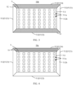
- FIG. 3 is a schematic diagram of a structure of a reflective film 50b according to another embodiment of this application.
- rear sides 512b of inclined parts 512 are partially covered by a coating layer 52.
- a surface of a second inclined part 5122 and a surface of a fourth inclined part 5124 are covered by the coating layer 52.
- the coating layer 52 is provided on surfaces of the inclined parts 512 extending along two long sides of a bottom 511. In this way, stiffness of the reflective film 50b can be ensured.
- the manufacturing process is simplified, and materials are saved.
- the provision of the coating layer 52 on opposite inclined parts 512 of a reflective layer 51 enables mechanical performance of the reflective film 50b to be relatively symmetrical.
- the coating layer 52 may alternatively be provided on one or three inclined parts 512, or the coating layer 52 is provided on each inclined part 512 at intervals. This is not limited herein.
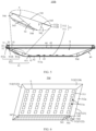
- FIG. 4 is a schematic diagram of a structure of a reflective film 50c according to yet another embodiment of this application.
- no coating layer 52 is provided on inclined parts 512 of a reflective layer 51, but an adhesive tape 53 is adhered on the inclined parts 512.
- the adhesive tape 53 is adhered on a rear side 512b of a fourth inclined part 5124.
- the adhesive tape 53 can improve stiffness of the reflective film 50c and mitigate problems such as bulging and collapsing of the inclined parts 512 of the reflective film 50c.
- the adhesive tape 53 may be fully adhered to surfaces of the inclined parts 512, or the adhesive tape 53 may be partially adhered to the surfaces of the inclined parts 512. This is not limited herein. In a case that the adhesive tape 53 is fully adhered to the surfaces of the inclined parts 512, the process is simple, and time of the manufacturing process is reduced. In a case that a plurality of adhesive tapes 53 are adhered to the surfaces of the inclined parts 512 at intervals, material cost can be reduced.
- the reflective layer of the reflective film may be provided with both the coating layer and the adhesive tape.
- the reflective layer may be fully covered by the coating layer (for example, a front side and/or a rear side of the reflective layer are/is fully covered by the coating layer), and the adhesive tape is adhered to a side that is of the coating layer and that faces away from the reflective layer.
- the adhesive tape is fully adhered to a side that is of the coating layer and that faces away from the reflective layer. In this way, the process is simple, and time of the manufacturing process is reduced.
- a plurality of adhesive tapes are adhered at intervals onto a side that is of the coating layer and that faces away from the reflective layer, to reduce material cost.
- the reflective layer is partially covered by the coating layer
- the adhesive tape is arranged at the same layer as the coating layer, and the adhesive tape is adhered to a position that is on the reflective layer and that is not covered by the coating layer.
- the rear side 512b of the inclined part 512 is partially covered by the coating layer 52, and the adhesive tape 53 may be adhered in a region that is of the rear side 512b of the inclined part 512 and that is not covered by the coating layer 52.
- the rear side 512b of the inclined part 512 is fully covered by the coating layer 52, and the adhesive tape 53 is adhered to a surface that is of the coating layer 52 and that is away from the inclined part 512, or the plurality of adhesive tapes 53 are adhered to the surface that is of the coating layer 52 and that is away from the inclined part 512.
- FIG. 5 is a schematic diagram of a structure of a display apparatus 100b according to another embodiment of this application.
- a difference between the display apparatus 100b in FIG. 5 and the display apparatus 100a in FIG. 1 is that, in the display apparatus 100b, the rear side 512b of the inclined part 512 of the reflective layer 51 is not provided with the coating layer 52 but is provided with support structures 54.
- the support structures 54 abut against bending parts 412a of a back plate 41, to support the reflective layer 51.
- the provision of the support structures 54 can effectively enhance support between a reflective film 50d and the back plate 41, without affecting a normal function of a front side 512a of the reflective film 50d, to effectively mitigate problems such as bulging and collapsing of inclined surfaces of the reflective film 50d.
- each support structure 54 includes a fixed surface 541, a first extending surface 545, a supporting surface 542, a joint surface 544, a transition surface 543, and a second extending surface 546 that are connected sequentially.
- the fixed surface 541 is laminated and fixed onto the rear side 512b of the inclined part 512 of the reflective layer 51.
- the supporting surface 542 connects the fixed surface 541 and the first extending surface 545, and forms a first preset included angle ⁇ with the rear side 512b of the inclined part 512.
- the first preset included angle is close to or equal to 90 degrees
- the bending part 412a of the back plate 41 is approximately parallel with the inclined parts 512 of the reflective layer 51, so that the supporting surface 542 is approximately perpendicular to the bending part 412a of the back plate 41, to support the reflective layer 51.
- the joint surface 544 connects the transition surface 543 and the supporting surface 542, and is adhered to the bending part 412a of the back plate 41.
- the joint surfaces 544 are bonded to the side plates 412 by an adhesive layer, to further enhance stability of the support structures 54 in supporting the reflective layer 51.
- the transition surface 543 connects the second extending surface 546 and the fixed surface 541, and forms a second preset included angle ⁇ with the rear side 512b of the inclined part 512, to be lapped on the rear side 512b of the reflective layer 51 via the second extending surface 546.
- the first extending surface 545 is connected to the supporting surface 542 and extends to cover the rear side 512b of the inclined part 512.
- the second extending surface 546 connects the transition surface 543 and the fixed surface 541, and extends to cover the rear side 512b of the inclined part 512.
- the fixed surface 541, the supporting surface 542, the joint surface 544, and the transition surface 543 come together to form a right trapezoid in a cross section of the support structure 54
- the supporting surface 542 is perpendicular to the fixed surface 541
- the fixed surface 541 is a long side of the trapezoid
- the joint surface 544 is a short side of the right trapezoid.
- the first extending surface 545 and the second extending surface 546 are laminated and fixed onto the reflective layer 51, to effectively transit a connection between the support structure 54 and the reflective layer 51, prevent affecting an effect of the front side 512a of the reflective film 50d, and maintain stability of the support structure 54 in supporting the reflective layer 51.
- the first extending surface 545 is in direct contact with the reflective layer 51, and there are no other film layers between the first extending surface 545 and the reflective layer 51.
- the second extending surface 546 is in direct contact with the reflective layer 51, and there are no other film layers between the second extending surface 546 and the reflective layer 51.
- the first preset included angle ⁇ ranges from 10 degrees to 90 degrees
- the second preset included angle ⁇ ranges from 10 degrees to 90 degrees.
- the first preset included angle ranges from 10 degrees to 20 degrees, 20 degrees to 30 degrees, 30 degrees to 40 degrees, 40 degrees to 50 degrees, 50 degrees to 60 degrees, 60 degrees to 70 degrees, 70 degrees to 80 degrees, or 80 degrees to 90 degrees.
- the second preset included angle ⁇ ranges from 10 degrees to 20 degrees, 20 degrees to 30 degrees, 30 degrees to 40 degrees, 40 degrees to 50 degrees, 50 degrees to 60 degrees, 60 degrees to 70 degrees, 70 degrees to 80 degrees, or 80 degrees to 90 degrees.
- one of the first preset included angle ⁇ and the second preset included angle ⁇ is close to 90 degrees, to support the reflective layer 51.
- the first preset included angle ⁇ is close to or equal to 90 degrees
- the supporting surface 542 is approximately perpendicular to the fixed surface 541.
- a larger second preset included angle ⁇ indicates a smaller area of the transition surface 543 and a larger area of the joint surface 544, so that the bonding between the joint surface 544 and the back plate 41 is more stable, in the direction perpendicular to the rear side 512b, the quadrangle formed by the fixed surface 541, the supporting surface 542, the joint surface 544, and the transition surface 543 coming together in a cross section of the support structure 54 is more like a rectangle, a mechanical strength of the support structure 54 is higher, and the support for the reflective layer 51 is more stable.
- a smaller second preset included angle ⁇ indicates a larger area of the transition surface 543 and a more gentle inclination of the connection between the support structure 54 and the reflective layer 51, thereby effectively preventing a problem of bulging of the reflective layer 51 at the support structure 54 because the side plates 412 provide a support force to the support structure 54 toward the reflective layer 51 at the support structure after the transmit film is lapped 41 on the back plate 41.
- the support structure 54 includes an organic base and a plurality of inorganic particles dispersed in the organic base.
- a material of the organic base is, for example but not limited to, PET.
- the inorganic particles are, for example but not limited to, zirconia, niobium oxide, or silicon oxide.
- the inorganic particles are dispersed in the organic base, so that the stiffness of the support structure 54 is improved, and the inorganic particles can refract or reflect light to facilitate convergence of light toward a side of the liquid crystal display panel 10, thereby improving light utilization.
- a thickness of the organic base ranges from 50 ⁇ m to 300 ⁇ m.
- the thickness of the organic base ranges from 50 ⁇ m to 80 ⁇ m, 80 ⁇ m to 120 ⁇ m, 120 ⁇ m to 150 ⁇ m, 150 ⁇ m to 200 ⁇ m, 200 ⁇ m to 250 ⁇ m, or 250 ⁇ m to 300 ⁇ m.
- the thickness of the organic base may be selected based on a structure of the back plate that matches the reflective film, to at least ensure that after the reflective film obtained by laminating the organic base and the reflective layer is lapped on the back plate, the support structures abut against the back plate, rather than suspending relative to the back plate.
- the thickness of the organic base is approximately uniform, and during laminating the organic base to the reflective layer, a partial region of the organic base becomes thinner after being laminated to the reflective layer, to form a first extending surface and a second extending surface.
- the thickness of the organic base that ranges from 50 ⁇ m to 300 ⁇ m refers to a thickness before the organic base being laminated to the reflective layer.
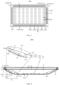
- FIG. 6 is a schematic diagram of a front side 512a of a reflective film 50d in FIG. 5 .
- FIG. 6 only a support structure 54 on the third inclined part 5123 is drawn, the support structures 54 on the other three inclined parts 512 are omitted.
- the first extending surface 545 and the second extending surface 546 of the support structure 54 are omitted.
- the support structure 54 further includes two side surfaces 547 relative to each other.
- the side surfaces 547 connect the fixed surface 541, the supporting surface 542, the joint surface 544 and the transition surface 543
- the side surface 547 is substantially in a shape of a right trapezoid, and the side surfaces 547, the fixed surface 541, the supporting surface 542, the joint surface 544, and the transition surface 543 come together to form a quadrangular prism substantially.
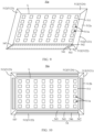
- FIG. 7 is a schematic diagram of a rear side 512b of a reflective film 50d in FIG. 5 .
- a rear side 512b of each inclined part 512 is provided with a support structure 54 to maximally improve a stiffness of the inclined parts 512 of the reflective film 50d and fill gaps G between the reflective layer 51 and the inclined parts 512 of the back plate 41, to effectively mitigate problems such as bulging and collapsing of inclined surfaces of the reflective film 50d.
- FIG. 8 is a schematic diagram of a structure of a display apparatus 100c according to an embodiment of this application.
- the support structure 54 does not include the joint surface in the display apparatus 100c.
- the fixed surface 541, the supporting surface 542, and the transition surface 543 come together to form a triangle in a cross section of the support structure 54.
- a support structure 54 with a triangular cross section provides a stable support and a simple structure. Specifically, the triangle is a right triangle, and can provide better support for the reflective layer 51.
- FIG. 9 is a schematic diagram of a front side 512a of a reflective film 50e in FIG. 8 .
- the support structures 54 on the other three inclined parts 512 are omitted.
- the first extending surface 545 and the second extending surface 546 of the support structure 54 are omitted.
- the support structure 54 further includes two side surfaces 547 relative to each other.
- the side surfaces 547 connect the fixed surface 541, the supporting surface 542 and the transition surface 543.
- the side surface 547 is substantially in a shape of a right triangle, and the side surfaces 547, the fixed surface 541, the supporting surface 542, and the transition surface 543 come together to form a triangular prism substantially.
- FIG. 10 is a schematic diagram of a rear side 512b of a reflective film 50e in FIG. 8 .
- a rear side 512b of each inclined part 512 is provided with a support structure 54 to maximally improve a stiffness of the inclined parts 512 of the reflective film 50e and fill gaps G between the reflective layer 51 and the inclined parts 512 of the back plate 41, to effectively mitigate problems such as bulging and collapsing of inclined surfaces of the reflective film 50e.
- a shape of the support structure is not limited to that shown in FIG. 7 and FIG. 10 .
- the support structure may not include the first extending surface and the second extending surface.
- the support structure may be a pentagonal prism, at least in side surfaces of the pentagonal prism, one side surface is in direct contact with the reflective layer and is fixed, one side surface supports between the reflective layer and the back plate, one side surface is adhered to the back plate, remaining two side surfaces are the transition surfaces.
- distribution of the support structure is not limited to FIG. 7 and FIG. 10 .
- the support structure is disposed corresponding to one inclined part.
- the support structure is disposed corresponding to two inclined parts, and the two inclined parts may be disposed opposite to each other or adjacent to each other, preferably opposite to each other, so that a mechanical strength of the reflective film is approximately uniform.
- the support structure is disposed corresponding to three inclined parts.
- the support structure is not limited to a continuous structure on the inclined parts. For example, a plurality of support structures are provided at a surface of the inclined part at intervals, to provide partial support for the reflective layer; alternatively, the support structures are provided for four corners of the bottom of the reflective layer, to prevent the reflective layer from collapsing or bulging of the four corners.
- any two or three combinations of the coating layer, the adhesive tape, the support structure may be provided at the rear side of the reflective layer, and the rear side of the inclined part may be fully or partially covered by any one of the coating layer, the adhesive tape, and the support structure.
- the support structure is further provided on the coating layer after the rear side of the inclined part is fully or partially provided with the coating layer; alternatively, the support structure is further provided on the adhesive tape after the rear side of the inclined part is fully or partially provided with the adhesive tape; alternatively, the coating layer is provided on a partial region of the inclined part, the partial region is provided with the adhesive tape, the support structure and the like.
- the coating layer is provided on, and/or the adhesive tape is adhered to, and/or the support structure is provided on the reflective layer of the reflective film, this may implement an effective support of the inclined parts of the reflective layer, effectively mitigate the problem of collapsing or bulging of the edges of the reflective film, and improve a display effect of the display apparatus using the reflective film.
- improvement of a partial position of the reflective film can reduce the material cost effectively.
Landscapes
- Physics & Mathematics (AREA)
- Nonlinear Science (AREA)
- Mathematical Physics (AREA)
- Chemical & Material Sciences (AREA)
- Crystallography & Structural Chemistry (AREA)
- General Physics & Mathematics (AREA)
- Optics & Photonics (AREA)
- Planar Illumination Modules (AREA)
- Liquid Crystal (AREA)
Abstract
Description
- This application claims priority to
Chinese Patent Application No. 202111517368.1, filed with the China National Intellectual Property Administration on December 13, 2021 - This application relates to the field of display technologies, and in particular, to a reflective film, a backlight module using the reflective film, and a display apparatus using the backlight module.
- A problem of collapsing or bulging of edges of a reflective film exists in existing direct backlight modules.
- A first aspect of this application provides a reflective film to resolve a problem of collapsing or bulging of edges of a reflective film in existing direct backlight modules. The reflective film includes:
- a reflective layer, where the reflective layer includes a bottom and inclined parts extending around the bottom, folding lines are provided between the inclined parts and the bottom, when the reflective film is folded along the folding lines, the inclined parts are inclined along peripheral edges of the bottom toward a side away from the bottom, the bottom and the inclined parts together form an accommodating space, a plurality of through holes are provided at intervals in the bottom, the inclined parts each include a front side facing the accommodating space and a rear side opposite to the front side, and the front side is configured to reflect light; and
- a coating layer, where the coating layer is provided on the reflective layer to increase stiffness of the reflective film.
- In embodiments of this application, the coating layer is provided on the reflective layer to increase the stiffness of the reflective film (in other words, the stiffness of the reflective film provided with the coating layer is higher than stiffness of the reflective layer itself), so that an effective support is provided for the inclined parts of the reflective layer, thereby effectively mitigating the problem of collapsing or bulging of the edges of the reflective film, and improving a display effect of the display apparatus using the reflective film.
- In some embodiments, a material of the coating layer is a transparent curable adhesive, and the transparent curable adhesive is provided at the rear side and/or the front side. In some other embodiments, the material of the coating layer is a white curable adhesive, the white curable adhesive is provided at the rear side. The white curable adhesive is, for example, a white emulgel. The transparent curable adhesive is, for example, a UV curable adhesive. The stiffness of the reflective film may be increased effectively after the transparent curable adhesive is applied and cured. In addition, because the transparent curable adhesive has a high light transmittance, even if the transparent curable adhesive is provided on the front side of the inclined part of the reflective layer, a normal function of the front sides of the reflective film is not affected. In addition, both the transparent curable adhesive and the white curable adhesive may be provided at the rear side of the inclined part to increase the stiffness of the reflective film, so as to mitigate problems such as the bugling of the reflective film and collapsing of the inclined part. Furthermore, provision of the transparent curable adhesive and the white curable adhesive at the rear side can further ensure that the function of the front side of the reflective film is not reflected. In addition, the coating layer is provided for the inclined parts, but not for a whole surface of the reflective layer, so that material cost of the coating layer can be reduced effectively.
- In some embodiments, a thickness of the coating layer ranges from 50 µm to 200 µm. For example, the thickness of the coating layer ranges from 50 µm to 80 µm, 80 µm to 100 µm, 100 µm to 120 µm, 120 µm to 150 µm, 150 µm to 180 µm, or 180 µm to 200 µm. A thicker coating layer indicates better stiffness of the position on the reflective film corresponding to the coating layer. A thinner coating layer indicates lower material cost of the coating layer.
- In some embodiments, the reflective layer is partially covered by the coating layer. Alternatively, the reflective layer is fully covered by the coating layer. The reflective layer is fully covered by the coating layer, to maximum an area of the coating layer, thereby improving the stiffness of the reflective film. The reflective layer is fully covered by the coating layer. In this way, the stiffness of the reflective film can be ensured. In addition, manufacturing processes are reduced, and materials are saved.
- In some embodiments, the reflective layer is fully covered by the coating layer. The reflective film further includes an adhesive tape, and the adhesive tape is adhered to a side that is of the coating layer and that faces away from the reflective layer. For example, through one operation, the adhesive tape is fully adhered to a side that is of the coating layer and that faces away from the reflective layer. In this way, the process is simple, and time of the manufacturing process is reduced. Alternatively, a plurality of adhesive tapes are adhered at intervals onto a side that is of the coating layer and that faces away from the reflective layer, to reduce material cost. In some other embodiments, the reflective layer is partially covered by the coating layer. The reflective film further includes an adhesive tape, the adhesive tape is arranged at the same layer as the coating layer, and the adhesive tape is adhered to a position that is on the reflective layer and that is not covered by the coating layer.
- In some embodiments, the reflective film further includes support structures, and the support structures each include a fixed surface fixed on the rear side, a supporting surface connected to the fixed surface and forming a first preset included angle with the rear side, and a transition surface connected to the fixed surface and forming a second preset included angle with the rear side. Preferably, the first preset included angle is close to or equal to 90 degrees, and the supporting surface is approximately perpendicular to the fixed surface, to support the reflective layer.
- In some embodiments, in a direction perpendicular to the rear side, the fixed surface, the supporting surface, and the transition surface come together to form a triangle in a cross section of the support structure. A support structure with a triangular cross section provides a stable support and has a simple structure. Specifically, the triangle is a right triangle, which can provide better support for the reflective layer.
- In some embodiments, the support structure further includes a joint surface that connects the transition surface and the supporting surface. The joint surfaces are configured to bond to a back plate (for example, the joint surfaces are bonded to side plates of the back plate by an adhesive layer), to enhance support of the support structures for the reflective layer, and prevent a problem of collapsing of the reflective film during an assembly process.
- In some embodiments, in a direction perpendicular to the rear side, the fixed surface, the supporting surface, the joint surface, and the transition surface come together to form a right trapezoid in a cross section of the support structure, the fixed surface is a long side of the right trapezoid, and the joint surface is a short side of the right trapezoid. The support structure is approximately a quadrangular prism.
- In some embodiments, the support structure further includes a first extending surface connected to the supporting surface and extending to cover the rear side, and a second extending surface connected to the transition surface and extending to cover the rear side. The first extending surface and the second extending surface are laminated and fixed onto the reflective layer, to effectively transit a connection between the support structure and the reflective layer, prevent affecting an effect of the front side of the reflective film, and maintain stability of the support structure in supporting the reflective layer.
- In some embodiments, the first preset included angle ranges from 10 degrees to 90 degrees, and the second preset included angle ranges from 10 degrees to 90 degrees. For example, the first preset included angle ranges from 10 degrees to 20 degrees, 20 degrees to 30 degrees, 30 degrees to 40 degrees, 40 degrees to 50 degrees, 50 degrees to 60 degrees, 60 degrees to 70 degrees, 70 degrees to 80 degrees, or 80 degrees to 90 degrees. The second preset included angle ranges from 10 degrees to 20 degrees, 20 degrees to 30 degrees, 30 degrees to 40 degrees, 40 degrees to 50 degrees, 50 degrees to 60 degrees, 60 degrees to 70 degrees, 70 degrees to 80 degrees, or 80 degrees to 90 degrees. Preferably, one of the first preset included angle and the second preset included angle is close to 90 degrees, to play a main role in supporting the reflective layer.
- In some embodiments, the first preset included angle is close to or equal to 90 degrees, the supporting surface is approximately perpendicular to the fixed surface. A larger second preset included angle indicates a smaller area of the transition surface and a larger area of the joint surface, so that the bonding between the joint surface and the back plate is more stable, in the direction perpendicular to the rear side, the quadrangle formed by the fixed surface, the supporting surface, the joint surface, and the transition surface coming together in a cross section of the support structure is more like a rectangle, a mechanical strength of the support structure is higher, and the support for the reflective layer is more stable. However, when the fixed surface and the supporting surface are constant, a smaller second preset included angle indicates a larger area of the transition surface and a more gentle inclination of the connection between the support structure and the reflective layer, thereby effectively preventing a problem of bulging of the reflective layer at the support structure because the side plates provide a support force to the support structure toward the reflective layer at the support structure after the transmit film is lapped on the back plate. In addition, in configuration of the first preset included angle and the second preset included angle, adjustment of a reflection effect of the reflective layer on light emitted by the light-emitting elements also needs to be considered, to ensure that when the support structures stably support the reflective layer, efficiency of the reflective layer in reflecting light emitted by the light-emitting elements is highest.
- In some embodiments, the support structure includes an organic base and a plurality of inorganic particles dispersed in the organic base. A material of the organic base is, for example but not limited to, PET. The inorganic particles are, for example but not limited to, zirconia, niobium oxide, or silicon oxide. The inorganic particles are dispersed in the organic base, so that the stiffness of the support structure is improved, and the inorganic particles can refract or reflect light to facilitate convergence of light toward a side of the liquid crystal display panel, thereby improving light utilization.
- In some embodiments, a thickness of the organic base ranges from 50 µm to 300 µm. For example, the thickness of the organic base ranges from 50 µm to 80 µm, 80 µm to 120 µm, 120 µm to 150 µm, 150 µm to 200 µm, 200 µm to 250 µm, or 250 µm to 300 µm. Specifically, the thickness of the organic base may be selected based on a structure of the back plate that matches the reflective film, to at least ensure that after the reflective film obtained by laminating the organic base and the reflective layer is lapped on the back plate, the support structures abut against the back plate, rather than suspending relative to the back plate. In addition, before laminated to the reflective layer, the thickness of the organic base is approximately uniform, and during laminating the organic base to the reflective layer, a partial region of the organic base becomes thinner after being laminated to the reflective layer, to form a first extending surface and a second extending surface. The thickness of the organic base that ranges from 50 µm to 300 µm refers to a thickness before the organic base being laminated to the reflective layer.
- A second aspect of this application provides a backlight module, including:
- a back plate, where the back plate includes a bottom plate and side plates that surround the bottom plate and extend inclinedly along peripheral edges of the bottom plate toward a side away from the bottom plate;
- a plurality of light-emitting elements, located on the bottom plate; and
- the reflective film according to the first aspect of this application, where inclined parts are lapped on the side plates, positions of bottoms of the inclined parts correspond to the bottom plate, and each of the light-emitting elements is exposed out of one of through holes and is located in an accommodating space of the reflective film.
- The backlight module is a direct-lit module. Because the backlight module includes the reflective film according to the first aspect of this application, backlight emitted is even.
- In some embodiments, when the reflective film includes support structures, the support structures abut against the side plates, to support the reflective layer. In peripheral gaps, provision of the support structures can enhance support between the reflective film and the back plate without affecting a normal function of the front side of the reflective film, to effectively mitigate problems such as bulging and collapsing of inclined surfaces of the reflective film.
- In some embodiments, when the support structures include joint surfaces, the joint surfaces are bonded to the side plates by an adhesive layer, to further enhance stability of the support structures in supporting the reflective layer.
- A third aspect of this application provides a display apparatus, including:
- a liquid crystal display panel; and
- the backlight module according to the second aspect of this application, where the backlight module is located at a side that is of the liquid crystal display panel and that faces away from a display surface of the liquid crystal display panel.
- Because the backlight module according to the second aspect emits even backlight, the display apparatus does not have a problem of bright or dark spots caused by collapsing or bulging of the reflective film, and therefore has a good display effect.
-
-
FIG. 1 is a schematic diagram of a structure of a display apparatus according to an embodiment of this application; -
FIG. 2 is a schematic diagram of a structure of a reflective film inFIG. 1 ; -
FIG. 3 is a schematic diagram of a structure of a reflective film according to another embodiment of this application; -
FIG. 4 is a schematic diagram of a structure of a reflective film according to yet another embodiment of this application; -
FIG. 5 is a schematic diagram of a structure of a display apparatus according to another embodiment of this application; -
FIG. 6 is a schematic diagram of a front side of a reflective film inFIG. 5 ; -
FIG. 7 is a schematic diagram of a rear side of the reflective film inFIG. 5 ; -
FIG. 8 is a schematic diagram of a structure of a display apparatus according to yet another embodiment of this application; -
FIG. 9 is a schematic diagram of a front side of a reflective film inFIG. 8 ; -
FIG. 10 is a schematic diagram of a rear side of the reflective film inFIG. 8 ; - This application is further described in the following specific embodiments with reference to the accompanying drawings.
-
FIG. 1 is a schematic diagram of a structure of adisplay apparatus 100a according to an embodiment of this application. Thedisplay apparatus 100a may be, for example, a display, a tablet computer, or a television. As shown inFIG. 1 , thedisplay apparatus 100a includes a liquidcrystal display panel 10, abuffer layer 20, amiddle frame 30, and abacklight module 40. - The liquid
crystal display panel 10 is configured to display an image. Thebacklight module 40 is located at a side that is of the liquidcrystal display panel 10 and that faces away from the display side, and thebacklight module 40 is a direct backlight module and is configured to provide backlight for the liquidcrystal display panel 10. Themiddle frame 30 is configured to bear the liquidcrystal display panel 10, and is connected to thebacklight module 40. Specifically, themiddle frame 30 includes a bearingsurface 31, and the liquidcrystal display panel 10 is attached on the bearingsurface 31. Thebuffer layer 20 is provided on the bearingsurface 31, and is located between the liquidcrystal display panel 10 and themiddle frame 30. Thebuffer layer 20 is approximately ring-shaped, and thebuffer layer 20 may be adhered to themiddle frame 30 and the liquidcrystal display panel 10 by using a double-sided adhesive tape (not shown). A material of thebuffer layer 20 is, for example, black foam. The black foam can absorb light, to prevent leakage of light of thebacklight module 40 from a joint between the liquidcrystal display panel 10 and themiddle frame 30, and mitigate a light leakage problem. In addition, the black foam has a buffering function, to prevent breakage and failure of an array substrate of the liquidcrystal display panel 10 caused by squeezing or impact on the liquidcrystal display panel 10 during transportation. - The
backlight module 40 includes aback plate 41, acircuit board 42 located on theback plate 41, a plurality of light-emittingelements 43 located on thecircuit board 42 and electrically connected to thecircuit board 42, areflective film 50a located on a side that is of theback plate 41 and that is close to the liquidcrystal display panel 10, adiffuser plate 44 located a side that is of thereflective film 50a and that is close to the liquidcrystal display panel 10, and anoptical film assembly 45 stacked on thediffuser plate 44 and located on a side that is of thediffuser plate 44 and that is close to the liquidcrystal display panel 10. Theback plate 41 is made of, for example, metal, and has a good mechanical strength. Themain circuit board 42 is, for example, a rigid circuit board, a flexible circuit board, or a rigid-flex circuit board. The light-emittingelement 43 is configured to emit a light beam, and the light-emittingelement 43 is, for example, a light emitting diode (Light Emitting Diode, LED) lamp bead. Thereflective film 50a is lapped on theback plate 41, and is configured to reflect light from the light-emittingelement 43 toward the liquidcrystal display panel 10, to improve light utilization. Thediffuser plate 44 is configured to evenly diffuse light incident onto thediffuser plate 44. Theoptical film assembly 45 include, for example but not limited to, a brightness enhancement film and a light guide plate that are sequentially stacked along a direction moving away from the liquidcrystal display panel 10. - The
back plate 41 includes abottom plate 411 andside plates 412 surrounding thebottom plate 411 and extending incliningly along edges of thebottom plate 411 toward a side away from thebottom plate 411. Theside plate 412 includes abending part 412a, abearing part 412b and a snap-fit part 412c that sequentially extending from thebottom plate 411. Themiddle frame 30 is provided with aslot 32, the snap-fit part 412c matches theslot 32, and the snap-fit part 412c is snapped into theslot 32, so that themiddle frame 30 is snapped onto theback plate 41. In another embodiment, a connection between themiddle frame 30 and theside plates 412 may be, but is not limited to, a threaded connection. Thebearing part 412b is configured to bear thereflective film 50a, thediffuser plate 44, theoptical film assembly 45, and the like. - The
bottom plate 411 of theback plate 41 and theside plates 412 of theback plate 41 come together to form space with a substantially trapezoidal cross section. Thecircuit board 42, the light-emittingelements 43, and thereflective film 50a are located in the trapezoidal space. Thecircuit board 42 is located on thebottom plate 411. - The
reflective film 50a includes areflective layer 51 and acoating layer 52. A material of thereflective layer 51 is, for example but not limited to, polyethylene glycol terephthalate (polyethylene glycol terephthalate, PET). - The
reflective layer 51 includes a bottom 511 andinclined parts 512 extending around thebottom 511. The bottom 511 is flat, folding lines L (as shown inFIG. 2 ) are provided between the bottom 511 and theinclined parts 512 of thereflective film 50a, and the folding lines are, for example, roulettes. Theinclined parts 512 are inclined along edges of the bottom 511 toward a side away from the bottom 511 when thereflective film 50a is folded along the folding lines L, and the bottom 511 and theinclined parts 512 together form an accommodating space S. Thebottom 511 of thereflective film 50a is disposed at a position corresponding to thebottom plate 411 of theback plate 41. A plurality of throughholes 511a are provided at intervals in thebottom 511 of thereflective film 50a. Shapes and dimensions of the plurality of throughholes 511a are matched with those of the plurality of light-emittingelements 43. Each light-emittingelement 43 is exposed out of one throughhole 511a and located in the accommodating space S. Theinclined parts 512 of thereflective film 50a are attached on theside plates 412 of theback plate 41, and theinclined parts 512 of thereflective layer 51 each forms a gap G with the bendingpart 412a of theback plate 41. Specifically, theinclined parts 512 of thereflective film 50a and thebearing part 412b of theback plate 41 may be bonded to each other by, but is not limited to, an adhesive. - It should be noted that, in related technologies, when the reflective film is mounted on a direct-lit back plate, because the side plates of the back plate are designed to be inclined, after the reflective film is lapped on the bearing part of the back plate, a suspending region is formed between the reflective film and the back plate. Because the reflective film is hard to maintain an original plane shape due to its soft material, when the reflective film is mounted onto the back plate in a production line, bulges are very likely to appear on edges during assembly, leading to bright or dark spots on the edges of the display apparatus. As a result, a display effect is affected. In addition, due to the stiffness of the reflective film, a large-size display apparatus has a large suspending region. This may cause a problem of collapsing of the edges in scenarios such as abnormal transportation and vibration, which seriously affects the display effect. However, in an embodiment of this application, in the direct backlight module, to mitigate a problem of collapsing or bugling of the edges of the reflective film when the reflective film is mounted to the back plate or in a scenario such as abnormal transportation and vibration, a reflective film with an edge-reinforced design is provided.
- Specifically, the
inclined parts 512 of thereflective film 50a includefront sides 512a close to the liquid crystal display panel 10 (or in other words, facing the accommodating space S) and configured to reflect light, andrear sides 512b opposite to thefront sides 512a. Thecoating layer 52 is provided at therear side 512b of thereflective layer 51. - A material of the
coating layer 52 is a transparent curable adhesive or a white curable adhesive. After the adhesive is applied and cured, the stiffness of thereflective film 50a can be increased effectively, without affecting a normal function of thefront side 512a of thereflective film 50a. Therefore, problems such as bulging of thereflective film 50a and collapsing of theinclined parts 512 can be mitigated effectively. When thecoating layer 52 is the transparent curable adhesive, thecoating layer 52 is not limited to be provided at therear side 512b of theinclined part 512, and can also be provided at thefront side 512a of theinclined part 512. In this way, the transparent curable adhesive can effectively increase the stiffness of the reflective film, and because the transparent curable adhesive has a good light transmittance, even if being provided on the front side of the inclined part of the reflective layer, the transparent curable adhesive does not affect a normal function of the front side of the reflective film. In addition, thecoating layer 52 is provided for theinclined parts 512, but not for a whole surface of thereflective layer 51. Therefore, material cost of thecoating layer 52 can be reduced effectively. In another embodiment, thecoating layer 52 is, but not limited to, provided at the inclined parts. For example, when thecoating layer 52 is the transparent curable adhesive, thecoating layer 52 may further be provided at a front side that is of the bottom and that is configured to reflect the light and/or a rear side that is of the bottom and that is opposite to the front side. When thecoating layer 52 is the white curable adhesive, thecoating layer 52 may alternatively be provided at the rear side of the bottom. When thecoating layer 52 is provided at surfaces that are of the bottom and the inclined part and that are at the same side (for example, thecoating layer 52 is provided at the front side of the bottom and the front side of the inclined part, or the coating layer is provided at the rear side of the bottom and the rear side of the inclined part), thecoating layer 52 on the inclined part and on the bottom can be formed through one manufacturing process, to simplify the manufacturing process. In addition, the stiffness of the whole reflective film can be enhanced by forming the coating layer at the bottom and the inclined parts. - Specifically, the transparent curable adhesive is, for example, a UV curable acrylate adhesive or transparent room-temperature-curing epoxy resin adhesive. The UV curable acrylate adhesive can quickly (within seconds) be transitioned from liquid to solid after irradiation with UV light. A curing rate of the adhesive is fast, so that time of a manufacturing process is reduced, and production efficiency is improved. In addition, the cured UV curable acrylate adhesive has a high light transmittance (greater than or equal to 90%), and allows most of light to be incident to the reflective layer through the cured UV curable acrylate adhesive and then be reflected by the reflective layer, thereby improving light source utilization of the reflective film. Further, the UV curable acrylate adhesive further has advantages such as yellowing prevention and moisture resistance. This facilitates ensuring reliability of the reflective film in use. The transparent room-temperature-curing epoxy resin adhesive has a good mechanical property and a low curing shrinkage rate. This facilitates ensuring stiffness and flatness of the reflective film. In addition, the transparent room-temperature-curing epoxy resin adhesive further has a good resistance to chemicals. This facilitates ensuring the reliability of the reflective film in use. Furthermore, the transparent room-temperature-curing epoxy resin adhesive is curable in a room temperature, so that a preparation process of the reflective film is simplified.
- The white curable adhesive is, for example but not limited to, a polyvinyl acetate adhesive. The polyvinyl acetate adhesive is a thermoplastic adhesive obtained by polymerization of vinyl acetate monomer. According to different manners of polymerization, polyvinyl acetate adhesives are classified into a solution type and an emulsion type, and generally the emulsion type is more widely used. A vinyl acetate emulsion is commonly known as white emulgel or white glue, and has advantages such as pollution-free, low cost, high adhesion, fast curing speed, simple production process, and usage convenience. Therefore, when the vinyl acetate emulsion is applied on the reflective layer, the reflective film may have corresponding advantages such as environmental protection, low cost, high stiffness, and high production efficiency.
-
FIG. 2 is a schematic diagram of a structure of areflective film 50a inFIG. 1 . As shown inFIG. 2 , thebottom 511 of thereflective layer 51 is substantially rectangular. Each throughhole 511a in the bottom 511 is substantially rectangular, and a plurality of throughholes 511a are arranged in multiple rows and multiple columns. Theinclined parts 512 include four inclined sections extending separately from four edges of the bottom 511 and connected sequentially, that is, a firstinclined part 5121, a secondinclined part 5122, a thirdinclined part 5123, and a fourthinclined part 5124. The firstinclined part 5121 and the thirdinclined part 5123 are opposite to each other and extend from two short sides of the rectangle. The secondinclined part 5122 and the fourthinclined part 5124 are opposite to each other and extend from two long sides of the rectangle. The firstinclined part 5121, the secondinclined part 5122, the thirdinclined part 5123 and the fourthinclined part 5124 are each substantially in a shape of an isosceles trapezoid. - The
rear side 512b of theinclined part 512 is fully covered by thecoating layer 52, to maximum an area of thecoating layer 52 and improve the stiffness of thereflective film 50a. - In another embodiment, a shape of the bottom 511, shapes of the
inclined parts 512, and shapes and arrangements of the throughholes 511a are not limited to those mentioned. For example, the bottom 511 may be in a shape of a parallelogram, an ellipse, or the like. The firstinclined part 5121, the secondinclined part 5122, the thirdinclined part 5123, or the fourthinclined part 5124 may be formed by jointing a plurality of parts, rather than an integrally formed trapezoid. The throughholes 511a may be circular holes, elliptical holes, or the like. - A thickness of the
coating layer 52 ranges from 50 µm to 200 µm. For example, the thickness of thecoating layer 52 ranges from 50 µm to 80 µm, 80 µm to 100 µm, 100 µm to 120 µm, 120 µm to 150 µm, 150 µm to 180 µm, and 180 µm to 200 µm. Athicker coating layer 52 indicates higher stiffness of the position on thereflective film 50a corresponding to thecoating layer 52. Athinner coating layer 52 indicates lower material cost of thecoating layer 52. -
FIG. 3 is a schematic diagram of a structure of areflective film 50b according to another embodiment of this application. As shown inFIG. 3 ,rear sides 512b ofinclined parts 512 are partially covered by acoating layer 52. A surface of a secondinclined part 5122 and a surface of a fourthinclined part 5124 are covered by thecoating layer 52. Thecoating layer 52 is provided on surfaces of theinclined parts 512 extending along two long sides of a bottom 511. In this way, stiffness of thereflective film 50b can be ensured. In addition, the manufacturing process is simplified, and materials are saved. In addition, the provision of thecoating layer 52 on oppositeinclined parts 512 of areflective layer 51 enables mechanical performance of thereflective film 50b to be relatively symmetrical. In another embodiment, thecoating layer 52 may alternatively be provided on one or threeinclined parts 512, or thecoating layer 52 is provided on eachinclined part 512 at intervals. This is not limited herein. -
FIG. 4 is a schematic diagram of a structure of areflective film 50c according to yet another embodiment of this application. As shown inFIG. 4 , nocoating layer 52 is provided oninclined parts 512 of areflective layer 51, but anadhesive tape 53 is adhered on theinclined parts 512. Theadhesive tape 53 is adhered on arear side 512b of a fourthinclined part 5124. Theadhesive tape 53 can improve stiffness of thereflective film 50c and mitigate problems such as bulging and collapsing of theinclined parts 512 of thereflective film 50c. - In another embodiment, the
adhesive tape 53 may be fully adhered to surfaces of theinclined parts 512, or theadhesive tape 53 may be partially adhered to the surfaces of theinclined parts 512. This is not limited herein. In a case that theadhesive tape 53 is fully adhered to the surfaces of theinclined parts 512, the process is simple, and time of the manufacturing process is reduced. In a case that a plurality ofadhesive tapes 53 are adhered to the surfaces of theinclined parts 512 at intervals, material cost can be reduced. - In some embodiments, the reflective layer of the reflective film may be provided with both the coating layer and the adhesive tape. For example, the reflective layer may be fully covered by the coating layer (for example, a front side and/or a rear side of the reflective layer are/is fully covered by the coating layer), and the adhesive tape is adhered to a side that is of the coating layer and that faces away from the reflective layer. Through one operation, the adhesive tape is fully adhered to a side that is of the coating layer and that faces away from the reflective layer. In this way, the process is simple, and time of the manufacturing process is reduced. Alternatively, a plurality of adhesive tapes are adhered at intervals onto a side that is of the coating layer and that faces away from the reflective layer, to reduce material cost. For another example, the reflective layer is partially covered by the coating layer, the adhesive tape is arranged at the same layer as the coating layer, and the adhesive tape is adhered to a position that is on the reflective layer and that is not covered by the coating layer. Specifically, the
rear side 512b of theinclined part 512 is partially covered by thecoating layer 52, and theadhesive tape 53 may be adhered in a region that is of therear side 512b of theinclined part 512 and that is not covered by thecoating layer 52. Alternatively, therear side 512b of theinclined part 512 is fully covered by thecoating layer 52, and theadhesive tape 53 is adhered to a surface that is of thecoating layer 52 and that is away from theinclined part 512, or the plurality ofadhesive tapes 53 are adhered to the surface that is of thecoating layer 52 and that is away from theinclined part 512. -
FIG. 5 is a schematic diagram of a structure of adisplay apparatus 100b according to another embodiment of this application. A difference between thedisplay apparatus 100b inFIG. 5 and thedisplay apparatus 100a inFIG. 1 is that, in thedisplay apparatus 100b, therear side 512b of theinclined part 512 of thereflective layer 51 is not provided with thecoating layer 52 but is provided withsupport structures 54. - As shown in
FIG. 5 , thesupport structures 54 abut against bendingparts 412a of aback plate 41, to support thereflective layer 51. In peripheral gaps, the provision of thesupport structures 54 can effectively enhance support between areflective film 50d and theback plate 41, without affecting a normal function of afront side 512a of thereflective film 50d, to effectively mitigate problems such as bulging and collapsing of inclined surfaces of thereflective film 50d. - Specifically, each
support structure 54 includes a fixedsurface 541, a first extendingsurface 545, a supportingsurface 542, ajoint surface 544, atransition surface 543, and a second extendingsurface 546 that are connected sequentially. The fixedsurface 541 is laminated and fixed onto therear side 512b of theinclined part 512 of thereflective layer 51. The supportingsurface 542 connects the fixedsurface 541 and the first extendingsurface 545, and forms a first preset included angle β with therear side 512b of theinclined part 512. Preferably, the first preset included angle is close to or equal to 90 degrees, the bendingpart 412a of theback plate 41 is approximately parallel with theinclined parts 512 of thereflective layer 51, so that the supportingsurface 542 is approximately perpendicular to thebending part 412a of theback plate 41, to support thereflective layer 51. Thejoint surface 544 connects thetransition surface 543 and the supportingsurface 542, and is adhered to thebending part 412a of theback plate 41. For example, thejoint surfaces 544 are bonded to theside plates 412 by an adhesive layer, to further enhance stability of thesupport structures 54 in supporting thereflective layer 51. Thetransition surface 543 connects the second extendingsurface 546 and the fixedsurface 541, and forms a second preset included angle α with therear side 512b of theinclined part 512, to be lapped on therear side 512b of thereflective layer 51 via the second extendingsurface 546. The first extendingsurface 545 is connected to the supportingsurface 542 and extends to cover therear side 512b of theinclined part 512. The second extendingsurface 546 connects thetransition surface 543 and the fixedsurface 541, and extends to cover therear side 512b of theinclined part 512. In a direction perpendicular to therear side 512b, the fixedsurface 541, the supportingsurface 542, thejoint surface 544, and thetransition surface 543 come together to form a right trapezoid in a cross section of thesupport structure 54, the supportingsurface 542 is perpendicular to the fixedsurface 541, the fixedsurface 541 is a long side of the trapezoid, and thejoint surface 544 is a short side of the right trapezoid. - In some embodiments, the first extending
surface 545 and the second extendingsurface 546 are laminated and fixed onto thereflective layer 51, to effectively transit a connection between thesupport structure 54 and thereflective layer 51, prevent affecting an effect of thefront side 512a of thereflective film 50d, and maintain stability of thesupport structure 54 in supporting thereflective layer 51. Specifically, the first extendingsurface 545 is in direct contact with thereflective layer 51, and there are no other film layers between the first extendingsurface 545 and thereflective layer 51. The second extendingsurface 546 is in direct contact with thereflective layer 51, and there are no other film layers between the second extendingsurface 546 and thereflective layer 51. - In some embodiments, the first preset included angle β ranges from 10 degrees to 90 degrees, and the second preset included angle α ranges from 10 degrees to 90 degrees. For example, the first preset included angle ranges from 10 degrees to 20 degrees, 20 degrees to 30 degrees, 30 degrees to 40 degrees, 40 degrees to 50 degrees, 50 degrees to 60 degrees, 60 degrees to 70 degrees, 70 degrees to 80 degrees, or 80 degrees to 90 degrees. The second preset included angle α ranges from 10 degrees to 20 degrees, 20 degrees to 30 degrees, 30 degrees to 40 degrees, 40 degrees to 50 degrees, 50 degrees to 60 degrees, 60 degrees to 70 degrees, 70 degrees to 80 degrees, or 80 degrees to 90 degrees. Preferably, one of the first preset included angle β and the second preset included angle α is close to 90 degrees, to support the
reflective layer 51. - In some embodiments, the first preset included angle β is close to or equal to 90 degrees, the supporting
surface 542 is approximately perpendicular to the fixedsurface 541. A larger second preset included angle α indicates a smaller area of thetransition surface 543 and a larger area of thejoint surface 544, so that the bonding between thejoint surface 544 and theback plate 41 is more stable, in the direction perpendicular to therear side 512b, the quadrangle formed by the fixedsurface 541, the supportingsurface 542, thejoint surface 544, and thetransition surface 543 coming together in a cross section of thesupport structure 54 is more like a rectangle, a mechanical strength of thesupport structure 54 is higher, and the support for thereflective layer 51 is more stable. However, a smaller second preset included angle α indicates a larger area of thetransition surface 543 and a more gentle inclination of the connection between thesupport structure 54 and thereflective layer 51, thereby effectively preventing a problem of bulging of thereflective layer 51 at thesupport structure 54 because theside plates 412 provide a support force to thesupport structure 54 toward thereflective layer 51 at the support structure after the transmit film is lapped 41 on theback plate 41. In addition, in configuration of the first preset included angle β and the second preset included angle α, adjustment of a reflection effect of thereflective layer 51 on light emitted by the light-emittingelements 43 also needs to be considered, to ensure that when thesupport structures 54 stably support thereflective layer 51, efficiency of thereflective layer 51 in reflecting light emitted by the light-emittingelements 43 is maximum. - In some embodiments, the
support structure 54 includes an organic base and a plurality of inorganic particles dispersed in the organic base. A material of the organic base is, for example but not limited to, PET. The inorganic particles are, for example but not limited to, zirconia, niobium oxide, or silicon oxide. The inorganic particles are dispersed in the organic base, so that the stiffness of thesupport structure 54 is improved, and the inorganic particles can refract or reflect light to facilitate convergence of light toward a side of the liquidcrystal display panel 10, thereby improving light utilization. - In some embodiments, a thickness of the organic base ranges from 50 µm to 300 µm. For example, the thickness of the organic base ranges from 50 µm to 80 µm, 80 µm to 120 µm, 120 µm to 150 µm, 150 µm to 200 µm, 200 µm to 250 µm, or 250 µm to 300 µm. Specifically, the thickness of the organic base may be selected based on a structure of the back plate that matches the reflective film, to at least ensure that after the reflective film obtained by laminating the organic base and the reflective layer is lapped on the back plate, the support structures abut against the back plate, rather than suspending relative to the back plate. In addition, before laminated to the reflective layer, the thickness of the organic base is approximately uniform, and during laminating the organic base to the reflective layer, a partial region of the organic base becomes thinner after being laminated to the reflective layer, to form a first extending surface and a second extending surface. The thickness of the organic base that ranges from 50 µm to 300 µm refers to a thickness before the organic base being laminated to the reflective layer.
-
FIG. 6 is a schematic diagram of afront side 512a of areflective film 50d inFIG. 5 . For clear description, inFIG. 6 , only asupport structure 54 on the thirdinclined part 5123 is drawn, thesupport structures 54 on the other threeinclined parts 512 are omitted. In addition, inFIG. 6 , the first extendingsurface 545 and the second extendingsurface 546 of thesupport structure 54 are omitted. As shown inFIG. 6 , thesupport structure 54 further includes twoside surfaces 547 relative to each other. The side surfaces 547 connect the fixedsurface 541, the supportingsurface 542, thejoint surface 544 and thetransition surface 543 Theside surface 547 is substantially in a shape of a right trapezoid, and the side surfaces 547, the fixedsurface 541, the supportingsurface 542, thejoint surface 544, and thetransition surface 543 come together to form a quadrangular prism substantially. -
FIG. 7 is a schematic diagram of arear side 512b of areflective film 50d inFIG. 5 . As shown inFIG. 7 , arear side 512b of eachinclined part 512 is provided with asupport structure 54 to maximally improve a stiffness of theinclined parts 512 of thereflective film 50d and fill gaps G between thereflective layer 51 and theinclined parts 512 of theback plate 41, to effectively mitigate problems such as bulging and collapsing of inclined surfaces of thereflective film 50d. -
FIG. 8 is a schematic diagram of a structure of adisplay apparatus 100c according to an embodiment of this application. A difference between thedisplay apparatus 100c shown inFIG 8 and thedisplay apparatus 100b shown inFIG. 5 is that thesupport structure 54 does not include the joint surface in thedisplay apparatus 100c. In a direction perpendicular to therear side 512b, the fixedsurface 541, the supportingsurface 542, and thetransition surface 543 come together to form a triangle in a cross section of thesupport structure 54. Asupport structure 54 with a triangular cross section provides a stable support and a simple structure. Specifically, the triangle is a right triangle, and can provide better support for thereflective layer 51. -
FIG. 9 is a schematic diagram of afront side 512a of areflective film 50e inFIG. 8 . Similarly, for clear description, inFIG. 9 , only asupport structure 54 on the thirdinclined part 5123 is drawn, thesupport structures 54 on the other threeinclined parts 512 are omitted. In addition, inFIG. 9 , the first extendingsurface 545 and the second extendingsurface 546 of thesupport structure 54 are omitted. As shown inFIG. 9 , thesupport structure 54 further includes twoside surfaces 547 relative to each other. The side surfaces 547 connect the fixedsurface 541, the supportingsurface 542 and thetransition surface 543. Theside surface 547 is substantially in a shape of a right triangle, and the side surfaces 547, the fixedsurface 541, the supportingsurface 542, and thetransition surface 543 come together to form a triangular prism substantially. -
FIG. 10 is a schematic diagram of arear side 512b of areflective film 50e inFIG. 8 . As shown inFIG. 10 , arear side 512b of eachinclined part 512 is provided with asupport structure 54 to maximally improve a stiffness of theinclined parts 512 of thereflective film 50e and fill gaps G between thereflective layer 51 and theinclined parts 512 of theback plate 41, to effectively mitigate problems such as bulging and collapsing of inclined surfaces of thereflective film 50e. - In another embodiment, a shape of the support structure is not limited to that shown in
FIG. 7 andFIG. 10 . For example, the support structure may not include the first extending surface and the second extending surface. Alternatively, the support structure may be a pentagonal prism, at least in side surfaces of the pentagonal prism, one side surface is in direct contact with the reflective layer and is fixed, one side surface supports between the reflective layer and the back plate, one side surface is adhered to the back plate, remaining two side surfaces are the transition surfaces. In addition, distribution of the support structure is not limited toFIG. 7 andFIG. 10 . For example, the support structure is disposed corresponding to one inclined part. Alternatively, the support structure is disposed corresponding to two inclined parts, and the two inclined parts may be disposed opposite to each other or adjacent to each other, preferably opposite to each other, so that a mechanical strength of the reflective film is approximately uniform. Alternatively, the support structure is disposed corresponding to three inclined parts. In addition, the support structure is not limited to a continuous structure on the inclined parts. For example, a plurality of support structures are provided at a surface of the inclined part at intervals, to provide partial support for the reflective layer; alternatively, the support structures are provided for four corners of the bottom of the reflective layer, to prevent the reflective layer from collapsing or bulging of the four corners. - It should be noted that the reflective film used in the foregoing embodiments may be properly deformed without departing from the spirit and scope of technical solutions of this application. In another words, any two or three combinations of the coating layer, the adhesive tape, the support structure may be provided at the rear side of the reflective layer, and the rear side of the inclined part may be fully or partially covered by any one of the coating layer, the adhesive tape, and the support structure. For example, the support structure is further provided on the coating layer after the rear side of the inclined part is fully or partially provided with the coating layer; alternatively, the support structure is further provided on the adhesive tape after the rear side of the inclined part is fully or partially provided with the adhesive tape; alternatively, the coating layer is provided on a partial region of the inclined part, the partial region is provided with the adhesive tape, the support structure and the like.
- In embodiments of this application, the coating layer is provided on, and/or the adhesive tape is adhered to, and/or the support structure is provided on the reflective layer of the reflective film, this may implement an effective support of the inclined parts of the reflective layer, effectively mitigate the problem of collapsing or bulging of the edges of the reflective film, and improve a display effect of the display apparatus using the reflective film. In addition, compared with a design of a full reflective film, in embodiments of this application, improvement of a partial position of the reflective film can reduce the material cost effectively.
- The foregoing implementations are merely intended for describing the technical solutions of this application but not for limiting this application. Although this application is described in detail with reference to the exemplary implementations, a person of ordinary skill in the art should understand that modifications or equivalent replacements may be made to the technical solutions of this application without departing from the spirit and scope of this application.
| |
100a, 100b, 100c |
| Liquid |
10 |
| |
20 |
| |
30 |
| |
31 |
| |
32 |
| |
40 |
| |
41 |
| |
411 |
| |
412 |
| |
|
| Bearing part | |
| 412b | |
| Snap- |
|
| Circuit board | |
| 42 | |
| Light-emitting |
43 |
| |
44 |
| |
45 |
| |
50a, 50b, 50c, 50d, 50e |
| Accommodating space | S |
| |
51 |
| |
511 |
| Through |
511a |
| |
512 |
| |
512a |
| |
512b |
| First |
5121 |
| Second inclined |
5122 |
| Third inclined |
5123 |
| Fourth inclined |
5124 |
| |
52 |
| |
53 |
| |
54 |
| |
541 |
| |
542 |
| |
543 |
| First preset included angle | β |
| Second preset included angle | α |
| |
544 |
| |
545 |
| |
546 |
| |
547 |
| Gap | G |
| Folding line | L |
Claims (39)
- A reflective film, comprising:a reflective layer, wherein the reflective layer comprises a bottom and inclined parts extending around the bottom, folding lines are provided between the inclined parts and the bottom, when the reflective film is folded along the folding lines, the inclined parts are inclined along peripheral edges of the bottom toward a side away from the bottom, the bottom and the inclined parts together form an accommodating space, a plurality of through holes are provided at intervals in the bottom, the inclined parts each comprise a front side facing the accommodating space and a rear side opposite to the front side, and the front side is configured to reflect light; anda coating layer, wherein the coating layer is provided on the reflective layer to increase stiffness of the reflective film.
- The reflective film according to claim 1, wherein a material of the coating layer is a transparent curable adhesive, and the transparent curable adhesive is provided at the rear side and/or the front side.
- The reflective film according to claim 1, wherein a material of the coating layer is a white curable adhesive, the white curable adhesive is provided at the rear side.
- The reflective film according to claim 1, wherein a thickness of the coating layer ranges from 50 µm to 200 µm.
- The reflective film according to any one of claims 1 to 4, wherein the reflective layer is fully covered by the coating layer.
- The reflective film according to claim 5, wherein the reflective film further comprises an adhesive tape, and the adhesive tape is adhered to a side that is of the coating layer and that faces away from the reflective layer.
- The reflective film according to any one of claims 1 to 4, wherein the reflective layer is partially covered by the coating layer.
- The reflective film according to claim 7, wherein the reflective film further comprises an adhesive tape, the adhesive tape is arranged at the same layer as the coating layer, and the adhesive tape is adhered to a position that is on the reflective layer and that is not covered by the coating layer.
- The reflective film according to claim 1, wherein the reflective film further comprises support structures, the support structures each comprise a fixed surface fixed on the rear side, a supporting surface connected to the fixed surface and forming a first preset included angle with the rear side, and a transition surface connected to the fixed surface and forming a second preset included angle with the rear side.
- The reflective film according to claim 9, wherein in a direction perpendicular to the rear side, the fixed surface, the supporting surface, and the transition surface come together to form a right triangle in a cross section of the support structure.
- The reflective film according to claim 9, wherein the support structure further comprises a j oint surface that connects the transition surface and the supporting surface.
- The reflective film according to claim 11, wherein in a direction perpendicular to the rear side, the fixed surface, the supporting surface, the joint surface, and the transition surface come together to form a right trapezoid in a cross section of the support structure, the fixed surface is a long side of the right trapezoid, and the joint surface is a short side of the right trapezoid.
- The reflective film according to any one of claims 9 to 12, wherein the support structure further comprises a first extending surface connected to the supporting surface and extending to cover the rear side, and a second extending surface connected to the transition surface and extending to cover the rear side.
- The reflective film according to claim 13, wherein the first extending surface and the second extending surface are laminated and fixed onto the reflective layer.
- The reflective film according to claim 9, wherein the first preset included angle ranges from 10 degrees to 90 degrees, and the second preset included angle ranges from 10 degrees to 90 degrees.
- The reflective film according to claim 9, wherein the support structure comprises an organic base and a plurality of inorganic particles dispersed in the organic base.
- The reflective film according to claim 16, wherein a thickness of the organic base ranges from 50 µm to 300 µm.
- A backlight module, comprising:a back plate, wherein the back plate comprises a bottom plate and side plates surrounding the bottom plate and extending inclinedly along peripheral edges of the bottom plate toward a side away from the bottom plate;a plurality of light-emitting elements, located on the bottom plate; andthe reflective film according to any one of claims 1 to 17, wherein the inclined parts are lapped on the side plates, a position of the bottom corresponds to the bottom plate, and each of the light-emitting elements is exposed out of one of the through holes and is located in the accommodating space.
- The backlight module according to claim 18, wherein when the reflective film comprises support structures, the support structures abut against the side plates.
- The backlight module according to claim 19, wherein when the support structures comprise joint surfaces, the joint surfaces are bonded to the side plates by an adhesive layer.
- A display apparatus, comprising:a liquid crystal display panel; andthe backlight module according to any one of claims 18 to 20, wherein the backlight module is located at a side that is of the liquid crystal display panel and that faces away from a display surface of the liquid crystal display panel.
- A reflective film, comprising:a reflective layer, wherein the reflective layer comprises a bottom and inclined parts extending around the bottom, folding lines are provided between the inclined parts and the bottom, when the reflective film is folded along the folding lines, the inclined parts are inclined along peripheral edges of the bottom toward a side away from the bottom, the bottom and the inclined parts together form an accommodating space, a plurality of through holes are provided at intervals in the bottom, the inclined parts each comprise a front side facing the accommodating space and a rear side opposite to the front side, and the front side is configured to reflect light; anda coating layer, wherein the coating layer is provided on the reflective layer to increase stiffness of the reflective film;the reflective film further comprises support structures, and the support structures each comprise a fixed surface fixed on the rear side, a supporting surface connected to the fixed surface and forming a first preset included angle with the rear side, a transition surface connected to the fixed surface and forming a second preset included angle with the rear side, a first extending surface connected to the supporting surface and extending to cover the rear side, and a second extending surface connected to the transition surface and extending to cover the rear side; andthe first extending surface and the second extending surface are laminated and fixed onto the reflective layer.
- The reflective film according to claim 22, wherein a material of the coating layer is a transparent curable adhesive, and the transparent curable adhesive is provided at the rear side and/or the front side.
- The reflective film according to claim 22, wherein a material of the coating layer is a white curable adhesive, the white curable adhesive is provided at the rear side.
- The reflective film according to claim 22, wherein a thickness of the coating layer ranges from 50 µm to 200 µm.
- The reflective film according to any one of claims 22 to 25, wherein the reflective layer is fully covered by the coating layer.
- The reflective film according to claim 26, wherein the reflective film further comprises an adhesive tape, and the adhesive tape is adhered to a side that is of the coating layer and that faces away from the reflective layer.
- The reflective film according to any one of claims 22 to 25, wherein the reflective layer is partially covered by the coating layer.
- The reflective film according to claim 28, wherein the reflective film further comprises an adhesive tape, the adhesive tape is arranged at the same layer as the coating layer, and the adhesive tape is adhered to a position that is on the reflective layer and that is not covered by the coating layer.
- The reflective film according to claim 22, wherein in a direction perpendicular to the rear side, the fixed surface, the supporting surface, and the transition surface come together to form a right triangle in a cross section of the support structure.
- The reflective film according to claim 22, wherein the support structure further comprises a j oint surface that connects the transition surface and the supporting surface.
- The reflective film according to claim 31, wherein in a direction perpendicular to the rear side, the fixed surface, the supporting surface, the joint surface, and the transition surface come together to form a right trapezoid in a cross section of the support structure, the fixed surface is a long side of the right trapezoid, and the joint surface is a short side of the right trapezoid.
- The reflective film according to claim 22, wherein the first preset included angle ranges from 10 degrees to 90 degrees, and the second preset included angle ranges from 10 degrees to 90 degrees.
- The reflective film according to claim 22, wherein the support structure comprises an organic base and a plurality of inorganic particles dispersed in the organic base.
- The reflective film according to claim 34, wherein a thickness of the organic base ranges from 50 µm to 300 µm.
- A backlight module, comprising:a back plate, wherein the back plate comprises a bottom plate and side plates surrounding the bottom plate and extending inclinedly along peripheral edges of the bottom plate toward a side away from the bottom plate;a plurality of light-emitting elements, located on the bottom plate; andthe reflective film according to any one of claims 22 to 35, wherein the inclined parts are lapped on the side plates, a position of the bottom corresponds to the bottom plate, and each of the light-emitting elements is exposed out of one of the through holes and is located in the accommodating space.
- The backlight module according to claim 36, wherein the support structures abut against the side plates.
- The backlight module according to claim 37, wherein when the support structures comprise joint surfaces, the joint surfaces are bonded to the side plates by an adhesive layer.
- A display apparatus, comprising:a liquid crystal display panel; andthe backlight module according to any one of claims 36 to 38, wherein the backlight module is located at a side that is of the liquid crystal display panel and that faces away from a display surface of the liquid crystal display panel.
Applications Claiming Priority (2)
| Application Number | Priority Date | Filing Date | Title |
|---|---|---|---|
| CN202111517368.1A CN113917737B (en) | 2021-12-13 | 2021-12-13 | Reflection paper, backlight module and display device |
| PCT/CN2022/116616 WO2023109197A1 (en) | 2021-12-13 | 2022-09-01 | Reflective paper, backlight module and display device |
Publications (3)
| Publication Number | Publication Date |
|---|---|
| EP4321927A1 true EP4321927A1 (en) | 2024-02-14 |
| EP4321927A4 EP4321927A4 (en) | 2024-10-16 |
| EP4321927B1 EP4321927B1 (en) | 2025-10-29 |
Family
ID=79248783
Family Applications (1)
| Application Number | Title | Priority Date | Filing Date |
|---|---|---|---|
| EP22905953.0A Active EP4321927B1 (en) | 2021-12-13 | 2022-09-01 | Reflective paper, backlight module and display device |
Country Status (4)
| Country | Link |
|---|---|
| US (1) | US12204205B2 (en) |
| EP (1) | EP4321927B1 (en) |
| CN (1) | CN113917737B (en) |
| WO (1) | WO2023109197A1 (en) |
Families Citing this family (1)
| Publication number | Priority date | Publication date | Assignee | Title |
|---|---|---|---|---|
| CN113917737B (en) * | 2021-12-13 | 2022-04-22 | 荣耀终端有限公司 | Reflection paper, backlight module and display device |
Family Cites Families (17)
| Publication number | Priority date | Publication date | Assignee | Title |
|---|---|---|---|---|
| WO2012032978A1 (en) * | 2010-09-06 | 2012-03-15 | シャープ株式会社 | Reflective sheet, lighting device, and display device |
| CN202947035U (en) | 2012-12-18 | 2013-05-22 | 京东方科技集团股份有限公司 | Direct type backlight module and display device |
| KR101282029B1 (en) | 2013-01-31 | 2013-07-04 | 삼성전자주식회사 | Display module and displyay apparatus having the same |
| JP6024497B2 (en) * | 2013-02-05 | 2016-11-16 | 船井電機株式会社 | Display device |
| JP2015038828A (en) * | 2013-08-19 | 2015-02-26 | 船井電機株式会社 | Display device |
| CN103454701B (en) * | 2013-09-16 | 2016-04-06 | 宁波东旭成新材料科技有限公司 | A kind of high-stiffness composite reflective film |
| KR102136203B1 (en) * | 2014-02-03 | 2020-08-14 | 삼성디스플레이 주식회사 | Backlight unit and liquid crystal display comprising the same |
| JP6297457B2 (en) * | 2014-09-18 | 2018-03-20 | シャープ株式会社 | Lighting device, display device, and television receiver |
| KR102591776B1 (en) * | 2016-11-18 | 2023-10-23 | 삼성전자주식회사 | Display apparatus |
| CN207049680U (en) * | 2017-08-21 | 2018-02-27 | 广州视源电子科技股份有限公司 | Direct type backlight module and display |
| JP7122832B2 (en) * | 2018-02-08 | 2022-08-22 | シャープ株式会社 | Lighting device, display device and television receiving device |
| KR102533213B1 (en) * | 2018-07-16 | 2023-05-17 | 삼성전자주식회사 | Liquid crystal display apparatus |
| CN209265132U (en) | 2019-03-04 | 2019-08-16 | 京东方科技集团股份有限公司 | Support construction, backboard and display device |
| CN112578589A (en) * | 2019-09-27 | 2021-03-30 | 海信视像科技股份有限公司 | Display device and backlight module |
| CN210626837U (en) * | 2019-11-07 | 2020-05-26 | 深圳市康冠商用科技有限公司 | Direct type backlight module and display device |
| CN111323970B (en) * | 2020-04-09 | 2022-02-22 | Tcl华星光电技术有限公司 | Backlight module and display device |
| CN113917737B (en) * | 2021-12-13 | 2022-04-22 | 荣耀终端有限公司 | Reflection paper, backlight module and display device |
-
2021
- 2021-12-13 CN CN202111517368.1A patent/CN113917737B/en active Active
-
2022
- 2022-09-01 WO PCT/CN2022/116616 patent/WO2023109197A1/en not_active Ceased
- 2022-09-01 US US18/567,542 patent/US12204205B2/en active Active
- 2022-09-01 EP EP22905953.0A patent/EP4321927B1/en active Active
Also Published As
| Publication number | Publication date |
|---|---|
| WO2023109197A1 (en) | 2023-06-22 |
| CN113917737A (en) | 2022-01-11 |
| CN113917737B (en) | 2022-04-22 |
| US20240272477A1 (en) | 2024-08-15 |
| EP4321927B1 (en) | 2025-10-29 |
| EP4321927A4 (en) | 2024-10-16 |
| US12204205B2 (en) | 2025-01-21 |
Similar Documents
| Publication | Publication Date | Title |
|---|---|---|
| US11353648B2 (en) | Backlight module and display device | |
| TWI407199B (en) | Flat panel display structure and manufacturing method thereof | |
| KR101621535B1 (en) | Backlight unit and liquid crystal display device having the same | |
| WO2021031379A1 (en) | Backlight module, display device, and manufacturing method for backlight module | |
| CN102043276A (en) | Liquid crystal display (LCD) | |
| CN108230914B (en) | Display device and tiled display device | |
| CN102062972A (en) | Flat display structure and manufacturing method thereof | |
| CN204028521U (en) | Backlight and display device | |
| CN114460776B (en) | Display device and backlight module | |
| CN107290897A (en) | Liquid crystal display and its backlight module | |
| CN113189816B (en) | Backlight module and its manufacturing method and display device | |
| CN114779525A (en) | Backlight module and preparation method thereof, and display device | |
| KR20210025308A (en) | Display device having glass diffuser plast | |
| US10754192B2 (en) | Backlight device and liquid crystal display device comprising the same | |
| KR20210068550A (en) | Backlight modules, display screens, and mobile terminals | |
| US11347104B2 (en) | Backlight module, method of manufacturing backlight module, and liquid crystal display apparatus | |
| CN117518618A (en) | Backlight module and display device | |
| EP4321927A1 (en) | Reflective paper, backlight module and display device | |
| WO2018201719A1 (en) | Backlight module and display device | |
| US11644615B2 (en) | Backlight unit including a position limiting and fixing structure and display assembly including the same | |
| CN218272983U (en) | display device | |
| TWI390302B (en) | Back light module and optical device using the same | |
| KR102479242B1 (en) | Display device | |
| CN116931318A (en) | Support frame, sub-backlight module, display device and spliced display module | |
| CN218918358U (en) | Spliced lamp panel and backlight module |
Legal Events
| Date | Code | Title | Description |
|---|---|---|---|
| STAA | Information on the status of an ep patent application or granted ep patent |
Free format text: STATUS: THE INTERNATIONAL PUBLICATION HAS BEEN MADE |
|
| PUAI | Public reference made under article 153(3) epc to a published international application that has entered the european phase |
Free format text: ORIGINAL CODE: 0009012 |
|
| STAA | Information on the status of an ep patent application or granted ep patent |
Free format text: STATUS: REQUEST FOR EXAMINATION WAS MADE |
|
| 17P | Request for examination filed |
Effective date: 20231109 |
|
| AK | Designated contracting states |
Kind code of ref document: A1 Designated state(s): AL AT BE BG CH CY CZ DE DK EE ES FI FR GB GR HR HU IE IS IT LI LT LU LV MC MK MT NL NO PL PT RO RS SE SI SK SM TR |
|
| A4 | Supplementary search report drawn up and despatched |
Effective date: 20240912 |
|
| RIC1 | Information provided on ipc code assigned before grant |
Ipc: F21S 2/00 20160101ALI20240906BHEP Ipc: G02F 1/1335 20060101ALI20240906BHEP Ipc: G02F 1/13357 20060101AFI20240906BHEP |
|
| DAV | Request for validation of the european patent (deleted) | ||
| DAX | Request for extension of the european patent (deleted) | ||
| GRAP | Despatch of communication of intention to grant a patent |
Free format text: ORIGINAL CODE: EPIDOSNIGR1 |
|
| STAA | Information on the status of an ep patent application or granted ep patent |
Free format text: STATUS: GRANT OF PATENT IS INTENDED |
|
| INTG | Intention to grant announced |
Effective date: 20250425 |
|
| GRAS | Grant fee paid |
Free format text: ORIGINAL CODE: EPIDOSNIGR3 |
|
| GRAA | (expected) grant |
Free format text: ORIGINAL CODE: 0009210 |
|
| STAA | Information on the status of an ep patent application or granted ep patent |
Free format text: STATUS: THE PATENT HAS BEEN GRANTED |
|
| AK | Designated contracting states |
Kind code of ref document: B1 Designated state(s): AL AT BE BG CH CY CZ DE DK EE ES FI FR GB GR HR HU IE IS IT LI LT LU LV MC MK MT NL NO PL PT RO RS SE SI SK SM TR |
|
| REG | Reference to a national code |
Ref country code: CH Ref legal event code: F10 Free format text: ST27 STATUS EVENT CODE: U-0-0-F10-F00 (AS PROVIDED BY THE NATIONAL OFFICE) Effective date: 20251029 Ref country code: GB Ref legal event code: FG4D |
|
| REG | Reference to a national code |
Ref country code: DE Ref legal event code: R096 Ref document number: 602022024208 Country of ref document: DE |
|
| REG | Reference to a national code |
Ref country code: IE Ref legal event code: FG4D |
|
| REG | Reference to a national code |
Ref country code: NL Ref legal event code: FP |
|
| PG25 | Lapsed in a contracting state [announced via postgrant information from national office to epo] |
Ref country code: ES Free format text: LAPSE BECAUSE OF FAILURE TO SUBMIT A TRANSLATION OF THE DESCRIPTION OR TO PAY THE FEE WITHIN THE PRESCRIBED TIME-LIMIT Effective date: 20251029 |
|
| REG | Reference to a national code |
Ref country code: LT Ref legal event code: MG9D |
|
| PG25 | Lapsed in a contracting state [announced via postgrant information from national office to epo] |
Ref country code: NO Free format text: LAPSE BECAUSE OF FAILURE TO SUBMIT A TRANSLATION OF THE DESCRIPTION OR TO PAY THE FEE WITHIN THE PRESCRIBED TIME-LIMIT Effective date: 20260129 |
|
| PG25 | Lapsed in a contracting state [announced via postgrant information from national office to epo] |
Ref country code: HR Free format text: LAPSE BECAUSE OF FAILURE TO SUBMIT A TRANSLATION OF THE DESCRIPTION OR TO PAY THE FEE WITHIN THE PRESCRIBED TIME-LIMIT Effective date: 20251029 Ref country code: FI Free format text: LAPSE BECAUSE OF FAILURE TO SUBMIT A TRANSLATION OF THE DESCRIPTION OR TO PAY THE FEE WITHIN THE PRESCRIBED TIME-LIMIT Effective date: 20251029 Ref country code: AT Free format text: LAPSE BECAUSE OF FAILURE TO SUBMIT A TRANSLATION OF THE DESCRIPTION OR TO PAY THE FEE WITHIN THE PRESCRIBED TIME-LIMIT Effective date: 20251029 |
|
| REG | Reference to a national code |
Ref country code: AT Ref legal event code: MK05 Ref document number: 1852220 Country of ref document: AT Kind code of ref document: T Effective date: 20251029 |
|
| PG25 | Lapsed in a contracting state [announced via postgrant information from national office to epo] |
Ref country code: RS Free format text: LAPSE BECAUSE OF FAILURE TO SUBMIT A TRANSLATION OF THE DESCRIPTION OR TO PAY THE FEE WITHIN THE PRESCRIBED TIME-LIMIT Effective date: 20260129 |
|
| PG25 | Lapsed in a contracting state [announced via postgrant information from national office to epo] |
Ref country code: IS Free format text: LAPSE BECAUSE OF FAILURE TO SUBMIT A TRANSLATION OF THE DESCRIPTION OR TO PAY THE FEE WITHIN THE PRESCRIBED TIME-LIMIT Effective date: 20260228 |
|
| PG25 | Lapsed in a contracting state [announced via postgrant information from national office to epo] |
Ref country code: PT Free format text: LAPSE BECAUSE OF FAILURE TO SUBMIT A TRANSLATION OF THE DESCRIPTION OR TO PAY THE FEE WITHIN THE PRESCRIBED TIME-LIMIT Effective date: 20260302 |
|
| PG25 | Lapsed in a contracting state [announced via postgrant information from national office to epo] |
Ref country code: PL Free format text: LAPSE BECAUSE OF FAILURE TO SUBMIT A TRANSLATION OF THE DESCRIPTION OR TO PAY THE FEE WITHIN THE PRESCRIBED TIME-LIMIT Effective date: 20251029 |
|
| PG25 | Lapsed in a contracting state [announced via postgrant information from national office to epo] |
Ref country code: LV Free format text: LAPSE BECAUSE OF FAILURE TO SUBMIT A TRANSLATION OF THE DESCRIPTION OR TO PAY THE FEE WITHIN THE PRESCRIBED TIME-LIMIT Effective date: 20251029 |