EP4321781A1 - Sealing device and method for manufacturing sealing device - Google Patents
Sealing device and method for manufacturing sealing device Download PDFInfo
- Publication number
- EP4321781A1 EP4321781A1 EP23189552.5A EP23189552A EP4321781A1 EP 4321781 A1 EP4321781 A1 EP 4321781A1 EP 23189552 A EP23189552 A EP 23189552A EP 4321781 A1 EP4321781 A1 EP 4321781A1
- Authority
- EP
- European Patent Office
- Prior art keywords
- sealing device
- main body
- device main
- housing
- shaped member
- Prior art date
- Legal status (The legal status is an assumption and is not a legal conclusion. Google has not performed a legal analysis and makes no representation as to the accuracy of the status listed.)
- Pending
Links
- 238000007789 sealing Methods 0.000 title claims abstract description 145
- 238000000034 method Methods 0.000 title claims abstract description 24
- 238000004519 manufacturing process Methods 0.000 title claims abstract description 23
- 230000002093 peripheral effect Effects 0.000 claims abstract description 42
- 229920001971 elastomer Polymers 0.000 claims description 31
- 239000005060 rubber Substances 0.000 claims description 31
- 239000000463 material Substances 0.000 claims description 26
- 239000011324 bead Substances 0.000 claims description 23
- 239000011347 resin Substances 0.000 claims description 20
- 229920005989 resin Polymers 0.000 claims description 20
- YCKRFDGAMUMZLT-UHFFFAOYSA-N Fluorine atom Chemical compound [F] YCKRFDGAMUMZLT-UHFFFAOYSA-N 0.000 claims description 18
- 229910052731 fluorine Inorganic materials 0.000 claims description 18
- 239000011737 fluorine Substances 0.000 claims description 18
- 238000005452 bending Methods 0.000 claims description 10
- 230000015572 biosynthetic process Effects 0.000 claims description 6
- 238000003825 pressing Methods 0.000 claims description 6
- 238000002347 injection Methods 0.000 claims description 3
- 239000007924 injection Substances 0.000 claims description 3
- 238000004891 communication Methods 0.000 description 14
- 239000012791 sliding layer Substances 0.000 description 11
- 239000010410 layer Substances 0.000 description 8
- 238000000465 moulding Methods 0.000 description 6
- 239000012530 fluid Substances 0.000 description 5
- 239000000498 cooling water Substances 0.000 description 2
- 238000010438 heat treatment Methods 0.000 description 2
- 230000004048 modification Effects 0.000 description 2
- 238000012986 modification Methods 0.000 description 2
- 238000004080 punching Methods 0.000 description 2
- 244000043261 Hevea brasiliensis Species 0.000 description 1
- 239000000853 adhesive Substances 0.000 description 1
- 230000001070 adhesive effect Effects 0.000 description 1
- 230000002411 adverse Effects 0.000 description 1
- 230000008602 contraction Effects 0.000 description 1
- 238000005520 cutting process Methods 0.000 description 1
- 230000000694 effects Effects 0.000 description 1
- 238000000605 extraction Methods 0.000 description 1
- 229920003052 natural elastomer Polymers 0.000 description 1
- 229920001194 natural rubber Polymers 0.000 description 1
- 239000004810 polytetrafluoroethylene Substances 0.000 description 1
- 229920001343 polytetrafluoroethylene Polymers 0.000 description 1
- 239000000126 substance Substances 0.000 description 1
- 238000004381 surface treatment Methods 0.000 description 1
- 229920003051 synthetic elastomer Polymers 0.000 description 1
- 239000005061 synthetic rubber Substances 0.000 description 1
Images




Classifications
-
- F—MECHANICAL ENGINEERING; LIGHTING; HEATING; WEAPONS; BLASTING
- F16—ENGINEERING ELEMENTS AND UNITS; GENERAL MEASURES FOR PRODUCING AND MAINTAINING EFFECTIVE FUNCTIONING OF MACHINES OR INSTALLATIONS; THERMAL INSULATION IN GENERAL
- F16K—VALVES; TAPS; COCKS; ACTUATING-FLOATS; DEVICES FOR VENTING OR AERATING
- F16K11/00—Multiple-way valves, e.g. mixing valves; Pipe fittings incorporating such valves
- F16K11/02—Multiple-way valves, e.g. mixing valves; Pipe fittings incorporating such valves with all movable sealing faces moving as one unit
- F16K11/08—Multiple-way valves, e.g. mixing valves; Pipe fittings incorporating such valves with all movable sealing faces moving as one unit comprising only taps or cocks
- F16K11/085—Multiple-way valves, e.g. mixing valves; Pipe fittings incorporating such valves with all movable sealing faces moving as one unit comprising only taps or cocks with cylindrical plug
-
- F—MECHANICAL ENGINEERING; LIGHTING; HEATING; WEAPONS; BLASTING
- F16—ENGINEERING ELEMENTS AND UNITS; GENERAL MEASURES FOR PRODUCING AND MAINTAINING EFFECTIVE FUNCTIONING OF MACHINES OR INSTALLATIONS; THERMAL INSULATION IN GENERAL
- F16J—PISTONS; CYLINDERS; SEALINGS
- F16J15/00—Sealings
- F16J15/16—Sealings between relatively-moving surfaces
- F16J15/32—Sealings between relatively-moving surfaces with elastic sealings, e.g. O-rings
- F16J15/3284—Sealings between relatively-moving surfaces with elastic sealings, e.g. O-rings characterised by their structure; Selection of materials
-
- F—MECHANICAL ENGINEERING; LIGHTING; HEATING; WEAPONS; BLASTING
- F16—ENGINEERING ELEMENTS AND UNITS; GENERAL MEASURES FOR PRODUCING AND MAINTAINING EFFECTIVE FUNCTIONING OF MACHINES OR INSTALLATIONS; THERMAL INSULATION IN GENERAL
- F16K—VALVES; TAPS; COCKS; ACTUATING-FLOATS; DEVICES FOR VENTING OR AERATING
- F16K11/00—Multiple-way valves, e.g. mixing valves; Pipe fittings incorporating such valves
- F16K11/02—Multiple-way valves, e.g. mixing valves; Pipe fittings incorporating such valves with all movable sealing faces moving as one unit
- F16K11/08—Multiple-way valves, e.g. mixing valves; Pipe fittings incorporating such valves with all movable sealing faces moving as one unit comprising only taps or cocks
- F16K11/085—Multiple-way valves, e.g. mixing valves; Pipe fittings incorporating such valves with all movable sealing faces moving as one unit comprising only taps or cocks with cylindrical plug
- F16K11/0853—Multiple-way valves, e.g. mixing valves; Pipe fittings incorporating such valves with all movable sealing faces moving as one unit comprising only taps or cocks with cylindrical plug having all the connecting conduits situated in a single plane perpendicular to the axis of the plug
-
- F—MECHANICAL ENGINEERING; LIGHTING; HEATING; WEAPONS; BLASTING
- F16—ENGINEERING ELEMENTS AND UNITS; GENERAL MEASURES FOR PRODUCING AND MAINTAINING EFFECTIVE FUNCTIONING OF MACHINES OR INSTALLATIONS; THERMAL INSULATION IN GENERAL
- F16J—PISTONS; CYLINDERS; SEALINGS
- F16J15/00—Sealings
- F16J15/16—Sealings between relatively-moving surfaces
- F16J15/32—Sealings between relatively-moving surfaces with elastic sealings, e.g. O-rings
- F16J15/328—Manufacturing methods specially adapted for elastic sealings
-
- F—MECHANICAL ENGINEERING; LIGHTING; HEATING; WEAPONS; BLASTING
- F16—ENGINEERING ELEMENTS AND UNITS; GENERAL MEASURES FOR PRODUCING AND MAINTAINING EFFECTIVE FUNCTIONING OF MACHINES OR INSTALLATIONS; THERMAL INSULATION IN GENERAL
- F16K—VALVES; TAPS; COCKS; ACTUATING-FLOATS; DEVICES FOR VENTING OR AERATING
- F16K25/00—Details relating to contact between valve members and seats
-
- F—MECHANICAL ENGINEERING; LIGHTING; HEATING; WEAPONS; BLASTING
- F16—ENGINEERING ELEMENTS AND UNITS; GENERAL MEASURES FOR PRODUCING AND MAINTAINING EFFECTIVE FUNCTIONING OF MACHINES OR INSTALLATIONS; THERMAL INSULATION IN GENERAL
- F16K—VALVES; TAPS; COCKS; ACTUATING-FLOATS; DEVICES FOR VENTING OR AERATING
- F16K5/00—Plug valves; Taps or cocks comprising only cut-off apparatus having at least one of the sealing faces shaped as a more or less complete surface of a solid of revolution, the opening and closing movement being predominantly rotary
- F16K5/04—Plug valves; Taps or cocks comprising only cut-off apparatus having at least one of the sealing faces shaped as a more or less complete surface of a solid of revolution, the opening and closing movement being predominantly rotary with plugs having cylindrical surfaces; Packings therefor
- F16K5/0457—Packings
- F16K5/0471—Packings between housing and plug
Definitions
- the present disclosure relates to a sealing device and a method for manufacturing a sealing device.
- a switching device including a housing in which a plurality of ports are formed and a valve body that is disposed inside the housing and has a communication path, the switching device being adapted to switch a combination of ports for which communication is to be established by a communication path with the valve body rotated, that is, adapted to switch a flow path, is known.
- a switching device with an O-ring provided between a main body serving as a housing and a valve body has been proposed (see Japanese Patent Laid-Open No. 2013-92176 , for example).
- the device described in Japanese Patent Laid-Open No. 2013-92176 aims to prevent leakage of a fluid by having the main body and the valve body with conical surfaces and providing an O-ring between them.
- a reduction in friction has been desired for a device that causes a valve body to rotate with respect to a housing as described in Japanese Patent Laid-Open No. 2013-92176 .
- a configuration provided with a sliding member such as a fluorine resin on a sliding surface is conceivable.
- this sealing member is required to have a shape along an inner peripheral surface of the housing which is, for example, a cylindrical surface, have a through-hole for causing an opening of the housing and a communication path of the valve body to communicate with each other, and have a through-hole formed in a curved surface.
- the present disclosure is related to providing a sealing device that can be easily manufactured and can achieve a reduction in friction, and a method for manufacturing the sealing device.
- a sealing device that is provided between a housing in which a plurality of opening portions are formed in a tubular inner peripheral surface and a valve body that is disposed inside the housing and switches a flow path by rotating relative to the housing, the sealing device including: a sealing device main body that is disposed along the inner peripheral surface and includes a sliding member provided on an inner surface or an outer surface, in which the sealing device main body has a plurality of through-holes that communicate with each of the plurality of opening portions, the sealing device main body being a strip plate-shaped member with a flat plate shape that is bent and deformed.
- the sealing device main body is restored to become closer to the flat plate shape when the sealing device main body is taken out of the housing and is heated.
- the sealing device main body has, around the through-holes, bead portions projecting from the inner surface and the outer surface.
- a surface of the sealing device main body on a side opposite to a surface provided with the sliding member is formed of a rubber material and has gate marks for rubber flowing.
- an end edge portion of the sealing device main body extending in an axial direction is provided with a sliding member over a region corresponding to half or more from a side of a surface provided with the sliding member.
- a method for manufacturing a sealing device is a method for manufacturing a sealing device that is provided between a housing in which a plurality of opening portions are formed in a tubular inner peripheral surface and a rotor that is disposed inside the housing and rotates relative to the housing, the method including: forming a strip plate-shaped member with a plate shape that includes a sliding member provided on a side of one surface; forming through-holes in the strip plate-shaped member during formation or after formation of the strip plate-shaped member; and bending and deforming the strip plate-shaped member into a shape along the inner peripheral surface.
- the strip plate-shaped member is molded by stacking a rubber material and a fluorine resin sheet and applying pressure in a stacking direction.
- pressure is applied to the rubber material and the fluorine resin sheet by using a mold having a rubber injection portion.
- sealing device and a method for manufacturing a sealing device of the present disclosure it is possible to easily manufacture the sealing device and to achieve a reduction in friction.
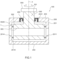
- Fig. 1 is a vertical sectional view of a switching device 100 provided with a sealing device 1 according to an embodiment of the present disclosure
- Fig. 2 is a lateral sectional view of the switching device 100
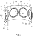
- Fig. 3 is a perspective view of a sealing device main body 2 of the sealing device 1
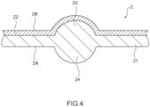
- Fig. 4 is a sectional view of the sealing device main body 2.
- the sealing device 1 is provided between a housing 200 in which a plurality of opening portions 2011 to 2016 are formed in a tubular inner peripheral surface 201A and a rotor 300 that is disposed inside the housing 200 and switches a flow path by rotating relative to the housing 200.
- the sealing device 1 includes a sealing device main body 2 that is disposed along the inner peripheral surface 201A and includes a sliding member provided on an inner surface 2B or an outer surface 2A.
- the sealing device main body 2 has a plurality of through-holes 231 to 235 that communicate with each of the plurality of opening portions 2011 to 2016, and the sealing device main body 2 is a strip plate-shaped member 6 with a flat plate shape that is bent and deformed.
- the switching device 100 provided with the sealing device 1 includes the housing 200, the rotor 300 serving as a valve body, a shaft seal 400, a motor 500, and the sealing device 1 and is used as a cooling water multi-way valve that switches a flow path of cooling water or the like in a vehicle, for example.
- the housing 200 includes a cylindrical tubular portion 201, a bottom surface portion 202 provided at one end of the tubular portion 201, and an upper surface portion 203 provided at the other end.
- a plurality of (six in the present embodiment) opening portions 2011 to 2016 are formed in a side surface of the tubular portion 201, and the opening portions 2011 to 2016 are connected to each device mounted in the vehicle via an appropriate fluid path.
- a through-hole 2031 through which a shaft portion 301 of the rotor 300 passes is formed in the upper surface portion 203.
- the rotor 300 has a shaft portion 301 extending in an axis x direction and a rotor main body 302 connected to an end portion of the shaft portion 301.
- a communication path 303 is formed that is disposed inside the housing 200 and is opened at two locations of an outer peripheral surface 302A.
- the shaft seal 400 is disposed between the through-hole 2031 and the shaft portion 301 and seals the housing 200.
- the motor 500 is connected at an end portion of the shaft portion 301 on the side opposite to the rotor main body 302 and causes the rotor 300 to rotate about the axis x. Note that although the housing 200 and the rotor 300 relatively rotate as the rotor 300 rotates in the present embodiment, a configuration in which the housing rotates may be employed, or a configuration in which both of them rotate may be employed.
- the amount of rotation of the motor 500 is controlled by a control device (not illustrated).
- a control device not illustrated.
- each of both end portions of the communication path 303 communicates with a predetermined opening portion from among the plurality of opening portions 2011 to 2016.
- two of the plurality of opening portions 2011 to 2016 communicate via the communication path 303, and the two communicating opening portions are switched by rotation of the motor 500. Therefore, an in-vehicle device as a target to which a fluid is directed or an order in which the fluid flows through a plurality of devices, for example, is switched.
- the sealing device 1 is provided between the inner peripheral surface 201A of the tubular portion 201 and the outer peripheral surface 302A of the rotor main body 302.
- a plurality of communication paths may be formed, and the shape of the communication path is not limited to a linear shape. Additionally, the plurality of opening portions may be formed to be aligned in the axis x direction in the housing.
- the sealing device 1 described below is compatible with the switching device 100 as schematically illustrated in Fig. 1 , and the number, the disposition, and the like of components of the sealing device may be appropriately set in accordance with the number, disposition, and the like of the opening portions in the switching device.
- the sealing device 1 including the sealing device main body 2 forms a sealing structure along with a bearing member 3.
- the sealing device main body 2 is disposed along the inner peripheral surface 201A and is formed into a C shape (that is, an opened annular shape) when seen in the axis x direction.
- the sealing device main body 2 also follows the outer peripheral surface 302A, and following the inner peripheral surface 201A is synonymous with following the outer peripheral surface 302A.
- the sealing device main body 2 has a two-layer structure having an elastic layer 21 formed of an elastic member and a sliding layer 22 formed of a sliding member, the outer surface 2A formed by the elastic layer 21 serves as a fixed surface, and the inner surface 2B formed by the sliding layer 22 serves as a sliding surface.
- the elastic member forming the elastic layer 21 is formed of a rubber material such as natural rubber or synthetic rubber, for example, an elastic resin may be used instead of the rubber material.
- the sliding member forming the sliding layer 22 is formed of a fluorine resin material such as PTFE, for example.
- the sealing device main body 2 has the through-holes 231 to 235, the number of which is smaller than the number of opening portions 2011 to 2016 of the housing 200 by one, and bead portions 24 and 25 that are formed around the through-holes 231 to 235 and project from both surfaces.
- Each of the plurality of through-holes 231 to 235 is disposed to overlap the opening portions 2011 to 2015, respectively, and the opening portions 2011 to 2015 are disposed inside the bead portions 24 on the side of the outer surface.
- the openings of the communication path 303 are disposed inside the bead portions 25 on the side of the inner surface when the communication path 303 communicates with the opening portions 2011 to 2015.
- the bead portions 24 and 25 have curved surface shapes, that is, shapes in which distal ends do not have corner parts, as illustrated in Fig. 4 (the sectional view along the line A-A in Fig. 3 ). In this manner interference between the sealing device main body 2 and the flow path is curbed.
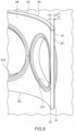
- Gate marks 26 for injecting rubber may be formed in the outer surface 2A of the sealing device main body 2 as illustrated in Fig. 5 .
- the gate marks 26 being formed on the outer surface 2A that is the fixed surface rather than the sliding surface in this manner, the rotor 300 and protrusions and the like around the gate marks 26 do not cause interference, and it is possible to curb the protrusions and the like around the gate marks 26 affecting (particularly, adversely affecting) rotation, swinging, and the like of the rotor.
- the gate marks 26 are disposed at vertexes of a quadrangular so as to surround the through-holes 231 to 235 in the illustrated example, the disposition of the gate marks may be appropriately set. Also, gate marks may not be formed depending on a molding method.
- the sealing device main body 2 formed into a C shape has a pair of end edge portions 2C and 2D extending in a circumferential direction around the axis x and end edge portions (that is, end edge portions facing each other) 2E and 2F extending along the axis x direction.
- the sliding layer 22 is folded outward at the end edge portions 2E and 2F, and the elastic layer 21 is covered.
- the sliding member is provided in a region corresponding to half or more from the side of the inner surface 2B at the end edge portions 2E and 2F, and a length L1 of the range where the sliding member is provided at the end edge portions 2E and 2F is half or more a thickness T1 of the end edge portions 2E and 2F.
- the thickness of the sliding layer 22 is smaller than the thickness of the elastic layer 21 at parts other than the end edge portions 2E and 2F and is preferably 30% or less of the thickness T1. This facilitates formation of the bead portions 24 and 25 by molds 601 and 602 as will be described later.
- the bearing member 3 has a through-hole 31 that is formed into an arc shape when seen in the axis x direction, has an outer peripheral surface fixed to the housing 200, and communicates with the opening portion 2016 and a sliding surface 32 that faces the inside of the housing 200.
- the bearing member 3 is formed of a harder member than the sealing device main body 2, and the sealing device main body 2 is more easily deformed than the bearing member 3. Note that the bearing member 3 may be formed integrally with the housing 200.
- the C-shaped sealing device main body 2 and the arc-shaped bearing member 3 form the sealing device 1 having an annular shape as a whole.
- rotation of the sealing device main body 2 is restricted by the sealing device main body 2 abutting the bearing member 3 fixed to the housing 200 from the circumferential direction.
- the sealing device main body 2 (particularly, the bead portions 24 and 25) are mainly compressed and deformed when the annular sealing device 1 is disposed between the inner peripheral surface 201A of the tubular portion 201 and the outer peripheral surface 302A of the rotor main body 302.
- the dimension of the sealing device main body 2 in the circumferential direction with respect to the dimension of the entire sealing device 1 in the circumferential direction is 75% or more, for example, in the present embodiment.
- molding is achieved by stacking a rubber material 4 and a sheet 5 made of a fluorine resin, pinching them with a pair of molds 601 and 602, and applying pressure to them.
- Recessed parts 601A and 602A are formed in the molds 601 and 602, such that the bead portions 24 and 25 are formed by the recessed parts 601A and 602A.
- an end portion of the sheet 5 is folded back about 90° such that the sliding layer 22 can cover the elastic layer 21 as described above.
- Fig. 7 schematically illustrates a state where the rubber material 4 is disposed between the molds 601 and 602 with the molds 601 and 602 kept in an open state
- the rubber material may be injected in a mold clamping state, and in this case, paths for injecting rubber (gate holes) are formed in the recessed parts 601A and 602A, and the gate marks 26 as described above are formed in the rubber after the molding.
- pressurizing and heating timings and a rubber injection timing may be appropriately set. It is possible to mold the rubber in a state where the sheet 5 made of a fluorine resin is fixed by injecting the rubber material in the rubber clamping state, and disposition of the sheet 5 at an appropriate position with respect to the sealing device main body 2 is facilitated.
- a strip-shaped member in which the fluorine resin material and the rubber material are chemically attached and stacked is formed through molding using the molds 601 and 602 as described above.
- the strip plate-shaped member 6 as illustrated in Fig. 8 is formed by performing punching on such a strip-shaped member as needed.
- the strip plate-shaped member 6 has a plurality of through-holes 231 to 235. At this time, the strip plate-shaped member 6 may not be a completely flat plate and may have slight warpage.
- the C-shaped sealing device main body 2 is formed by bending and deforming the strip plate-shaped member 6 to follow the circumference.
- the strip plate-shaped member 6 may be wound around the outer peripheral surface 302A of the rotor main body 302 and may then be inserted into the housing 200, or the strip plate-shaped member 6 may be bent and deformed to follow the inner peripheral surface 201A of the tubular portion 201, and the rotor main body 302 may then be inserted, or a jig may be used to bend and deform the strip plate-shaped member 6.
- the longitudinal dimension of the entire strip plate-shaped member 6 before the bending and deformation is set to be equal to the peripheral length of the inner surface 2B after the bending and deformation (substantially equal to the peripheral length of the outer peripheral surface 302A of the rotor 300).
- the longitudinal dimension of the entire strip plate-shaped member before the bending and deformation may be set to be equal to the peripheral length of the outer surface after the bending and deformation.
- the sealing device main body 2 formed as described above tends to be restored to become closer to the flat plate shape which is the original shape
- the sealing device main body 2 may be difficult to be restored in a case where it has been bent and deformed for a long period of time.
- the fluorine resin member tends to be restored to the original state.
- the sealing device main body 2 is deformed to become closer to the flat plate shape.
- the sealing device main body 2 is the strip plate-shaped member 6 that is bent and deformed, and it is thus possible to form the sealing device main body 2 through bending and deforming after the through-holes 231 to 235 are formed in the strip plate-shaped member 6 with a flat plate shape or a significantly large curvature radius. In this manner, it is possible to easily form the through-holes 231 to 235 while providing the sliding member, to easily manufacture the sealing device 1, and to achieve a reduction in friction.
- the sealing device main body 2 has the bead portions 24 and 25 projecting from both surfaces, and it is thus possible to improve a contact pressure with respect to the housing and the rotor 300 and to easily secure sealability. It is possible to reduce the number of manufacturing processes as compared with a method in which the pressurization molding and the molding of the bead portions are performed in separate processes, by forming such bead portions 24 and 25 when pressure is applied to the rubber material and the fluorine resin sheet.
- the sliding member is provided in a region corresponding to half or more from the side of the inner surface 2B on which the sliding member is provided at the end edge portions 2E and 2F, and it is thus possible to achieve a reduction in friction even in a case where the end edge portions 2E and 2F and the rotor 300 cause interference.
- Fig. 9 is a flowchart for explaining a method for manufacturing the sealing device main body 2 according to the present embodiment.
- the strip plate-shaped member 6 with a plate shape including the sliding layer 22 provided on one surface side is formed by stacking the rubber material 4 and the sheet 5 made of a fluorine resin, pinching them with the pair of molds 601 and 602, and applying pressure (see Fig. 7 ) (Step S101).
- Step S102 The through-holes 231 to 235 are formed in the strip plate-shaped member 6 after the strip plate-shaped member 6 is formed. Note that Step S102 may be performed when the strip plate-shaped member 6 is formed.
- the strip plate-shaped member 6 is bent and deformed, and the C-shaped sealing device main body 2 is thereby formed (Step S103).
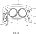
- the sealing device main body 2 is formed by bending and deforming the strip plate-shaped member 6 in the above embodiment, a holding member 7 to maintain the bent and deformed state may be provided as illustrated in Fig. 10 .
- the holding member 7 is formed into a C shape and holds end edge portions 2C and 2D of the sealing device main body 2.
- the holding member 7 may be accommodated in the housing 200 along with the sealing device main body 2, or may be detached when the sealing device main body 2 is accommodated in the housing 200 and may be used as a jig.
- the sealing device main body 2 may be accommodated in the housing 200, and only the holding member 7 on the side of the upper surface portion 203 out of the pair of holding member 7 may be detached.
- sealing device main body 2 is restored into the flat plate shape when it is taken out of the housing 200 and is then heated in the above embodiment, a sliding member that is unlikely to be deformed by heating, for example, may be used.
- the bead portions 24 and 25 are formed on the outer surface 2A and the inner surface 2B of the sealing device main body 2 in the above embodiment, the bead portions may be provided only on one surface, and no bead portions may be provided on either surface in a case where it is easy to curb leakage of a fluid with a material, a contact pressure, or the like of the sealing device main body.
- the sliding layer 22 is folded back outward at the end edge portions 2E and 2F in the above embodiment, the sliding layer 22 may not be folded back in a configuration in which, for example, the sliding layer 22 is formed to be thick such that only the sliding member contacts when the corner portion of the end edge portion 2E on the side of the inner surface 2B interferes with the rotor 300.
- the region where the sliding member is provided at the end edge portions 2E and 2F may be less than half the thickness T1.
- the bead portions 24 and 25 are formed when pressure is applied to the rubber material and the fluorine resin sheet in the above embodiment, the bead portions may be formed after a plate-shaped member is molded by applying pressure. With such a configuration, it is possible to freely set the shape of the bead portions.
- the timing at which the bead portions are formed and the timing at which the through-holes are formed may be appropriately set, and in a case where the bead portions are molded by using the molds as in the above embodiment, for example, sites for forming the through-holes may be provided in the molds, and the bead portions and the through-holes may be formed at the same time.
- the strip plate-shaped member 6 is formed by stacking the rubber material and the fluorine resin sheet and applying pressure by the molds 601 and 602 in the above embodiment
- the method for manufacturing the strip plate-shaped member is not limited thereto, and an appropriate method may be employed in accordance with a material and the like of the elastic member that serves as a base material.
- the strip plate-shaped member may be molded by attaching a sheet-shaped sliding member to a rubber plate or an elastic resin plate and performing working such as cutting or punching.
- the attachment between the elastic layer and the sliding layer is not limited to chemical attachment by a surface treatment or an adhesive, and physical adhesion and the like by surface working or an adhesion is appropriately selected.
- the sealing device 1 includes the sealing device main body 2 and the bearing member 3 in the above embodiment, the sealing device may not include the bearing member. If the number of through-holes in the sealing device main body is equal to the number of opening portions formed in the housing, the bearing member is not needed. Also, in a case where the number of through-holes in the sealing device main body is smaller than the number of opening portions formed in the housing by one, one of the opening portions in the housing does not overlap any through-holes in the sealing device main body, and the opening portion is sectioned from the other opening portions by the sealing device main body such that communication is not established. Therefore, the bearing member may not be provided.
- the number of through-holes in the sealing main body is smaller than the number of opening portions formed in the housing by two or more, it is necessary to provide a bearing member having one or more through-holes. Since the bearing member is less likely to be deformed than the sealing device main body, the bearing member is unlikely to become a resistance when the rotor rotates. Therefore, although it is possible to further reduce a torque as the dimension of the sealing device main body in the circumferential direction is shorter with respect to the peripheral length of the inner peripheral surface of the housing, the dimension of the sealing device main body in the circumferential direction is preferably 50% or more of the peripheral length of the inner peripheral surface of the housing and is more preferably 75% or more as in the above embodiment.
- the dimension of the sealing device main body in the circumferential direction may be less than 50% of the peripheral length of the inner peripheral surface of the housing.
- the inner peripheral surface 201A of the housing 200 has a cylindrical shape in the above embodiment, it is only necessary for the inner peripheral surface of the housing to have a tubular shape.
- the inner peripheral surface of the housing may be inclined with respect to the axial line (that is, it may have a truncated cone shape), or may have an arc shape in a section including the axial line (that is, it may have a shape corresponding to a ball valve).
- the strip plate-shaped member it is only necessary for the strip plate-shaped member to have the shape before the bending and deformation such that the strip plate-shaped member follows the inner peripheral surface of the housing by being bent and deformed.
- the inner surface 2B of the sealing device main body 2 serves as the sliding surface and the outer surface 2A serves as the fixed surface in the above embodiment
- the inner surface may be caused to serve as a fixed surface and the outer surface may be caused to serve as a sliding surface by providing the sliding member only on the outer surface.
- a configuration in which the sealing device main body follows the rotor (valve body) may be employed.
- the present disclosure is not limited to the sealing device according to the embodiment of the present disclosure and includes all aspects included in the concept and the scope of the claims of the present disclosure.
- each configuration may be appropriately and selectively combined to achieve at least a part of the aforementioned object and effects.
- the shape, the material, the disposition, the size, and the like of each component in the above embodiment may be appropriately changed in accordance with a specific utilization aspect of the present disclosure.
Landscapes
- Engineering & Computer Science (AREA)
- General Engineering & Computer Science (AREA)
- Mechanical Engineering (AREA)
- Manufacturing & Machinery (AREA)
- Sealing Devices (AREA)
- Taps Or Cocks (AREA)
Abstract
Provided are a sealing device that can be easily manufactured and achieve a reduction in friction and a method for manufacturing the sealing device. A sealing device 1 is provided between a housing 200 in which a plurality of opening portions 2011 to 2016 are formed in a tubular inner peripheral surface 201A and a rotor 300 that is disposed in the housing 200 and switches a flow path by rotating relative to the housing 200. The sealing device 1 includes a sealing device main body 2 that is disposed along the inner peripheral surface 201A and includes a sliding member provided on an inner surface 2B or an outer surface 2A. The sealing device main body 2 has a plurality of through-holes 231 to 235 that communicate with each of the plurality of openings 2011 to 2016, and the sealing device main body is a strip plate-shaped member 6 with a flat plate shape that is bent and deformed.
Description
- The present disclosure relates to a sealing device and a method for manufacturing a sealing device.
- In general, a switching device including a housing in which a plurality of ports are formed and a valve body that is disposed inside the housing and has a communication path, the switching device being adapted to switch a combination of ports for which communication is to be established by a communication path with the valve body rotated, that is, adapted to switch a flow path, is known. As such a switching device, a switching device with an O-ring provided between a main body serving as a housing and a valve body has been proposed (see
Japanese Patent Laid-Open No. 2013-92176 Japanese Patent Laid-Open No. 2013-92176 - A reduction in friction (that is, to reduce a sliding resistance) has been desired for a device that causes a valve body to rotate with respect to a housing as described in
Japanese Patent Laid-Open No. 2013-92176 - The present disclosure is related to providing a sealing device that can be easily manufactured and can achieve a reduction in friction, and a method for manufacturing the sealing device.
- In accordance with an aspect of the present disclosure, there is provided a sealing device that is provided between a housing in which a plurality of opening portions are formed in a tubular inner peripheral surface and a valve body that is disposed inside the housing and switches a flow path by rotating relative to the housing, the sealing device including: a sealing device main body that is disposed along the inner peripheral surface and includes a sliding member provided on an inner surface or an outer surface, in which the sealing device main body has a plurality of through-holes that communicate with each of the plurality of opening portions, the sealing device main body being a strip plate-shaped member with a flat plate shape that is bent and deformed.
- In the sealing device according to an aspect of the present disclosure, the sealing device main body is restored to become closer to the flat plate shape when the sealing device main body is taken out of the housing and is heated.
- In the sealing device according to an aspect of the present disclosure, the sealing device main body has, around the through-holes, bead portions projecting from the inner surface and the outer surface.
- In the sealing device according to an aspect of the present disclosure, a surface of the sealing device main body on a side opposite to a surface provided with the sliding member is formed of a rubber material and has gate marks for rubber flowing.
- In the sealing device according to an aspect of the present disclosure, an end edge portion of the sealing device main body extending in an axial direction is provided with a sliding member over a region corresponding to half or more from a side of a surface provided with the sliding member.
- A method for manufacturing a sealing device according to the present disclosure is a method for manufacturing a sealing device that is provided between a housing in which a plurality of opening portions are formed in a tubular inner peripheral surface and a rotor that is disposed inside the housing and rotates relative to the housing, the method including: forming a strip plate-shaped member with a plate shape that includes a sliding member provided on a side of one surface; forming through-holes in the strip plate-shaped member during formation or after formation of the strip plate-shaped member; and bending and deforming the strip plate-shaped member into a shape along the inner peripheral surface.
- In the method for manufacturing a sealing device according to an aspect of the present disclosure, the strip plate-shaped member is molded by stacking a rubber material and a fluorine resin sheet and applying pressure in a stacking direction.
- In the method for manufacturing a sealing device according to an aspect of the present disclosure, when the pressure is applied to the rubber material and the fluorine resin sheet, bead portions projecting from both surfaces are formed around the through-holes in the strip plate-shaped member or around positions where the through-holes are to be formed.
- In the method for manufacturing a sealing device according to an aspect of the present disclosure, pressure is applied to the rubber material and the fluorine resin sheet by using a mold having a rubber injection portion.
- According to the sealing device and a method for manufacturing a sealing device of the present disclosure, it is possible to easily manufacture the sealing device and to achieve a reduction in friction.
-
-
Fig. 1 is a vertical sectional view of a switching device provided with a sealing device according to an embodiment of the present disclosure; -
Fig. 2 is a lateral sectional view of the switching device provided with the sealing device according to the embodiment of the present disclosure; -
Fig. 3 is a perspective view of a sealing device main body of the sealing device according to the embodiment of the present disclosure; -
Fig. 4 is a sectional view of the sealing device main body of the sealing device according to the embodiment of the present disclosure; -
Fig. 5 is a perspective view of the sealing device main body of the sealing device according to the embodiment of the present disclosure; -
Fig. 6 is an enlarged view of the sealing device main body of the sealing device according to the embodiment of the present disclosure; -
Fig. 7 is a sectional view illustrating a manufacturing process of the sealing device main body of the sealing device according to the embodiment of the present disclosure; -
Fig. 8 is a perspective view of a strip plate-shaped member of the sealing device according to the embodiment of the present disclosure; -
Fig. 9 is a flowchart for explaining a method for manufacturing the sealing device main body according to the present embodiment; and -
Fig. 10 is a perspective view of a sealing device main body of a sealing device according to a modification example of the present disclosure. - Hereinafter, an embodiment of the present disclosure will be described with reference to drawings.
Fig. 1 is a vertical sectional view of aswitching device 100 provided with asealing device 1 according to an embodiment of the present disclosure,Fig. 2 is a lateral sectional view of theswitching device 100,Fig. 3 is a perspective view of a sealing devicemain body 2 of thesealing device 1, andFig. 4 is a sectional view of the sealing devicemain body 2. - As illustrated in
Figs. 1 to 4 , thesealing device 1 according to the embodiment of the present disclosure is provided between ahousing 200 in which a plurality ofopening portions 2011 to 2016 are formed in a tubular innerperipheral surface 201A and arotor 300 that is disposed inside thehousing 200 and switches a flow path by rotating relative to thehousing 200. Thesealing device 1 includes a sealing devicemain body 2 that is disposed along the innerperipheral surface 201A and includes a sliding member provided on aninner surface 2B or anouter surface 2A. The sealing devicemain body 2 has a plurality of through-holes 231 to 235 that communicate with each of the plurality ofopening portions 2011 to 2016, and the sealing devicemain body 2 is a strip plate-shaped member 6 with a flat plate shape that is bent and deformed. - The
switching device 100 provided with thesealing device 1 includes thehousing 200, therotor 300 serving as a valve body, ashaft seal 400, amotor 500, and thesealing device 1 and is used as a cooling water multi-way valve that switches a flow path of cooling water or the like in a vehicle, for example. - The
housing 200 includes a cylindricaltubular portion 201, abottom surface portion 202 provided at one end of thetubular portion 201, and anupper surface portion 203 provided at the other end. A plurality of (six in the present embodiment) openingportions 2011 to 2016 are formed in a side surface of thetubular portion 201, and theopening portions 2011 to 2016 are connected to each device mounted in the vehicle via an appropriate fluid path. A through-hole 2031 through which ashaft portion 301 of therotor 300 passes is formed in theupper surface portion 203. - The
rotor 300 has ashaft portion 301 extending in an axis x direction and a rotormain body 302 connected to an end portion of theshaft portion 301. In the rotormain body 302, acommunication path 303 is formed that is disposed inside thehousing 200 and is opened at two locations of an outerperipheral surface 302A. Theshaft seal 400 is disposed between the through-hole 2031 and theshaft portion 301 and seals thehousing 200. Themotor 500 is connected at an end portion of theshaft portion 301 on the side opposite to the rotormain body 302 and causes therotor 300 to rotate about the axis x. Note that although thehousing 200 and therotor 300 relatively rotate as therotor 300 rotates in the present embodiment, a configuration in which the housing rotates may be employed, or a configuration in which both of them rotate may be employed. - The amount of rotation of the
motor 500 is controlled by a control device (not illustrated). In this manner, each of both end portions of thecommunication path 303 communicates with a predetermined opening portion from among the plurality ofopening portions 2011 to 2016. In other words, two of the plurality ofopening portions 2011 to 2016 communicate via thecommunication path 303, and the two communicating opening portions are switched by rotation of themotor 500. Therefore, an in-vehicle device as a target to which a fluid is directed or an order in which the fluid flows through a plurality of devices, for example, is switched. - In order to have the plurality of
opening portions 2011 to 2016 as described above as independent components (so as not to communicate with each other except through the communication path 303), thesealing device 1 is provided between the innerperipheral surface 201A of thetubular portion 201 and the outerperipheral surface 302A of the rotormain body 302. - Note that although only one
communication path 303 is illustrated inFigs. 1 and2 , a plurality of communication paths may be formed, and the shape of the communication path is not limited to a linear shape. Additionally, the plurality of opening portions may be formed to be aligned in the axis x direction in the housing. Thesealing device 1 described below is compatible with theswitching device 100 as schematically illustrated inFig. 1 , and the number, the disposition, and the like of components of the sealing device may be appropriately set in accordance with the number, disposition, and the like of the opening portions in the switching device. - The
sealing device 1 including the sealing devicemain body 2 forms a sealing structure along with abearing member 3. The sealing devicemain body 2 is disposed along the innerperipheral surface 201A and is formed into a C shape (that is, an opened annular shape) when seen in the axis x direction. Also, the sealing devicemain body 2 also follows the outerperipheral surface 302A, and following the innerperipheral surface 201A is synonymous with following the outerperipheral surface 302A. As illustrated inFig. 4 , the sealing devicemain body 2 has a two-layer structure having anelastic layer 21 formed of an elastic member and a slidinglayer 22 formed of a sliding member, theouter surface 2A formed by theelastic layer 21 serves as a fixed surface, and theinner surface 2B formed by the slidinglayer 22 serves as a sliding surface. - Although the elastic member forming the
elastic layer 21 is formed of a rubber material such as natural rubber or synthetic rubber, for example, an elastic resin may be used instead of the rubber material. The sliding member forming the slidinglayer 22 is formed of a fluorine resin material such as PTFE, for example. - The sealing device
main body 2 has the through-holes 231 to 235, the number of which is smaller than the number ofopening portions 2011 to 2016 of thehousing 200 by one, and beadportions holes 231 to 235 and project from both surfaces. Each of the plurality of through-holes 231 to 235 is disposed to overlap theopening portions 2011 to 2015, respectively, and theopening portions 2011 to 2015 are disposed inside thebead portions 24 on the side of the outer surface. The openings of thecommunication path 303 are disposed inside thebead portions 25 on the side of the inner surface when thecommunication path 303 communicates with theopening portions 2011 to 2015. - The
bead portions Fig. 4 (the sectional view along the line A-A inFig. 3 ). In this manner interference between the sealing devicemain body 2 and the flow path is curbed. - Gate marks 26 for injecting rubber may be formed in the
outer surface 2A of the sealing devicemain body 2 as illustrated inFig. 5 . By the gate marks 26 being formed on theouter surface 2A that is the fixed surface rather than the sliding surface in this manner, therotor 300 and protrusions and the like around the gate marks 26 do not cause interference, and it is possible to curb the protrusions and the like around the gate marks 26 affecting (particularly, adversely affecting) rotation, swinging, and the like of the rotor. Although the gate marks 26 are disposed at vertexes of a quadrangular so as to surround the through-holes 231 to 235 in the illustrated example, the disposition of the gate marks may be appropriately set. Also, gate marks may not be formed depending on a molding method. - The sealing device
main body 2 formed into a C shape has a pair ofend edge portions Fig. 6 , the slidinglayer 22 is folded outward at theend edge portions elastic layer 21 is covered. In this manner, the sliding member is provided in a region corresponding to half or more from the side of theinner surface 2B at theend edge portions end edge portions end edge portions layer 22 is smaller than the thickness of theelastic layer 21 at parts other than theend edge portions bead portions molds - The bearing
member 3 has a through-hole 31 that is formed into an arc shape when seen in the axis x direction, has an outer peripheral surface fixed to thehousing 200, and communicates with theopening portion 2016 and a slidingsurface 32 that faces the inside of thehousing 200. The bearingmember 3 is formed of a harder member than the sealing devicemain body 2, and the sealing devicemain body 2 is more easily deformed than the bearingmember 3. Note that the bearingmember 3 may be formed integrally with thehousing 200. - The C-shaped sealing device
main body 2 and the arc-shapedbearing member 3 form thesealing device 1 having an annular shape as a whole. At this time, rotation of the sealing devicemain body 2 is restricted by the sealing devicemain body 2 abutting the bearingmember 3 fixed to thehousing 200 from the circumferential direction. The sealing device main body 2 (particularly, thebead portions 24 and 25) are mainly compressed and deformed when theannular sealing device 1 is disposed between the innerperipheral surface 201A of thetubular portion 201 and the outerperipheral surface 302A of the rotormain body 302. Also, the dimension of the sealing devicemain body 2 in the circumferential direction with respect to the dimension of theentire sealing device 1 in the circumferential direction is 75% or more, for example, in the present embodiment. - Here, a method for manufacturing the sealing device
main body 2 will be described. As illustrated inFig. 7 , molding is achieved by stacking arubber material 4 and asheet 5 made of a fluorine resin, pinching them with a pair ofmolds parts molds bead portions parts sheet 5 is folded back about 90° such that the slidinglayer 22 can cover theelastic layer 21 as described above. - Although
Fig. 7 schematically illustrates a state where therubber material 4 is disposed between themolds molds parts sheet 5 made of a fluorine resin is fixed by injecting the rubber material in the rubber clamping state, and disposition of thesheet 5 at an appropriate position with respect to the sealing devicemain body 2 is facilitated. - A strip-shaped member in which the fluorine resin material and the rubber material are chemically attached and stacked is formed through molding using the
molds member 6 as illustrated inFig. 8 is formed by performing punching on such a strip-shaped member as needed. The strip plate-shapedmember 6 has a plurality of through-holes 231 to 235. At this time, the strip plate-shapedmember 6 may not be a completely flat plate and may have slight warpage. - Thereafter, the C-shaped sealing device
main body 2 is formed by bending and deforming the strip plate-shapedmember 6 to follow the circumference. At this time, the strip plate-shapedmember 6 may be wound around the outerperipheral surface 302A of the rotormain body 302 and may then be inserted into thehousing 200, or the strip plate-shapedmember 6 may be bent and deformed to follow the innerperipheral surface 201A of thetubular portion 201, and the rotormain body 302 may then be inserted, or a jig may be used to bend and deform the strip plate-shapedmember 6. - If the strip plate-shaped
member 6 with a flat plate shape is bent and deformed as described above, a difference in the peripheral length occurs between the inner peripheral surface and the outer peripheral surface in accordance with the thickness of the strip plate-shapedmember 6. At this time, since therubber material 4 is more likely to respond to expansion and contraction than thesheet 5 made of a fluorine resin, the longitudinal dimension of the entire strip plate-shapedmember 6 before the bending and deformation is set to be equal to the peripheral length of theinner surface 2B after the bending and deformation (substantially equal to the peripheral length of the outerperipheral surface 302A of the rotor 300). Not that in a case where the outer surface of the sealing device main body serves as a sliding surface as will be described later, the longitudinal dimension of the entire strip plate-shaped member before the bending and deformation may be set to be equal to the peripheral length of the outer surface after the bending and deformation. - Although once the sealing device
main body 2 formed as described above is taken out of thehousing 200, the sealing devicemain body 2 tends to be restored to become closer to the flat plate shape which is the original shape, the sealing devicemain body 2 may be difficult to be restored in a case where it has been bent and deformed for a long period of time. In such a case as well, if the extracted sealing devicemain body 2 is heated to such an extent that the fluorine resin is not melted, the fluorine resin member tends to be restored to the original state. In this manner, the sealing devicemain body 2 is deformed to become closer to the flat plate shape. At this time, it is not necessary for the sealing devicemain body 2 to be restored completely to the flat plate shape, and it is only necessary to become closer to the flat plate shape than the state at the time of the extraction. - According to the
sealing device 1 of the embodiment of the present disclosure, the sealing devicemain body 2 is the strip plate-shapedmember 6 that is bent and deformed, and it is thus possible to form the sealing devicemain body 2 through bending and deforming after the through-holes 231 to 235 are formed in the strip plate-shapedmember 6 with a flat plate shape or a significantly large curvature radius. In this manner, it is possible to easily form the through-holes 231 to 235 while providing the sliding member, to easily manufacture thesealing device 1, and to achieve a reduction in friction. - Also, the sealing device
main body 2 has thebead portions rotor 300 and to easily secure sealability. It is possible to reduce the number of manufacturing processes as compared with a method in which the pressurization molding and the molding of the bead portions are performed in separate processes, by formingsuch bead portions - Also, the sliding member is provided in a region corresponding to half or more from the side of the
inner surface 2B on which the sliding member is provided at theend edge portions end edge portions rotor 300 cause interference. -
Fig. 9 is a flowchart for explaining a method for manufacturing the sealing devicemain body 2 according to the present embodiment. As illustrated inFig. 9 , the strip plate-shapedmember 6 with a plate shape including the slidinglayer 22 provided on one surface side is formed by stacking therubber material 4 and thesheet 5 made of a fluorine resin, pinching them with the pair ofmolds Fig. 7 ) (Step S101). - The through-
holes 231 to 235 are formed in the strip plate-shapedmember 6 after the strip plate-shapedmember 6 is formed (Step S102). Note that Step S102 may be performed when the strip plate-shapedmember 6 is formed. - The strip plate-shaped
member 6 is bent and deformed, and the C-shaped sealing devicemain body 2 is thereby formed (Step S103). - Note that the present disclosure is not limited to the above embodiment, includes other configurations and the like with which the object of the present disclosure can be achieved, and also includes modifications and the like described below. For example, although the sealing device
main body 2 is formed by bending and deforming the strip plate-shapedmember 6 in the above embodiment, a holdingmember 7 to maintain the bent and deformed state may be provided as illustrated inFig. 10 . The holdingmember 7 is formed into a C shape and holdsend edge portions main body 2. The holdingmember 7 may be accommodated in thehousing 200 along with the sealing devicemain body 2, or may be detached when the sealing devicemain body 2 is accommodated in thehousing 200 and may be used as a jig. Also, the sealing devicemain body 2 may be accommodated in thehousing 200, and only the holdingmember 7 on the side of theupper surface portion 203 out of the pair of holdingmember 7 may be detached. - Also, although the sealing device
main body 2 is restored into the flat plate shape when it is taken out of thehousing 200 and is then heated in the above embodiment, a sliding member that is unlikely to be deformed by heating, for example, may be used. - Although the
bead portions outer surface 2A and theinner surface 2B of the sealing devicemain body 2 in the above embodiment, the bead portions may be provided only on one surface, and no bead portions may be provided on either surface in a case where it is easy to curb leakage of a fluid with a material, a contact pressure, or the like of the sealing device main body. - Furthermore, although the sliding
layer 22 is folded back outward at theend edge portions layer 22 may not be folded back in a configuration in which, for example, the slidinglayer 22 is formed to be thick such that only the sliding member contacts when the corner portion of theend edge portion 2E on the side of theinner surface 2B interferes with therotor 300. In such a case, the region where the sliding member is provided at theend edge portions - Moreover, although the
bead portions - Also, the timing at which the bead portions are formed and the timing at which the through-holes are formed may be appropriately set, and in a case where the bead portions are molded by using the molds as in the above embodiment, for example, sites for forming the through-holes may be provided in the molds, and the bead portions and the through-holes may be formed at the same time.
- Also, although the strip plate-shaped
member 6 is formed by stacking the rubber material and the fluorine resin sheet and applying pressure by themolds - Although the
sealing device 1 includes the sealing devicemain body 2 and the bearingmember 3 in the above embodiment, the sealing device may not include the bearing member. If the number of through-holes in the sealing device main body is equal to the number of opening portions formed in the housing, the bearing member is not needed. Also, in a case where the number of through-holes in the sealing device main body is smaller than the number of opening portions formed in the housing by one, one of the opening portions in the housing does not overlap any through-holes in the sealing device main body, and the opening portion is sectioned from the other opening portions by the sealing device main body such that communication is not established. Therefore, the bearing member may not be provided. - Also, in a case where the number of through-holes in the sealing main body is smaller than the number of opening portions formed in the housing by two or more, it is necessary to provide a bearing member having one or more through-holes. Since the bearing member is less likely to be deformed than the sealing device main body, the bearing member is unlikely to become a resistance when the rotor rotates. Therefore, although it is possible to further reduce a torque as the dimension of the sealing device main body in the circumferential direction is shorter with respect to the peripheral length of the inner peripheral surface of the housing, the dimension of the sealing device main body in the circumferential direction is preferably 50% or more of the peripheral length of the inner peripheral surface of the housing and is more preferably 75% or more as in the above embodiment. Note that in a case where it is easy to assemble the rotor, or in a case where it is possible to secure stability of rotation, for example, the dimension of the sealing device main body in the circumferential direction may be less than 50% of the peripheral length of the inner peripheral surface of the housing.
- Although the inner
peripheral surface 201A of thehousing 200 has a cylindrical shape in the above embodiment, it is only necessary for the inner peripheral surface of the housing to have a tubular shape. In other words, the inner peripheral surface of the housing may be inclined with respect to the axial line (that is, it may have a truncated cone shape), or may have an arc shape in a section including the axial line (that is, it may have a shape corresponding to a ball valve). At this time, it is only necessary for the strip plate-shaped member to have the shape before the bending and deformation such that the strip plate-shaped member follows the inner peripheral surface of the housing by being bent and deformed. - Although the
inner surface 2B of the sealing devicemain body 2 serves as the sliding surface and theouter surface 2A serves as the fixed surface in the above embodiment, the inner surface may be caused to serve as a fixed surface and the outer surface may be caused to serve as a sliding surface by providing the sliding member only on the outer surface. In other words, a configuration in which the sealing device main body follows the rotor (valve body) may be employed. - Although the embodiment of the present disclosure has been described above, the present disclosure is not limited to the sealing device according to the embodiment of the present disclosure and includes all aspects included in the concept and the scope of the claims of the present disclosure. Also, each configuration may be appropriately and selectively combined to achieve at least a part of the aforementioned object and effects. For example, the shape, the material, the disposition, the size, and the like of each component in the above embodiment may be appropriately changed in accordance with a specific utilization aspect of the present disclosure.
Claims (9)
- A sealing device that is provided between a housing in which a plurality of opening portions are formed in a tubular inner peripheral surface and a valve body that is disposed inside the housing and switches a flow path by rotating relative to the housing, the sealing device comprising:a sealing device main body that is disposed along the inner peripheral surface and includes a sliding member provided on an inner surface or an outer surface,wherein the sealing device main body has a plurality of through-holes that communicate with each of the plurality of opening portions, the sealing device main body being a strip plate-shaped member with a flat plate shape that is bent and deformed.
- The sealing device according to claim 1, wherein the sealing device main body is restored to become closer to the flat plate shape when the sealing device main body is taken out of the housing and is heated.
- The sealing device according to claim 1 or 2, wherein the sealing device main body has, around the through-holes, bead portions projecting from the inner surface and the outer surface.
- The sealing device according to claim 1 or 2, wherein a surface of the sealing device main body on a side opposite to a surface provided with the sliding member is formed of a rubber material and has a gate mark for rubber flowing.
- The sealing device according to claim 1 or 2, wherein an end edge portion of the sealing device main body extending in an axial direction is provided with a sliding member over a region corresponding to half or more from a side of a surface provided with the sliding member.
- A method for manufacturing a sealing device that is provided between a housing in which a plurality of opening portions are formed in a tubular inner peripheral surface and a rotor that is disposed inside the housing and rotates relative to the housing, the method comprising:forming a strip plate-shaped member with a plate shape that includes a sliding member provided on a side of one surface;forming through-holes in the strip plate-shaped member during formation or after formation of the strip plate-shaped member; andbending and deforming the strip plate-shaped member into a shape along the inner peripheral surface.
- The method for manufacturing a sealing device according to claim 6, wherein the strip plate-shaped member is molded by stacking a rubber material and a fluorine resin sheet and applying pressure in a stacking direction.
- The method for manufacturing a sealing device according to claim 7, wherein when the pressure is applied to the rubber material and the fluorine resin sheet, bead portions projecting from both surfaces are formed around the through-holes in the strip plate-shaped member or around positions where the through-holes are to be formed.
- The method for manufacturing a sealing device according to claim 7 or 8, wherein pressure is applied to the rubber material and the fluorine resin sheet by using a mold having a rubber injection portion.
Applications Claiming Priority (1)
| Application Number | Priority Date | Filing Date | Title |
|---|---|---|---|
| JP2022127900A JP2024024915A (en) | 2022-08-10 | 2022-08-10 | Sealing device and method of manufacturing the sealing device |
Publications (1)
| Publication Number | Publication Date |
|---|---|
| EP4321781A1 true EP4321781A1 (en) | 2024-02-14 |
Family
ID=87556162
Family Applications (1)
| Application Number | Title | Priority Date | Filing Date |
|---|---|---|---|
| EP23189552.5A Pending EP4321781A1 (en) | 2022-08-10 | 2023-08-03 | Sealing device and method for manufacturing sealing device |
Country Status (4)
| Country | Link |
|---|---|
| US (1) | US12305760B2 (en) |
| EP (1) | EP4321781A1 (en) |
| JP (1) | JP2024024915A (en) |
| CN (1) | CN117588581A (en) |
Families Citing this family (2)
| Publication number | Priority date | Publication date | Assignee | Title |
|---|---|---|---|---|
| JP2025184563A (en) * | 2024-06-07 | 2025-12-18 | Nok株式会社 | Method for manufacturing a sealed structure and a sealed structure |
| JP2026017722A (en) * | 2024-07-24 | 2026-02-05 | Nok株式会社 | Sealing material |
Citations (5)
| Publication number | Priority date | Publication date | Assignee | Title |
|---|---|---|---|---|
| US3232579A (en) * | 1963-05-22 | 1966-02-01 | Westinghouse Air Brake Co | Angle cock |
| FR2827358A1 (en) * | 2001-07-11 | 2003-01-17 | Valeo Thermique Moteur Sa | Control valve for road vehicle engine fluid cooling circuits, has separated circular joint seals held together by longitudinal ribs which also act as seals |
| JP2013092176A (en) | 2011-10-24 | 2013-05-16 | Idea Link:Kk | Selector valve |
| EP2713083A1 (en) * | 2012-09-27 | 2014-04-02 | Systèmes Moteurs (Société par Actions Simplifiée) | Feed and control valve with rotary slide valve |
| US20190160910A1 (en) * | 2016-05-19 | 2019-05-30 | Denso Corporation | Flow passage switching valve |
Family Cites Families (1)
| Publication number | Priority date | Publication date | Assignee | Title |
|---|---|---|---|---|
| US3070974A (en) * | 1959-12-14 | 1963-01-01 | Garrett Corp | Single valve refrigeration control |
-
2022
- 2022-08-10 JP JP2022127900A patent/JP2024024915A/en active Pending
-
2023
- 2023-08-03 EP EP23189552.5A patent/EP4321781A1/en active Pending
- 2023-08-07 CN CN202310987356.8A patent/CN117588581A/en active Pending
- 2023-08-09 US US18/231,983 patent/US12305760B2/en active Active
Patent Citations (5)
| Publication number | Priority date | Publication date | Assignee | Title |
|---|---|---|---|---|
| US3232579A (en) * | 1963-05-22 | 1966-02-01 | Westinghouse Air Brake Co | Angle cock |
| FR2827358A1 (en) * | 2001-07-11 | 2003-01-17 | Valeo Thermique Moteur Sa | Control valve for road vehicle engine fluid cooling circuits, has separated circular joint seals held together by longitudinal ribs which also act as seals |
| JP2013092176A (en) | 2011-10-24 | 2013-05-16 | Idea Link:Kk | Selector valve |
| EP2713083A1 (en) * | 2012-09-27 | 2014-04-02 | Systèmes Moteurs (Société par Actions Simplifiée) | Feed and control valve with rotary slide valve |
| US20190160910A1 (en) * | 2016-05-19 | 2019-05-30 | Denso Corporation | Flow passage switching valve |
Also Published As
| Publication number | Publication date |
|---|---|
| JP2024024915A (en) | 2024-02-26 |
| US12305760B2 (en) | 2025-05-20 |
| US20240052928A1 (en) | 2024-02-15 |
| CN117588581A (en) | 2024-02-23 |
Similar Documents
| Publication | Publication Date | Title |
|---|---|---|
| EP4321781A1 (en) | Sealing device and method for manufacturing sealing device | |
| US5743169A (en) | Diaphragm assembly and method of manufacturing same | |
| EP1406036B1 (en) | Valve drive device | |
| CN115380182B (en) | Plug valve hard seal on cylindrical wall | |
| US5346662A (en) | Method of manufacturing a composite seal | |
| WO2020157834A1 (en) | Method for manufacturing seal ring, and seal ring | |
| US8793874B2 (en) | Method for manufacturing a petal valve | |
| GB1573440A (en) | Fluid control valves | |
| JP7815445B2 (en) | Sealing element, method for manufacturing a sealing element, and use of a sealing element manufactured by such a method - Patents.com | |
| KR101394494B1 (en) | Method for preparing liner of lined butterfly valve | |
| US4317558A (en) | Seat assembly for butterfly valve | |
| JP2005502007A (en) | Integrated seal for gas spring | |
| KR20050057103A (en) | Method for sealing a throttle valve support | |
| JP2017215026A (en) | Fluid valve and method of manufacturing the same | |
| JP2005171808A (en) | Throttle control device | |
| JP3890756B2 (en) | Sealing device | |
| JP2005188637A (en) | Boot for constant speed joint | |
| JP3508524B2 (en) | Sealing device manufacturing method and sealing device | |
| JPH1151202A (en) | Valve | |
| CN120569587A (en) | Flow path switching device | |
| JP3247565B2 (en) | Sealing device and manufacturing method thereof | |
| JP3743122B2 (en) | Sealing device | |
| JP2025005426A (en) | Rotary valve and method for manufacturing sealing member used in rotary valve | |
| US20060170141A1 (en) | Bellows with fastening mechanism | |
| JPH11325276A (en) | Flow path switching valve |
Legal Events
| Date | Code | Title | Description |
|---|---|---|---|
| PUAI | Public reference made under article 153(3) epc to a published international application that has entered the european phase |
Free format text: ORIGINAL CODE: 0009012 |
|
| STAA | Information on the status of an ep patent application or granted ep patent |
Free format text: STATUS: REQUEST FOR EXAMINATION WAS MADE |
|
| 17P | Request for examination filed |
Effective date: 20230803 |
|
| AK | Designated contracting states |
Kind code of ref document: A1 Designated state(s): AL AT BE BG CH CY CZ DE DK EE ES FI FR GB GR HR HU IE IS IT LI LT LU LV MC ME MK MT NL NO PL PT RO RS SE SI SK SM TR |