EP4321730A1 - Radial fan with leading edge air injection - Google Patents
Radial fan with leading edge air injection Download PDFInfo
- Publication number
- EP4321730A1 EP4321730A1 EP23189402.3A EP23189402A EP4321730A1 EP 4321730 A1 EP4321730 A1 EP 4321730A1 EP 23189402 A EP23189402 A EP 23189402A EP 4321730 A1 EP4321730 A1 EP 4321730A1
- Authority
- EP
- European Patent Office
- Prior art keywords
- rotor
- air
- leading edge
- extending
- internal channel
- Prior art date
- Legal status (The legal status is an assumption and is not a legal conclusion. Google has not performed a legal analysis and makes no representation as to the accuracy of the status listed.)
- Granted
Links
Images




Classifications
-
- F—MECHANICAL ENGINEERING; LIGHTING; HEATING; WEAPONS; BLASTING
- F01—MACHINES OR ENGINES IN GENERAL; ENGINE PLANTS IN GENERAL; STEAM ENGINES
- F01D—NON-POSITIVE DISPLACEMENT MACHINES OR ENGINES, e.g. STEAM TURBINES
- F01D5/00—Blades; Blade-carrying members; Heating, heat-insulating, cooling or antivibration means on the blades or the members
- F01D5/02—Blade-carrying members, e.g. rotors
- F01D5/08—Heating, heat-insulating or cooling means
- F01D5/081—Cooling fluid being directed on the side of the rotor disc or at the roots of the blades
-
- F—MECHANICAL ENGINEERING; LIGHTING; HEATING; WEAPONS; BLASTING
- F01—MACHINES OR ENGINES IN GENERAL; ENGINE PLANTS IN GENERAL; STEAM ENGINES
- F01D—NON-POSITIVE DISPLACEMENT MACHINES OR ENGINES, e.g. STEAM TURBINES
- F01D5/00—Blades; Blade-carrying members; Heating, heat-insulating, cooling or antivibration means on the blades or the members
- F01D5/12—Blades
- F01D5/14—Form or construction
- F01D5/141—Shape, i.e. outer, aerodynamic form
- F01D5/145—Means for influencing boundary layers or secondary circulations
-
- F—MECHANICAL ENGINEERING; LIGHTING; HEATING; WEAPONS; BLASTING
- F01—MACHINES OR ENGINES IN GENERAL; ENGINE PLANTS IN GENERAL; STEAM ENGINES
- F01D—NON-POSITIVE DISPLACEMENT MACHINES OR ENGINES, e.g. STEAM TURBINES
- F01D5/00—Blades; Blade-carrying members; Heating, heat-insulating, cooling or antivibration means on the blades or the members
- F01D5/12—Blades
- F01D5/14—Form or construction
- F01D5/18—Hollow blades, i.e. blades with cooling or heating channels or cavities; Heating, heat-insulating or cooling means on blades
- F01D5/187—Convection cooling
-
- F—MECHANICAL ENGINEERING; LIGHTING; HEATING; WEAPONS; BLASTING
- F04—POSITIVE - DISPLACEMENT MACHINES FOR LIQUIDS; PUMPS FOR LIQUIDS OR ELASTIC FLUIDS
- F04D—NON-POSITIVE-DISPLACEMENT PUMPS
- F04D29/00—Details, component parts, or accessories
- F04D29/66—Combating cavitation, whirls, noise, vibration or the like; Balancing
- F04D29/68—Combating cavitation, whirls, noise, vibration or the like; Balancing by influencing boundary layers
- F04D29/681—Combating cavitation, whirls, noise, vibration or the like; Balancing by influencing boundary layers especially adapted for elastic fluid pumps
- F04D29/684—Combating cavitation, whirls, noise, vibration or the like; Balancing by influencing boundary layers especially adapted for elastic fluid pumps by fluid injection
-
- B—PERFORMING OPERATIONS; TRANSPORTING
- B33—ADDITIVE MANUFACTURING TECHNOLOGY
- B33Y—ADDITIVE MANUFACTURING, i.e. MANUFACTURING OF THREE-DIMENSIONAL [3D] OBJECTS BY ADDITIVE DEPOSITION, ADDITIVE AGGLOMERATION OR ADDITIVE LAYERING, e.g. BY 3D PRINTING, STEREOLITHOGRAPHY OR SELECTIVE LASER SINTERING
- B33Y10/00—Processes of additive manufacturing
-
- B—PERFORMING OPERATIONS; TRANSPORTING
- B33—ADDITIVE MANUFACTURING TECHNOLOGY
- B33Y—ADDITIVE MANUFACTURING, i.e. MANUFACTURING OF THREE-DIMENSIONAL [3D] OBJECTS BY ADDITIVE DEPOSITION, ADDITIVE AGGLOMERATION OR ADDITIVE LAYERING, e.g. BY 3D PRINTING, STEREOLITHOGRAPHY OR SELECTIVE LASER SINTERING
- B33Y80/00—Products made by additive manufacturing
-
- B—PERFORMING OPERATIONS; TRANSPORTING
- B64—AIRCRAFT; AVIATION; COSMONAUTICS
- B64D—EQUIPMENT FOR FITTING IN OR TO AIRCRAFT; FLIGHT SUITS; PARACHUTES; ARRANGEMENT OR MOUNTING OF POWER PLANTS OR PROPULSION TRANSMISSIONS IN AIRCRAFT
- B64D13/00—Arrangements or adaptations of air-treatment apparatus for aircraft crew or passengers, or freight space
- B64D13/06—Arrangements or adaptations of air-treatment apparatus for aircraft crew or passengers, or freight space the air being conditioned
- B64D2013/0603—Environmental Control Systems
- B64D2013/0618—Environmental Control Systems with arrangements for reducing or managing bleed air, using another air source, e.g. ram air
-
- B—PERFORMING OPERATIONS; TRANSPORTING
- B64—AIRCRAFT; AVIATION; COSMONAUTICS
- B64D—EQUIPMENT FOR FITTING IN OR TO AIRCRAFT; FLIGHT SUITS; PARACHUTES; ARRANGEMENT OR MOUNTING OF POWER PLANTS OR PROPULSION TRANSMISSIONS IN AIRCRAFT
- B64D13/00—Arrangements or adaptations of air-treatment apparatus for aircraft crew or passengers, or freight space
- B64D13/06—Arrangements or adaptations of air-treatment apparatus for aircraft crew or passengers, or freight space the air being conditioned
- B64D2013/0603—Environmental Control Systems
- B64D2013/0648—Environmental Control Systems with energy recovery means, e.g. using turbines
-
- B—PERFORMING OPERATIONS; TRANSPORTING
- B64—AIRCRAFT; AVIATION; COSMONAUTICS
- B64D—EQUIPMENT FOR FITTING IN OR TO AIRCRAFT; FLIGHT SUITS; PARACHUTES; ARRANGEMENT OR MOUNTING OF POWER PLANTS OR PROPULSION TRANSMISSIONS IN AIRCRAFT
- B64D41/00—Power installations for auxiliary purposes
- B64D41/007—Ram air turbines
-
- F—MECHANICAL ENGINEERING; LIGHTING; HEATING; WEAPONS; BLASTING
- F01—MACHINES OR ENGINES IN GENERAL; ENGINE PLANTS IN GENERAL; STEAM ENGINES
- F01D—NON-POSITIVE DISPLACEMENT MACHINES OR ENGINES, e.g. STEAM TURBINES
- F01D25/00—Component parts, details, or accessories, not provided for in, or of interest apart from, other groups
- F01D25/08—Cooling; Heating; Heat-insulation
- F01D25/12—Cooling
- F01D25/125—Cooling of bearings
-
- F—MECHANICAL ENGINEERING; LIGHTING; HEATING; WEAPONS; BLASTING
- F01—MACHINES OR ENGINES IN GENERAL; ENGINE PLANTS IN GENERAL; STEAM ENGINES
- F01D—NON-POSITIVE DISPLACEMENT MACHINES OR ENGINES, e.g. STEAM TURBINES
- F01D5/00—Blades; Blade-carrying members; Heating, heat-insulating, cooling or antivibration means on the blades or the members
- F01D5/12—Blades
- F01D5/14—Form or construction
- F01D5/147—Construction, i.e. structural features, e.g. of weight-saving hollow blades
-
- F—MECHANICAL ENGINEERING; LIGHTING; HEATING; WEAPONS; BLASTING
- F05—INDEXING SCHEMES RELATING TO ENGINES OR PUMPS IN VARIOUS SUBCLASSES OF CLASSES F01-F04
- F05D—INDEXING SCHEME FOR ASPECTS RELATING TO NON-POSITIVE-DISPLACEMENT MACHINES OR ENGINES, GAS-TURBINES OR JET-PROPULSION PLANTS
- F05D2220/00—Application
- F05D2220/30—Application in turbines
- F05D2220/32—Application in turbines in gas turbines
-
- F—MECHANICAL ENGINEERING; LIGHTING; HEATING; WEAPONS; BLASTING
- F05—INDEXING SCHEMES RELATING TO ENGINES OR PUMPS IN VARIOUS SUBCLASSES OF CLASSES F01-F04
- F05D—INDEXING SCHEME FOR ASPECTS RELATING TO NON-POSITIVE-DISPLACEMENT MACHINES OR ENGINES, GAS-TURBINES OR JET-PROPULSION PLANTS
- F05D2220/00—Application
- F05D2220/30—Application in turbines
- F05D2220/34—Application in turbines in ram-air turbines ("RATS")
-
- F—MECHANICAL ENGINEERING; LIGHTING; HEATING; WEAPONS; BLASTING
- F05—INDEXING SCHEMES RELATING TO ENGINES OR PUMPS IN VARIOUS SUBCLASSES OF CLASSES F01-F04
- F05D—INDEXING SCHEME FOR ASPECTS RELATING TO NON-POSITIVE-DISPLACEMENT MACHINES OR ENGINES, GAS-TURBINES OR JET-PROPULSION PLANTS
- F05D2220/00—Application
- F05D2220/50—Application for auxiliary power units (APU's)
-
- F—MECHANICAL ENGINEERING; LIGHTING; HEATING; WEAPONS; BLASTING
- F05—INDEXING SCHEMES RELATING TO ENGINES OR PUMPS IN VARIOUS SUBCLASSES OF CLASSES F01-F04
- F05D—INDEXING SCHEME FOR ASPECTS RELATING TO NON-POSITIVE-DISPLACEMENT MACHINES OR ENGINES, GAS-TURBINES OR JET-PROPULSION PLANTS
- F05D2240/00—Components
- F05D2240/20—Rotors
- F05D2240/30—Characteristics of rotor blades, i.e. of any element transforming dynamic fluid energy to or from rotational energy and being attached to a rotor
- F05D2240/303—Characteristics of rotor blades, i.e. of any element transforming dynamic fluid energy to or from rotational energy and being attached to a rotor related to the leading edge of a rotor blade
-
- F—MECHANICAL ENGINEERING; LIGHTING; HEATING; WEAPONS; BLASTING
- F05—INDEXING SCHEMES RELATING TO ENGINES OR PUMPS IN VARIOUS SUBCLASSES OF CLASSES F01-F04
- F05D—INDEXING SCHEME FOR ASPECTS RELATING TO NON-POSITIVE-DISPLACEMENT MACHINES OR ENGINES, GAS-TURBINES OR JET-PROPULSION PLANTS
- F05D2260/00—Function
- F05D2260/20—Heat transfer, e.g. cooling
-
- F—MECHANICAL ENGINEERING; LIGHTING; HEATING; WEAPONS; BLASTING
- F05—INDEXING SCHEMES RELATING TO ENGINES OR PUMPS IN VARIOUS SUBCLASSES OF CLASSES F01-F04
- F05D—INDEXING SCHEME FOR ASPECTS RELATING TO NON-POSITIVE-DISPLACEMENT MACHINES OR ENGINES, GAS-TURBINES OR JET-PROPULSION PLANTS
- F05D2270/00—Control
- F05D2270/01—Purpose of the control system
- F05D2270/17—Purpose of the control system to control boundary layer
Definitions
- This invention relates to integrally bladed rotors and, more specifically, flow dynamics of integrally bladed rotors.
- An air cycle machine typically includes a fan section, a compressor section, a combustor section and a turbine section.
- the fan, compressor, and turbine sections include one or more circumferentially extending rows or stages of rotor blades, which may be carried on an integrally bladed rotor.
- Integrally bladed rotors have a rotor disk integrally joined to the rotor blades and can be used to increase aerodynamic efficiency of rotary machines.
- the rotor blades direct a working fluid as it moves through the rotor. As the working fluid passes over the rotor blade it can separate from laminar flow over the blade to turbulent flow near the blade. This separation and resultant turbulent flow reduces the efficiency of the overall rotary machine.
- an integrally bladed rotor for a RAM air fan includes a rotor disk and a plurality of rotor blades extending radially from the exterior rim surface of the rotor disk.
- the rotor disk includes a rim extending circumferentially about a center axis.
- the rim includes an interior rim surface and an exterior rim surface radially outward form the interior rim surface relative the central axis.
- a rotor blade of the plurality of rotor blades includes a body extending from a leading edge to a trailing edge.
- the rotor blade also includes a pressure surface formed on the body that extends from the leading edge to the trailing edge and a suction surface formed on the body opposite of the pressure surface that extends from the leading edge to the trailing edge.
- the rotor blade also includes an inner channel inside of the body of the rotor blade and extending radially within the rotor blade and a plurality of air outlets formed proximate the leading edge of the rotor blade and extending into the body to the internal channel.
- an air cycle machine in another aspect of the disclosure, includes a turbine section including a turbine rotor, a compressor section including a compressor rotor, a fan section including an integrally bladed rotor, and a tie rod connected to the turbine rotor, the compressor rotor, and the integrally bladed rotor.
- the integrally bladed rotor includes a rotor disk and a rotor blade extending radially from the exterior rim surface of the rotor disk.
- the rotor disk includes a rim extending circumferentially about a center axis.
- the rim includes an interior rim surface and an exterior rim surface radially outward from the interior rim surface relative the center axis.
- the rotor blade also includes a pressure surface formed on the body and extending from the leading edge to the trailing edge and a suction surface formed on the body opposite of the pressure surface and extending from the leading edge to the trailing edge.
- the rotor blade also includes an inner channel inside of the body of the rotor blade and extending radially within the rotor blade. A plurality of air outlets is formed proximate the leading edge of the rotor blade and extends into the body to the internal channel.
- a method of manufacturing an integrally bladed rotor for a RAM air fan includes additively manufacturing at least one rotor blade.
- the at least one rotor blade includes a body having a leading edge, a trailing edge aft of the leading edge, a pressure surface extending between the leading edge and the trailing edge, and a suction surface extending between the leading edge and the trailing edge opposite the pressure surface.
- the at least one rotor blade also includes an internal channel extending radially within the body of the at least one rotor blade from the interior rim surface.
- the at least one rotor blade also includes a plurality of air outlets formed on the body proximate to the leading edge and extending into the body to fluidically connect with the internal channel.
- FIG. 1 is a cross-sectional view of air cycle machine 10, which includes fan section 12, compressor section 14, first turbine section 16, second turbine section 18, tie rod 20, fan and compressor housing 22, seal plate 24, first turbine housing 26, and second turbine housing 28.
- Fan section 12 includes fan inlet 30, fan duct 32, fan outlet 34, and integrally bladed rotor 36.
- Compressor section 14 includes compressor inlet 38, compressor outlet 40, compressor duct 42, and compressor rotor 44.
- First turbine section 16 includes first turbine inlet 46, first turbine outlet 48, first turbine duct 50, and first turbine rotor 52.
- Second turbine section 18 includes second turbine inlet 62, second turbine outlet 64, second turbine duct 66, and second turbine rotor 68.
- Air cycle machine 10 further includes first journal bearing 78, second journal bearing 80, compressor rotor bearing 82, first turbine rotor bearing 84, and second turbine rotor bearing 86. Air cycle machine 10 also includes fan rotor bearing 90. Also shown in FIG. 1 is axis X.
- fan section 12, compressor section 14, first turbine section 16, and second turbine section 18 are all mounted on tie rod 20. Tie rod 20 rotates about axis X.
- Fan and compressor housing 22 is connected to seal plate 24 and first turbine housing 26 with fasteners.
- First turbine housing 26 is connected to second turbine housing 28 with fasteners.
- Fan and compressor housing 22, first turbine housing 26, and second turbine housing 28 together form an overall housing for air cycle machine 10.
- Fan and compressor housing 22 houses fan section 12 and compressor section 14.
- First turbine housing 26 houses first turbine section 16.
- Second turbine housing 28 houses second turbine section 18.
- Fan section 12 includes fan inlet 30, fan duct 32, fan outlet 34, and integrally bladed rotor 36.
- Fan inlet 30 is connected to fan outlet 34 by fan duct 32.
- Integrally bladed rotor 36 is a fan rotor in fan duct 32 adjacent to fan outlet 34 and is mounted to and rotates with tie rod 20. Integrally bladed rotor 36 draws air into fan section 12 to be routed through air cycle machine 10.
- Fan section 12 draws in ram air from a ram air scoop or from another aircraft component like an associated gas turbine. The air drawn in enters a main flow path through air cycle machine 10. Air moves through fan duct 32 to fan outlet 34.
- Compressor section 14 includes compressor inlet 38, compressor outlet 40, compressor duct 42, and compressor rotor 44.
- Compressor inlet 38 connects to compressor outlet 40 through compressor duct 42.
- Compressor rotor 44 is in compressor duct 42 and is mounted to and rotates with tie rod 20. Air follows the main flow path through compressor section 14 by entering compressor inlet 38. Compressor rotor 44 rotates and increases the velocity of the air. As the air moves through compressor duct 42 downstream of rotor 44, air velocity decreases and air pressure increases. Air exits compressor duct 42 through compressor outlet 40.
- First turbine section 16 includes first turbine inlet 46, first turbine outlet 48, first turbine duct 50, and first turbine rotor 52.
- First turbine inlet 46 connects to first turbine outlet 48 through first turbine duct 50.
- First turbine rotor 52 is positioned in first turbine duct 50 and is mounted to and rotates tie rod 20. Air follows the main flow path into first turbine inlet 46 and is ducted through first turbine duct 50 to first turbine outlet 48.
- First turbine rotor 52 extracts energy from the air passing through first turbine section 16 following the main flow path. Extracted energy rotates tie rod 20. The air expands and cools following the main flow path through first turbine rotor 52.
- Second turbine section 18 includes second turbine inlet 62, second turbine outlet 64, second turbine duct 66, and second turbine rotor 68.
- Second turbine inlet 62 connects to second turbine outlet 64 through second turbine duct 66.
- Second turbine rotor 68 is positioned in second turbine duct 66 and is mounted to and rotates tie rod 20. The majority of air follows the main flow path into second turbine inlet 62 and is ducted through second turbine duct 66 to second turbine outlet 64. The remaining air enters the cooling flow tapoff 88 and becomes air bearing cooling flow BF.
- Second turbine rotor 68 extracts energy from the air passing through second turbine section 18 and rotates tie rod 20. The air expands and cools moving through second turbine rotor 68.
- Air cycle machine 10 further includes first journal bearing 78, second journal bearing 80, compressor rotor bearing 82, first turbine rotor bearing 84, and second turbine rotor bearing 86.
- First journal bearing 78 is positioned in fan section 12 and is supported by fan and compressor housing 22.
- a radially outer surface of a first rotating shaft abuts a radially inner surface of first journal bearing 78.
- Second journal bearing 80 is positioned in first turbine section 16 and is supported by first turbine housing 26.
- a radially outer surface of a second rotating shaft abuts a radially inner surface of second journal bearing 80.
- First journal bearing 78 and second journal bearing 80 support the first rotating shaft and the second rotating shaft, respectively.
- Compressor rotor bearing 82, first turbine rotor bearing 84, and second rotor bearing 86 are journal bearings.
- Compressor rotor bearing 82 has a radially inner surface abutting compressor rotor 44 and a radially outer surface abutting seal plate 24.
- First turbine rotor bearing 84 has a radially inner surface abutting first turbine rotor 52 and a radially outer surface abutting seal plate 24.
- Second turbine rotor bearing 86 has a radially inner surface abutting second turbine rotor 68 and a radially outer surface abutting a portion of second turbine housing 28.
- Compressor rotor bearing 82 supports compressor rotor 44; first turbine rotor bearing 84 supports first turbine rotor 52; second turbine rotor bearing 86 supports second turbine rotor 68.
- Air cooling tapoff 88 forms an air bearing cooling flow path BF through air cycle machine 10 with an inlet in second turbine section 18 and an outlet in fan section 12. When air from second turbine section 18 enters air cooling tapoff 88 the air is directed in the air bearing cooling flow path BF across second turbine rotor bearing 86, second journal bearing 80, first turbine rotor bearing 84, compressor rotor bearing 82, first journal bearing 78, and fan rotor bearing 90 and cools those bearings. As discussed in greater detail below, a portion of the air directed through fan rotor bearing 90 will be directed into integrally bladed rotor 36.
- FIG. 2 is an enlarged cross-sectional view of fan section 12 from FIG. 1 .
- Integrally bladed rotor 36 includes rotor disk 114 and blades 112.
- Rotor disk 114 includes radially inner interior rim surface 134 and radially outer exterior rim surface 136.
- Rotor disk 114 also includes inlet passage 138 extending from a side surface of rotor disk 114 radially between radially inner interior rim surface 134 and radially outer exterior rim surface 136. Inlet passage 138 extends to internal channel 130, discussed below.
- Blades 112 are formed integral to rotor disk 114.
- Fan rotor bearing 90 is an air bearing.
- Fan rotor bearing 90 includes bearing inlet hole 96, bearing duct outlet hole 98 and bearing rotor outlet hole 100.
- Bearing inlet hole 96 is fluidically connected to bearing duct outlet hole 98 and bearing rotor outlet hole 100 through fan rotor bearing 90.
- Fan rotor bearing 90 supports integrally bladed rotor 36.
- Air bearing cooling flow path BF in fan section 12 separates into rotor inlet air R and cooling flow discharge air C.
- the cooling flow discharge air C flows through the bearing duct outlet hole 98 and is discharged into fan duct 34 where the cooling flow discharge air C reenters the main flow path.
- the rotor inlet air R flows through bearing rotor outlet hole 100.
- the rotor inlet air R then flows through integrally bladed rotor 36, as discussed below with reference to FIGS. 3 and 4 .
- FIG. 3 is a perspective view of one of blades 112 from integrally bladed rotor 36 shown in FIG. 2 .
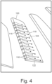
- FIG. 4 is a perspective view of blades 112 showing air flow along blades 112.
- Each of blades 112 includes leading edge 116, trailing edge 118, base 120, tip 122, pressure surface 124, suction surface 126, body 128, internal channel 130, and air outlets 132.
- Body 128 of each blade 112 is formed by leading edge 116, trailing edge 118, pressure surface 124, and suction surface 126. Trailing edge 118 is aft of leading edge 116.
- Pressure surface 124 extends from leading edge 116 to trailing edge 118, and extends radially from base 120 to tip 122.
- Suction surface 126 extends from leading edge 116 to trailing edge 118 opposite of pressure surface 124 and also extends radially from base 120 to tip 122.
- Internal channel 130 extends radially outward from base 120 within body 128, and terminates within body 128 radially inward of tip 122.
- Air outlets 132 are formed proximate to leading edge 116 and extend into body 128 to fluidically connect with internal channel 130. Air outlets 132 can be evenly spaced on leading edge 116, as shown in FIG. 3 .
- Rotor inlet air R flows through rotor disk 114 and enters internal channel 130 at base 120.
- the rotor inlet air R then flows through internal channel 130 and is discharged through air outlets 132 becoming discharged air DA. After discharging from air outlets 132, the discharged air DA then travels along body 128 and flows on pressure surface 124 and suction surface 126. The orientation of air outlets 132 can aid in directing the discharged air DA onto pressure surface 124 and suction surface 126.
- the flow of discharged air DA entrains air as integrally bladed rotor 36 rotates in fan duct 34, delaying separation from body 128 and thereby improving efficiency.
- FIG. 5 is a cross-sectional view of another embodiment of blades 112, showing air flow around body 128.
- Air outlet 132a can be formed proximate to leading edge 116 within fifteen percent of chord C on suction surface 126.
- Air outlet 132b can be formed on leading edge 116.
- Air outlet 132c can be formed proximate to leading edge 116 within fifteen percent of chord C on pressure surface 124.
- air outlets 132 can be formed only on leading edge 116 or only within fifteen percent of chord C on either pressure surface 124 or suction surface 126.
- Air outlets 132 can also be formed in any combination of leading edge 116 and within fifteen percent of chord C on pressure surface 124 or suction surface 126.
- Rotor inlet air R flows through internal channel 130 and is discharged through air outlets 132 becoming discharged air DA.
- the location of air outlets 132 can determine the direction of discharged air DA.
- Discharged air DA emerging from air outlets 132 will tend to follow an adjacent surface due to the Coanda effect.
- Discharged air DA from air outlet 132a will follow suction surface 126
- discharged air DA from air outlet 132c will follow pressure surface 124
- discharged air DA from air outlet 132b will follow pressure surface 124 and suction surface 126.
- Main flow F meets body 128 at leading edge 116 and can then flow along pressure surface 124 and suction surface 126.
- Discharged air DA follows pressure surface 124 and suction surface 126.
- main flow F When main flow F reaches pressure surface 124 and suction surface 126, main flow F will be entrained by discharged air DA.
- Main flow F being entrained by discharged air DA delays the separation of main flow F from body 128, keeping main flow F laminar for longer than main flow F would remain laminar in the absence of discharged air DA.
- Laminar flow along body 128 is more efficient than turbulent flow, and discharged air DA entraining main flow F increases the efficiency of integrally bladed rotor 36. Controlling the direction of discharged air DA via spacing and profile of air outlets 132 can change the efficiency of integrally bladed rotor 36.
- FIG. 6 is a perspective view of blades 112 showing exemplary orientations of air outlets 132.
- air outlets 132 can be irregularly spaced on leading edge 116.
- air outlets 132 can be located within fifteen percent of chord C on pressure surface 124 and suction surface 126.
- Air outlets 132 can also include circular, elliptical, and/or non-circular profiles.
- air outlets 132 can be formed from a porous foam material with pores and passages in fluidic communication with internal channel 130. The spacing, profile, and direction of air outlets 132 can be chosen to increase efficiency of an air machine through delaying the separation of air around blades 112. Blades 112 can be additive manufactured to allow for the creation of internal channel 130 and air outlets 132.
- an integrally bladed rotor for a RAM air fan includes a rotor disk and a plurality of rotor blades extending radially from the exterior rim surface of the rotor disk.
- the rotor disk includes a rim extending circumferentially about a center axis.
- the rim includes an interior rim surface and an exterior rim surface radially outward form the interior rim surface relative the central axis.
- a rotor blade of the plurality of rotor blades includes a body extending from a leading edge to a trailing edge.
- the rotor blade also includes a pressure surface formed on the body that extends from the leading edge to the trailing edge and a suction surface formed on the body opposite of the pressure surface that extends from the leading edge to the trailing edge.
- the rotor blade also includes an inner channel inside of the body of the rotor blade and extending radially within the rotor blade and a plurality of air outlets formed proximate the leading edge of the rotor blade and extending into the body to the internal channel.
- integrally bladed rotor of the preceding paragraph can optionally include, additionally and/or alternatively, any one or more of the following features, configurations and/or additional components:
- the rotor disk further includes an inlet passage formed in the rotor disk where the inlet passage extends from a side surface of the rotor disk radially between the interior rim surface and the exterior rim surface to the internal channel.
- a further embodiment of any of the foregoing integrally bladed rotors wherein the plurality of air outlets comprises a first air outlet on the leading edge and extending to the internal channel, a second air outlet on the suction surface within fifteen percent of chord from the leading edge and extending to the internal channel and a third air outlet on the pressure surface within fifteen percent of chord from the leading edge and extending to the internal channel.
- an air cycle machine comprises a fan section including the integrally bladed rotor, a turbine section including a turbine rotor, a compressor section axially between the fan section and turbine section and including a compressor rotor, a tie rod connected to the turbine rotor, the compressor rotor, and the integrally bladed rotor, at least one bearing assembly supporting the tie rod relative to a stationary structure of the air cycle machine and a bleed air passage comprising a bleed air inlet in the turbine section and a bleed air outlet in the fan section wherein the bleed air outlet is fluidically connected to the inlet passage, and wherein the bleed air passage extends across the at least one bearing assembly.
- an air cycle machine in another embodiment, includes a turbine section including a turbine rotor, a compressor section including a compressor rotor, a fan section including an integrally bladed rotor, and a tie rod connected to the turbine rotor, the compressor rotor, and the integrally bladed rotor.
- the integrally bladed rotor includes a rotor disk and a rotor blade extending radially from the exterior rim surface of the rotor disk.
- the rotor disk includes a rim extending circumferentially about a center axis.
- the rim includes an interior rim surface and an exterior rim surface radially outward from the interior rim surface relative the center axis.
- the rotor blade also includes a pressure surface formed on the body and extending from the leading edge to the trailing edge and a suction surface formed on the body opposite of the pressure surface and extending from the leading edge to the trailing edge.
- the rotor blade also includes an inner channel inside of the body of the rotor blade and extending radially within the rotor blade. A plurality of air outlets is formed proximate the leading edge of the rotor blade and extends into the body to the internal channel.
- the air cycle machine of the preceding paragraph can optionally include, additionally and/or alternatively, any one or more of the following features, configurations and/or additional components:
- a further embodiment of the foregoing air cycle machine wherein the air cycle machine includes at least one bearing assembly supporting the tie rod relative to a stationary structure of the air cycle machine.
- the air cycle machine further includes a bleed air passage with a bleed air inlet in the turbine section and a bleed air outlet in the fan section.
- the bleed air outlet is fluidically connected to the internal channel and the bleed air passage extends across the at least one bearing assembly.
- a further embodiment of any of the foregoing air cycle machines including an inlet passage formed in the rotor disk wherein the inlet passage extends from the internal channel to a side surface of the rotor disk radially between the interior rim surface and the exterior rim surface and wherein the inlet passage fluidically connects the bleed air passage to the internal channel.
- a further embodiment of any of the foregoing air cycle machines wherein the plurality of air outlets includes a first air outlet on the leading edge and extending to the internal channel; a second air outlet on the suction surface within fifteen percent of chord from the leading edge and extending to the internal channel; and a third air outlet on the pressure surface within fifteen percent of chord from the leading edge and extending to the internal channel.
- a method of manufacturing an integrally bladed rotor for a RAM air fan includes additively manufacturing at least one rotor blade.
- the at least one rotor blade includes a body having a leading edge, a trailing edge aft of the leading edge, a pressure surface extending between the leading edge and the trailing edge, and a suction surface extending between the leading edge and the trailing edge opposite the pressure surface.
- the at least one rotor blade also includes an internal channel extending radially within the body of the at least one rotor blade from the interior rim surface.
- the at least one rotor blade also includes a plurality of air outlets formed on the body proximate to the leading edge and extending into the body to fluidically connect with the internal channel.
Landscapes
- Engineering & Computer Science (AREA)
- Mechanical Engineering (AREA)
- General Engineering & Computer Science (AREA)
- Physics & Mathematics (AREA)
- Fluid Mechanics (AREA)
- Structures Of Non-Positive Displacement Pumps (AREA)
Abstract
Description
- This application is related to
U.S. Application No. 17/885,318, filed on August 10, 2022 - This invention relates to integrally bladed rotors and, more specifically, flow dynamics of integrally bladed rotors.
- An air cycle machine typically includes a fan section, a compressor section, a combustor section and a turbine section. The fan, compressor, and turbine sections include one or more circumferentially extending rows or stages of rotor blades, which may be carried on an integrally bladed rotor. Integrally bladed rotors have a rotor disk integrally joined to the rotor blades and can be used to increase aerodynamic efficiency of rotary machines. The rotor blades direct a working fluid as it moves through the rotor. As the working fluid passes over the rotor blade it can separate from laminar flow over the blade to turbulent flow near the blade. This separation and resultant turbulent flow reduces the efficiency of the overall rotary machine.
- In one aspect of the disclosure, an integrally bladed rotor for a RAM air fan includes a rotor disk and a plurality of rotor blades extending radially from the exterior rim surface of the rotor disk. The rotor disk includes a rim extending circumferentially about a center axis. The rim includes an interior rim surface and an exterior rim surface radially outward form the interior rim surface relative the central axis. A rotor blade of the plurality of rotor blades includes a body extending from a leading edge to a trailing edge. The rotor blade also includes a pressure surface formed on the body that extends from the leading edge to the trailing edge and a suction surface formed on the body opposite of the pressure surface that extends from the leading edge to the trailing edge. The rotor blade also includes an inner channel inside of the body of the rotor blade and extending radially within the rotor blade and a plurality of air outlets formed proximate the leading edge of the rotor blade and extending into the body to the internal channel.
- In another aspect of the disclosure, an air cycle machine includes a turbine section including a turbine rotor, a compressor section including a compressor rotor, a fan section including an integrally bladed rotor, and a tie rod connected to the turbine rotor, the compressor rotor, and the integrally bladed rotor. The integrally bladed rotor includes a rotor disk and a rotor blade extending radially from the exterior rim surface of the rotor disk. The rotor disk includes a rim extending circumferentially about a center axis. The rim includes an interior rim surface and an exterior rim surface radially outward from the interior rim surface relative the center axis. The rotor blade also includes a pressure surface formed on the body and extending from the leading edge to the trailing edge and a suction surface formed on the body opposite of the pressure surface and extending from the leading edge to the trailing edge. The rotor blade also includes an inner channel inside of the body of the rotor blade and extending radially within the rotor blade. A plurality of air outlets is formed proximate the leading edge of the rotor blade and extends into the body to the internal channel.
- In another aspect of the disclosure, a method of manufacturing an integrally bladed rotor for a RAM air fan is disclosed. The method includes additively manufacturing at least one rotor blade. The at least one rotor blade includes a body having a leading edge, a trailing edge aft of the leading edge, a pressure surface extending between the leading edge and the trailing edge, and a suction surface extending between the leading edge and the trailing edge opposite the pressure surface. The at least one rotor blade also includes an internal channel extending radially within the body of the at least one rotor blade from the interior rim surface. The at least one rotor blade also includes a plurality of air outlets formed on the body proximate to the leading edge and extending into the body to fluidically connect with the internal channel.
-
-
FIG. 1 is a cross-sectional view of an air cycle machine including a fan section. -
FIG. 2 is an enlarged cross-sectional view of the fan section ofFIG. 1 . -
FIG. 3 is a perspective view of a rotor blade of the fan section ofFIG. 1 with an internal channel shown in phantom and a plurality of air outlets. -
FIG. 4 is a perspective view of the rotor blade ofFIG. 3 with fluid flow exiting the plurality of air outlets and flowing along the pressure surface and the suction surface. -
FIG. 5 is a cross-sectional view of another embodiment of the rotor blade with an internal channel and air outlets proximate to a leading edge. -
FIG. 6 is a perspective view of another embodiment of the rotor blade with air outlets of varying spacing and profile. -
FIG. 1 is a cross-sectional view ofair cycle machine 10, which includesfan section 12,compressor section 14,first turbine section 16,second turbine section 18,tie rod 20, fan andcompressor housing 22,seal plate 24,first turbine housing 26, andsecond turbine housing 28.Fan section 12 includesfan inlet 30,fan duct 32,fan outlet 34, and integrally bladedrotor 36.Compressor section 14 includescompressor inlet 38, compressor outlet 40,compressor duct 42, andcompressor rotor 44.First turbine section 16 includesfirst turbine inlet 46,first turbine outlet 48,first turbine duct 50, andfirst turbine rotor 52.Second turbine section 18 includessecond turbine inlet 62, second turbine outlet 64,second turbine duct 66, andsecond turbine rotor 68.Air cycle machine 10 further includes first journal bearing 78, second journal bearing 80, compressor rotor bearing 82, first turbine rotor bearing 84, and second turbine rotor bearing 86.Air cycle machine 10 also includes fan rotor bearing 90. Also shown inFIG. 1 is axis X. - In
air cycle machine 10,fan section 12,compressor section 14,first turbine section 16, andsecond turbine section 18 are all mounted ontie rod 20.Tie rod 20 rotates about axis X. Fan andcompressor housing 22 is connected toseal plate 24 andfirst turbine housing 26 with fasteners.First turbine housing 26 is connected tosecond turbine housing 28 with fasteners. Fan and compressor housing 22, first turbine housing 26, and second turbine housing 28 together form an overall housing forair cycle machine 10. Fan and compressor housing 22houses fan section 12 andcompressor section 14. First turbine housing 26 housesfirst turbine section 16. Second turbine housing 28 housessecond turbine section 18. -
Fan section 12 includesfan inlet 30,fan duct 32,fan outlet 34, and integrally bladedrotor 36.Fan inlet 30 is connected tofan outlet 34 byfan duct 32. Integrally bladedrotor 36 is a fan rotor infan duct 32 adjacent tofan outlet 34 and is mounted to and rotates withtie rod 20. Integrally bladedrotor 36 draws air intofan section 12 to be routed throughair cycle machine 10.Fan section 12 draws in ram air from a ram air scoop or from another aircraft component like an associated gas turbine. The air drawn in enters a main flow path throughair cycle machine 10. Air moves throughfan duct 32 tofan outlet 34. -
Compressor section 14 includescompressor inlet 38, compressor outlet 40,compressor duct 42, andcompressor rotor 44.Compressor inlet 38 connects to compressor outlet 40 throughcompressor duct 42.Compressor rotor 44 is incompressor duct 42 and is mounted to and rotates withtie rod 20. Air follows the main flow path throughcompressor section 14 by enteringcompressor inlet 38.Compressor rotor 44 rotates and increases the velocity of the air. As the air moves throughcompressor duct 42 downstream ofrotor 44, air velocity decreases and air pressure increases. Air exitscompressor duct 42 through compressor outlet 40. -
First turbine section 16 includesfirst turbine inlet 46,first turbine outlet 48,first turbine duct 50, andfirst turbine rotor 52.First turbine inlet 46 connects tofirst turbine outlet 48 throughfirst turbine duct 50.First turbine rotor 52 is positioned infirst turbine duct 50 and is mounted to and rotatestie rod 20. Air follows the main flow path intofirst turbine inlet 46 and is ducted throughfirst turbine duct 50 tofirst turbine outlet 48.First turbine rotor 52 extracts energy from the air passing throughfirst turbine section 16 following the main flow path. Extracted energy rotatestie rod 20. The air expands and cools following the main flow path throughfirst turbine rotor 52. -
Second turbine section 18 includessecond turbine inlet 62, second turbine outlet 64,second turbine duct 66, andsecond turbine rotor 68.Second turbine inlet 62 connects to second turbine outlet 64 throughsecond turbine duct 66.Second turbine rotor 68 is positioned insecond turbine duct 66 and is mounted to and rotatestie rod 20. The majority of air follows the main flow path intosecond turbine inlet 62 and is ducted throughsecond turbine duct 66 to second turbine outlet 64. The remaining air enters thecooling flow tapoff 88 and becomes air bearing cooling flow BF.Second turbine rotor 68 extracts energy from the air passing throughsecond turbine section 18 and rotatestie rod 20. The air expands and cools moving throughsecond turbine rotor 68. -
Air cycle machine 10 further includes first journal bearing 78, second journal bearing 80, compressor rotor bearing 82, first turbine rotor bearing 84, and secondturbine rotor bearing 86. First journal bearing 78 is positioned infan section 12 and is supported by fan andcompressor housing 22. A radially outer surface of a first rotating shaft abuts a radially inner surface of first journal bearing 78. Second journal bearing 80 is positioned infirst turbine section 16 and is supported byfirst turbine housing 26. A radially outer surface of a second rotating shaft abuts a radially inner surface of second journal bearing 80. First journal bearing 78 and second journal bearing 80 support the first rotating shaft and the second rotating shaft, respectively. -
Compressor rotor bearing 82, first turbine rotor bearing 84, and second rotor bearing 86 are journal bearings.Compressor rotor bearing 82 has a radially inner surface abuttingcompressor rotor 44 and a radially outer surface abuttingseal plate 24. First turbine rotor bearing 84 has a radially inner surface abuttingfirst turbine rotor 52 and a radially outer surface abuttingseal plate 24. Second turbine rotor bearing 86 has a radially inner surface abuttingsecond turbine rotor 68 and a radially outer surface abutting a portion ofsecond turbine housing 28.Compressor rotor bearing 82 supportscompressor rotor 44; first turbine rotor bearing 84 supportsfirst turbine rotor 52; second turbine rotor bearing 86 supportssecond turbine rotor 68.Air cooling tapoff 88 forms an air bearing cooling flow path BF throughair cycle machine 10 with an inlet insecond turbine section 18 and an outlet infan section 12. When air fromsecond turbine section 18 entersair cooling tapoff 88 the air is directed in the air bearing cooling flow path BF across second turbine rotor bearing 86, second journal bearing 80, first turbine rotor bearing 84, compressor rotor bearing 82, first journal bearing 78, andfan rotor bearing 90 and cools those bearings. As discussed in greater detail below, a portion of the air directed through fan rotor bearing 90 will be directed into integrally bladedrotor 36. -
FIG. 2 is an enlarged cross-sectional view offan section 12 fromFIG. 1 . Integrally bladedrotor 36 includesrotor disk 114 andblades 112.Rotor disk 114 includes radially innerinterior rim surface 134 and radially outerexterior rim surface 136.Rotor disk 114 also includesinlet passage 138 extending from a side surface ofrotor disk 114 radially between radially innerinterior rim surface 134 and radially outerexterior rim surface 136.Inlet passage 138 extends tointernal channel 130, discussed below.Blades 112 are formed integral torotor disk 114. Fan rotor bearing 90 is an air bearing. Fan rotor bearing 90 includes bearinginlet hole 96, bearingduct outlet hole 98 and bearingrotor outlet hole 100..Bearing inlet hole 96 is fluidically connected to bearingduct outlet hole 98 and bearingrotor outlet hole 100 throughfan rotor bearing 90. Fan rotor bearing 90 supports integrally bladedrotor 36. - When the air flowing in
air cooling tapoff 88 reaches fan rotor bearing 90, the air enters bearinginlet hole 96 and flows throughfan rotor bearing 90. Air bearing cooling flow path BF infan section 12 separates into rotor inlet air R and cooling flow discharge air C. The cooling flow discharge air C flows through the bearingduct outlet hole 98 and is discharged intofan duct 34 where the cooling flow discharge air C reenters the main flow path. The rotor inlet air R flows through bearingrotor outlet hole 100. The rotor inlet air R then flows through integrally bladedrotor 36, as discussed below with reference toFIGS. 3 and4 . -
FIG. 3 and4 will be discussed together.FIG. 3 is a perspective view of one ofblades 112 from integrally bladedrotor 36 shown inFIG. 2 .FIG. 4 is a perspective view ofblades 112 showing air flow alongblades 112. Each ofblades 112 includesleading edge 116, trailingedge 118,base 120,tip 122,pressure surface 124,suction surface 126,body 128,internal channel 130, andair outlets 132.Body 128 of eachblade 112 is formed by leadingedge 116, trailingedge 118,pressure surface 124, andsuction surface 126. Trailingedge 118 is aft of leadingedge 116.Pressure surface 124 extends from leadingedge 116 to trailingedge 118, and extends radially frombase 120 to tip 122.Suction surface 126 extends from leadingedge 116 to trailingedge 118 opposite ofpressure surface 124 and also extends radially frombase 120 to tip 122.Internal channel 130 extends radially outward frombase 120 withinbody 128, and terminates withinbody 128 radially inward oftip 122.Air outlets 132 are formed proximate to leadingedge 116 and extend intobody 128 to fluidically connect withinternal channel 130.Air outlets 132 can be evenly spaced on leadingedge 116, as shown inFIG. 3 . Rotor inlet air R flows throughrotor disk 114 and entersinternal channel 130 atbase 120. The rotor inlet air R then flows throughinternal channel 130 and is discharged throughair outlets 132 becoming discharged air DA. After discharging fromair outlets 132, the discharged air DA then travels alongbody 128 and flows onpressure surface 124 andsuction surface 126. The orientation ofair outlets 132 can aid in directing the discharged air DA ontopressure surface 124 andsuction surface 126. The flow of discharged air DA entrains air as integrally bladedrotor 36 rotates infan duct 34, delaying separation frombody 128 and thereby improving efficiency. -
FIG. 5 is a cross-sectional view of another embodiment ofblades 112, showing air flow aroundbody 128.Air outlet 132a can be formed proximate to leadingedge 116 within fifteen percent of chord C onsuction surface 126.Air outlet 132b can be formed on leadingedge 116.Air outlet 132c can be formed proximate to leadingedge 116 within fifteen percent of chord C onpressure surface 124. In other embodiments,air outlets 132 can be formed only on leadingedge 116 or only within fifteen percent of chord C on eitherpressure surface 124 orsuction surface 126.Air outlets 132 can also be formed in any combination of leadingedge 116 and within fifteen percent of chord C onpressure surface 124 orsuction surface 126. Rotor inlet air R flows throughinternal channel 130 and is discharged throughair outlets 132 becoming discharged air DA. The location ofair outlets 132 can determine the direction of discharged air DA. Discharged air DA emerging fromair outlets 132 will tend to follow an adjacent surface due to the Coanda effect. Discharged air DA fromair outlet 132a will followsuction surface 126, discharged air DA fromair outlet 132c will followpressure surface 124, and discharged air DA fromair outlet 132b will followpressure surface 124 andsuction surface 126. Main flow F meetsbody 128 at leadingedge 116 and can then flow alongpressure surface 124 andsuction surface 126. Discharged air DA followspressure surface 124 andsuction surface 126. When main flow F reachespressure surface 124 andsuction surface 126, main flow F will be entrained by discharged air DA. Main flow F being entrained by discharged air DA delays the separation of main flow F frombody 128, keeping main flow F laminar for longer than main flow F would remain laminar in the absence of discharged air DA. Laminar flow alongbody 128 is more efficient than turbulent flow, and discharged air DA entraining main flow F increases the efficiency of integrally bladedrotor 36. Controlling the direction of discharged air DA via spacing and profile ofair outlets 132 can change the efficiency of integrally bladedrotor 36. -
FIG. 6 is a perspective view ofblades 112 showing exemplary orientations ofair outlets 132. In the embodiment ofFIG. 6 ,air outlets 132 can be irregularly spaced on leadingedge 116. In an alternate embodiment,air outlets 132 can be located within fifteen percent of chord C onpressure surface 124 andsuction surface 126.Air outlets 132 can also include circular, elliptical, and/or non-circular profiles. In an alternate embodiment,air outlets 132 can be formed from a porous foam material with pores and passages in fluidic communication withinternal channel 130. The spacing, profile, and direction ofair outlets 132 can be chosen to increase efficiency of an air machine through delaying the separation of air aroundblades 112.Blades 112 can be additive manufactured to allow for the creation ofinternal channel 130 andair outlets 132. - The following are non-exclusive descriptions of possible embodiments of the present invention.
- In one embodiment, an integrally bladed rotor for a RAM air fan includes a rotor disk and a plurality of rotor blades extending radially from the exterior rim surface of the rotor disk. The rotor disk includes a rim extending circumferentially about a center axis. The rim includes an interior rim surface and an exterior rim surface radially outward form the interior rim surface relative the central axis. A rotor blade of the plurality of rotor blades includes a body extending from a leading edge to a trailing edge. The rotor blade also includes a pressure surface formed on the body that extends from the leading edge to the trailing edge and a suction surface formed on the body opposite of the pressure surface that extends from the leading edge to the trailing edge. The rotor blade also includes an inner channel inside of the body of the rotor blade and extending radially within the rotor blade and a plurality of air outlets formed proximate the leading edge of the rotor blade and extending into the body to the internal channel.
- The integrally bladed rotor of the preceding paragraph can optionally include, additionally and/or alternatively, any one or more of the following features, configurations and/or additional components:
- A further embodiment of the foregoing integrally bladed rotor, wherein the rotor disk further includes an inlet passage formed in the rotor disk where the inlet passage extends from a side surface of the rotor disk radially between the interior rim surface and the exterior rim surface to the internal channel.
- A further embodiment of any of the foregoing integrally bladed rotors wherein at least one of the air outlets comprises a circular profile.
- A further embodiment of any of the foregoing integrally bladed rotors wherein at least one of the air outlets comprises an elliptical profile.
- A further embodiment of any of the foregoing integrally bladed rotors wherein the plurality of air outlets is evenly spaced on the leading edge.
- A further embodiment of any of the foregoing integrally bladed rotors wherein the plurality of air outlets is irregularly spaced on the leading edge.
- A further embodiment of any of the foregoing integrally bladed rotors wherein the plurality of air outlets is irregularly spaced on the leading edge.
- A further embodiment of any of the foregoing integrally bladed rotors wherein at least one air outlet of the plurality of air outlets is on the leading edge.
- A further embodiment of any of the foregoing integrally bladed rotors wherein at least one air outlet of the plurality of air outlets extends from the internal channel to the pressure surface within fifteen percent of chord from the leading edge.
- A further embodiment of any of the foregoing integrally bladed rotors wherein at least one air outlet of the plurality of air outlets extends from the internal channel to the suction surface within fifteen percent of chord from the leading edge.
- A further embodiment of any of the foregoing integrally bladed rotors wherein the plurality of air outlets comprises a first air outlet on the leading edge and extending to the internal channel, a second air outlet on the suction surface within fifteen percent of chord from the leading edge and extending to the internal channel and a third air outlet on the pressure surface within fifteen percent of chord from the leading edge and extending to the internal channel.
- A further embodiment of any of the foregoing integrally bladed rotors wherein the internal channel is of a greater diameter than each of the plurality of air outlets.
- A further embodiment of any of the foregoing integrally bladed rotors wherein an air cycle machine comprises a fan section including the integrally bladed rotor, a turbine section including a turbine rotor, a compressor section axially between the fan section and turbine section and including a compressor rotor, a tie rod connected to the turbine rotor, the compressor rotor, and the integrally bladed rotor, at least one bearing assembly supporting the tie rod relative to a stationary structure of the air cycle machine and a bleed air passage comprising a bleed air inlet in the turbine section and a bleed air outlet in the fan section wherein the bleed air outlet is fluidically connected to the inlet passage, and wherein the bleed air passage extends across the at least one bearing assembly.
- In another embodiment, an air cycle machine includes a turbine section including a turbine rotor, a compressor section including a compressor rotor, a fan section including an integrally bladed rotor, and a tie rod connected to the turbine rotor, the compressor rotor, and the integrally bladed rotor. The integrally bladed rotor includes a rotor disk and a rotor blade extending radially from the exterior rim surface of the rotor disk. The rotor disk includes a rim extending circumferentially about a center axis. The rim includes an interior rim surface and an exterior rim surface radially outward from the interior rim surface relative the center axis. The rotor blade also includes a pressure surface formed on the body and extending from the leading edge to the trailing edge and a suction surface formed on the body opposite of the pressure surface and extending from the leading edge to the trailing edge. The rotor blade also includes an inner channel inside of the body of the rotor blade and extending radially within the rotor blade. A plurality of air outlets is formed proximate the leading edge of the rotor blade and extends into the body to the internal channel.
- The air cycle machine of the preceding paragraph can optionally include, additionally and/or alternatively, any one or more of the following features, configurations and/or additional components:
- A further embodiment of the foregoing air cycle machine wherein the air cycle machine includes at least one bearing assembly supporting the tie rod relative to a stationary structure of the air cycle machine. The air cycle machine further includes a bleed air passage with a bleed air inlet in the turbine section and a bleed air outlet in the fan section. The bleed air outlet is fluidically connected to the internal channel and the bleed air passage extends across the at least one bearing assembly.
- A further embodiment of any of the foregoing air cycle machines including an inlet passage formed in the rotor disk wherein the inlet passage extends from the internal channel to a side surface of the rotor disk radially between the interior rim surface and the exterior rim surface and wherein the inlet passage fluidically connects the bleed air passage to the internal channel.
- A further embodiment of any of the foregoing air cycle machines wherein the plurality of air outlets includes a first air outlet on the leading edge and extending to the internal channel; a second air outlet on the suction surface within fifteen percent of chord from the leading edge and extending to the internal channel; and a third air outlet on the pressure surface within fifteen percent of chord from the leading edge and extending to the internal channel.
- A further embodiment of any of the foregoing air cycle machines wherein at least one air outlet of the plurality of air outlets is on the leading edge.
- A further embodiment of any of the foregoing air cycle machines wherein at least one air outlet of the plurality of air outlets extends from the internal channel to the pressure surface within fifteen percent of chord.
- A further embodiment of any of the foregoing air cycle machines wherein at least one air outlet of the plurality of air outlets extends from the internal channel to the suction surface within fifteen percent of chord from the leading edge.
- In another embodiment, a method of manufacturing an integrally bladed rotor for a RAM air fan is disclosed. The method includes additively manufacturing at least one rotor blade. The at least one rotor blade includes a body having a leading edge, a trailing edge aft of the leading edge, a pressure surface extending between the leading edge and the trailing edge, and a suction surface extending between the leading edge and the trailing edge opposite the pressure surface. The at least one rotor blade also includes an internal channel extending radially within the body of the at least one rotor blade from the interior rim surface. The at least one rotor blade also includes a plurality of air outlets formed on the body proximate to the leading edge and extending into the body to fluidically connect with the internal channel.
- While the invention has been described with reference to an exemplary embodiment(s), it will be understood by those skilled in the art that various changes may be made and equivalents may be substituted for elements thereof without departing from the scope of the invention. In addition, many modifications may be made to adapt a particular situation or material to the teachings of the invention without departing from the essential scope thereof. Therefore, it is intended that the invention not be limited to the particular embodiment(s) disclosed, but that the invention will include all embodiments falling within the scope of the appended claims.
Claims (15)
- An integrally bladed rotor (36) for a RAM air fan, the integrally bladed rotor comprising:a rotor disk (114) comprising a rim extending circumferentially about a center axis, wherein the rim comprises an interior rim surface (134) and an exterior rim surface (136) radially outward from the interior rim surface relative the center axis;a plurality of rotor blades (112) extending radially from the exterior rim surface of the integrally bladed rotor, wherein a rotor blade of the plurality of rotor blades comprises:a body (128) extending from a leading edge (116) to a trailing edge (118);a pressure surface (124) formed on the body and extending from the leading edge to the trailing edge; anda suction surface (126) formed on the body opposite of the pressure surface and extending from the leading edge to the trailing edge;an internal channel (130) inside of the body of the rotor blade and extending radially within the rotor blade; anda plurality of air outlets (132) formed proximate the leading edge of the rotor blade and extending into the body to the internal channel.
- The integrally bladed rotor of claim 1, further comprising:
an inlet passage (138) formed in the rotor disk (114), wherein the inlet passage extends from a side surface of the rotor disk radially between the interior rim surface (134) and the exterior rim surface (136) to the internal channel (130). - The integrally bladed rotor of claim 1 or 2, wherein at least one of the air outlets (132) comprises a circular profile, and/or wherein at least one of the air outlets (132) comprises an elliptical profile.
- The integrally bladed rotor of any preceding claim, wherein the plurality of air outlets (132) is evenly spaced on the leading edge (116); or wherein the plurality of air outlets (132) is irregularly spaced on the leading edge.
- The integrally bladed rotor of any preceding claim, wherein at least one air outlet of the plurality of air outlets (132) is on the leading edge.
- The integrally bladed rotor of any preceding claim 1, wherein at least one air outlet of the plurality of air outlets (132) extends from the internal channel (130) to the pressure surface (124) within fifteen percent of chord from the leading edge, and/or
wherein at least one air outlet of the plurality of air outlets extends from the internal channel (130) to the suction surface (126) within fifteen percent of chord from the leading edge. - The integrally bladed rotor of any preceding claim, wherein the plurality of air outlets (126) comprises:a first air outlet on the leading edge (116) and extending to the internal channel (130);a second air outlet on the suction surface within fifteen percent of chord from the leading edge and extending to the internal channel; anda third air outlet on the pressure surface within fifteen percent of chord from the leading edge and extending to the internal channel.
- The integrally bladed rotor of any preceding claim, wherein the internal channel (130) is of a greater diameter than each of the plurality of air outlets.
- An air cycle machine comprising the integrally bladed rotor of claim 2 or any claim dependent thereon, wherein the air cycle machine comprises:a fan section (12) comprising the integrally bladed rotor;a turbine section (16) comprising a turbine rotor;a compressor section (22) axially between the fan section the turbine section and comprising a compressor rotor;a tied rod (20) connected to the turbine rotor, the compressor rotor, and the integrally bladed rotor;at least one bearing assembly supporting the tie rod relative to a stationary structure of the air cycle machine; anda bleed air passage comprising:a bleed air inlet in the turbine section;a bleed air outlet in the fan section, wherein the bleed air outlet is fluidically connected to the inlet passage, and wherein the bleed air passage extends across the at least one bearing assembly.
- An air cycle machine comprising:a turbine section (16) comprising a turbine rotor;a compressor section (22) comprising a compressor rotor;a fan section (12) comprising an integrally bladed rotor, wherein the integrally bladed rotor comprises:a rotor disk (114) comprising a rim extending circumferentially about a center axis, wherein the rim comprises an interior rim surface (134) and an exterior rim surface (136) radially outward from the interior rim surface relative the center axis;a rotor blade (112) extending radially from the exterior rim surface of the integrally bladed rotor, wherein the rotor blade comprises:a body (128) extending from a leading edge (116) to a trailing edge (118);a pressure surface (124) formed on the body and extending from the leading edge to the trailing edge; anda suction surface (126) formed on the body opposite of the pressure surface and extending from the leading edge to the trailing edge;an internal channel (130) inside of the body of the rotor blade and extending radially within the rotor blade; anda plurality of air outlets (132) formed proximate the leading edge of the rotor blade and extending into the body to the internal channel; anda tie rod (20) connected to the turbine rotor, the compressor rotor, and the integrally bladed rotor.
- The air cycle machine of claim 10, further comprising:at least one bearing assembly supporting the tie rod (20) relative to a stationary structure of the air cycle machine; anda bleed air passage comprising:a bleed air inlet in the turbine section;a bleed air outlet in the fan section, wherein the bleed air outlet is fluidically connected to the internal channel, and wherein the bleed air passage extends across the at least one bearing assembly.
- The air cycle machine of claim 11, further comprising:
an inlet passage formed in the rotor disk (114), wherein the inlet passage extends from the internal channel to a side surface of the rotor disk radially between the interior rim surface and the exterior rim surface, and wherein the inlet passage fluidically connects the bleed air passage to the internal channel. - The air cycle machine of claim 12, wherein the plurality of air outlets (132) comprises:a first air outlet on the leading edge (116) and extending to the internal channel;a second air outlet on the suction surface within fifteen percent of chord from the leading edge and extending to the internal channel; anda third air outlet on the pressure surface within fifteen percent of chord from the leading edge and extending to the internal channel.
- The air cycle machine of claim 12, wherein at least one air outlet of the plurality of air outlets (132) is on the leading edge (116); and/orwherein at least one air outlet of the plurality of air outlets extends from the internal channel to the pressure surface within fifteen percent of chord from the leading edge; and/orwherein at least one air outlet of the plurality of air outlets extends from the internal channel to the suction surface within fifteen percent of chord from the leading edge.
- A method of manufacturing an integrally bladed rotor for a RAM air fan, the method comprising:
additively manufacturing at least one rotor blade, the at least one rotor blade comprising:a body having a leading edge, a trailing edge aft of the leading edge, a pressure surface extending between the leading edge and the trailing edge, and a suction surface extending between the leading edge and the trailing edge opposite the pressure surface; andan internal channel extending radially within the body of the at least one rotor blade from the interior rim surface; anda plurality of air outlets formed on the body of the at least one rotor blade proximate to the leading edge and extending into the body to fluidically connect with the internal channel.
Applications Claiming Priority (1)
| Application Number | Priority Date | Filing Date | Title |
|---|---|---|---|
| US17/885,318 US11898458B1 (en) | 2022-08-10 | 2022-08-10 | Radial fan with leading edge air injection |
Publications (2)
| Publication Number | Publication Date |
|---|---|
| EP4321730A1 true EP4321730A1 (en) | 2024-02-14 |
| EP4321730B1 EP4321730B1 (en) | 2026-03-04 |
Family
ID=87556300
Family Applications (1)
| Application Number | Title | Priority Date | Filing Date |
|---|---|---|---|
| EP23189402.3A Active EP4321730B1 (en) | 2022-08-10 | 2023-08-03 | Air cycle machine |
Country Status (2)
| Country | Link |
|---|---|
| US (1) | US11898458B1 (en) |
| EP (1) | EP4321730B1 (en) |
Citations (3)
| Publication number | Priority date | Publication date | Assignee | Title |
|---|---|---|---|---|
| US3883268A (en) * | 1971-11-01 | 1975-05-13 | Gen Electric | Blunted leading edge fan blade for noise reduction |
| US20170108031A1 (en) * | 2015-10-14 | 2017-04-20 | Hamilton Sundstrand Corporation | Turbine thrust shaft for air bearing cooling |
| US20200332658A1 (en) * | 2019-04-18 | 2020-10-22 | Pratt & Whitney Canada Corp. | Fan blade ice protection using hot air |
Family Cites Families (26)
| Publication number | Priority date | Publication date | Assignee | Title |
|---|---|---|---|---|
| US4807433A (en) | 1983-05-05 | 1989-02-28 | General Electric Company | Turbine cooling air modulation |
| US5113670A (en) * | 1990-08-03 | 1992-05-19 | United Technologies Corporation | Bearing cooling arrangement for air cycle machine |
| US5156526A (en) * | 1990-12-18 | 1992-10-20 | General Electric Company | Rotation enhanced rotor blade cooling using a single row of coolant passageways |
| US5165852A (en) * | 1990-12-18 | 1992-11-24 | General Electric Company | Rotation enhanced rotor blade cooling using a double row of coolant passageways |
| US6223524B1 (en) * | 1998-01-23 | 2001-05-01 | Diversitech, Inc. | Shrouds for gas turbine engines and methods for making the same |
| US6224327B1 (en) * | 1998-02-17 | 2001-05-01 | Mitsubishi Heavy Idustries, Ltd. | Steam-cooling type gas turbine |
| JP3361501B2 (en) * | 2000-03-02 | 2003-01-07 | 株式会社日立製作所 | Closed-circuit blade cooling turbine |
| JP3762661B2 (en) * | 2001-05-31 | 2006-04-05 | 株式会社日立製作所 | Turbine rotor |
| GB2411441B (en) * | 2004-02-24 | 2006-04-19 | Rolls Royce Plc | Fan or compressor blisk |
| US7186085B2 (en) * | 2004-11-18 | 2007-03-06 | General Electric Company | Multiform film cooling holes |
| US8007237B2 (en) * | 2006-12-29 | 2011-08-30 | Pratt & Whitney Canada Corp. | Cooled airfoil component |
| US7661931B1 (en) * | 2007-02-20 | 2010-02-16 | Florida Turbine Technologies, Inc. | Bladed rotor with shear pin attachment |
| US8079802B2 (en) * | 2008-06-30 | 2011-12-20 | Mitsubishi Heavy Industries, Ltd. | Gas turbine |
| US9228440B2 (en) * | 2012-12-03 | 2016-01-05 | Honeywell International Inc. | Turbine blade airfoils including showerhead film cooling systems, and methods for forming an improved showerhead film cooled airfoil of a turbine blade |
| US9377052B2 (en) * | 2014-11-13 | 2016-06-28 | Hamilton Sundstrand Corporation | Air cycle machine with bearing failure detection |
| US9878793B2 (en) * | 2015-01-16 | 2018-01-30 | Hamilton Sundstrand Corporation | Cooling air supply control system for air cycle machine |
| US20170102002A1 (en) * | 2015-10-12 | 2017-04-13 | Hamilton Sunstrand Corporation | Fan shaft for air cycle machine |
| US10107109B2 (en) | 2015-12-10 | 2018-10-23 | United Technologies Corporation | Gas turbine engine component cooling assembly |
| US10514065B2 (en) * | 2015-12-14 | 2019-12-24 | Hamilton Sundstrand Corporation | Bearing thermal management system and method |
| US9784126B2 (en) * | 2015-12-14 | 2017-10-10 | Hamilton Sundstrand Corporation | Variable-sized cooling air flow path |
| US10787931B2 (en) * | 2017-05-25 | 2020-09-29 | General Electric Company | Method and structure of interdigitated turbine engine thermal management |
| US10718265B2 (en) * | 2017-05-25 | 2020-07-21 | General Electric Company | Interdigitated turbine engine air bearing and method of operation |
| US10935037B2 (en) * | 2018-01-05 | 2021-03-02 | Raytheon Technologies Corporation | Tool for simultaneous local stress relief of each of a multiple of linear friction welds of a rotor forging |
| US11001389B2 (en) * | 2018-11-29 | 2021-05-11 | General Electric Company | Propulsion engine thermal management system |
| US11002146B1 (en) * | 2020-10-26 | 2021-05-11 | Antheon Research, Inc. | Power generation system |
| US11530617B2 (en) * | 2020-10-26 | 2022-12-20 | Antheon Research, Inc. | Gas turbine propulsion system |
-
2022
- 2022-08-10 US US17/885,318 patent/US11898458B1/en active Active
-
2023
- 2023-08-03 EP EP23189402.3A patent/EP4321730B1/en active Active
Patent Citations (3)
| Publication number | Priority date | Publication date | Assignee | Title |
|---|---|---|---|---|
| US3883268A (en) * | 1971-11-01 | 1975-05-13 | Gen Electric | Blunted leading edge fan blade for noise reduction |
| US20170108031A1 (en) * | 2015-10-14 | 2017-04-20 | Hamilton Sundstrand Corporation | Turbine thrust shaft for air bearing cooling |
| US20200332658A1 (en) * | 2019-04-18 | 2020-10-22 | Pratt & Whitney Canada Corp. | Fan blade ice protection using hot air |
Also Published As
| Publication number | Publication date |
|---|---|
| EP4321730B1 (en) | 2026-03-04 |
| US20240052745A1 (en) | 2024-02-15 |
| US11898458B1 (en) | 2024-02-13 |
Similar Documents
| Publication | Publication Date | Title |
|---|---|---|
| US9976568B2 (en) | Air cycle machine compressor diffuser | |
| EP1624169B1 (en) | Fan assembly for a gas turbine | |
| US10577955B2 (en) | Airfoil assembly with a scalloped flow surface | |
| JP3977797B2 (en) | Combustor inlet diffuser with boundary layer blowing | |
| JP4152184B2 (en) | Turbine platform with descending stage | |
| JP5948436B2 (en) | Blade cooling circuit | |
| EP1329615B1 (en) | Compressor stator bleed system | |
| US20230130213A1 (en) | Turbine engine with airfoil having high acceleration and low blade turning | |
| JP2008019856A (en) | Fan blade and turbofan engine assembly | |
| CN108979737B (en) | Engine component with insert and method of separating dust therein | |
| CN107084004B (en) | Impact holes for turbine engine components | |
| US11933193B2 (en) | Turbine engine with an airfoil having a set of dimples | |
| EP1421257B1 (en) | Double flow compressor | |
| US11585347B2 (en) | Mixed-flow compressor configuration for a refrigeration system | |
| EP3608506B1 (en) | Gas turbine vane comprising a trunion with cooling channels | |
| US20160312618A1 (en) | Rotor assembly with scoop | |
| US20160312641A1 (en) | Rotor assembly with wear member | |
| EP3647544B1 (en) | Cooled gas turbine guide vane airfoil | |
| US11898458B1 (en) | Radial fan with leading edge air injection | |
| US20180142569A1 (en) | Inlet guide wheel for a turbo engine | |
| US20220186746A1 (en) | Centrifugal or mixed-flow compressor including aspirated diffuser | |
| EP3660272B1 (en) | Inter-compressor flow divider profiling | |
| EP4321759B1 (en) | Radial compressor with leading edge air injection | |
| US20230243262A1 (en) | Rotor with inlets to channels |
Legal Events
| Date | Code | Title | Description |
|---|---|---|---|
| PUAI | Public reference made under article 153(3) epc to a published international application that has entered the european phase |
Free format text: ORIGINAL CODE: 0009012 |
|
| STAA | Information on the status of an ep patent application or granted ep patent |
Free format text: STATUS: THE APPLICATION HAS BEEN PUBLISHED |
|
| AK | Designated contracting states |
Kind code of ref document: A1 Designated state(s): AL AT BE BG CH CY CZ DE DK EE ES FI FR GB GR HR HU IE IS IT LI LT LU LV MC ME MK MT NL NO PL PT RO RS SE SI SK SM TR |
|
| STAA | Information on the status of an ep patent application or granted ep patent |
Free format text: STATUS: REQUEST FOR EXAMINATION WAS MADE |
|
| 17P | Request for examination filed |
Effective date: 20240809 |
|
| RBV | Designated contracting states (corrected) |
Designated state(s): AL AT BE BG CH CY CZ DE DK EE ES FI FR GB GR HR HU IE IS IT LI LT LU LV MC ME MK MT NL NO PL PT RO RS SE SI SK SM TR |
|
| GRAP | Despatch of communication of intention to grant a patent |
Free format text: ORIGINAL CODE: EPIDOSNIGR1 |
|
| STAA | Information on the status of an ep patent application or granted ep patent |
Free format text: STATUS: GRANT OF PATENT IS INTENDED |
|
| INTG | Intention to grant announced |
Effective date: 20250923 |
|
| GRAS | Grant fee paid |
Free format text: ORIGINAL CODE: EPIDOSNIGR3 |
|
| GRAA | (expected) grant |
Free format text: ORIGINAL CODE: 0009210 |
|
| STAA | Information on the status of an ep patent application or granted ep patent |
Free format text: STATUS: THE PATENT HAS BEEN GRANTED |
|
| AK | Designated contracting states |
Kind code of ref document: B1 Designated state(s): AL AT BE BG CH CY CZ DE DK EE ES FI FR GB GR HR HU IE IS IT LI LT LU LV MC ME MK MT NL NO PL PT RO RS SE SI SK SM TR |
|
| REG | Reference to a national code |
Ref country code: CH Ref legal event code: F10 Free format text: ST27 STATUS EVENT CODE: U-0-0-F10-F00 (AS PROVIDED BY THE NATIONAL OFFICE) Effective date: 20260304 Ref country code: GB Ref legal event code: FG4D |
|
| REG | Reference to a national code |
Ref country code: IE Ref legal event code: FG4D |
|
| REG | Reference to a national code |
Ref country code: DE Ref legal event code: R096 Ref document number: 602023012884 Country of ref document: DE |
|
| PG25 | Lapsed in a contracting state [announced via postgrant information from national office to epo] |
Ref country code: RS Free format text: LAPSE BECAUSE OF FAILURE TO SUBMIT A TRANSLATION OF THE DESCRIPTION OR TO PAY THE FEE WITHIN THE PRESCRIBED TIME-LIMIT Effective date: 20260604 |
|
| PG25 | Lapsed in a contracting state [announced via postgrant information from national office to epo] |
Ref country code: ES Free format text: LAPSE BECAUSE OF FAILURE TO SUBMIT A TRANSLATION OF THE DESCRIPTION OR TO PAY THE FEE WITHIN THE PRESCRIBED TIME-LIMIT Effective date: 20260304 |
|
| REG | Reference to a national code |
Ref country code: NL Ref legal event code: MP Effective date: 20260304 |
|
| PG25 | Lapsed in a contracting state [announced via postgrant information from national office to epo] |
Ref country code: PL Free format text: LAPSE BECAUSE OF FAILURE TO SUBMIT A TRANSLATION OF THE DESCRIPTION OR TO PAY THE FEE WITHIN THE PRESCRIBED TIME-LIMIT Effective date: 20260304 |
|
| PG25 | Lapsed in a contracting state [announced via postgrant information from national office to epo] |
Ref country code: GR Free format text: LAPSE BECAUSE OF FAILURE TO SUBMIT A TRANSLATION OF THE DESCRIPTION OR TO PAY THE FEE WITHIN THE PRESCRIBED TIME-LIMIT Effective date: 20260605 |
|
| REG | Reference to a national code |
Ref country code: LT Ref legal event code: MG9D |
|
| PG25 | Lapsed in a contracting state [announced via postgrant information from national office to epo] |
Ref country code: LT Free format text: LAPSE BECAUSE OF FAILURE TO SUBMIT A TRANSLATION OF THE DESCRIPTION OR TO PAY THE FEE WITHIN THE PRESCRIBED TIME-LIMIT Effective date: 20260304 |
|
| PG25 | Lapsed in a contracting state [announced via postgrant information from national office to epo] |
Ref country code: NO Free format text: LAPSE BECAUSE OF FAILURE TO SUBMIT A TRANSLATION OF THE DESCRIPTION OR TO PAY THE FEE WITHIN THE PRESCRIBED TIME-LIMIT Effective date: 20260604 |
|
| PG25 | Lapsed in a contracting state [announced via postgrant information from national office to epo] |
Ref country code: SE Free format text: LAPSE BECAUSE OF FAILURE TO SUBMIT A TRANSLATION OF THE DESCRIPTION OR TO PAY THE FEE WITHIN THE PRESCRIBED TIME-LIMIT Effective date: 20260304 Ref country code: FI Free format text: LAPSE BECAUSE OF FAILURE TO SUBMIT A TRANSLATION OF THE DESCRIPTION OR TO PAY THE FEE WITHIN THE PRESCRIBED TIME-LIMIT Effective date: 20260304 |
|
| PG25 | Lapsed in a contracting state [announced via postgrant information from national office to epo] |
Ref country code: HR Free format text: LAPSE BECAUSE OF FAILURE TO SUBMIT A TRANSLATION OF THE DESCRIPTION OR TO PAY THE FEE WITHIN THE PRESCRIBED TIME-LIMIT Effective date: 20260304 |
|
| PG25 | Lapsed in a contracting state [announced via postgrant information from national office to epo] |
Ref country code: LV Free format text: LAPSE BECAUSE OF FAILURE TO SUBMIT A TRANSLATION OF THE DESCRIPTION OR TO PAY THE FEE WITHIN THE PRESCRIBED TIME-LIMIT Effective date: 20260304 |
|
| PG25 | Lapsed in a contracting state [announced via postgrant information from national office to epo] |
Ref country code: BG Free format text: LAPSE BECAUSE OF FAILURE TO SUBMIT A TRANSLATION OF THE DESCRIPTION OR TO PAY THE FEE WITHIN THE PRESCRIBED TIME-LIMIT Effective date: 20260304 |