EP4321692A1 - Work machine and work machine system - Google Patents
Work machine and work machine system Download PDFInfo
- Publication number
- EP4321692A1 EP4321692A1 EP22784451.1A EP22784451A EP4321692A1 EP 4321692 A1 EP4321692 A1 EP 4321692A1 EP 22784451 A EP22784451 A EP 22784451A EP 4321692 A1 EP4321692 A1 EP 4321692A1
- Authority
- EP
- European Patent Office
- Prior art keywords
- section
- instruction
- work machine
- move
- control instruction
- Prior art date
- Legal status (The legal status is an assumption and is not a legal conclusion. Google has not performed a legal analysis and makes no representation as to the accuracy of the status listed.)
- Granted
Links
Images


Classifications
-
- E—FIXED CONSTRUCTIONS
- E02—HYDRAULIC ENGINEERING; FOUNDATIONS; SOIL SHIFTING
- E02F—DREDGING; SOIL-SHIFTING
- E02F9/00—Component parts of dredgers or soil-shifting machines, not restricted to one of the kinds covered by groups E02F3/00 - E02F7/00
- E02F9/20—Drives; Control devices
- E02F9/2025—Particular purposes of control systems not otherwise provided for
- E02F9/2033—Limiting the movement of frames or implements, e.g. to avoid collision between implements and the cabin
-
- E—FIXED CONSTRUCTIONS
- E02—HYDRAULIC ENGINEERING; FOUNDATIONS; SOIL SHIFTING
- E02F—DREDGING; SOIL-SHIFTING
- E02F9/00—Component parts of dredgers or soil-shifting machines, not restricted to one of the kinds covered by groups E02F3/00 - E02F7/00
- E02F9/20—Drives; Control devices
- E02F9/2025—Particular purposes of control systems not otherwise provided for
-
- E—FIXED CONSTRUCTIONS
- E02—HYDRAULIC ENGINEERING; FOUNDATIONS; SOIL SHIFTING
- E02F—DREDGING; SOIL-SHIFTING
- E02F9/00—Component parts of dredgers or soil-shifting machines, not restricted to one of the kinds covered by groups E02F3/00 - E02F7/00
- E02F9/20—Drives; Control devices
- E02F9/2025—Particular purposes of control systems not otherwise provided for
- E02F9/205—Remotely operated machines, e.g. unmanned vehicles
-
- E—FIXED CONSTRUCTIONS
- E02—HYDRAULIC ENGINEERING; FOUNDATIONS; SOIL SHIFTING
- E02F—DREDGING; SOIL-SHIFTING
- E02F9/00—Component parts of dredgers or soil-shifting machines, not restricted to one of the kinds covered by groups E02F3/00 - E02F7/00
- E02F9/24—Safety devices, e.g. for preventing overload
-
- E—FIXED CONSTRUCTIONS
- E02—HYDRAULIC ENGINEERING; FOUNDATIONS; SOIL SHIFTING
- E02F—DREDGING; SOIL-SHIFTING
- E02F9/00—Component parts of dredgers or soil-shifting machines, not restricted to one of the kinds covered by groups E02F3/00 - E02F7/00
- E02F9/26—Indicating devices
-
- E—FIXED CONSTRUCTIONS
- E02—HYDRAULIC ENGINEERING; FOUNDATIONS; SOIL SHIFTING
- E02F—DREDGING; SOIL-SHIFTING
- E02F9/00—Component parts of dredgers or soil-shifting machines, not restricted to one of the kinds covered by groups E02F3/00 - E02F7/00
- E02F9/26—Indicating devices
- E02F9/261—Surveying the work-site to be treated
- E02F9/262—Surveying the work-site to be treated with follow-up actions to control the work tool, e.g. controller
-
- E—FIXED CONSTRUCTIONS
- E02—HYDRAULIC ENGINEERING; FOUNDATIONS; SOIL SHIFTING
- E02F—DREDGING; SOIL-SHIFTING
- E02F9/00—Component parts of dredgers or soil-shifting machines, not restricted to one of the kinds covered by groups E02F3/00 - E02F7/00
- E02F9/26—Indicating devices
- E02F9/267—Diagnosing or detecting failure of vehicles
- E02F9/268—Diagnosing or detecting failure of vehicles with failure correction follow-up actions
-
- B—PERFORMING OPERATIONS; TRANSPORTING
- B60—VEHICLES IN GENERAL
- B60Y—INDEXING SCHEME RELATING TO ASPECTS CROSS-CUTTING VEHICLE TECHNOLOGY
- B60Y2200/00—Type of vehicle
- B60Y2200/40—Special vehicles
- B60Y2200/41—Construction vehicles, e.g. graders, excavators
- B60Y2200/412—Excavators
-
- E—FIXED CONSTRUCTIONS
- E02—HYDRAULIC ENGINEERING; FOUNDATIONS; SOIL SHIFTING
- E02F—DREDGING; SOIL-SHIFTING
- E02F3/00—Dredgers; Soil-shifting machines
- E02F3/04—Dredgers; Soil-shifting machines mechanically-driven
- E02F3/28—Dredgers; Soil-shifting machines mechanically-driven with digging tools mounted on a dipper- or bucket-arm, i.e. there is either one arm or a pair of arms, e.g. dippers, buckets
- E02F3/36—Component parts
- E02F3/42—Drives for dippers, buckets, dipper-arms or bucket-arms
- E02F3/43—Control of dipper or bucket position; Control of sequence of drive operations
- E02F3/435—Control of dipper or bucket position; Control of sequence of drive operations for dipper-arms, backhoes or the like
Definitions
- the present invention relates to a work machine and a work machine system.
- Patent Literature 1 describes "a work vehicle comprises: an imaging device for capturing an image showing a work object; an image transmission section for transmitting the image captured by the imaging device to a control device; an operation signal receiving section for receiving an operation signal from the control device; and a movement control section for restricting the operation signal in response to transmission situation of the image".
- Patent Literature 2 describes "a loading equipment control device for controlling loading equipment comprising a rotary body rotating around a rotation center and a work machine including a bucket and mounted to the rotary body, wherein the load equipment control device comprises: a loaded machine information obtaining section for obtaining position information and direction information of a loaded machine; soil removal position identification section for identifying a soil removal position wherein soil is loaded to the loaded machine based on the position information and the direction information; a bucket position identification section for identifying a position of the bucket when a soil removal signal for moving the bucket to the soil removal position is inputted; and an operation signal generation section for generating an operation signal for moving the bucket from the identified position to the soil removal position.
- Patent Literature 1 describes a mechanism for restricting the operation signal under a situation wherein abnormality arises in image transmission and the operator cannot operate the work machine appropriately.
- Patent Literature 2 describes a mechanism for avoiding coming into contact with a hauling vehicle without any operation of an operator by identifying a vehicle position, a direction and a soil removal position.
- an object of the present invention is to reduce a risk of coming into contact with an obstacle nearby even if the vehicle body does not stop immediately due to inertia in a case wherein abnormality arises in a work machine.
- the present description includes the disclosure of Japanese Patent Application No. 2021-066428 , which is the basis of the priority of the present application.
- the risk that the vehicle body comes into contact with an obstacle nearby is reduced in a case wherein abnormality arises in a work machine.
- An target of the present example is vehicle body control when abnormality arises in remote control of a shovel (work machine) such as shown in Fig. 1 .
- the shovel comprises: a rotary body 202 including a cab 201; a traveling body 206; and a work machinery 309 including a boom 203, an arm 204 and a bucket 205.
- the rotary body 202 is rotatably mounted onto the traveling body 206.
- the work machinery 309 is mounted to the rotary body 202, includes the boom 203, the arm 204 and a work tool, and is constructed to be an articulated type.
- the work tool is the bucket 205 in this example, but this may be a hydraulics breaker / chisel, a crusher, a steel framed reinforced concrete dismantler, a reinforcing steel cutter, a fork, a fork grapple, a mounted hydraulic auger, a grass cutter, a bucket hammer, a magnet, etc.
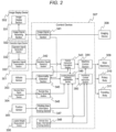
- Fig. 2 is a system block diagram of the present example.
- the work machine (for example, a shovel) comprises a control device 307, an imaging device 308, the work machinery 309, a rotary body 310 and a traveling body 311. Also, the work machine comprises an attitude sensor 303, a position sensor 305 and a loaded weight measurement device 306.
- the work machine system related to the present example comprises: the above work machine; an operation input device 301 provided outside the work machine; an image display device 302; and a remote stop signal transmission device 304. They output signals to the control device 307.
- the remote stop signal transmission device 304 is a device for transmitting an emergency stop signal that instructs emergency stop of the work machine and is used, for example, by a worker nearby the work machine in order to avoid an accident by the work machine.
- the operation input device 301 may be a portion of the work machine or located outside the work machine. If it is located outside the work machine, the operation input device 301 receives an input from a remote operator.
- the operation input device 301 comprises an operation signal generation section 332 for generating an operation signal in response to an operation of an operator and an operation signal transmission section 333 for transmitting the operation signal to the work machine.
- the work machine comprises an imaging device 308 for capturing an image around the work machine.
- the control device 307 comprises an operation signal receiving section 342 and an image signal transmission section 341.
- the operation signal receiving section 342 receives the operation signal transmitted by the operation signal transmission section 333 and outputs this to the control instruction calculation section 343.
- the image signal transmission section 341 transmits the image signal outputted by the imaging device 308 to an outside of the work machine (in this example, to the image display device 302).
- the image display device 302 comprises an image signal receiving section 322 for receiving the image signal transmitted by the image signal transmission section 341 and an image display section 331 for outputting an image to the operator.
- the operator of the shovel confirms a situation around the shovel by the image captured by the imaging device 308 and outputted by the image display device 302. Also, the operator operates the work machinery 309, the rotary body 310 and the traveling body 311 from remote via the operation input device 301.
- the image captured by the imaging device 308 is transmitted from the image signal transmission section 341 of the control device 307 to the outside of the vehicle and received by the image signal receiving section 322 of the image display device 302.
- the received image signal is outputted to the operator via the image display section 331.
- the operation input device 301 has an operation lever. If the operator operates the lever, the operation signal generation section 332 outputs an operated angle of the lever as the operation signal.
- the operation signal is transmitted to the shovel via the operation signal transmission section 333 and received by the operation signal receiving section 342 of the shovel.
- the operation signal is transformed into an operation control instruction such as an instructed pressure by the control instruction calculation section 343.
- the control instruction calculation section 343 calculates the operation control instructions to the rotary body 310, the traveling body 311 and the work machinery 309 in response to the operation instruction outputted from the operation input device 301.
- the control instruction calculation section 343 also modifies the operation control instruction so as to stop movement toward a position of a preset specific obstacle based on a vehicle attitude sensed by the attitude sensor 303 as well as the operation signal.
- the position of the specific obstacle may be stored, for example, in a storage means of the control device 307.
- the specific obstacle herein is, for example, a footing for loading soil to a dump car. If the operator operates the work machinery without noticing the footing, the control instruction calculation section 343 determines whether the work machinery 309, the rotary body 310 or the traveling body 311 comes into contact with the footing if it is controlled according to the operation. If it is determined that it comes into contact, the control instruction calculation section 343 does not perform the control according to the operation (i.e.
- the control instruction calculation section 343 calculates an operation control instruction in response to attitude information detected by the attitude sensor 303. For example, it determines whether a specific operation may be performed in response to the attitude of the work machine, and outputs or stops the operation control instruction in response to the result.
- the machine control section 344 controls the work machinery 309, the rotary body 310 and the traveling body 311 in response to the operation control instruction of the control instruction calculation section 343.
- An abnormality detection section 345 detects abnormality of a signal from outside the work machine or abnormality of the work machine.
- a process of the present example is shown in the flowchart of Fig. 3 .
- the present example is explained according to the flowchart.
- the process shown in this flowchart is performed, for example, by the control device 307.
- the abnormality detection section 345 detects the abnormality of a signal from outside or the abnormality of the work machine.
- Step 401 it is determined whether there is abnormality in communication of the operation signal.
- the abnormality herein includes, communication breakdown, communication delay equal to or longer than a predetermined time, a bit error in the operation signal, abnormality of acknowledgment, etc., between the operation signal transmission section 333 and the operation signal receiving section 342.
- the abnormality detection section 345 detects communication delay, communication breakdown or loss of communication data arisen between the operation signal transmission section 333 and the operation signal receiving section 324 as the abnormality. If it is determined that there is abnormality, the process proceeds to Step 405. If it is determined that there is no abnormality, the process proceeds to Step 402.
- Step 402 it is determined whether there is abnormality in communication of the image signal.
- the abnormality herein includes, communication breakdown, communication delay equal to or longer than a predetermined time, a bit error in the image signal, abnormality of acknowledgment, etc., between the image signal transmission section 341 and the image signal receiving section 322.
- the abnormality detection section 345 detects communication delay, communication breakdown or loss of communication data arisen between the image signal transmission section 341 and the image signal receiving section 322 as the abnormality. If it is determined that there is abnormality, the process proceeds to Step 405. If it is determined that there is no abnormality, the process proceeds to Step 403.
- Abnormality in communication of the operation signal or the image signal can be detected appropriately by such abnormality detection criteria.
- Step 403 it is determined whether there is abnormality in the attitude sensor 303.
- the work machine comprises the attitude sensor 303.
- the attitude sensor 303 detects attitude information representing attitude of the work machine.
- the attitude sensor includes, for example, a potentiometer of a variable resistor type and an IMU (Inertial Measurement Unit). If it is determined that there is abnormality, the process proceeds to Step 405. If it is determined that there is no abnormality, the process proceeds to Step 404.
- the control instruction calculation section 343 calculates the operation control instruction in response to the attitude information detected by the attitude sensor 303. For example, it determines whether a specific operation may be performed in response to the attitude of the work machine, and outputs or stops the operation control instruction in response to the result.
- the abnormality detection section 345 detects signal loss or precision deterioration of the attitude sensor 303 as abnormality. Also, if the sensor output is an analog signal, the abnormality of the attitude sensor 303 may be breaking of wire or deviation from a predetermined signal level. If the sensor output is a digital signal, the abnormality of the attitude sensor 303 may be communication breakdown, deviation from predetermined communication content, receiving of a signal indicating internal abnormality, etc. Abnormality of the attitude sensor 303 can be detected appropriately by such detection criteria.
- Step 404 the remote stop signal receiving section 346 determines whether an emergency stop signal is received.
- the remote stop signal receiving section 346 can receive the emergency stop signal.
- the emergency stop signal is transmitted and received, for example, as a remote signal. If it is determined that there is abnormality, the process proceeds to Step 405. If it is determined that there is no abnormality, the process is terminated.
- an avoiding movement necessity determination section 349 distinguishes movement situation of the traveling body 311, the rotary body 310 and the work machinery 309 and determines whether avoiding movement is necessary (Steps 405 and 406 explained later).
- the avoiding movement necessity determination section 349 determines that an avoiding movement is necessary if: an instruction to move to rotate the rotary body 310, an instruction to move to travel the traveling body 311, or an instruction to move the boom 203 in a downward direction is being outputted from the control instruction calculation section 343; or the time period after an instruction to move to rotate the rotary body 310, an instruction to move to travel the traveling body 311, or an instruction to move the boom 203 in a downward direction is last outputted and before the abnormality detection section 345 detects the abnormality is equal to or less than a first time period.
- an avoidance control instruction includes an instruction to move the boom 203 in an upward direction (for example, during a predetermined time period).
- Step 405 the avoiding movement necessity determination section 349 determines whether there is movement of the rotary body 310, whether there is movement of the traveling body 311 or whether there is movement of the boom 203 in a downward direction. If it is determined that there is any of the movements, the process proceeds to Step 406. If it is determined that there is not any of the movements, the process is terminated.
- Step 406 it may be determined whether there is a construct and/or an obstacle above the work machine. If there is the construct and/or the obstacle, the process proceeds to Step 407. If there is no construct and/or obstacle, the process is terminated.
- Step 407 that is, in a case wherein it is determined by the avoiding movement necessity determination section 349 that the avoiding movement is necessary, the avoidance control instruction section 350 calculates an avoidance control instruction and outputs this to the machine control section 344.
- the emergency stop signal may be processed in a similar manner.
- the avoiding movement necessity determination section 349 determines that an avoiding movement is necessary if: an instruction to move to rotate the rotary body 310, an instruction to move to travel the traveling body 311, or an instruction to move the boom 203 in a downward direction is being outputted from the control instruction calculation section 343; or the time period after an instruction to move the rotary body 310, an instruction to move the traveling body 311, or an instruction to move the boom 203 in a downward direction is last outputted and before the remote stop signal receiving section 346 receives the emergency stop signal is equal to or less than a first time period.
- an avoidance control instruction includes an instruction to move the boom 203 in an upward direction (for example, during a predetermined time period).
- Such determination criteria enables appropriate determination considering a free running time (for example, the time period after an instruction to move the boom 203 is outputted and before it is determined that the avoiding movement is necessary). In particular, considering the elapsed time after it is last outputted, it can be determined appropriately whether the avoiding movement is necessary even in a modified example wherein the sensor for detecting a situation of the work machine is not provided.
- a free running time for example, the time period after an instruction to move the boom 203 is outputted and before it is determined that the avoiding movement is necessary.
- Step 405 the avoiding movement necessity determination section 349 determines whether there is movement of the rotary body 310, whether there is movement of the traveling body 311 and whether there is movement of the boom 203 in a downward direction. All of them are movement that raises risk that the work machinery 309 comes into contact with an obstacle around the vehicle body.
- Steps 401-404 the time instant of abnormality detection or the time instant of receiving the emergency stop signal is denoted as time instant t1.
- time instant t1 the time instant of abnormality detection or the time instant of receiving the emergency stop signal.
- Free running time wherein the movement continues may occur after the operation control instruction is stopped. Accordingly, if dt1 is shorter than a predetermined time period (first time period), it is determined that the avoiding movement is necessary.
- the free running time after the operation control instruction is stopped is long. Accordingly, it may be designed so that it is determined that the avoiding movement is necessary if dt1 is shorter than a predetermined time period (second time period) corresponding to a vehicle size class of the work machine and/or a weight of the load held in the vehicle size class information holding section 348 ( Fig. 2 ).
- the control device 307 may comprise the vehicle size class information holding section 348 that holds vehicle size class information of the work machine.
- the work machine may comprise the loaded weight measurement device 306 for detecting the loaded weight of the load that is loaded into the work machine.
- the avoiding movement necessity determination section 349 determines that the avoiding movement is necessary if: an instruction to move the rotary body 310 or an instruction to move the boom 203 in a downward direction is being outputted from the control instruction calculation section 343; or the time period after an instruction to move to rotate the rotary body 310 or an instruction to move the boom 203 in a downward direction is last outputted and before the abnormality detection section 345 detects the abnormality is equal to or less than the second time period corresponding to the vehicle size class information and/or the loaded weight.
- the avoidance control instruction includes an instruction to move the boom 203 in an upward direction during a predetermined time period (third time period)
- the avoidance control instruction outputted during the third time period may include an instruction to move the arm 204 and the bucket 205 in a pull direction. Such a control instruction reduces a rotation radius of the work machinery 309.
- the emergency stop signal may be processed in a similar manner.
- the avoiding movement necessity determination section 349 determines that an avoiding movement is necessary if: an instruction to move to rotate the rotary body 310 or an instruction to move the boom 203 in a downward direction is being outputted from the control instruction calculation section 343; or the time period after an instruction to move the rotary body 310 or an instruction to move the boom 203 in a downward direction is last outputted and before the remote stop signal receiving section 346 receives the emergency stop signal is equal to or less than the second time period corresponding to the vehicle size class information and/or the loaded weight.
- the avoidance control instruction includes an instruction to move the boom 203 in an upward direction during a time period (the third period) corresponding to the vehicle size class information and/or the loaded weight.
- Such determination criteria enables appropriate determination considering length of the free running time.
- Step 406 it may be determined whether there is a construct and/or an obstacle above the work machine, in particular above the work machinery 309.
- the construct and/or obstacle is, for example, an electric cable, a bridge girder, ceiling in a haulage way, etc.
- the work machine comprises a position sensor 305 for detecting a position of the work machine.
- the position sensor 305 is a sensor utilizing, for example, GNSS (Global Navigation Satellite System). Note that, if the position of the work machinery 309 is to be detected, it can be calculated and determined by utilizing the GNSS provided at the work machine and based on the attitude of the work machinery 309 according to the attitude sensor 303.
- GNSS Global Navigation Satellite System
- the avoiding movement necessity determination section 349 determines that the avoiding movement is necessary only if there is no construct and no obstacle above the work machine. Upon determining whether there is a construct and/or an obstacle, first, the position of the work machine is obtained by the position sensor 305.
- the control device 307 comprises a working area information holding section 347 that holds corresponding relationship between positions in the working area and whether there is a construct and/or an obstacle above each position within the working area.
- the working area information holding section 347 holds whether there is a construct and/or an obstacle above each position beforehand and it can be determined whether there is the construct and/or obstacle based on the position information of the position sensor 305.
- the avoiding movement necessity determination section 349 determines that the avoiding movement is not necessary regardless of the determination result of Step 405 (that is, regardless of movement situation of the traveling body 311, the rotary body 310 and the work machinery 309) if there is a construct and/or an obstacle above the position of the work machine. If not, it is determined that the avoiding movement is necessary according to the determination result of Step 405.
- Such determination suppresses the avoiding movement if there is a construct and/or an obstacle above the work machine. Accordingly, the instruction to move the boom 203 in an upward direction is suppressed and coming into contact with the construct and/or obstacle is avoided.
- Step 407 that is, in a case wherein it is determined that the avoiding movement is necessary by the avoiding movement necessity determination section 349
- the avoidance control instruction section 350 calculates the avoidance control instruction and outputs this to the machine control section 344.
- the avoidance control instruction includes an instruction to stop the work machinery 309 (excepting the boom 203), the rotary body 310 and the traveling body 311.
- some work machines for example, a shovel
- the avoidance control instruction includes an instruction to move the boom 203 to an upward direction in order to let a portion of the work machinery 309 escape upwardly wherein there is no obstacle.
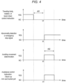
- a time period for completing the upward movement of the boom 203 depends on the vehicle size class and the weight of bucket load, so the instruction to move the boom 203 in an upward direction may be constructed so that it continues exactly during a predetermined time period (dt2 in Fig. 4 ) in proportion to the weight outputted by the loaded weight measurement device 306 and the vehicle size class held by the vehicle size class information holding section 348.
- dt2 in Fig. 4 a predetermined time period
- Step 407 is not performed. Also, if it is determined that the avoiding movement is not necessary in Steps 405-406, Step 407 is not performed.
- the machine control section 344 controls the rotary body 310, the traveling body 311 and the work machinery 309 putting priority on the avoidance control instruction over the operation control instruction.
- Step 404 may be omitted in Example 1 above. Also, Step 406 may be omitted.
Landscapes
- Engineering & Computer Science (AREA)
- Mining & Mineral Resources (AREA)
- Civil Engineering (AREA)
- General Engineering & Computer Science (AREA)
- Structural Engineering (AREA)
- Component Parts Of Construction Machinery (AREA)
- Operation Control Of Excavators (AREA)
Abstract
Description
- The present invention relates to a work machine and a work machine system.
- As back ground art, there is
JP 2019-68346 A Patent Literature 1 describes "a work vehicle comprises: an imaging device for capturing an image showing a work object; an image transmission section for transmitting the image captured by the imaging device to a control device; an operation signal receiving section for receiving an operation signal from the control device; and a movement control section for restricting the operation signal in response to transmission situation of the image". - Also, as other background art, there is
JP 2019-065661 -
- Patent Literature 1:
JP 2019-068346 A - Patent Literature 2:
JP 2019-065661 A -
Patent Literature 1 describes a mechanism for restricting the operation signal under a situation wherein abnormality arises in image transmission and the operator cannot operate the work machine appropriately. - However, even if the operation signal is restricted during operating a vehicle body and vehicle body speed is lowered, inertia of the vehicle body might cause contacting with an obstacle nearby.
- Also, in Patent Literature 2 describes a mechanism for avoiding coming into contact with a hauling vehicle without any operation of an operator by identifying a vehicle position, a direction and a soil removal position.
- However, it is desirable that coming into contact can be avoided even in cases wherein abnormality arises in a device for identifying the soil removal position, the vehicle position, the direction, etc.
- In view of the above, an object of the present invention is to reduce a risk of coming into contact with an obstacle nearby even if the vehicle body does not stop immediately due to inertia in a case wherein abnormality arises in a work machine.
- A work machine related to the present invention is characterized in that it comprises:
- a traveling body;
- a rotary body rotatably mounted onto the traveling body;
- a work machinery of an articulated type mounted to the rotary body and including a boom, an arm and a work tool; and
- a control device,
- wherein the control device comprises:
- a control instruction calculation section for calculating an operation control instruction to the traveling body, the rotary body and the work machinery in response to an operation instruction outputted from an operation input device;
- a machine control section for controlling the traveling body, the rotary body and the work tool in response to an operation control instruction of the control instruction calculation section;
- an abnormality detection section for detecting abnormality of a signal from outside of the work machine or abnormality of the work machine;
- an avoiding movement necessity determination section for distinguishing movement situation of the traveling body, the rotary body and the work machinery and determining whether an avoiding movement is necessary in a case wherein the abnormality detection section detects abnormality; and
- an avoidance control instruction section for calculating an avoidance control instruction and outputs this to the machine control section in a case wherein it is determined that the avoiding movement is necessary by the avoiding movement necessity determination section,
- wherein the machine control section controls the traveling body, the rotary body and the work machinery putting priority on the avoidance control instruction over the operation control instruction.
- The present description includes the disclosure of
Japanese Patent Application No. 2021-066428 - According to the present invention, the risk that the vehicle body comes into contact with an obstacle nearby is reduced in a case wherein abnormality arises in a work machine.
-
-
Fig. 1 is a shovel of Example 1. -
Fig. 2 is a system block diagram of Example 1. -
Fig. 3 is a flowchart of Example 1. -
Fig. 4 is avoidance control of Example 1. - An target of the present example is vehicle body control when abnormality arises in remote control of a shovel (work machine) such as shown in
Fig. 1 . The shovel comprises: arotary body 202 including acab 201; atraveling body 206; and awork machinery 309 including aboom 203, anarm 204 and abucket 205. Therotary body 202 is rotatably mounted onto thetraveling body 206. Thework machinery 309 is mounted to therotary body 202, includes theboom 203, thearm 204 and a work tool, and is constructed to be an articulated type. The work tool is thebucket 205 in this example, but this may be a hydraulics breaker / chisel, a crusher, a steel framed reinforced concrete dismantler, a reinforcing steel cutter, a fork, a fork grapple, a mounted hydraulic auger, a grass cutter, a bucket hammer, a magnet, etc. -
Fig. 2 is a system block diagram of the present example. The work machine (for example, a shovel) comprises acontrol device 307, animaging device 308, thework machinery 309, arotary body 310 and atraveling body 311. Also, the work machine comprises anattitude sensor 303, aposition sensor 305 and a loadedweight measurement device 306. - Also, the work machine system related to the present example comprises: the above work machine; an
operation input device 301 provided outside the work machine; animage display device 302; and a remote stopsignal transmission device 304. They output signals to thecontrol device 307. The remote stopsignal transmission device 304 is a device for transmitting an emergency stop signal that instructs emergency stop of the work machine and is used, for example, by a worker nearby the work machine in order to avoid an accident by the work machine. - The
operation input device 301 may be a portion of the work machine or located outside the work machine. If it is located outside the work machine, theoperation input device 301 receives an input from a remote operator. - The
operation input device 301 comprises an operationsignal generation section 332 for generating an operation signal in response to an operation of an operator and an operation signal transmission section 333 for transmitting the operation signal to the work machine. Also, the work machine comprises animaging device 308 for capturing an image around the work machine. - The
control device 307 comprises an operationsignal receiving section 342 and an imagesignal transmission section 341. The operationsignal receiving section 342 receives the operation signal transmitted by the operation signal transmission section 333 and outputs this to the controlinstruction calculation section 343. The imagesignal transmission section 341 transmits the image signal outputted by theimaging device 308 to an outside of the work machine (in this example, to the image display device 302). - The
image display device 302 comprises an imagesignal receiving section 322 for receiving the image signal transmitted by the imagesignal transmission section 341 and animage display section 331 for outputting an image to the operator. - The operator of the shovel confirms a situation around the shovel by the image captured by the
imaging device 308 and outputted by theimage display device 302. Also, the operator operates thework machinery 309, therotary body 310 and thetraveling body 311 from remote via theoperation input device 301. - The image captured by the
imaging device 308 is transmitted from the imagesignal transmission section 341 of thecontrol device 307 to the outside of the vehicle and received by the imagesignal receiving section 322 of theimage display device 302. The received image signal is outputted to the operator via theimage display section 331. - Also, the
operation input device 301 has an operation lever. If the operator operates the lever, the operationsignal generation section 332 outputs an operated angle of the lever as the operation signal. The operation signal is transmitted to the shovel via the operation signal transmission section 333 and received by the operationsignal receiving section 342 of the shovel. The operation signal is transformed into an operation control instruction such as an instructed pressure by the controlinstruction calculation section 343. - The control
instruction calculation section 343 calculates the operation control instructions to therotary body 310, the travelingbody 311 and thework machinery 309 in response to the operation instruction outputted from theoperation input device 301. - The control
instruction calculation section 343 also modifies the operation control instruction so as to stop movement toward a position of a preset specific obstacle based on a vehicle attitude sensed by theattitude sensor 303 as well as the operation signal. The position of the specific obstacle may be stored, for example, in a storage means of thecontrol device 307. The specific obstacle herein is, for example, a footing for loading soil to a dump car. If the operator operates the work machinery without noticing the footing, the controlinstruction calculation section 343 determines whether thework machinery 309, therotary body 310 or the travelingbody 311 comes into contact with the footing if it is controlled according to the operation. If it is determined that it comes into contact, the controlinstruction calculation section 343 does not perform the control according to the operation (i.e. without coming into contact with the footing), and it stops movement of thework machinery 309, therotary body 310 or the travelingbody 311. Such control can be realized as needed by those skilled in the art based on known techniques or the like. Note that avoiding the obstacle by an operation of the operator is also advantageous because the position of the dump car changes with time. - The control
instruction calculation section 343 calculates an operation control instruction in response to attitude information detected by theattitude sensor 303. For example, it determines whether a specific operation may be performed in response to the attitude of the work machine, and outputs or stops the operation control instruction in response to the result. - The
machine control section 344 controls thework machinery 309, therotary body 310 and the travelingbody 311 in response to the operation control instruction of the controlinstruction calculation section 343. - An
abnormality detection section 345 detects abnormality of a signal from outside the work machine or abnormality of the work machine. - A process of the present example is shown in the flowchart of
Fig. 3 . Hereinafter, the present example is explained according to the flowchart. The process shown in this flowchart is performed, for example, by thecontrol device 307. - In Steps 401-403 of
Fig. 3 , theabnormality detection section 345 detects the abnormality of a signal from outside or the abnormality of the work machine. - In
Step 401, it is determined whether there is abnormality in communication of the operation signal. The abnormality herein includes, communication breakdown, communication delay equal to or longer than a predetermined time, a bit error in the operation signal, abnormality of acknowledgment, etc., between the operation signal transmission section 333 and the operationsignal receiving section 342. For example, theabnormality detection section 345 detects communication delay, communication breakdown or loss of communication data arisen between the operation signal transmission section 333 and the operation signal receiving section 324 as the abnormality. If it is determined that there is abnormality, the process proceeds to Step 405. If it is determined that there is no abnormality, the process proceeds to Step 402. - In Step 402, it is determined whether there is abnormality in communication of the image signal. The abnormality herein includes, communication breakdown, communication delay equal to or longer than a predetermined time, a bit error in the image signal, abnormality of acknowledgment, etc., between the image
signal transmission section 341 and the imagesignal receiving section 322. For example, theabnormality detection section 345 detects communication delay, communication breakdown or loss of communication data arisen between the imagesignal transmission section 341 and the imagesignal receiving section 322 as the abnormality. If it is determined that there is abnormality, the process proceeds to Step 405. If it is determined that there is no abnormality, the process proceeds to Step 403. - Abnormality in communication of the operation signal or the image signal can be detected appropriately by such abnormality detection criteria.
- In
Step 403, it is determined whether there is abnormality in theattitude sensor 303. The work machine comprises theattitude sensor 303. Theattitude sensor 303 detects attitude information representing attitude of the work machine. The attitude sensor includes, for example, a potentiometer of a variable resistor type and an IMU (Inertial Measurement Unit). If it is determined that there is abnormality, the process proceeds to Step 405. If it is determined that there is no abnormality, the process proceeds to Step 404. - The control
instruction calculation section 343 calculates the operation control instruction in response to the attitude information detected by theattitude sensor 303. For example, it determines whether a specific operation may be performed in response to the attitude of the work machine, and outputs or stops the operation control instruction in response to the result. - The
abnormality detection section 345 detects signal loss or precision deterioration of theattitude sensor 303 as abnormality. Also, if the sensor output is an analog signal, the abnormality of theattitude sensor 303 may be breaking of wire or deviation from a predetermined signal level. If the sensor output is a digital signal, the abnormality of theattitude sensor 303 may be communication breakdown, deviation from predetermined communication content, receiving of a signal indicating internal abnormality, etc. Abnormality of theattitude sensor 303 can be detected appropriately by such detection criteria. - In
Step 404, the remote stopsignal receiving section 346 determines whether an emergency stop signal is received. The remote stopsignal receiving section 346 can receive the emergency stop signal. The emergency stop signal is transmitted and received, for example, as a remote signal. If it is determined that there is abnormality, the process proceeds to Step 405. If it is determined that there is no abnormality, the process is terminated. - In a case wherein the
abnormality detection section 345 detects abnormality in any of Steps 401-403 or in a case wherein the remote stopsignal receiving section 346 receives the emergency stop signal inStep 404, an avoiding movementnecessity determination section 349 distinguishes movement situation of the travelingbody 311, therotary body 310 and thework machinery 309 and determines whether avoiding movement is necessary (Steps - Appropriate determination of the avoiding movement is enabled by such specific determination criteria.
- For example, in a case wherein the
abnormality detection section 345 detects abnormality, the avoiding movementnecessity determination section 349 determines that an avoiding movement is necessary if: an instruction to move to rotate therotary body 310, an instruction to move to travel the travelingbody 311, or an instruction to move theboom 203 in a downward direction is being outputted from the controlinstruction calculation section 343; or the time period after an instruction to move to rotate therotary body 310, an instruction to move to travel the travelingbody 311, or an instruction to move theboom 203 in a downward direction is last outputted and before theabnormality detection section 345 detects the abnormality is equal to or less than a first time period. Also, an avoidance control instruction includes an instruction to move theboom 203 in an upward direction (for example, during a predetermined time period). - In
Step 405, the avoiding movementnecessity determination section 349 determines whether there is movement of therotary body 310, whether there is movement of the travelingbody 311 or whether there is movement of theboom 203 in a downward direction. If it is determined that there is any of the movements, the process proceeds to Step 406. If it is determined that there is not any of the movements, the process is terminated. - In
Step 406, it may be determined whether there is a construct and/or an obstacle above the work machine. If there is the construct and/or the obstacle, the process proceeds to Step 407. If there is no construct and/or obstacle, the process is terminated. - In Step 407 (that is, in a case wherein it is determined by the avoiding movement
necessity determination section 349 that the avoiding movement is necessary), the avoidancecontrol instruction section 350 calculates an avoidance control instruction and outputs this to themachine control section 344. - The emergency stop signal may be processed in a similar manner. For example, in
Step 404, if the remote stopsignal receiving section 346 receives the emergency stop signal, the avoiding movementnecessity determination section 349 determines that an avoiding movement is necessary if: an instruction to move to rotate therotary body 310, an instruction to move to travel the travelingbody 311, or an instruction to move theboom 203 in a downward direction is being outputted from the controlinstruction calculation section 343; or the time period after an instruction to move therotary body 310, an instruction to move the travelingbody 311, or an instruction to move theboom 203 in a downward direction is last outputted and before the remote stopsignal receiving section 346 receives the emergency stop signal is equal to or less than a first time period. Also, an avoidance control instruction includes an instruction to move theboom 203 in an upward direction (for example, during a predetermined time period). - Such determination criteria enables appropriate determination considering a free running time (for example, the time period after an instruction to move the
boom 203 is outputted and before it is determined that the avoiding movement is necessary). In particular, considering the elapsed time after it is last outputted, it can be determined appropriately whether the avoiding movement is necessary even in a modified example wherein the sensor for detecting a situation of the work machine is not provided. - A specific example will be explained using
Step 405. InStep 405, the avoiding movementnecessity determination section 349 determines whether there is movement of therotary body 310, whether there is movement of the travelingbody 311 and whether there is movement of theboom 203 in a downward direction. All of them are movement that raises risk that thework machinery 309 comes into contact with an obstacle around the vehicle body. - A specific example of determination method will be explained using
Fig. 4 . In Steps 401-404, the time instant of abnormality detection or the time instant of receiving the emergency stop signal is denoted as time instant t1. At this time, the elapsed time from the time instant at which traveling of the travelingbody 311, rotation of therotary body 310 or downward movement of theboom 203 is last instructed to the time instant t1 is denoted as dt1. - Free running time wherein the movement continues may occur after the operation control instruction is stopped. Accordingly, if dt1 is shorter than a predetermined time period (first time period), it is determined that the avoiding movement is necessary.
- Also, if inertia of the vehicle body and/or the load is large, the free running time after the operation control instruction is stopped is long. Accordingly, it may be designed so that it is determined that the avoiding movement is necessary if dt1 is shorter than a predetermined time period (second time period) corresponding to a vehicle size class of the work machine and/or a weight of the load held in the vehicle size class information holding section 348 (
Fig. 2 ). - That is, the
control device 307 may comprise the vehicle size classinformation holding section 348 that holds vehicle size class information of the work machine. And/or, the work machine may comprise the loadedweight measurement device 306 for detecting the loaded weight of the load that is loaded into the work machine. Then, in Steps 401-403, in a case wherein theabnormality detection section 345 detects abnormality, the avoiding movementnecessity determination section 349 determines that the avoiding movement is necessary if: an instruction to move therotary body 310 or an instruction to move theboom 203 in a downward direction is being outputted from the controlinstruction calculation section 343; or the time period after an instruction to move to rotate therotary body 310 or an instruction to move theboom 203 in a downward direction is last outputted and before theabnormality detection section 345 detects the abnormality is equal to or less than the second time period corresponding to the vehicle size class information and/or the loaded weight. Also, the avoidance control instruction includes an instruction to move theboom 203 in an upward direction during a predetermined time period (third time period) corresponding to the vehicle size class information and/or the loaded weight. - The avoidance control instruction outputted during the third time period may include an instruction to move the
arm 204 and thebucket 205 in a pull direction. Such a control instruction reduces a rotation radius of thework machinery 309. - The emergency stop signal may be processed in a similar manner. For example, in
Step 404, if the remote stopsignal receiving section 346 receives the emergency stop signal, the avoiding movementnecessity determination section 349 determines that an avoiding movement is necessary if: an instruction to move to rotate therotary body 310 or an instruction to move theboom 203 in a downward direction is being outputted from the controlinstruction calculation section 343; or the time period after an instruction to move therotary body 310 or an instruction to move theboom 203 in a downward direction is last outputted and before the remote stopsignal receiving section 346 receives the emergency stop signal is equal to or less than the second time period corresponding to the vehicle size class information and/or the loaded weight. Also, the avoidance control instruction includes an instruction to move theboom 203 in an upward direction during a time period (the third period) corresponding to the vehicle size class information and/or the loaded weight. - Such determination criteria enables appropriate determination considering length of the free running time.
- In
Step 406, it may be determined whether there is a construct and/or an obstacle above the work machine, in particular above thework machinery 309. The construct and/or obstacle is, for example, an electric cable, a bridge girder, ceiling in a haulage way, etc. - When the avoiding movement is performed, the
work machinery 309 may come into contact with the construct and/or obstacle above it. In order to avoid this, the work machine comprises aposition sensor 305 for detecting a position of the work machine. Theposition sensor 305 is a sensor utilizing, for example, GNSS (Global Navigation Satellite System). Note that, if the position of thework machinery 309 is to be detected, it can be calculated and determined by utilizing the GNSS provided at the work machine and based on the attitude of thework machinery 309 according to theattitude sensor 303. - For example, the avoiding movement
necessity determination section 349 determines that the avoiding movement is necessary only if there is no construct and no obstacle above the work machine. Upon determining whether there is a construct and/or an obstacle, first, the position of the work machine is obtained by theposition sensor 305. - The control device 307comprises a working area
information holding section 347 that holds corresponding relationship between positions in the working area and whether there is a construct and/or an obstacle above each position within the working area. The working areainformation holding section 347 holds whether there is a construct and/or an obstacle above each position beforehand and it can be determined whether there is the construct and/or obstacle based on the position information of theposition sensor 305. - For example, based on the position of the work machine and the corresponding relationship held within the working area
information holding section 347, the avoiding movementnecessity determination section 349 determines that the avoiding movement is not necessary regardless of the determination result of Step 405 (that is, regardless of movement situation of the travelingbody 311, therotary body 310 and the work machinery 309) if there is a construct and/or an obstacle above the position of the work machine. If not, it is determined that the avoiding movement is necessary according to the determination result ofStep 405. - Such determination suppresses the avoiding movement if there is a construct and/or an obstacle above the work machine. Accordingly, the instruction to move the
boom 203 in an upward direction is suppressed and coming into contact with the construct and/or obstacle is avoided. - In Step 407 (that is, in a case wherein it is determined that the avoiding movement is necessary by the avoiding movement necessity determination section 349), the avoidance
control instruction section 350 calculates the avoidance control instruction and outputs this to themachine control section 344. - A specific example of the avoidance control instruction will be explained below. The avoidance control instruction includes an instruction to stop the work machinery 309 (excepting the boom 203), the
rotary body 310 and the travelingbody 311. However, some work machines (for example, a shovel) have great inertia and long braking distance, so the braking might be too late and they might come into contact with an obstacle. Accordingly, in the present step, the avoidance control instruction includes an instruction to move theboom 203 to an upward direction in order to let a portion of thework machinery 309 escape upwardly wherein there is no obstacle. A time period for completing the upward movement of theboom 203 depends on the vehicle size class and the weight of bucket load, so the instruction to move theboom 203 in an upward direction may be constructed so that it continues exactly during a predetermined time period (dt2 inFig. 4 ) in proportion to the weight outputted by the loadedweight measurement device 306 and the vehicle size class held by the vehicle size classinformation holding section 348. Such control enables appropriate control considering the vehicle size class and the loaded weight. - Note that, if abnormality is not detected in Steps 401-403 and the emergency stop signal is not received in
Step 404,Step 407 is not performed. Also, if it is determined that the avoiding movement is not necessary in Steps 405-406,Step 407 is not performed. - After the process in
Fig. 3 , themachine control section 344 controls therotary body 310, the travelingbody 311 and thework machinery 309 putting priority on the avoidance control instruction over the operation control instruction. By this, the risk that the vehicle body comes into contact with an obstacle nearby in a case wherein abnormality arises in the work machine is reduced. - Step 404 may be omitted in Example 1 above. Also, Step 406 may be omitted.
-
- 101
- Operation input device
- 102
- Control device
- 103
- Work machinery
- 104
- Rotary body
- 105
- Traveling body
- 106
- Control instruction calculation section
- 107
- Machine control section
- 108
- Abnormality detection section
- 109
- Avoiding movement necessity determination section
- 110
- Avoidance control instruction section
- 202
- Rotary body
- 203
- Boom
- 204
- Arm
- 205
- Bucket (Work tool)
- 206
- Traveling body
- 230
- Boom
- 301
- Operation input device
- 302
- Image display device
- 303
- Attitude sensor
- 304
- Remote stop signal transmission device
- 305
- Position sensor
- 306
- Loaded weight measurement device
- 307
- Control device
- 308
- Imaging device
- 309
- Work machinery
- 310
- Rotary body
- 311
- Traveling body
- 322
- Image signal receiving section
- 324
- Operation signal receiving section
- 331
- Image display section
- 332
- Operation signal generation section
- 333
- Operation signal transmission section
- 341
- Image signal transmission section
- 342
- Image signal receiving section
- 343
- Control instruction calculation section
- 344
- Machine control section
- 345
- Abnormality detection section
- 346
- Remote stop signal receiving section
- 347
- Working area information holding section
- 348
- Vehicle size class information holding section
- 349
- Avoiding movement necessity determination section
- 350
- Avoidance control instruction section
- All publications, patents, and patent applications cited in the present description are incorporated in the present description by being cited as they are.
Claims (10)
- A work machine characterized in that it comprises:a traveling body;a rotary body rotatably mounted onto the traveling body;a work machinery of an articulated type mounted to the rotary body and including a boom, an arm and a work tool; anda control device,wherein the control device comprises:a control instruction calculation section for calculating an operation control instruction to the traveling body, the rotary body and the work machinery in response to an operation instruction outputted from an operation input device;a machine control section for controlling the traveling body, the rotary body and the work tool in response to an operation control instruction of the control instruction calculation section;an abnormality detection section for detecting abnormality of a signal from outside of the work machine or abnormality of the work machine;an avoiding movement necessity determination section for distinguishing movement situation of the traveling body, the rotary body and the work machinery and determining whether an avoiding movement is necessary in a case wherein the abnormality detection section detects abnormality; andan avoidance control instruction section for calculating an avoidance control instruction and outputs this to the machine control section in a case wherein it is determined that the avoiding movement is necessary by the avoiding movement necessity determination section,wherein the machine control section controls the traveling body, the rotary body and the work machinery putting priority on the avoidance control instruction over the operation control instruction.
- A work machine system comprising:the work machine according to claim 1; andthe operation input device,wherein the work machine system further comprises an image display device,wherein the image display device has:an image signal receiving section for receiving an image signal transmitted by an image signal transmission section; andan image display section for outputting an image to an operator,wherein the operation input device is located outside the work machine and receives an input of the operator,wherein the operation input device comprises:an operation signal generation section for generating an operation signal in response to an operation of the operator; andan operation signal transmission section for transmitting the operation signal to the work machine,wherein the work machine comprises an imaging device for capturing an image around the work machine,wherein the control device comprises:an operation signal receiving section for receiving the operation signal transmitted by the operation signal transmission section and outputting this to the control instruction calculation section; andthe image signal transmission section for transmitting the image signal outputted by the imaging device to an outside of the work machine,wherein the abnormality detection section detects communication delay, communication breakdown or loss of communication data arisen between the operation signal transmission section and the operation signal receiving section or between the image signal transmission section and the image signal receiving section as abnormality.
- The work machine according to claim 1, whereinthe work machine comprises an attitude sensor for detecting attitude information representing an attitude of the work machine,the control instruction calculation section of the control device calculates the operation control instruction in response to the attitude information detected by the attitude sensor, andthe abnormality detection section detects signal loss or precision deterioration of the attitude sensor as abnormality.
- A work machine system comprising the work machine according to claim 1, further comprising a remote stop signal transmission device for transmitting an emergency stop signal that instructs emergency stop of the work machine,wherein the control device comprises a remote stop signal receiving section for receiving the emergency stop signal, andwherein the avoiding movement necessity determination section distinguishes movement situation of the traveling body, the rotary body and the work machinery and determines whether avoiding movement is necessary in a case wherein the remote stop signal receiving section receives an emergency stop signal.
- The work machine according to claim 1,
wherein the avoiding movement necessity determination section determines, in a case wherein the abnormality detection section detects abnormality, that avoiding movement is necessary if:an instruction to move to rotate the rotary body, an instruction to move to travel the traveling body, or an instruction to move the boom in a downward direction is being outputted from the control instruction calculation section; ora time period after an instruction to move to rotate the rotary body, an instruction to move to travel the traveling body, or an instruction to move the boom in a downward direction is last outputted and before the abnormality detection section detects abnormality is equal to or less than a first time period,wherein the avoidance control instruction includes an instruction to move the boom in an upward direction. - The work machine system according to claim 4,
wherein the avoiding movement necessity determination section determines, in a case wherein the emergency stop signal receiving section receives the emergency stop signal, that avoiding movement is necessary if:an instruction to move to rotate the rotary body, an instruction to move to travel the traveling body, or an instruction to move the boom in a downward direction is being outputted from the control instruction calculation section; ora time period after an instruction to move to rotate the rotary body, an instruction to move to travel the traveling body, or an instruction to move the boom in a downward direction is last outputted and before the remote stop signal receiving section receives the emergency stop signal is equal to or less than a first time period,wherein the avoidance control instruction includes an instruction to move the boom in an upward direction. - The work machine according to claim 1,wherein the control device comprises a vehicle size class information holding section for holding vehicle size class information of the work machine,wherein the work machine comprises a loaded weight measurement device for detecting a loaded weight of a load that is loaded into the work machine,wherein the avoiding movement necessity determination section determines, in a case wherein the abnormality detection section detects abnormality, that avoiding movement is necessary if:- an instruction to move to rotate the rotary body or an instruction to move the boom in a downward direction is being outputted from the control instruction calculation section; or- a time period after an instruction to move to rotate the rotary body or an instruction to move the boom in a downward direction is last outputted and before the abnormality detection section detects abnormality is equal to or less than a second time period corresponding to the vehicle size class information and the loaded weight,wherein the avoidance control instruction includes an instruction to move the boom in an upward direction during a third time period corresponding to the vehicle size class information and the loaded weight.
- The work machine system according to claim 4,wherein the control device comprises a vehicle size class information holding section for holding vehicle size.class information of the work machine,wherein the work machine comprises a loaded weight measurement device for detecting a loaded weight of a load that is loaded into the work machine,wherein the avoiding movement necessity determination section determines, in a case wherein the emergency stop signal receiving section receives the emergency stop signal, that avoiding movement is necessary if:- an instruction to move to rotate the rotary body or an instruction to move the boom in a downward direction is being outputted from the control instruction calculation section; or- a time period after an instruction to move to rotate the rotary body or an instruction to move the boom in a downward direction is last outputted and before the remote stop signal receiving section receives the emergency stop signal is equal to or less than a second time period corresponding to the vehicle size class information and the loaded weight,wherein the avoidance control instruction includes an instruction to move the boom in an upward direction during a third time period corresponding to the vehicle information and the loaded weight.
- The work machine according to claim 7, wherein the avoidance control instruction outputted during the third time period includes an instruction to move an arm and a work tool in a pull direction.
- The work machine according to claim 1,wherein the work machine comprises a position sensor for detecting a position of the work machine,wherein the control device comprises a working area information holding section for holding corresponding relationship between the position and whether there is a construct or an obstacle above the position,wherein the avoiding movement necessity determination section determines that the avoiding movement is not necessary based on the position and the corresponding relationship regardless of the movement situation of the traveling body, the rotary body and the work machinery if there is a construct or an obstacle above the position.
Applications Claiming Priority (2)
| Application Number | Priority Date | Filing Date | Title |
|---|---|---|---|
| JP2021066428 | 2021-04-09 | ||
| PCT/JP2022/011785 WO2022215466A1 (en) | 2021-04-09 | 2022-03-16 | Work machine and work machine system |
Publications (3)
| Publication Number | Publication Date |
|---|---|
| EP4321692A1 true EP4321692A1 (en) | 2024-02-14 |
| EP4321692A4 EP4321692A4 (en) | 2025-03-12 |
| EP4321692B1 EP4321692B1 (en) | 2026-02-25 |
Family
ID=83546212
Family Applications (1)
| Application Number | Title | Priority Date | Filing Date |
|---|---|---|---|
| EP22784451.1A Active EP4321692B1 (en) | 2021-04-09 | 2022-03-16 | Work machine and work machine system |
Country Status (6)
| Country | Link |
|---|---|
| US (1) | US12345018B2 (en) |
| EP (1) | EP4321692B1 (en) |
| JP (1) | JP7473740B2 (en) |
| KR (1) | KR102903857B1 (en) |
| CN (1) | CN116981811B (en) |
| WO (1) | WO2022215466A1 (en) |
Families Citing this family (1)
| Publication number | Priority date | Publication date | Assignee | Title |
|---|---|---|---|---|
| CN115997061B (en) * | 2021-03-02 | 2025-10-28 | 日立建机株式会社 | Work machine |
Family Cites Families (17)
| Publication number | Priority date | Publication date | Assignee | Title |
|---|---|---|---|---|
| JP2000352078A (en) * | 1999-06-10 | 2000-12-19 | Hitachi Constr Mach Co Ltd | Construction machinery with interference prevention function |
| JP2004338817A (en) * | 2003-05-13 | 2004-12-02 | Komatsu Ltd | Work vehicle operating device |
| JP2013150233A (en) * | 2012-01-23 | 2013-08-01 | Hitachi Ltd | Remote operation system of heavy machine vehicle |
| KR102023196B1 (en) * | 2012-01-27 | 2019-09-19 | 두산인프라코어 주식회사 | Apparatus for enhancing operative safety of construction machinery |
| US20130268138A1 (en) * | 2012-04-05 | 2013-10-10 | Caterpillar Inc. | High Availability For Autonomous Machine Control System |
| US9098087B2 (en) * | 2013-02-04 | 2015-08-04 | Caterpillar Inc. | System and method for adjusting the operation of a machine |
| US9560692B2 (en) * | 2014-01-13 | 2017-01-31 | Caterpillar Inc. | Controlling a machine in remote or autonomous mode |
| JP6361592B2 (en) * | 2015-06-26 | 2018-07-25 | 株式会社デンソー | Vehicle control device |
| JP6794667B2 (en) | 2016-06-07 | 2020-12-02 | 株式会社Ihi | Construction machinery control system and control program |
| JP6933545B2 (en) | 2017-10-04 | 2021-09-08 | 株式会社小松製作所 | Work vehicle, control device, and work vehicle control method |
| JP7015133B2 (en) | 2017-10-04 | 2022-02-02 | 株式会社小松製作所 | Work system, work machine and control method |
| JP7216472B2 (en) | 2017-10-04 | 2023-02-01 | 株式会社小松製作所 | Working system and control method |
| JP7119457B2 (en) * | 2018-03-19 | 2022-08-17 | コベルコ建機株式会社 | construction machinery |
| JP2020193503A (en) * | 2019-05-29 | 2020-12-03 | ナブテスコ株式会社 | Operation support system of work machine, operation support method of work machine, maintenance support method of operation support system, and construction machine |
| JP7165636B2 (en) | 2019-08-30 | 2022-11-04 | 日立建機株式会社 | working machine |
| TWI729929B (en) | 2019-10-18 | 2021-06-01 | 穎華科技股份有限公司 | Light-guide sunroof assembly |
| WO2022202918A1 (en) * | 2021-03-26 | 2022-09-29 | 住友重機械工業株式会社 | Excavator and system for assisting excavator construction |
-
2022
- 2022-03-16 US US18/279,413 patent/US12345018B2/en active Active
- 2022-03-16 EP EP22784451.1A patent/EP4321692B1/en active Active
- 2022-03-16 WO PCT/JP2022/011785 patent/WO2022215466A1/en not_active Ceased
- 2022-03-16 CN CN202280017238.8A patent/CN116981811B/en active Active
- 2022-03-16 JP JP2023512892A patent/JP7473740B2/en active Active
- 2022-03-16 KR KR1020237029041A patent/KR102903857B1/en active Active
Also Published As
| Publication number | Publication date |
|---|---|
| WO2022215466A1 (en) | 2022-10-13 |
| EP4321692A4 (en) | 2025-03-12 |
| CN116981811A (en) | 2023-10-31 |
| US12345018B2 (en) | 2025-07-01 |
| KR20230134588A (en) | 2023-09-21 |
| JPWO2022215466A1 (en) | 2022-10-13 |
| EP4321692B1 (en) | 2026-02-25 |
| JP7473740B2 (en) | 2024-04-23 |
| US20240191472A1 (en) | 2024-06-13 |
| CN116981811B (en) | 2026-01-23 |
| KR102903857B1 (en) | 2025-12-24 |
Similar Documents
| Publication | Publication Date | Title |
|---|---|---|
| AU2021200371B2 (en) | Work system, work machine, and control method | |
| JP7717782B2 (en) | Work systems and methods | |
| US11359349B2 (en) | Work vehicle, work management system, and work vehicle control method | |
| US11427984B2 (en) | Work machine | |
| US8833861B2 (en) | Loading analysis system and method | |
| AU2018405686B2 (en) | Loading machine control device and control method | |
| CN111771031A (en) | System and method for controlling a work machine | |
| CN113474517A (en) | Working machine | |
| EP4321692B1 (en) | Work machine and work machine system | |
| US12264452B2 (en) | Work machine | |
| EP4446500A1 (en) | Work machine | |
| EP4328389A1 (en) | Monitoring system | |
| US12497757B2 (en) | Control system for work machine | |
| JPWO2022215466A5 (en) | ||
| US20230392346A1 (en) | System for mitigation of unintentional working machine movement | |
| WO2026004257A1 (en) | Automatic rotation control system, work machine, and automatic rotation control method for work machine | |
| JP2026046360A (en) | Automatic rotation control system for a work machine, work machine, and method for automatic rotation control of a work machine | |
| JPH1018353A (en) | Remotely controlled work machine | |
| WO2026055407A1 (en) | Work vehicle control system and method for avoiding collisions with overhead objects |
Legal Events
| Date | Code | Title | Description |
|---|---|---|---|
| STAA | Information on the status of an ep patent application or granted ep patent |
Free format text: STATUS: THE INTERNATIONAL PUBLICATION HAS BEEN MADE |
|
| PUAI | Public reference made under article 153(3) epc to a published international application that has entered the european phase |
Free format text: ORIGINAL CODE: 0009012 |
|
| STAA | Information on the status of an ep patent application or granted ep patent |
Free format text: STATUS: REQUEST FOR EXAMINATION WAS MADE |
|
| 17P | Request for examination filed |
Effective date: 20231109 |
|
| AK | Designated contracting states |
Kind code of ref document: A1 Designated state(s): AL AT BE BG CH CY CZ DE DK EE ES FI FR GB GR HR HU IE IS IT LI LT LU LV MC MK MT NL NO PL PT RO RS SE SI SK SM TR |
|
| DAV | Request for validation of the european patent (deleted) | ||
| DAX | Request for extension of the european patent (deleted) | ||
| A4 | Supplementary search report drawn up and despatched |
Effective date: 20250206 |
|
| RIC1 | Information provided on ipc code assigned before grant |
Ipc: E02F 3/43 20060101ALI20250131BHEP Ipc: E02F 9/26 20060101ALI20250131BHEP Ipc: E02F 9/24 20060101ALI20250131BHEP Ipc: E02F 9/20 20060101AFI20250131BHEP |
|
| GRAJ | Information related to disapproval of communication of intention to grant by the applicant or resumption of examination proceedings by the epo deleted |
Free format text: ORIGINAL CODE: EPIDOSDIGR1 |
|
| GRAP | Despatch of communication of intention to grant a patent |
Free format text: ORIGINAL CODE: EPIDOSNIGR1 |
|
| GRAP | Despatch of communication of intention to grant a patent |
Free format text: ORIGINAL CODE: EPIDOSNIGR1 |
|
| STAA | Information on the status of an ep patent application or granted ep patent |
Free format text: STATUS: GRANT OF PATENT IS INTENDED |
|
| INTG | Intention to grant announced |
Effective date: 20251212 |
|
| GRAS | Grant fee paid |
Free format text: ORIGINAL CODE: EPIDOSNIGR3 |
|
| GRAA | (expected) grant |
Free format text: ORIGINAL CODE: 0009210 |
|
| STAA | Information on the status of an ep patent application or granted ep patent |
Free format text: STATUS: THE PATENT HAS BEEN GRANTED |
|
| AK | Designated contracting states |
Kind code of ref document: B1 Designated state(s): AL AT BE BG CH CY CZ DE DK EE ES FI FR GB GR HR HU IE IS IT LI LT LU LV MC MK MT NL NO PL PT RO RS SE SI SK SM TR |
|
| REG | Reference to a national code |
Ref country code: CH Ref legal event code: F10 Free format text: ST27 STATUS EVENT CODE: U-0-0-F10-F00 (AS PROVIDED BY THE NATIONAL OFFICE) Effective date: 20260225 Ref country code: GB Ref legal event code: FG4D |
|
| REG | Reference to a national code |
Ref country code: DE Ref legal event code: R096 Ref document number: 602022031198 Country of ref document: DE |
|
| REG | Reference to a national code |
Ref country code: IE Ref legal event code: FG4D |
|
| PGFP | Annual fee paid to national office [announced via postgrant information from national office to epo] |
Ref country code: GB Payment date: 20260324 Year of fee payment: 5 |
|
| PGFP | Annual fee paid to national office [announced via postgrant information from national office to epo] |
Ref country code: DE Payment date: 20260331 Year of fee payment: 5 |
|
| PGFP | Annual fee paid to national office [announced via postgrant information from national office to epo] |
Ref country code: AT Payment date: 20260301 Year of fee payment: 5 |
|
| REG | Reference to a national code |
Ref country code: NL Ref legal event code: MP Effective date: 20260225 |
|
| PG25 | Lapsed in a contracting state [announced via postgrant information from national office to epo] |
Ref country code: RS Free format text: LAPSE BECAUSE OF FAILURE TO SUBMIT A TRANSLATION OF THE DESCRIPTION OR TO PAY THE FEE WITHIN THE PRESCRIBED TIME-LIMIT Effective date: 20260525 |
|
| PG25 | Lapsed in a contracting state [announced via postgrant information from national office to epo] |
Ref country code: ES Free format text: LAPSE BECAUSE OF FAILURE TO SUBMIT A TRANSLATION OF THE DESCRIPTION OR TO PAY THE FEE WITHIN THE PRESCRIBED TIME-LIMIT Effective date: 20260225 |
|
| PG25 | Lapsed in a contracting state [announced via postgrant information from national office to epo] |
Ref country code: PL Free format text: LAPSE BECAUSE OF FAILURE TO SUBMIT A TRANSLATION OF THE DESCRIPTION OR TO PAY THE FEE WITHIN THE PRESCRIBED TIME-LIMIT Effective date: 20260225 |
|
| PG25 | Lapsed in a contracting state [announced via postgrant information from national office to epo] |
Ref country code: GR Free format text: LAPSE BECAUSE OF FAILURE TO SUBMIT A TRANSLATION OF THE DESCRIPTION OR TO PAY THE FEE WITHIN THE PRESCRIBED TIME-LIMIT Effective date: 20260526 |
|
| REG | Reference to a national code |
Ref country code: LT Ref legal event code: MG9D |
|
| PG25 | Lapsed in a contracting state [announced via postgrant information from national office to epo] |
Ref country code: LT Free format text: LAPSE BECAUSE OF FAILURE TO SUBMIT A TRANSLATION OF THE DESCRIPTION OR TO PAY THE FEE WITHIN THE PRESCRIBED TIME-LIMIT Effective date: 20260225 |
|
| PG25 | Lapsed in a contracting state [announced via postgrant information from national office to epo] |
Ref country code: NO Free format text: LAPSE BECAUSE OF FAILURE TO SUBMIT A TRANSLATION OF THE DESCRIPTION OR TO PAY THE FEE WITHIN THE PRESCRIBED TIME-LIMIT Effective date: 20260525 |
|
| PG25 | Lapsed in a contracting state [announced via postgrant information from national office to epo] |
Ref country code: AT Free format text: LAPSE BECAUSE OF FAILURE TO SUBMIT A TRANSLATION OF THE DESCRIPTION OR TO PAY THE FEE WITHIN THE PRESCRIBED TIME-LIMIT Effective date: 20260225 Ref country code: FI Free format text: LAPSE BECAUSE OF FAILURE TO SUBMIT A TRANSLATION OF THE DESCRIPTION OR TO PAY THE FEE WITHIN THE PRESCRIBED TIME-LIMIT Effective date: 20260225 Ref country code: SE Free format text: LAPSE BECAUSE OF FAILURE TO SUBMIT A TRANSLATION OF THE DESCRIPTION OR TO PAY THE FEE WITHIN THE PRESCRIBED TIME-LIMIT Effective date: 20260225 |
|
| REG | Reference to a national code |
Ref country code: AT Ref legal event code: MK05 Ref document number: 1890943 Country of ref document: AT Kind code of ref document: T Effective date: 20260225 |
|
| PG25 | Lapsed in a contracting state [announced via postgrant information from national office to epo] |
Ref country code: HR Free format text: LAPSE BECAUSE OF FAILURE TO SUBMIT A TRANSLATION OF THE DESCRIPTION OR TO PAY THE FEE WITHIN THE PRESCRIBED TIME-LIMIT Effective date: 20260225 |
|
| PG25 | Lapsed in a contracting state [announced via postgrant information from national office to epo] |
Ref country code: PT Free format text: LAPSE BECAUSE OF FAILURE TO SUBMIT A TRANSLATION OF THE DESCRIPTION OR TO PAY THE FEE WITHIN THE PRESCRIBED TIME-LIMIT Effective date: 20260625 Ref country code: IS Free format text: LAPSE BECAUSE OF FAILURE TO SUBMIT A TRANSLATION OF THE DESCRIPTION OR TO PAY THE FEE WITHIN THE PRESCRIBED TIME-LIMIT Effective date: 20260625 |
|
| PG25 | Lapsed in a contracting state [announced via postgrant information from national office to epo] |
Ref country code: NL Free format text: LAPSE BECAUSE OF FAILURE TO SUBMIT A TRANSLATION OF THE DESCRIPTION OR TO PAY THE FEE WITHIN THE PRESCRIBED TIME-LIMIT Effective date: 20260225 |
|
| PG25 | Lapsed in a contracting state [announced via postgrant information from national office to epo] |
Ref country code: LV Free format text: LAPSE BECAUSE OF FAILURE TO SUBMIT A TRANSLATION OF THE DESCRIPTION OR TO PAY THE FEE WITHIN THE PRESCRIBED TIME-LIMIT Effective date: 20260225 |
|
| PG25 | Lapsed in a contracting state [announced via postgrant information from national office to epo] |
Ref country code: BG Free format text: LAPSE BECAUSE OF FAILURE TO SUBMIT A TRANSLATION OF THE DESCRIPTION OR TO PAY THE FEE WITHIN THE PRESCRIBED TIME-LIMIT Effective date: 20260225 |