EP4321687B1 - Rotating construction platform based on monopile - Google Patents
Rotating construction platform based on monopile Download PDFInfo
- Publication number
- EP4321687B1 EP4321687B1 EP21938812.1A EP21938812A EP4321687B1 EP 4321687 B1 EP4321687 B1 EP 4321687B1 EP 21938812 A EP21938812 A EP 21938812A EP 4321687 B1 EP4321687 B1 EP 4321687B1
- Authority
- EP
- European Patent Office
- Prior art keywords
- platform
- monopile
- working platform
- construction
- underframe
- Prior art date
- Legal status (The legal status is an assumption and is not a legal conclusion. Google has not performed a legal analysis and makes no representation as to the accuracy of the status listed.)
- Active
Links
Images



Classifications
-
- E—FIXED CONSTRUCTIONS
- E02—HYDRAULIC ENGINEERING; FOUNDATIONS; SOIL SHIFTING
- E02B—HYDRAULIC ENGINEERING
- E02B17/00—Artificial islands mounted on piles or like supports, e.g. platforms on raisable legs or offshore constructions; Construction methods therefor
-
- E—FIXED CONSTRUCTIONS
- E02—HYDRAULIC ENGINEERING; FOUNDATIONS; SOIL SHIFTING
- E02B—HYDRAULIC ENGINEERING
- E02B17/00—Artificial islands mounted on piles or like supports, e.g. platforms on raisable legs or offshore constructions; Construction methods therefor
- E02B17/0034—Maintenance, repair or inspection of offshore constructions
-
- E—FIXED CONSTRUCTIONS
- E02—HYDRAULIC ENGINEERING; FOUNDATIONS; SOIL SHIFTING
- E02B—HYDRAULIC ENGINEERING
- E02B17/00—Artificial islands mounted on piles or like supports, e.g. platforms on raisable legs or offshore constructions; Construction methods therefor
- E02B2017/0056—Platforms with supporting legs
- E02B2017/0065—Monopile structures
Definitions
- the present disclosure relates to a construction platform surrounded by water, in particular, to a rotating construction platform based on a monopile.
- Document CN104594317 forms background art which can be regarded as useful to understand the invention. It discloses a single-pile foundation with a platform fixed on top.
- the present disclosure aims to provide a rotating construction platform based on a monopile.
- a new design pattern is proposed to directly set the construction platform on the monopile, which saves construction time and costs, improves the continuity of construction operations, and ensures construction quality.
- the present disclosure provides a rotating construction platform based on a monopile, including a rotary connecting mechanism arranged on a top of the monopile and a working platform arranged on the rotary connecting mechanism.
- the rotary connecting mechanism includes an upper connecting tube, a lower connecting tube, and a rotary support structure located between the upper connecting tube and the lower connecting tube.
- the working platform is fixedly connected to the upper connecting tube, and the lower connecting tube is detachably fixed to the top of the monopile. At least one side of the working platform sticks out of a side of the monopile.
- the rotary connecting mechanism further includes a plurality of corbels fixedly connected to the upper connecting tube, and the working platform is fixedly connected to the plurality of corbels.
- a plurality of horizontal braces is fixedly arranged between the plurality of corbels and the upper connecting tube.
- a load-bearing system of the working platform includes a platform underframe.
- the platform underframe is fixedly connected with a plurality of short columns, each of the plurality of short columns is fixedly connected to one of the plurality of corbels of the rotary connecting mechanism.
- the platform underframe is rectangular and sticks out of one side or two sides of the monopile along a length direction.
- the platform underframe includes a plurality of main beams arranged along the length direction, a plurality of secondary beams arranged along a width direction, and each steel plate or grating installed on the main beam and the secondary beam.
- the plurality of short columns is fixedly connected with the plurality of main beams.
- the load-bearing system of the working platform further includes a vertical reinforcement structure fixedly connected with the platform underframe.
- the load-bearing system of the working platform including the platform underframe and the vertical reinforcement structure is a frame structure, a truss structure, a self-stressed arch system, or a cable-stayed structure.
- the rotary connecting mechanism further includes a rotary control system for controlling the rotation of the rotary support structure.
- a berthing and boarding structure is provided at a side of the working platform.
- the working platform includes a plurality of guardrails and a plurality of wheel guard sills installed on the platform underframe.
- the rotating construction platform involved in the present disclosure has the following beneficial effects:
- the rotating construction platform involved in the present disclosure adopts a new design pattern, which sets the rotating construction platform on the monopile 1. That is, the monopile 1 is used as the structural support, and there is no need to use additional piles.
- the rotary connecting mechanism 2 By setting the rotary connecting mechanism 2 with a rotation function, the upper connecting tube 22 rotates relative to the lower connecting tube 21 through the rotary support structure 23, thereby driving the working platform 3 to rotate.
- the working platform 3 can rotate according to actual construction needs. Therefore, the working platform 3 only needs to stick a long distance in one direction (referred to as the length direction) from the monopile 1, while the size of the width is small.
- the working platform 3 can be moved to the position where construction is needed by rotating, which is flexible and can effectively reduce the overall size of the working platform 3 under the condition of achieving the same construction range, thus bringing convenience to construction.
- the rotating construction platform of the present disclosure is stable and reliable and can replace the original method of using offshore construction vessels or temporary construction platforms, reduce adverse effects such as tide level, waves and water current in marine environments, improve the continuity of construction operations, save construction time and costs, avoid vessel machinery from hitting the monopile 1 due to waves when the construction space is small, improve construction positioning accuracy, and ensure construction quality.
- the rotary connecting mechanism 2 further includes multiple corbels 24 fixedly connected to the upper connecting tube 22, where the working platform 3 is fixedly connected to the corbels 24.
- Multiple corbels 24 are provided and reasonably distributed inside and outside the upper connecting tube 22.
- Multiple horizontal braces 25 are also fixedly connected between the corbels 24 and the upper connecting tube 22 to further stabilize and support.
- the corbels 24 facilitate the installation between the rotary connecting mechanism 2 and the working platform 3 and increase the support to the working platform 3.
- a flange is provided on the corbels 24, and the working platform 3 is connected to the flanges on the corbels 24 by bolts.
- the rotary support structure 23 generally includes two steel seat rings that can rotate relative to each other.
- the rotary support structure 23 can simultaneously withstand axial force, radial force, and overturning moment.
- the form of the rotary support structure 23 can be single-row four-point contact ball type, single-row cross roller type, double-row or double-column ball type, three-row roller type, ball-column combination type, etc.
- the rotary connecting mechanism 2 further includes a rotary control system that controls the rotation of the rotary support structure 23.
- the working platform 3 can be efficiently and accurately rotated and positioned to different construction angles and temporarily fixed through the rotary control system.
- the load-bearing system of the working platform 3 includes a platform underframe 31.
- the platform underframe 31 is the main structure for carrying equipment 5 and personnel activities.
- the platform underframe 31 is fixed with multiple short columns 32.
- the short columns 32 can extend downward to the bottom of the platform underframe 31.
- the lower end of each of the short columns 32 is fixedly connected to the flange of one of the corbels 24 in the rotary connecting mechanism 2 through a bolt.
- the platform underframe 31 is rectangular. In the length direction, both sides of the platform underframe 31 stick out a long distance of the monopile 1.
- the width of the platform underframe 31 does not need to be too large, just meet the needs of equipment and technology. Therefore, the area of the platform underframe 31 does not need to be too large.
- the platform underframe 31 can cover a large construction area. Therefore, the platform underframe 31 can adopt a simplified structure as much as possible.
- the platform underframe 31 includes multiple main beams 312 arranged along the length direction, multiple secondary beams 313 arranged along the width direction, and a steel plate or grating 314 installed on the main beams 312 and the secondary beams 313.
- the short columns 32 are fixedly connected to the main beams 312.
- the boundary beams 311 of the platform underframe 31 ensure that the overall torsional strength of the platform underframe 31.
- a hole 315 is locally provided on the platform underframe 31 for convenience in construction.
- the working platform 3 includes one or more guardrails 33 and one or more wheel guard sills 34 set at the edge of the platform underframe 31 for safety protection.
- a berthing and boarding structure 6 is also provided at the side of the working platform 3 to facilitate personnel boarding and disembarking.
- life-saving and escape facilities are also provided on the working platform 3, and necessary sunshade, rainproof and windproof facilities are provided.
- the working platform 3 is also equipped with basic lightning protection facilities.
- a plurality of track beams 8, a plurality of guide rails 7, a plurality of equipment holders, embedded bolts, etc. are provided on the working platform 3 for installation and movement of a material bin 4 such as an oil tank, a water tank, and a cement silo, as well as for installation and movement of equipment 5 such as a diesel generator, an air compressor, a mud pump, a high-pressure grouting machine, a cement mixing pile driver, a small crane, and a small drilling machine.
- Lifting points are also set on the working platform 3 for platform lifting and installation.
- the material bin 4 and equipment 5 can be lifted by a crane ship to the working platform 3 or temporarily fixed on the working platform 3 in advance and then hoisted together with the platform as a whole.
- the lower connecting tube 21 of the rotary connecting mechanism 2 is fixedly connected to the monopile by bolts, such that the rotating construction platform can be flexibly removed from the monopile 1 and can be reused without affecting the subsequent use of the monopile 1.
- the load-bearing system of the working platform 3 further includes a vertical reinforcement structure 35.
- the vertical reinforcement structure 35 includes columns 351 and beams 353. Specifically, the number of columns 351 is determined according to actual needs.
- the lower ends of the columns 351 are fixed on the platform underframe 31, and beams 353 are horizontally fixed on the columns 351.
- the columns 351 and the beams 353 together with the platform underframe 31 form a frame structure to ensure the strength and rigidity of the entire working platform 3, improve the bearing capacity, and reduce the deformation of the working platform 3 due to loads.
- the vertical reinforcement structure 35 of the working platform 3 includes columns 351, bracing system 352 and beams 353. Adjacent two columns 351 (also known as each span) are fixedly connected by bracing system 352 to improve the stress state of joints of beams and columns. Columns 351, bracing system 352 and beams 353 together with the platform underframe 31 form a braced frame structure to further increase the overall strength and rigidity of the working platform 3.
- the vertical reinforcement structure 35 of the load-bearing system of the working platform 3 includes tie rods 354 and an arch 355. Specifically, two ends of the arch 355 are fixedly connected to the platform underframe 31, and the tie rods 354 are fixedly connected between the arch 355 and the platform underframe 31.
- the tie rods 354 are arranged along the length direction of platform underframe 31.
- the tie rods 354 and the arch 355 together with the platform underframe 31 form a self-stressed arch system to ensure the strength and rigidity of the entire working platform 3.
- the vertical reinforcement structure 35 of the load-bearing system of the working platform 3 includes a cable tower 356 and cables 357.
- the cable tower 356 is fixed on the platform underframe 31 and located near the middle of platform underframe 31. Cables 357 are multiple and their upper ends are fixedly connected to the top of the cable tower 356 while their lower ends are fixedly connected to different positions of the platform underframe 31.
- the cable tower 356 and the cables 357 together with the platform underframe 31 form a cable-stayed structure to ensure the strength and rigidity of the entire working platform 3.
- the vertical reinforcement structure 35 of the load-bearing system of the working platform 3 includes web members 359 and upper chord members 358.
- multiple web members 359 are set according to actual needs, including vertical setting and inclined setting.
- the lower ends of the web members 359 are fixed on the platform underframe 31 while the upper chord members 358 are horizontally fixed on the web members 359.
- the web members 359 and the upper chord members 358 together with the platform underframe 31 form a truss structure to ensure the strength and rigidity of the entire working platform 3.
- the bearing capacity of the working platform 3 can be improved and its deformation due to loads can be reduced.
- This embodiment is basically similar to Embodiment 1, but different in that the platform underframe 31 of the working platform 3 sticks out of one side along the length direction of the monopile 1 for a long distance, and only slightly sticks out of the other side of the monopile 1, that is, the working platform 3 sticks out of one side only.
- This embodiment can be used in cases where the platform area does not need to be very large, reducing the structure of the working platform 3 and reducing the weight of the platform itself. However, higher technical requirements for the layout of the equipment 5 and the material bin 4 for construction are needed.
- the rotating construction platform of the present disclosure uses the top of the monopile 1 as a supporting foundation. With the increase of the diameter of the offshore monopile, the area of the pile top increases, which has sufficient rigidity and enhances the bearing capacity of the monopile. It can support a rotating platform stably and reliably. Through this rotating construction platform, construction around the monopile 1 can be effectively completed, such as pile foundation reinforcement (such as replacement method, high-pressure rotary spraying method, cement mixing method).
- pile foundation reinforcement such as replacement method, high-pressure rotary spraying method, cement mixing method.
- the rotating construction platform reduces the size of the platform under the premise of achieving the same construction scope, which brings convenience to construction and has practical engineering significance.
- the rotating construction platform of the present disclosure can also be used for construction of anti-scouring facilities around the pile (sand quilt placement, stone throwing around the pile, artificial block throwing around the pile, solidified soil anti-scouring layer), installation of auxiliary facilities, anti-corrosion coating repair and other constructions. It can also be used as a temporary surveying, observation, and testing platform. In addition to being applied to offshore monopiles, based on the same or similar principles, it can also be applied to monopiles in water bodies such as lakes and rivers.
- the present disclosure effectively overcomes various disadvantages of the traditional technology and has high industrial application values.
Landscapes
- Engineering & Computer Science (AREA)
- General Engineering & Computer Science (AREA)
- Mechanical Engineering (AREA)
- Civil Engineering (AREA)
- Structural Engineering (AREA)
- Foundations (AREA)
- Placing Or Removing Of Piles Or Sheet Piles, Or Accessories Thereof (AREA)
Description
- The present disclosure relates to a construction platform surrounded by water, in particular, to a rotating construction platform based on a monopile. Document
CN104594317 forms background art which can be regarded as useful to understand the invention. It discloses a single-pile foundation with a platform fixed on top. - During the construction, equipment installation and maintenance of offshore structures, it is often necessary to carry out construction around a monopile. At present, there are usually two ways of offshore construction:
- using conventional temporary multi-pile platforms and using offshore
- construction vessels. If conventional temporary multi-pile platforms are used, there are usually two ways: one is to build a small temporary platform beside of the monopile, where the temporary platform is supported by multiple steel pipe piles with small diameters, this method requires continuous piling and disassembly of the platform to adjust the position of the temporary platform around the monopile to meet the construction needs; the other is to reserve a hole in the middle of a very large temporary platform and surround the entire monopile in the hole, in this method, the temporary platform is too large, and this method is technically and economically unreasonable. If offshore construction vessels are used, special offshore construction vessels (such as DCM mixing ships) can be used, or construction equipment can be installed on ships, that is, land-based construction machinery are installed and arranged on a barge or a self-elevating platform vessel. Special offshore construction vessels have high construction efficiency, but their size is generally large, their construction period is tight, and their equipment is expensive; in addition, upgrading a vessel generally requires that the relevant equipment be properly configured and fixed. Except for self-elevating platform vessels, other vessels need to be moved constantly by adjusting the length of anchor chain during offshore construction. During offshore construction, environmental factors such as current load, wave load, and sea wind need to be overcome, and it is not easy to control the quality of construction. For self-elevating platform vessels, it is needed to plug and unplug leg piles and adjust their positions, thus the work efficiency is low and the technical economy is unreasonable. Therefore, a new type of construction platform is needed to reduce construction difficulty, save construction time and costs.
- Given the shortcomings of the prior art described above, the present disclosure aims to provide a rotating construction platform based on a monopile. A new design pattern is proposed to directly set the construction platform on the monopile, which saves construction time and costs, improves the continuity of construction operations, and ensures construction quality.
- To realize the above purpose, the present disclosure provides a rotating construction platform based on a monopile, including a rotary connecting mechanism arranged on a top of the monopile and a working platform arranged on the rotary connecting mechanism. The rotary connecting mechanism includes an upper connecting tube, a lower connecting tube, and a rotary support structure located between the upper connecting tube and the lower connecting tube. The working platform is fixedly connected to the upper connecting tube, and the lower connecting tube is detachably fixed to the top of the monopile. At least one side of the working platform sticks out of a side of the monopile.
- Further, the rotary connecting mechanism further includes a plurality of corbels fixedly connected to the upper connecting tube, and the working platform is fixedly connected to the plurality of corbels.
- Further, a plurality of horizontal braces is fixedly arranged between the plurality of corbels and the upper connecting tube.
- Further, a load-bearing system of the working platform includes a platform underframe. The platform underframe is fixedly connected with a plurality of short columns, each of the plurality of short columns is fixedly connected to one of the plurality of corbels of the rotary connecting mechanism.
- Further, the platform underframe is rectangular and sticks out of one side or two sides of the monopile along a length direction. The platform underframe includes a plurality of main beams arranged along the length direction, a plurality of secondary beams arranged along a width direction, and each steel plate or grating installed on the main beam and the secondary beam. The plurality of short columns is fixedly connected with the plurality of main beams.
- Further, the load-bearing system of the working platform further includes a vertical reinforcement structure fixedly connected with the platform underframe.
- Further, the load-bearing system of the working platform including the platform underframe and the vertical reinforcement structure is a frame structure, a truss structure, a self-stressed arch system, or a cable-stayed structure.
- Further, the rotary connecting mechanism further includes a rotary control system for controlling the rotation of the rotary support structure.
- Further, a berthing and boarding structure is provided at a side of the working platform.
- Further, the working platform includes a plurality of guardrails and a plurality of wheel guard sills installed on the platform underframe.
- As described above, the rotating construction platform involved in the present disclosure has the following beneficial effects:
- By setting up a rotary connecting mechanism on the top of a monopile and a working platform on the rotary connecting mechanism, a new design pattern is provided to set up the rotating construction platform on the monopile, that is, to use the monopile as a structural support without additional piles. By setting up the rotary connecting mechanism with a rotation function to drive the working platform to rotate, the overall size of the working platform can be effectively reduced under the premise of achieving the same construction scope, which brings convenience to construction. The rotating construction platform of the present disclosure is stable and reliable. It can replace the original method that requires offshore construction vessels or conventional temporary platforms, reduce adverse effects such as tide level, waves and water current in marine environments, improve the continuity of construction operations, save construction time and costs, avoid vessel machinery from hitting the monopile due to waves when the construction space is small, improve construction positioning accuracy, and ensure construction quality.
-
-
Figure 1 is a schematic diagram of a rotating construction platform according toEmbodiment 1 of the present disclosure. -
Figure 2 is a top view ofFigure 1 . -
Figure 3 is a top view of a rotary connecting mechanism according toEmbodiment 1 of the present disclosure. -
Figure 4 is a schematic diagram of a platform underframe of a working platform according toEmbodiment 1 of the present disclosure. -
Figure 5 is a front view of a working platform according toEmbodiment 1 of the present disclosure. -
Figure 6 is a schematic diagram of a working platform of a rotating construction platform according toEmbodiment 2 of the present disclosure. -
Figure 7 is a schematic diagram of a working platform of a rotating construction platform according toEmbodiment 3 of the present disclosure. -
Figure 8 is a schematic diagram of a working platform of a rotating construction platform according toEmbodiment 4 of the present disclosure. -
Figure 9 is a schematic diagram of a working platform of a rotating construction platform according toEmbodiment 5 of the present disclosure. -
Figure 10 is a schematic diagram of a working platform of a rotating construction platform according toEmbodiment 6 of the present disclosure. -
- 1
- Monopile
- 2
- Rotary connecting mechanism
- 21
- Lower connecting tube
- 22
- Upper connecting tube
- 23
- Rotary support structure
- 24
- Corbel
- 25
- Horizontal brace
- 3
- Working platform
- 31
- Platform underframe
- 311
- Boundary beam
- 312
- Main beam
- 313
- Secondary beam
- 314
- Steel plate and grating
- 315
- Hole
- 32
- Short column
- 33
- Guardrail
- 34
- Wheel guard sill
- 35
- Vertical reinforcement structure
- 351
- Column
- 352
- Bracing system
- 353
- Beam
- 354
- Tie rod
- 355
- Arch
- 356
- Cable tower
- 357
- Cable
- 358
- Upper chord member
- 359
- Web member
- 4
- Material bin
- 5
- Equipment
- 6
- Berthing and boarding structure
- 7
- Guide rail
- 8
- Track beam
- The embodiments of the present disclosure will be described below through specific embodiments. Those skilled in the art can easily understand other advantages and effects of the present disclosure according to the contents disclosed by the specification.
- It should be understood that the structures, proportions, sizes, and the like, which are illustrated in the drawings of the present specification, are used to clarify the contents disclosed in the specification for understanding and reading by those skilled, and are not intended to limit the implementation of the present disclosure, thus are not technically meaningful. Any modification of the structure, change of the scale, or adjustment of the size should still fall within the scope of the technical contents disclosed by the present disclosure without affecting the effects and achievable objectives of the present disclosure. In the meantime, the terms "upper", "lower", "left", "right", "intermediate" as used in this specification are also for the convenience of description, and are not intended to limit the scope of the present disclosure, and the change or adjustment of the relative relationship is considered to be within the scope of the present disclosure without substantial changes in technology.
- Please refer to
figures 1 to 10 . The present disclosure provides a rotating construction platform based on amonopile 1, which includes arotary connecting mechanism 2 set on the top of themonopile 1 and a workingplatform 3 set on therotary connecting mechanism 2. Therotary connecting mechanism 2 includes an upper connectingtube 22, a lower connectingtube 21, and arotary support structure 23 located between the upper connectingtube 22 and the lower connectingtube 21. The workingplatform 3 is fixedly connected to the upper connectingtube 22, and the lower connectingtube 21 is detachably fixed to the top of themonopile 1. At least one side of the workingplatform 3 sticks out of the side of themonopile 1. - As the diameter of the
offshore monopile 1 increases, the area of the pile top increases, and the bearing capacity of themonopile 1 is enhanced with sufficient rigidity. Some construction machinery (such as high-pressure rotary jet drilling machines and cement grouting machines) have small size, low self-weight, and construction load. Therefore, it is feasible to arrange a rotating construction platform on the pile top of amonopile 1. - The rotating construction platform involved in the present disclosure adopts a new design pattern, which sets the rotating construction platform on the
monopile 1. That is, themonopile 1 is used as the structural support, and there is no need to use additional piles. By setting therotary connecting mechanism 2 with a rotation function, the upper connectingtube 22 rotates relative to the lower connectingtube 21 through therotary support structure 23, thereby driving the workingplatform 3 to rotate. The workingplatform 3 can rotate according to actual construction needs. Therefore, the workingplatform 3 only needs to stick a long distance in one direction (referred to as the length direction) from themonopile 1, while the size of the width is small. The workingplatform 3 can be moved to the position where construction is needed by rotating, which is flexible and can effectively reduce the overall size of the workingplatform 3 under the condition of achieving the same construction range, thus bringing convenience to construction. The rotating construction platform of the present disclosure is stable and reliable and can replace the original method of using offshore construction vessels or temporary construction platforms, reduce adverse effects such as tide level, waves and water current in marine environments, improve the continuity of construction operations, save construction time and costs, avoid vessel machinery from hitting themonopile 1 due to waves when the construction space is small, improve construction positioning accuracy, and ensure construction quality. - Please refer to
Figures 1 to 10 for further explanation of the present disclosure with several specific embodiments. - Please refer to
Figures 1 to 5 . In this embodiment, as a preferred design, therotary connecting mechanism 2 further includesmultiple corbels 24 fixedly connected to the upper connectingtube 22, where the workingplatform 3 is fixedly connected to thecorbels 24.Multiple corbels 24 are provided and reasonably distributed inside and outside the upper connectingtube 22. Multiplehorizontal braces 25 are also fixedly connected between thecorbels 24 and the upper connectingtube 22 to further stabilize and support. Thecorbels 24 facilitate the installation between the rotary connectingmechanism 2 and the workingplatform 3 and increase the support to the workingplatform 3. Preferably, a flange is provided on thecorbels 24, and the workingplatform 3 is connected to the flanges on thecorbels 24 by bolts. - In this embodiment, referring to
Figures 1, 2 , and3 , therotary support structure 23 generally includes two steel seat rings that can rotate relative to each other. Therotary support structure 23 can simultaneously withstand axial force, radial force, and overturning moment. The form of therotary support structure 23 can be single-row four-point contact ball type, single-row cross roller type, double-row or double-column ball type, three-row roller type, ball-column combination type, etc. As a preferred design, therotary connecting mechanism 2 further includes a rotary control system that controls the rotation of therotary support structure 23. The workingplatform 3 can be efficiently and accurately rotated and positioned to different construction angles and temporarily fixed through the rotary control system. - In this embodiment, as shown in
Figures 2 ,4 , and5 , as a preferred design, the load-bearing system of the workingplatform 3 includes aplatform underframe 31. Theplatform underframe 31 is the main structure for carryingequipment 5 and personnel activities. Theplatform underframe 31 is fixed with multipleshort columns 32. Theshort columns 32 can extend downward to the bottom of theplatform underframe 31. The lower end of each of theshort columns 32 is fixedly connected to the flange of one of thecorbels 24 in therotary connecting mechanism 2 through a bolt. - In this embodiment, as shown in
Figures 1, 2 , and4 , theplatform underframe 31 is rectangular. In the length direction, both sides of theplatform underframe 31 stick out a long distance of themonopile 1. The width of theplatform underframe 31 does not need to be too large, just meet the needs of equipment and technology. Therefore, the area of theplatform underframe 31 does not need to be too large. Through the rotation of therotary connecting mechanism 2, theplatform underframe 31 can cover a large construction area. Therefore, theplatform underframe 31 can adopt a simplified structure as much as possible. In this embodiment, as shown inFigure 4 , theplatform underframe 31 includes multiplemain beams 312 arranged along the length direction, multiplesecondary beams 313 arranged along the width direction, and a steel plate or grating 314 installed on themain beams 312 and thesecondary beams 313. Theshort columns 32 are fixedly connected to themain beams 312. The boundary beams 311 of theplatform underframe 31 ensure that the overall torsional strength of theplatform underframe 31. In addition, according to needs, ahole 315 is locally provided on theplatform underframe 31 for convenience in construction. - In this embodiment, as shown in
Figures 2 ,4 , and5 , the workingplatform 3 includes one ormore guardrails 33 and one or morewheel guard sills 34 set at the edge of theplatform underframe 31 for safety protection. In addition, a berthing andboarding structure 6 is also provided at the side of the workingplatform 3 to facilitate personnel boarding and disembarking. - In the present disclosure, life-saving and escape facilities are also provided on the working
platform 3, and necessary sunshade, rainproof and windproof facilities are provided. The workingplatform 3 is also equipped with basic lightning protection facilities. - As a preferred design, as shown in
Figures 2 ,4 , and5 , a plurality oftrack beams 8, a plurality ofguide rails 7, a plurality of equipment holders, embedded bolts, etc. are provided on the workingplatform 3 for installation and movement of amaterial bin 4 such as an oil tank, a water tank, and a cement silo, as well as for installation and movement ofequipment 5 such as a diesel generator, an air compressor, a mud pump, a high-pressure grouting machine, a cement mixing pile driver, a small crane, and a small drilling machine. Lifting points are also set on the workingplatform 3 for platform lifting and installation. Thematerial bin 4 andequipment 5 can be lifted by a crane ship to the workingplatform 3 or temporarily fixed on the workingplatform 3 in advance and then hoisted together with the platform as a whole. - In the present disclosure, the lower connecting
tube 21 of therotary connecting mechanism 2 is fixedly connected to the monopile by bolts, such that the rotating construction platform can be flexibly removed from themonopile 1 and can be reused without affecting the subsequent use of themonopile 1. - In this embodiment, as shown in
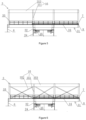
Figure 5 , the load-bearing system of the workingplatform 3 further includes avertical reinforcement structure 35. Thevertical reinforcement structure 35 includescolumns 351 and beams 353. Specifically, the number ofcolumns 351 is determined according to actual needs. The lower ends of thecolumns 351 are fixed on theplatform underframe 31, and beams 353 are horizontally fixed on thecolumns 351. Thecolumns 351 and thebeams 353 together with theplatform underframe 31 form a frame structure to ensure the strength and rigidity of theentire working platform 3, improve the bearing capacity, and reduce the deformation of the workingplatform 3 due to loads. - As shown in
Figure 6 , this embodiment is an improvement based onembodiment 1. In this embodiment, thevertical reinforcement structure 35 of the workingplatform 3 includescolumns 351, bracingsystem 352 and beams 353. Adjacent two columns 351 (also known as each span) are fixedly connected by bracingsystem 352 to improve the stress state of joints of beams and columns.Columns 351, bracingsystem 352 andbeams 353 together with theplatform underframe 31 form a braced frame structure to further increase the overall strength and rigidity of the workingplatform 3. - As shown in
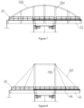
Figure 7 , in this embodiment, thevertical reinforcement structure 35 of the load-bearing system of the workingplatform 3 includestie rods 354 and an arch 355. Specifically, two ends of the arch 355 are fixedly connected to theplatform underframe 31, and thetie rods 354 are fixedly connected between the arch 355 and theplatform underframe 31. Thetie rods 354 are arranged along the length direction ofplatform underframe 31. Thetie rods 354 and the arch 355 together with theplatform underframe 31 form a self-stressed arch system to ensure the strength and rigidity of theentire working platform 3. By adopting this self-stressed arch-type bearing system, the bearing capacity of the workingplatform 3 can be improved and its deformation due to loads can be reduced. - As shown in
Figure 8 , in this embodiment, thevertical reinforcement structure 35 of the load-bearing system of the workingplatform 3 includes acable tower 356 andcables 357. Specifically, thecable tower 356 is fixed on theplatform underframe 31 and located near the middle ofplatform underframe 31.Cables 357 are multiple and their upper ends are fixedly connected to the top of thecable tower 356 while their lower ends are fixedly connected to different positions of theplatform underframe 31. Thecable tower 356 and thecables 357 together with theplatform underframe 31 form a cable-stayed structure to ensure the strength and rigidity of theentire working platform 3. By adopting this cable-stayed structure type bearing system, the bearing capacity of the workingplatform 3 can be improved and its deformation due to loads can be reduced. - As shown in
Figure 9 , in this embodiment, thevertical reinforcement structure 35 of the load-bearing system of the workingplatform 3 includesweb members 359 andupper chord members 358. Specifically,multiple web members 359 are set according to actual needs, including vertical setting and inclined setting. The lower ends of theweb members 359 are fixed on theplatform underframe 31 while theupper chord members 358 are horizontally fixed on theweb members 359. Theweb members 359 and theupper chord members 358 together with theplatform underframe 31 form a truss structure to ensure the strength and rigidity of theentire working platform 3. The bearing capacity of the workingplatform 3 can be improved and its deformation due to loads can be reduced. - Refer to
Figure 10 . This embodiment is basically similar toEmbodiment 1, but different in that theplatform underframe 31 of the workingplatform 3 sticks out of one side along the length direction of themonopile 1 for a long distance, and only slightly sticks out of the other side of themonopile 1, that is, the workingplatform 3 sticks out of one side only. This embodiment can be used in cases where the platform area does not need to be very large, reducing the structure of the workingplatform 3 and reducing the weight of the platform itself. However, higher technical requirements for the layout of theequipment 5 and thematerial bin 4 for construction are needed. - The rotating construction platform of the present disclosure uses the top of the
monopile 1 as a supporting foundation. With the increase of the diameter of the offshore monopile, the area of the pile top increases, which has sufficient rigidity and enhances the bearing capacity of the monopile. It can support a rotating platform stably and reliably. Through this rotating construction platform, construction around themonopile 1 can be effectively completed, such as pile foundation reinforcement (such as replacement method, high-pressure rotary spraying method, cement mixing method). It can replace the original method that requires offshore construction vessels or conventional temporary multi-pile platforms, reduce adverse effects such as tide level, waves and water current in marine environments, improve the continuity of construction operations, save construction time and costs, avoid vessel machinery from hitting themonopile 1 due to waves when the construction space is small, improve construction positioning accuracy and ensure construction quality. The rotating construction platform reduces the size of the platform under the premise of achieving the same construction scope, which brings convenience to construction and has practical engineering significance. - The rotating construction platform of the present disclosure can also be used for construction of anti-scouring facilities around the pile (sand quilt placement, stone throwing around the pile, artificial block throwing around the pile, solidified soil anti-scouring layer), installation of auxiliary facilities, anti-corrosion coating repair and other constructions. It can also be used as a temporary surveying, observation, and testing platform. In addition to being applied to offshore monopiles, based on the same or similar principles, it can also be applied to monopiles in water bodies such as lakes and rivers.
- In summary, the present disclosure effectively overcomes various disadvantages of the traditional technology and has high industrial application values.
- The above-mentioned embodiments are just used for exemplarily describing the principle and effects of the present disclosure instead of limiting the present disclosure. The invention is defined by the appended claims.
Claims (10)
- A rotating construction platform based on a monopile, comprising a rotary connecting mechanism (2) arranged on a top of the monopile (1) and a working platform (3) arranged on the rotary connecting mechanism (2), wherein the rotary connecting mechanism (2) comprises an upper connecting tube (22), a lower connecting tube (21), and a rotary support structure (23) located between the upper connecting tube (22) and the lower connecting tube (21), wherein the working platform (3) is fixedly connected to the upper connecting tube (22), and the lower connecting tube (21) is detachably fixed to the top of the monopile (1), wherein at least one side of the working platform (3) sticks out of a side of the monopile (1).
- The rotating construction platform according to claim 1, wherein the rotary connecting mechanism (2) further comprises a plurality of corbels (24) fixedly connected to the upper connecting tube (22), and the working platform (3) is fixedly connected to the plurality of corbels (24).
- The rotating construction platform according to claim 2, wherein a plurality of horizontal braces (25) is fixedly arranged between the plurality of corbels (24) and the upper connecting tube (22).
- The rotating construction platform according to claim 2, wherein a load-bearing system of the working platform (3) comprises a platform underframe (31), wherein the platform underframe (31) is fixedly connected with a plurality of short columns (32), wherein each of the plurality of short columns (32) is fixedly connected to one of the plurality of corbels (24) of the rotary connecting mechanism (2).
- The rotating construction platform according to claim 4, wherein the platform underframe (31) is rectangular and sticks out of one side or two sides of the monopile (1) along a length direction, wherein the platform underframe (31) comprises a plurality of main beams (312) arranged along the length direction, a plurality of secondary beams (313) arranged along a width direction, and a steel plate or grating (314) installed on the plurality of main beams (312) and the plurality of secondary beams (313), wherein the plurality of short columns (32) is fixedly connected with the plurality of main beams (312).
- The rotating construction platform according to claim 4, wherein the load-bearing system of the working platform (3) further comprises a vertical reinforcement structure (35) fixedly connected with the platform underframe (31).
- The rotating construction platform according to claim 6, wherein the load-bearing system of the working platform (3) including the platform underframe (31) and the vertical reinforcement structure (35) is a frame structure, a truss structure, a self-stressed arch system or a cable-stayed structure.
- The rotating construction platform according to claim 1, wherein the rotary connecting mechanism (2) further comprises a rotary control system for controlling the rotation of the rotary support structure (23).
- The rotating construction platform according to claim 1, wherein a berthing and boarding structure (6) is provided at a side of the working platform (3).
- The rotating construction platform according to claim 1, wherein the working platform (3) comprises a plurality of guardrails (33) and a plurality of wheel guard sills (34) installed on the platform underframe (31).
Applications Claiming Priority (3)
| Application Number | Priority Date | Filing Date | Title |
|---|---|---|---|
| CN202110484772.7A CN115262514B (en) | 2021-04-30 | 2021-04-30 | Rotary construction platform based on single pile foundation |
| CN202120946072.0U CN215518693U (en) | 2021-04-30 | 2021-04-30 | Rotary construction platform based on single pile foundation |
| PCT/CN2021/113820 WO2022227348A1 (en) | 2021-04-30 | 2021-08-20 | Rotating construction platform based on single pile foundation |
Publications (4)
| Publication Number | Publication Date |
|---|---|
| EP4321687A1 EP4321687A1 (en) | 2024-02-14 |
| EP4321687A4 EP4321687A4 (en) | 2024-10-02 |
| EP4321687B1 true EP4321687B1 (en) | 2025-06-11 |
| EP4321687C0 EP4321687C0 (en) | 2025-06-11 |
Family
ID=83847733
Family Applications (1)
| Application Number | Title | Priority Date | Filing Date |
|---|---|---|---|
| EP21938812.1A Active EP4321687B1 (en) | 2021-04-30 | 2021-08-20 | Rotating construction platform based on monopile |
Country Status (4)
| Country | Link |
|---|---|
| US (1) | US20240218625A1 (en) |
| EP (1) | EP4321687B1 (en) |
| BR (1) | BR112023022646A2 (en) |
| WO (1) | WO2022227348A1 (en) |
Family Cites Families (11)
| Publication number | Priority date | Publication date | Assignee | Title |
|---|---|---|---|---|
| US4943188A (en) * | 1988-05-20 | 1990-07-24 | Lockheed Corporation | Rotating lug anchor connector |
| GB2408767A (en) * | 2003-12-03 | 2005-06-08 | Slp Engineering Ltd | Method of constructing a piled offshore platform |
| BR112012006458A2 (en) * | 2009-09-25 | 2016-04-26 | Aker Subsea As | integrated production valve manifold and multiphase pump station |
| CN201746845U (en) * | 2010-04-02 | 2011-02-16 | 中国海洋石油总公司 | Pile foundation type foundation structure applicable to ocean engineering |
| DE102014220782A1 (en) * | 2014-10-14 | 2016-04-14 | Rwe Innogy Gmbh | Foundation system for the foundation of an offshore structure, procedure for the foundation of an offshore structure and offshore construction with an appropriate foundation system |
| CN104594317B (en) * | 2015-01-13 | 2017-05-10 | 江苏金风科技有限公司 | Working platform, single pile foundation, offshore working platform and installing method of offshore working platform |
| CN106978800A (en) * | 2017-03-22 | 2017-07-25 | 中国能源建设集团广东省电力设计研究院有限公司 | Offshore boosting station and its support meanss |
| IT201700032863A1 (en) * | 2017-03-24 | 2018-09-24 | Saipem Spa | Coupling system between a riser and a subsea support structure |
| WO2021034828A1 (en) * | 2019-08-19 | 2021-02-25 | Sofec, Inc. | Mooring systems and processes for using same |
| CN110422294B (en) * | 2019-08-23 | 2025-04-01 | 山东鼎盛精工股份有限公司 | A single-column moored wellhead production operation platform |
| NL2023942B1 (en) * | 2019-10-02 | 2021-06-11 | Spt Equipment Bv | Eccentric suction pile pump with hinged lift appliance. |
-
2021
- 2021-08-20 US US18/288,580 patent/US20240218625A1/en active Pending
- 2021-08-20 WO PCT/CN2021/113820 patent/WO2022227348A1/en not_active Ceased
- 2021-08-20 BR BR112023022646A patent/BR112023022646A2/en active IP Right Grant
- 2021-08-20 EP EP21938812.1A patent/EP4321687B1/en active Active
Also Published As
| Publication number | Publication date |
|---|---|
| WO2022227348A1 (en) | 2022-11-03 |
| BR112023022646A2 (en) | 2024-01-16 |
| EP4321687A1 (en) | 2024-02-14 |
| EP4321687A4 (en) | 2024-10-02 |
| EP4321687C0 (en) | 2025-06-11 |
| US20240218625A1 (en) | 2024-07-04 |
Similar Documents
| Publication | Publication Date | Title |
|---|---|---|
| EP1518053B1 (en) | Method and crane for installing, maintaining, and decommissioning wind turbines | |
| EP3904674B1 (en) | Floating platform for high-power wind turbines | |
| CN105603881B (en) | A kind of the integral erection system and its construction method of large-scale arch bridge over strait | |
| EP2837554A1 (en) | Partially floating marine platform for offshore wind-power, bridges and marine buildings, and construction method | |
| DE102010020995B4 (en) | Foundation system for the foundation of an offshore wind energy plant | |
| CN101949142B (en) | Long segmental structure of offshore high pile wharf | |
| CN205399220U (en) | Whole system of erectting of large -scale arched bridge over strait | |
| IL303559A (en) | Construction equipment and method for fully assembled superstructure of high piled wharf | |
| CN101792015B (en) | Multi-functional assembling type waterborne movable device | |
| CN103255752B (en) | Support the buoyant support fixed platform of offshore wind turbine, marine works | |
| DE102008029984A1 (en) | Buoyant assembly- and working platform for offshore-wind- and water turbines, has squad room and working areas process devices provided at board, and deck formed as helipad, where devices are provided with tanks or storage systems | |
| CN105603861A (en) | Integrated assembling floating transportation lifting arch bridge and construction method thereof | |
| DE102017115817A1 (en) | Foundation for an offshore wind energy plant | |
| CN114000459A (en) | Method for erecting platform for high-pile wharf cast-in-place pile construction | |
| CN215518693U (en) | Rotary construction platform based on single pile foundation | |
| EP2796713B1 (en) | Floating precast-concrete structure for supporting a wind turbine | |
| EP4314549A1 (en) | Foundation for an offshore wind turbine | |
| CN215518692U (en) | Construction platform device with hanging basket | |
| CN201915356U (en) | New pile wharf structure | |
| CN115262514B (en) | Rotary construction platform based on single pile foundation | |
| EP4321687A1 (en) | Rotating construction platform based on single pile foundation | |
| CN115262513B (en) | A construction platform device with hanging basket | |
| EP2634424B1 (en) | Method of constructing a foundation for tower-like structure | |
| CN220433648U (en) | Multifunctional pile stabilizing platform | |
| CN115787646B (en) | Aquatic temporary support construction device suitable for inland river |
Legal Events
| Date | Code | Title | Description |
|---|---|---|---|
| STAA | Information on the status of an ep patent application or granted ep patent |
Free format text: STATUS: THE INTERNATIONAL PUBLICATION HAS BEEN MADE |
|
| PUAI | Public reference made under article 153(3) epc to a published international application that has entered the european phase |
Free format text: ORIGINAL CODE: 0009012 |
|
| STAA | Information on the status of an ep patent application or granted ep patent |
Free format text: STATUS: REQUEST FOR EXAMINATION WAS MADE |
|
| 17P | Request for examination filed |
Effective date: 20231108 |
|
| AK | Designated contracting states |
Kind code of ref document: A1 Designated state(s): AL AT BE BG CH CY CZ DE DK EE ES FI FR GB GR HR HU IE IS IT LI LT LU LV MC MK MT NL NO PL PT RO RS SE SI SK SM TR |
|
| DAV | Request for validation of the european patent (deleted) | ||
| DAX | Request for extension of the european patent (deleted) | ||
| A4 | Supplementary search report drawn up and despatched |
Effective date: 20240902 |
|
| RIC1 | Information provided on ipc code assigned before grant |
Ipc: E02B 17/00 20060101AFI20240827BHEP |
|
| GRAP | Despatch of communication of intention to grant a patent |
Free format text: ORIGINAL CODE: EPIDOSNIGR1 |
|
| STAA | Information on the status of an ep patent application or granted ep patent |
Free format text: STATUS: GRANT OF PATENT IS INTENDED |
|
| INTG | Intention to grant announced |
Effective date: 20250120 |
|
| GRAS | Grant fee paid |
Free format text: ORIGINAL CODE: EPIDOSNIGR3 |
|
| GRAA | (expected) grant |
Free format text: ORIGINAL CODE: 0009210 |
|
| STAA | Information on the status of an ep patent application or granted ep patent |
Free format text: STATUS: THE PATENT HAS BEEN GRANTED |
|
| AK | Designated contracting states |
Kind code of ref document: B1 Designated state(s): AL AT BE BG CH CY CZ DE DK EE ES FI FR GB GR HR HU IE IS IT LI LT LU LV MC MK MT NL NO PL PT RO RS SE SI SK SM TR |
|
| REG | Reference to a national code |
Ref country code: GB Ref legal event code: FG4D |
|
| REG | Reference to a national code |
Ref country code: CH Ref legal event code: EP |
|
| REG | Reference to a national code |
Ref country code: IE Ref legal event code: FG4D |
|
| REG | Reference to a national code |
Ref country code: DE Ref legal event code: R096 Ref document number: 602021032297 Country of ref document: DE |
|
| U01 | Request for unitary effect filed |
Effective date: 20250630 |
|
| U07 | Unitary effect registered |
Designated state(s): AT BE BG DE DK EE FI FR IT LT LU LV MT NL PT RO SE SI Effective date: 20250704 |
|
| PG25 | Lapsed in a contracting state [announced via postgrant information from national office to epo] |
Ref country code: ES Free format text: LAPSE BECAUSE OF FAILURE TO SUBMIT A TRANSLATION OF THE DESCRIPTION OR TO PAY THE FEE WITHIN THE PRESCRIBED TIME-LIMIT Effective date: 20250611 |
|
| PG25 | Lapsed in a contracting state [announced via postgrant information from national office to epo] |
Ref country code: GR Free format text: LAPSE BECAUSE OF FAILURE TO SUBMIT A TRANSLATION OF THE DESCRIPTION OR TO PAY THE FEE WITHIN THE PRESCRIBED TIME-LIMIT Effective date: 20250912 Ref country code: NO Free format text: LAPSE BECAUSE OF FAILURE TO SUBMIT A TRANSLATION OF THE DESCRIPTION OR TO PAY THE FEE WITHIN THE PRESCRIBED TIME-LIMIT Effective date: 20250911 |
|
| PGFP | Annual fee paid to national office [announced via postgrant information from national office to epo] |
Ref country code: GB Payment date: 20250915 Year of fee payment: 5 |
|
| PG25 | Lapsed in a contracting state [announced via postgrant information from national office to epo] |
Ref country code: HR Free format text: LAPSE BECAUSE OF FAILURE TO SUBMIT A TRANSLATION OF THE DESCRIPTION OR TO PAY THE FEE WITHIN THE PRESCRIBED TIME-LIMIT Effective date: 20250611 |
|
| PG25 | Lapsed in a contracting state [announced via postgrant information from national office to epo] |
Ref country code: RS Free format text: LAPSE BECAUSE OF FAILURE TO SUBMIT A TRANSLATION OF THE DESCRIPTION OR TO PAY THE FEE WITHIN THE PRESCRIBED TIME-LIMIT Effective date: 20250911 |
|
| U20 | Renewal fee for the european patent with unitary effect paid |
Year of fee payment: 5 Effective date: 20250916 |
|
| PG25 | Lapsed in a contracting state [announced via postgrant information from national office to epo] |
Ref country code: IS Free format text: LAPSE BECAUSE OF FAILURE TO SUBMIT A TRANSLATION OF THE DESCRIPTION OR TO PAY THE FEE WITHIN THE PRESCRIBED TIME-LIMIT Effective date: 20251011 |
|
| PG25 | Lapsed in a contracting state [announced via postgrant information from national office to epo] |
Ref country code: SM Free format text: LAPSE BECAUSE OF FAILURE TO SUBMIT A TRANSLATION OF THE DESCRIPTION OR TO PAY THE FEE WITHIN THE PRESCRIBED TIME-LIMIT Effective date: 20250611 |
|
| PG25 | Lapsed in a contracting state [announced via postgrant information from national office to epo] |
Ref country code: CZ Free format text: LAPSE BECAUSE OF FAILURE TO SUBMIT A TRANSLATION OF THE DESCRIPTION OR TO PAY THE FEE WITHIN THE PRESCRIBED TIME-LIMIT Effective date: 20250611 |
|
| PG25 | Lapsed in a contracting state [announced via postgrant information from national office to epo] |
Ref country code: PL Free format text: LAPSE BECAUSE OF FAILURE TO SUBMIT A TRANSLATION OF THE DESCRIPTION OR TO PAY THE FEE WITHIN THE PRESCRIBED TIME-LIMIT Effective date: 20250611 |
|
| PG25 | Lapsed in a contracting state [announced via postgrant information from national office to epo] |
Ref country code: SK Free format text: LAPSE BECAUSE OF FAILURE TO SUBMIT A TRANSLATION OF THE DESCRIPTION OR TO PAY THE FEE WITHIN THE PRESCRIBED TIME-LIMIT Effective date: 20250611 |
|
| REG | Reference to a national code |
Ref country code: CH Ref legal event code: H13 Free format text: ST27 STATUS EVENT CODE: U-0-0-H10-H13 (AS PROVIDED BY THE NATIONAL OFFICE) Effective date: 20260324 |
|
| PG25 | Lapsed in a contracting state [announced via postgrant information from national office to epo] |
Ref country code: MC Free format text: LAPSE BECAUSE OF FAILURE TO SUBMIT A TRANSLATION OF THE DESCRIPTION OR TO PAY THE FEE WITHIN THE PRESCRIBED TIME-LIMIT Effective date: 20250611 |
|
| PLBE | No opposition filed within time limit |
Free format text: ORIGINAL CODE: 0009261 |
|
| STAA | Information on the status of an ep patent application or granted ep patent |
Free format text: STATUS: NO OPPOSITION FILED WITHIN TIME LIMIT |
|
| PG25 | Lapsed in a contracting state [announced via postgrant information from national office to epo] |
Ref country code: CH Free format text: LAPSE BECAUSE OF NON-PAYMENT OF DUE FEES Effective date: 20250831 |
|
| REG | Reference to a national code |
Ref country code: CH Ref legal event code: L10 Free format text: ST27 STATUS EVENT CODE: U-0-0-L10-L00 (AS PROVIDED BY THE NATIONAL OFFICE) Effective date: 20260423 |