EP4321434A1 - Passenger seat armrest assembly - Google Patents
Passenger seat armrest assembly Download PDFInfo
- Publication number
- EP4321434A1 EP4321434A1 EP23182993.8A EP23182993A EP4321434A1 EP 4321434 A1 EP4321434 A1 EP 4321434A1 EP 23182993 A EP23182993 A EP 23182993A EP 4321434 A1 EP4321434 A1 EP 4321434A1
- Authority
- EP
- European Patent Office
- Prior art keywords
- armrest
- assembly
- link
- front link
- primary
- Prior art date
- Legal status (The legal status is an assumption and is not a legal conclusion. Google has not performed a legal analysis and makes no representation as to the accuracy of the status listed.)
- Granted
Links
Images





Classifications
-
- B—PERFORMING OPERATIONS; TRANSPORTING
- B64—AIRCRAFT; AVIATION; COSMONAUTICS
- B64D—EQUIPMENT FOR FITTING IN OR TO AIRCRAFT; FLIGHT SUITS; PARACHUTES; ARRANGEMENT OR MOUNTING OF POWER PLANTS OR PROPULSION TRANSMISSIONS IN AIRCRAFT
- B64D11/00—Passenger or crew accommodation; Flight-deck installations not otherwise provided for
- B64D11/06—Arrangements of seats, or adaptations or details specially adapted for aircraft seats
- B64D11/0639—Arrangements of seats, or adaptations or details specially adapted for aircraft seats with features for adjustment or converting of seats
- B64D11/0644—Adjustable arm rests
-
- B—PERFORMING OPERATIONS; TRANSPORTING
- B60—VEHICLES IN GENERAL
- B60N—SEATS SPECIALLY ADAPTED FOR VEHICLES; VEHICLE PASSENGER ACCOMMODATION NOT OTHERWISE PROVIDED FOR
- B60N2/00—Seats specially adapted for vehicles; Arrangement or mounting of seats in vehicles
- B60N2/75—Arm-rests
- B60N2/753—Arm-rests movable to an inoperative position
-
- B—PERFORMING OPERATIONS; TRANSPORTING
- B60—VEHICLES IN GENERAL
- B60N—SEATS SPECIALLY ADAPTED FOR VEHICLES; VEHICLE PASSENGER ACCOMMODATION NOT OTHERWISE PROVIDED FOR
- B60N2/00—Seats specially adapted for vehicles; Arrangement or mounting of seats in vehicles
- B60N2/75—Arm-rests
- B60N2/763—Arm-rests adjustable
- B60N2/77—Height adjustment
-
- B—PERFORMING OPERATIONS; TRANSPORTING
- B60—VEHICLES IN GENERAL
- B60N—SEATS SPECIALLY ADAPTED FOR VEHICLES; VEHICLE PASSENGER ACCOMMODATION NOT OTHERWISE PROVIDED FOR
- B60N2/00—Seats specially adapted for vehicles; Arrangement or mounting of seats in vehicles
- B60N2/75—Arm-rests
- B60N2/763—Arm-rests adjustable
- B60N2/777—Transversal adjustment
Definitions
- the present disclosure relates to the field of armrests, and armrest assemblies used for manufacturing seat assemblies. More specifically, the present disclosure relates to the field of armrests, and armrest assemblies used for manufacturing seat assemblies for vehicles including aircraft.
- Seating designed to accommodate more than one person often includes a plurality of individual and separated, as well as adjoined seats, located next to one another.
- Such seating designed to accommodate a plurality of people often position armrests for convenience that can act as separators delineating the area of individual seats.
- a single adjoining armrest often exists to service the occupants of adjoining seats.
- the armrest located between adjoining passengers must be shared if the armrest is to be used by both passengers.
- Such a shared armrest called upon to concurrently service adjoining passengers has been found to inadequately serve the needs of adjoining passengers.
- the primary armrest assembly includes a primary armrest assembly first surface (e.g., an upper surface) and a primary armrest assembly secondary (lower) surface (e.g., a lower surface), with the primary armrest assembly comprising a primary armrest proximal end and a primary armrest distal end, with the primary armrest proximal end in communication with a seat assembly.
- the armrest assembly further includes a secondary armrest assembly, with the secondary armrest assembly including a secondary armrest front link.
- the secondary armrest front link includes a secondary armrest front link first surface (e.g., an upper surface) and a secondary armrest front link second surface (e.g., a lower surface), with the secondary armrest front link further including a secondary armrest front link proximal end and a secondary armrest front link distal end.
- the secondary armrest front link proximal end includes a secondary armrest front link proximal end flange, and the secondary armrest front link proximal end flange includes a secondary armrest front link proximal end flange through opening.
- the secondary armrest assembly further includes a secondary armrest intermediate link, with the secondary armrest intermediate link including a secondary armrest intermediate link proximal end and a secondary armrest intermediate link distal end, and with the secondary armrest intermediate link distal end including a secondary armrest intermediate link distal end flange configured to movably and pivotably engage the secondary armrest front link proximal end flange.
- the armrest assembly further includes an armrest assembly end link, with the armrest assembly end link including an armrest assembly end link proximal end and an armrest assembly end link distal end, and with the armrest assembly end link distal end configured to movably and pivotably engage the secondary armrest intermediate link proximal end flange, and with the armrest assembly end link proximal end configured to engage or otherwise be in communication with at least one of a seat frame, a seat assembly component, and a seat assembly.
- the secondary armrest assembly is configured to move from a secondary armrest assembly stowed position located immediately beneath the primary armrest assembly and within a dimensional footprint of the primary armrest assembly, to a secondary armrest assembly deployed position located laterally adjacent to the primary armrest assembly (e.g.. the secondary armrest assembly in the deployed position is moved "out from under" the primary armrest assembly, and outside of or beyond the dimensional footprint of the primary armrest assembly such that the secondary armrest assembly is exposed.
- the primary armrest assembly has a first average width (W1) along a longitudinal axis of the primary armrest assembly
- the secondary armrest front link has a second average width (W2) along a longitudinal axis of the secondary armrest assembly, with the first average width (W1) greater than or equal to the second average width (W2).
- the secondary armrest assembly in the stowed position is configured to movably nest beneath and immediately adjacent to the primary armrest assembly.
- the secondary armrest assembly further includes a secondary armrest front link length extender, with the secondary armrest front link length extender configured to extend outwardly to a selected extended distance from the secondary armrest front link distal end.
- the secondary armrest front link length extender can be an extendable nested member that can extend from and retract to a secondary armrest front link length extender first position in the secondary armrest assembly to a secondary armrest front link length extender second position in the secondary armrest assembly.
- the secondary armrest front link first surface comprises a secondary armrest front link first surface area, and wherein the entirety of the secondary armrest front link first surface area is exposed in the secondary armrest assembly deployed position.
- the secondary armrest front link first surface includes a secondary armrest cushion layer first section, with the intermediate link including a secondary armrest cushion layer second section, and with the primary armrest assembly first surface including a primary armrest assembly cushion layer.
- the secondary armrest cushion layer first section is positioned at a secondary armrest cushion layer first section relative height, with the secondary armrest cushion layer first section relative height varying from a primary armrest assembly cushion layer relative height.
- the intermediate link proximal end is configured to movably engage with the end link distal end, and with the intermediate link configured to movably pivot horizontally about the end link distal end.
- the secondary armrest front link proximal end is configured to movably and pivotably engage with the intermediate link distal end, with the secondary armrest front link further configured to movably pivot horizontally about the intermediate link distal end.
- a further example is directed to a seat assembly, with the seat assembly including an armrest assembly, with the armrest assembly including a primary armrest assembly including a primary armrest assembly first surface (e.g., an upper surface) and a primary armrest assembly second (lower) surface (e.g., a lower surface), with the primary armrest assembly further including a primary armrest proximal end and a primary armrest distal end.
- the armrest assembly further includes a secondary armrest assembly, with the secondary armrest assembly including a secondary armrest front link.
- the secondary armrest front link includes a secondary armrest front link first surface (e.g., an upper surface) and a secondary armrest front link second surface (e.g., a lower surface), with the secondary armrest front link including a secondary armrest front link proximal end and a secondary armrest front link distal end.
- the secondary armrest front link proximal end includes a secondary armrest front link proximal end flange, and the secondary armrest front link proximal end flange includes a secondary armrest front link proximal end flange through opening.
- the secondary armrest assembly further includes a secondary armrest intermediate link, with the secondary armrest intermediate link including a secondary armrest intermediate link proximal end and a secondary armrest intermediate link distal end, and with the secondary armrest intermediate link distal end including a secondary armrest intermediate link distal end flange configured to movably engage the secondary armrest front link proximal end flange.
- the armrest assembly further includes an armrest assembly end link, with the armrest assembly end link including an armrest assembly end link proximal end and an armrest assembly end link distal end, and with the armrest assembly end link distal end configured to movably engage the secondary armrest intermediate link proximal end flange, and with the armrest assembly end link proximal end configured to engage at least one of a seat frame, a seat frame component, and a seat assembly.
- the passenger vehicle including the presently disclosed armrest assemblies is selected from the group consisting of a crewed aircraft, an uncrewed aircraft, a crewed spacecraft, an uncrewed spacecraft, a crewed rotorcraft, an uncrewed rotorcraft, a crewed terrestrial vehicle, an uncrewed terrestrial vehicle; a crewed surface water borne vehicle, an uncrewed waterborne vehicle, a crewed sub-surface water borne vehicle, an uncrewed sub-surface water borne vehicle, and combinations thereof.
- Still further examples are directed to aircraft, that can include passenger aircraft comprising the presently disclosed armrest assemblies.
- Still further examples are directed to aircraft, that can include passenger aircraft comprising the presently disclosed seating assemblies
- a secondary armrest assembly is presently disclosed, with the secondary armrest assembly including a secondary armrest front link, and with the secondary armrest front link comprising a secondary armrest front link first surface (e.g., secondary armrest front link upper surface) and a secondary armrest front link second surface (e.g., secondary armrest front link lower surface), with the secondary armrest front link including a secondary armrest front link proximal end and a secondary armrest front link distal end, and with the secondary armrest front link proximal end comprising a secondary armrest front link proximal end flange, and with the secondary armrest front link proximal end flange comprising a secondary armrest front link proximal end flange through opening.
- the secondary armrest assembly including a secondary armrest front link
- the secondary armrest front link comprising a secondary armrest front link first surface (e.g., secondary armrest front link upper surface) and a secondary armrest front link second surface (e.g., secondary armrest front link lower surface
- the secondary armrest assembly further includes a secondary armrest intermediate link, with the secondary armrest intermediate link including a secondary armrest intermediate link proximal end and a secondary armrest intermediate link distal end, with the secondary armrest intermediate link distal end including a secondary armrest intermediate link distal end flange configured to movably and pivotably engage the secondary armrest front link proximal end flange.
- the secondary armrest assembly is configured to move from a secondary armrest assembly stowed position to a secondary armrest assembly deployed position.
- the secondary armrest assembly is in communication with an armrest assembly end link, with the armrest assembly end link including an armrest assembly end link proximal end and an armrest assembly end link distal end, with the armrest assembly end link distal end configured to movably and pivotably engage the secondary armrest intermediate link proximal end flange, and with the armrest assembly end link proximal end configured to engage at least one of a seat frame, a seat frame component, and a seat assembly.
- the secondary armrest assembly in the stowed position is configured and dimensioned to movably and/or pivotably nest beneath a primary armrest assembly.
- the secondary armrest assembly further includes a secondary armrest front link extender, with the secondary armrest front link extender configured to extend to a selected distance outwardly from the secondary armrest front link distal end in an extended configuration that is different from and great than secondary armrest front link extender initial position (e.g., a non-extended position) along the longitudinal axis of the secondary armrest assembly.
- a secondary armrest front link extender configured to extend to a selected distance outwardly from the secondary armrest front link distal end in an extended configuration that is different from and great than secondary armrest front link extender initial position (e.g., a non-extended position) along the longitudinal axis of the secondary armrest assembly.
- the secondary armrest front link is configured to extend vertically to a selected height in a secondary armrest front link vertically extended configuration, with the selected height in a secondary armrest front link vertically extended configuration different than a secondary armrest front link height in the secondary armrest assembly stowed configuration.
- Another example is directed to a passenger vehicle including the seat assembly comprising the secondary armrest assembly disclosed herein, with the passenger vehicle selected from the group consisting of a crewed aircraft, an uncrewed aircraft, a crewed spacecraft, an uncrewed spacecraft, a crewed rotorcraft, an uncrewed rotorcraft, a crewed terrestrial vehicle, an uncrewed terrestrial vehicle; a crewed surface water borne vehicle, an uncrewed waterborne vehicle, a crewed sub-surface water borne vehicle, an uncrewed sub-surface water borne vehicle, and combinations thereof.
- Another example is directed to an aircraft comprising the seat assembly comprising the secondary armrest assembly disclosed herein.
- a method for installing an armrest assembly into a seat assembly comprising providing a seat assembly comprising a seat assembly frame, with the seat assembly frame configured to support a plurality of seats, and attaching an armrest assembly to the seat assembly frame, with the armrest assembly comprising a secondary armrest front link, with the secondary armrest front link comprising a secondary armrest front link first surface (e.g., secondary armrest front link upper surface) and a secondary armrest front link second surface (e.g., secondary armrest front link lower surface), with the secondary armrest front link including a secondary armrest front link proximal end and a secondary armrest front link distal end, and with the secondary armrest front link proximal end comprising a secondary armrest front link proximal end flange, and with the secondary armrest front link proximal end flange comprising a secondary armrest front link proximal end flange through opening.
- the secondary armrest front link proximal end flange comprising a secondary armrest front link prox
- the secondary armrest assembly further includes a secondary armrest intermediate link, with the secondary armrest intermediate link including a secondary armrest intermediate link proximal end and a secondary armrest intermediate link distal end, with the secondary armrest intermediate link distal end including a secondary armrest intermediate link distal end flange configured to movably and pivotably engage the secondary armrest proximal end flange, wherein the secondary armrest assembly is attached to the seat frame via an armrest assembly end link, with the armrest assembly end link comprising an armrest assembly end link proximal end and an armrest assembly end link distal end, with the armrest assembly end link distal end configured to movably engage the armrest assembly intermediate link proximal end flange, and with the armrest assembly end link proximal end configured to engage at least one of a seat assembly frame, a seat frame component, and a seat assembly.
- the method further comprises attaching a primary armrest assembly to the armrest assembly end link, with the primary armrest assembly comprising a primary armrest assembly first surface (e.g., a primary armrest assembly upper surface) and a primary armrest assembly second surface (e.g., a primary armrest assembly lower surface), with the primary armrest assembly comprising a primary armrest proximal end and a primary armrest distal end, with the primary armrest distal end, and with the primary armrest distal end configured to engage the armrest assembly end link.
- the primary armrest assembly comprising a primary armrest assembly first surface (e.g., a primary armrest assembly upper surface) and a primary armrest assembly second surface (e.g., a primary armrest assembly lower surface)
- the primary armrest assembly comprising a primary armrest proximal end and a primary armrest distal end, with the primary armrest distal end, and with the primary armrest distal end configured to engage the armrest assembly end link.
- the method further comprises nesting the secondary armrest assembly beneath the primary armrest assembly in a secondary armrest assembly stowed configuration.
- a method for installing a seat assembly into a passenger aircraft comprising installing a seat assembly into a passenger vehicle, with the seat assembly comprising an armrest assembly, and with the armrest assembly comprising a primary armrest assembly.
- the primary armrest assembly includes a primary armrest assembly first (upper) surface and a primary armrest assembly second (lower) surface, with the primary armrest assembly comprising a primary armrest proximal end and a primary armrest distal end.
- the armrest assembly further comprises a secondary armrest assembly, with the secondary armrest assembly comprising a secondary armrest front link, with the secondary armrest front link comprising a secondary armrest front link first (upper) surface and a secondary armrest front link second (lower) surface.
- the secondary armrest front link comprises a secondary armrest front link proximal end and a secondary armrest front link distal end, with the secondary armrest front link proximal end comprising a secondary armrest front link proximal end flange, with the secondary armrest front link proximal end flange comprising a secondary armrest front link proximal end flange through opening, and with the secondary armrest assembly further comprising a secondary armrest intermediate link.
- the secondary armrest intermediate link comprises a secondary armrest intermediate link proximal end and a secondary armrest intermediate link distal end, with the secondary armrest intermediate link distal end comprising a secondary armrest intermediate link distal end flange configured to movably and pivotably engage the secondary armrest front link proximal end flange.
- the secondary armrest assembly further comprises an armrest assembly end link, with the armrest assembly end link comprising an armrest assembly end link proximal end and an armrest assembly end link distal end, with the armrest assembly end link distal end configured to movably engage the secondary armrest intermediate link proximal end flange, and with the armrest assembly end link proximal end configured to engage at least one of a seat assembly frame, a seat frame component, and a seat assembly seat frame.
- An example provides armrest assembly comprising: a primary armrest assembly.
- the primary armrest assembly comprises: a primary armrest first (upper) surface and a primary armrest second (lower) surface, the primary armrest comprising a primary armrest proximal end and a primary armrest distal end, the primary armrest proximal end in communication with a seat assembly.
- the armrest assembly further comprises a secondary armrest assembly comprising: a secondary armrest front link, the secondary armrest front link comprising a secondary armrest front link first (upper) surface, a secondary armrest front link second (lower) surface, a secondary armrest front link proximal end and a secondary armrest front link distal end.
- the secondary armrest front link proximal end comprises a secondary armrest front link proximal end flange, the secondary armrest front link proximal end comprising a secondary front link proximal end flange; or the secondary armrest front link proximal end comprises a secondary armrest front link proximal end flange, the secondary armrest front link proximal end flange comprising a secondary front link proximal end flange through opening.
- the secondary armrest assembly further comprises a secondary armrest intermediate link, the secondary armrest intermediate link comprising a secondary armrest intermediate link proximal end comprising a secondary armrest intermediate proximal end flange, and a secondary armrest intermediate link distal end.
- the secondary armrest intermediate link distal end comprises at least one intermediate link distal end flange configured to movably and pivotably engage the secondary armrest front link proximal flange.
- the armrest assembly further comprises an armrest assembly end link comprising an armrest assembly end link proximal end comprising an armrest assembly end link proximal end flange, the armrest assembly end link further comprising an armrest assembly end link distal end comprising an armrest assembly end link distal end flange.
- the armrest assembly end link distal end is configured to movably and pivotable engage the intermediate link proximal end flange, the armrest assembly end link proximal end configured to engage at least one of a seat frame and the seat assembly.
- the secondary armrest assembly is configured to move from a secondary armrest assembly stowed position immediately beneath the primary armrest assembly, and within a dimensional footprint of the primary armrest assembly, to a secondary armrest assembly deployed position laterally adjacent to the primary armrest assembly.
- the secondary armrest assembly in the secondary armrest assembly stowed position is configured to movably nest beneath the primary armrest assembly.
- the secondary armrest assembly further comprises a secondary armrest front link length extender, the secondary armrest front link length extender configured to extend outwardly to a selected extended distance from the secondary armrest front link distal end.
- the primary armrest assembly has a first average width perpendicular to a primary armrest longitudinal axis
- the secondary armrest front link has a second average width perpendicular to a secondary armrest front link longitudinal axis, the first average width greater than or equal to the second average width
- the secondary armrest front link first surface comprises a secondary armrest front link first surface area, and wherein the entirety of the secondary armrest front link first surface area is exposed in the secondary armrest assembly deployed position.
- the secondary armrest front link first surface comprises a secondary armrest cushion layer first section
- the secondary armrest intermediate link comprises a secondary armrest cushion layer second section
- the primary armrest first surface comprises a primary armrest assembly cushion layer.
- the secondary armrest front link is positioned at a secondary armrest front link average height, the secondary armrest front link average height varying from a primary armrest assembly average height.
- the secondary armrest intermediate link proximal end flange is configured to movably engage with the armrest assembly end link distal end, the secondary armrest intermediate link configured to movably pivot about the armrest assembly end link distal end.
- the secondary armrest front link proximal end flange is configured to movably engage with the secondary armrest intermediate link distal end, the secondary armrest front link proximal end further configured to movably pivot about the secondary armrest intermediate link distal end.
- Another example provides a seat assembly comprising any of the armrest assemblies described above.
- a passenger vehicle comprising any of the armrest assemblies described above.
- the passenger vehicle is selected from the group consisting of: a crewed aircraft, an uncrewed aircraft, a crewed spacecraft, an uncrewed spacecraft, a crewed rotorcraft, an uncrewed rotorcraft, a crewed terrestrial vehicle, an uncrewed terrestrial vehicle; a crewed surface water borne vehicle, an uncrewed waterborne vehicle, a crewed sub-surface water borne vehicle, an uncrewed sub-surface water borne vehicle, a satellite, and combinations thereof.
- Another example provides an aircraft comprising any of the armrest assemblies described above.
- a secondary armrest assembly comprising: a secondary armrest front link, the secondary armrest front link comprising a secondary armrest front link first (upper) surface and a secondary armrest front link second (lower) surface, the secondary armrest front link comprising a secondary armrest front link proximal end and a secondary armrest front link distal end, the second armrest front link proximal end comprising a second armrest front link proximal end flange, the second armrest front link proximal end flange comprising a second armrest front link proximal end flange through opening.
- the secondary armrest assembly further comprises a secondary armrest intermediate link, the secondary armrest intermediate link comprising a secondary armrest intermediate link proximal end and a secondary armrest intermediate link distal end, the secondary armrest intermediate link distal end comprising a secondary armrest intermediate link distal end flange configured to receive and maintain a secondary armrest intermediate link distal end pin, and the secondary armrest intermediate link distal end flange configured to movably and pivotably engage the secondary armrest front link proximal end flange.
- the secondary armrest assembly is configured to move from a secondary armrest assembly stowed position beneath a primary armrest assembly to a secondary armrest assembly deployed position.
- the secondary armrest assembly is in communication with an armrest assembly end link, the armrest assembly end link comprising an armrest assembly end link proximal end and an armrest assembly end link distal end, the armrest assembly end link distal end configured to movably and pivotably engage the secondary armrest intermediate link proximal end flange, the secondary armrest end link proximal end configured to engage at least one of a seat frame and a seat frame assembly.
- the secondary armrest assembly in the secondary armrest assembly stowed position is configured and dimensioned to movably nest beneath the primary armrest assembly.
- the secondary armrest assembly further comprises a secondary armrest front link extender, the secondary armrest front link extender configured to extend distally outward a selected distance from the secondary armrest front link distal end along a secondary armrest front link longitudinal axis.
- the secondary armrest assembly front link first surface comprises a secondary armrest cushion first section
- the secondary armrest intermediate link comprises a secondary armrest cushion second section.
- the secondary armrest intermediate link proximal end is configured to movably engage with the armrest assembly end link distal end, the secondary armrest intermediate link configured to movably pivot about the armrest assembly end link distal end.
- the secondary armrest front link proximal end is configured to movably engage with the secondary armrest intermediate link distal end, the secondary armrest front link proximal end further configured to movably pivot about the secondary armrest intermediate link distal end.
- the secondary armrest front link configured to extend vertically from the secondary armrest assembly to a selected height.
- Another example provides a seat assembly comprising any of the secondary armrest assemblies described above.
- a passenger vehicle comprising any of the secondary armrest assemblies described above.
- the passenger vehicle is selected from the group consisting of: a crewed aircraft, an uncrewed aircraft, a crewed spacecraft, an uncrewed spacecraft, a crewed rotorcraft, an uncrewed rotorcraft, a crewed terrestrial vehicle, an uncrewed terrestrial vehicle; a crewed surface water borne vehicle, an uncrewed waterborne vehicle, a crewed sub-surface water borne vehicle, an uncrewed sub-surface water borne vehicle, a satellite, and combinations thereof.
- Another example provides an aircraft comprising any of the secondary armrest assemblies described above.
- Another example provides a method for installing an armrest assembly into a seat assembly, the method comprising: providing a seat assembly, the seat assembly comprising a seat assembly frame.
- the method further comprises attaching a secondary armrest assembly to at least one of the seat assembly and the seat assembly frame, the secondary armrest assembly comprising: a secondary armrest front link, the secondary armrest front link comprising a secondary armrest front link first (upper) surface and a secondary armrest front link second (lower) surface, the secondary armrest front link further comprising a secondary armrest front link proximal end and a secondary armrest front link distal end, the second armrest front link proximal end comprising a second armrest front link proximal end flange, the second armrest front link proximal end flange comprising a second armrest front link proximal end flange through opening; and a secondary armrest intermediate link, the secondary armrest intermediate link comprising a secondary armrest intermediate link proximal end and a secondary armrest intermediate link distal
- the secondary armrest assembly is attached to the at least one of the seat assembly and the seat assembly frame via an armrest assembly end link, the armrest assembly end link comprising an armrest assembly end link proximal end and an armrest assembly end link distal end, the armrest assembly end link distal end configured to movably engage the secondary armrest intermediate link proximal end flange, the armrest assembly end link proximal end configured to engage the at least one of the seat assembly and the seat assembly frame.
- the method further comprises: attaching a primary armrest assembly to the armrest assembly end link, the primary armrest assembly comprising a primary armrest assembly first (upper) surface and a primary armrest assembly second (lower) surface, the primary armrest assembly comprising a primary armrest proximal end and a primary armrest distal end, the primary armrest distal end configured to engage the armrest assembly end link.
- the method further comprises: nesting the secondary armrest assembly beneath the primary armrest assembly in a secondary armrest assembly stowed configuration.
- Another example provides a method for installing a seat assembly into a passenger vehicle, the method comprising: installing a seat assembly into a passenger vehicle, the seat assembly comprising an armrest assembly.
- the armrest assembly comprises: a primary armrest assembly, the primary armrest assembly comprising a primary armrest assembly first (upper) surface and a primary armrest assembly second (lower) surface.
- the primary armrest assembly further comprises a primary armrest proximal end and a primary armrest distal end.
- the seat assembly further comprises a secondary armrest assembly, the secondary armrest assembly comprising a secondary armrest front link, the secondary armrest front link comprising a second armrest front link first (upper) surface and a secondary armrest front link second (lower) surface, the secondary armrest front link further comprising a secondary armrest front link proximal end and a secondary armrest front link distal end, the second armrest front link proximal end comprising a second armrest front link proximal end flange, the second armrest front link proximal end flange comprising a second armrest front link proximal end flange through opening.
- the second armrest assembly further comprises: a secondary armrest intermediate link, the secondary armrest intermediate link comprising a secondary armrest intermediate link proximal end and an intermediate link distal end, the intermediate link distal end comprising an intermediate link distal end flange configured to movably engage the secondary armrest front link proximal end flange.
- the armrest assembly further comprises an armrest assembly end link, the armrest assembly end link comprising an armrest assembly end link proximal end and an armrest assembly end link distal end, the armrest assembly end link distal end configured to movably engage the secondary armrest intermediate link proximal end flange, the armrest assembly end link proximal end configured to engage at least one of the seat assembly and a seat assembly frame.
- the passenger vehicle is selected from the group consisting of: a crewed aircraft, an uncrewed aircraft, a crewed spacecraft, an uncrewed spacecraft, a crewed rotorcraft, an uncrewed rotorcraft, a crewed terrestrial vehicle, an uncrewed terrestrial vehicle; a crewed surface water borne vehicle, an uncrewed waterborne vehicle, a crewed sub-surface water borne vehicle, an uncrewed sub-surface water borne vehicle, a satellite, and combinations thereof.
- the passenger vehicle is an aircraft.
- an armrest assembly having a primary armrest and a secondary armrest assembly that can be stowed beneath the primary armrest in a nested configuration beneath the primary armrest.
- the secondary armrest can be manipulated from a stowed configuration beneath the primary armrest to a deployed configuration that exposes the secondary armrest and positions the secondary armrest to a deployed position that is laterally adjacent to the primary armrest.
- the height of the secondary armrest, when deployed, can be adjusted by vertically raising the secondary armrest to a height that is lower than, equivalent to, or higher than the height of the primary armrest that may be a fixed primary armrest height.
- the secondary armrest comprises a secondary armrest assembly that comprises a plurality of moving parts that together facilitated a manipulated and articulated movement of the secondary armrest from a secondary armrest stowed position beneath a primary armrest to a secondary armrest deployed position where the secondary armrest assembly is positioned adjacent to the primary armrest.
- the presently disclosed armrest assemblies can be installed into seat assemblies within a seat assembly frame that can support a plurality of adjacently positioned seats within the seat assembly frame.
- the seating assemblies disclosed herein can stand alone and be positioned in areas designed to seat occupants including, for example, waiting areas, theaters, lecture halls, etc.
- the seating assemblies disclosed herein can also be incorporated into larger structures including vehicles that can further include, for example, passenger vehicles such as, for example, cars, busses, trains, boats, aircraft, etc.
- the presently disclosed seating assemblies comprising the presently disclosed armrest assemblies can find utility installed into vehicles including passenger vehicles such as, for example, a crewed aircraft, an uncrewed aircraft, a crewed spacecraft, an uncrewed spacecraft, a crewed rotorcraft, an uncrewed rotorcraft, a crewed terrestrial vehicle, an uncrewed terrestrial vehicle; a crewed surface water borne vehicle, an uncrewed waterborne vehicle, a crewed sub-surface water borne vehicle, an uncrewed sub-surface water borne vehicle, and combinations thereof.
- passenger vehicles such as, for example, a crewed aircraft, an uncrewed aircraft, a crewed spacecraft, an uncrewed spacecraft, a crewed rotorcraft, an uncrewed rotorcraft, a crewed terrestrial vehicle, an uncrewed terrestrial vehicle; a crewed surface water borne vehicle, an uncrewed waterborne vehicle, a crewed sub-surface water borne vehicle
- FIG. 1 is an illustration of a vehicle in the form of an aircraft, according to present examples.
- aircraft 10 includes fuselage 12.
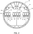
- FIG. 2 is a cross-sectional view of aircraft 10 shown in FIG. 1 and taken across line "A-A", as also shown in FIG. 1 .
- FIG. 2 shows a view into an aircraft cabin 14 of aircraft 10, with the aircraft bounded by the interior of fuselage 12 and assemblies that may be attached to the interior of fuselage 12.
- FIG. 2 further illustrates seat assemblies 16 positioned throughout the cabin in a selected seating orientation, with the seating assemblies 16 comprising seat assembly frames 17 (seat assembly frames 17 also shown in FIGs.
- Seat assemblies 16 are further shown comprising individual seats 16a, 16b, 16c that are positioned in an adjoining configuration within the seat assembly 16.
- seats 16a, 16b, 16c are occupied by, for example, a passenger, a passenger seated in one of seats 16a, 16b, 16c would have at least theoretical access to two armrests, with one of the armrests being an armrest assembly 18 positioned between adjoining seats (e.g., positioned between seats 16a and 16b; positioned between 16b and 16c).
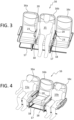
- FIGs. 3 and 4 are slightly elevated and enlarged front views of a seat assembly 16 comprising adjoined seats 16a, 16b, and 16c, with seat assembly 16 further comprising seat assembly frame 17 that is configured to fixedly attach seat assembly 16 in a fixed position (within, for example, an aircraft cabin) to a structural component or structural assembly (not shown in FIGs. 3 or 4 ).
- FIG. 3 shows a passenger 15 (drawn as an outline) representing a passenger seated in seat 16b.
- passenger 15 seated in seat 16b has an arm placed on an armrest assembly 18.
- FIG. 4 shows passengers 15a and 15b (drawn as an outline) representing a passenger seated in seats 16a and 16c, respectively.
- passengers 15a and 15b each have arms placed upon armrest assemblies 18 seated in seat 16b has an arm placed on a primary armrest 20 of armrest assembly 18.
- FIG. 4 is a slightly elevated and enlarged front view of a seat assembly 16 comprising adjoined seats 16a, 16b, and 16c, with seat assembly 16 further comprising seat assembly frame 17 that is configured to fixedly attach seat assembly 16 in a fixed position (within, for example, an aircraft cabin) to a structural component or structural assembly (not shown in FIGs. 3 or 4).
- FIG. 3 further shows a passenger 15 (drawn as an outline) representing a passenger seated in seat 16b. As shown in FIG. 3 , passenger 15 seated in seat 16b has an arm placed on a primary armrest 20 of an armrest assembly 18.
- armrest assemblies 18 that are positioned between adjacent and/or adjoining seats can be movably and pivotably attached (e.g., configured to facilitate a vertically pivoting motion about a fixed point that can be, for example, a pin), or are otherwise in movable and pivotable communication with seat assembly 16 and/or seat assembly frame 17, or another seat assembly component, etc., with armrest assemblies 18 configured to move and pivot from a deployed horizontal (or substantially horizontal) position ready for use (e.g., by a seated passenger), to a retracted and stowed position that can be a vertical (or substantially vertical) stowed position between adjacent seats, and that can be coincident with a positioning of the armrest assembly between adjacent/adjoining seat backs of seats in a seat assembly of the type shown and described herein.
- passengers 15a and 15b are not sitting in adjoining seats. Accordingly, passengers 15a and 15b would not be sharing an adjoining armrest between them as they otherwise might be forced to do if they were seated immediately adjacent to one another (e.g., in adjoining seats, etc.).
- armrest assembly 18 is shown in further detail with passenger 15 having arms on a primary armrest 20 of armrest assembly 18.
- FIG. 3 further shows secondary armrest assembly 23 deployed into a deployed position from a stowed position (e.g., a "nested" position) beneath primary armrest 20 of armrest assembly 18. In the stowed or “nested” configuration, the secondary armrest assembly 23 is in significant alignment with, and beneath, the primary armrest 20 of armrest assembly 18.
- a stowed position e.g., a "nested” position
- such dimensional footprint of the secondary armrest assembly (and particularly the secondary armrest front link) is configured to nest beneath and be completely covered by dimensional footprint (e.g., the surface area, etc.) of the primary armrest 20 when the secondary armrest assembly 23 is in the stowed configuration, and stowed beneath the primary armrest 20.
- armrest assembly 18 can be configured to deploy the secondary armrest assembly 23 from beneath primary armrest 20 such that a passenger adjoining passenger 15 would have access to an armrest (the secondary armrest assembly 23) dedicated to that adjoining passenger, without interfering with the ability of the adjoining passenger 15 to support the arms of adjoining passenger 15. That is, whatever dimensional surface footprint the upper surface (e.g.
- such dimensional footprint of the secondary armrest assembly (and particularly the secondary armrest front link) is configured to be deployed from the nested stowed configuration, exposing the secondary armrest assembly 23, and at least exposing the secondary armrest front link from beneath the primary armrest 20, such that the secondary armrest assembly 23 in the deployed configuration is not in alignment with the primary armrest 20 and, instead, is accessible as a dedicated armrest for use by an adjacently seated passenger.
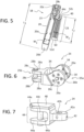
- FIG. 5 is an enlarged and partially exposed overhead plan view of an armrest assembly 18 according to present examples, and with armrest assembly 18 comprising an exposed view of a primary armrest 20 and a secondary armrest assembly 23 (in a deployed configuration) that comprises a secondary armrest front link 50 that is in articulable and pivotably movable communication with a secondary armrest intermediate link 40 about, for example, a secondary armrest intermediate distal end pin 44c, according to present examples.
- the secondary armrest intermediate link 40 is, in turn, in articulable and pivotably movable communication with armrest assembly end link 24 about armrest assembly end link distal end pin 28c (also referred to equivalently herein as "armrest assembly end link distal end flange pin 28c").
- the secondary armrest front link 50 in combination with the secondary armrest intermediate link 40 and the armrest assembly end link 24 can together comprise, in a three-component assembly, the secondary armrest assembly 23.
- the armrest assembly end link can comprise a distal end that can be attached to or otherwise in communication with a component of the seat assembly that can be, for example, a section of the seat assembly frame, adjoining/adjacent seat backs, other seat assembly structural components, etc.
- a seat assembly, seat assembly component, seat frame, etc. can incorporate a component similar in function to the assembly end link 24.
- the secondary armrest front link 50 in combination with the secondary armrest intermediate link 40 can together comprise, in a two-component assembly, the secondary armrest assembly 23 that will movably and pivotably engage with the integral feature of the seat assembly, seat assembly component, seat frame, etc., that performs the function of the armrest assembly end link 24 shown in the presently disclosed three-component armrest assemblies.
- FIG. 5 further shows comparative dimensions (e.g., “length (L1, L2) and “width” (W1, W2)) of the primary armrest 20 in comparison with the secondary armrest assembly 23 comprising the secondary armrest front link 50.
- the primary armrest 20 comprises a length, "L1" that extends from the primary armrest proximal end 20c to the primary armrest distal end 20d.
- the portion of the secondary armrest assembly 23 that can movably pivot about armrest assembly end link 23 and movably pivot out from a stowed position beneath primary armrest 20 to a secondary armrest deployed position (exposing secondary armrest front link 50 and secondary armrest intermediate link 40) comprises a length L2 extending from the secondary armrest front link proximal end 52c to the secondary armrest front link distal end 52d. As shown at least in FIG. 5 , length L2 can be less that length L1. In addition, as shown at least in FIG. 5 , primary armrest 20 comprises an average width W1 and secondary armrest front link comprises an average width W2, wherein average width W2 can be less than or equal to W1.
- the armrest assembly end link 24 can be integral with a seat assembly or a seat assembly frame, adjoining/adjacent seat backs, or other seat assembly structural component such that, in the alternate examples, the secondary armrest assembly 23 comprises only the secondary armrest front link 50 and the secondary armrest intermediate link 40.
- proximal; and distal are terms of relative orientation with respect to another structure including the point of attachment to another structure.
- proximal or “proximal end” is the end of a component that is nearer to a point of attachment of another structure that is closest to a seat assembly or seat assembly frame.
- distal or “distal end” is the end of a component that is furthest away from a point of attachment of another structure that is further away from a seat assembly or seat assembly frame.
- FIGs. 6, 7 , and 8 show component parts of the armrest assembly 18 that, when connected in articulated and movable (including pivotably movable) communication, and in combination, can comprise the secondary armrest assembly 23, according to present examples.
- FIG. 6 shows an enlarged perspective side view of the armrest assembly end link 24 that, at the armrest assembly end link proximal end 25a, can attach to (or that, in alternate examples can be integral with) a seat assembly component (e.g., a seat assembly frame, seat assembly structural component, seat support, etc.).
- Armrest assembly end link 24 comprises armrest assembly end link proximal end 25a and armrest assembly end link distal end 25b.
- Armrest assembly end link proximal end 25a comprises at least one armrest assembly proximal end flange 26a and, as shown in FIG. 6 , armrest assembly end link 24 shows two armrest assembly end link proximal end flanges 26a that are spaced a selected distance from one another. At least one of the armrest assembly end link proximal end flanges 26a comprises an armrest assembly end link proximal end flange through opening 26b having a diameter configured to accept and allow to pass therethrough an armrest assembly end link proximal end flange pin 26c.
- Armrest assembly end link distal end 25b comprises at least one armrest assembly distal end flange 28a, and as shown in FIG. 6 , armrest assembly end link 24 shows two armrest assembly end link distal end flanges 28a that are spaced a selected distance from one another. At least one of the armrest assembly end link distal end flanges 28a comprises an armrest assembly end link distal end flange through opening 28b having a diameter configured to accept and allow to pass therethrough an armrest assembly end link distal end flange pin 28c.
- alignment projections 34 are located at (and can be located within) the armrest assembly end link proximal flanges 26a, with the alignment projections 34 dimensioned to mate with associated recesses within, for example, a support structure (e.g., a seat assembly frame) to which the armrest assembly end link proximal end is attached (not shown in FIG. 6 ).
- a support structure e.g., a seat assembly frame
- the end link proximal end can comprise at least one alignment recess or alignment through opening into which or through which an associated alignment feature on a structural component can, for example, mate.
- FIG. 7 shows an enlarged perspective view of a secondary armrest assembly intermediate link 40 that can be configured to attach to the armrest assembly end link 24 shown at least in FIG. 6 and described herein.
- secondary armrest intermediate link 40 comprises a secondary armrest intermediate link proximal end 42 that further comprises a secondary armrest intermediate link proximal end flange 42a that comprises a secondary armrest intermediate link proximal end flange through opening 42b.
- Secondary armrest intermediate link 40 further comprises a secondary armrest intermediate link distal end 44 that comprises, as further shown in FIG.7 , two secondary armrest intermediate link distal end flanges 44a spaced a selected distance from one another, and that each further comprise a secondary armrest intermediate link distal end flange through opening 44b configured and otherwise dimensioned to receive and secure a secondary armrest intermediate link distal end pin 44c.
- FIG. 7 further shows the secondary armrest intermediate link 40 comprising a secondary armrest intermediate link cushion second section 48.
- the number of flanges and orientation of the flanges at proximal and distal ends of the armrest assembly end link 24 and the secondary armrest intermediate link 40 can vary, so long as the two link types are configured to movably and pivotably interconnect with one another in an articulating and cooperative relationship such that the secondary armrest intermediate link 40 can achieve and retains a range of pivoting and articulating motion about a pin or other retainer connecting the armrest assembly end link 24 and the secondary armrest intermediate link 40 (e.g., to enable and allow the secondary armrest intermediate link 40 to movably swivel, rotate, pivot, etc. horizontally or laterally with respect to the armrest assembly end link 24, etc.).
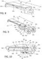
- FIG. 8 shows an enlarged perspective view of a secondary armrest front link 50 that can be configured to attach to the secondary armrest intermediate link 40 shown at least in FIG. 7 and described herein, according to present examples.
- secondary armrest front link 50 comprises a secondary armrest front link first surface (oriented in FIG. 8 as an "upper” surface") 52a and a secondary armrest front link second surface (oriented in FIG. 8 as an "lower” surface") 52b.
- Secondary armrest front link 50 further comprises a secondary armrest front link proximal end 52c that further comprises a secondary armrest intermediate link proximal end flange 54a that comprises a secondary armrest intermediate link proximal end flange through opening 54b.
- Secondary armrest intermediate front link 50 further comprises a secondary armrest front link distal end 52d.
- secondary armrest front link 50 further comprises a secondary armrest front link cushion first section 58 positioned adjacent to, and otherwise attached to the secondary armrest front link first surface 52a.
- the secondary armrest front link proximal end flange 54a has a selected width (e.g., a selected flange thickness, etc.) and is otherwise dimensioned to be accepted between the secondary armrest intermediate link distal end flanges 44a. That is, according to present examples, the secondary armrest intermediate link distal end flanges 44a are spaced apart to receive therebetween the secondary armrest front link proximal end flange 54a.
- the number of flanges and orientation of the flanges at the secondary armrest intermediate link distal end 44 and the secondary armrest front link proximal end 52c can vary, so long as the two link types are configured to movably and pivotably interconnect and articulate with one another such that the secondary armrest front link 50 achieves and retains a range of pivoting and articulating motion about a pin or other retainer interconnecting the secondary armrest front link 50 and the secondary armrest intermediate link 40 (e.g., the secondary armrest intermediate link distal end pin 44c, as shown in FIG. 7 ) to enable and allow the secondary armrest front link 50 to movably swivel, rotate, pivot, articulate, etc. horizontally or laterally with respect to the secondary armrest intermediate link 40.
- the two link types are configured to movably and pivotably interconnect and articulate with one another such that the secondary armrest front link 50 achieves and retains a range of pivoting and articulating motion about a pin or other retainer interconnecting the secondary armrest front link 50
- secondary armrest assembly 23 comprises a usable length L2 extending at least from the secondary armrest front link proximal end 52c to the secondary armrest front link distal end 52d.
- secondary armrest front link 50 comprises an average width W2, with the average width W2 that can be less than or equal to W1 of the primary armrest 20 (not shown in FIGs. 8 or 9 ).
- the secondary armrest front link 50, and the secondary armrest intermediate link 40 together and in movably pivotably joined combination can together form the secondary armrest assembly 23.
- the armrest assembly can be integrated into a structural component of a seat assembly, and the secondary armrest assembly 23 can movably and pivotably attach to the armrest assembly end link 24.
- the secondary armrest assembly can itself further comprise the armrest assembly end link 24, such that the armrest assembly 18 can be a three main component structure; e.g., the secondary armrest front link 50 movably and pivotably joined at the secondary armrest front link proximal end flange 54a to the secondary intermediate link distal end flange(s) 44a of the secondary armrest intermediate link 40 that is also movably and pivotably joined by the secondary armrest intermediate link proximal end flange 42a to the armrest assembly end link distal end flanges 28a of the armrest assembly end link 24, with the end link 24 then connected to a structural seat component (e.g., a seat assembly frame, etc.).
- a structural seat component e.g., a seat assembly frame, etc.
- the secondary armrest intermediate link 40 is shown movably and pivotably engaged with the secondary armrest front link 50, and with the upper secondary armrest intermediate link distal flange 44a covered by, and otherwise in contact with and supporting a fixedly attached secondary armrest intermediate link cushion second section 48.
- the secondary armrest assembly 23 is configured dimensionally to "nest" beneath a primary armrest when the secondary armrest assembly is in a stowed configuration (where, e.g., the secondary armrest assembly is longitudinally (or substantially longitudinally) aligned with the primary armrest and nests beneath the primary armrest, etc.).
- FIG. 10 is an enlarged perspective side, and slightly, elevated view of the armrest assembly 18 comprising the primary armrest 20 with the secondary armrest assembly 23 nested beneath the primary armrest 20. More specifically, as shown in FIG.
- the primary armrest 20 comprises a primary armrest first surface (e.g., an "upper” or “top” surface) 20a and a primary armrest second surface (e.g., a “lower” or “bottom” surface) 20b.
- Primary armrest 20 further comprises a primary armrest proximal end 20c and a primary armrest distal end 20d, with the primary armrest distal end 20d shown extending beyond and otherwise “covering" the distal end of the secondary armrest assembly 23.
- FIG. 10 shows the armrest assembly 18 showing the secondary armrest intermediate link distal end pin 44c disposed through the two secondary armrest intermediate link distal end flanges 44a and the secondary armrest front link proximal end flange 54a.
- the secondary armrest intermediate link distal end pin 44c can be, for example, a threaded pin, or a bolt that can be retained in position by mating with a threaded fastener 44d, etc.
- FIG. 10 further shows the armrest assembly end link 24 movably and pivotably engaged with the secondary armrest intermediate link 40, with the armrest assembly end link distal end pin 28c disposed through the two armrest assembly end link distal end flanges 28a and the secondary armrest intermediate link proximal end flange 42a.
- the armrest assembly end link distal end pin 28c can be, for example, a threaded pin, or a bolt that can be retained in position by mating with a threaded fastener 28d, etc.
- FIG. 10 further shows the armrest assembly end link proximal end flanges 26a comprising an armrest assembly end link proximal end flange through opening 26b with an armrest assembly end link proximal end flange pin 26c in position.
- the width of the secondary armrest assembly can be selected and dimensioned to be less than or equivalent to the width of the primary armrest, such that the secondary armrest assembly can fully nest beneath and adjacent to the primary armrest when the secondary armrest assembly is in the stowed configuration. In this way, in the stowed configuration, the secondary armrest is essentially "hidden" from view, when the overall armrest assembly is viewed from above.
- a force can be applied to the secondary armrest assembly (e.g., a manually applied force or an automated force, with an automated force that can be generated by, for example, a mechanical or electrical drive assembly, a hydraulic drive assembly, a pneumatic drive assembly, etc.) to move the secondary armrest assembly from a stowed configuration to an outwardly deployed configuration that is outward, away from, and out from under, etc., the primary armrest (e.g., the dimensional footprint of the primary armrest, at least in terms of the width of the primary armrest).
- a force can be applied to the secondary armrest assembly (e.g., a manually applied force or an automated force, with an automated force that can be generated by, for example, a mechanical or electrical drive assembly, a hydraulic drive assembly, a pneumatic drive assembly, etc.) to move the secondary armrest assembly from a stowed configuration to an outwardly deployed configuration that is outward, away from, and out from under, etc., the primary armrest (e.g., the dimensional
- FIG. 11A is an enlarged perspective view, according to present examples, of the armrest assembly installed in position within a seat assembly that can be, for example, a passenger seat assembly, and that can be of the type shown at least in FIGs.2 , 3 , 4 , and 10 , with a modification.
- armrest assembly 18 comprises the primary armrest 20 having a primary armrest first surface 20a, primary armrest second surface 20b, primary armrest proximal end 20c and primary armrest distal end 20d.
- a primary armrest cushion layer 22 is positioned adjacent to and otherwise is configured to cover the primary armrest first surface 20a..
- Secondary armrest assembly 23 is shown in a deployed configuration with the secondary armrest assembly 23 movably and pivotably articulated from the stowed position (e.g., the stowed position being the position where the secondary armrest assembly is nested and otherwise rests in a stowed position immediately beneath the primary armrest second surface 20b) and moved into the deployed position that is laterally adjacent to, and out from under, the footprint of the primary armrest 20.
- the stowed position being the position where the secondary armrest assembly is nested and otherwise rests in a stowed position immediately beneath the primary armrest second surface 20b
- secondary armrest front link 50 comprises a secondary armrest front link proximal end 52c and a secondary armrest front link distal end 52d, with the secondary armrest front link 50 as shown in FIG. 11A covered by a secondary armrest front link cushion first section 58.
- the secondary armrest intermediate link 40 is shown movably and pivotably engaged with the secondary armrest front link 50, with the secondary armrest intermediate link 40 covered by and otherwise supporting an attached secondary armrest intermediate link cushion second section 48.
- An armrest assembly end link 24 is partially visible in FIG. 11A and is shown movably and pivotally engaged with secondary armrest intermediate link 40.
- FIG. 11A further shows comparative dimensions (e.g., "length” (L1) and “width” (W1)) of the primary armrest 20 in comparison with the width (W2) and length (L2) of the secondary armrest assembly 23 comprising the secondary armrest front link 50.
- the primary armrest 20 comprises a length, L1 that extends from the primary armrest proximal end 20c to the primary armrest distal end 20d.
- Secondary armrest assembly 23 comprises a length L2 extending from the secondary armrest front link proximal end 52c (or also from the secondary armrest assembly intermediate link 40) to the secondary armrest front link distal end 52d.
- length L2 can be less that length L1.
- primary armrest 20 comprises an average width W1 and secondary armrest front link comprises an average width W2, wherein average width W2 can be less than or equal to W1.
- the height of the secondary armrest assembly in an initial deployed configuration approximates the height of the secondary armrest assembly in the stowed configuration, with the height of the secondary armrest assembly 23, as shown in FIG. 11A being less than (being lower than) the height of the primary armrest 20.
- the length of the secondary armrest assembly in the stowed and deployed configuration is less than the length of the primary armrest.
- the overall length of the secondary armrest assembly 23 can be altered, tailored, or otherwise adjusted from an initial length in the initial deployed configuration (with the initial length of the secondary armrest assembly in the deployed configuration approximating the length of the secondary armrest assembly in the stowed and fully retracted (or substantially fully retracted) configuration) to an increased second length or lengths in a fully deployed configuration.
- FIG. 11B shows the armrest assembly 18 similar to that shown in FIG.
- the secondary armrest assembly 23 is shown in an extended (e.g., an extended deployed) configuration such that the secondary armrest front link 50a can be extended, providing the secondary armrest assembly 23 with a significantly enhanced flexibility to convert the overall length of the secondary armrest assembly 23 to a plurality of adjustable and selected secondary armrest assembly lengths; with such plurality of selected secondary armrest assembly lengths configured to be equivalent to or greater than the length of the primary armrest 20.
- secondary armrest assembly 23 has a longer length (L3) that that length L2 shown in FIG. 11A.
- FIG. 11B shows the secondary front link 50a comprising a secondary armrest front link proximal end 52c and a secondary armrest front link distal end 52d.
- the secondary armrest front link distal end 52d can be extended longitudinally such that the secondary armrest front link 50a is configured to form a secondary armrest assembly 23 that is now longer (having a new secondary armrest length, L3) than the primary armrest 20 (e.g., the secondary armrest assembly now is configured to have a length L3 that is greater than the length L1 of the primary armrest 20).
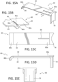
- the length L3 of the secondary armrest assembly can be attained by adjustably increasing the length of the secondary armrest front link 50a from an initial stowed length L2 by withdrawing or extracting or extending a secondary armrest front link length extender 52e (e.g. a front link extender that is contained within the secondary armrest front link 50a as a movable and extending part of the secondary armrest front link 50a).
- the secondary armrest front link length extender 52e can be an extendable member that extends along the longitudinal axis of the secondary armrest assembly 23.
- secondary armrest front link 50a can be configured to comprise a front link internal sleeve (not shown) comprising a front link recess bounded by the walls of the recess, with the recess dimensioned to accommodate the retracted storage of the secondary armrest front link length extender 52e in a stowed configuration, and otherwise facilitate the release of the extendable front link extender from a retracted configuration within a longitudinal front link recess, for example.
- the secondary armrest front link 50a can be configured to comprise a front link component that separates longitudinally for the purpose of extending the overall length of the secondary armrest front link 50a, and as shown in the FIGs. herein to both accommodate the retracted storage of the secondary armrest front link length extender 52e in a stowed configuration, and otherwise facilitate the release and extension of the extendable front link extender from a retracted configuration.
- the secondary armrest front link can further comprise a positional locking mechanism that can be in communication with actuators and otherwise be configured to communicate with the secondary armrest front link extender to effect an increase in the effective secondary armrest front link length representing a series of a fixed number of extending length "stops", or than can effect an increase in the effective secondary armrest front link length representing a theoretically infinite number of extending lengths through, for example, a tightening and loosening mechanism configured to allow the extender to achieve a multitude of varied extender lengths.
- the extender can be in communication with manually controlled and actuated as well as automated mechanical mechanisms that can, in turn be in communication with a controller that is further in communication with hardware and software responsible for sending signals to actuators and/or motors to electrically, hydraulically, pneumatically, etc. direct a force to the extender to both extend and retract and otherwise adjust the length of the extender that, in turn regulates the overall length of the secondary armrest front link length, further regulating the overall length of the secondary armrest assembly, at least distally, and in relation to the primary armrest of the armrest assembly.
- FIGs 14A, 14B, 14C , 14D, 15A, 15B , 16A, 16B, and 16C are shown herein in FIGs 14A, 14B, 14C , 14D, 15A, 15B , 16A, 16B, and 16C , and further described herein.
- FIG. 11B further shows comparative dimensions (e.g., "length (L1) and “width” (W1) of the primary armrest 20 in comparison with the width (W2) of the secondary armrest assembly 23 comprising the secondary armrest front link 50a, and the lengths of the secondary armrest front link both in retracted lengthwise, or stowed, configuration (L2) and the extended lengthwise, or deployed, configuration (L3).
- comparative dimensions e.g., "length (L1) and “width” (W1) of the primary armrest 20 in comparison with the width (W2) of the secondary armrest assembly 23 comprising the secondary armrest front link 50a, and the lengths of the secondary armrest front link both in retracted lengthwise, or stowed, configuration (L2) and the extended lengthwise, or deployed, configuration (L3).
- the secondary armrest assembly being configured to movably adjust the height of the secondary armrest assembly from an initial "height" relative to the primary armrest in the secondary armrest stowed configuration to a second "height" or “heights” in a secondary armrest assembly deployed state, such that the secondary armrest assembly can be movably adjusted vertically to a selected and adjustable height that is less than, equivalent to, or greater than the height of the primary armrest, and to a height that is different than the height of the secondary armrest assembly in the stowed state (e.g., beneath the primary armrest).
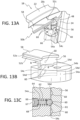
- the secondary armrest front link proximal flange can be modified to comprise a secondary armrest front link proximal end flange recess 54c that can be in form of a vertical recess bounded by vertical recess walls in the secondary armrest front link proximal end flange 54a.
- Such secondary armrest front link proximal end flange recess 54c in the secondary armrest front link proximal end flange 54a can be machined (e.g., drilling, etc., or can be molded, etc.) into a secondary armrest front link proximal end flange 54a.
- the secondary armrest front link proximal end flange recess 54c can be configured and otherwise dimensioned to receive a secondary armrest front link vertical extender 56.
- FIG. 12A is an enlarged perspective view of armrest assembly 18 in position in a seat assembly and positioned between adjoining seats in a seat assembly that can be, for example, a passenger seat assembly (that can be, for example, a passenger seat assembly in, for example, a passenger vehicle such as, for example, a passenger aircraft), and that can be of the type shown at least in FIGs.2 , 3 , 4 , 10 , 11A, and 11B .
- the armrest assembly shown in FIG. 12A is similar in many respects to the armrest assembly 18 shown in FIG. 11A , and similarly numbered features exist in FIGs. 12A and 11A .
- secondary armrest assembly 23 comprises a secondary armrest front link 50b that is dimensioned and otherwise configured to be received by a secondary armrest front link proximal end flange recess 54c in the secondary armrest front link proximal end flange 54a, with the secondary armrest front link proximal end flange recess 54c formed and defined by surrounding secondary armrest front link proximal flange recess walls (not visible in FIGs. 12A and 12B ) that descend into the secondary armrest front link proximal end flange 54a (e.g., descend into and within the body of the secondary armrest front link proximal end flange 54a).
- FIG. 12A secondary armrest front link 50b that is dimensioned and otherwise configured to be received by a secondary armrest front link proximal end flange recess 54c in the secondary armrest front link proximal end flange 54a, with the secondary armrest front link proximal end flange recess 54c formed and
- the secondary armrest front link 50b can be raised to height represented by "H2", that can be less than the overall length of the secondary armrest front link vertical extender 56.
- the distance or “height” that the vertical extender 56 is raised from the secondary armrest front link proximal end flange recess 54c can be a height required to move the front link 50b from an initial or secondary armrest front link "first" height in a stowed configuration that is lower than the height of the primary armrest 20 (e.g., a first "height” that allows the secondary armrest assembly to nest beneath the primary armrest - see, e.g., height "H1" of the secondary armrest shown in FIG.
- the secondary armrest front link can be adjusted, in terms of height, to a secondary armrest front link second height H2 (that is a distance value that less than, equal to, or greater than the height of the primary armrest) as selected, for example, by a seated passenger, and with H2 being a distance value, or "height" that is greater than H1.
- FIG. 12B is an enlarged perspective view of armrest assembly 18 in position in a seat assembly, and positioned between adjoining seats in a seat assembly that can be, for example, a passenger seat assembly, and that can be of the type shown at least in FIGs.2 , 3 , 4 , 10 , 11A, 11B , and 12A .
- the armrest assembly shown in FIG. 12B is similar in many respects to the armrest assembly 18 shown in FIG. 12A , and similarly numbered features exist in FIGs. 12A and 12BA.
- the secondary armrest assembly 23 in the deployed position can be variably adjusted vertically and otherwise configured to raise from, and retract (e.g., lower, etc.) back into the secondary armrest front link proximal end flange recess 54c such that the secondary armrest front link 50c is configured to be variably positioned to a selected height H2 relative to the height of the primary armrest 20.
- secondary armrest assembly 23 comprises a secondary armrest front link vertical extender 56 that is dimensioned and otherwise configured to be received by a secondary armrest front link proximal end flange recess 54c in the secondary armrest front link proximal end flange 54a, with the secondary armrest front link proximal end flange recess 54c formed and defined by surrounding secondary armrest front link proximal end flange recess walls 54d (not visible in FIGs. 12A and 12B , but shown, for example in FIG. 13B ) that descend into the secondary armrest front link proximal end flange recess 54c (e.g., descend into and within the body of the secondary armrest front link proximal end flange 54a).
- the secondary armrest assembly 23 is shown in an extended configuration such that the secondary armrest front link 50c also can be extended longitudinally outward to an extended length in and along the longitudinal axis of the secondary armrest front link 50c, and the secondary armrest assembly can also be extended vertically to variably adjust the secondary armrest front link 50c to a selected height H2 relative to the primary armrest. According to examples as shown in FIG. 12B and similar to the secondary armrest front link 50a shown in FIG. 11B , the secondary armrest assembly 23 is shown in an extended configuration such that the secondary armrest front link 50c also can be extended longitudinally outward to an extended length in and along the longitudinal axis of the secondary armrest front link 50c, and the secondary armrest assembly can also be extended vertically to variably adjust the secondary armrest front link 50c to a selected height H2 relative to the primary armrest. According to examples as shown in FIG.
- the secondary armrest front link 50c possesses attributes resulting in a secondary armrest assembly and an overall armrest assembly positional flexibility with respect to significantly enhanced flexibility to convert the overall length of the secondary armrest assembly to a plurality of selected secondary armrest assembly lengths L3 (with such plurality of selected secondary armrest assembly lengths L3 configured to be equivalent to or greater than the length of the primary armrest L1 and greater than the length of the secondary armrest in the stowed configuration, L2), as well as the aforementioned presently disclosed advantages with respect to the ability to attain variably adjustable secondary armrest front link heights, H2 (e.g., relative to the primary armrest height, etc.).
- secondary armrest assembly 23 has a longer length "L3" that that shown in FIG. 12A (e.g., as compared to length, "L2").
- FIG. 12B shows the secondary front link 50c comprising a secondary armrest front link proximal end 52c and a secondary armrest front link distal end 52d. As shown in FIG. 12A
- the secondary armrest front link distal end 52d can be extended outwardly along the longitudinal axis of the front link such that the secondary armrest front link 50c is configured to form a secondary armrest assembly 23 that is now in an extended configuration, and is now longer (e.g., now having a length, "L3") than the length "L1" of the primary armrest 20 (e.g., the secondary armrest assembly now is configured to have a length "L3" that is greater than both the length "L1" of the primary armrest, and the length "L2" of the secondary armrest front link when such front link is not in a non-extended configuration - e.g., when the secondary armrest is in a retracted or stowed configuration beneath the primary armrest, etc.).
- the length of the secondary armrest assembly 23 can be adjustably increased from an initial stowed length by withdrawing or extracting or extending a secondary armrest front link length extender 52e from the secondary armrest front link 50c.
- the secondary armrest assembly 23 being configured to also movably adjust the height of the secondary armrest assembly 23 in the deployed state such that the secondary armrest assembly 23 can be movably and variably adjusted vertically to a height H2 that is less than, equivalent to, or greater than the height of the primary armrest, and to a height that is different (e.g., greater than) than the height H1 secondary armrest assembly in the stowed state beneath the primary armrest.
- the secondary armrest intermediate link can further comprise a positional locking mechanism that can be in communication with actuators and otherwise be configured to communicate with the secondary armrest front link vertical extender to effect an increase in the effective secondary armrest front link height representing a series of a fixed number of extending height "stops", or than can effect an increase in the effective secondary armrest front link height representing a large number of varying extending heights through, for example, a tightening and loosening mechanism configured to allow the extender to achieve a multitude of varied extender lengths.
- the vertical extender of the secondary arm rest front link proximal end in combination with mechanisms in the secondary armrest front link proximal flange can be, for example, in communication with manually controlled and actuated mechanisms, as well as in communication with automated mechanical mechanisms that can, in turn, be in communication with a controller that is further in communication with hardware and software responsible for sending signals to actuators and/or motors to electrically, hydraulically, pneumatically, etc. direct a force to the front link vertical extender to both extend and retract and otherwise adjust the height of the front link vertical extender that, in turn, can regulate the overall height of the secondary armrest front link height, further regulating the overall height of the secondary armrest assembly, at least vertically, and in relation to the primary armrest of the armrest assembly.
- FIG. 13A is an enlarged partial view of the secondary armrest front link 50b as shown, for example, in FIG. 12A , and showing in greater detail the secondary armrest front link proximal end 52c comprising a secondary armrest front link vertical extender 56 engaged within a secondary armrest front link proximal end flange recess 54c as shown located at and within secondary armrest front link proximal end flange 54a.
- FIG. 13A further shows the location of indexing depressions 60 located in a vertical orientation along the reverse (internal) side segment of the length of secondary armrest front link vertical extender 56.
- FIG. 13C further illustrates the internal location of the indexing depressions 60.
- the indexing depressions 60 may be through openings (e.g., "holes") that can be, for example, indexing through holes extending through the thickness of the vertical extender 56.
- FIG. 13B is an enlarged view of the proximal end of the secondary armrest front link 50b that further illustrates the secondary armrest front link proximal end flange recess 54c that is dimensioned and that is otherwise configured to receive the secondary armrest front link vertical extender 56.
- the secondary armrest front link 50b comprises multiple components assembled to form the front link such that, for example, the secondary armrest front link proximal end flange 54a can be a component of the front link assembly that is in a movable configuration with the remainder of the secondary armrest front link features that can include, for example, the secondary armrest front link vertical extender 56 that can be integral with the secondary armrest front link second (e.g., lower) surface, for example.
- FIG. 13C is a cross-sectional view of the secondary armrest front link proximal end flange 54a shown in FIG. 13B taken along line B-B, with the internal locking mechanism 62 shown engaging the secondary armrest front link vertical extender 56 housed within the secondary armrest front link proximal end flange recess 54c located within the secondary armrest front link proximal end flange 54a.
- the indexing depressions 60 are configured to engage and otherwise come into direct physical and intimate contact with a component (e.g., a locking mechanism ball 61) of a locking mechanism 62 that translates an applied outward force to engage the indexing depression 60.
- a component e.g., a locking mechanism ball 61
- the locking mechanism 62 can be retained within a chamber 64 located within a section of the secondary armrest front link proximal flange 54a, and the locking mechanism 62 can be, for example, a ball-spring-grub screw type of mechanism comprising a spring component 68 in communication with a ball 61.
- FIG. 13C further shows a portion of the secondary armrest front link vertical extender 56 having indexing depressions 60 spaced along the vertical length, with the indexing depressions 60 configured to engage the ball 61 of the locking mechanism 62.
- Vertical extender 56 is shown in position within the secondary armrest front link proximal end flange recess 54c with secondary armrest front link proximal end flange recess wall 54d visible bounding the length of the secondary armrest front link proximal end flange recess 54c.
- FIGs. 14A, 14B, 14C , 15A, 15B, 15C, 15D, 15E , 16A, 16B, 16C show further features of secondary armrest front link length extenders and secondary armrest front link length extender assemblies that are contemplated as being incorporated into the secondary armrest assemblies presently contemplated according to present examples, and that can be of the type shown in FIGs. 11B and 12B , for example.
- a secondary armrest assembly 23 of the type shown, for example FIGs. 11B and 12B can include a secondary armrest front link 50a or 50c, respectively, that incorporates or is otherwise modified to incorporate an integrated front link length extender.
- FIGs 14A, 14B, 14C show an alternate example for forming a secondary armrest front link having a length extender.
- FIG. 14A shows a length extender 70 of the type that can be incorporated into a secondary armrest assembly 23 comprising a secondary armrest front link 50a, 50b, 50c (as shown in FIGs. 11B , 12A , 12B ).
- FIGs. 14A, 14B, and 14C further show views of a secondary armrest front link extender 70 (referred to equivalently herein as a "front link extender").
- FIG. 14A shows a perspective and slightly elevated view of view of a secondary armrest front link length extender 70 comprising a secondary armrest front link length extender proximal end 70a, a secondary armrest front link length extender distal end 70b, a secondary armrest front link length extender first side 72 (e.g. upper surface as shown), and a secondary armrest front link length extender second side 74 (e.g., lower surface as shown).
- secondary armrest front link length extender 70 further comprises an extender retaining projection 76 shown in FIG.
- the length extender retaining projection 76 can be configured and otherwise dimensioned along its length to incorporate flanges such that the extender retaining projection 76 is configured to engage, for example, a complimentary channel located in the secondary armrest front link such that the extender retaining projection 76 can slidably move a selected distance longitudinally along the length of the secondary armrest front link, and selectively extending the armrest length of the secondary armrest assembly.
- FIG. 14B is an overhead plan view of the secondary armrest front link extender 70 of the type shown in 14A, with FIG. 14C provided to show a side view of the secondary armrest front link length extender 70 of the type shown in FIGs. 14A and 14B .
- FIGs. 15A, 15B, 15C, and 15D show views of the secondary armrest front link 80 that is similar to the type shown as part 50c in FIG. 12B , with the secondary armrest front link 80 configured to incorporate the secondary armrest vertical extender 56 that is configured to extend vertically, for example, into the secondary armrest front link proximal end flange recess 54c, as shown at least in FIG. 12B .
- FIG. 15A shows an elevated perspective view of a secondary armrest front link similar to the secondary armrest front links shown in the FIGs., but without the secondary armrest front link proximal end flange 54a shown in FIGs 8, 9, 10 , 11A, 11B , 12A, 12B .
- secondary armrest front link 80 comprises a secondary armrest front link proximal end 80a, a secondary armrest front link distal end 80b, a secondary armrest front link first side 82 (e.g. upper surface as shown), and a secondary armrest front link second side 84 (e.g., lower surface as shown).
- secondary armrest front link 80 further comprises a secondary armrest front link retaining channel 86 that is shown in FIG. 15A as a linear depression or channel extending longitudinally a selected distance from the secondary armrest front link proximal end 80a toward the secondary armrest front link distal end 80b.
- the secondary armrest front link retaining channel 86 is dimensioned and otherwise configured to receive and engage (e.g., "mate" with, etc.) the extender retaining projection 76 of the length extender 70 shown in FIGs. 14A, 14B, 14C .
- the secondary armrest front link retaining channel 86 is configured to be a dimensionally complimentary channel located in the secondary armrest front link 80 such that the extender retaining projection 76 can mate with the retaining channel 86 such that the length extender 70 itself can mate with the front link 80, and such that the secondary armrest front link length extender 70 can slidably move a selected distance longitudinally along the length of the secondary armrest front link 80, to selectively extend the armrest length of the secondary armrest assembly to a selected distance that can be greater than the length of the secondary armrest front link 80 itself.
- FIG. 15B is a cutaway, cross-sectional and enlarged proximal end view of the secondary armrest front link 80 taken along line C-C as shown in FIG. 15A .
- secondary armrest front link proximal end 80a of secondary armrest front link 80 shows the retaining channel 86 present and contiguous with the secondary armrest front link first side 82, with retaining channel 86 comprising and defined by retaining channel walls 86a and retaining channel floor 86b.
- FIG. 15C is an overhead plan view of the secondary armrest front link 80 further showing the secondary armrest front link first side 82 and the retaining channel 86 positioned near the secondary armrest front link proximal end 80a that is in contact with secondary armrest front link vertical extender 56 that is dimensioned and otherwise configured to be received into a secondary armrest front link proximal end flange (not shown in FIGs. 15A-15D ), with the secondary armrest front link vertical extender 56 being integral with the front link 80.
- the vertical extender 56 can be a separate component that is fixedly attached to the front link 80, for example.
- FIG. 15D is a side view of the secondary armrest front link 80 shown in FIGs. 15A and 15C with the secondary armrest front link first and second surfaces 82, 84 (respectively) visible, along with the secondary armrest front link vertical extender 56.
- FIG. 15E is an end view of the secondary armrest front link proximal end 80a of the secondary armrest front link 80, further showing an end view of the secondary armrest front link vertical extender that can be integral with the front link.
- FIGs. 16A-16C show the secondary armrest front link as an assembly comprising the secondary armrest front link length extender 70 in combination with the secondary armrest front link 80 to form a completed front link assembly with the functioning length extender that can selectively and on demand increase the length of the secondary armrest front link, as well as extend the length of the overall secondary armrest assembly 23 shown in the FIGs. at least in FIG 10 , when the secondary armrest assembly 23 is moved from a nested secondary armrest assembly stowed position beneath the primary armrest 20 of armrest assembly 18 to a secondary armrest assembly deployed position that is positioned adjacent (or substantially adjacent) to the primary armrest 20 (as shown in FIGs. 11A, 11B , 12A, 12B , for example).
- secondary armrest front link length extender 70 can be brought into engageable contact with secondary armrest front link 80 such that the secondary armrest front link length extender second side 74 is brought into contact with secondary armrest front link first side 82 and with extender retaining projection 76 engaged with and configured to mate with and within secondary armrest front link retaining channel 86.
- FIG. 16B shows the assembled secondary armrest front link 80 now comprising the movably, and slidably attached secondary armrest front link length extender 70.
- FIG. 16C is a cutaway cross-sectional end view of the secondary armrest front link taken along line D-D.
- secondary armrest front link 80 with secondary armrest front link length extender 70 is in slidable and movable cooperative configuration such that the secondary armrest front link length extender second side 74 is in contact with secondary armrest front link first side 82 and with secondary armrest front link length extender retaining projection 76 configured to mate with and within the secondary armrest front link retaining channel 86.
- FIG. 16C further shows secondary armrest front link length extender retaining channel 86 comprising and otherwise defined by opposing secondary armrest front link retaining channel walls 86a and the secondary armrest front link retaining channel floor 86b.
- the secondary armrest front link assemblies shown in FIGs 14A-14C , 15A-15E , and 16A-16C are also directed to examples for constructing a secondary armrest assembly front link fitted with and otherwise comprising the secondary armrest front link length extender alone (not shown in the listed FIGs. in this paragraph), or for constructing the secondary armrest front link that is fitted with and otherwise comprises both the length extender and the secondary armrest front link vertical extender, as shown in the FIGs.
- FIGs. 17, 18 , 19 and 20 are flowcharts outlining methods according to further present examples employing the apparatuses, systems, assemblies, sub-assemblies disclosed and described at least in FIGs. 1-10 , 11A , 11B , 12A , 12B , 13A-13C , 14A-14C , 15A-15E , and 16A-16C .
- FIG. 1-10 11A , 11B , 12A , 12B , 13A-13C , 14A-14C , 15A-15E , and 16A-16C .
- FIG. 17 is a flowchart outlining a method 1300 for installing an armrest assembly into a seat assembly, according to present examples, with the method 1300 comprising providing 1302 a seat assembly comprising a seat assembly frame, with the seat assembly frame configured to support a plurality of seats, and attaching 1304 an armrest assembly to the seat assembly frame, with the armrest assembly comprising a secondary armrest front link, with the secondary armrest front link comprising a secondary armrest front link first surface (e.g., secondary armrest front link upper surface) and a secondary armrest front link second surface (e.g., secondary armrest front link lower surface), with the secondary armrest front link including a secondary armrest front link proximal end and a secondary armrest front link distal end, and with the secondary armrest front link proximal end comprising a secondary armrest front link proximal end flange, and with the secondary armrest front link proximal end flange comprising a secondary armrest front link proximal end flange through opening
- the secondary armrest assembly further includes a secondary armrest intermediate link, with the secondary armrest intermediate link including a secondary armrest intermediate link proximal end and a secondary armrest intermediate link distal end, with the secondary armrest intermediate link distal end including an secondary armrest intermediate link distal end flange configured to movably engage the secondary armrest front link proximal end flange, wherein the secondary armrest assembly is attached to the seat frame via an armrest assembly end link, with the armrest assembly end link comprising an armrest assembly end link proximal end and an armrest assembly end link distal end, with the armrest assembly end link distal end configured to movably engage the secondary armrest intermediate link proximal end flange, and with the armrest assembly end link proximal end configured to engage a seat assembly component that can be, for example, a seat frame.
- a seat assembly component that can be, for example, a seat frame.
- FIG. 18 is a flowchart illustrating a presently disclosed method 1400 that further comprises attaching 1402 a primary armrest assembly to the armrest assembly vis the armrest assembly end link, with the primary armrest assembly comprising a primary armrest assembly first surface (e.g., a primary armrest assembly upper surface) and a primary armrest assembly second surface (e.g., a primary armrest assembly lower surface), with the primary armrest assembly comprising a primary armrest proximal end and a primary armrest distal end, and with the primary armrest distal end configured to engage the armrest assembly end link.
- a primary armrest assembly first surface e.g., a primary armrest assembly upper surface
- a primary armrest assembly second surface e.g., a primary armrest assembly lower surface
- FIG. 19 is a flowchart illustrating a presently disclosed method 1500 further comprising nesting 1502 the secondary armrest assembly beneath the primary armrest assembly in a secondary armrest assembly stowed configuration.
- FIG. 20 is a flowchart outlining a presently disclosed method 1600 for installing a seat assembly into a passenger aircraft, with the method comprising installing 1602 a seat assembly into a passenger vehicle, with the seat assembly comprising an armrest assembly, and with the armrest assembly comprising a primary armrest assembly.
- the primary armrest assembly includes a primary armrest assembly first (upper) surface and a primary armrest second (lower) surface, with the primary armrest comprising a primary armrest proximal end and a primary armrest distal end.
- the armrest assembly further comprises a secondary armrest assembly, with the secondary armrest assembly comprising a secondary armrest front link, with the secondary armrest front link comprising a secondary armrest front link first (upper) surface and a secondary armrest front link second (lower) surface.
- the secondary armrest front link comprises a secondary armrest front link proximal end and a secondary armrest front link distal end, with the secondary armrest front link proximal end comprising a secondary armrest front link proximal end flange, with the secondary armrest front link proximal end flange comprising a secondary armrest front link proximal end flange through opening, and with the secondary armrest assembly further comprising an intermediate link.
- the secondary armrest intermediate link comprises a secondary armrest intermediate link proximal end and a secondary armrest intermediate link distal end, with the secondary armrest intermediate link distal end comprising a secondary intermediate link distal end flange configured to movably engage the secondary armrest front link proximal end flange.
- the secondary armrest assembly further comprises an armrest assembly end link, with the armrest assembly end link comprising an armrest assembly end link proximal end and an armrest assembly end link distal end, with the armrest assembly end link distal end configured to movably engage the secondary armrest intermediate link proximal end flange, and with the armrest assembly end link proximal end configured to engage a seat frame.
Landscapes
- Engineering & Computer Science (AREA)
- Aviation & Aerospace Engineering (AREA)
- Transportation (AREA)
- Mechanical Engineering (AREA)
- Seats For Vehicles (AREA)
Abstract
Description
- The present disclosure relates to the field of armrests, and armrest assemblies used for manufacturing seat assemblies. More specifically, the present disclosure relates to the field of armrests, and armrest assemblies used for manufacturing seat assemblies for vehicles including aircraft.
- Seating designed to accommodate more than one person often includes a plurality of individual and separated, as well as adjoined seats, located next to one another. Such seating designed to accommodate a plurality of people often position armrests for convenience that can act as separators delineating the area of individual seats. Where two seats adjoin one another, a single adjoining armrest often exists to service the occupants of adjoining seats. When adjoining seats are concurrently occupied by, for example, passengers, the armrest located between adjoining passengers must be shared if the armrest is to be used by both passengers. Such a shared armrest called upon to concurrently service adjoining passengers has been found to inadequately serve the needs of adjoining passengers.
- Unless explicitly identified as such, no statement herein is admitted as prior art merely by its inclusion in the Technological Field and/or Background section.
- Present examples are directed to an armrest assembly, with the armrest assembly including a primary armrest assembly. The primary armrest assembly includes a primary armrest assembly first surface (e.g., an upper surface) and a primary armrest assembly secondary (lower) surface (e.g., a lower surface), with the primary armrest assembly comprising a primary armrest proximal end and a primary armrest distal end, with the primary armrest proximal end in communication with a seat assembly. The armrest assembly further includes a secondary armrest assembly, with the secondary armrest assembly including a secondary armrest front link. The secondary armrest front link includes a secondary armrest front link first surface (e.g., an upper surface) and a secondary armrest front link second surface (e.g., a lower surface), with the secondary armrest front link further including a secondary armrest front link proximal end and a secondary armrest front link distal end. The secondary armrest front link proximal end includes a secondary armrest front link proximal end flange, and the secondary armrest front link proximal end flange includes a secondary armrest front link proximal end flange through opening. The secondary armrest assembly further includes a secondary armrest intermediate link, with the secondary armrest intermediate link including a secondary armrest intermediate link proximal end and a secondary armrest intermediate link distal end, and with the secondary armrest intermediate link distal end including a secondary armrest intermediate link distal end flange configured to movably and pivotably engage the secondary armrest front link proximal end flange.
- Optionally, the armrest assembly further includes an armrest assembly end link, with the armrest assembly end link including an armrest assembly end link proximal end and an armrest assembly end link distal end, and with the armrest assembly end link distal end configured to movably and pivotably engage the secondary armrest intermediate link proximal end flange, and with the armrest assembly end link proximal end configured to engage or otherwise be in communication with at least one of a seat frame, a seat assembly component, and a seat assembly.
- Optionally, the secondary armrest assembly is configured to move from a secondary armrest assembly stowed position located immediately beneath the primary armrest assembly and within a dimensional footprint of the primary armrest assembly, to a secondary armrest assembly deployed position located laterally adjacent to the primary armrest assembly (e.g.. the secondary armrest assembly in the deployed position is moved "out from under" the primary armrest assembly, and outside of or beyond the dimensional footprint of the primary armrest assembly such that the secondary armrest assembly is exposed.
- Optionally, the primary armrest assembly has a first average width (W1) along a longitudinal axis of the primary armrest assembly, and the secondary armrest front link has a second average width (W2) along a longitudinal axis of the secondary armrest assembly, with the first average width (W1) greater than or equal to the second average width (W2).
- Optionally, the secondary armrest assembly in the stowed position is configured to movably nest beneath and immediately adjacent to the primary armrest assembly.
- Optionally, the secondary armrest assembly further includes a secondary armrest front link length extender, with the secondary armrest front link length extender configured to extend outwardly to a selected extended distance from the secondary armrest front link distal end.
- Optionally, the secondary armrest front link length extender can be an extendable nested member that can extend from and retract to a secondary armrest front link length extender first position in the secondary armrest assembly to a secondary armrest front link length extender second position in the secondary armrest assembly.
- Optionally, the secondary armrest front link first surface comprises a secondary armrest front link first surface area, and wherein the entirety of the secondary armrest front link first surface area is exposed in the secondary armrest assembly deployed position.
- Optionally, the secondary armrest front link first surface includes a secondary armrest cushion layer first section, with the intermediate link including a secondary armrest cushion layer second section, and with the primary armrest assembly first surface including a primary armrest assembly cushion layer.
- Optionally, in the secondary armrest assembly deployed position, the secondary armrest cushion layer first section is positioned at a secondary armrest cushion layer first section relative height, with the secondary armrest cushion layer first section relative height varying from a primary armrest assembly cushion layer relative height.
- Optionally, the intermediate link proximal end is configured to movably engage with the end link distal end, and with the intermediate link configured to movably pivot horizontally about the end link distal end.
- Optionally, the secondary armrest front link proximal end is configured to movably and pivotably engage with the intermediate link distal end, with the secondary armrest front link further configured to movably pivot horizontally about the intermediate link distal end.
- A further example is directed to a seat assembly, with the seat assembly including an armrest assembly, with the armrest assembly including a primary armrest assembly including a primary armrest assembly first surface (e.g., an upper surface) and a primary armrest assembly second (lower) surface (e.g., a lower surface), with the primary armrest assembly further including a primary armrest proximal end and a primary armrest distal end. The armrest assembly further includes a secondary armrest assembly, with the secondary armrest assembly including a secondary armrest front link. The secondary armrest front link includes a secondary armrest front link first surface (e.g., an upper surface) and a secondary armrest front link second surface (e.g., a lower surface), with the secondary armrest front link including a secondary armrest front link proximal end and a secondary armrest front link distal end. The secondary armrest front link proximal end includes a secondary armrest front link proximal end flange, and the secondary armrest front link proximal end flange includes a secondary armrest front link proximal end flange through opening. The secondary armrest assembly further includes a secondary armrest intermediate link, with the secondary armrest intermediate link including a secondary armrest intermediate link proximal end and a secondary armrest intermediate link distal end, and with the secondary armrest intermediate link distal end including a secondary armrest intermediate link distal end flange configured to movably engage the secondary armrest front link proximal end flange. The armrest assembly further includes an armrest assembly end link, with the armrest assembly end link including an armrest assembly end link proximal end and an armrest assembly end link distal end, and with the armrest assembly end link distal end configured to movably engage the secondary armrest intermediate link proximal end flange, and with the armrest assembly end link proximal end configured to engage at least one of a seat frame, a seat frame component, and a seat assembly.
- Further examples are directed to a passenger vehicle including the seating assemblies disclosed herein.
- Further examples are directed to a passenger vehicle including the armrest assemblies disclosed herein.
- Optionally, the passenger vehicle including the presently disclosed armrest assemblies is selected from the group consisting of a crewed aircraft, an uncrewed aircraft, a crewed spacecraft, an uncrewed spacecraft, a crewed rotorcraft, an uncrewed rotorcraft, a crewed terrestrial vehicle, an uncrewed terrestrial vehicle; a crewed surface water borne vehicle, an uncrewed waterborne vehicle, a crewed sub-surface water borne vehicle, an uncrewed sub-surface water borne vehicle, and combinations thereof.
- Still further examples are directed to aircraft, that can include passenger aircraft comprising the presently disclosed armrest assemblies.
- Still further examples are directed to aircraft, that can include passenger aircraft comprising the presently disclosed seating assemblies
- According to further examples, a secondary armrest assembly is presently disclosed, with the secondary armrest assembly including a secondary armrest front link, and with the secondary armrest front link comprising a secondary armrest front link first surface (e.g., secondary armrest front link upper surface) and a secondary armrest front link second surface (e.g., secondary armrest front link lower surface), with the secondary armrest front link including a secondary armrest front link proximal end and a secondary armrest front link distal end, and with the secondary armrest front link proximal end comprising a secondary armrest front link proximal end flange, and with the secondary armrest front link proximal end flange comprising a secondary armrest front link proximal end flange through opening. The secondary armrest assembly further includes a secondary armrest intermediate link, with the secondary armrest intermediate link including a secondary armrest intermediate link proximal end and a secondary armrest intermediate link distal end, with the secondary armrest intermediate link distal end including a secondary armrest intermediate link distal end flange configured to movably and pivotably engage the secondary armrest front link proximal end flange. Optionally, the secondary armrest assembly is configured to move from a secondary armrest assembly stowed position to a secondary armrest assembly deployed position.
- Optionally, the secondary armrest assembly is in communication with an armrest assembly end link, with the armrest assembly end link including an armrest assembly end link proximal end and an armrest assembly end link distal end, with the armrest assembly end link distal end configured to movably and pivotably engage the secondary armrest intermediate link proximal end flange, and with the armrest assembly end link proximal end configured to engage at least one of a seat frame, a seat frame component, and a seat assembly.
- Optionally, the secondary armrest assembly in the stowed position is configured and dimensioned to movably and/or pivotably nest beneath a primary armrest assembly.
- Optionally, the secondary armrest assembly further includes a secondary armrest front link extender, with the secondary armrest front link extender configured to extend to a selected distance outwardly from the secondary armrest front link distal end in an extended configuration that is different from and great than secondary armrest front link extender initial position (e.g., a non-extended position) along the longitudinal axis of the secondary armrest assembly.
- Optionally, the secondary armrest front link is configured to extend vertically to a selected height in a secondary armrest front link vertically extended configuration, with the selected height in a secondary armrest front link vertically extended configuration different than a secondary armrest front link height in the secondary armrest assembly stowed configuration.
- Further examples are directed to a seat assembly comprising the secondary armrest assembly disclosed herein.
- Another example is directed to a passenger vehicle including the seat assembly comprising the secondary armrest assembly disclosed herein, with the passenger vehicle selected from the group consisting of a crewed aircraft, an uncrewed aircraft, a crewed spacecraft, an uncrewed spacecraft, a crewed rotorcraft, an uncrewed rotorcraft, a crewed terrestrial vehicle, an uncrewed terrestrial vehicle; a crewed surface water borne vehicle, an uncrewed waterborne vehicle, a crewed sub-surface water borne vehicle, an uncrewed sub-surface water borne vehicle, and combinations thereof.
- Another example is directed to an aircraft comprising the seat assembly comprising the secondary armrest assembly disclosed herein.
- According to further examples, a method for installing an armrest assembly into a seat assembly is disclosed, with the method comprising providing a seat assembly comprising a seat assembly frame, with the seat assembly frame configured to support a plurality of seats, and attaching an armrest assembly to the seat assembly frame, with the armrest assembly comprising a secondary armrest front link, with the secondary armrest front link comprising a secondary armrest front link first surface (e.g., secondary armrest front link upper surface) and a secondary armrest front link second surface (e.g., secondary armrest front link lower surface), with the secondary armrest front link including a secondary armrest front link proximal end and a secondary armrest front link distal end, and with the secondary armrest front link proximal end comprising a secondary armrest front link proximal end flange, and with the secondary armrest front link proximal end flange comprising a secondary armrest front link proximal end flange through opening. The secondary armrest assembly further includes a secondary armrest intermediate link, with the secondary armrest intermediate link including a secondary armrest intermediate link proximal end and a secondary armrest intermediate link distal end, with the secondary armrest intermediate link distal end including a secondary armrest intermediate link distal end flange configured to movably and pivotably engage the secondary armrest proximal end flange, wherein the secondary armrest assembly is attached to the seat frame via an armrest assembly end link, with the armrest assembly end link comprising an armrest assembly end link proximal end and an armrest assembly end link distal end, with the armrest assembly end link distal end configured to movably engage the armrest assembly intermediate link proximal end flange, and with the armrest assembly end link proximal end configured to engage at least one of a seat assembly frame, a seat frame component, and a seat assembly.
- Optionally, the method further comprises attaching a primary armrest assembly to the armrest assembly end link, with the primary armrest assembly comprising a primary armrest assembly first surface (e.g., a primary armrest assembly upper surface) and a primary armrest assembly second surface (e.g., a primary armrest assembly lower surface), with the primary armrest assembly comprising a primary armrest proximal end and a primary armrest distal end, with the primary armrest distal end, and with the primary armrest distal end configured to engage the armrest assembly end link.
- Optionally, the method further comprises nesting the secondary armrest assembly beneath the primary armrest assembly in a secondary armrest assembly stowed configuration.
- In yet another example, a method for installing a seat assembly into a passenger aircraft is disclosed, with the method comprising installing a seat assembly into a passenger vehicle, with the seat assembly comprising an armrest assembly, and with the armrest assembly comprising a primary armrest assembly. The primary armrest assembly includes a primary armrest assembly first (upper) surface and a primary armrest assembly second (lower) surface, with the primary armrest assembly comprising a primary armrest proximal end and a primary armrest distal end. The armrest assembly further comprises a secondary armrest assembly, with the secondary armrest assembly comprising a secondary armrest front link, with the secondary armrest front link comprising a secondary armrest front link first (upper) surface and a secondary armrest front link second (lower) surface. The secondary armrest front link comprises a secondary armrest front link proximal end and a secondary armrest front link distal end, with the secondary armrest front link proximal end comprising a secondary armrest front link proximal end flange, with the secondary armrest front link proximal end flange comprising a secondary armrest front link proximal end flange through opening, and with the secondary armrest assembly further comprising a secondary armrest intermediate link. The secondary armrest intermediate link comprises a secondary armrest intermediate link proximal end and a secondary armrest intermediate link distal end, with the secondary armrest intermediate link distal end comprising a secondary armrest intermediate link distal end flange configured to movably and pivotably engage the secondary armrest front link proximal end flange. The secondary armrest assembly further comprises an armrest assembly end link, with the armrest assembly end link comprising an armrest assembly end link proximal end and an armrest assembly end link distal end, with the armrest assembly end link distal end configured to movably engage the secondary armrest intermediate link proximal end flange, and with the armrest assembly end link proximal end configured to engage at least one of a seat assembly frame, a seat frame component, and a seat assembly seat frame.
- An example provides armrest assembly comprising: a primary armrest assembly. The primary armrest assembly comprises: a primary armrest first (upper) surface and a primary armrest second (lower) surface, the primary armrest comprising a primary armrest proximal end and a primary armrest distal end, the primary armrest proximal end in communication with a seat assembly. The armrest assembly further comprises a secondary armrest assembly comprising: a secondary armrest front link, the secondary armrest front link comprising a secondary armrest front link first (upper) surface, a secondary armrest front link second (lower) surface, a secondary armrest front link proximal end and a secondary armrest front link distal end. Either: the secondary armrest front link proximal end comprises a secondary armrest front link proximal end flange, the secondary armrest front link proximal end comprising a secondary front link proximal end flange; or the secondary armrest front link proximal end comprises a secondary armrest front link proximal end flange, the secondary armrest front link proximal end flange comprising a secondary front link proximal end flange through opening. The secondary armrest assembly further comprises a secondary armrest intermediate link, the secondary armrest intermediate link comprising a secondary armrest intermediate link proximal end comprising a secondary armrest intermediate proximal end flange, and a secondary armrest intermediate link distal end. The secondary armrest intermediate link distal end comprises at least one intermediate link distal end flange configured to movably and pivotably engage the secondary armrest front link proximal flange. The armrest assembly further comprises an armrest assembly end link comprising an armrest assembly end link proximal end comprising an armrest assembly end link proximal end flange, the armrest assembly end link further comprising an armrest assembly end link distal end comprising an armrest assembly end link distal end flange. The armrest assembly end link distal end is configured to movably and pivotable engage the intermediate link proximal end flange, the armrest assembly end link proximal end configured to engage at least one of a seat frame and the seat assembly.
- Optionally, the secondary armrest assembly is configured to move from a secondary armrest assembly stowed position immediately beneath the primary armrest assembly, and within a dimensional footprint of the primary armrest assembly, to a secondary armrest assembly deployed position laterally adjacent to the primary armrest assembly.
- Optionally, the secondary armrest assembly in the secondary armrest assembly stowed position is configured to movably nest beneath the primary armrest assembly.
- Optionally, the secondary armrest assembly further comprises a secondary armrest front link length extender, the secondary armrest front link length extender configured to extend outwardly to a selected extended distance from the secondary armrest front link distal end.
- Optionally, the primary armrest assembly has a first average width perpendicular to a primary armrest longitudinal axis, and the secondary armrest front link has a second average width perpendicular to a secondary armrest front link longitudinal axis, the first average width greater than or equal to the second average width.
- Optionally, the secondary armrest front link first surface comprises a secondary armrest front link first surface area, and wherein the entirety of the secondary armrest front link first surface area is exposed in the secondary armrest assembly deployed position.
- Optionally, the secondary armrest front link first surface comprises a secondary armrest cushion layer first section, the secondary armrest intermediate link comprises a secondary armrest cushion layer second section, and the primary armrest first surface comprises a primary armrest assembly cushion layer.
- Optionally, in the secondary armrest assembly deployed position, the secondary armrest front link is positioned at a secondary armrest front link average height, the secondary armrest front link average height varying from a primary armrest assembly average height.
- Optionally, the secondary armrest intermediate link proximal end flange is configured to movably engage with the armrest assembly end link distal end, the secondary armrest intermediate link configured to movably pivot about the armrest assembly end link distal end.
- Optionally, the secondary armrest front link proximal end flange is configured to movably engage with the secondary armrest intermediate link distal end, the secondary armrest front link proximal end further configured to movably pivot about the secondary armrest intermediate link distal end.
- Another example provides a seat assembly comprising any of the armrest assemblies described above. Another example provides a passenger vehicle comprising any of the armrest assemblies described above. Optionally, the passenger vehicle is selected from the group consisting of: a crewed aircraft, an uncrewed aircraft, a crewed spacecraft, an uncrewed spacecraft, a crewed rotorcraft, an uncrewed rotorcraft, a crewed terrestrial vehicle, an uncrewed terrestrial vehicle; a crewed surface water borne vehicle, an uncrewed waterborne vehicle, a crewed sub-surface water borne vehicle, an uncrewed sub-surface water borne vehicle, a satellite, and combinations thereof. Another example provides an aircraft comprising any of the armrest assemblies described above.
- Another example provides a secondary armrest assembly comprising: a secondary armrest front link, the secondary armrest front link comprising a secondary armrest front link first (upper) surface and a secondary armrest front link second (lower) surface, the secondary armrest front link comprising a secondary armrest front link proximal end and a secondary armrest front link distal end, the second armrest front link proximal end comprising a second armrest front link proximal end flange, the second armrest front link proximal end flange comprising a second armrest front link proximal end flange through opening. The secondary armrest assembly further comprises a secondary armrest intermediate link, the secondary armrest intermediate link comprising a secondary armrest intermediate link proximal end and a secondary armrest intermediate link distal end, the secondary armrest intermediate link distal end comprising a secondary armrest intermediate link distal end flange configured to receive and maintain a secondary armrest intermediate link distal end pin, and the secondary armrest intermediate link distal end flange configured to movably and pivotably engage the secondary armrest front link proximal end flange. The secondary armrest assembly is configured to move from a secondary armrest assembly stowed position beneath a primary armrest assembly to a secondary armrest assembly deployed position.
- Optionally, the secondary armrest assembly is in communication with an armrest assembly end link, the armrest assembly end link comprising an armrest assembly end link proximal end and an armrest assembly end link distal end, the armrest assembly end link distal end configured to movably and pivotably engage the secondary armrest intermediate link proximal end flange, the secondary armrest end link proximal end configured to engage at least one of a seat frame and a seat frame assembly.
- Optionally, the secondary armrest assembly in the secondary armrest assembly stowed position is configured and dimensioned to movably nest beneath the primary armrest assembly.
- Optionally, the secondary armrest assembly further comprises a secondary armrest front link extender, the secondary armrest front link extender configured to extend distally outward a selected distance from the secondary armrest front link distal end along a secondary armrest front link longitudinal axis.
- Optionally, the secondary armrest assembly front link first surface comprises a secondary armrest cushion first section, and the secondary armrest intermediate link comprises a secondary armrest cushion second section.
- Optionally, the secondary armrest intermediate link proximal end is configured to movably engage with the armrest assembly end link distal end, the secondary armrest intermediate link configured to movably pivot about the armrest assembly end link distal end.
- Optionally, the secondary armrest front link proximal end is configured to movably engage with the secondary armrest intermediate link distal end, the secondary armrest front link proximal end further configured to movably pivot about the secondary armrest intermediate link distal end.
- Optionally, the secondary armrest front link configured to extend vertically from the secondary armrest assembly to a selected height.
- Another example provides a seat assembly comprising any of the secondary armrest assemblies described above. Another example provides a passenger vehicle comprising any of the secondary armrest assemblies described above. Optionally, the passenger vehicle is selected from the group consisting of: a crewed aircraft, an uncrewed aircraft, a crewed spacecraft, an uncrewed spacecraft, a crewed rotorcraft, an uncrewed rotorcraft, a crewed terrestrial vehicle, an uncrewed terrestrial vehicle; a crewed surface water borne vehicle, an uncrewed waterborne vehicle, a crewed sub-surface water borne vehicle, an uncrewed sub-surface water borne vehicle, a satellite, and combinations thereof. Another example provides an aircraft comprising any of the secondary armrest assemblies described above.
- Another example provides a method for installing an armrest assembly into a seat assembly, the method comprising: providing a seat assembly, the seat assembly comprising a seat assembly frame. The method further comprises attaching a secondary armrest assembly to at least one of the seat assembly and the seat assembly frame, the secondary armrest assembly comprising: a secondary armrest front link, the secondary armrest front link comprising a secondary armrest front link first (upper) surface and a secondary armrest front link second (lower) surface, the secondary armrest front link further comprising a secondary armrest front link proximal end and a secondary armrest front link distal end, the second armrest front link proximal end comprising a second armrest front link proximal end flange, the second armrest front link proximal end flange comprising a second armrest front link proximal end flange through opening; and a secondary armrest intermediate link, the secondary armrest intermediate link comprising a secondary armrest intermediate link proximal end and a secondary armrest intermediate link distal end, the secondary armrest intermediate link distal end comprising a secondary armrest intermediate link distal end flange configured to movably engage the secondary armrest front link proximal end flange. The secondary armrest assembly is attached to the at least one of the seat assembly and the seat assembly frame via an armrest assembly end link, the armrest assembly end link comprising an armrest assembly end link proximal end and an armrest assembly end link distal end, the armrest assembly end link distal end configured to movably engage the secondary armrest intermediate link proximal end flange, the armrest assembly end link proximal end configured to engage the at least one of the seat assembly and the seat assembly frame.
- Optionally, the method further comprises: attaching a primary armrest assembly to the armrest assembly end link, the primary armrest assembly comprising a primary armrest assembly first (upper) surface and a primary armrest assembly second (lower) surface, the primary armrest assembly comprising a primary armrest proximal end and a primary armrest distal end, the primary armrest distal end configured to engage the armrest assembly end link.
- Optionally, the method further comprises: nesting the secondary armrest assembly beneath the primary armrest assembly in a secondary armrest assembly stowed configuration.
- Another example provides a method for installing a seat assembly into a passenger vehicle, the method comprising: installing a seat assembly into a passenger vehicle, the seat assembly comprising an armrest assembly. The armrest assembly comprises: a primary armrest assembly, the primary armrest assembly comprising a primary armrest assembly first (upper) surface and a primary armrest assembly second (lower) surface. The primary armrest assembly further comprises a primary armrest proximal end and a primary armrest distal end. The seat assembly further comprises a secondary armrest assembly, the secondary armrest assembly comprising a secondary armrest front link, the secondary armrest front link comprising a second armrest front link first (upper) surface and a secondary armrest front link second (lower) surface, the secondary armrest front link further comprising a secondary armrest front link proximal end and a secondary armrest front link distal end, the second armrest front link proximal end comprising a second armrest front link proximal end flange, the second armrest front link proximal end flange comprising a second armrest front link proximal end flange through opening. The second armrest assembly further comprises: a secondary armrest intermediate link, the secondary armrest intermediate link comprising a secondary armrest intermediate link proximal end and an intermediate link distal end, the intermediate link distal end comprising an intermediate link distal end flange configured to movably engage the secondary armrest front link proximal end flange. The armrest assembly further comprises an armrest assembly end link, the armrest assembly end link comprising an armrest assembly end link proximal end and an armrest assembly end link distal end, the armrest assembly end link distal end configured to movably engage the secondary armrest intermediate link proximal end flange, the armrest assembly end link proximal end configured to engage at least one of the seat assembly and a seat assembly frame.
- Optionally, the passenger vehicle is selected from the group consisting of: a crewed aircraft, an uncrewed aircraft, a crewed spacecraft, an uncrewed spacecraft, a crewed rotorcraft, an uncrewed rotorcraft, a crewed terrestrial vehicle, an uncrewed terrestrial vehicle; a crewed surface water borne vehicle, an uncrewed waterborne vehicle, a crewed sub-surface water borne vehicle, an uncrewed sub-surface water borne vehicle, a satellite, and combinations thereof. Optionally, the passenger vehicle is an aircraft.
- The features, functions and advantages that have been discussed can be achieved independently in various examples or may be combined in yet other examples, further details of which can be seen with reference to the following description and the drawings.
- Having thus described variations of the disclosure in general terms, reference will now be made to the accompanying drawings, which are not necessarily drawn to scale, and wherein:
-
FIG. 1 is an illustration of a vehicle in the form of an aircraft; -
FIG. 2 is a cross-sectional view of a vehicle in the form of an aircraft, as shown inFIG. 1 ; -
FIG. 3 is a representative view of a seat assembly comprising a plurality of armrest assemblies; -
FIG. 4 is a representative view of a seat assembly comprising a plurality of armrest assemblies; -
FIG. 5 is a side view of an armrest assembly; -
FIG. 6 is an overhead plan view of an armrest assembly; -
FIG. 7 is a perspective view of a secondary armrest assembly in a disassembled state; -
FIG. 8 is a perspective side view of a front link component of a secondary armrest assembly; -
FIG. 9 is a perspective side view of an intermediate link component of a secondary armrest assembly; -
FIG. 10 is a perspective side view of an end link component of a secondary armrest assembly; -
FIG. 11A is a perspective view of an armrest assembly with a secondary armrest in position in a deployed state; -
FIG. 11B is a perspective view of an armrest assembly with a secondary armrest in position in a deployed state -
FIG. 12A is a perspective view of an armrest assembly with a secondary armrest in position in a deployed state; -
FIG. 12B is a perspective view of an armrest assembly with a secondary armrest in position in a deployed state; -
FIG. 13A is an enlarged view of an armrest assembly with a secondary armrest in position in a deployed state; -
FIG. 13B is an enlarged view of the proximal end of the secondary armrest intermediate link; -
FIG. 13C is a cross-sectional view of the secondary armrest intermediate link distal end; -
FIG. 14A is a perspective view of the secondary armrest front link length extender; -
FIG. 14B is an overhead plan view of the secondary armrest front link length extender; -
FIG. 14C is a side view of the secondary armrest front link length extender; -
FIG. 15A is an exploded perspective view of the secondary armrest front link assembly; -
FIG. 15B is a perspective cutaway view of the secondary armrest front link assembly shown inFIG. 15A ; -
FIG. 15C is an overhead plan view of the secondary armrest front link assembly; -
FIG. 15D is a side view of the secondary armrest front link assembly shown inFIG. 15C -
FIG. 15E is a proximal end view of the secondary armrest front link assembly proximal end; -
FIG. 16A is an exploded view of segments of the secondary armrest front link assembly; -
FIG. 16B is a perspective view of the segments (as shown inFIG. 16A ) together arranged to form a secondary armrest front link assembly; -
FIG. 16C is a sectional view of the secondary armrest front link assembly as shown inFIG. 16B taken across line D-D; -
FIG. 17 is a flowchart illustrating a method; -
FIG. 18 is a flowchart illustrating a method; -
FIG. 19 is a flowchart illustrating a method; and -
FIG. 20 is a flowchart illustrating a method. - According to present examples, an armrest assembly is disclosed having a primary armrest and a secondary armrest assembly that can be stowed beneath the primary armrest in a nested configuration beneath the primary armrest. The secondary armrest can be manipulated from a stowed configuration beneath the primary armrest to a deployed configuration that exposes the secondary armrest and positions the secondary armrest to a deployed position that is laterally adjacent to the primary armrest. The height of the secondary armrest, when deployed, can be adjusted by vertically raising the secondary armrest to a height that is lower than, equivalent to, or higher than the height of the primary armrest that may be a fixed primary armrest height.
- As shown in the accompanying FIGs., the secondary armrest comprises a secondary armrest assembly that comprises a plurality of moving parts that together facilitated a manipulated and articulated movement of the secondary armrest from a secondary armrest stowed position beneath a primary armrest to a secondary armrest deployed position where the secondary armrest assembly is positioned adjacent to the primary armrest.
- The presently disclosed armrest assemblies can be installed into seat assemblies within a seat assembly frame that can support a plurality of adjacently positioned seats within the seat assembly frame. The seating assemblies disclosed herein can stand alone and be positioned in areas designed to seat occupants including, for example, waiting areas, theaters, lecture halls, etc. The seating assemblies disclosed herein can also be incorporated into larger structures including vehicles that can further include, for example, passenger vehicles such as, for example, cars, busses, trains, boats, aircraft, etc. Accordingly, the presently disclosed seating assemblies comprising the presently disclosed armrest assemblies can find utility installed into vehicles including passenger vehicles such as, for example, a crewed aircraft, an uncrewed aircraft, a crewed spacecraft, an uncrewed spacecraft, a crewed rotorcraft, an uncrewed rotorcraft, a crewed terrestrial vehicle, an uncrewed terrestrial vehicle; a crewed surface water borne vehicle, an uncrewed waterborne vehicle, a crewed sub-surface water borne vehicle, an uncrewed sub-surface water borne vehicle, and combinations thereof.
-
FIG. 1 is an illustration of a vehicle in the form of an aircraft, according to present examples. As shown inFIG. 1 ,aircraft 10 includesfuselage 12.FIG. 2 is a cross-sectional view ofaircraft 10 shown inFIG. 1 and taken across line "A-A", as also shown inFIG. 1 .FIG. 2 shows a view into anaircraft cabin 14 ofaircraft 10, with the aircraft bounded by the interior offuselage 12 and assemblies that may be attached to the interior offuselage 12.FIG. 2 further illustratesseat assemblies 16 positioned throughout the cabin in a selected seating orientation, with theseating assemblies 16 comprising seat assembly frames 17 (seat assembly frames 17 also shown inFIGs. 3 and 4 ) configured to secure the seating assembly to one or more fixtures located within theaircraft cabin 14 such as, for example, an aircraft cabin floor, structural assemblies in communication with an aircraft cabin floor, aircraft cabin monuments, etc.Seat assemblies 16 are further shown comprisingindividual seats seat assembly 16. Whenseats seats armrest assembly 18 positioned between adjoining seats (e.g., positioned betweenseats -
FIGs. 3 and 4 are slightly elevated and enlarged front views of aseat assembly 16 comprising adjoinedseats seat assembly 16 further comprisingseat assembly frame 17 that is configured to fixedly attachseat assembly 16 in a fixed position (within, for example, an aircraft cabin) to a structural component or structural assembly (not shown inFIGs. 3 or 4 ). -
FIG. 3 shows a passenger 15 (drawn as an outline) representing a passenger seated inseat 16b. As shown inFIG. 3 ,passenger 15 seated inseat 16b has an arm placed on anarmrest assembly 18.FIG. 4 showspassengers seats FIG. 4 ,passengers armrest assemblies 18 seated inseat 16b has an arm placed on aprimary armrest 20 ofarmrest assembly 18. -
FIG. 4 is a slightly elevated and enlarged front view of aseat assembly 16 comprising adjoinedseats seat assembly 16 further comprisingseat assembly frame 17 that is configured to fixedly attachseat assembly 16 in a fixed position (within, for example, an aircraft cabin) to a structural component or structural assembly (not shown inFIGs. 3 or 4). FIG. 3 further shows a passenger 15 (drawn as an outline) representing a passenger seated inseat 16b. As shown inFIG. 3 ,passenger 15 seated inseat 16b has an arm placed on aprimary armrest 20 of anarmrest assembly 18. - Although not explicitly shown or easily viewed in
FIGs. 3 or 4 ,armrest assemblies 18 that are positioned between adjacent and/or adjoining seats can be movably and pivotably attached (e.g., configured to facilitate a vertically pivoting motion about a fixed point that can be, for example, a pin), or are otherwise in movable and pivotable communication withseat assembly 16 and/orseat assembly frame 17, or another seat assembly component, etc., witharmrest assemblies 18 configured to move and pivot from a deployed horizontal (or substantially horizontal) position ready for use (e.g., by a seated passenger), to a retracted and stowed position that can be a vertical (or substantially vertical) stowed position between adjacent seats, and that can be coincident with a positioning of the armrest assembly between adjacent/adjoining seat backs of seats in a seat assembly of the type shown and described herein. As shown inFIG. 4 ,passengers passengers - Returning to
FIG. 3 ,armrest assembly 18 is shown in further detail withpassenger 15 having arms on aprimary armrest 20 ofarmrest assembly 18.FIG. 3 further showssecondary armrest assembly 23 deployed into a deployed position from a stowed position (e.g., a "nested" position) beneathprimary armrest 20 ofarmrest assembly 18. In the stowed or "nested" configuration, thesecondary armrest assembly 23 is in significant alignment with, and beneath, theprimary armrest 20 ofarmrest assembly 18. That is, whatever dimensional surface footprint the upper surface (e.g., the surface area, etc.) of the secondary armrest assembly has (particularly the secondary armrest front link discussed in more detail herein), according to present examples, such dimensional footprint of the secondary armrest assembly (and particularly the secondary armrest front link) is configured to nest beneath and be completely covered by dimensional footprint (e.g., the surface area, etc.) of theprimary armrest 20 when thesecondary armrest assembly 23 is in the stowed configuration, and stowed beneath theprimary armrest 20. - In a hypothetical setting, if a second passenger were seated next to
passenger 15,armrest assembly 18 can be configured to deploy thesecondary armrest assembly 23 from beneathprimary armrest 20 such that apassenger adjoining passenger 15 would have access to an armrest (the secondary armrest assembly 23) dedicated to that adjoining passenger, without interfering with the ability of the adjoiningpassenger 15 to support the arms of adjoiningpassenger 15. That is, whatever dimensional surface footprint the upper surface (e.g. surface area, etc.) of thesecondary armrest assembly 23 has (particularly the secondary armrest front link discussed in more detail herein), according to present examples, such dimensional footprint of the secondary armrest assembly (and particularly the secondary armrest front link) is configured to be deployed from the nested stowed configuration, exposing thesecondary armrest assembly 23, and at least exposing the secondary armrest front link from beneath theprimary armrest 20, such that thesecondary armrest assembly 23 in the deployed configuration is not in alignment with theprimary armrest 20 and, instead, is accessible as a dedicated armrest for use by an adjacently seated passenger. -
FIG. 5 is an enlarged and partially exposed overhead plan view of anarmrest assembly 18 according to present examples, and witharmrest assembly 18 comprising an exposed view of aprimary armrest 20 and a secondary armrest assembly 23 (in a deployed configuration) that comprises a secondaryarmrest front link 50 that is in articulable and pivotably movable communication with a secondary armrestintermediate link 40 about, for example, a secondary armrest intermediatedistal end pin 44c, according to present examples. The secondary armrestintermediate link 40 is, in turn, in articulable and pivotably movable communication with armrest assembly end link 24 about armrest assembly end linkdistal end pin 28c (also referred to equivalently herein as "armrest assembly end link distalend flange pin 28c"). - According to present examples, the secondary
armrest front link 50 in combination with the secondary armrestintermediate link 40 and the armrest assembly end link 24 can together comprise, in a three-component assembly, thesecondary armrest assembly 23. In use, and as installed into a seat assembly, the armrest assembly end link can comprise a distal end that can be attached to or otherwise in communication with a component of the seat assembly that can be, for example, a section of the seat assembly frame, adjoining/adjacent seat backs, other seat assembly structural components, etc. - According to alternate examples, a seat assembly, seat assembly component, seat frame, etc., can incorporate a component similar in function to the
assembly end link 24. According to these alternate examples, the secondaryarmrest front link 50 in combination with the secondary armrestintermediate link 40 can together comprise, in a two-component assembly, thesecondary armrest assembly 23 that will movably and pivotably engage with the integral feature of the seat assembly, seat assembly component, seat frame, etc., that performs the function of the armrest assembly end link 24 shown in the presently disclosed three-component armrest assemblies. -
FIG. 5 further shows comparative dimensions (e.g., "length (L1, L2) and "width" (W1, W2)) of theprimary armrest 20 in comparison with thesecondary armrest assembly 23 comprising the secondaryarmrest front link 50. As shown at least inFIG. 5 , theprimary armrest 20 comprises a length, "L1" that extends from the primary armrestproximal end 20c to the primary armrestdistal end 20d. The portion of thesecondary armrest assembly 23 that can movably pivot about armrestassembly end link 23 and movably pivot out from a stowed position beneathprimary armrest 20 to a secondary armrest deployed position (exposing secondaryarmrest front link 50 and secondary armrest intermediate link 40) comprises a length L2 extending from the secondary armrest front linkproximal end 52c to the secondary armrest front linkdistal end 52d. As shown at least inFIG. 5 , length L2 can be less that length L1. In addition, as shown at least inFIG. 5 ,primary armrest 20 comprises an average width W1 and secondary armrest front link comprises an average width W2, wherein average width W2 can be less than or equal to W1. - As mentioned herein, in alternate examples, the armrest assembly end link 24 can be integral with a seat assembly or a seat assembly frame, adjoining/adjacent seat backs, or other seat assembly structural component such that, in the alternate examples, the
secondary armrest assembly 23 comprises only the secondaryarmrest front link 50 and the secondary armrestintermediate link 40. - The terms "proximal;" and "distal" are terms of relative orientation with respect to another structure including the point of attachment to another structure. According to present examples, and as used herein, the term "proximal" or "proximal end" is the end of a component that is nearer to a point of attachment of another structure that is closest to a seat assembly or seat assembly frame. According to present examples, and as used herein, the term "distal" or "distal end" is the end of a component that is furthest away from a point of attachment of another structure that is further away from a seat assembly or seat assembly frame. The present disclosure means to convey no special or alternate meaning to the terms "proximal" and "distal" beyond that, which one in the field of mechanical design would readily appreciate and understand.
-
FIGs. 6, 7 , and8 show component parts of thearmrest assembly 18 that, when connected in articulated and movable (including pivotably movable) communication, and in combination, can comprise thesecondary armrest assembly 23, according to present examples.FIG. 6 shows an enlarged perspective side view of the armrest assembly end link 24 that, at the armrest assembly end linkproximal end 25a, can attach to (or that, in alternate examples can be integral with) a seat assembly component (e.g., a seat assembly frame, seat assembly structural component, seat support, etc.). Armrestassembly end link 24 comprises armrest assembly end linkproximal end 25a and armrest assembly end linkdistal end 25b. - Armrest assembly end link
proximal end 25a comprises at least one armrest assemblyproximal end flange 26a and, as shown inFIG. 6 , armrest assembly end link 24 shows two armrest assembly end linkproximal end flanges 26a that are spaced a selected distance from one another. At least one of the armrest assembly end linkproximal end flanges 26a comprises an armrest assembly end link proximal end flange throughopening 26b having a diameter configured to accept and allow to pass therethrough an armrest assembly end link proximalend flange pin 26c. - Armrest assembly end link
distal end 25b comprises at least one armrest assemblydistal end flange 28a, and as shown inFIG. 6 , armrest assembly end link 24 shows two armrest assembly end linkdistal end flanges 28a that are spaced a selected distance from one another. At least one of the armrest assembly end linkdistal end flanges 28a comprises an armrest assembly end link distal end flange throughopening 28b having a diameter configured to accept and allow to pass therethrough an armrest assembly end link distalend flange pin 28c. - As shown in
FIG. 6 ,alignment projections 34 are located at (and can be located within) the armrest assembly end linkproximal flanges 26a, with thealignment projections 34 dimensioned to mate with associated recesses within, for example, a support structure (e.g., a seat assembly frame) to which the armrest assembly end link proximal end is attached (not shown inFIG. 6 ). Although not shown, in alternate examples, instead of the alignment projections being integrated into the armrest assembly end link proximal end, the end link proximal end can comprise at least one alignment recess or alignment through opening into which or through which an associated alignment feature on a structural component can, for example, mate. - According to present examples,
FIG. 7 shows an enlarged perspective view of a secondary armrest assemblyintermediate link 40 that can be configured to attach to the armrest assembly end link 24 shown at least inFIG. 6 and described herein. As shown inFIG. 7 , secondary armrestintermediate link 40 comprises a secondary armrest intermediate linkproximal end 42 that further comprises a secondary armrest intermediate linkproximal end flange 42a that comprises a secondary armrest intermediate link proximal end flange throughopening 42b. Secondary armrestintermediate link 40 further comprises a secondary armrest intermediate linkdistal end 44 that comprises, as further shown inFIG.7 , two secondary armrest intermediate linkdistal end flanges 44a spaced a selected distance from one another, and that each further comprise a secondary armrest intermediate link distal end flange throughopening 44b configured and otherwise dimensioned to receive and secure a secondary armrest intermediate linkdistal end pin 44c.FIG. 7 further shows the secondary armrestintermediate link 40 comprising a secondary armrest intermediate link cushionsecond section 48. - In alternate present examples, not shown in
FIGs. 6 and 7 , the number of flanges and orientation of the flanges at proximal and distal ends of the armrestassembly end link 24 and the secondary armrestintermediate link 40 can vary, so long as the two link types are configured to movably and pivotably interconnect with one another in an articulating and cooperative relationship such that the secondary armrestintermediate link 40 can achieve and retains a range of pivoting and articulating motion about a pin or other retainer connecting the armrestassembly end link 24 and the secondary armrest intermediate link 40 (e.g., to enable and allow the secondary armrestintermediate link 40 to movably swivel, rotate, pivot, etc. horizontally or laterally with respect to the armrestassembly end link 24, etc.). -
FIG. 8 shows an enlarged perspective view of a secondaryarmrest front link 50 that can be configured to attach to the secondary armrestintermediate link 40 shown at least inFIG. 7 and described herein, according to present examples. As shown inFIG. 8 , secondaryarmrest front link 50 comprises a secondary armrest front link first surface (oriented inFIG. 8 as an "upper" surface") 52a and a secondary armrest front link second surface (oriented inFIG. 8 as an "lower" surface") 52b. Secondaryarmrest front link 50 further comprises a secondary armrest front linkproximal end 52c that further comprises a secondary armrest intermediate linkproximal end flange 54a that comprises a secondary armrest intermediate link proximal end flange throughopening 54b. Secondary armrestintermediate front link 50 further comprises a secondary armrest front linkdistal end 52d. As further shown inFIG. 8 , and according to present examples, secondaryarmrest front link 50 further comprises a secondary armrest front link cushionfirst section 58 positioned adjacent to, and otherwise attached to the secondary armrest front linkfirst surface 52a. The secondary armrest front linkproximal end flange 54a has a selected width (e.g., a selected flange thickness, etc.) and is otherwise dimensioned to be accepted between the secondary armrest intermediate linkdistal end flanges 44a. That is, according to present examples, the secondary armrest intermediate linkdistal end flanges 44a are spaced apart to receive therebetween the secondary armrest front linkproximal end flange 54a. - In alternate present examples, not shown in
FIGs. 7 and8 , the number of flanges and orientation of the flanges at the secondary armrest intermediate linkdistal end 44 and the secondary armrest front linkproximal end 52c can vary, so long as the two link types are configured to movably and pivotably interconnect and articulate with one another such that the secondaryarmrest front link 50 achieves and retains a range of pivoting and articulating motion about a pin or other retainer interconnecting the secondaryarmrest front link 50 and the secondary armrest intermediate link 40 (e.g., the secondary armrest intermediate linkdistal end pin 44c, as shown inFIG. 7 ) to enable and allow the secondaryarmrest front link 50 to movably swivel, rotate, pivot, articulate, etc. horizontally or laterally with respect to the secondary armrestintermediate link 40. - As shown at least in
FIGs. 8 and 9 ,secondary armrest assembly 23 comprises a usable length L2 extending at least from the secondary armrest front linkproximal end 52c to the secondary armrest front linkdistal end 52d. In addition, as shown at least inFIGs. 8 and 9 , secondaryarmrest front link 50 comprises an average width W2, with the average width W2 that can be less than or equal to W1 of the primary armrest 20 (not shown inFIGs. 8 or 9 ). - As shown in
FIG. 9 , according to present examples, when movably joined and in an interconnected and articulable combination, the secondaryarmrest front link 50, and the secondary armrestintermediate link 40 together and in movably pivotably joined combination can together form thesecondary armrest assembly 23. The armrest assembly can be integrated into a structural component of a seat assembly, and thesecondary armrest assembly 23 can movably and pivotably attach to the armrestassembly end link 24. - According to further examples, if desired, the secondary armrest assembly can itself further comprise the armrest
assembly end link 24, such that thearmrest assembly 18 can be a three main component structure; e.g., the secondaryarmrest front link 50 movably and pivotably joined at the secondary armrest front linkproximal end flange 54a to the secondary intermediate link distal end flange(s) 44a of the secondary armrestintermediate link 40 that is also movably and pivotably joined by the secondary armrest intermediate linkproximal end flange 42a to the armrest assembly end linkdistal end flanges 28a of the armrestassembly end link 24, with theend link 24 then connected to a structural seat component (e.g., a seat assembly frame, etc.). As further shown inFIG. 9 , the secondary armrestintermediate link 40 is shown movably and pivotably engaged with the secondaryarmrest front link 50, and with the upper secondary armrest intermediate linkdistal flange 44a covered by, and otherwise in contact with and supporting a fixedly attached secondary armrest intermediate link cushionsecond section 48. - As stated herein, the
secondary armrest assembly 23 is configured dimensionally to "nest" beneath a primary armrest when the secondary armrest assembly is in a stowed configuration (where, e.g., the secondary armrest assembly is longitudinally (or substantially longitudinally) aligned with the primary armrest and nests beneath the primary armrest, etc.).FIG. 10 is an enlarged perspective side, and slightly, elevated view of thearmrest assembly 18 comprising theprimary armrest 20 with thesecondary armrest assembly 23 nested beneath theprimary armrest 20. More specifically, as shown inFIG. 10 , theprimary armrest 20 comprises a primary armrest first surface (e.g., an "upper" or "top" surface) 20a and a primary armrest second surface (e.g., a "lower" or "bottom" surface) 20b.Primary armrest 20 further comprises a primary armrestproximal end 20c and a primary armrestdistal end 20d, with the primary armrestdistal end 20d shown extending beyond and otherwise "covering" the distal end of thesecondary armrest assembly 23. - According to a present example,
FIG. 10 shows thearmrest assembly 18 showing the secondary armrest intermediate linkdistal end pin 44c disposed through the two secondary armrest intermediate linkdistal end flanges 44a and the secondary armrest front linkproximal end flange 54a. As shown inFIG. 10 , the secondary armrest intermediate linkdistal end pin 44c can be, for example, a threaded pin, or a bolt that can be retained in position by mating with a threadedfastener 44d, etc.FIG. 10 further shows the armrest assembly end link 24 movably and pivotably engaged with the secondary armrestintermediate link 40, with the armrest assembly end linkdistal end pin 28c disposed through the two armrest assembly end linkdistal end flanges 28a and the secondary armrest intermediate linkproximal end flange 42a. As shown inFIG. 10 , the armrest assembly end linkdistal end pin 28c can be, for example, a threaded pin, or a bolt that can be retained in position by mating with a threadedfastener 28d, etc.FIG. 10 further shows the armrest assembly end linkproximal end flanges 26a comprising an armrest assembly end link proximal end flange throughopening 26b with an armrest assembly end link proximalend flange pin 26c in position. - According to present examples, and as described herein, the width of the secondary armrest assembly can be selected and dimensioned to be less than or equivalent to the width of the primary armrest, such that the secondary armrest assembly can fully nest beneath and adjacent to the primary armrest when the secondary armrest assembly is in the stowed configuration. In this way, in the stowed configuration, the secondary armrest is essentially "hidden" from view, when the overall armrest assembly is viewed from above. When deployment of the secondary armrest assembly is desired, a force can be applied to the secondary armrest assembly (e.g., a manually applied force or an automated force, with an automated force that can be generated by, for example, a mechanical or electrical drive assembly, a hydraulic drive assembly, a pneumatic drive assembly, etc.) to move the secondary armrest assembly from a stowed configuration to an outwardly deployed configuration that is outward, away from, and out from under, etc., the primary armrest (e.g., the dimensional footprint of the primary armrest, at least in terms of the width of the primary armrest).
-
FIG. 11A is an enlarged perspective view, according to present examples, of the armrest assembly installed in position within a seat assembly that can be, for example, a passenger seat assembly, and that can be of the type shown at least inFIGs.2 ,3 ,4 , and10 , with a modification. As shown inFIG. 11A ,armrest assembly 18 comprises theprimary armrest 20 having a primary armrestfirst surface 20a, primary armrestsecond surface 20b, primary armrestproximal end 20c and primary armrestdistal end 20d. As shown inFIG, 11A , a primaryarmrest cushion layer 22 is positioned adjacent to and otherwise is configured to cover the primary armrestfirst surface 20a..Secondary armrest assembly 23 is shown in a deployed configuration with thesecondary armrest assembly 23 movably and pivotably articulated from the stowed position (e.g., the stowed position being the position where the secondary armrest assembly is nested and otherwise rests in a stowed position immediately beneath the primary armrestsecond surface 20b) and moved into the deployed position that is laterally adjacent to, and out from under, the footprint of theprimary armrest 20. - As shown in
FIG. 11A , secondaryarmrest front link 50 comprises a secondary armrest front linkproximal end 52c and a secondary armrest front linkdistal end 52d, with the secondaryarmrest front link 50 as shown inFIG. 11A covered by a secondary armrest front link cushionfirst section 58. The secondary armrestintermediate link 40 is shown movably and pivotably engaged with the secondaryarmrest front link 50, with the secondary armrestintermediate link 40 covered by and otherwise supporting an attached secondary armrest intermediate link cushionsecond section 48. An armrestassembly end link 24 is partially visible inFIG. 11A and is shown movably and pivotally engaged with secondary armrestintermediate link 40. -
FIG. 11A further shows comparative dimensions (e.g., "length" (L1) and "width" (W1)) of theprimary armrest 20 in comparison with the width (W2) and length (L2) of thesecondary armrest assembly 23 comprising the secondaryarmrest front link 50. As shown at least inFIG. 11A , theprimary armrest 20 comprises a length, L1 that extends from the primary armrestproximal end 20c to the primary armrestdistal end 20d.Secondary armrest assembly 23 comprises a length L2 extending from the secondary armrest front linkproximal end 52c (or also from the secondary armrest assembly intermediate link 40) to the secondary armrest front linkdistal end 52d. As shown at least inFIG. 11A , length L2 can be less that length L1. In addition, as shown at least inFIG. 11A ,primary armrest 20 comprises an average width W1 and secondary armrest front link comprises an average width W2, wherein average width W2 can be less than or equal to W1. - As shown in
FIG. 11A , since thesecondary armrest assembly 23 is pivoted laterally and away from, and out from beneath theprimary armrest 20 to deploy the secondary armrest assembly, the height of the secondary armrest assembly in an initial deployed configuration approximates the height of the secondary armrest assembly in the stowed configuration, with the height of thesecondary armrest assembly 23, as shown inFIG. 11A being less than (being lower than) the height of theprimary armrest 20. In addition, since the secondary armrest assembly is nested beneath and within the longitudinal footprint of the primary armrest (at least when viewed from above), the length of the secondary armrest assembly in the stowed and deployed configuration, as shown inFIG. 11A is less than the length of the primary armrest. - According to alternate present examples, the overall length of the
secondary armrest assembly 23 can be altered, tailored, or otherwise adjusted from an initial length in the initial deployed configuration (with the initial length of the secondary armrest assembly in the deployed configuration approximating the length of the secondary armrest assembly in the stowed and fully retracted (or substantially fully retracted) configuration) to an increased second length or lengths in a fully deployed configuration.FIG. 11B shows thearmrest assembly 18 similar to that shown inFIG. 11A , with the exception that thesecondary armrest assembly 23 is shown in an extended (e.g., an extended deployed) configuration such that the secondaryarmrest front link 50a can be extended, providing thesecondary armrest assembly 23 with a significantly enhanced flexibility to convert the overall length of thesecondary armrest assembly 23 to a plurality of adjustable and selected secondary armrest assembly lengths; with such plurality of selected secondary armrest assembly lengths configured to be equivalent to or greater than the length of theprimary armrest 20. - As shown in
FIG. 11B ,secondary armrest assembly 23 has a longer length (L3) that that length L2 shown inFIG. 11A. FIG. 11B shows thesecondary front link 50a comprising a secondary armrest front linkproximal end 52c and a secondary armrest front linkdistal end 52d. As shown inFIG. 11B , the secondary armrest front linkdistal end 52d can be extended longitudinally such that the secondaryarmrest front link 50a is configured to form asecondary armrest assembly 23 that is now longer (having a new secondary armrest length, L3) than the primary armrest 20 (e.g., the secondary armrest assembly now is configured to have a length L3 that is greater than the length L1 of the primary armrest 20). According to present examples, the length L3 of the secondary armrest assembly can be attained by adjustably increasing the length of the secondaryarmrest front link 50a from an initial stowed length L2 by withdrawing or extracting or extending a secondary armrest frontlink length extender 52e (e.g. a front link extender that is contained within the secondaryarmrest front link 50a as a movable and extending part of the secondaryarmrest front link 50a). The secondary armrest frontlink length extender 52e can be an extendable member that extends along the longitudinal axis of thesecondary armrest assembly 23. - In some alternate examples, it is contemplated that secondary
armrest front link 50a can be configured to comprise a front link internal sleeve (not shown) comprising a front link recess bounded by the walls of the recess, with the recess dimensioned to accommodate the retracted storage of the secondary armrest frontlink length extender 52e in a stowed configuration, and otherwise facilitate the release of the extendable front link extender from a retracted configuration within a longitudinal front link recess, for example. In other examples, the secondaryarmrest front link 50a can be configured to comprise a front link component that separates longitudinally for the purpose of extending the overall length of the secondaryarmrest front link 50a, and as shown in the FIGs. herein to both accommodate the retracted storage of the secondary armrest frontlink length extender 52e in a stowed configuration, and otherwise facilitate the release and extension of the extendable front link extender from a retracted configuration. - According to further present examples, although not shown in
FIGs. 11A and/or 11B, the secondary armrest front link can further comprise a positional locking mechanism that can be in communication with actuators and otherwise be configured to communicate with the secondary armrest front link extender to effect an increase in the effective secondary armrest front link length representing a series of a fixed number of extending length "stops", or than can effect an increase in the effective secondary armrest front link length representing a theoretically infinite number of extending lengths through, for example, a tightening and loosening mechanism configured to allow the extender to achieve a multitude of varied extender lengths. The extender can be in communication with manually controlled and actuated as well as automated mechanical mechanisms that can, in turn be in communication with a controller that is further in communication with hardware and software responsible for sending signals to actuators and/or motors to electrically, hydraulically, pneumatically, etc. direct a force to the extender to both extend and retract and otherwise adjust the length of the extender that, in turn regulates the overall length of the secondary armrest front link length, further regulating the overall length of the secondary armrest assembly, at least distally, and in relation to the primary armrest of the armrest assembly. Greater non-limiting detail of the secondary armrest front link extender along with a non-limiting example of "locking mechanisms" is shown herein inFIGs 14A, 14B, 14C , 14D,15A, 15B ,16A, 16B, and 16C , and further described herein. -
FIG. 11B further shows comparative dimensions (e.g., "length (L1) and "width" (W1) of theprimary armrest 20 in comparison with the width (W2) of thesecondary armrest assembly 23 comprising the secondaryarmrest front link 50a, and the lengths of the secondary armrest front link both in retracted lengthwise, or stowed, configuration (L2) and the extended lengthwise, or deployed, configuration (L3). In addition to adjusting the length of the secondary armrest assembly as discussed herein and shown in at leastFIGs. 11B , further present examples contemplate the secondary armrest assembly being configured to movably adjust the height of the secondary armrest assembly from an initial "height" relative to the primary armrest in the secondary armrest stowed configuration to a second "height" or "heights" in a secondary armrest assembly deployed state, such that the secondary armrest assembly can be movably adjusted vertically to a selected and adjustable height that is less than, equivalent to, or greater than the height of the primary armrest, and to a height that is different than the height of the secondary armrest assembly in the stowed state (e.g., beneath the primary armrest). - As shown in
FIGs. 12A and 12B , and according to alternate present examples, the secondary armrest front link proximal flange can be modified to comprise a secondary armrest front link proximalend flange recess 54c that can be in form of a vertical recess bounded by vertical recess walls in the secondary armrest front linkproximal end flange 54a. Such secondary armrest front link proximalend flange recess 54c in the secondary armrest front linkproximal end flange 54a can be machined (e.g., drilling, etc., or can be molded, etc.) into a secondary armrest front linkproximal end flange 54a. The secondary armrest front link proximalend flange recess 54c can be configured and otherwise dimensioned to receive a secondary armrest front linkvertical extender 56. -
FIG. 12A is an enlarged perspective view ofarmrest assembly 18 in position in a seat assembly and positioned between adjoining seats in a seat assembly that can be, for example, a passenger seat assembly (that can be, for example, a passenger seat assembly in, for example, a passenger vehicle such as, for example, a passenger aircraft), and that can be of the type shown at least inFIGs.2 ,3 ,4 ,10 ,11A, and 11B . The armrest assembly shown inFIG. 12A is similar in many respects to thearmrest assembly 18 shown inFIG. 11A , and similarly numbered features exist inFIGs. 12A and11A . In addition, in thearmrest assembly 18 shown inFIG. 12A , and according to alternate present examples, thesecondary armrest assembly 23, once moved from the stowed configuration beneath theprimary armrest 20 to the deployed configuration, can be variably adjusted vertically and otherwise configured to adjust to varying heights relative to the primary armrest (e.g., to extend/raise from, and retract/lower back into, etc.) the secondary armrest front link proximalend flange recess 54c of the secondaryarmrest front link 50b such that the secondaryarmrest front link 50b can be configured to adjust vertically to a selected vertical position having a selected height relative to the primary armrest. - More specifically, as shown in
FIG. 12A ,secondary armrest assembly 23 comprises a secondaryarmrest front link 50b that is dimensioned and otherwise configured to be received by a secondary armrest front link proximalend flange recess 54c in the secondary armrest front linkproximal end flange 54a, with the secondary armrest front link proximalend flange recess 54c formed and defined by surrounding secondary armrest front link proximal flange recess walls (not visible inFIGs. 12A and 12B ) that descend into the secondary armrest front linkproximal end flange 54a (e.g., descend into and within the body of the secondary armrest front linkproximal end flange 54a). As shown inFIG. 12A , the secondaryarmrest front link 50b can be raised to height represented by "H2", that can be less than the overall length of the secondary armrest front linkvertical extender 56. The distance or "height" that thevertical extender 56 is raised from the secondary armrest front link proximalend flange recess 54c can be a height required to move thefront link 50b from an initial or secondary armrest front link "first" height in a stowed configuration that is lower than the height of the primary armrest 20 (e.g., a first "height" that allows the secondary armrest assembly to nest beneath the primary armrest - see, e.g., height "H1" of the secondary armrest shown inFIG. 11A ) to a secondary armrest front link "second" height H2 in a deployed configuration. According to present examples, the secondary armrest front link can be adjusted, in terms of height, to a secondary armrest front link second height H2 (that is a distance value that less than, equal to, or greater than the height of the primary armrest) as selected, for example, by a seated passenger, and with H2 being a distance value, or "height" that is greater than H1. -
FIG. 12B is an enlarged perspective view ofarmrest assembly 18 in position in a seat assembly, and positioned between adjoining seats in a seat assembly that can be, for example, a passenger seat assembly, and that can be of the type shown at least inFIGs.2 ,3 ,4 ,10 ,11A, 11B , and12A . The armrest assembly shown inFIG. 12B is similar in many respects to thearmrest assembly 18 shown inFIG. 12A , and similarly numbered features exist inFIGs. 12A and 12BA. In addition, in thearmrest assembly 18 shown inFIG. 12B , and according to alternate present examples, thesecondary armrest assembly 23 in the deployed position can be variably adjusted vertically and otherwise configured to raise from, and retract (e.g., lower, etc.) back into the secondary armrest front link proximalend flange recess 54c such that the secondaryarmrest front link 50c is configured to be variably positioned to a selected height H2 relative to the height of theprimary armrest 20. - More specifically, as shown in
FIG. 12B ,secondary armrest assembly 23 comprises a secondary armrest front linkvertical extender 56 that is dimensioned and otherwise configured to be received by a secondary armrest front link proximalend flange recess 54c in the secondary armrest front linkproximal end flange 54a, with the secondary armrest front link proximalend flange recess 54c formed and defined by surrounding secondary armrest front link proximal endflange recess walls 54d (not visible inFIGs. 12A and 12B , but shown, for example inFIG. 13B ) that descend into the secondary armrest front link proximalend flange recess 54c (e.g., descend into and within the body of the secondary armrest front linkproximal end flange 54a). - In addition, as shown in
FIG. 12B and similar to the secondaryarmrest front link 50a shown inFIG. 11B , thesecondary armrest assembly 23 is shown in an extended configuration such that the secondaryarmrest front link 50c also can be extended longitudinally outward to an extended length in and along the longitudinal axis of the secondaryarmrest front link 50c, and the secondary armrest assembly can also be extended vertically to variably adjust the secondaryarmrest front link 50c to a selected height H2 relative to the primary armrest. According to examples as shown inFIG. 12B the secondaryarmrest front link 50c possesses attributes resulting in a secondary armrest assembly and an overall armrest assembly positional flexibility with respect to significantly enhanced flexibility to convert the overall length of the secondary armrest assembly to a plurality of selected secondary armrest assembly lengths L3 (with such plurality of selected secondary armrest assembly lengths L3 configured to be equivalent to or greater than the length of the primary armrest L1 and greater than the length of the secondary armrest in the stowed configuration, L2), as well as the aforementioned presently disclosed advantages with respect to the ability to attain variably adjustable secondary armrest front link heights, H2 (e.g., relative to the primary armrest height, etc.). - As shown in
FIG. 12B ,secondary armrest assembly 23 has a longer length "L3" that that shown inFIG. 12A (e.g., as compared to length, "L2").FIG. 12B shows thesecondary front link 50c comprising a secondary armrest front linkproximal end 52c and a secondary armrest front linkdistal end 52d. As shown inFIG. 12B , the secondary armrest front linkdistal end 52d can be extended outwardly along the longitudinal axis of the front link such that the secondaryarmrest front link 50c is configured to form asecondary armrest assembly 23 that is now in an extended configuration, and is now longer (e.g., now having a length, "L3") than the length "L1" of the primary armrest 20 (e.g., the secondary armrest assembly now is configured to have a length "L3" that is greater than both the length "L1" of the primary armrest, and the length "L2" of the secondary armrest front link when such front link is not in a non-extended configuration - e.g., when the secondary armrest is in a retracted or stowed configuration beneath the primary armrest, etc.). - According to present examples, and as shown in
FIG. 12B , the length of thesecondary armrest assembly 23 can be adjustably increased from an initial stowed length by withdrawing or extracting or extending a secondary armrest frontlink length extender 52e from the secondaryarmrest front link 50c. - In addition to variably adjusting the length of the secondary armrest assembly as discussed herein and shown in at least
FIGs. 11B and12B , further present examples as shown inFIG. 12B contemplate thesecondary armrest assembly 23 being configured to also movably adjust the height of thesecondary armrest assembly 23 in the deployed state such that thesecondary armrest assembly 23 can be movably and variably adjusted vertically to a height H2 that is less than, equivalent to, or greater than the height of the primary armrest, and to a height that is different (e.g., greater than) than the height H1 secondary armrest assembly in the stowed state beneath the primary armrest. - According to further present examples, although not shown in
FIGs. 12A and/or 12B, the secondary armrest intermediate link can further comprise a positional locking mechanism that can be in communication with actuators and otherwise be configured to communicate with the secondary armrest front link vertical extender to effect an increase in the effective secondary armrest front link height representing a series of a fixed number of extending height "stops", or than can effect an increase in the effective secondary armrest front link height representing a large number of varying extending heights through, for example, a tightening and loosening mechanism configured to allow the extender to achieve a multitude of varied extender lengths. - The vertical extender of the secondary arm rest front link proximal end in combination with mechanisms in the secondary armrest front link proximal flange can be, for example, in communication with manually controlled and actuated mechanisms, as well as in communication with automated mechanical mechanisms that can, in turn, be in communication with a controller that is further in communication with hardware and software responsible for sending signals to actuators and/or motors to electrically, hydraulically, pneumatically, etc. direct a force to the front link vertical extender to both extend and retract and otherwise adjust the height of the front link vertical extender that, in turn, can regulate the overall height of the secondary armrest front link height, further regulating the overall height of the secondary armrest assembly, at least vertically, and in relation to the primary armrest of the armrest assembly.
- Non-exclusive examples of locking mechanisms for the vertical extender of the secondary armrest front link are shown in
FIGs. 13A, 13B, and 13C. FIG. 13A is an enlarged partial view of the secondaryarmrest front link 50b as shown, for example, inFIG. 12A , and showing in greater detail the secondary armrest front linkproximal end 52c comprising a secondary armrest front linkvertical extender 56 engaged within a secondary armrest front link proximalend flange recess 54c as shown located at and within secondary armrest front linkproximal end flange 54a. -
FIG. 13A further shows the location of indexingdepressions 60 located in a vertical orientation along the reverse (internal) side segment of the length of secondary armrest front linkvertical extender 56.FIG. 13C further illustrates the internal location of theindexing depressions 60. In some alternate examples (not shown) theindexing depressions 60 may be through openings (e.g., "holes") that can be, for example, indexing through holes extending through the thickness of thevertical extender 56.FIG. 13B is an enlarged view of the proximal end of the secondaryarmrest front link 50b that further illustrates the secondary armrest front link proximalend flange recess 54c that is dimensioned and that is otherwise configured to receive the secondary armrest front linkvertical extender 56. As is evident from at leastFIGs. 12A, 12B ,13A, and 13C , according to present examples where the secondary armrest assembly is configured to adjust to selected variable heights (e.g. variable heights with respect to the primary armrest location), the secondaryarmrest front link 50b comprises multiple components assembled to form the front link such that, for example, the secondary armrest front linkproximal end flange 54a can be a component of the front link assembly that is in a movable configuration with the remainder of the secondary armrest front link features that can include, for example, the secondary armrest front linkvertical extender 56 that can be integral with the secondary armrest front link second (e.g., lower) surface, for example. -
FIG. 13C is a cross-sectional view of the secondary armrest front linkproximal end flange 54a shown inFIG. 13B taken along line B-B, with theinternal locking mechanism 62 shown engaging the secondary armrest front linkvertical extender 56 housed within the secondary armrest front link proximalend flange recess 54c located within the secondary armrest front linkproximal end flange 54a. As further shown inFIG. 13C , theindexing depressions 60 are configured to engage and otherwise come into direct physical and intimate contact with a component (e.g., a locking mechanism ball 61) of alocking mechanism 62 that translates an applied outward force to engage theindexing depression 60. As further shown inFIG. 13C , thelocking mechanism 62 can be retained within achamber 64 located within a section of the secondary armrest front linkproximal flange 54a, and thelocking mechanism 62 can be, for example, a ball-spring-grub screw type of mechanism comprising aspring component 68 in communication with aball 61. While one end of the spring engages and provides an outward force linearly againstball 61, the other end of the spring can be in contact with an end of thelocking mechanism 62 such that a force can be translated from the ball and spring to, for example an integrated force sensor that can be in communication with or integral with, for example, anLED light 67 of aheight indicator 66 such that, for example, theLED light 67 illuminates when a pre-calibrated force is delivered by the spring and received by the pressure sensor, indicating that the locking mechanism is in a fully engaged position adequate to support the weight of a passenger's arm, etc., and/or at a selected height. -
FIG. 13C further shows a portion of the secondary armrest front linkvertical extender 56 havingindexing depressions 60 spaced along the vertical length, with theindexing depressions 60 configured to engage theball 61 of thelocking mechanism 62.Vertical extender 56 is shown in position within the secondary armrest front link proximalend flange recess 54c with secondary armrest front link proximal endflange recess wall 54d visible bounding the length of the secondary armrest front link proximalend flange recess 54c. -
FIGs. 14A, 14B, 14C ,15A, 15B, 15C, 15D, 15E ,16A, 16B, 16C show further features of secondary armrest front link length extenders and secondary armrest front link length extender assemblies that are contemplated as being incorporated into the secondary armrest assemblies presently contemplated according to present examples, and that can be of the type shown inFIGs. 11B and12B , for example. - According to some present examples, a
secondary armrest assembly 23 of the type shown, for exampleFIGs. 11B and12B , can include a secondaryarmrest front link FIGs 14A, 14B, 14C show an alternate example for forming a secondary armrest front link having a length extender.FIG. 14A shows alength extender 70 of the type that can be incorporated into asecondary armrest assembly 23 comprising a secondaryarmrest front link FIGs. 11B ,12A ,12B ).FIGs. 14A, 14B, and 14C further show views of a secondary armrest front link extender 70 (referred to equivalently herein as a "front link extender"). -
FIG. 14A shows a perspective and slightly elevated view of view of a secondary armrest frontlink length extender 70 comprising a secondary armrest front link length extenderproximal end 70a,a secondary armrest front link length extenderdistal end 70b, a secondary armrest front link length extender first side 72 (e.g. upper surface as shown), and a secondary armrest front link length extender second side 74 (e.g., lower surface as shown). At the secondary armrest front link length extenderproximal end 70a, secondary armrest frontlink length extender 70 further comprises anextender retaining projection 76 shown inFIG. 14A as a linear protrusion extending longitudinally a selected distance from the secondary armrest front link length extenderproximal end 70a toward the secondary armrest front link length extenderdistal end 70b. The lengthextender retaining projection 76 can be configured and otherwise dimensioned along its length to incorporate flanges such that theextender retaining projection 76 is configured to engage, for example, a complimentary channel located in the secondary armrest front link such that theextender retaining projection 76 can slidably move a selected distance longitudinally along the length of the secondary armrest front link, and selectively extending the armrest length of the secondary armrest assembly. -
FIG. 14B is an overhead plan view of the secondary armrestfront link extender 70 of the type shown in 14A, withFIG. 14C provided to show a side view of the secondary armrest frontlink length extender 70 of the type shown inFIGs. 14A and 14B . -
FIGs. 15A, 15B, 15C, and 15D show views of the secondaryarmrest front link 80 that is similar to the type shown aspart 50c inFIG. 12B , with the secondaryarmrest front link 80 configured to incorporate the secondary armrestvertical extender 56 that is configured to extend vertically, for example, into the secondary armrest front link proximalend flange recess 54c, as shown at least inFIG. 12B . -
FIG. 15A shows an elevated perspective view of a secondary armrest front link similar to the secondary armrest front links shown in the FIGs., but without the secondary armrest front linkproximal end flange 54a shown inFIGs 8, 9, 10 ,11A, 11B ,12A, 12B . As shown inFIG. 15A , secondaryarmrest front link 80 comprises a secondary armrest front linkproximal end 80a, a secondary armrest front linkdistal end 80b, a secondary armrest front link first side 82 (e.g. upper surface as shown), and a secondary armrest front link second side 84 (e.g., lower surface as shown). At the secondary armrest front linkproximal end 80a, secondaryarmrest front link 80 further comprises a secondary armrest frontlink retaining channel 86 that is shown inFIG. 15A as a linear depression or channel extending longitudinally a selected distance from the secondary armrest front linkproximal end 80a toward the secondary armrest front linkdistal end 80b. The secondary armrest frontlink retaining channel 86 is dimensioned and otherwise configured to receive and engage (e.g., "mate" with, etc.) theextender retaining projection 76 of thelength extender 70 shown inFIGs. 14A, 14B, 14C . The secondary armrest frontlink retaining channel 86 is configured to be a dimensionally complimentary channel located in the secondaryarmrest front link 80 such that theextender retaining projection 76 can mate with the retainingchannel 86 such that thelength extender 70 itself can mate with thefront link 80, and such that the secondary armrest frontlink length extender 70 can slidably move a selected distance longitudinally along the length of the secondaryarmrest front link 80, to selectively extend the armrest length of the secondary armrest assembly to a selected distance that can be greater than the length of the secondaryarmrest front link 80 itself. -
FIG. 15B is a cutaway, cross-sectional and enlarged proximal end view of the secondaryarmrest front link 80 taken along line C-C as shown inFIG. 15A . As shown inFIG. 15B , secondary armrest front linkproximal end 80a of secondaryarmrest front link 80 shows the retainingchannel 86 present and contiguous with the secondary armrest front linkfirst side 82, with retainingchannel 86 comprising and defined by retainingchannel walls 86a and retainingchannel floor 86b. -
FIG. 15C is an overhead plan view of the secondaryarmrest front link 80 further showing the secondary armrest front linkfirst side 82 and the retainingchannel 86 positioned near the secondary armrest front linkproximal end 80a that is in contact with secondary armrest front linkvertical extender 56 that is dimensioned and otherwise configured to be received into a secondary armrest front link proximal end flange (not shown inFIGs. 15A-15D ), with the secondary armrest front linkvertical extender 56 being integral with thefront link 80. In alternate examples, thevertical extender 56 can be a separate component that is fixedly attached to thefront link 80, for example. -
FIG. 15D is a side view of the secondaryarmrest front link 80 shown inFIGs. 15A and 15C with the secondary armrest front link first andsecond surfaces 82, 84 (respectively) visible, along with the secondary armrest front linkvertical extender 56.FIG. 15E is an end view of the secondary armrest front linkproximal end 80a of the secondaryarmrest front link 80, further showing an end view of the secondary armrest front link vertical extender that can be integral with the front link. -
FIGs. 16A-16C show the secondary armrest front link as an assembly comprising the secondary armrest frontlink length extender 70 in combination with the secondaryarmrest front link 80 to form a completed front link assembly with the functioning length extender that can selectively and on demand increase the length of the secondary armrest front link, as well as extend the length of the overallsecondary armrest assembly 23 shown in the FIGs. at least inFIG 10 , when thesecondary armrest assembly 23 is moved from a nested secondary armrest assembly stowed position beneath theprimary armrest 20 ofarmrest assembly 18 to a secondary armrest assembly deployed position that is positioned adjacent (or substantially adjacent) to the primary armrest 20 (as shown inFIGs. 11A, 11B ,12A, 12B , for example). - As shown in
FIG. 16A , secondary armrest frontlink length extender 70 can be brought into engageable contact with secondaryarmrest front link 80 such that the secondary armrest front link length extendersecond side 74 is brought into contact with secondary armrest front linkfirst side 82 and withextender retaining projection 76 engaged with and configured to mate with and within secondary armrest frontlink retaining channel 86.FIG. 16B shows the assembled secondaryarmrest front link 80 now comprising the movably, and slidably attached secondary armrest frontlink length extender 70. -
FIG. 16C is a cutaway cross-sectional end view of the secondary armrest front link taken along line D-D. As shown inFIG. 16C , secondaryarmrest front link 80 with secondary armrest frontlink length extender 70 is in slidable and movable cooperative configuration such that the secondary armrest front link length extendersecond side 74 is in contact with secondary armrest front linkfirst side 82 and with secondary armrest front link lengthextender retaining projection 76 configured to mate with and within the secondary armrest frontlink retaining channel 86.FIG. 16C further shows secondary armrest front link lengthextender retaining channel 86 comprising and otherwise defined by opposing secondary armrest front link retainingchannel walls 86a and the secondary armrest front link retainingchannel floor 86b. - The secondary armrest front link assemblies shown in
FIGs 14A-14C ,15A-15E , and16A-16C are also directed to examples for constructing a secondary armrest assembly front link fitted with and otherwise comprising the secondary armrest front link length extender alone (not shown in the listed FIGs. in this paragraph), or for constructing the secondary armrest front link that is fitted with and otherwise comprises both the length extender and the secondary armrest front link vertical extender, as shown in the FIGs. -
FIGs. 17, 18 ,19 and 20 are flowcharts outlining methods according to further present examples employing the apparatuses, systems, assemblies, sub-assemblies disclosed and described at least inFIGs. 1-10 ,11A ,11B ,12A ,12B ,13A-13C ,14A-14C ,15A-15E , and16A-16C .FIG. 17 is a flowchart outlining amethod 1300 for installing an armrest assembly into a seat assembly, according to present examples, with themethod 1300 comprising providing 1302 a seat assembly comprising a seat assembly frame, with the seat assembly frame configured to support a plurality of seats, and attaching 1304 an armrest assembly to the seat assembly frame, with the armrest assembly comprising a secondary armrest front link, with the secondary armrest front link comprising a secondary armrest front link first surface (e.g., secondary armrest front link upper surface) and a secondary armrest front link second surface (e.g., secondary armrest front link lower surface), with the secondary armrest front link including a secondary armrest front link proximal end and a secondary armrest front link distal end, and with the secondary armrest front link proximal end comprising a secondary armrest front link proximal end flange, and with the secondary armrest front link proximal end flange comprising a secondary armrest front link proximal end flange through opening. The secondary armrest assembly further includes a secondary armrest intermediate link, with the secondary armrest intermediate link including a secondary armrest intermediate link proximal end and a secondary armrest intermediate link distal end, with the secondary armrest intermediate link distal end including an secondary armrest intermediate link distal end flange configured to movably engage the secondary armrest front link proximal end flange, wherein the secondary armrest assembly is attached to the seat frame via an armrest assembly end link, with the armrest assembly end link comprising an armrest assembly end link proximal end and an armrest assembly end link distal end, with the armrest assembly end link distal end configured to movably engage the secondary armrest intermediate link proximal end flange, and with the armrest assembly end link proximal end configured to engage a seat assembly component that can be, for example, a seat frame. - In other present examples,
FIG. 18 is a flowchart illustrating a presently disclosedmethod 1400 that further comprises attaching 1402 a primary armrest assembly to the armrest assembly vis the armrest assembly end link, with the primary armrest assembly comprising a primary armrest assembly first surface (e.g., a primary armrest assembly upper surface) and a primary armrest assembly second surface (e.g., a primary armrest assembly lower surface), with the primary armrest assembly comprising a primary armrest proximal end and a primary armrest distal end, and with the primary armrest distal end configured to engage the armrest assembly end link. - In a further present example,
FIG. 19 is a flowchart illustrating a presently disclosedmethod 1500 further comprisingnesting 1502 the secondary armrest assembly beneath the primary armrest assembly in a secondary armrest assembly stowed configuration. - In yet another present example,
FIG. 20 is a flowchart outlining a presently disclosedmethod 1600 for installing a seat assembly into a passenger aircraft, with the method comprising installing 1602 a seat assembly into a passenger vehicle, with the seat assembly comprising an armrest assembly, and with the armrest assembly comprising a primary armrest assembly. The primary armrest assembly includes a primary armrest assembly first (upper) surface and a primary armrest second (lower) surface, with the primary armrest comprising a primary armrest proximal end and a primary armrest distal end. The armrest assembly further comprises a secondary armrest assembly, with the secondary armrest assembly comprising a secondary armrest front link, with the secondary armrest front link comprising a secondary armrest front link first (upper) surface and a secondary armrest front link second (lower) surface. The secondary armrest front link comprises a secondary armrest front link proximal end and a secondary armrest front link distal end, with the secondary armrest front link proximal end comprising a secondary armrest front link proximal end flange, with the secondary armrest front link proximal end flange comprising a secondary armrest front link proximal end flange through opening, and with the secondary armrest assembly further comprising an intermediate link. The secondary armrest intermediate link comprises a secondary armrest intermediate link proximal end and a secondary armrest intermediate link distal end, with the secondary armrest intermediate link distal end comprising a secondary intermediate link distal end flange configured to movably engage the secondary armrest front link proximal end flange. The secondary armrest assembly further comprises an armrest assembly end link, with the armrest assembly end link comprising an armrest assembly end link proximal end and an armrest assembly end link distal end, with the armrest assembly end link distal end configured to movably engage the secondary armrest intermediate link proximal end flange, and with the armrest assembly end link proximal end configured to engage a seat frame. - The present examples may, of course, be carried out in other ways than those specifically set forth herein without departing from essential characteristics of the present disclosure. The present examples are to be considered in all respects as illustrative and not restrictive, and all changes coming within the meaning and equivalency range of the appended claims are intended to be embraced therein.
Claims (15)
- An armrest assembly (18) comprising:a primary armrest assembly (20), said primary armrest assembly comprising:
a primary armrest first surface (20a) and a primary armrest second surface (20b), said primary armrest comprising a primary armrest proximal end (20c) and a primary armrest distal end (20d), said primary armrest proximal end configured to be in communication with a seat assembly (16); anda secondary armrest assembly (23), said secondary armrest assembly comprising:a secondary armrest front link (50), said secondary armrest front link comprising a secondary armrest front link first surface (52a), a secondary armrest front link second surface (52b), a secondary armrest front link proximal end (52c) and a secondary armrest front link distal end (52d), said secondary armrest front link proximal end comprising a secondary armrest front link proximal end flange (54a); anda secondary armrest intermediate link (40), said secondary armrest intermediate link comprising a secondary armrest intermediate link proximal end (42) comprising a secondary armrest intermediate proximal end flange (42a), and a secondary armrest intermediate link distal end (44), said secondary armrest intermediate link distal end comprising at least one intermediate link distal end flange (44a) configured to movably and pivotably engage the secondary armrest front link proximal end flange (54a); andan armrest assembly end link (24), said armrest assembly end link comprising an armrest assembly end link proximal end (25a) comprising an armrest assembly end link proximal end flange (26a), said armrest assembly end link further comprising an armrest assembly end link distal end (25b) comprising an armrest assembly end link distal end flange (28a),said armrest assembly end link distal end flange configured to movably and pivotably engage the secondary armrest intermediate link proximal end flange (42a), said armrest assembly end link proximal end configured to engage at least one of a seat frame (17) and the seat assembly (16). - The armrest assembly of Claim 1, wherein the primary armrest first surface is an upper surface and the primary armrest second surface is a lower surface, and the secondary armrest front link first surface is an upper surface and the secondary armrest front link second surface is a lower surface.
- The armrest assembly of Claim 1 or 2, wherein the secondary armrest assembly is configured to move from a secondary armrest assembly stowed position immediately beneath the primary armrest assembly, and within a dimensional footprint of the primary armrest assembly, to a secondary armrest assembly deployed position laterally adjacent to the primary armrest assembly and, optionally, the secondary armrest assembly in the secondary armrest assembly stowed position is configured to movably nest beneath the primary armrest assembly.
- The armrest assembly of any of Claims 1-3, wherein the secondary armrest assembly further comprises a secondary armrest front link length extender (52e), said secondary armrest front link length extender configured to extend outwardly to a selected extended distance from the secondary armrest front link distal end.
- The armrest assembly of any of Claims 1-4, wherein the primary armrest assembly has a first average width perpendicular to a primary armrest longitudinal axis, and the secondary armrest front link has a second average width perpendicular to a secondary armrest front link longitudinal axis, said first average width greater than or equal to the second average width.
- The armrest assembly of any of Claims 1-5, wherein the secondary armrest front link first surface comprises a secondary armrest front link first surface area, and wherein the entirety of said secondary armrest front link first surface area is exposed in the secondary armrest assembly deployed position.
- The armrest assembly of any of Claims 1-6, wherein the secondary armrest front link first surface comprises a secondary armrest cushion layer first section (58), said secondary armrest intermediate link comprises a secondary armrest cushion layer second section (48), and said primary armrest first surface comprises a primary armrest assembly cushion layer (22).
- The armrest assembly of any of Claims 1-7, wherein, in the secondary armrest assembly deployed position, the secondary armrest front link is positioned at a secondary armrest front link average height, said secondary armrest front link average height varying from a primary armrest assembly average height.
- The armrest assembly of any of Claims 1-8, wherein said secondary armrest intermediate link proximal end flange (42a) is configured to pivot horizontally about the armrest assembly end link distal end flange (25a).
- The armrest assembly of any of Claims 1-9, wherein the secondary armrest front link proximal end flange is configured to pivot horizontally about the secondary armrest intermediate link distal end flange.
- A seat assembly (16) comprising the armrest assembly of any of Claims 1-10.
- A passenger vehicle (10), optionally an aircraft, comprising the seat assembly of Claim 11.
- A method (1300) for installing an armrest assembly into a seat assembly, optionally a seat assembly of a passenger vehicle, for example an aircraft, the method comprising:
attaching (1304) a secondary armrest assembly to a seat assembly (16), optionally to a seat assembly frame (17) of the seat assembly, said secondary armrest assembly comprising:a secondary armrest front link (50), said secondary armrest front link comprising a secondary armrest front link first surface (52a) and a secondary armrest front link second surface (52b), said secondary armrest front link further comprising a secondary armrest front link proximal end (52c) and a secondary armrest front link distal end (52d), said secondary armrest front link proximal end comprising a second armrest front link proximal end flange (54a), said second armrest front link proximal end flange comprising a secondary armrest front link proximal end flange through opening; anda secondary armrest intermediate link (40), said secondary armrest intermediate link comprising a secondary armrest intermediate link proximal end (42) and a secondary armrest intermediate link distal end (44), said secondary armrest intermediate link distal end comprising a secondary armrest intermediate link distal end flange (44a) configured to movably engage the secondary armrest front link proximal end flange (54a); andwherein said secondary armrest assembly is attached to the seat assembly (16) via an armrest assembly end link (24), said armrest assembly end link comprising an armrest assembly end link proximal end (25a) and an armrest assembly end link distal end (25b), said armrest assembly end link distal end configured to movably engage the secondary armrest intermediate link proximal end flange, said armrest assembly end link proximal end configured to engage the at least one of the seat assembly and the seat assembly frame. - The method (1400) of Claim 13, wherein the secondary armrest front link first surface is an upper surface and the secondary armrest front link second surface is a lower surface.
- The method (1400) of Claim 13 or 14, further comprising:
attaching (1402) a primary armrest assembly (20) to the armrest assembly end link, said primary armrest assembly comprising a primary armrest assembly first (upper) surface and a primary armrest assembly second (lower) surface, said primary armrest assembly comprising a primary armrest proximal end and a primary armrest distal end, said primary armrest distal end configured to engage the armrest assembly end link and, optionally, wherein the primary armrest assembly first surface is an upper surface and the primary armrest assembly second surface is a lower surface.
Applications Claiming Priority (1)
| Application Number | Priority Date | Filing Date | Title |
|---|---|---|---|
| US17/885,691 US11926421B2 (en) | 2022-08-11 | 2022-08-11 | Passenger seat armrest assembly |
Publications (2)
| Publication Number | Publication Date |
|---|---|
| EP4321434A1 true EP4321434A1 (en) | 2024-02-14 |
| EP4321434B1 EP4321434B1 (en) | 2025-12-24 |
Family
ID=87070993
Family Applications (1)
| Application Number | Title | Priority Date | Filing Date |
|---|---|---|---|
| EP23182993.8A Active EP4321434B1 (en) | 2022-08-11 | 2023-07-03 | Passenger seat armrest assembly |
Country Status (2)
| Country | Link |
|---|---|
| US (1) | US11926421B2 (en) |
| EP (1) | EP4321434B1 (en) |
Families Citing this family (2)
| Publication number | Priority date | Publication date | Assignee | Title |
|---|---|---|---|---|
| US12220066B2 (en) * | 2022-01-22 | 2025-02-11 | B/E Aerospace, Inc. | Rotatable shared armrest |
| KR20240065810A (en) * | 2022-11-07 | 2024-05-14 | 현대자동차주식회사 | Swing armrest for seat |
Citations (3)
| Publication number | Priority date | Publication date | Assignee | Title |
|---|---|---|---|---|
| EP2197742B1 (en) * | 2007-10-05 | 2012-06-20 | Lufthansa Technik AG | Seat for transport vehicle |
| US10104972B2 (en) * | 2014-03-29 | 2018-10-23 | Recaro Aircraft Seating Gmbh & Co. Kg | Shared armrest |
| US20210061149A1 (en) * | 2019-08-30 | 2021-03-04 | The Boeing Company | Extendable armrest assemblies for passenger vehicle seating |
Family Cites Families (8)
| Publication number | Priority date | Publication date | Assignee | Title |
|---|---|---|---|---|
| IT1293910B1 (en) * | 1997-05-28 | 1999-03-11 | Pro Cord Srl | ARMREST OF CHAIR, AND CHAIR USING SUCH ARMREST. |
| US7537287B2 (en) * | 2005-11-23 | 2009-05-26 | Irvin Automotive Products, Inc. | Sliding armrest |
| US9468302B2 (en) * | 2013-02-04 | 2016-10-18 | Isaac Negusse | Armrest expansion device |
| EP2899066B1 (en) | 2014-01-28 | 2019-09-25 | Airbus Defence and Space GmbH | Armrest and seat arrangement comprising the same |
| CN106275450A (en) | 2015-06-04 | 2017-01-04 | 美商艾尔康太平洋股份有限公司 | Armrest and aircraft seat group thereof |
| JP2017006565A (en) | 2015-06-25 | 2017-01-12 | 浩樹 勝部 | Armrest device of chair and armrest unit |
| US12024294B2 (en) * | 2021-10-14 | 2024-07-02 | Goodrich Corporation | Passenger to freighter conversion with extendable armrest assembly |
| CN114348273B (en) | 2022-01-12 | 2024-05-14 | 安徽陶铝新材料研究院有限公司 | Aviation seat ceramic aluminum sharing handrail |
-
2022
- 2022-08-11 US US17/885,691 patent/US11926421B2/en active Active
-
2023
- 2023-07-03 EP EP23182993.8A patent/EP4321434B1/en active Active
Patent Citations (3)
| Publication number | Priority date | Publication date | Assignee | Title |
|---|---|---|---|---|
| EP2197742B1 (en) * | 2007-10-05 | 2012-06-20 | Lufthansa Technik AG | Seat for transport vehicle |
| US10104972B2 (en) * | 2014-03-29 | 2018-10-23 | Recaro Aircraft Seating Gmbh & Co. Kg | Shared armrest |
| US20210061149A1 (en) * | 2019-08-30 | 2021-03-04 | The Boeing Company | Extendable armrest assemblies for passenger vehicle seating |
Also Published As
| Publication number | Publication date |
|---|---|
| EP4321434B1 (en) | 2025-12-24 |
| US11926421B2 (en) | 2024-03-12 |
| US20240051664A1 (en) | 2024-02-15 |
Similar Documents
| Publication | Publication Date | Title |
|---|---|---|
| EP4321434B1 (en) | Passenger seat armrest assembly | |
| US8727441B1 (en) | Aircraft seat | |
| US11787545B2 (en) | Platform first class | |
| US5131607A (en) | Extendable and retractable aircraft seat assembly | |
| EP3741677B1 (en) | Position adjustable armrest assemblies for passenger seats | |
| US5333818A (en) | Aircraft berthing seat | |
| EP2636597B1 (en) | Passenger seat frame for an aircraft | |
| US7726607B2 (en) | Flight passenger seat with an integrated spring element | |
| EP2729365B1 (en) | Seat pan assembly | |
| DE60207263T2 (en) | A SEAT ARRANGEMENT AND A PASSENGER ACCOMMODATION UNIT FOR A VEHICLE | |
| EP1718529B1 (en) | Aircraft seating and seating arrangements | |
| EP3689748B1 (en) | Deployable infill assembly and passenger seat construction | |
| US20030075962A1 (en) | Vehicle seat, especially for aircraft | |
| US20200216177A1 (en) | Arrangement of individual seats for passengers of an aeroplane equipped with screen supports forming a separating wall | |
| US20030111888A1 (en) | Vehicle passenger seat | |
| EP4385898B1 (en) | Meal table for oblique seat installations and oblique seating arrangements | |
| US12157574B2 (en) | Interior layout of an aircraft cabin and associated method | |
| EP2092854A1 (en) | Seating installation concealable under the floor | |
| EP4556369A1 (en) | Method for automatic seat pan tilt | |
| EP4570661A1 (en) | Work and dine divan | |
| US12280877B2 (en) | Swivel backrest with adjustable headrest | |
| EP3774540A1 (en) | Movable ottoman for an aircraft seat | |
| EP4370418A1 (en) | Aircraft-seat assembly | |
| HK1102406B (en) | Aircraft seating and seating arrangements |
Legal Events
| Date | Code | Title | Description |
|---|---|---|---|
| PUAI | Public reference made under article 153(3) epc to a published international application that has entered the european phase |
Free format text: ORIGINAL CODE: 0009012 |
|
| STAA | Information on the status of an ep patent application or granted ep patent |
Free format text: STATUS: THE APPLICATION HAS BEEN PUBLISHED |
|
| AK | Designated contracting states |
Kind code of ref document: A1 Designated state(s): AL AT BE BG CH CY CZ DE DK EE ES FI FR GB GR HR HU IE IS IT LI LT LU LV MC ME MK MT NL NO PL PT RO RS SE SI SK SM TR |
|
| STAA | Information on the status of an ep patent application or granted ep patent |
Free format text: STATUS: REQUEST FOR EXAMINATION WAS MADE |
|
| 17P | Request for examination filed |
Effective date: 20240806 |
|
| RBV | Designated contracting states (corrected) |
Designated state(s): AL AT BE BG CH CY CZ DE DK EE ES FI FR GB GR HR HU IE IS IT LI LT LU LV MC ME MK MT NL NO PL PT RO RS SE SI SK SM TR |
|
| GRAP | Despatch of communication of intention to grant a patent |
Free format text: ORIGINAL CODE: EPIDOSNIGR1 |
|
| STAA | Information on the status of an ep patent application or granted ep patent |
Free format text: STATUS: GRANT OF PATENT IS INTENDED |
|
| RIC1 | Information provided on ipc code assigned before grant |
Ipc: B60N 2/75 20180101ALI20250402BHEP Ipc: A47C 7/54 20060101ALI20250402BHEP Ipc: A47C 1/03 20060101ALI20250402BHEP Ipc: B64D 11/06 20060101AFI20250402BHEP |
|
| INTG | Intention to grant announced |
Effective date: 20250414 |
|
| P01 | Opt-out of the competence of the unified patent court (upc) registered |
Free format text: CASE NUMBER: APP_20810/2025 Effective date: 20250501 |
|
| GRAJ | Information related to disapproval of communication of intention to grant by the applicant or resumption of examination proceedings by the epo deleted |
Free format text: ORIGINAL CODE: EPIDOSDIGR1 |
|
| STAA | Information on the status of an ep patent application or granted ep patent |
Free format text: STATUS: REQUEST FOR EXAMINATION WAS MADE |
|
| GRAP | Despatch of communication of intention to grant a patent |
Free format text: ORIGINAL CODE: EPIDOSNIGR1 |
|
| STAA | Information on the status of an ep patent application or granted ep patent |
Free format text: STATUS: GRANT OF PATENT IS INTENDED |
|
| INTC | Intention to grant announced (deleted) | ||
| INTG | Intention to grant announced |
Effective date: 20250723 |
|
| GRAS | Grant fee paid |
Free format text: ORIGINAL CODE: EPIDOSNIGR3 |
|
| GRAA | (expected) grant |
Free format text: ORIGINAL CODE: 0009210 |
|
| STAA | Information on the status of an ep patent application or granted ep patent |
Free format text: STATUS: THE PATENT HAS BEEN GRANTED |
|
| AK | Designated contracting states |
Kind code of ref document: B1 Designated state(s): AL AT BE BG CH CY CZ DE DK EE ES FI FR GB GR HR HU IE IS IT LI LT LU LV MC ME MK MT NL NO PL PT RO RS SE SI SK SM TR |
|
| REG | Reference to a national code |
Ref country code: CH Ref legal event code: F10 Free format text: ST27 STATUS EVENT CODE: U-0-0-F10-F00 (AS PROVIDED BY THE NATIONAL OFFICE) Effective date: 20251224 Ref country code: GB Ref legal event code: FG4D |
|
| REG | Reference to a national code |
Ref country code: DE Ref legal event code: R096 Ref document number: 602023010015 Country of ref document: DE |
|
| REG | Reference to a national code |
Ref country code: LT Ref legal event code: MG9D |
|
| PG25 | Lapsed in a contracting state [announced via postgrant information from national office to epo] |
Ref country code: NO Free format text: LAPSE BECAUSE OF FAILURE TO SUBMIT A TRANSLATION OF THE DESCRIPTION OR TO PAY THE FEE WITHIN THE PRESCRIBED TIME-LIMIT Effective date: 20260324 |
|
| PG25 | Lapsed in a contracting state [announced via postgrant information from national office to epo] |
Ref country code: FI Free format text: LAPSE BECAUSE OF FAILURE TO SUBMIT A TRANSLATION OF THE DESCRIPTION OR TO PAY THE FEE WITHIN THE PRESCRIBED TIME-LIMIT Effective date: 20251224 Ref country code: HR Free format text: LAPSE BECAUSE OF FAILURE TO SUBMIT A TRANSLATION OF THE DESCRIPTION OR TO PAY THE FEE WITHIN THE PRESCRIBED TIME-LIMIT Effective date: 20251224 |
|
| PG25 | Lapsed in a contracting state [announced via postgrant information from national office to epo] |
Ref country code: RS Free format text: LAPSE BECAUSE OF FAILURE TO SUBMIT A TRANSLATION OF THE DESCRIPTION OR TO PAY THE FEE WITHIN THE PRESCRIBED TIME-LIMIT Effective date: 20260324 |
|
| PG25 | Lapsed in a contracting state [announced via postgrant information from national office to epo] |
Ref country code: LV Free format text: LAPSE BECAUSE OF FAILURE TO SUBMIT A TRANSLATION OF THE DESCRIPTION OR TO PAY THE FEE WITHIN THE PRESCRIBED TIME-LIMIT Effective date: 20251224 |
|
| REG | Reference to a national code |
Ref country code: NL Ref legal event code: MP Effective date: 20251224 |
|
| PG25 | Lapsed in a contracting state [announced via postgrant information from national office to epo] |
Ref country code: BG Free format text: LAPSE BECAUSE OF FAILURE TO SUBMIT A TRANSLATION OF THE DESCRIPTION OR TO PAY THE FEE WITHIN THE PRESCRIBED TIME-LIMIT Effective date: 20251224 |
|
| REG | Reference to a national code |
Ref country code: AT Ref legal event code: MK05 Ref document number: 1870577 Country of ref document: AT Kind code of ref document: T Effective date: 20251224 |
|
| PG25 | Lapsed in a contracting state [announced via postgrant information from national office to epo] |
Ref country code: NL Free format text: LAPSE BECAUSE OF FAILURE TO SUBMIT A TRANSLATION OF THE DESCRIPTION OR TO PAY THE FEE WITHIN THE PRESCRIBED TIME-LIMIT Effective date: 20251224 |
|
| PG25 | Lapsed in a contracting state [announced via postgrant information from national office to epo] |
Ref country code: LT Free format text: LAPSE BECAUSE OF FAILURE TO SUBMIT A TRANSLATION OF THE DESCRIPTION OR TO PAY THE FEE WITHIN THE PRESCRIBED TIME-LIMIT Effective date: 20251224 |
|
| PG25 | Lapsed in a contracting state [announced via postgrant information from national office to epo] |
Ref country code: SM Free format text: LAPSE BECAUSE OF FAILURE TO SUBMIT A TRANSLATION OF THE DESCRIPTION OR TO PAY THE FEE WITHIN THE PRESCRIBED TIME-LIMIT Effective date: 20251224 |
|
| PG25 | Lapsed in a contracting state [announced via postgrant information from national office to epo] |
Ref country code: ES Free format text: LAPSE BECAUSE OF FAILURE TO SUBMIT A TRANSLATION OF THE DESCRIPTION OR TO PAY THE FEE WITHIN THE PRESCRIBED TIME-LIMIT Effective date: 20251224 |
|
| PG25 | Lapsed in a contracting state [announced via postgrant information from national office to epo] |
Ref country code: PL Free format text: LAPSE BECAUSE OF FAILURE TO SUBMIT A TRANSLATION OF THE DESCRIPTION OR TO PAY THE FEE WITHIN THE PRESCRIBED TIME-LIMIT Effective date: 20251224 |
|
| PG25 | Lapsed in a contracting state [announced via postgrant information from national office to epo] |
Ref country code: IT Free format text: LAPSE BECAUSE OF FAILURE TO SUBMIT A TRANSLATION OF THE DESCRIPTION OR TO PAY THE FEE WITHIN THE PRESCRIBED TIME-LIMIT Effective date: 20251224 |
|
| PG25 | Lapsed in a contracting state [announced via postgrant information from national office to epo] |
Ref country code: AT Free format text: LAPSE BECAUSE OF FAILURE TO SUBMIT A TRANSLATION OF THE DESCRIPTION OR TO PAY THE FEE WITHIN THE PRESCRIBED TIME-LIMIT Effective date: 20251224 |
|
| PG25 | Lapsed in a contracting state [announced via postgrant information from national office to epo] |
Ref country code: EE Free format text: LAPSE BECAUSE OF FAILURE TO SUBMIT A TRANSLATION OF THE DESCRIPTION OR TO PAY THE FEE WITHIN THE PRESCRIBED TIME-LIMIT Effective date: 20251224 |
|
| PG25 | Lapsed in a contracting state [announced via postgrant information from national office to epo] |
Ref country code: PT Free format text: LAPSE BECAUSE OF FAILURE TO SUBMIT A TRANSLATION OF THE DESCRIPTION OR TO PAY THE FEE WITHIN THE PRESCRIBED TIME-LIMIT Effective date: 20260424 Ref country code: IS Free format text: LAPSE BECAUSE OF FAILURE TO SUBMIT A TRANSLATION OF THE DESCRIPTION OR TO PAY THE FEE WITHIN THE PRESCRIBED TIME-LIMIT Effective date: 20260424 |
|
| PG25 | Lapsed in a contracting state [announced via postgrant information from national office to epo] |
Ref country code: CZ Free format text: LAPSE BECAUSE OF FAILURE TO SUBMIT A TRANSLATION OF THE DESCRIPTION OR TO PAY THE FEE WITHIN THE PRESCRIBED TIME-LIMIT Effective date: 20251224 |
|
| PG25 | Lapsed in a contracting state [announced via postgrant information from national office to epo] |
Ref country code: SK Free format text: LAPSE BECAUSE OF FAILURE TO SUBMIT A TRANSLATION OF THE DESCRIPTION OR TO PAY THE FEE WITHIN THE PRESCRIBED TIME-LIMIT Effective date: 20251224 |
|
| PG25 | Lapsed in a contracting state [announced via postgrant information from national office to epo] |
Ref country code: SE Free format text: LAPSE BECAUSE OF FAILURE TO SUBMIT A TRANSLATION OF THE DESCRIPTION OR TO PAY THE FEE WITHIN THE PRESCRIBED TIME-LIMIT Effective date: 20251224 |