EP4321410A1 - Communication system for automated rail vehicle driving operations - Google Patents
Communication system for automated rail vehicle driving operations Download PDFInfo
- Publication number
- EP4321410A1 EP4321410A1 EP22190176.2A EP22190176A EP4321410A1 EP 4321410 A1 EP4321410 A1 EP 4321410A1 EP 22190176 A EP22190176 A EP 22190176A EP 4321410 A1 EP4321410 A1 EP 4321410A1
- Authority
- EP
- European Patent Office
- Prior art keywords
- traffic management
- local traffic
- switching center
- management system
- tms
- Prior art date
- Legal status (The legal status is an assumption and is not a legal conclusion. Google has not performed a legal analysis and makes no representation as to the accuracy of the status listed.)
- Pending
Links
- 238000004891 communication Methods 0.000 title claims abstract description 68
- 238000000034 method Methods 0.000 claims abstract description 37
- 230000008569 process Effects 0.000 claims description 11
- 230000007704 transition Effects 0.000 claims description 3
- 230000001960 triggered effect Effects 0.000 claims description 2
- 238000007726 management method Methods 0.000 description 66
- 230000008901 benefit Effects 0.000 description 7
- 230000008859 change Effects 0.000 description 5
- 238000004364 calculation method Methods 0.000 description 4
- 230000000694 effects Effects 0.000 description 4
- 238000013459 approach Methods 0.000 description 3
- 230000009286 beneficial effect Effects 0.000 description 3
- 230000001934 delay Effects 0.000 description 2
- 238000010295 mobile communication Methods 0.000 description 2
- 238000005457 optimization Methods 0.000 description 2
- 230000001133 acceleration Effects 0.000 description 1
- 230000001413 cellular effect Effects 0.000 description 1
- 230000002354 daily effect Effects 0.000 description 1
- 230000003111 delayed effect Effects 0.000 description 1
- 238000013461 design Methods 0.000 description 1
- 230000003203 everyday effect Effects 0.000 description 1
- 230000004807 localization Effects 0.000 description 1
- 238000005259 measurement Methods 0.000 description 1
- 238000013508 migration Methods 0.000 description 1
- 230000005012 migration Effects 0.000 description 1
- 239000000203 mixture Substances 0.000 description 1
- 238000012797 qualification Methods 0.000 description 1
- 230000009467 reduction Effects 0.000 description 1
- 238000013509 system migration Methods 0.000 description 1
- 238000013519 translation Methods 0.000 description 1
- 230000014616 translation Effects 0.000 description 1
Images

Classifications
-
- B—PERFORMING OPERATIONS; TRANSPORTING
- B61—RAILWAYS
- B61L—GUIDING RAILWAY TRAFFIC; ENSURING THE SAFETY OF RAILWAY TRAFFIC
- B61L27/00—Central railway traffic control systems; Trackside control; Communication systems specially adapted therefor
- B61L27/20—Trackside control of safe travel of vehicle or train, e.g. braking curve calculation
-
- B—PERFORMING OPERATIONS; TRANSPORTING
- B61—RAILWAYS
- B61L—GUIDING RAILWAY TRAFFIC; ENSURING THE SAFETY OF RAILWAY TRAFFIC
- B61L27/00—Central railway traffic control systems; Trackside control; Communication systems specially adapted therefor
- B61L27/30—Trackside multiple control systems, e.g. switch-over between different systems
-
- B—PERFORMING OPERATIONS; TRANSPORTING
- B61—RAILWAYS
- B61L—GUIDING RAILWAY TRAFFIC; ENSURING THE SAFETY OF RAILWAY TRAFFIC
- B61L27/00—Central railway traffic control systems; Trackside control; Communication systems specially adapted therefor
- B61L27/70—Details of trackside communication
Definitions
- the invention relates to a method, to a common switching center and to a communication system to provide efficient means for the communication in the context of automated driving of rail vehicles.
- a current trend in today's mobility solutions is that a human driver is supported and/or replaced by an autonomous driving "intelligence". It is assumed that such an autonomous driving system is not a subject of some human failures that cannot be avoided like fatigue, distraction, worsening driving capabilities with age, different qualifications etc. Even if autonomous driving systems might not result in a totally accident free traffic environment, it is assumed that those autonomous driving systems will get better with every version.
- ATO-OB units are configured to receive sensor data of the train and to drive the train, i.e. to adjust the speed, perform breaking maneuvers.
- JP journey profiles
- SP segment profiles
- the JP and SP are designed to comprise (optimized) parameters of the journey.
- a first driving area can be defined as a geographical region with certain partners, wherein a second driving area starts where the first driving area ends. For example, a driving area can be called "Munich”, "Vienna”, etc.
- TMS traffic management systems
- the currently used interface is the so-called ATO-TS (automatic train operation, trackside unit) that is being defined through standardization on a European level, i.e. in the context of ETCS (European train control system), technical specification for interoperability (TSI), release 2022.
- the task of this ATO-TS system is to provide an interface to the local TMS units, so that it is possible to provide journey profiles (JP) and segment profiles (SP) to the train operating in the corresponding area.
- the train gets information from the TMS but also if the TMS receives information of the trains that operate under ATO-OB. If those information, like a geographical position, speed and various other parameters are supplied to the local TMS, the TMS can use these parameters to perform re-scheduling and/or re-routing calculations. This updated information can be send back through the ATO-TS to the trains and being taken into account by the ATO-OB of the train.
- Fig. 1 shows the current state-of-the-art to exchange the information described above.
- Trains 100 which can be individualized as trains 100a, 100b, 100c, 100d, are each equipped with an automatic train operation onboard unit "ATO-OB" 105, which can be individualized as 105a, 105b, 105c, 105d.
- An automatic train operation ATO is composed of two subsystem, i.e. the onboard unit ATO-OB and the trackside unit ATO-TS. As mentioned above, the respective ATO-OB is responsible for the automatic train operation and therefore requires information from the TMS 135, 135a of the respective driving area 110. Fig.
- ATO-OB 105a of the train 100a connects to one specific local ATO-TS 115, in particular to the ATO-TS 115a, based on a "train running number" and a specific access point name 120, in particular the access point name 120a.
- the term "subset 126" describes the communication interface according to European standardization.
- Each APN 120, each ATO-TS 115, and each TMS 110 has its own destination address that needs to be supplied to the "ATO-OB" 105 in order to be able to communicate with the correct TMS 110 of the respective driving area the train currently passes through.
- connection and service of the respective ATO-OB 105 is constrained by the geographical area that is covered by a single ATO-TS 115 and its connected TMS 110 service.
- the first train 100a is connected to the TMS 110a that has information about journey profiles of the driving area around "Munich”
- the third train 100c is connected to the TMS 110c that has information about journey profiles of the driving area "Stuttgart”.
- the train 100 enters a different TMS 110 driving area, typically a different ATO-TS 115 is required because every TMS 110 is only connected to single ATO-TS 115. This requires a reconnection of the ATO-OB 105 to the different APN 120 with a different communication address .
- the handover procedures are not defined in advance so that is not possible to change automatically and seamlessly between different ATO-TS 115 and ATO-OB 105 combinations.
- One reason is that the various ATO-TS 115 are deployed on local servers or local data centers that do not allow scalability for hundreds or even thousands of trains connected to the system at the same time.
- the ATO-TS 115 is connected to the respective TMS 110 by using proprietary interfaces depending on the capabilities of the respective TMS 110.
- a seamless railway operation across Europe using ATO-OB 105 for automation would require strict configuration management, that means that all ATO-OBs 105 across the whole fleet for all operators would "always" have to know the latest configuration data for each of the APNs 120 and the respective ATO-TS 115 addresses and the corresponding assignment to the different geographical areas.
- the invention is to be understood that it can be applied to rail vehicles in general and is not restricted to trains.
- the invention will be described in terms that are commonly used regarding trains.
- the person skilled in the art recognizes that the functionality of those units described with these terms have a field of application that is not restricted to trains, but to rail vehicles in general.
- a method that provides a communication link between an automatic train operation onboard unit, in particular a so-called "ATO-OB", of a rail vehicle with a local traffic management system comprising the following steps:
- the information about the current driving area can be used by the common switching center to redirect the communication to the appropriate local traffic management system.
- the train running Number can be used if no localization information can be provided, so that the common switching center queries the connected TMS which has information about this train.
- the common switching center is being supplied with information which driving area is managed by each of the local traffic management systems and it is possible that the common switching center sends a kind of broadcast signal to the various local traffic management systems, wherein the current driving signal comprises information about the current driving area of the train and/or its train running number. Then the various local traffic management systems can evaluate if this information corresponds to their managed driving area.
- one of the various local traffic management systems evaluates that this information corresponds to its managed driving area, it can signal to the common switching center to forward the communication of the ATO-OB to it. That is, the common switching center can act as a local ATO-TS, which is transparent for the ATO-OB and the local TMS.
- the common ATO-TS henceforth provides a cloud service with the functionality of a standard interface to the ATO-OBs of the trains, wherein this interface is already being defined by European standards, i.e. UNISIG subset-126. This also covers the ability of future specifications.
- the ATO-TS cloud service can fulfill all functional and non-functional requirements, especially but not limited to reliability, availability, maintainability and security.
- the ATO-TS cloud service provides a single point of contact for the ATO-OB independent on the operational area of the respective TMS. This is even possible for cross-border traffic within Europe. Hand-over procedures for different ATO-TS instances or re-connections for ATO-OB with different point of contact (e.g. APNs) are not required. It is also not required to design the ATO-OBs for multi-APN operations.
- the common switching center accesses an internal or external database to determine the local traffic management systems that corresponds to the current driving area.
- the database can be designed like a lookup table.
- An algorithm implemented on the common switching center can determine the local traffic management system based on the information about the current driving position and extract the corresponding communication address of the TMS and forward the communication accordingly.
- the common switching center and/or the multiple local traffic management systems have access to a merged driving area map, wherein the merged driving area map comprises information of the different driving areas.
- the common switching center can use information of the merged driving area map as described below and/or that the local traffic management systems can take additional information of border regions into account when generating the optimized parameters of the journey, namely the JPs and SPs.
- the merged driving area map comprises current traffic information of the driving areas. It follows that a first TMS can have the knowledge that a certain railroad of a second TMS cannot be used as planned, for example due to an accident, so that an early re-routing calculation is possible.
- the local traffic management systems only have map information of the driving area that they manage. Hence, this lacks information about the "overall" picture of all the driving areas together.
- the database of the merged driving area map is located within the coming switching center or at further "external" database.
- each of the local traffic management systems is allowed to "replace" an old version of its corresponding driving area within the merged driving area map with a newer version of this driving area. This is especially efficient, because every local traffic management system has access to the newest version of its driving area.
- the merged driving map can comprise the following information
- This information allows the use of the merged driving map for a variety of use cases.
- the merged driving area map is used as an off-line automatic-train-operation backup solution for a driving area if the respective local traffic management system is not accessible, wherein the common switching center generates the appropriate JPs and SPs for the automatic train operation onboard unit of the train.
- the common switching center can use the off-line-map data of the driving area of the non-accessible or malfunctioning TMS for those cases. It can happen that a local traffic management system cannot provide the ATO-OB with required information on segment profiles because the TMS in question is being malfunctioning or the communication link is broken. In that case.
- a virtual driving management system is being implemented as an algorithm on the common switching center that extract properties of the driving area of the non-accessible or a malfunctioning TMS from the merged driving area map to generate the required optimized parameters of the train's trip and to send them to the corresponding ATO-OBs. It is even possible to back up the ATO-TS with a further ATO-TS, which is very efficient compared to backing up every single TMS.
- the backup solution uses historical data of the driving areas of the not accessible local traffic management systems and/or current traffic data of neighboring driving areas to generate the JPs and SPs.
- the common switching center is not allowed to "overrule" decisions of the various TMS.
- the common switching center can estimate how traffic will develop, whether the train will be on time and can transmit this information back to the TMS. This corresponds to a delay management based on prediction, which does not wait until it is actually too late.
- a handover process from a first local traffic management system, in particular TMS 1 , to a second local traffic management system, in particular TMS 2 is triggered by the common switching center if the rail vehicle travels from the driving area of the first local traffic management system to the driving area of the second local traffic management system.
- the handover process can be a seamless handover process, wherein the common switching center provides the TMS and the ATO-OB for the respective communication addresses.
- a following local traffic management system in particular the next local traffic management system, can be determined by using information of a journey plan.
- the journey plan is available at the common switching center and was created at the beginning of the journey, provided through information of the TMS in the starting area.
- the triggering of the handover process is based on the following information:
- the second local traffic management system is notified in advance about the expected entrance of a rail vehicle in its driving area.
- the expected arrival time in the driving area of the second local traffic management system can be calculated by the information that trigger the hand over process.
- the second TMS is being notified 10 minutes, in particular 5 minutes before the expected entrance time of the train in its driving area.
- the communication between the automatic train operation onboard unit and the common switching center is performed event-based and/or on in regular time intervals as defined by Subset-126.
- the regular time intervals can be set in order to ensure that the communication network, common switching unit and/or the respective TMS units do not suffer from overload when possibly hundreds of thousands of trains communicate with these units, respectively.
- the frequency of the regular time intervals needs to be high enough to ensure the automatic driving operation of the trains.
- a further reduction of the data traffic and the calculation load is possible if the communication is performed based on well-defined events.
- the basic idea of this feature is that "if nothing changes" the train can continue with its current driving comments and there is only a need further communication if something "new" happens. Possible events are if the train approaches another driving area, if railroad traffic has increased and the respective TMS has calculated that the train needs to adapt its speed, if the automatic train onboard unit has calculated a (updated) deviation for the estimated arrival time, and/or if an accident or some kind of malfunctioning has occurred.
- a common security standard is being applied to the communication between the automatic train operation unit and the common switching center.
- the common switching center provides a protocol translator functionality.
- the protocol translator functionality can convert protocols of data packets from the various automatic train operation onboard units to the appropriate protocols of the respective local traffic management system and vice versa.
- the protocol translator functionality can be implemented as hardware on the common switching center or as software in the form of a virtual protocol translator.
- the virtual protocol translator has the advantage that it can easily be adapted if interfaces, hardware, data types, operating systems and/or software versions change. As all the data packets pass the common switching center, this is very beneficial location for a protocol converter functionality. This feature is especially advantageous for system migration issues as it is often the case that new hardware or complex interfaces cannot be implemented at once. So it is possible to replace a TMS with a newer version and take this exchange into account within the protocol converter. Hence, this provides the advantage of a very flexible system.
- the first local traffic management system in particular the TMS 1
- the second local traffic management system in particular, the TMS 2
- TMS 1,2 a common local traffic management system
- a common switching center configured to provide a communication link between an automatic train operation onboard unit of a rail vehicle with a local traffic management system, comprising:
- the common switching center basically provides the advantages described above in the context of the method of the invention.
- a communication system for automated driving of rail vehicles comprising:
- the communication system for automated driving of rail vehicles, in particular trains basically provides the advantages described above in the context of the method of the invention.
- Fig. 2 shows a communication system 150 for automated driving of rail vehicles in which each automatic train operation onboard unit 105 (i.e. ATO-OB 105a and 105b) that can be operated by arbitrary railway undertakings (e.g. OBB, DB) has only a single point of contact 122, which comprises an address of an APN 121 and an address of a common switching center 116 (a ATO-TS 116 cloud service).
- ATO-OB 105a and 105b that can be operated by arbitrary railway undertakings
- OBB, DB a single point of contact 122, which comprises an address of an APN 121 and an address of a common switching center 116 (a ATO-TS 116 cloud service).
- ATO-OB 105a When a train 100, which is equipped with the ATO-OB 105a, runs from a first driving area 105a that is managed by a first local traffic management system 135a, e.g. TMS 1 135a, area to a second driving area 105b that is managed by a second local traffic management system 135b, e.g. TMS 2 135b, the ATO-OB 105a can still use the connection to the same ATO-TS 116 cloud service through the same APN 121.
- a communication link 130 between the APN 121 and the ATO-OB 105a is typically designed to be a radio connection (4G, 5G, 6G, ). Communication links that are logically after the APN 121 in direction of the ATO-TS 116 can be made of a radio connection, of a fixed line connection or can be designed as a mixture of both communication techniques.
- the ATO-TS 116 will automatically connect to the TMS 2 135b, which can be completely transparent for the ATO-OB 105a.
- the ATO-TS 116 can use the following information to trigger a handover process between the different TMS 135a-d systems:
- the ATO-TS 116 cloud service can identify the "neighboring" TMS system and can connect to that one.
- Information about neighboring TMS system can be stored as a database on the ATO-TS 116.
- the ATO-TS 116 cloud service can connect to multiple TMS 135a-d systems in parallel, i.e. keeping the service for the train 100a operating in the first TMS 135a area running while preparing the arrival into the next TMS 135b area already in advance. That is, based on the same train running number, the ATO-TS 116 cloud service can already request the following journey profile information from the TMS 135 system for the next driving area 110 in order to provide the "new" journey profile to the ATO-OB 110a at an early stage.
- the ATO-TS 116 can arrange the handover between different TMS 135a-d systems based on a dedicated business logic, e.g. available train running number, available timetable information from all TMS systems, and others.
- the ATO-OB 105a remains connected to the same ATO-TS 116 through the same APN 121 all the time.
- the connection to the previous TMS 135a and the ATO-OB 105a can be closed.
- Scalability for parallel connection of hundreds and thousands of trains is possible for the communication system 150 according to the invention simply by increasing computational power and/or the APNs 115 capacities.
- the ATO-TS 116 requires at most one interface connection to the different TMS 135a-d systems. In case the rollout of ATO-OB 105 systems proceeds, scalability of the ATO-TS 116 can simply be achieved by adding additional computation power. No additional or separate ATO-TS 116 on dedicated hardware will be required, but it is possible to implement an additional ATO-TS 116 for reasons of redundancy. Moreover, the TMS 116 do not require frequent upgrades of their base system, e.g. hardware, as the need to serve only a single interface to the ATO-TS 116.
- compatibility issues between the TMS 135a-d, the ATO-OB 105 and/or the ATO-TS 116 can be solved by implementing a protocol translator 140 (that can also be called a protocol converter 140) within the ATO-TS 116.
- the protocol converter 140 can be implemented as a software and/or hardware solution.
- the ATO-TS 116 can realize a set of proprietary interfaces to the various TMS 135 systems. These proprietary interfaces can either be hosted within the same cloud environment as the ATO-TS 116 or in a different network environment.
- the ATO-TS 116 can access these local TMS 135 systems, owned and operated by different legal entities through secured interfaces ensuring data security, data integrity and freedom of interference between the neighboring TMS 135.
- the ATO-TS 116 can either realize standard interfaces (to be defined within Technical Specification for Interoperability) or proprietary interfaces, it is possible to perform appropriate "translations" by the protocol converter 140. It is to be expected that the proprietary interface option will be more common in the upcoming years.
- the ATO-TS 116 cloud service shall realize measures according to IEC 62443 and/or TS50701. According to the capabilities of TMS 135 systems, which might have reached their end of life, full scope security measure might not be possible.
- the ATO-TS 116 service can adapt, in particular by using the protocol converter 140, to available security measures for that specific TMS 135 system.
- Information of reporting trains 100 i.e. trains 100 that report their status information (speed, location, etc.), can already be provided to any TMS 135 that might be concerned even if the reporting ATO-OB 105a is not yet with the corresponding driving area 110b.
- the ATO-OB 105a can already report delays and ATO-TS 116 can forward these statuses to all involved TMS systems up to the destination which provides additional information for planning and operation.
- the involved TMS systems can be assess a merged driving map 170 of all driving areas and/or a traveling plan of the train.
- Fig. 2 also shows an exemplary embodiment of the merged driving map 170 that can be implemented within the ATO-TS 116 and/or can be in data connection with the ATO-TS 116.
- the merged driving map 170 can provide at least information which areas are mutually adjacent and/or the corresponding TMS 135 of each driving area 110.
- the ATO-TS 116 can operate based on offline segment profile data (track database) and timetable information to generate JPs and SPs. Deviations from default routes and/or default timetables can still be exchanged with other TMS 135. Moreover, as the cloud service has also connection to neighbouring TMS areas it is possible to provide JPs and SPs taking that information, e.g. through AI, into account.
- the ATO-TS 116 provides simple migration when several TMS 135 areas are combined, TMS interfaces are updated and if the TMS is established as cloud service.
- the ATO-TS 116 can receive current status of adhesions conditions, i.e. slip and/or slide information during traction and/or braking, from all reporting trains operating equipped with the ATO-OB 105.
- the information directly affects the train's capabilities of acceleration and deceleration and, hence, the required travel time. Based on the ATO-TS 116, this information cannot only be provided to the local TMS but to all trains that are planned to travel through that TMS area but are currently still moving within a different TMS area. Same holds for reporting to different TMS areas for updated prediction of traveling times and delays.
- the ATO-TS 116 can directly provide information of reporting trains to mobility data platforms, e.g. according to German and other national and/or European regulations.
- Fig. 3 shows a method 200 to provide a communication link between the automatic train operation unit 105 of the train 100a with the appropriate local traffic management system 135 comprising the following steps:
- the invention provides at least: i) compatibility with the European standardization, ii) the different national and organizational rules for security can be provided through proper data center or cloud setup, iv) the cloud service does not require real time services and does not afford an environment that is optimised regarding latency, iv) the cloud service is not constrained by any regulation w.r.t. functional safety.
Landscapes
- Engineering & Computer Science (AREA)
- Mechanical Engineering (AREA)
- Train Traffic Observation, Control, And Security (AREA)
Abstract
A method and system to provide a communication link between an automatic train operation unit (105), in particular a so-called "ATO-OB", of a rail vehicle (100) with a local traffic management system (135) comprising the following steps:• providing a common access point (121), in particular a so-called "APN", and a common switching center (116), in particular a so-called automatic-trainoperation-trackside-unit "ATO-TS",• providing local traffic management systems (135a-d), in particular so-called "TMS", that are configured to communicate with the common switching center;• providing an automatic train operation unit within a rail vehicle that is configured to communicate with the common access point;wherein the automatic train operation unit transmits information at least about its current driving area when communicating with the common access point, wherein the common switching center forwards the communication of the automatic train operation unit to the local traffic management system that corresponds to the current driving area (110).
Description
- The invention relates to a method, to a common switching center and to a communication system to provide efficient means for the communication in the context of automated driving of rail vehicles.
- A current trend in today's mobility solutions is that a human driver is supported and/or replaced by an autonomous driving "intelligence". It is assumed that such an autonomous driving system is not a subject of some human failures that cannot be avoided like fatigue, distraction, worsening driving capabilities with age, different qualifications etc. Even if autonomous driving systems might not result in a totally accident free traffic environment, it is assumed that those autonomous driving systems will get better with every version.
- Especially in the field of rail vehicles, it is assumed that autonomous driving systems can get into operation in the near future because the use of rails and the reduced influence of other road users makes the overall situation less demanding compared to autonomous car driving solutions.
- Many in-use rail vehicles already have onboard units for automatic train operation, so-called ATO-OB units. The ATO-OB units are configured to receive sensor data of the train and to drive the train, i.e. to adjust the speed, perform breaking maneuvers. As the train is not alone in a certain driving area and because each driving area can differ from its journey profile, it is necessary that the ATO-OB units are frequently provided with distinct journey profiles (JP) and segment profiles (SP) of those various driving areas. The JP and SP are designed to comprise (optimized) parameters of the journey. A first driving area can be defined as a geographical region with certain partners, wherein a second driving area starts where the first driving area ends. For example, a driving area can be called "Munich", "Vienna", etc.
- Information like gradients, track speed profiles and temporary speed restrictions, the movement authority limitation restricted by signals, railroad switches, and/or location of other trains are provided and managed within so-called traffic management systems (TMS), which can be local server units that are operated and managed by local railroad service stations.
- In this environment rail vehicles, especially trains, need a technical infrastructure to transmit the information from the TMS of the area the train is passing through to the ATO-OB unit of the train.
- The currently used interface is the so-called ATO-TS (automatic train operation, trackside unit) that is being defined through standardization on a European level, i.e. in the context of ETCS (European train control system), technical specification for interoperability (TSI), release 2022. The task of this ATO-TS system is to provide an interface to the local TMS units, so that it is possible to provide journey profiles (JP) and segment profiles (SP) to the train operating in the corresponding area.
- However, it is not only beneficial if the train gets information from the TMS but also if the TMS receives information of the trains that operate under ATO-OB. If those information, like a geographical position, speed and various other parameters are supplied to the local TMS, the TMS can use these parameters to perform re-scheduling and/or re-routing calculations. This updated information can be send back through the ATO-TS to the trains and being taken into account by the ATO-OB of the train.
-
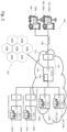
Fig. 1 shows the current state-of-the-art to exchange the information described above. -
Trains 100, which can be individualized astrains Fig. 1 shows that the ATO-OB 105a of the train 100a connects to one specific local ATO-TS 115, in particular to the ATO-TS 115a, based on a "train running number" and a specific access point name 120, in particular the access point name 120a. The term "subset 126" describes the communication interface according to European standardization. Each APN 120, each ATO-TS 115, and each TMS 110 has its own destination address that needs to be supplied to the "ATO-OB" 105 in order to be able to communicate with the correct TMS 110 of the respective driving area the train currently passes through. - Hence, the connection and service of the respective ATO-OB 105 is constrained by the geographical area that is covered by a single ATO-TS 115 and its connected TMS 110 service. For example, the first train 100a is connected to the TMS 110a that has information about journey profiles of the driving area around "Munich", wherein the
third train 100c is connected to the TMS 110c that has information about journey profiles of the driving area "Stuttgart". If thetrain 100 enters a different TMS 110 driving area, typically a different ATO-TS 115 is required because every TMS 110 is only connected to single ATO-TS 115. This requires a reconnection of the ATO-OB 105 to the different APN 120 with a different communication address . The handover procedures are not defined in advance so that is not possible to change automatically and seamlessly between different ATO-TS 115 and ATO-OB 105 combinations. One reason is that the various ATO-TS 115 are deployed on local servers or local data centers that do not allow scalability for hundreds or even thousands of trains connected to the system at the same time. - Currently, the ATO-TS 115 is connected to the respective TMS 110 by using proprietary interfaces depending on the capabilities of the respective TMS 110. In this set up, a seamless railway operation across Europe using ATO-OB 105 for automation, would require strict configuration management, that means that all ATO-OBs 105 across the whole fleet for all operators would "always" have to know the latest configuration data for each of the APNs 120 and the respective ATO-TS 115 addresses and the corresponding assignment to the different geographical areas.
- In the view of above, it is an object of the present invention to provide techniques that enable an efficient communication of automatic rail vehicle operation units with local traffic management systems, in particular if the rail vehicle travels through different driving areas that are supported by different local traffic management systems.
- This object is solved by the features of the independent claims.
- The features of the various aspects of the invention described below or the various examples of implementation may be combined with each other, unless this is explicitly excluded or is technically impossible.
- The invention is to be understood that it can be applied to rail vehicles in general and is not restricted to trains. However, in the following the invention will be described in terms that are commonly used regarding trains. The person skilled in the art recognizes that the functionality of those units described with these terms have a field of application that is not restricted to trains, but to rail vehicles in general.
- According to a first aspect of the invention, a method is disclosed that provides a communication link between an automatic train operation onboard unit, in particular a so-called "ATO-OB", of a rail vehicle with a local traffic management system comprising the following steps:
- providing a common access point, in particular a so-called "APN", and a common switching center, in particular a so-called automatic-train-operation-trackside-unit "ATO-TS",
∘ the common access point is the access point of the common switching center, i.e. a technical device to communicate and to send data to the common switching center. The switching center is called a common switching center, as will be explained in further detail in the following, because it is designed to communicate with multiple trains and multiple local traffic management systems in parallel; the common access point and/or the common switching center have known communication addresses, which can be provided to other units in order to facilitate a communication link; the common switching center can be located within a cloud service (or another kind of data center) that is provided by a network to the communication provider; the common access point is configured to communicate with a cellular and/or a fixed line standards. In particular, the common access point can communicate with 4G, 5G or further standards, especially railway specific standards such as GSM-R or FRMCS, and forward the data to the common switching center; the common switching center can be a server unit that runs with dedicated algorithms; - providing multiple local traffic management systems, in particular so-called "TMS", that are configured to communicate with the common switching center;
- ∘ typically, those local traffic management systems are managed and run by local traffic authorities. The local traffic management system and/or the common switching center can be realized as being a server or being implemented on the same or a different server unit. The local traffic management systems are provided with knowledge about the railroad infrastructure of a defined driving area, in particular about the rails, rail profiles etc. The local traffic management systems receive information from rail vehicles traveling through their driving area and try to optimize the traffic routing for those rail vehicles; in particular they can generate appropriate time table and routing information for each rail vehicle and send them to the corresponding automatic train operation onboard unit of that rail vehicle via a common control center or via the ATO-TS so that the rail vehicle adapts his driving strategy accordingly; currently the actual driving commands are then typically generated by the automatic train operation onboard unit itself; nevertheless, in principle it could be possible that the local traffic management systems also generate and send driving commands for the automatic train operation onboard unit to execute;
- ∘ the local traffic management systems each have known communication addresses, in particular IP addresses (or names that can be resolved, e.g. by DNS) so that the common switching center is able to establish a communication link;
- providing an automatic train operation onboard unit within a rail vehicle that is configured to communicate with the common access point and/or the common switching center;
- ∘ the automatic train operation onboard unit can be configured to execute driving commands, in particular driving commands of the driving traffic management systems, and to adapt the driving commands to the train according time table and routing information, e.g. accelerate, drive with a constant velocity, de-accelerate, coast, etc.;
- ∘ the automatic train operation onboard unit can be configured to collect status information about the train and to generate data packets that comprise this status information;
- ∘ the automatic train operation onboard unit can communicate with the common switching center through the APN, in particular by sending the data packet with the status information to the APN and to receive JPs and SPs from local traffic management systems via the APN; In general, a central instance, in particular the local traffic management systems, provides the basic parameters the journey of the vehicle (JP & SP), the then ATO-OB calculates the travel commands independently based on these parameters (in conjunction with information from the onboard train control computer, which provides, for example, the position of the next signal indicating a stop).
- ∘ typically, the automatic train operation onboard unit can communicate by mobile communication standards, like 4G, 5G, GMS-R, FRMCS, or further standards; for that purpose, the automatic train operation onboard unit comprises a radio module and can have a SIM are an eSIM module that provides the mobile communications and comprises the communication address of the automatic train operating unit;
- ∘ typically, each ATO-OB is associated with a unique train ID and a unique train running number; Typically, the train driver enters this train running number into another onboard system at the start of the mission, and the ATO-OB uses this number to establish communication with the ATO-TS it knows and then requests information on JPs and SPs;
- The information about the current driving area, e.g. a geographical position of the train, can be used by the common switching center to redirect the communication to the appropriate local traffic management system. Also the train running Number can be used if no localization information can be provided, so that the common switching center queries the connected TMS which has information about this train. For that purpose, it is possible that the common switching center is being supplied with information which driving area is managed by each of the local traffic management systems and it is possible that the common switching center sends a kind of broadcast signal to the various local traffic management systems, wherein the current driving signal comprises information about the current driving area of the train and/or its train running number. Then the various local traffic management systems can evaluate if this information corresponds to their managed driving area. If one of the various local traffic management systems evaluates that this information corresponds to its managed driving area, it can signal to the common switching center to forward the communication of the ATO-OB to it. That is, the common switching center can act as a local ATO-TS, which is transparent for the ATO-OB and the local TMS.
- This has the effect that there is no need for the automatic train operation onboard unit "ATO-OB" to undergo the "complicated" hand-over processes from a first local ATO-TS1 to gain access to a first local traffic management system TMS1 to a second local ATO-TS2 to gain access to a second local traffic management system TMS2 when the train drives from the traffic area of the first TMS1 to the driving area of the second TMS2. There is no need that the ATO-OB needs to "know" the communication addresses of each of the various ATO-TS units and their appropriate communication protocol versions that can differ between the various ATO-TS and can change with time.
- The common ATO-TS henceforth provides a cloud service with the functionality of a standard interface to the ATO-OBs of the trains, wherein this interface is already being defined by European standards, i.e. UNISIG subset-126. This also covers the ability of future specifications. Moreover, the ATO-TS cloud service can fulfill all functional and non-functional requirements, especially but not limited to reliability, availability, maintainability and security.
- The ATO-TS cloud service provides a single point of contact for the ATO-OB independent on the operational area of the respective TMS. This is even possible for cross-border traffic within Europe. Hand-over procedures for different ATO-TS instances or re-connections for ATO-OB with different point of contact (e.g. APNs) are not required. It is also not required to design the ATO-OBs for multi-APN operations.
- In an embodiment, the common switching center accesses an internal or external database to determine the local traffic management systems that corresponds to the current driving area.
- The database can be designed like a lookup table. An algorithm implemented on the common switching center can determine the local traffic management system based on the information about the current driving position and extract the corresponding communication address of the TMS and forward the communication accordingly.
- In an embodiment, the common switching center and/or the multiple local traffic management systems have access to a merged driving area map, wherein the merged driving area map comprises information of the different driving areas.
- This provides the advantage that the common switching center can use information of the merged driving area map as described below and/or that the local traffic management systems can take additional information of border regions into account when generating the optimized parameters of the journey, namely the JPs and SPs. In particular, the merged driving area map comprises current traffic information of the driving areas. It follows that a first TMS can have the knowledge that a certain railroad of a second TMS cannot be used as planned, for example due to an accident, so that an early re-routing calculation is possible.
- Typically, the local traffic management systems only have map information of the driving area that they manage. Hence, this lacks information about the "overall" picture of all the driving areas together. However, if every TMS were to be equipped with such a map, this would consume a lot of memory resources and would be costly to download. Therefore, it is beneficial that the database of the merged driving area map is located within the coming switching center or at further "external" database. To enable an efficient upgrade process, each of the local traffic management systems is allowed to "replace" an old version of its corresponding driving area within the merged driving area map with a newer version of this driving area. This is especially efficient, because every local traffic management system has access to the newest version of its driving area.
- The merged driving map can comprise the following information
- so-called "connecting areas" or "transition areas", i.e. it is known, where a driving area starts and where another driving area ends;
- information about properties of the railroads of the various driving areas, e.g. switching points, gradients, stations, conditions of the railroads;
- off-line map information of the driving areas;
- Geographical information about the various driving areas; (GPS, off-line maps; and information which other driving area is neighboring at a certain border point);
- transition areas of neighboring driving areas;
- communication addresses and, if required APN, of the local traffic management system unit that corresponds to a certain driving area.
- This information allows the use of the merged driving map for a variety of use cases.
- Preferably, the merged driving area map is used as an off-line automatic-train-operation backup solution for a driving area if the respective local traffic management system is not accessible, wherein the common switching center generates the appropriate JPs and SPs for the automatic train operation onboard unit of the train. In particular, the common switching center can use the off-line-map data of the driving area of the non-accessible or malfunctioning TMS for those cases. It can happen that a local traffic management system cannot provide the ATO-OB with required information on segment profiles because the TMS in question is being malfunctioning or the communication link is broken. In that case. it is possible that a virtual driving management system is being implemented as an algorithm on the common switching center that extract properties of the driving area of the non-accessible or a malfunctioning TMS from the merged driving area map to generate the required optimized parameters of the train's trip and to send them to the corresponding ATO-OBs. It is even possible to back up the ATO-TS with a further ATO-TS, which is very efficient compared to backing up every single TMS.
- In an embodiment, the backup solution uses historical data of the driving areas of the not accessible local traffic management systems and/or current traffic data of neighboring driving areas to generate the JPs and SPs.
- This provides the effect that the off-line data can be combined with historical data in order to make a better guess on the actual current traffic situation of the driving area. Hence, historical data can show average data traffic for every day of the week resolved in a time interval of hours to account for daily and hourly variations. This information can even be combined with current traffic data of neighboring driving areas, which re-present an actual measurement that can show that the historical data is not that accurate for the current situation. If current data traffic of neighboring driving area shows that the train traffic is actually higher than expected due to the historical data, it is possible to scale the historical data accordingly and to account for the higher traffic volume. The described scenario could be the case, if in future embodiments of the invention, one or more TMS are virtualized within the common switching center. Currently, the common switching center is not allowed to "overrule" decisions of the various TMS. Currently, based on historical data, the common switching center can estimate how traffic will develop, whether the train will be on time and can transmit this information back to the TMS. This corresponds to a delay management based on prediction, which does not wait until it is actually too late.
- In an embodiment, a handover process from a first local traffic management system, in particular TMS1, to a second local traffic management system, in particular TMS2, is triggered by the common switching center if the rail vehicle travels from the driving area of the first local traffic management system to the driving area of the second local traffic management system. In particular, the handover process can be a seamless handover process, wherein the common switching center provides the TMS and the ATO-OB for the respective communication addresses.
- A following local traffic management system, in particular the next local traffic management system, can be determined by using information of a journey plan. The journey plan is available at the common switching center and was created at the beginning of the journey, provided through information of the TMS in the starting area.
- This provides the effect that the ATO-OB of the train has always an established communication with the appropriate TMS.
- In an embodiment, the triggering of the handover process is based on the following information:
- position and/or velocity information of the rail vehicle provided by the automatic train operation onboard unit,
- automatic train operation unit status report information provided by the automatic train operation onboard unit, and/or
- the merged driving area map.
- This provides the advantage that the hand-over process to the appropriate TMS can be initiated efficiently when the train enters another driving area.
- In an embodiment, the second local traffic management system is notified in advance about the expected entrance of a rail vehicle in its driving area. The expected arrival time in the driving area of the second local traffic management system can be calculated by the information that trigger the hand over process. By notifying the second local traffic management system that the train will enter its region at the expected time, it is possible that the second TMS already takes the new incoming train into account when performing route optimization calculations. In an embodiment, the second TMS is being notified 10 minutes, in particular 5 minutes before the expected entrance time of the train in its driving area.
- In an embodiment, the communication between the automatic train operation onboard unit and the common switching center is performed event-based and/or on in regular time intervals as defined by Subset-126.
- The regular time intervals can be set in order to ensure that the communication network, common switching unit and/or the respective TMS units do not suffer from overload when possibly hundreds of thousands of trains communicate with these units, respectively. On the other hand, the frequency of the regular time intervals needs to be high enough to ensure the automatic driving operation of the trains.
- A further reduction of the data traffic and the calculation load is possible if the communication is performed based on well-defined events. The basic idea of this feature is that "if nothing changes" the train can continue with its current driving comments and there is only a need further communication if something "new" happens. Possible events are if the train approaches another driving area, if railroad traffic has increased and the respective TMS has calculated that the train needs to adapt its speed, if the automatic train onboard unit has calculated a (updated) deviation for the estimated arrival time, and/or if an accident or some kind of malfunctioning has occurred.
- In an embodiment, a common security standard is being applied to the communication between the automatic train operation unit and the common switching center.
- This provides the effect that the security of the overall system can be increased. In the discussed state-of-the-art system with the various ATO-TS and APN units it is very hard to establish a current security standard and to upgrade security measures accordingly and at the same time.
- In an embodiment, the common switching center provides a protocol translator functionality. The protocol translator functionality can convert protocols of data packets from the various automatic train operation onboard units to the appropriate protocols of the respective local traffic management system and vice versa.
- The protocol translator functionality can be implemented as hardware on the common switching center or as software in the form of a virtual protocol translator. Especially, the virtual protocol translator has the advantage that it can easily be adapted if interfaces, hardware, data types, operating systems and/or software versions change. As all the data packets pass the common switching center, this is very beneficial location for a protocol converter functionality. This feature is especially advantageous for system migration issues as it is often the case that new hardware or complex interfaces cannot be implemented at once. So it is possible to replace a TMS with a newer version and take this exchange into account within the protocol converter. Hence, this provides the advantage of a very flexible system.
- Preferably, the first local traffic management system, in particular the TMS1, and the second local traffic management system, in particular, the TMS2, are substituted by a common local traffic management system, in particular TMS1,2, that takes over the tasks of the first and the second local traffic management system. Finally, this could result into in the aforementioned merged driving area map that is only managed by a single TMS and/or the common switching center.
- This provides the advantage that all the necessary information is within one traffic management system which increases the efficiency of calculating route optimizations for all trains.
- According to a second aspect of the invention, a common switching center is disclosed, wherein the common switching center is configured to provide a communication link between an automatic train operation onboard unit of a rail vehicle with a local traffic management system, comprising:
- an communication interface, in particular according to Subset-126,
- wherein the communication interface is designed to exchange data with local traffic management system through a single access point,
- a switching algorithm implemented on a server of the common switching center, wherein the switching algorithm is configured:
- to analyze information received from the automatic train operation onboard unit about the current driving area of its train, wherein the common switching center receives this information via the APN,
- to determine a local traffic management system that manages the respective driving area and to extract the communication address of the respective local traffic management system;
- to provide the communication interface with the communication address of the respective local traffic management;
- The common switching center basically provides the advantages described above in the context of the method of the invention.
- According to a third aspect of the invention, a communication system for automated driving of rail vehicles is disclosed, wherein the system comprises:
- an automatic train operation onboard unit of a train;
- an access point that is configured to establish communication from automatic train operation onboard units to a common switching center;
- a common switching center as described above;
- local traffic management systems;
- a communication network that links the automatic train operation onboard unit to the APN, the APN to the common switching center, and the common switching center to the local traffic management systems;
- The communication system for automated driving of rail vehicles, in particular trains, basically provides the advantages described above in the context of the method of the invention.
- In the following, preferred implementation examples of the present invention are explained with reference to the accompanying figures:
- Fig. 1:
- shows an exemplary state-of-the-art communication system for automated driving of trains;
- Fig. 2:
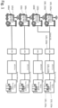
- shows the communication system for automated driving of rail vehicles, in particular trains, according to the invention;
- Fig. 3:
- shows a method according to the invention.
- In the following, numerous features of the present invention are explained in detail by means of preferred embodiments. The present disclosure is not limited to the specifically named combinations of features. Rather, the features mentioned here can be combined arbitrarily into inventive embodiments, unless this is expressly excluded below.
-
Fig. 2 shows acommunication system 150 for automated driving of rail vehicles in which each automatic train operation onboard unit 105 (i.e. ATO-OB 105a and 105b) that can be operated by arbitrary railway undertakings (e.g. OBB, DB) has only a single point ofcontact 122, which comprises an address of anAPN 121 and an address of a common switching center 116 (a ATO-TS 116 cloud service). - When a
train 100, which is equipped with the ATO-OB 105a, runs from a first driving area 105a that is managed by a first local traffic management system 135a, e.g. TMS1 135a, area to asecond driving area 105b that is managed by a second localtraffic management system 135b,e.g. TMS 2 135b, the ATO-OB 105a can still use the connection to the same ATO-TS 116 cloud service through thesame APN 121. Acommunication link 130 between theAPN 121 and the ATO-OB 105a is typically designed to be a radio connection (4G, 5G, 6G, ...). Communication links that are logically after theAPN 121 in direction of the ATO-TS 116 can be made of a radio connection, of a fixed line connection or can be designed as a mixture of both communication techniques. - In case of a change of the
first driving area 110a that is managed by the first TMS1 135a to thesecond driving area 110b that is managed by thesecond TMS 2 135b, the ATO-TS 116 will automatically connect to theTMS 2 135b, which can be completely transparent for the ATO-OB 105a. - The ATO-
TS 116 can use the following information to trigger a handover process between the different TMS 135a-d systems: - the ATO-OB status report information (Subset-126, packet 8) that provides information about the current position of the vehicle/train, its velocity, and its estimated arrival time for the upcoming timing points or skipping points;
- configuration about neighborhood relations of neighboring TMS systems;
- information from different TMS 135a-d systems to manage the transparent handover between
different driving areas 110a-d. That is, the train 100a operating on a specific route (or journey profile) has its unique train running number that does not change when entering a new driving area. Once the train approaches the boundary of its currently assigned driving area, the ATO-TS 116 cloud service can identify that event by evaluating the positioning information of the ATO-OB 105a status reports as well as through a prediction of the arrival times for certain timing/skipping points provided by the ATO-OB 110a. - Hence, the ATO-
TS 116 cloud service can identify the "neighboring" TMS system and can connect to that one. Information about neighboring TMS system can be stored as a database on the ATO-TS 116. - The ATO-
TS 116 cloud service can connect to multiple TMS 135a-d systems in parallel, i.e. keeping the service for the train 100a operating in the first TMS 135a area running while preparing the arrival into thenext TMS 135b area already in advance. That is, based on the same train running number, the ATO-TS 116 cloud service can already request the following journey profile information from the TMS 135 system for the next driving area 110 in order to provide the "new" journey profile to the ATO-OB 110a at an early stage. Once the train 100a with the ATO-OB 105a approaches the boundary of thedriving area 110a managed by the first TMS1 135a, the ATO-TS 116 can arrange the handover between different TMS 135a-d systems based on a dedicated business logic, e.g. available train running number, available timetable information from all TMS systems, and others. The ATO-OB 105a remains connected to the same ATO-TS 116 through thesame APN 121 all the time. - Once the vehicle/train 100a has entered the driving
area 110b operated by a "new"TMS 135b the connection to the previous TMS 135a and the ATO-OB 105a can be closed. - Scalability for parallel connection of hundreds and thousands of trains is possible for the
communication system 150 according to the invention simply by increasing computational power and/or the APNs 115 capacities. - The ATO-
TS 116 requires at most one interface connection to the different TMS 135a-d systems. In case the rollout of ATO-OB 105 systems proceeds, scalability of the ATO-TS 116 can simply be achieved by adding additional computation power. No additional or separate ATO-TS 116 on dedicated hardware will be required, but it is possible to implement an additional ATO-TS 116 for reasons of redundancy. Moreover, theTMS 116 do not require frequent upgrades of their base system, e.g. hardware, as the need to serve only a single interface to the ATO-TS 116. In addition, compatibility issues between the TMS 135a-d, the ATO-OB 105 and/or the ATO-TS 116 can be solved by implementing a protocol translator 140 (that can also be called a protocol converter 140) within the ATO-TS 116. Theprotocol converter 140 can be implemented as a software and/or hardware solution. - Moreover, there are synergies with respect to the amount of data requested by the ATO-
TS 116 from different TMS 135 systems. That is, not each segment profile needs to be repeatedly requested from different TMS 135 systems but the ATO-TS 116 can use a track database of specific segment profiles, wherein updates are only requested by the ATO-TS 116 from the TMS 135 if a version information has changed. - The ATO-
TS 116 can realize a set of proprietary interfaces to the various TMS 135 systems. These proprietary interfaces can either be hosted within the same cloud environment as the ATO-TS 116 or in a different network environment. The ATO-TS 116 can access these local TMS 135 systems, owned and operated by different legal entities through secured interfaces ensuring data security, data integrity and freedom of interference between the neighboring TMS 135. The ATO-TS 116 can either realize standard interfaces (to be defined within Technical Specification for Interoperability) or proprietary interfaces, it is possible to perform appropriate "translations" by theprotocol converter 140. It is to be expected that the proprietary interface option will be more common in the upcoming years. In terms of security, the ATO-TS 116 cloud service shall realize measures according to IEC 62443 and/or TS50701. According to the capabilities of TMS 135 systems, which might have reached their end of life, full scope security measure might not be possible. The ATO-TS 116 service can adapt, in particular by using theprotocol converter 140, to available security measures for that specific TMS 135 system. - The following additional services that can be added for significant additional value:
Information of reportingtrains 100, i.e. trains 100 that report their status information (speed, location, etc.), can already be provided to any TMS 135 that might be concerned even if the reporting ATO-OB 105a is not yet with thecorresponding driving area 110b. E. g., on delayed departure, the ATO-OB 105a can already report delays and ATO-TS 116 can forward these statuses to all involved TMS systems up to the destination which provides additional information for planning and operation. The involved TMS systems can be assess amerged driving map 170 of all driving areas and/or a traveling plan of the train. -
Fig. 2 also shows an exemplary embodiment of themerged driving map 170 that can be implemented within the ATO-TS 116 and/or can be in data connection with the ATO-TS 116. Themerged driving map 170 can provide at least information which areas are mutually adjacent and/or the corresponding TMS 135 of each driving area 110. - In case an interface to the local TMS 135a system is not available, e.g. the TMS supplier cannot update the system/software, then the ATO-
TS 116 can operate based on offline segment profile data (track database) and timetable information to generate JPs and SPs. Deviations from default routes and/or default timetables can still be exchanged with other TMS 135. Moreover, as the cloud service has also connection to neighbouring TMS areas it is possible to provide JPs and SPs taking that information, e.g. through AI, into account. - The ATO-
TS 116 provides simple migration when several TMS 135 areas are combined, TMS interfaces are updated and if the TMS is established as cloud service. - It is also possible to apply adhesion management. The ATO-
TS 116 can receive current status of adhesions conditions, i.e. slip and/or slide information during traction and/or braking, from all reporting trains operating equipped with the ATO-OB 105. The information directly affects the train's capabilities of acceleration and deceleration and, hence, the required travel time. Based on the ATO-TS 116, this information cannot only be provided to the local TMS but to all trains that are planned to travel through that TMS area but are currently still moving within a different TMS area. Same holds for reporting to different TMS areas for updated prediction of traveling times and delays. - The ATO-
TS 116 can directly provide information of reporting trains to mobility data platforms, e.g. according to German and other national and/or European regulations. -
Fig. 3 shows amethod 200 to provide a communication link between the automatic train operation unit 105 of the train 100a with the appropriate local traffic management system 135 comprising the following steps: - step: 205: providing the
common access point 121 and thecommon switching center 116, - step 210: providing local traffic management systems 135 that are configured to communicate with the
common switching center 116 and/or can are configured to directly communicate with each other; - step 215: providing an automatic train operation onboard unit 105 within a rail vehicle that is configured to communicate with the common access point;
- step 220: the automatic train operation onboard unit 105 transmits information at least about its current driving area when communicating with the common access point, wherein the common switching center forwards the communication of the automatic train operation onboard unit to the local traffic management system that corresponds to the current driving area.
- As a summery, the invention provides at least: i) compatibility with the European standardization, ii) the different national and organizational rules for security can be provided through proper data center or cloud setup, iv) the cloud service does not require real time services and does not afford an environment that is optimised regarding latency, iv) the cloud service is not constrained by any regulation w.r.t. functional safety.
Claims (15)
- A method to provide a communication link between an automatic train operation unit (105), in particular a so-called "ATO-OB" (105), of a rail vehicle (100) with a local traffic management system (135) comprising the following steps:• providing a common access point (121), in particular a so-called "APN" (121), and a common switching center (116), in particular a so-called automatic-train-operation-trackside-unit "ATO-TS" (116),• providing local traffic management systems (135a-d), in particular so-called "TMS" (135a-d), that are configured to communicate with the common switching center (116);• providing an automatic train operation onboard unit (105) within a rail vehicle (100) that is configured to communicate with the common access point (121);wherein the automatic train operation onboard (105) unit transmits information at least about its current driving area (110) when communicating with the common access point (121), wherein the common switching center (116) forwards the communication of the automatic train operation onboard unit (105) to the local traffic management system (135) that corresponds to the current driving area (110).
- The method of any of the claims, wherein the common switching center (116) accesses an internal or external database to determine the local traffic management system (135a-d) that corresponds to the current driving area (110a-d).
- The method of any of the claims, wherein the common switching center (116) and/or the multiple local traffic management systems (135a-d) have access to a merged driving area map (170), wherein the merged driving area map (170) comprises information of the different driving areas (110a-d).
- The method of claim 3, wherein the information of the merged driving area map (170) comprises• information about properties of the railroads of the various driving areas;• geographical information about the various driving areas;• transition areas of neighboring driving areas; and/or• communication addresses of the local traffic management system unit that corresponds to a certain driving area.
- The method of any of the claims 3 to 4, wherein the merged driving (170) area is used as an off-line automatic-train-operation backup solution for a driving area (110a-d) if the respective local traffic management system is not accessible (135a-d), wherein the common switching center (116) generates the appropriate journey profiles for the automatic train operation onboard unit (105) of the train.
- The method of claim 5, wherein the backup solution uses historical data of the driving areas (110a-d) of the not accessible local traffic management systems (135a-d) and/or current traffic data of neighboring driving areas to generate the journey profiles.
- The method of any of the claims, wherein a handover process from a first local traffic management system (135a), in particular TMS1 (135a), to a second local traffic management system (135b), in particular TMS2 (135b), is triggered by the common switching center (116) if the rail vehicle (100) travels from the driving area (110a) of the first local traffic management system (135a) to the driving area (110b) of the second local traffic management system (135b).
- The method of the claims 3 and/or 7, wherein the triggering of the handover process is based on the following information:• GPS location information of the rail vehicle provided by the automatic train onboard operation unit (105),• automatic train operation onboard unit (105) status report information provided by the automatic train operation onboard unit (105), and/or• the merged driving area map (170).
- The method of the claims 7 to 8, wherein a second local traffic management system (135b) is notified in advance about the expected entrance of a rail vehicle (100) in its driving area (110b).
- The method of any of the claims, wherein the communication between the automatic train operation onboard unit (105) and the common switching center (116) is performed event-based and/or on in regular time intervals.
- The method of any of the claims, wherein a common security standard is being applied to the communication between the automatic train operation unit (105) and the common switching center (116).
- The method of any of the claims, the common switching center (116) provides a protocol translator functionality.
- The method of any of the claims, wherein the first local traffic management system (135a), in particular the TMS1 (135a), and the second local traffic management system (135b), in particular, the TMS2 (135b), are substituted by a common local traffic management system, in particular TMS1,2, that takes over the tasks of the first and the second local traffic management system.
- A common switching center to provide a communication link between an automatic train operation onboard unit of a rail vehicle with a local traffic management system, comprising:an communication interface, wherein the communication interface is designed to exchange data with local traffic management system (135) and with a common access point (121),a switching algorithm implemented on a server (140) of the common switching center (116), wherein the switching algorithm is configured:wherein the communication interface is designed to forward the data of the automatic train operation onboard unit (105) to the respective local traffic management (135a-d).• to analyze information received from the automatic train operation unit (105) about the current driving area of its train (110), wherein the common switching center (116) receives this information via the APN (121),• to determine a local traffic management system (135a-d) that manages the respective driving area (110a-d) and to extract the communication address of the respective local traffic management system (135a-d);• to provide the communication interface with the communication address of the respective local traffic management (135a-d);
- A communication system for automated driving of rail vehicles comprising:• an automatic train operation onboard unit (105) of a train (100);• an access point (121) that is configured to communicate with automatic train operation onboard units (105a-d) and with a common switching center (116);• a common switching center (116) according to claim 14;• local traffic management systems; (135a-d)• a communication network that links the automatic train operation onboard unit (105) to the APN (121), the APN (121) to the common switching center (116), and the common switching center (116) to the local traffic management systems (135a-d);wherein the communication system is being configured to execute the steps of the method according to the claims 1 to 13.
Priority Applications (1)
| Application Number | Priority Date | Filing Date | Title |
|---|---|---|---|
| EP22190176.2A EP4321410A1 (en) | 2022-08-12 | 2022-08-12 | Communication system for automated rail vehicle driving operations |
Applications Claiming Priority (1)
| Application Number | Priority Date | Filing Date | Title |
|---|---|---|---|
| EP22190176.2A EP4321410A1 (en) | 2022-08-12 | 2022-08-12 | Communication system for automated rail vehicle driving operations |
Publications (1)
| Publication Number | Publication Date |
|---|---|
| EP4321410A1 true EP4321410A1 (en) | 2024-02-14 |
Family
ID=82898899
Family Applications (1)
| Application Number | Title | Priority Date | Filing Date |
|---|---|---|---|
| EP22190176.2A Pending EP4321410A1 (en) | 2022-08-12 | 2022-08-12 | Communication system for automated rail vehicle driving operations |
Country Status (1)
| Country | Link |
|---|---|
| EP (1) | EP4321410A1 (en) |
-
2022
- 2022-08-12 EP EP22190176.2A patent/EP4321410A1/en active Pending
Non-Patent Citations (5)
| Title |
|---|
| ANONYMOUS: "ATO-OB / ATO-TS FFFIS Application Layer", USING, no. 0.0.16, 7 May 2018 (2018-05-07), pages 1 - 36, XP093135702 * |
| GERD TASLER ET AL: "Einführung des hochautomatisierten Fahrens - auf dem Weg zum vollautomatischen Bahnbetrieb - The introduction of highly automatic operation - towards fully automatic train operation", SIGNAL UND DRAHT: SIGNALLING & DATACOMMUNICATION, vol. 110, no. 6, 12 June 2018 (2018-06-12), DE, pages 6 - 14, XP055487244, ISSN: 0037-4997 * |
| SCHRÖDER JAN ET AL: "Digitale S-Bahn Hamburg", 1 October 2021 (2021-10-01), XP093225203, Retrieved from the Internet <URL:https://s-bahn.hamburg/magazin/wp-content/uploads/2021/10/44_47_Schroeder_etal.pdf> [retrieved on 20241118] * |
| SUWALSKI IRENEUS ET AL: "ATO over ETCS as the key to greater efficiency, capacity and sustainability - practical experience and strategies", 1 September 2021 (2021-09-01), pages 13 - 24, XP055964110, Retrieved from the Internet <URL:https://assets.new.siemens.com/siemens/assets/api/uuid:72b071ba-5fba-4819-8f73-bb64443e4e25/sd-ato-over-etcs-suwalski-wuensche-09-2021.pdf> [retrieved on 20220923] * |
| VILLALBA MANUEL: "Pioneering ATO over ETCS Level 2", 1 September 2016 (2016-09-01), pages 107 - 109, XP093018078, Retrieved from the Internet <URL:https://www.unife.org/wp-content/uploads/2021/03/Pioneering-ATO-over-ETCS-Level-2-Railway-Gazette.pdf> [retrieved on 20230126] * |
Similar Documents
| Publication | Publication Date | Title |
|---|---|---|
| US12570340B2 (en) | Rail transit signal system with multi-network integration | |
| US10518790B2 (en) | Wireless train management system | |
| AU2019284070B2 (en) | Cyber security anonymizer | |
| CN110126883B (en) | Planning method and on-board controller for train travel path | |
| CN110126882B (en) | Train control method and system and calculation method of movement authorization | |
| US20160016598A1 (en) | Device for interfacing railway driver advisory system | |
| US20110172856A1 (en) | Short Headway Communications Based Train Control System | |
| EP1598985A1 (en) | Intelligent wireless network switching | |
| CN109532955B (en) | Micro-rail scheduling control method and system | |
| RU2529582C2 (en) | Method of transmitting alarm data between railroad car involved in accident and control centre and corresponding device | |
| CN110001716A (en) | A kind of control method and system of column control equipment control car data switching | |
| EP3696046A1 (en) | System and a method for managing traffic of a railway line | |
| CN114620100B (en) | CBTC signal system based on cloud technology | |
| KR102070397B1 (en) | Method for operating a packet based communication network in a railway system | |
| CN114889673A (en) | Train control system and train control method | |
| Palumbo | Railway Signaling since the Birth to ERTMS | |
| CN118439079A (en) | Driving handover area optimization configuration method of train control system | |
| CN120018231A (en) | Train communication method and system | |
| Matsumoto et al. | Assurance technologies for autonomous train on-board computer system | |
| JP7374378B2 (en) | train control system | |
| CN117465518A (en) | Switching method of railway train double-system control system | |
| JP2021517087A (en) | A method for scheduling or controlling the movement of multiple vehicles on a route network | |
| CN114426043A (en) | Transponder message sending method and system for improving running efficiency in train station | |
| Chen et al. | Incremental train control system of Qinghai–Tibet railway | |
| Schnieder | Perspectives and Future Challenges |
Legal Events
| Date | Code | Title | Description |
|---|---|---|---|
| PUAI | Public reference made under article 153(3) epc to a published international application that has entered the european phase |
Free format text: ORIGINAL CODE: 0009012 |
|
| STAA | Information on the status of an ep patent application or granted ep patent |
Free format text: STATUS: REQUEST FOR EXAMINATION WAS MADE |
|
| 17P | Request for examination filed |
Effective date: 20230707 |
|
| AK | Designated contracting states |
Kind code of ref document: A1 Designated state(s): AL AT BE BG CH CY CZ DE DK EE ES FI FR GB GR HR HU IE IS IT LI LT LU LV MC MK MT NL NO PL PT RO RS SE SI SK SM TR |
|
| STAA | Information on the status of an ep patent application or granted ep patent |
Free format text: STATUS: EXAMINATION IS IN PROGRESS |
|
| 17Q | First examination report despatched |
Effective date: 20241125 |