EP4321296A1 - Improved sanding machine - Google Patents
Improved sanding machine Download PDFInfo
- Publication number
- EP4321296A1 EP4321296A1 EP23189942.8A EP23189942A EP4321296A1 EP 4321296 A1 EP4321296 A1 EP 4321296A1 EP 23189942 A EP23189942 A EP 23189942A EP 4321296 A1 EP4321296 A1 EP 4321296A1
- Authority
- EP
- European Patent Office
- Prior art keywords
- roll
- abrasive belt
- roller
- sanding
- sanding machine
- Prior art date
- Legal status (The legal status is an assumption and is not a legal conclusion. Google has not performed a legal analysis and makes no representation as to the accuracy of the status listed.)
- Pending
Links
- 239000000919 ceramic Substances 0.000 claims abstract description 5
- 239000002131 composite material Substances 0.000 claims abstract description 5
- 229910052751 metal Inorganic materials 0.000 claims abstract description 5
- 239000002184 metal Substances 0.000 claims abstract description 5
- 238000011017 operating method Methods 0.000 claims abstract description 5
- 239000004033 plastic Substances 0.000 claims abstract description 5
- 239000002023 wood Substances 0.000 claims abstract description 5
- 239000004576 sand Substances 0.000 claims abstract description 3
- 239000013536 elastomeric material Substances 0.000 claims description 4
- 239000000835 fiber Substances 0.000 claims description 3
- 238000003780 insertion Methods 0.000 claims description 3
- 230000037431 insertion Effects 0.000 claims description 3
- CNQCVBJFEGMYDW-UHFFFAOYSA-N lawrencium atom Chemical compound [Lr] CNQCVBJFEGMYDW-UHFFFAOYSA-N 0.000 description 15
- 238000000034 method Methods 0.000 description 7
- 230000008901 benefit Effects 0.000 description 4
- 230000032258 transport Effects 0.000 description 4
- 239000011347 resin Substances 0.000 description 3
- 229920005989 resin Polymers 0.000 description 3
- 230000005540 biological transmission Effects 0.000 description 2
- 239000008187 granular material Substances 0.000 description 2
- 238000009499 grossing Methods 0.000 description 2
- 230000008569 process Effects 0.000 description 2
- 238000005299 abrasion Methods 0.000 description 1
- 239000006061 abrasive grain Substances 0.000 description 1
- 238000004873 anchoring Methods 0.000 description 1
- 229920006231 aramid fiber Polymers 0.000 description 1
- 230000008859 change Effects 0.000 description 1
- 239000004744 fabric Substances 0.000 description 1
- 238000003754 machining Methods 0.000 description 1
- 239000000463 material Substances 0.000 description 1
- 238000012986 modification Methods 0.000 description 1
- 230000004048 modification Effects 0.000 description 1
- 229920001778 nylon Polymers 0.000 description 1
- TWNQGVIAIRXVLR-UHFFFAOYSA-N oxo(oxoalumanyloxy)alumane Chemical compound O=[Al]O[Al]=O TWNQGVIAIRXVLR-UHFFFAOYSA-N 0.000 description 1
- RVTZCBVAJQQJTK-UHFFFAOYSA-N oxygen(2-);zirconium(4+) Chemical compound [O-2].[O-2].[Zr+4] RVTZCBVAJQQJTK-UHFFFAOYSA-N 0.000 description 1
- 239000002245 particle Substances 0.000 description 1
- 238000005498 polishing Methods 0.000 description 1
- HBMJWWWQQXIZIP-UHFFFAOYSA-N silicon carbide Chemical compound [Si+]#[C-] HBMJWWWQQXIZIP-UHFFFAOYSA-N 0.000 description 1
- 229910010271 silicon carbide Inorganic materials 0.000 description 1
- 230000003245 working effect Effects 0.000 description 1
- 229910001928 zirconium oxide Inorganic materials 0.000 description 1
Images



Classifications
-
- B—PERFORMING OPERATIONS; TRANSPORTING
- B24—GRINDING; POLISHING
- B24B—MACHINES, DEVICES, OR PROCESSES FOR GRINDING OR POLISHING; DRESSING OR CONDITIONING OF ABRADING SURFACES; FEEDING OF GRINDING, POLISHING, OR LAPPING AGENTS
- B24B21/00—Machines or devices using grinding or polishing belts; Accessories therefor
-
- B—PERFORMING OPERATIONS; TRANSPORTING
- B24—GRINDING; POLISHING
- B24B—MACHINES, DEVICES, OR PROCESSES FOR GRINDING OR POLISHING; DRESSING OR CONDITIONING OF ABRADING SURFACES; FEEDING OF GRINDING, POLISHING, OR LAPPING AGENTS
- B24B21/00—Machines or devices using grinding or polishing belts; Accessories therefor
- B24B21/04—Machines or devices using grinding or polishing belts; Accessories therefor for grinding plane surfaces
- B24B21/12—Machines or devices using grinding or polishing belts; Accessories therefor for grinding plane surfaces involving a contact wheel or roller pressing the belt against the work
-
- B—PERFORMING OPERATIONS; TRANSPORTING
- B24—GRINDING; POLISHING
- B24B—MACHINES, DEVICES, OR PROCESSES FOR GRINDING OR POLISHING; DRESSING OR CONDITIONING OF ABRADING SURFACES; FEEDING OF GRINDING, POLISHING, OR LAPPING AGENTS
- B24B21/00—Machines or devices using grinding or polishing belts; Accessories therefor
- B24B21/18—Accessories
-
- B—PERFORMING OPERATIONS; TRANSPORTING
- B24—GRINDING; POLISHING
- B24B—MACHINES, DEVICES, OR PROCESSES FOR GRINDING OR POLISHING; DRESSING OR CONDITIONING OF ABRADING SURFACES; FEEDING OF GRINDING, POLISHING, OR LAPPING AGENTS
- B24B7/00—Machines or devices designed for grinding plane surfaces on work, including polishing plane glass surfaces; Accessories therefor
- B24B7/005—Portal grinding machines
-
- B—PERFORMING OPERATIONS; TRANSPORTING
- B24—GRINDING; POLISHING
- B24B—MACHINES, DEVICES, OR PROCESSES FOR GRINDING OR POLISHING; DRESSING OR CONDITIONING OF ABRADING SURFACES; FEEDING OF GRINDING, POLISHING, OR LAPPING AGENTS
- B24B7/00—Machines or devices designed for grinding plane surfaces on work, including polishing plane glass surfaces; Accessories therefor
- B24B7/06—Machines or devices designed for grinding plane surfaces on work, including polishing plane glass surfaces; Accessories therefor involving conveyor belts, a sequence of travelling work-tables or the like
Definitions
- the present invention relates to an improved sanding machine, in particular a sanding machine comprising an abrasive belt replacement assembly.
- the invention relates to a sanding machine comprising a replacement assembly for an abrasive belt, designed and manufactured in particular to support the abrasive belt which has to be replaced in a sanding machine.
- Some sanding machines are equipped with sanding belt sanding units closed in a loop, arranged around two or more cylindrical rollers, and possibly around a pad, for sanding moving parts in one feed direction.
- Said sanding machines generally comprise a transport device, for moving the pieces, a frame, a supporting column, a motor unit, a transverse upright, at least one operating roller, an idle roller, a pneumatic actuator for stretching the abrasive belt.
- the supporting column is the element through which the sanding unit is coupled to the machine frame.
- the motor unit having a motor, a pulley, and a disc brake, and the transversal upright, on which in its turn the operating roller is installed.
- the operating roller is driven by the motor, by means of a transmission generally of the belt type.
- the cross upright is a structural element that extends horizontally above the operating roller and supports it by means of two vertical shoulders placed at the end of the cross upright itself.
- the pneumatic actuator for stretching the abrasive belt, arranged so as to have a base on the transverse upright, comprises a cylinder and a piston equipped with a rod, and supports, at the end of the rod, a cross member with an idle roller, the whose function is to keep the abrasive belt in tension.
- the sanding unit can also comprise a second operating roller, powered in the same way as the first, and a flat-shaped pad, placed between the two operating rollers, to increase the contact surface between the abrasive belt and the piece.
- Abrasive belts generally have a fabric support, an anchoring resin for the abrasive, in which the abrasive granules are immersed, i.e., particles having a certain degree of angularity, of highly hard materials, such as zirconium oxide, aluminum oxide, silicon carbide, and finally a resin covering the granules.
- the sanding process of the pieces causes the loss of part of the covering resin in the abrasive belt and the flattening of the sharp edges of the abrasive grains, to the point where the abrasive belt is so worn that it is no longer able to penetrate the piece to perform the workings.
- auxiliary equipment has a base plane coupled to wheels, a vertical upright and a transverse element, slidably coupled to the vertical upright, so that the distance of said transverse element from the base plane can be adjusted, a locking element of the cross member on the vertical post.
- the auxiliary equipment is manually approached to the sanding machine, and the distance of the transversal element from the base plane is then adjusted, according to the height above the ground of the top of the closed ring formed by the abrasive belt.
- the auxiliary equipment is therefore positioned on the side of the sanding machine set up for the belt change, which is generally the one opposite the side where the motor is present.
- the belt is made to slide by operators on the cross element in such a way as to be supported by the latter. The procedure for inserting the new abrasive belt takes place in the same way.
- Another scope of the invention is to provide an improved sanding machine comprising a replacement assembly for replacing the abrasive belt, without using auxiliary equipment external to the machine.
- a further scope of the present invention is to speed up the replacement of the abrasive belt in a sanding machine.
- a Machine for sanding pieces made of wood, metal, ceramic, plastic, composite materials and the like comprising: a frame; and at least one sanding unit, installed on said frame, comprising in turn at least a first motorized operating roller, an idle roller, and an abrasive belt, arranged so as to form a closed loop, around said first operating roller and said idle roller, to sand a surface of a piece to be sanded, movable with respect to said sanding unit; characterized in that it comprises a replacement assembly, coupled to said frame, comprising a support member, and a roll-up element, coupled to said support member, wherein said support member is capable of assuming a retracted position, in which said roll-up element is rolled, and an extracted position, in which said roller shutter element is extended, and wherein said roll-up element is capable of supporting, in said extracted position, said abrasive belt, when it is removed from said first operating roller and from said
- said replacement assembly may be arranged inside said closed loop formed by said abrasive belt.
- said roll-up element may have one end fixed at said idle roller.
- said sanding machine may comprise guiding means, fixed to said support member and to said frame.
- said guiding means may be telescopic.
- said roll-up element may be a tape, which in said rolled position is rolled up on itself in the form of a reel.
- said roll-up element may be made of polymeric fiber.
- said roll-up element may have an upper layer made of elastomeric material or PVC and is able to drag with it, by friction, said abrasive belt when said roll-up element is made to pass from said rolled position to said extended position.
- said sanding machine may comprise an input station, for the insertion of said pieces to be machined, an output station, for the output of said pieces, and a conveyor device, to transport said workpieces from said input station to said output station.
- said sanding unit may comprise a second motorized operating roller, and said abrasive belt may be also arranged around said second operating roller.
- said sanding assembly may comprise a skid, and wherein said abrasive belt is also arranged around said skid.
- a replacement assembly which can be installed in a sanding machine, of the type having a sanding unit with at least one motorized first operating roller, an idle roller, an abrasive belt, arranged in a closed loop around said first operating roller and said idle roller, comprising: a support member; and a roll-up element, coupled to said support member, having one end that can be fixed in correspondence with said idle roller, movable between a rolled position and an extended position; wherein said roll-up element is able to support, in use, in said extended position, said abrasive belt when it is removed from said first operating roller and from said idle roller.
- said method may comprise the steps of: pulling said roll-up element so as to make it pass from said rolled position to said extended position, dragging said abrasive belt with it by friction, removing said abrasive belt from said roll-up element.
- said method may further comprise the steps of: inserting an abrasive belt, closed in a loop around said roll-up element, when this is in said extended position, in such a way that said roll-up element supports said abrasive belt; transferring said abrasive belt into said sanding unit so as to arrange it closed in a ring around said first operating roller and said idle roller; and pushing said roll-up element so as to make it pass from said extended position to said rolled position.
- the attached figures show a sanding machine M for pieces made of wood, metal, ceramic, plastic, composite materials, and the like, equipped with at least one sanding unit 1, for smoothing said pieces, comprising an abrasive belt 11 closed in a loop, a first operating roller 12, a second operating roller 13, an idle roller 14, a pad 15, wherein the abrasive belt 11 is arranged around the first operating roller 12, the second driving roller 13, the idle roller 14 and the pad 15.
- the sanding machine M also comprises a frame 2, a supporting column 3, a motor unit 4, a transversal upright 5, a crosspiece 6, for supporting said idle roller 14, a pneumatic actuator for tensioning the abrasive belt (not shown in the figures).
- the sanding machine M there are also an input station 7, an output station 8, a conveyor device 9 for transporting the pieces to be worked from said input station 7 to said output station 8.
- the input station 7 allows the insertion of the pieces.
- the output station 8 allows the pieces to come out the pieces machined by sanding unit 1.
- the conveyor device 9 equipped with one or more motors (not shown in the figures), transports each piece to be machined from said input station 7 towards said output station 8, in an advancement direction X.
- the conveyor device 9 comprises a plurality of transport rollers.
- the sanding unit 1 is positioned above said conveyor device 9 and extends mainly in a Z direction, perpendicular to said X advancement direction, and in a Y direction perpendicular to said X and Z directions.
- the first operating roller 12, the second operating roller 13, and the idle roller 14 have a cylindrical shape and are arranged with their longitudinal axes in the Y direction.
- the sanding unit 1 is movable in the Z direction, so as to be able to carry out a sanding operation on pieces of different thicknesses.
- the sanding unit 1 must be arranged at a height such that the first operating roller 12, the second operating roller 13, and the pad 15 face the piece, and the portion of abrasive belt 11 arranged between said first operating roller 12 and said second operating roller 13, is in contact with a surface of the piece, placed on said conveyor device 9.
- the sanding unit 1 performs a smoothing process on the surface of a piece when the motor unit 4 rotates the first operating roller 12 and the second operating roller 13, which transmit motion to the abrasive belt 11.
- Said first operator roller 12 and second operator roller 13 rotate in a discordant direction with respect to the rotation direction of the conveyor rollers of the conveyor device 9.
- the supporting column 3 is the element through which the sanding unit 1 is coupled to the frame 2 of the machine.
- the transversal upright 5 is installed, on which the first operating roller 12 and the second operating roller 13 are in turn installed, and the motor unit 4, having a motor 41, a pulley, not shown in the figures, and a disc brake, not shown in the figures.
- the first operating roller 12 and the second operating roller 13 are driven by the motor 41, by means of a belt-type transmission.
- the transversal upright 5 is a structural element that extends horizontally above the first operating roller 12 and the second operating roller 13, and supports them by means of two vertical shoulders placed at the end of the transversal upright 5 itself.
- the pneumatic actuator for tensioning the abrasive belt, arranged so as to have a base on the transversal upright 5, comprises a cylinder and a piston, equipped with a stem, and supports, at the end of the stem, the crosspiece 6, which supports the idle roller 14, whose function is to keep the abrasive belt 11 in tension.
- the sanding unit 1 can comprise a first operating roller 12 and an idle roller 14, and provide that the abrasive belt 11 is arranged, closed in a loop, around the first operating roller 12 and the idle roller 14.
- the sanding machine M also comprises a replacement assembly 10 for the abrasive belt 11, coupled to said frame 2.
- the replacement assembly 10 is equipped with guiding means 101, with a support member 102, with a roll-up element 103.
- the replacement assembly 10 is also arranged inside the closed loop formed by the abrasive belt 11.
- the support member 102 is coupled to the guiding means 101.
- the guiding means 101 are telescopic guides.
- the roll-up element 103 is coupled to the support member 102 and has one end fixed in correspondence with said idle roller 14.
- the support member 102 is able to assume a retracted position, in which said roll-up element 103 is wound, and an extracted position, in which said roll-up element 103 is extended.
- the roll-up element 103 When the roll-up element 103 is in the extended position, it is able to support said abrasive belt 11 when the latter is withdrawn from said first operating roller 12 and from said idle roller 14 to be replaced.
- the roll-up element 103 is a tape that in the wound position is rolled up on itself in the form of a reel.
- the roll-up element 103 is made of polymeric fiber, preferably nylon fiber or aramid fiber.
- the roll-up element 103 is equipped with an upper layer of elastomeric material or PVC, so as to increase the friction with the abrasive belt 11.
- the replacement assembly 10 is moved in the Y direction, away from the machine, so that the roll-up element 103 passes from the wound position to the extended position.
- the new abrasive belt 11 is inserted into the machine, arranging it closed in a loop around the roll-up element 103, when this is in the extended position and subsequently making it slide in the Y direction, approaching the machine, to arrange it closed in a loop around said first operating roller 12 and said idle roller 14.
- the replacement assembly 10 is moved in the Y direction, approaching the machine, so that the roll-up element 103 passes from the extended position to the wound position.
- the roll-up element 103 is such as to generate a friction force on the abrasive belt 11, so as to drag the abrasive belt 11 along with it, when the replacement assembly 10 is moved in the Y direction, away from the machine and the roll-up element 103 is brought from the wound position to the extended position.
- An advantage of the present invention is that of providing an improved sanding machine equipped with an assembly for replacing the abrasive belt integrated in the machine, so as to eliminate the use of auxiliary equipment for changing the belt.
- a further advantage of the invention is that of reducing the maneuvering spaces required in the vicinity of the sanding machine.
- Another advantage of the present invention is that of reducing the risk of damaging the abrasive belt during the replacement phase of the same.
Landscapes
- Engineering & Computer Science (AREA)
- Mechanical Engineering (AREA)
- Finish Polishing, Edge Sharpening, And Grinding By Specific Grinding Devices (AREA)
Abstract
Description
- The present invention relates to an improved sanding machine, in particular a sanding machine comprising an abrasive belt replacement assembly.
- More specifically, the invention relates to a sanding machine comprising a replacement assembly for an abrasive belt, designed and manufactured in particular to support the abrasive belt which has to be replaced in a sanding machine.
- As is well known, there are currently sanding machines for pieces made of wood, metal, ceramic, plastic, composite materials, and the like, to perform sanding operations on the surfaces of such pieces and to reduce their roughness, by means of abrasion.
- Some sanding machines are equipped with sanding belt sanding units closed in a loop, arranged around two or more cylindrical rollers, and possibly around a pad, for sanding moving parts in one feed direction.
- Said sanding machines generally comprise a transport device, for moving the pieces, a frame, a supporting column, a motor unit, a transverse upright, at least one operating roller, an idle roller, a pneumatic actuator for stretching the abrasive belt.
- The supporting column is the element through which the sanding unit is coupled to the machine frame. Generally, on the supporting column, there are installed the motor unit, having a motor, a pulley, and a disc brake, and the transversal upright, on which in its turn the operating roller is installed.
- The operating roller is driven by the motor, by means of a transmission generally of the belt type.
- The cross upright is a structural element that extends horizontally above the operating roller and supports it by means of two vertical shoulders placed at the end of the cross upright itself.
- The pneumatic actuator, for stretching the abrasive belt, arranged so as to have a base on the transverse upright, comprises a cylinder and a piston equipped with a rod, and supports, at the end of the rod, a cross member with an idle roller, the whose function is to keep the abrasive belt in tension.
- The sanding unit can also comprise a second operating roller, powered in the same way as the first, and a flat-shaped pad, placed between the two operating rollers, to increase the contact surface between the abrasive belt and the piece.
- Abrasive belts generally have a fabric support, an anchoring resin for the abrasive, in which the abrasive granules are immersed, i.e., particles having a certain degree of angularity, of highly hard materials, such as zirconium oxide, aluminum oxide, silicon carbide, and finally a resin covering the granules.
- The sanding process of the pieces causes the loss of part of the covering resin in the abrasive belt and the flattening of the sharp edges of the abrasive grains, to the point where the abrasive belt is so worn that it is no longer able to penetrate the piece to perform the workings.
- Therefore these abrasive belts must be replaced periodically.
- The abrasive belts of the machines described above are replaced manually. In wide belt sanding machines, in particular, from 1650 mm to 3700 mm in width, the belt replacement procedure is particularly complex, due to the natural flexibility of the belts, and requires the presence of at least two operators and the use of auxiliary equipment. This auxiliary equipment has a base plane coupled to wheels, a vertical upright and a transverse element, slidably coupled to the vertical upright, so that the distance of said transverse element from the base plane can be adjusted, a locking element of the cross member on the vertical post. The auxiliary equipment is manually approached to the sanding machine, and the distance of the transversal element from the base plane is then adjusted, according to the height above the ground of the top of the closed ring formed by the abrasive belt. The auxiliary equipment is therefore positioned on the side of the sanding machine set up for the belt change, which is generally the one opposite the side where the motor is present. The belt is made to slide by operators on the cross element in such a way as to be supported by the latter. The procedure for inserting the new abrasive belt takes place in the same way.
- This procedure, as can be seen, is very laborious, as indicated above, with consequent spending of time.
- In light of the above, it is, therefore, a scope of the present invention to provide an improved sanding machine having an assembly for replacing the abrasive belt, capable of facilitating the replacement of the abrasive belt itself, making the presence of several operators no longer necessary.
- Another scope of the invention is to provide an improved sanding machine comprising a replacement assembly for replacing the abrasive belt, without using auxiliary equipment external to the machine.
- A further scope of the present invention is to speed up the replacement of the abrasive belt in a sanding machine.
- It is, therefore, specific object of the present invention a Machine for sanding pieces made of wood, metal, ceramic, plastic, composite materials and the like, comprising: a frame; and at least one sanding unit, installed on said frame, comprising in turn at least a first motorized operating roller, an idle roller, and an abrasive belt, arranged so as to form a closed loop, around said first operating roller and said idle roller, to sand a surface of a piece to be sanded, movable with respect to said sanding unit; characterized in that it comprises a replacement assembly, coupled to said frame, comprising a support member, and a roll-up element, coupled to said support member, wherein said support member is capable of assuming a retracted position, in which said roll-up element is rolled, and an extracted position, in which said roller shutter element is extended, and wherein said roll-up element is capable of supporting, in said extracted position, said abrasive belt, when it is removed from said first operating roller and from said idle roller.
- Always according to the invention, said replacement assembly may be arranged inside said closed loop formed by said abrasive belt.
- Still according to the invention, said roll-up element may have one end fixed at said idle roller.
- Advantageously according to the invention, said sanding machine may comprise guiding means, fixed to said support member and to said frame.
- Advantageously according to the invention, said guiding means may be telescopic.
- Always according to the invention, said roll-up element may be a tape, which in said rolled position is rolled up on itself in the form of a reel.
- Still according to the invention, said roll-up element may be made of polymeric fiber.
- Further according to the invention, said roll-up element may have an upper layer made of elastomeric material or PVC and is able to drag with it, by friction, said abrasive belt when said roll-up element is made to pass from said rolled position to said extended position.
- Preferably according to the invention, said sanding machine may comprise an input station, for the insertion of said pieces to be machined, an output station, for the output of said pieces, and a conveyor device, to transport said workpieces from said input station to said output station.
- Advantageously according to the invention, said sanding unit may comprise a second motorized operating roller, and said abrasive belt may be also arranged around said second operating roller.
- Always according to the invention, said sanding assembly may comprise a skid, and wherein said abrasive belt is also arranged around said skid.
- It is further object of the present invention a replacement assembly, which can be installed in a sanding machine, of the type having a sanding unit with at least one motorized first operating roller, an idle roller, an abrasive belt, arranged in a closed loop around said first operating roller and said idle roller, comprising: a support member; and a roll-up element, coupled to said support member, having one end that can be fixed in correspondence with said idle roller, movable between a rolled position and an extended position; wherein said roll-up element is able to support, in use, in said extended position, said abrasive belt when it is removed from said first operating roller and from said idle roller.
- It is also object of the present invention an operating method of a sanding machine as defined above, comprising the steps of: pulling said roll-up element so as to make it pass from said rolled position to said extended position; removing said abrasive belt from said first operating roller and from said idle roller so that it is supported by said roll-up element; and removing said abrasive belt from said roll-up element.
- Always according to the invention, said method may comprise the steps of: pulling said roll-up element so as to make it pass from said rolled position to said extended position, dragging said abrasive belt with it by friction, removing said abrasive belt from said roll-up element.
- Still according to the invention, said method may further comprise the steps of: inserting an abrasive belt, closed in a loop around said roll-up element, when this is in said extended position, in such a way that said roll-up element supports said abrasive belt; transferring said abrasive belt into said sanding unit so as to arrange it closed in a ring around said first operating roller and said idle roller; and pushing said roll-up element so as to make it pass from said extended position to said rolled position.
- The present invention will be now described, for illustrative but not limitative purposes, according to its preferred embodiments, with particular reference to the figures of the enclosed drawings, wherein:
-
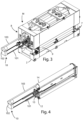
figure 1 shows an isometric view of a sanding machine according to the invention; -
figure 2 shows an isometric view of a sanding unit of the machine infigure 1 ; -
figure 3 shows an isometric view of a sanding machine according to the invention; -
figure 4 shows an isometric view of a polishing group of the machine offigure 1 ; -
figure 5 shows a side view of a machine according to the invention when the replacement assembly according to the invention is in an extracted position; -
figure 6 shows a side view of a machine according to the invention when the replacement assembly according to the invention is in a retracted position; and -
figure 7 shows a front view of auxiliary equipment for replacing an abrasive belt in a sanding machine according to the prior art. - In the various figures, similar parts will be indicated with the same reference numbers.
- The attached figures show a sanding machine M for pieces made of wood, metal, ceramic, plastic, composite materials, and the like, equipped with at least one
sanding unit 1, for smoothing said pieces, comprising anabrasive belt 11 closed in a loop, afirst operating roller 12, asecond operating roller 13, anidle roller 14, apad 15, wherein theabrasive belt 11 is arranged around thefirst operating roller 12, thesecond driving roller 13, theidle roller 14 and thepad 15. - The sanding machine M also comprises a
frame 2, a supportingcolumn 3, amotor unit 4, a transversal upright 5, acrosspiece 6, for supporting saididle roller 14, a pneumatic actuator for tensioning the abrasive belt (not shown in the figures). - In the sanding machine M there are also an
input station 7, anoutput station 8, aconveyor device 9 for transporting the pieces to be worked from saidinput station 7 to saidoutput station 8. - The
input station 7 allows the insertion of the pieces. - The
output station 8 allows the pieces to come out the pieces machined bysanding unit 1. - The
conveyor device 9, equipped with one or more motors (not shown in the figures), transports each piece to be machined from saidinput station 7 towards saidoutput station 8, in an advancement direction X. - In the embodiment described, the
conveyor device 9 comprises a plurality of transport rollers. - The
sanding unit 1 is positioned above saidconveyor device 9 and extends mainly in a Z direction, perpendicular to said X advancement direction, and in a Y direction perpendicular to said X and Z directions. - The
first operating roller 12, thesecond operating roller 13, and theidle roller 14 have a cylindrical shape and are arranged with their longitudinal axes in the Y direction. - The
sanding unit 1 is movable in the Z direction, so as to be able to carry out a sanding operation on pieces of different thicknesses. In fact, during a machining, thesanding unit 1 must be arranged at a height such that thefirst operating roller 12, thesecond operating roller 13, and thepad 15 face the piece, and the portion ofabrasive belt 11 arranged between saidfirst operating roller 12 and saidsecond operating roller 13, is in contact with a surface of the piece, placed on saidconveyor device 9. - The
sanding unit 1 performs a smoothing process on the surface of a piece when themotor unit 4 rotates thefirst operating roller 12 and thesecond operating roller 13, which transmit motion to theabrasive belt 11. - Said
first operator roller 12 andsecond operator roller 13 rotate in a discordant direction with respect to the rotation direction of the conveyor rollers of theconveyor device 9. - The supporting
column 3 is the element through which thesanding unit 1 is coupled to theframe 2 of the machine. On the supportingcolumn 3, in general, thetransversal upright 5 is installed, on which thefirst operating roller 12 and thesecond operating roller 13 are in turn installed, and themotor unit 4, having amotor 41, a pulley, not shown in the figures, and a disc brake, not shown in the figures. Thefirst operating roller 12 and thesecond operating roller 13 are driven by themotor 41, by means of a belt-type transmission. - The
transversal upright 5 is a structural element that extends horizontally above thefirst operating roller 12 and thesecond operating roller 13, and supports them by means of two vertical shoulders placed at the end of thetransversal upright 5 itself. - The pneumatic actuator, for tensioning the abrasive belt, arranged so as to have a base on the
transversal upright 5, comprises a cylinder and a piston, equipped with a stem, and supports, at the end of the stem, thecrosspiece 6, which supports theidle roller 14, whose function is to keep theabrasive belt 11 in tension. - In other embodiments, the
sanding unit 1 can comprise afirst operating roller 12 and anidle roller 14, and provide that theabrasive belt 11 is arranged, closed in a loop, around thefirst operating roller 12 and theidle roller 14. - The sanding machine M according to the invention also comprises a
replacement assembly 10 for theabrasive belt 11, coupled to saidframe 2. - The
replacement assembly 10 is equipped with guiding means 101, with asupport member 102, with a roll-upelement 103. - The
replacement assembly 10 is also arranged inside the closed loop formed by theabrasive belt 11. - The
support member 102 is coupled to the guiding means 101. - In the embodiment described, the guiding means 101 are telescopic guides.
- The roll-up
element 103 is coupled to thesupport member 102 and has one end fixed in correspondence with saididle roller 14. - The
support member 102 is able to assume a retracted position, in which said roll-upelement 103 is wound, and an extracted position, in which said roll-upelement 103 is extended. - When the roll-up
element 103 is in the extended position, it is able to support saidabrasive belt 11 when the latter is withdrawn from said first operatingroller 12 and from saididle roller 14 to be replaced. - In the embodiment described, the roll-up
element 103 is a tape that in the wound position is rolled up on itself in the form of a reel. - In the embodiment described, the roll-up
element 103 is made of polymeric fiber, preferably nylon fiber or aramid fiber. - In another embodiment, the roll-up
element 103 is equipped with an upper layer of elastomeric material or PVC, so as to increase the friction with theabrasive belt 11. - The functioning of the
replacement assembly 10 described above is as follows. - When the
abrasive belt 11 needs to be replaced because it is worn, thereplacement assembly 10 is moved in the Y direction, away from the machine, so that the roll-upelement 103 passes from the wound position to the extended position. - In this way, an operator can slide the
abrasive belt 11, to be replaced, on the roll-upelement 103 in an extended position, which acts as a support, and remove theabrasive belt 11. - Similarly, the new
abrasive belt 11 is inserted into the machine, arranging it closed in a loop around the roll-upelement 103, when this is in the extended position and subsequently making it slide in the Y direction, approaching the machine, to arrange it closed in a loop around saidfirst operating roller 12 and saididle roller 14. - Subsequently, the
replacement assembly 10 is moved in the Y direction, approaching the machine, so that the roll-upelement 103 passes from the extended position to the wound position. - In the embodiment in which the roll-up
element 103 is provided with an upper layer of elastomeric material or PVC, the roll-upelement 103 is such as to generate a friction force on theabrasive belt 11, so as to drag theabrasive belt 11 along with it, when thereplacement assembly 10 is moved in the Y direction, away from the machine and the roll-upelement 103 is brought from the wound position to the extended position. - An advantage of the present invention is that of providing an improved sanding machine equipped with an assembly for replacing the abrasive belt integrated in the machine, so as to eliminate the use of auxiliary equipment for changing the belt.
- A further advantage of the invention is that of reducing the maneuvering spaces required in the vicinity of the sanding machine.
- Another advantage of the present invention is that of reducing the risk of damaging the abrasive belt during the replacement phase of the same.
- The present invention has been described for illustrative but not limitative purposes, according to its preferred embodiments, but it is to be understood that modifications and/or changes can be introduced by those skilled in the art without departing from the relevant scope as defined in the enclosed claims.
Claims (15)
- Machine (M) for sanding pieces made of wood, metal, ceramic, plastic, composite materials, and the like, comprising:a frame (2); andat least one sanding unit (1), installed on said frame (2), comprising in turnat least a first motorized operating roller (12),an idle roller (14), andan abrasive belt (11), arranged so as to form a closed loop, around said first operating roller (12) and said idle roller (14), to sand a surface of a piece to be sanded, movable with respect to said sanding unit (1);characterized in that it comprises a replacement assembly (10), coupled to said frame (2), comprisinga support member (102), anda roll-up element (103), coupled to said support member (102),wherein said support member (102) is capable of assuming a retracted position, in which said roll-up element (103) is rolled, and an extracted position, in which said roller shutter element (103) is extended, andwherein said roll-up element (103) is capable of supporting, in said extracted position, said abrasive belt (11), when it is removed from said first operating roller (12) and from said idle roller (14).
- Sanding machine (M) according to the preceding claim, wherein said replacement assembly (10) is arranged inside said closed loop formed by said abrasive belt (11).
- Sanding machine (M) according to any one of the preceding claims, wherein said roll-up element (103) has one end fixed at said idle roller (14).
- Sanding machine (M) according to any one of the preceding claims, comprising guiding means (101), fixed to said support member (102) and to said frame (2).
- Sanding machine (M) according to the preceding claim, wherein said guiding means (101) are telescopic.
- Sanding machine (M) according to any one of the preceding claims, wherein said roll-up element (103) is a tape, which in said rolled position is rolled up on itself in the form of a reel.
- Sanding machine (M) according to any one of the preceding claims, wherein said roll-up element (103) is made of polymeric fiber.
- Sanding machine (M) according to any one of the preceding claims, wherein said roll-up element (103) has an upper layer made of elastomeric material or PVC and is able to drag with it, by friction, said abrasive belt (11) when said roll-up element (103) is made to pass from said rolled position to said extended position.
- Sanding machine (M) according to any one of the preceding claims comprisingan input station (7), for the insertion of said pieces to be machined,an output station (8), for the output of said pieces, anda conveyor device (9), to transport said workpieces from said input station (7) to said output station (8).
- Sanding machine (M) according to any one of the preceding claims,wherein said sanding unit (1) comprises a second motorized operating roller (13), andwherein said abrasive belt (11) is also arranged around said second operating roller (13).
- Sanding machine (M) according to the preceding claim, wherein said sanding assembly (1) comprises a skid (15), and wherein said abrasive belt (11) is also arranged around said skid (15).
- Replacement assembly (10), which can be installed in a sanding machine (M), of the type having a sanding unit (1) with at least one motorized first operating roller (12), an idle roller (14), an abrasive belt (11), arranged in a closed loop around said first operating roller (12) and said idle roller (14), comprising:a support member (102); anda roll-up element (103), coupled to said support member (102), having one end that can be fixed in correspondence with said idle roller (14), movable between a rolled position and an extended position;wherein said roll-up element (103) is able to support, in use, in said extended position, said abrasive belt (11) when it is removed from said first operating roller (12) and from said idle roller (14).
- Operating method of a sanding machine (M) according to any one of claims 1-11 comprising the steps of:pulling said roll-up element (103) so as to make it pass from said rolled position to said extended position;removing said abrasive belt (11) from said first operating roller (12) and from said idle roller (14) so that it is supported by said roll-up element (103); andremoving said abrasive belt (11) from said roll-up element (103).
- Operating method of a sanding machine (M) according to claims 1 and 8, comprising the steps of:pulling said roll-up element (103) so as to make it pass from said rolled position to said extended position, dragging said abrasive belt (11) with it by friction,removing said abrasive belt (11) from said roll-up element (103).
- Operating method according to any one of claims 13 or 14 further comprising the steps of:inserting an abrasive belt (11), closed in a loop around said roll-up element (103), when this is in said extended position, in such a way that said roll-up element (103) supports said abrasive belt (11);transferring said abrasive belt (11) into said sanding unit (1) so as to arrange it closed in a ring around said first operating roller (12) and said idle roller (14); andpushing said roll-up element (103) so as to make it pass from said extended position to said rolled position.
Applications Claiming Priority (1)
| Application Number | Priority Date | Filing Date | Title |
|---|---|---|---|
| IT102022000016977A IT202200016977A1 (en) | 2022-08-08 | 2022-08-08 | Perfected sanding machine |
Publications (1)
| Publication Number | Publication Date |
|---|---|
| EP4321296A1 true EP4321296A1 (en) | 2024-02-14 |
Family
ID=83900057
Family Applications (1)
| Application Number | Title | Priority Date | Filing Date |
|---|---|---|---|
| EP23189942.8A Pending EP4321296A1 (en) | 2022-08-08 | 2023-08-07 | Improved sanding machine |
Country Status (2)
| Country | Link |
|---|---|
| EP (1) | EP4321296A1 (en) |
| IT (1) | IT202200016977A1 (en) |
Citations (2)
| Publication number | Priority date | Publication date | Assignee | Title |
|---|---|---|---|---|
| ITBO940228A1 (en) * | 1994-05-18 | 1995-11-18 | Dmc Spa | DEVICE FOR THE AUTOMATIC CHANGE OF THE ABRASIVE BELT IN SANDING MACHINES, IN PARTICULAR FOR WOODEN PANELS. |
| EP2241401A1 (en) * | 2009-04-15 | 2010-10-20 | SCM Group S.p.A. | Belt sanding machine |
-
2022
- 2022-08-08 IT IT102022000016977A patent/IT202200016977A1/en unknown
-
2023
- 2023-08-07 EP EP23189942.8A patent/EP4321296A1/en active Pending
Patent Citations (2)
| Publication number | Priority date | Publication date | Assignee | Title |
|---|---|---|---|---|
| ITBO940228A1 (en) * | 1994-05-18 | 1995-11-18 | Dmc Spa | DEVICE FOR THE AUTOMATIC CHANGE OF THE ABRASIVE BELT IN SANDING MACHINES, IN PARTICULAR FOR WOODEN PANELS. |
| EP2241401A1 (en) * | 2009-04-15 | 2010-10-20 | SCM Group S.p.A. | Belt sanding machine |
Also Published As
| Publication number | Publication date |
|---|---|
| IT202200016977A1 (en) | 2024-02-08 |
Similar Documents
| Publication | Publication Date | Title |
|---|---|---|
| CN212600848U (en) | Glass double-side grinding machine | |
| CN114102886A (en) | Silicon rod processing equipment and silicon rod processing method | |
| JP4258480B2 (en) | Grinding machine and grinding system | |
| KR101870258B1 (en) | Grinding machine | |
| CN210413972U (en) | An automatic grinding device | |
| US6869349B2 (en) | Abrading machine with abrading discs, which are moved in a reciprocatory movement transverse to an item | |
| GB2144354A (en) | Grinding apparatus | |
| CN106271665A (en) | A kind of rustless steel coiled material Compositions of metal-working machines | |
| CN117066907B (en) | Automatic fixed-length cutting equipment for aluminum plates | |
| CN110026867B (en) | Multi-angle machining roller manufacturing device | |
| HU212999B (en) | Belt grinding aggregate and rail grinding machine for grinding the unevennesses of the railhead surface of one or both rails of a track | |
| EP1477275B1 (en) | Abrading machine with abrading discs, which are moved in a reciprocatory movement transverse to the item | |
| CN212044053U (en) | Roller polishing machine of textile machinery | |
| EP0575084B1 (en) | Machine for grinding a belt | |
| US4135620A (en) | Adjustable conveying device | |
| CN206764028U (en) | A kind of automatic bead string rope blade grinding machine | |
| CN109153103B (en) | with finishing equipment | |
| KR101887802B1 (en) | Automatic abrasion machine | |
| FI76272B (en) | FOERFARANDE OCH ANORDNING FOER SLIPNING AEVEN AV SMAO ARBETSSTYCKEN. | |
| CN211029447U (en) | Plane sander | |
| CN215547673U (en) | Rust removal device for pipeline machining | |
| CN118046289B (en) | Machining device for hydraulic cylinder | |
| EP4015146B1 (en) | Sander machine | |
| EP3834986B1 (en) | Sanding machine provided with an auxiliary device to facilitate mounting an abrasive belt | |
| EP2123396A1 (en) | Smoothing/brushing machine for wooden articles and relative operating method |
Legal Events
| Date | Code | Title | Description |
|---|---|---|---|
| PUAI | Public reference made under article 153(3) epc to a published international application that has entered the european phase |
Free format text: ORIGINAL CODE: 0009012 |
|
| STAA | Information on the status of an ep patent application or granted ep patent |
Free format text: STATUS: THE APPLICATION HAS BEEN PUBLISHED |
|
| AK | Designated contracting states |
Kind code of ref document: A1 Designated state(s): AL AT BE BG CH CY CZ DE DK EE ES FI FR GB GR HR HU IE IS IT LI LT LU LV MC ME MK MT NL NO PL PT RO RS SE SI SK SM TR |
|
| STAA | Information on the status of an ep patent application or granted ep patent |
Free format text: STATUS: REQUEST FOR EXAMINATION WAS MADE |
|
| 17P | Request for examination filed |
Effective date: 20240812 |
|
| RBV | Designated contracting states (corrected) |
Designated state(s): AL AT BE BG CH CY CZ DE DK EE ES FI FR GB GR HR HU IE IS IT LI LT LU LV MC ME MK MT NL NO PL PT RO RS SE SI SK SM TR |