EP4321094A2 - Blood collection adapter and related devices to reduce hemolysis - Google Patents
Blood collection adapter and related devices to reduce hemolysis Download PDFInfo
- Publication number
- EP4321094A2 EP4321094A2 EP23219962.0A EP23219962A EP4321094A2 EP 4321094 A2 EP4321094 A2 EP 4321094A2 EP 23219962 A EP23219962 A EP 23219962A EP 4321094 A2 EP4321094 A2 EP 4321094A2
- Authority
- EP
- European Patent Office
- Prior art keywords
- adapter
- connector
- groove
- blood collection
- component
- Prior art date
- Legal status (The legal status is an assumption and is not a legal conclusion. Google has not performed a legal analysis and makes no representation as to the accuracy of the status listed.)
- Granted
Links
Images


Classifications
-
- A—HUMAN NECESSITIES
- A61—MEDICAL OR VETERINARY SCIENCE; HYGIENE
- A61B—DIAGNOSIS; SURGERY; IDENTIFICATION
- A61B5/00—Measuring for diagnostic purposes; Identification of persons
- A61B5/15—Devices for taking samples of blood
- A61B5/150992—Blood sampling from a fluid line external to a patient, such as a catheter line, combined with an infusion line; Blood sampling from indwelling needle sets, e.g. sealable ports, luer couplings or valves
-
- A—HUMAN NECESSITIES
- A61—MEDICAL OR VETERINARY SCIENCE; HYGIENE
- A61B—DIAGNOSIS; SURGERY; IDENTIFICATION
- A61B5/00—Measuring for diagnostic purposes; Identification of persons
- A61B5/15—Devices for taking samples of blood
- A61B5/150007—Details
- A61B5/150015—Source of blood
- A61B5/15003—Source of blood for venous or arterial blood
-
- A—HUMAN NECESSITIES
- A61—MEDICAL OR VETERINARY SCIENCE; HYGIENE
- A61B—DIAGNOSIS; SURGERY; IDENTIFICATION
- A61B5/00—Measuring for diagnostic purposes; Identification of persons
- A61B5/15—Devices for taking samples of blood
- A61B5/153—Devices specially adapted for taking samples of venous or arterial blood, e.g. with syringes
- A61B5/154—Devices using pre-evacuated means
-
- A—HUMAN NECESSITIES
- A61—MEDICAL OR VETERINARY SCIENCE; HYGIENE
- A61B—DIAGNOSIS; SURGERY; IDENTIFICATION
- A61B5/00—Measuring for diagnostic purposes; Identification of persons
- A61B5/15—Devices for taking samples of blood
- A61B5/150007—Details
- A61B5/150206—Construction or design features not otherwise provided for; manufacturing or production; packages; sterilisation of piercing element, piercing device or sampling device
-
- A—HUMAN NECESSITIES
- A61—MEDICAL OR VETERINARY SCIENCE; HYGIENE
- A61B—DIAGNOSIS; SURGERY; IDENTIFICATION
- A61B5/00—Measuring for diagnostic purposes; Identification of persons
- A61B5/15—Devices for taking samples of blood
- A61B5/150007—Details
- A61B5/150366—Blood collection bags, e.g. connected to the patient by a catheter comprising means for removing a small sample of collected blood from the bag
-
- A—HUMAN NECESSITIES
- A61—MEDICAL OR VETERINARY SCIENCE; HYGIENE
- A61B—DIAGNOSIS; SURGERY; IDENTIFICATION
- A61B5/00—Measuring for diagnostic purposes; Identification of persons
- A61B5/15—Devices for taking samples of blood
- A61B5/150007—Details
- A61B5/150946—Means for varying, regulating, indicating or limiting the speed or time of blood collection
-
- A—HUMAN NECESSITIES
- A61—MEDICAL OR VETERINARY SCIENCE; HYGIENE
- A61B—DIAGNOSIS; SURGERY; IDENTIFICATION
- A61B5/00—Measuring for diagnostic purposes; Identification of persons
- A61B5/15—Devices for taking samples of blood
- A61B5/153—Devices specially adapted for taking samples of venous or arterial blood, e.g. with syringes
-
- A—HUMAN NECESSITIES
- A61—MEDICAL OR VETERINARY SCIENCE; HYGIENE
- A61B—DIAGNOSIS; SURGERY; IDENTIFICATION
- A61B5/00—Measuring for diagnostic purposes; Identification of persons
- A61B5/15—Devices for taking samples of blood
- A61B5/153—Devices specially adapted for taking samples of venous or arterial blood, e.g. with syringes
- A61B5/1535—Devices specially adapted for taking samples of venous or arterial blood, e.g. with syringes comprising means for indicating vein or arterial entry
-
- A—HUMAN NECESSITIES
- A61—MEDICAL OR VETERINARY SCIENCE; HYGIENE
- A61B—DIAGNOSIS; SURGERY; IDENTIFICATION
- A61B5/00—Measuring for diagnostic purposes; Identification of persons
- A61B5/15—Devices for taking samples of blood
- A61B5/153—Devices specially adapted for taking samples of venous or arterial blood, e.g. with syringes
- A61B5/154—Devices using pre-evacuated means
- A61B5/1545—Devices using pre-evacuated means comprising means for indicating vein or arterial entry
-
- A—HUMAN NECESSITIES
- A61—MEDICAL OR VETERINARY SCIENCE; HYGIENE
- A61M—DEVICES FOR INTRODUCING MEDIA INTO, OR ONTO, THE BODY; DEVICES FOR TRANSDUCING BODY MEDIA OR FOR TAKING MEDIA FROM THE BODY; DEVICES FOR PRODUCING OR ENDING SLEEP OR STUPOR
- A61M39/00—Tubes, tube connectors, tube couplings, valves, access sites or the like, specially adapted for medical use
- A61M39/10—Tube connectors; Tube couplings
-
- A—HUMAN NECESSITIES
- A61—MEDICAL OR VETERINARY SCIENCE; HYGIENE
- A61B—DIAGNOSIS; SURGERY; IDENTIFICATION
- A61B5/00—Measuring for diagnostic purposes; Identification of persons
- A61B5/15—Devices for taking samples of blood
- A61B5/150007—Details
- A61B5/150732—Needle holders, for instance for holding the needle by the hub, used for example with double-ended needle and pre-evacuated tube
-
- A—HUMAN NECESSITIES
- A61—MEDICAL OR VETERINARY SCIENCE; HYGIENE
- A61M—DEVICES FOR INTRODUCING MEDIA INTO, OR ONTO, THE BODY; DEVICES FOR TRANSDUCING BODY MEDIA OR FOR TAKING MEDIA FROM THE BODY; DEVICES FOR PRODUCING OR ENDING SLEEP OR STUPOR
- A61M39/00—Tubes, tube connectors, tube couplings, valves, access sites or the like, specially adapted for medical use
- A61M39/10—Tube connectors; Tube couplings
- A61M2039/1077—Adapters, e.g. couplings adapting a connector to one or several other connectors
Definitions
- Catheters are commonly used for a variety of infusion therapies.
- catheters may be used for infusing fluids, such as normal saline solution, various medicaments, and total parenteral nutrition, into a patient.
- catheters may also be used for withdrawing blood from the patient.
- a common type of catheter is an over-the-needle peripheral intravenous (“IV") catheter.
- IV intravenous
- the over-the-needle catheter may be mounted over an introducer needle having a sharp distal tip.
- a catheter assembly may include a catheter hub, the catheter extending distally from the catheter hub, and the introducer needle extending through the catheter.
- the catheter and the introducer needle may be assembled so that the distal tip of the introducer needle extends beyond the distal tip of the catheter with the bevel of the needle facing up away from skin of the patient.
- the catheter and introducer needle are generally inserted at a shallow angle through the skin into vasculature of the patient.
- a clinician In order to verify proper placement of the introducer needle and/or the catheter in the blood vessel, a clinician generally confirms that there is "flashback" of blood in a flashback chamber of the catheter assembly. Once placement of the needle has been confirmed, the clinician may temporarily occlude flow in the vasculature and remove the needle, leaving the catheter in place for future blood withdrawal or fluid infusion.
- a blood collection container For blood withdrawal or collecting a blood sample from a patient, a blood collection container may be used.
- the blood collection container may include a syringe.
- the blood collection container may include a test tube with a rubber stopper at one end.
- the test tube has had all or a portion of air removed from the test tube so pressure within the test tube is lower than ambient pressure.
- Such a blood collection container is often referred to as an internal vacuum or a vacuum tube.
- a commonly used blood collection container is a VACUTAINER ® blood collection tube, available from Becton Dickinson & Company.
- the blood collection container may be coupled to the catheter.
- a pressure in the vein is higher than a pressure in the blood collection container, which pushes blood into the blood collection container, thus filling the blood collection container with blood.
- a vacuum within the blood collection container decreases as the blood collection container fills, until the pressure in the blood collection container equalizes with the pressure in the vein, and the flow of blood stops.
- red blood cells are in a high shear stress state and susceptible to hemolysis due to a high initial pressure differential between the vein and the blood collection container. Hemolysis may result in rejection and discard of a blood sample.
- the high initial pressure differential can also result in catheter tip collapse, vein collapse, or other complications that prevent or restrict blood from filling the blood collection container.
- a pressure differential between the vein and the blood collection container decreases, and filling of the blood collection container with blood slows significantly.
- the adapter may include a distal end, which may be configured to couple to a catheter assembly.
- the adapter may include a proximal end, which may include a proximal connector configured to couple to a blood collection device.
- the adapter may include a fluid pathway disposed between the distal end and the proximal end, wherein the fluid pathway includes a non-linear portion.
- the non-linear portion may form a coil shape, an S-shape, or another suitable shape.
- the non-linear portion may extend through a tube.
- the adapter may include a lumen, which may extend through the distal end of the adapter and the proximal end of the adapter.
- the tube may be disposed within the lumen.
- the adapter may include a middle portion disposed between the distal end and the proximal end. In some embodiments, the middle portion may surround the tube.
- the distal connector may include a male luer threaded connector, a male luer slip connector, a blunt cannula, or another suitable connector.
- the proximal connector may include a female luer connector.
- the proximal end may be coupled to a blood collection device.
- the proximal end may be integrated with the blood collection device or monolithically formed with the blood collection device as a single unit.
- the proximal end may include the female luer connector, which may be coupled with a male luer connector of the blood collection device.
- the blood collection device may include a syringe.
- the blood collection device may include a needle configured to pierce a seal of an evacuated blood collection tube.
- the blood collection device may include a cylindrical holder, which may extend around the needle and may be configured to receive the evacuated blood collection tube.
- the adapter 10 may be configured to reduce a likelihood of hemolysis during blood collection using a vascular access device.
- the vascular access device may include a catheter assembly.
- the adapter 10 may include a distal end 12, which may include a distal connector 14 configured to couple to the catheter assembly.
- the distal connector 14 may include a male luer threaded connector, as illustrated in Figures 1A-1B , or another suitable connector.
- the catheter assembly may include a catheter hub, which may include a distal end, a proximal end, and a lumen extending through the distal end and the proximal end.
- the catheter assembly may include a catheter, which may be secured within the catheter hub and may extend distally from the distal end of the catheter hub.
- the catheter may include a peripheral intravenous catheter (PIVC), a peripherally inserted central catheter (PICC), or a midline catheter.
- PIVC peripheral intravenous catheter
- PICC peripherally inserted central catheter
- the catheter assembly may include or correspond to any suitable catheter assembly.
- the catheter assembly may be integrated and include an extension tube, which may extend from and be integrated with a side port of the catheter hub.
- an integrated catheter assembly is the BD NEXIVA TM Closed IV Catheter system, available from Becton Dickinson and Company of Franklin Lakes, New Jersey.
- a proximal end of the extension tube may be coupled to another adapter, such as, for example, a Y-adapter.
- the adapter 10 may be configured to couple to the other adapter.
- the catheter assembly may be non-integrated and may not include the extension tube.
- the adapter 10 may be configured to couple to the proximal end of the catheter hub or another suitable portion of the catheter assembly. In some embodiments, the adapter 10 may be coupled directly to the catheter adapter, eliminating the extension tube and providing a compact catheter system.
- the adapter 10 may include a proximal end 16, which may include a proximal connector 18 configured to couple to a blood collection device.
- the proximal connector 18 may include a female luer connector or another suitable connector.
- the adapter 10 may include a fluid pathway 20 disposed between the distal end 12 and the proximal end 16.
- fluid within the fluid pathway 20 may flow through the distal end 12 and/or the proximal end 16.
- the fluid within the fluid pathway 20 may flow through the proximal end 16 in response to opening of a septum 21 disposed within the proximal end 16.
- the septum 21 may open in response to coupling of the blood collection device to the proximal end 16 of the adapter 10.
- the septum 21 may include any suitable septum and may be different from the septum 21 illustrated.
- the septum 21 may include an accordion-like septum 21 that may open when compressed in a distal direction.
- the fluid pathway 20 may include a non-linear portion 22.
- Blood cells may experience shear stress as they flow through the fluid pathway 20.
- the maximum shear stress is along the wall of the blood cell, or wall shear stress. Wall shear stress on blood cells is considered a major source of mechanical damage to blood cells.
- the non-linear portion may facilitate increased flow resistance within the vascular access system to distribute the pressure differential and reduce shear stress experienced by red blood cells.
- the non-linear portion 22 may form a coil shape, an S-shape, or another suitable shape. As illustrated in Figures 1A-1B , in some embodiments, the non-linear portion 22 may include the coil shape, which may include a spiral. In some embodiments, no fluid flowing through the non-linear portion may flow in a straight line. In some embodiments, the non-linear portion 22 may increase a length of the fluid pathway 20 through the adapter 10 and thereby may increase flow resistance and decrease blood flow within the adapter 10. In these embodiments, a risk of hemolysis during blood collection may be reduced.
- a length of the fluid pathway 20 of the adapter 10 may be selected based on one or more of the following: a gauge and/or length of the catheter, a configuration of the catheter assembly configuration, or a clinical setup.
- the fluid pathway 20 may include a length L.
- the length L may extend from a distal end of the fluid pathway 20 to a proximal end of the fluid pathway 20.
- the length L may extend from a distal end 24 of the fluid pathway 20 to a proximal end 26 of the fluid pathway 20.
- the length L may extend from a distal end of a tube 28 to a proximal end of the tube 28.
- the length L may correspond to a length or an entire length of the adapter 10.
- the fluid pathway 20 may extend along the entire length of the adapter 10 from a distal-most portion of the adapter 10 to a proximal-most portion of the adapter 10.
- the fluid pathway 20 may include an inner diameter D.
- the inner diameter D may be constant along the length L.
- ⁇ P is a change in pressure gradient across the length of the fluid pathway 20
- D and L are the inner diameter and length, respectively, of the fluid pathway 20
- ⁇ is the viscosity of a fluid
- the fluid pathway 20 may have a cross section that is not circular or may have a complicated inner diameter profile.
- the G f value of the fluid pathway 20 may be selected to reduce the maximum shear stress for each catheter gauge to be the same or less than the maximum shear stress of a BD 21G VACUTAINER ® UltraTouch TM push button blood collection set (available from Becton, Dickinson & Company of Franklin Lakes, New Jersey), which was previously considered the gold standard for blood draws.
- G f may be equal to or more than 3.83E+06 (1/in 3 ) when a 18G catheter is used, which may reduce the wall sheer stress to reduce hemolysis.
- G f may be equal to or more than 3.27E+06 (1/in 3 ) when a 20G catheter is used, which may reduce the wall sheer stress to reduce hemolysis.
- G f may be equal to or more than 3.33E+06 (1/in 3 ) when a 22G catheter is used, which may reduce the wall sheer stress to reduce hemolysis. In some embodiments, G f may be equal to or more than 1.50E+07 (1/in 3 ) when a 24G catheter is used, which may reduce the wall sheer stress to reduce hemolysis. In some embodiments, Gymay include another value. In some embodiments, G f value of the fluid pathway may be selected to reduce the maximum shear stress for each catheter gauge to be the same or less than the maximum shear stress of a BD 25G VACUTAINER ® UltraTouch TM push button blood collection set (available from Becton, Dickinson & Company of Franklin Lakes, New Jersey).
- G f when a 18G catheter is used, G f may be equal to 3.83E+06 (1/in 3 ) plus or minus 10 percent, plus or minus 25 percent, plus or minus 50 percent, or plus or minus 75 percent, which may reduce the wall sheer stress to reduce hemolysis. In some embodiments, when a 20G catheter is used, Gymay be equal to 3.27E+06 (1/in 3 ) plus or minus 10 percent, plus or minus 25 percent, plus or minus 50 percent, or plus or minus 75 percent, which may reduce the wall sheer stress to reduce hemolysis.
- Gy when a 22G catheter is used, Gymay be equal to 3.33E+06 (1/in 3 ) plus or minus 10 percent, plus or minus 25 percent, plus or minus 50 percent, or plus or minus 75 percent, which may reduce the wall sheer stress to reduce hemolysis.
- G f when a 24G catheter is used, G f may be equal to 1.50E+07 (1/in 3 ) plus or minus 10 percent, plus or minus 25 percent, plus or minus 50 percent, or plus or minus 75 percent, which may reduce the wall sheer stress to reduce hemolysis.
- G f may include another value, which may be selected based on a gauge of the catheter. In some embodiments, G f values may be selected to be the same for 22G through 18G catheters.
- the non-linear portion 22 may reduce the risk of hemolysis, while at the same time facilitating a compact adapter 10.
- the non-linear portion 22 may extend through the tube 28, the groove 56 (see, for example, Figures 6A-6C ) or another suitable structure.
- a distal end of the tube 28 and/or a proximal end of the tube 28 may be secured within the adapter 10 at various suitable locations.
- the adapter 10 may include a lumen 30, which may extend through the distal end 12 of the adapter 10 and the proximal end 16 of the adapter 10.
- the tube 28 may be disposed within the lumen 30.
- the adapter 10 may include a middle portion 32 disposed between the distal end 12 and the proximal end 16. In some embodiments, the middle portion 32 may surround the tube 28.
- the adapter 10 may house the tube 28 with the only openings in the adapter 10 being at the distal end 12 and the proximal end 16.
- the proximal end 16 may be coupled to the blood collection device 34.
- the proximal end 16 may be integrated with the blood collection device 34 or monolithically formed with the blood collection device 34 as a single unit.
- the proximal end 16 may include the female luer connector, which may be coupled with a male luer connector of the blood collection device 34.
- the blood collection device 34 may include a needle assembly 36, which may include a needle 38 configured to receive a blood collection container.
- the blood collection container may include an evacuated blood collection tube.
- the blood collection container may have all or a portion of air removed so pressure within the blood collection container is lower than ambient pressure.
- the needle assembly 36 may include one or more threads, which may be configured to couple to a holder 40, which may be generally cylindrical and may be configured to hold the blood collection container.
- the holder 40 may be integrally formed with the needle assembly 36 or coupled to the needle assembly 36 via bonding or another suitable method.
- the holder 40 may surround the needle 38.
- the needle assembly 36 and the holder 40 may include or correspond to a luer lock access device, such as, for example, the VACUTAINER ® LUER-LOK TM Access Device available from Becton, Dickinson and Company of Franklin Lakes, New Jersey.
- a distal end of the needle assembly 36 may include the male luer connector compatible with the proximal connector 18.
- a proximal end of the needle 38 may be enveloped within an elastomeric sheath 42.
- the elastomeric sheath 42 may include an open distal end and a closed proximal end.
- the needle 38 in response to the blood collection container 34 pushing the elastomeric sheath 26 distally, the needle 38 may pierce the elastomeric sheath 42, and the needle 38 may insert into a cavity of the blood collection container.
- the fluid pathway of the vascular access system may include one or more of the needle assembly 36, the adapter 10, and the catheter assembly 37 (which may include an extension tube), may include an entirety of a blood collection pathway through which blood flows during blood collection.
- the system geometric factor G fs for the fluid pathway of the vascular access system can be determined in similar fashion as described earlier. In some embodiments, the system geometric factor G fs may be equal to or more than 7.34E+06 (1/in 3 ). In some embodiments, G fs may include another value. In some embodiments, the system geometric factor G fs may be 7.34E+06 (1/in 3 ) plus or minus 10 percent, plus or minus 25 percent, plus or minus 50 percent, or plus or minus 75 percent.
- G fs may include another value, which may be selected based on a gauge and/or length of the catheter.
- an inner diameter of the adapter 10 may be equal to or greater than a smallest inside diameter of a rest of the complete blood collection pathway for blood collection.
- the blood collection device 34 may include a syringe 35, which may include a depressible plunger.
- the blood collection device 34 may include the needle assembly 36, which may not include the holder 40.
- an adapter 44 is illustrated, according to some embodiments.
- the adapter 44 may be similar or identical to the adapter 10 of Figures 1A-2D in terms of one or more included features and/or operation.
- the distal connector 14 of the adapter 10 may include a blunt cannula 46 which may insert into a portion of the catheter assembly and/or one or more arms 48 that may clip onto a portion of the catheter assembly.
- an adapter 48 is illustrated, according to some embodiments.
- the adapter 48 may be similar or identical to the adapter 10 of Figures 1A-2D and/or the adapter 44 of Figures 3A-3B in terms of one or more included features and/or operation.
- the distal connector 14 of the adapter 10 may include a male luer slip connector 50.
- an adapter 52 is illustrated, according to some embodiments.
- the adapter 52 may be similar or identical in terms of one or more included features and/or operation to one or more of the following: the adapter 10 of Figures 1A-2D , the adapter 44 of Figures 3A-3B , and the adapter 48 of Figures 4A-4B .
- the non-linear portion 22 may form an S-shape 54 or another suitable shape.
- an adapter 55 is illustrated, according to some embodiments.
- the adapter 55 may be similar or identical in terms of one or more included features and/or operation to one or more of the following: the adapter 10 of Figures 1A-2D , the adapter 44 of Figures 3A-3B , the adapter 48 of Figures 4A-4B , and the adapter 52 of Figure 5 .
- the adapter 55 may be coupled to the blood collection device 34 (see, for example, Figures 2A-2D ).
- the non-linear portion 22 of the fluid pathway 20 may include a channel or a groove 56.
- the groove 56 may be disposed in an outer surface of an inner component 58, which may be coupled to an outer component 60.
- the groove 56 may include a coil or spiral shape.
- the groove 56 may be proximate an inner surface of the outer component 60, which may close the groove 56 such that fluid flowing through the groove 56 may not escape the groove 56 except at a distal end and a proximal end of the groove 56.
- contact between the inner component 58 and the outer component 60 may form a seal between the inner component 58 and the outer component 60.
- the outer surface of the inner component 58 may include a seal element 61, which may include silicon, rubber, plastic, or another suitable material.
- the seal element 61 may include a coil or spiral shape and may be offset from the groove 56 in the distal-proximal direction. In some embodiments, the seal element 61 may prevent fluid from escaping the groove 56 except at a distal end and a proximal end of the groove 56.
- an outer diameter of the inner component 58 may be approximately equal to or slightly less than an inner diameter of the outer component 60 such that the inner component 58 is fitted within the outer component 60.
- the inner surface of the outer component 60 may be generally cylindrical, and the outer surface of the inner component 58 may be generally cylindrical.
- the inner component 58 and the outer component 60 may be concentric.
- the inner component 58 and the outer component 60 may be integrally formed or monolithically formed as a single unit.
- the outer component 60 may include the distal end 12, which may include the distal connector 14 of Figures 1 , 3 , or 4 or another suitable connector.
- the inner component 58 may include the proximal end 16, which may include the proximal connector 18 such as a female luer connector or another suitable connector.
- a proximal end of the groove 56 may include a hole 62 that may fluidically connect the groove 56 to an opening 63 of the proximal end 16.
- a distal end of the groove 56 may include a hole that may fluidically connect the groove 56 to an opening 64 of the distal end 12.
Landscapes
- Health & Medical Sciences (AREA)
- Life Sciences & Earth Sciences (AREA)
- Engineering & Computer Science (AREA)
- Heart & Thoracic Surgery (AREA)
- Animal Behavior & Ethology (AREA)
- Hematology (AREA)
- Veterinary Medicine (AREA)
- Public Health (AREA)
- Biomedical Technology (AREA)
- General Health & Medical Sciences (AREA)
- Pathology (AREA)
- Surgery (AREA)
- Molecular Biology (AREA)
- Medical Informatics (AREA)
- Biophysics (AREA)
- Physics & Mathematics (AREA)
- Vascular Medicine (AREA)
- Manufacturing & Machinery (AREA)
- Pulmonology (AREA)
- Anesthesiology (AREA)
- Measurement Of The Respiration, Hearing Ability, Form, And Blood Characteristics Of Living Organisms (AREA)
- External Artificial Organs (AREA)
- Infusion, Injection, And Reservoir Apparatuses (AREA)
Abstract
Description
- Catheters are commonly used for a variety of infusion therapies. For example, catheters may be used for infusing fluids, such as normal saline solution, various medicaments, and total parenteral nutrition, into a patient. Catheters may also be used for withdrawing blood from the patient.
- A common type of catheter is an over-the-needle peripheral intravenous ("IV") catheter. As its name implies, the over-the-needle catheter may be mounted over an introducer needle having a sharp distal tip. A catheter assembly may include a catheter hub, the catheter extending distally from the catheter hub, and the introducer needle extending through the catheter. The catheter and the introducer needle may be assembled so that the distal tip of the introducer needle extends beyond the distal tip of the catheter with the bevel of the needle facing up away from skin of the patient. The catheter and introducer needle are generally inserted at a shallow angle through the skin into vasculature of the patient.
- In order to verify proper placement of the introducer needle and/or the catheter in the blood vessel, a clinician generally confirms that there is "flashback" of blood in a flashback chamber of the catheter assembly. Once placement of the needle has been confirmed, the clinician may temporarily occlude flow in the vasculature and remove the needle, leaving the catheter in place for future blood withdrawal or fluid infusion.
- For blood withdrawal or collecting a blood sample from a patient, a blood collection container may be used. The blood collection container may include a syringe. Alternatively, the blood collection container may include a test tube with a rubber stopper at one end. In some instances, the test tube has had all or a portion of air removed from the test tube so pressure within the test tube is lower than ambient pressure. Such a blood collection container is often referred to as an internal vacuum or a vacuum tube. A commonly used blood collection container is a VACUTAINER® blood collection tube, available from Becton Dickinson & Company.
- The blood collection container may be coupled to the catheter. When the blood collection container is coupled to the catheter, a pressure in the vein is higher than a pressure in the blood collection container, which pushes blood into the blood collection container, thus filling the blood collection container with blood. A vacuum within the blood collection container decreases as the blood collection container fills, until the pressure in the blood collection container equalizes with the pressure in the vein, and the flow of blood stops.
- Unfortunately, as blood is drawn into the blood collection container, red blood cells are in a high shear stress state and susceptible to hemolysis due to a high initial pressure differential between the vein and the blood collection container. Hemolysis may result in rejection and discard of a blood sample. The high initial pressure differential can also result in catheter tip collapse, vein collapse, or other complications that prevent or restrict blood from filling the blood collection container. As the blood collection container fills, a pressure differential between the vein and the blood collection container decreases, and filling of the blood collection container with blood slows significantly.
- The subject matter claimed herein is not limited to embodiments that solve any disadvantages or that operate only in environments such as those described above. Rather, this background is only provided to illustrate one example technology area where some implementations described herein may be practiced.
- The present disclosure relates generally to an adapter configured to reduce a likelihood of hemolysis during blood collection using a vascular access device, as well as related blood collection sets, systems, and methods. In some embodiments, the adapter may include a distal end, which may be configured to couple to a catheter assembly. In some embodiments, the adapter may include a proximal end, which may include a proximal connector configured to couple to a blood collection device. In some embodiments, the adapter may include a fluid pathway disposed between the distal end and the proximal end, wherein the fluid pathway includes a non-linear portion.
- In some embodiments, the non-linear portion may form a coil shape, an S-shape, or another suitable shape. In some embodiments, the non-linear portion may extend through a tube. In some embodiments, the adapter may include a lumen, which may extend through the distal end of the adapter and the proximal end of the adapter. In some embodiments, the tube may be disposed within the lumen. In some embodiments, the adapter may include a middle portion disposed between the distal end and the proximal end. In some embodiments, the middle portion may surround the tube.
- In some embodiments, the distal connector may include a male luer threaded connector, a male luer slip connector, a blunt cannula, or another suitable connector. In some embodiments, the proximal connector may include a female luer connector. In some embodiments, the proximal end may be coupled to a blood collection device. For example, the proximal end may be integrated with the blood collection device or monolithically formed with the blood collection device as a single unit. As another example, the proximal end may include the female luer connector, which may be coupled with a male luer connector of the blood collection device.
- In some embodiments, the blood collection device may include a syringe. In some embodiments, the blood collection device may include a needle configured to pierce a seal of an evacuated blood collection tube. In these and other embodiments, the blood collection device may include a cylindrical holder, which may extend around the needle and may be configured to receive the evacuated blood collection tube.
- It is to be understood that both the foregoing general description and the following detailed description are examples and explanatory and are not restrictive. It should be understood that the various embodiments are not limited to the arrangements and instrumentality shown in the drawings. It should also be understood that the embodiments may be combined, or that other embodiments may be utilized and that structural changes, unless so claimed, may be made without departing from the scope of the various embodiments of the present disclosure. The following detailed description is, therefore, not to be taken in a limiting sense.
- Example embodiments will be described and explained with additional specificity and detail through the use of the accompanying drawings in which:
-
Figure 1A is an upper perspective of an example adapter, according to some embodiments; -
Figure 1B is a cross-sectional view of the adapter ofFigure 1A , according to some embodiments; -
Figure 2A is an upper perspective view of the adapter ofFigure 1A integrated with an example blood collection device, according to some embodiments; -
Figure 2B is a cross-sectional view of the adapter ofFigure 1A integrated with the blood collection device ofFigure 2A , according to some embodiments; -
Figure 2C is an upper perspective view of the adapter ofFigure 1A integrated with another example blood collection device, according to some embodiments; -
Figure 2D is an upper perspective view of the adapter ofFigure 1A integrated with another example blood collection device, according to some embodiments; -
Figure 3A is an upper perspective view of another example adapter, according to some embodiments; -
Figure 3B is a cross-sectional view of the adapter ofFigure 3A , according to some embodiments; -
Figure 4A is an upper perspective view of another example adapter, according to some embodiments; -
Figure 4B is a cross-sectional view of the adapter ofFigure 4A , according to some embodiments; -
Figure 5 is a cross-sectional view of another example adapter, according to some embodiments; -
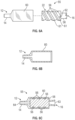
Figure 6A is an exploded view of another example adapter, according to some embodiments; -
Figure 6B is a cross-sectional view of an example outer component, according to some embodiments; and -
Figure 6C is a cross-sectional view of the adapter ofFigure 6A , according to some embodiments. - Referring now to
Figures 1A-1B , anadapter 10 is illustrated, according to some embodiments. In some embodiments, theadapter 10 may be configured to reduce a likelihood of hemolysis during blood collection using a vascular access device. In some embodiments, the vascular access device may include a catheter assembly. In some embodiments, theadapter 10 may include adistal end 12, which may include adistal connector 14 configured to couple to the catheter assembly. In some embodiments, thedistal connector 14 may include a male luer threaded connector, as illustrated inFigures 1A-1B , or another suitable connector. - In some embodiments, the catheter assembly may include a catheter hub, which may include a distal end, a proximal end, and a lumen extending through the distal end and the proximal end. In some embodiments, the catheter assembly may include a catheter, which may be secured within the catheter hub and may extend distally from the distal end of the catheter hub. In some embodiments, the catheter may include a peripheral intravenous catheter (PIVC), a peripherally inserted central catheter (PICC), or a midline catheter.
- In some embodiments, the catheter assembly may include or correspond to any suitable catheter assembly. In some embodiments, the catheter assembly may be integrated and include an extension tube, which may extend from and be integrated with a side port of the catheter hub. A non-limiting example of an integrated catheter assembly is the BD NEXIVA™ Closed IV Catheter system, available from Becton Dickinson and Company of Franklin Lakes, New Jersey. In some embodiments, a proximal end of the extension tube may be coupled to another adapter, such as, for example, a Y-adapter. In some embodiments, the
adapter 10 may be configured to couple to the other adapter. - In some embodiments, the catheter assembly may be non-integrated and may not include the extension tube. In these and other embodiments, the
adapter 10 may be configured to couple to the proximal end of the catheter hub or another suitable portion of the catheter assembly. In some embodiments, theadapter 10 may be coupled directly to the catheter adapter, eliminating the extension tube and providing a compact catheter system. - In some embodiments, the
adapter 10 may include aproximal end 16, which may include aproximal connector 18 configured to couple to a blood collection device. In some embodiments, theproximal connector 18 may include a female luer connector or another suitable connector. In some embodiments, theadapter 10 may include afluid pathway 20 disposed between thedistal end 12 and theproximal end 16. In some embodiments, fluid within thefluid pathway 20 may flow through thedistal end 12 and/or theproximal end 16. In some embodiments, the fluid within thefluid pathway 20 may flow through theproximal end 16 in response to opening of aseptum 21 disposed within theproximal end 16. In some embodiments, theseptum 21 may open in response to coupling of the blood collection device to theproximal end 16 of theadapter 10. In some embodiments, theseptum 21 may include any suitable septum and may be different from theseptum 21 illustrated. In some embodiments, theseptum 21 may include an accordion-like septum 21 that may open when compressed in a distal direction. - In some embodiments, the
fluid pathway 20 may include anon-linear portion 22. Blood cells may experience shear stress as they flow through thefluid pathway 20. The maximum shear stress is along the wall of the blood cell, or wall shear stress. Wall shear stress on blood cells is considered a major source of mechanical damage to blood cells. In some embodiments, the non-linear portion may facilitate increased flow resistance within the vascular access system to distribute the pressure differential and reduce shear stress experienced by red blood cells. - In some embodiments, the
non-linear portion 22 may form a coil shape, an S-shape, or another suitable shape. As illustrated inFigures 1A-1B , in some embodiments, thenon-linear portion 22 may include the coil shape, which may include a spiral. In some embodiments, no fluid flowing through the non-linear portion may flow in a straight line. In some embodiments, thenon-linear portion 22 may increase a length of thefluid pathway 20 through theadapter 10 and thereby may increase flow resistance and decrease blood flow within theadapter 10. In these embodiments, a risk of hemolysis during blood collection may be reduced. - In some embodiments, a length of the
fluid pathway 20 of theadapter 10 may be selected based on one or more of the following: a gauge and/or length of the catheter, a configuration of the catheter assembly configuration, or a clinical setup. In some embodiments, thefluid pathway 20 may include a length L. In some embodiments, the length L may extend from a distal end of thefluid pathway 20 to a proximal end of thefluid pathway 20. As an example, the length L may extend from adistal end 24 of thefluid pathway 20 to aproximal end 26 of thefluid pathway 20. As another example, the length L may extend from a distal end of atube 28 to a proximal end of thetube 28. In some embodiments, the length L may correspond to a length or an entire length of theadapter 10. In some embodiments, thefluid pathway 20 may extend along the entire length of theadapter 10 from a distal-most portion of theadapter 10 to a proximal-most portion of theadapter 10. In some embodiments, thefluid pathway 20 may include an inner diameter D. In some embodiments, the inner diameter D may be constant along the length L. - Fluid flow in the
fluid pathway 20, which may be tubular, can be analyzed using Poiseuille's equation:
fluid pathway 20, D and L are the inner diameter and length, respectively, of thefluid pathway 20, µ is the viscosity of a fluid, and


- In some embodiments, the
fluid pathway 20 may have multiple sections with lengths (L1, L2, L3) and inner diameters of (D1, D2, D3), the geometric factor is then:
fluid pathway 20 may have an inner diameter that changes over the length of thefluid pathway 20, the geometric factor is then:
fluid pathway 20 may have a cross section that is not circular or may have a complicated inner diameter profile. The geometric factor can then be determined by measuring the flow rate (Q) at given pressure (ΔP) with known viscosity (µ) fluid:
- The G f value of the
fluid pathway 20 may be selected to reduce the maximum shear stress for each catheter gauge to be the same or less than the maximum shear stress of a BD 21G VACUTAINER®UltraTouch™ push button blood collection set (available from Becton, Dickinson & Company of Franklin Lakes, New Jersey), which was previously considered the gold standard for blood draws. In some embodiments, G f may be equal to or more than 3.83E+06 (1/in3) when a 18G catheter is used, which may reduce the wall sheer stress to reduce hemolysis. In some embodiments, Gf may be equal to or more than 3.27E+06 (1/in3) when a 20G catheter is used, which may reduce the wall sheer stress to reduce hemolysis. In some embodiments, Gf may be equal to or more than 3.33E+06 (1/in3) when a 22G catheter is used, which may reduce the wall sheer stress to reduce hemolysis. In some embodiments, G f may be equal to or more than 1.50E+07 (1/in3) when a 24G catheter is used, which may reduce the wall sheer stress to reduce hemolysis. In some embodiments, Gymay include another value. In some embodiments, G f value of the fluid pathway may be selected to reduce the maximum shear stress for each catheter gauge to be the same or less than the maximum shear stress of a BD 25G VACUTAINER® UltraTouch™ push button blood collection set (available from Becton, Dickinson & Company of Franklin Lakes, New Jersey). - In some embodiments, when a 18G catheter is used, G f may be equal to 3.83E+06 (1/in3) plus or minus 10 percent, plus or minus 25 percent, plus or minus 50 percent, or plus or minus 75 percent, which may reduce the wall sheer stress to reduce hemolysis. In some embodiments, when a 20G catheter is used, Gymay be equal to 3.27E+06 (1/in3) plus or minus 10 percent, plus or minus 25 percent, plus or minus 50 percent, or plus or minus 75 percent, which may reduce the wall sheer stress to reduce hemolysis. In some embodiments, when a 22G catheter is used, Gymay be equal to 3.33E+06 (1/in3) plus or minus 10 percent, plus or minus 25 percent, plus or minus 50 percent, or plus or minus 75 percent, which may reduce the wall sheer stress to reduce hemolysis. In some embodiments, when a 24G catheter is used, Gf may be equal to 1.50E+07 (1/in3) plus or minus 10 percent, plus or minus 25 percent, plus or minus 50 percent, or plus or minus 75 percent, which may reduce the wall sheer stress to reduce hemolysis. In some embodiments, Gf may include another value, which may be selected based on a gauge of the catheter. In some embodiments, Gf values may be selected to be the same for 22G through 18G catheters.
- In some embodiments, the
non-linear portion 22 may reduce the risk of hemolysis, while at the same time facilitating acompact adapter 10. In some embodiments, thenon-linear portion 22 may extend through thetube 28, the groove 56 (see, for example,Figures 6A-6C ) or another suitable structure. In some embodiments, a distal end of thetube 28 and/or a proximal end of thetube 28 may be secured within theadapter 10 at various suitable locations. - In some embodiments, the
adapter 10 may include alumen 30, which may extend through thedistal end 12 of theadapter 10 and theproximal end 16 of theadapter 10. In some embodiments, thetube 28 may be disposed within thelumen 30. In some embodiments, theadapter 10 may include amiddle portion 32 disposed between thedistal end 12 and theproximal end 16. In some embodiments, themiddle portion 32 may surround thetube 28. In some embodiments, theadapter 10 may house thetube 28 with the only openings in theadapter 10 being at thedistal end 12 and theproximal end 16. - Referring now to
Figures 2A-2D , in some embodiments, theproximal end 16 may be coupled to theblood collection device 34. For example, theproximal end 16 may be integrated with theblood collection device 34 or monolithically formed with theblood collection device 34 as a single unit. As another example, theproximal end 16 may include the female luer connector, which may be coupled with a male luer connector of theblood collection device 34. - As illustrated in
Figure 2A , in some embodiments, theblood collection device 34 may include aneedle assembly 36, which may include aneedle 38 configured to receive a blood collection container. In these and other embodiments, the blood collection container may include an evacuated blood collection tube. In some embodiments, the blood collection container may have all or a portion of air removed so pressure within the blood collection container is lower than ambient pressure. - In some embodiments, the
needle assembly 36 may include one or more threads, which may be configured to couple to aholder 40, which may be generally cylindrical and may be configured to hold the blood collection container. In some embodiments, theholder 40 may be integrally formed with theneedle assembly 36 or coupled to theneedle assembly 36 via bonding or another suitable method. In some embodiments, theholder 40 may surround theneedle 38. In some embodiments, theneedle assembly 36 and theholder 40 may include or correspond to a luer lock access device, such as, for example, the VACUTAINER® LUER-LOK™ Access Device available from Becton, Dickinson and Company of Franklin Lakes, New Jersey. In some embodiments, a distal end of theneedle assembly 36 may include the male luer connector compatible with theproximal connector 18. - In some embodiments, a proximal end of the
needle 38 may be enveloped within anelastomeric sheath 42. In some embodiments, theelastomeric sheath 42 may include an open distal end and a closed proximal end. In some embodiments, in response to theblood collection container 34 pushing theelastomeric sheath 26 distally, theneedle 38 may pierce theelastomeric sheath 42, and theneedle 38 may insert into a cavity of the blood collection container. - In some embodiments, the fluid pathway of the vascular access system, which may include one or more of the
needle assembly 36, theadapter 10, and the catheter assembly 37 (which may include an extension tube), may include an entirety of a blood collection pathway through which blood flows during blood collection. The system geometric factor Gfs for the fluid pathway of the vascular access system can be determined in similar fashion as described earlier. In some embodiments, the system geometric factor Gfs may be equal to or more than 7.34E+06 (1/in3). In some embodiments, Gfs may include another value. In some embodiments, the system geometric factor Gfs may be 7.34E+06 (1/in3) plus or minus 10 percent, plus or minus 25 percent, plus or minus 50 percent, or plus or minus 75 percent. In some embodiments, Gfs may include another value, which may be selected based on a gauge and/or length of the catheter. In some embodiments, an inner diameter of theadapter 10 may be equal to or greater than a smallest inside diameter of a rest of the complete blood collection pathway for blood collection. - As illustrated in
Figure 2C , in some embodiments, theblood collection device 34 may include asyringe 35, which may include a depressible plunger. - As illustrated in
Figure 2D , in some embodiments, theblood collection device 34 may include theneedle assembly 36, which may not include theholder 40. - Referring now to
Figures 3A-3B , anadapter 44 is illustrated, according to some embodiments. In some embodiments, theadapter 44 may be similar or identical to theadapter 10 ofFigures 1A-2D in terms of one or more included features and/or operation. In some embodiments, thedistal connector 14 of theadapter 10 may include ablunt cannula 46 which may insert into a portion of the catheter assembly and/or one ormore arms 48 that may clip onto a portion of the catheter assembly. - Referring now to
Figures 4A-4B , anadapter 48 is illustrated, according to some embodiments. In some embodiments, theadapter 48 may be similar or identical to theadapter 10 ofFigures 1A-2D and/or theadapter 44 ofFigures 3A-3B in terms of one or more included features and/or operation. In some embodiments, thedistal connector 14 of theadapter 10 may include a male luer slip connector 50. - Referring now to
Figure 5 , anadapter 52 is illustrated, according to some embodiments. In some embodiments, theadapter 52 may be similar or identical in terms of one or more included features and/or operation to one or more of the following: theadapter 10 ofFigures 1A-2D , theadapter 44 ofFigures 3A-3B , and theadapter 48 ofFigures 4A-4B . In some embodiments, thenon-linear portion 22 may form an S-shape 54 or another suitable shape. - Referring now to
Figures 6A-6C , anadapter 55 is illustrated, according to some embodiments. In some embodiments, theadapter 55 may be similar or identical in terms of one or more included features and/or operation to one or more of the following: theadapter 10 ofFigures 1A-2D , theadapter 44 ofFigures 3A-3B , theadapter 48 ofFigures 4A-4B , and theadapter 52 ofFigure 5 . For example, theadapter 55 may be coupled to the blood collection device 34 (see, for example,Figures 2A-2D ). - In some embodiments, the
non-linear portion 22 of thefluid pathway 20 may include a channel or agroove 56. In some embodiments, thegroove 56 may be disposed in an outer surface of aninner component 58, which may be coupled to anouter component 60. In some embodiments, thegroove 56 may include a coil or spiral shape. In some embodiments, thegroove 56 may be proximate an inner surface of theouter component 60, which may close thegroove 56 such that fluid flowing through thegroove 56 may not escape thegroove 56 except at a distal end and a proximal end of thegroove 56. - In some embodiments, contact between the
inner component 58 and theouter component 60 may form a seal between theinner component 58 and theouter component 60. In some embodiments, the outer surface of theinner component 58 may include a seal element 61, which may include silicon, rubber, plastic, or another suitable material. In some embodiments, the seal element 61 may include a coil or spiral shape and may be offset from thegroove 56 in the distal-proximal direction. In some embodiments, the seal element 61 may prevent fluid from escaping thegroove 56 except at a distal end and a proximal end of thegroove 56. - In some embodiments, an outer diameter of the
inner component 58 may be approximately equal to or slightly less than an inner diameter of theouter component 60 such that theinner component 58 is fitted within theouter component 60. In some embodiments, the inner surface of theouter component 60 may be generally cylindrical, and the outer surface of theinner component 58 may be generally cylindrical. In some embodiments, theinner component 58 and theouter component 60 may be concentric. In some embodiments, theinner component 58 and theouter component 60 may be integrally formed or monolithically formed as a single unit. - In some embodiments, the
outer component 60 may include thedistal end 12, which may include thedistal connector 14 ofFigures 1 ,3 , or4 or another suitable connector. In some embodiments, theinner component 58 may include theproximal end 16, which may include theproximal connector 18 such as a female luer connector or another suitable connector. - In some embodiments, a proximal end of the
groove 56 may include ahole 62 that may fluidically connect thegroove 56 to anopening 63 of theproximal end 16. Similarly, in some embodiments, a distal end of thegroove 56 may include a hole that may fluidically connect thegroove 56 to anopening 64 of thedistal end 12. - All examples and conditional language recited herein are intended for pedagogical objects to aid the reader in understanding the present disclosure and the concepts contributed by the inventor to furthering the art, and are to be construed as being without limitation to such specifically recited examples and conditions. Although embodiments of the present disclosure have been described in detail, it should be understood that the various changes, substitutions, and alterations could be made hereto without departing from the spirit and scope of the present disclosure.
-
- 1. An adapter, comprising:
- a distal end, comprising a distal connector configured to couple to a catheter assembly;
- a proximal end, comprising a proximal connector configured to couple to a blood collection device; and
- a fluid pathway disposed between the distal end and the proximal end, wherein the fluid pathway includes a non-linear portion.
- 2. The adapter of Aspect 1, wherein the non-linear portion forms a coil shape.
- 3. The adapter of Aspect 1, wherein the non-linear portion forms an S-shape.
- 4. The adapter of Aspect 1, wherein the distal connector comprises a male luer threaded connector.
- 5. The adapter of Aspect 1, wherein the distal connector comprises a male luer slip connector.
- 6. The adapter of Aspect 1, wherein the distal connector comprises a blunt cannula.
- 7. The adapter of Aspect 1, wherein the proximal connector comprises a female luer connector.
- 8. The adapter of Aspect 1, wherein the non-linear portion extends through a tube.
- 9. The adapter of Aspect 8, further comprising a lumen extending through the distal end and the proximal end, wherein the tube is disposed within the lumen.
- 10. The adapter of Aspect 9, further comprising a middle portion disposed between the distal end and the proximal end, wherein the middle portion surrounds the tube.
- 11. A blood collection set, comprising:
- a blood collection device; and
- an adapter, comprising:
- a distal end, comprising a distal connector configured to couple to a catheter assembly;
- a proximal end coupled to a blood collection device; and
- a fluid pathway disposed between the distal end and the proximal end, wherein the fluid pathway includes a non-linear portion.
- 12. The adapter of Aspect 1, wherein the blood collection device comprises a syringe.
- 13. The adapter of Aspect 1, wherein the blood collection device comprises a needle configured to pierce a seal of an evacuated blood collection tube.
- 14. The adapter of Aspect 13, wherein the blood collection device further comprises a cylindrical holder extending around the needle.
- 15. The adapter of Aspect 1, wherein the non-linear portion forms a coil shape.
- 16. The adapter of Aspect 1, wherein the non-linear portion forms an S-shape.
- 17. The adapter of Aspect 1, wherein the distal connector comprises a male luer threaded connector.
- 18. The adapter of Aspect 1, wherein the distal connector comprises a male luer slip connector.
- 19. The adapter of Aspect 1, wherein the distal connector comprises a blunt cannula.
- 20. The adapter of Aspect 1, wherein the proximal end comprises a proximal connector, wherein the proximal connector comprises a female luer connector.
Claims (15)
- An adapter (55), comprising:a distal end (12), comprising a distal connector (14) configured to couple to a catheter assembly (37);a proximal end (16), comprising a proximal connector (18) configured to couple to a blood collection device (34); anda fluid pathway (20) disposed between the distal end (12) and the proximal end (16),characterized in that the fluid pathway (20) includes a non-linear portion (22) configured such that no fluid flowing through the non-linear portion (22) may flow in a straight line, with the non-linear portion (22) increasing a length of the fluid pathway (20) between the distal end (12) and the proximal end (16) as compared to a linear fluid pathway.
- The adapter (55) of claim 1, comprising:an outer component (60) comprising a cylindrical inner surface; andan inner component (58) comprising a cylindrical outer surface, the inner component (58) positioned within the outer component (60);wherein the inner component (58) comprises a groove (56) formed in the cylindrical outer surface and wherein the groove (56) is proximate the cylindrical inner surface of the outer component (60), such that the cylindrical inner surface closes the groove (56); andwherein the groove (56) and the cylindrical inner surface of the outer component (60) collectively define the fluid pathway (20).
- The adapter (55) of claim 2, wherein the outer component (60) includes the distal connector (14) thereon and the inner component (58) includes the proximal connector (18) thereon.
- The adapter (55) of claim 2 or claim 3, wherein the cylindrical outer surface of the inner component (58) includes a seal element (61), the seal element (61) comprising a coil or spiral shape that is offset from the groove (56) in a distal-proximal direction, with the seal element (61) configured to prevent fluid from escaping the groove (56) except at a distal end and a proximal end of the groove (56).
- The adapter (55) of any of claims 2-4, wherein a proximal end of the groove (56) includes a hole (62) that fluidically connects the groove (56) to an opening (63) of the proximal end (16).
- The adapter (55) of any of claims 2-5, wherein a distal end of the groove (56) includes a hole (62) that fluidically connects the groove (56) to an opening (64) of the distal end 12.
- The adapter (55) of any of claims 2-6, wherein the inner component (58) and the outer component (60) may be integrally formed or monolithically formed as a single unit
- The adapter (55) of any of claims 1-7, wherein the non-linear portion (22) forms a spiral shape.
- The adapter (55) of any of claims 1-7, wherein the non-linear portion (22) forms a coil shape.
- The adapter (55) of any of claims 1-9, wherein the distal connector (14) comprises a male luer slip connector.
- The adapter (55) of any of claims 1-10, wherein the proximal connector (18) comprises a female luer connector.
- An adapter (55), comprising:an outer component (60) comprising a cylindrical inner surface and including a distal connector (14); andan inner component (58) comprising a cylindrical outer surface and including a proximal connector (18), the inner component (58) positioned within the outer component (60);wherein the inner component (58) comprises a groove (56) formed in the cylindrical outer surface and wherein the groove (56) is proximate the cylindrical inner surface of the outer component (60), such that the cylindrical inner surface closes the groove (56); andwherein the inner component (58) and the outer component (60) define a fluid pathway (20) extending between a distal end (12) and a proximal end (16) of the adapter (55); andwherein the groove (56) and the cylindrical inner surface of the outer component (60) collectively define a non-linear portion (22) of the fluid pathway (20).
- The adapter (55) of claim 12, wherein the non-linear portion (22) forms a spiral shape.
- The adapter (55) of claim 12, wherein the non-linear portion (22) forms a coil shape.
- The adapter (55) of any of claims 12-14, wherein the distal connector (14) comprises a male luer slip connector and the proximal connector (18) comprises a female luer connector.
Applications Claiming Priority (4)
| Application Number | Priority Date | Filing Date | Title |
|---|---|---|---|
| US202062965674P | 2020-01-24 | 2020-01-24 | |
| US17/146,388 US20210228127A1 (en) | 2020-01-24 | 2021-01-11 | Blood collection adapter and related devices to reduce hemolysis |
| PCT/US2021/013108 WO2021150399A1 (en) | 2020-01-24 | 2021-01-12 | Blood collection adapter and related devices to reduce hemolysis |
| EP21704087.2A EP4093283B1 (en) | 2020-01-24 | 2021-01-12 | Blood collection adapter and related devices to reduce hemolysis |
Related Parent Applications (2)
| Application Number | Title | Priority Date | Filing Date |
|---|---|---|---|
| EP21704087.2A Division EP4093283B1 (en) | 2020-01-24 | 2021-01-12 | Blood collection adapter and related devices to reduce hemolysis |
| EP21704087.2A Division-Into EP4093283B1 (en) | 2020-01-24 | 2021-01-12 | Blood collection adapter and related devices to reduce hemolysis |
Publications (4)
| Publication Number | Publication Date |
|---|---|
| EP4321094A2 true EP4321094A2 (en) | 2024-02-14 |
| EP4321094A3 EP4321094A3 (en) | 2024-03-13 |
| EP4321094B1 EP4321094B1 (en) | 2025-02-26 |
| EP4321094C0 EP4321094C0 (en) | 2025-02-26 |
Family
ID=76969558
Family Applications (2)
| Application Number | Title | Priority Date | Filing Date |
|---|---|---|---|
| EP21704087.2A Active EP4093283B1 (en) | 2020-01-24 | 2021-01-12 | Blood collection adapter and related devices to reduce hemolysis |
| EP23219962.0A Active EP4321094B1 (en) | 2020-01-24 | 2021-01-12 | Blood collection adapter |
Family Applications Before (1)
| Application Number | Title | Priority Date | Filing Date |
|---|---|---|---|
| EP21704087.2A Active EP4093283B1 (en) | 2020-01-24 | 2021-01-12 | Blood collection adapter and related devices to reduce hemolysis |
Country Status (10)
| Country | Link |
|---|---|
| US (1) | US20210228127A1 (en) |
| EP (2) | EP4093283B1 (en) |
| JP (1) | JP7645889B2 (en) |
| KR (1) | KR20220131320A (en) |
| CN (2) | CN113243913A (en) |
| AU (1) | AU2021210835A1 (en) |
| BR (1) | BR112022014060A2 (en) |
| CA (1) | CA3164671A1 (en) |
| MX (1) | MX2022008758A (en) |
| WO (1) | WO2021150399A1 (en) |
Families Citing this family (20)
| Publication number | Priority date | Publication date | Assignee | Title |
|---|---|---|---|---|
| US20210228127A1 (en) * | 2020-01-24 | 2021-07-29 | Becton, Dickinson And Company | Blood collection adapter and related devices to reduce hemolysis |
| JP2023548656A (en) | 2020-10-08 | 2023-11-20 | ベクトン・ディキンソン・アンド・カンパニー | Intravenous catheter device with probe assembly with integrated fluid flushing mechanism |
| MX2023004163A (en) | 2020-10-12 | 2023-05-03 | Becton Dickinson Co | Blood draw syringe with hemolysis protection. |
| CA3229550A1 (en) * | 2021-09-01 | 2023-03-09 | Jon K. Burkholz | Pivc-integrated hemolysis-reduction accessories for direct blood draw |
| US12496001B2 (en) | 2021-12-23 | 2025-12-16 | Carefusion 303, Inc. | Hemolysis-reduction accessories for direct blood draw |
| JP2025501658A (en) | 2022-01-06 | 2025-01-22 | ベクトン・ディキンソン・アンド・カンパニー | Integrated catheter system having features for blood aspiration at the time of placement and allowing blood aspiration during placement - Patents.com |
| WO2023159038A1 (en) * | 2022-02-16 | 2023-08-24 | Becton, Dickinson And Company | Vascular access system with flow restriction device |
| US20230309875A1 (en) * | 2022-03-29 | 2023-10-05 | Carefusion 303, Inc. | Hemolysis-reduction connector for direct blood draw |
| WO2023192011A1 (en) * | 2022-04-01 | 2023-10-05 | Carefusion 303, Inc. | Overmolded hemolysis-reduction accessories for direct blood draw |
| EP4489834B1 (en) * | 2022-04-01 | 2025-04-23 | Carefusion 303 Inc. | Hemolysis-reduction connector for direct blood draw |
| WO2023200713A1 (en) * | 2022-04-11 | 2023-10-19 | Becton, Dickinson And Company | Blood culture sample collection device with optimized distal fluid path and pre-positioned and sterilized discard sample vacuum tube |
| US12440845B2 (en) * | 2022-04-28 | 2025-10-14 | Elizabeth Deckler | Blood collection tube |
| US20230397861A1 (en) * | 2022-06-13 | 2023-12-14 | Carefusion 303, Inc. | Pivc-integrated hemolysis-reduction accessories for direct blood draw |
| WO2024044236A1 (en) * | 2022-08-24 | 2024-02-29 | Becton, Dickinson And Company | Instrument advancement device |
| EP4577115A1 (en) * | 2022-08-24 | 2025-07-02 | Becton, Dickinson and Company | Blood culture sample collection system |
| US20240268730A1 (en) * | 2023-02-14 | 2024-08-15 | Carefusion 303. Inc. | Fluid shield devices and flow restriction devices with fluid shield devices |
| US20240325709A1 (en) * | 2023-03-28 | 2024-10-03 | Carefusion 303, Inc. | Straight canula groove hemoshield connector |
| US20240374185A1 (en) * | 2023-05-10 | 2024-11-14 | Carefusion 303, Inc. | Hemolysis-reduction connector for direct blood draw |
| US20240415432A1 (en) * | 2023-06-14 | 2024-12-19 | Becton, Dickinson And Company | Catheter system for arterial blood draw and related methods |
| US20250025676A1 (en) * | 2023-07-17 | 2025-01-23 | Carefusion 303, Inc. | Flow restriction adapter for restricting hemolysis |
Family Cites Families (21)
| Publication number | Priority date | Publication date | Assignee | Title |
|---|---|---|---|---|
| US4492634A (en) * | 1982-09-28 | 1985-01-08 | Emde Medical Research | Pre-evacuated blood collection tube with anti-hemolysis baffle system and centrifugation propelled filtration disc and efficient serum-from cells separator |
| US5178607A (en) * | 1987-07-31 | 1993-01-12 | Lynn Lawrence A | Blood aspiration assembly septum and blunt needle aspirator |
| US5873841A (en) * | 1997-02-07 | 1999-02-23 | Vascular Logics, Inc. | Syringe with decelerating device |
| KR20010049172A (en) * | 1997-04-08 | 2001-06-15 | 인젝티미드, 인코포레이티드. | Method and apparatus for collecting blood |
| US6592566B2 (en) * | 2000-02-03 | 2003-07-15 | Arizona Board Of Regents | Method for forming an endovascular occlusion |
| US20030055381A1 (en) * | 2001-09-17 | 2003-03-20 | Wilkinson Bradley M. | Medical devices |
| US7662110B2 (en) * | 2003-07-30 | 2010-02-16 | One Stick, Llc | Devices for collecting blood and administering medical fluids |
| JP2011055916A (en) * | 2009-09-07 | 2011-03-24 | Terumo Corp | Blood container for examination and blood sampling instrument |
| WO2013028759A1 (en) * | 2011-08-22 | 2013-02-28 | The General Hospital Corporation | Assessing coagulation |
| US9427707B2 (en) * | 2012-08-10 | 2016-08-30 | Jean I. Montagu | Filtering blood |
| US20150283334A1 (en) * | 2012-10-29 | 2015-10-08 | Vibrovein Pty Ltd | Method of tuning a vibrating medical device and a connector for the same |
| ES2860954T3 (en) * | 2012-11-21 | 2021-10-05 | Amgen Inc | Drug delivery device |
| CN204016307U (en) * | 2014-07-24 | 2014-12-17 | 温州市高德医疗器械有限公司 | A kind of vacuum test tube |
| US10595760B2 (en) * | 2015-05-05 | 2020-03-24 | University Of Massachusetts | Compliant syringe system, a method of making, and of using the same |
| ES2792025T3 (en) * | 2015-10-28 | 2020-11-06 | Carefusion 303 Inc | Closed IV access device with needleless port and connector |
| CN106880363A (en) * | 2015-12-16 | 2017-06-23 | 江苏康捷医疗器械有限公司 | A kind of vacuum test tube |
| US12097027B2 (en) * | 2016-11-18 | 2024-09-24 | Magnolia Medical Technologies, Inc. | Systems and methods for sample collection with reduced hemolysis |
| CN208573745U (en) * | 2018-04-03 | 2019-03-05 | 四川莱伯医疗器械有限公司 | Convenient for the vacuum blood collection tube of blood sampling |
| US10871788B2 (en) * | 2018-08-13 | 2020-12-22 | 410 Medical, Inc. | Systems, apparatus, and methods for reducing fluid pressure in a fluid line |
| US11439333B2 (en) * | 2019-01-18 | 2022-09-13 | Becton, Dickinson And Company | Blood collection system including a baffle |
| US20210228127A1 (en) * | 2020-01-24 | 2021-07-29 | Becton, Dickinson And Company | Blood collection adapter and related devices to reduce hemolysis |
-
2021
- 2021-01-11 US US17/146,388 patent/US20210228127A1/en active Pending
- 2021-01-12 EP EP21704087.2A patent/EP4093283B1/en active Active
- 2021-01-12 BR BR112022014060A patent/BR112022014060A2/en unknown
- 2021-01-12 JP JP2022545017A patent/JP7645889B2/en active Active
- 2021-01-12 AU AU2021210835A patent/AU2021210835A1/en active Pending
- 2021-01-12 CA CA3164671A patent/CA3164671A1/en active Pending
- 2021-01-12 MX MX2022008758A patent/MX2022008758A/en unknown
- 2021-01-12 EP EP23219962.0A patent/EP4321094B1/en active Active
- 2021-01-12 WO PCT/US2021/013108 patent/WO2021150399A1/en not_active Ceased
- 2021-01-12 KR KR1020227029193A patent/KR20220131320A/en active Pending
- 2021-01-22 CN CN202110086533.6A patent/CN113243913A/en active Pending
- 2021-01-22 CN CN202120186643.5U patent/CN215651145U/en active Active
Also Published As
| Publication number | Publication date |
|---|---|
| KR20220131320A (en) | 2022-09-27 |
| CA3164671A1 (en) | 2021-07-29 |
| EP4093283B1 (en) | 2024-04-03 |
| JP2023514494A (en) | 2023-04-06 |
| EP4321094B1 (en) | 2025-02-26 |
| AU2021210835A1 (en) | 2022-08-25 |
| EP4321094A3 (en) | 2024-03-13 |
| CN113243913A (en) | 2021-08-13 |
| US20210228127A1 (en) | 2021-07-29 |
| WO2021150399A1 (en) | 2021-07-29 |
| CN215651145U (en) | 2022-01-28 |
| EP4093283C0 (en) | 2024-04-03 |
| BR112022014060A2 (en) | 2022-09-13 |
| MX2022008758A (en) | 2022-07-27 |
| JP7645889B2 (en) | 2025-03-14 |
| EP4321094C0 (en) | 2025-02-26 |
| EP4093283A1 (en) | 2022-11-30 |
Similar Documents
| Publication | Publication Date | Title |
|---|---|---|
| EP4321094B1 (en) | Blood collection adapter | |
| EP4076188B1 (en) | Catheter extension set | |
| EP4196011B1 (en) | Blood collection device and related systems | |
| EP4093284B1 (en) | Catheter having dedicated blood collection port | |
| EP4225402B1 (en) | Blood draw syringe with hemolysis protection | |
| CN216366262U (en) | Catheter system | |
| US20220379104A1 (en) | Vascular Access Device Having an Instrument Configured to Insert Into a Catheter | |
| US20240416086A1 (en) | Arterial hemoshield device for arterial blood draw and related methods | |
| US20240415432A1 (en) | Catheter system for arterial blood draw and related methods |
Legal Events
| Date | Code | Title | Description |
|---|---|---|---|
| PUAI | Public reference made under article 153(3) epc to a published international application that has entered the european phase |
Free format text: ORIGINAL CODE: 0009012 |
|
| STAA | Information on the status of an ep patent application or granted ep patent |
Free format text: STATUS: THE APPLICATION HAS BEEN PUBLISHED |
|
| REG | Reference to a national code |
Ref country code: DE Ref legal event code: R079 Free format text: PREVIOUS MAIN CLASS: A61B0005153000 Ipc: A61B0005150000 Ref document number: 602021026970 Country of ref document: DE |
|
| PUAL | Search report despatched |
Free format text: ORIGINAL CODE: 0009013 |
|
| AC | Divisional application: reference to earlier application |
Ref document number: 4093283 Country of ref document: EP Kind code of ref document: P |
|
| AK | Designated contracting states |
Kind code of ref document: A2 Designated state(s): AL AT BE BG CH CY CZ DE DK EE ES FI FR GB GR HR HU IE IS IT LI LT LU LV MC MK MT NL NO PL PT RO RS SE SI SK SM TR |
|
| AK | Designated contracting states |
Kind code of ref document: A3 Designated state(s): AL AT BE BG CH CY CZ DE DK EE ES FI FR GB GR HR HU IE IS IT LI LT LU LV MC MK MT NL NO PL PT RO RS SE SI SK SM TR |
|
| RIC1 | Information provided on ipc code assigned before grant |
Ipc: A61B 5/153 20060101ALI20240207BHEP Ipc: A61B 5/154 20060101ALI20240207BHEP Ipc: A61B 5/15 20060101AFI20240207BHEP |
|
| STAA | Information on the status of an ep patent application or granted ep patent |
Free format text: STATUS: REQUEST FOR EXAMINATION WAS MADE |
|
| GRAP | Despatch of communication of intention to grant a patent |
Free format text: ORIGINAL CODE: EPIDOSNIGR1 |
|
| STAA | Information on the status of an ep patent application or granted ep patent |
Free format text: STATUS: GRANT OF PATENT IS INTENDED |
|
| 17P | Request for examination filed |
Effective date: 20240724 |
|
| RBV | Designated contracting states (corrected) |
Designated state(s): AL AT BE BG CH CY CZ DE DK EE ES FI FR GB GR HR HU IE IS IT LI LT LU LV MC MK MT NL NO PL PT RO RS SE SI SK SM TR |
|
| RIC1 | Information provided on ipc code assigned before grant |
Ipc: A61B 5/153 20060101ALI20240812BHEP Ipc: A61B 5/154 20060101ALI20240812BHEP Ipc: A61B 5/15 20060101AFI20240812BHEP |
|
| INTG | Intention to grant announced |
Effective date: 20240826 |
|
| GRAS | Grant fee paid |
Free format text: ORIGINAL CODE: EPIDOSNIGR3 |
|
| GRAA | (expected) grant |
Free format text: ORIGINAL CODE: 0009210 |
|
| STAA | Information on the status of an ep patent application or granted ep patent |
Free format text: STATUS: THE PATENT HAS BEEN GRANTED |
|
| AC | Divisional application: reference to earlier application |
Ref document number: 4093283 Country of ref document: EP Kind code of ref document: P |
|
| AK | Designated contracting states |
Kind code of ref document: B1 Designated state(s): AL AT BE BG CH CY CZ DE DK EE ES FI FR GB GR HR HU IE IS IT LI LT LU LV MC MK MT NL NO PL PT RO RS SE SI SK SM TR |
|
| REG | Reference to a national code |
Ref country code: GB Ref legal event code: FG4D |
|
| REG | Reference to a national code |
Ref country code: CH Ref legal event code: EP |
|
| REG | Reference to a national code |
Ref country code: DE Ref legal event code: R096 Ref document number: 602021026970 Country of ref document: DE |
|
| REG | Reference to a national code |
Ref country code: IE Ref legal event code: FG4D |
|
| U01 | Request for unitary effect filed |
Effective date: 20250326 |
|
| U07 | Unitary effect registered |
Designated state(s): AT BE BG DE DK EE FI FR IT LT LU LV MT NL PT RO SE SI Effective date: 20250401 |
|
| PG25 | Lapsed in a contracting state [announced via postgrant information from national office to epo] |
Ref country code: RS Free format text: LAPSE BECAUSE OF FAILURE TO SUBMIT A TRANSLATION OF THE DESCRIPTION OR TO PAY THE FEE WITHIN THE PRESCRIBED TIME-LIMIT Effective date: 20250526 |
|
| PG25 | Lapsed in a contracting state [announced via postgrant information from national office to epo] |
Ref country code: PL Free format text: LAPSE BECAUSE OF FAILURE TO SUBMIT A TRANSLATION OF THE DESCRIPTION OR TO PAY THE FEE WITHIN THE PRESCRIBED TIME-LIMIT Effective date: 20250226 |
|
| PG25 | Lapsed in a contracting state [announced via postgrant information from national office to epo] |
Ref country code: ES Free format text: LAPSE BECAUSE OF FAILURE TO SUBMIT A TRANSLATION OF THE DESCRIPTION OR TO PAY THE FEE WITHIN THE PRESCRIBED TIME-LIMIT Effective date: 20250226 |
|
| PG25 | Lapsed in a contracting state [announced via postgrant information from national office to epo] |
Ref country code: NO Free format text: LAPSE BECAUSE OF FAILURE TO SUBMIT A TRANSLATION OF THE DESCRIPTION OR TO PAY THE FEE WITHIN THE PRESCRIBED TIME-LIMIT Effective date: 20250526 Ref country code: IS Free format text: LAPSE BECAUSE OF FAILURE TO SUBMIT A TRANSLATION OF THE DESCRIPTION OR TO PAY THE FEE WITHIN THE PRESCRIBED TIME-LIMIT Effective date: 20250626 |
|
| PG25 | Lapsed in a contracting state [announced via postgrant information from national office to epo] |
Ref country code: HR Free format text: LAPSE BECAUSE OF FAILURE TO SUBMIT A TRANSLATION OF THE DESCRIPTION OR TO PAY THE FEE WITHIN THE PRESCRIBED TIME-LIMIT Effective date: 20250226 |
|
| PG25 | Lapsed in a contracting state [announced via postgrant information from national office to epo] |
Ref country code: GR Free format text: LAPSE BECAUSE OF FAILURE TO SUBMIT A TRANSLATION OF THE DESCRIPTION OR TO PAY THE FEE WITHIN THE PRESCRIBED TIME-LIMIT Effective date: 20250527 |
|
| PG25 | Lapsed in a contracting state [announced via postgrant information from national office to epo] |
Ref country code: SM Free format text: LAPSE BECAUSE OF FAILURE TO SUBMIT A TRANSLATION OF THE DESCRIPTION OR TO PAY THE FEE WITHIN THE PRESCRIBED TIME-LIMIT Effective date: 20250226 |
|
| PG25 | Lapsed in a contracting state [announced via postgrant information from national office to epo] |
Ref country code: CZ Free format text: LAPSE BECAUSE OF FAILURE TO SUBMIT A TRANSLATION OF THE DESCRIPTION OR TO PAY THE FEE WITHIN THE PRESCRIBED TIME-LIMIT Effective date: 20250226 |
|
| PG25 | Lapsed in a contracting state [announced via postgrant information from national office to epo] |
Ref country code: SK Free format text: LAPSE BECAUSE OF FAILURE TO SUBMIT A TRANSLATION OF THE DESCRIPTION OR TO PAY THE FEE WITHIN THE PRESCRIBED TIME-LIMIT Effective date: 20250226 |
|
| PLBE | No opposition filed within time limit |
Free format text: ORIGINAL CODE: 0009261 |
|
| STAA | Information on the status of an ep patent application or granted ep patent |
Free format text: STATUS: NO OPPOSITION FILED WITHIN TIME LIMIT |
|
| PGFP | Annual fee paid to national office [announced via postgrant information from national office to epo] |
Ref country code: GB Payment date: 20251220 Year of fee payment: 6 |
|
| U20 | Renewal fee for the european patent with unitary effect paid |
Year of fee payment: 6 Effective date: 20251217 |
|
| 26N | No opposition filed |
Effective date: 20251127 |