EP4321041A1 - Flavor inhaler - Google Patents
Flavor inhaler Download PDFInfo
- Publication number
- EP4321041A1 EP4321041A1 EP21935962.7A EP21935962A EP4321041A1 EP 4321041 A1 EP4321041 A1 EP 4321041A1 EP 21935962 A EP21935962 A EP 21935962A EP 4321041 A1 EP4321041 A1 EP 4321041A1
- Authority
- EP
- European Patent Office
- Prior art keywords
- housing
- magnet
- flavor inhaler
- abutment surface
- yoke
- Prior art date
- Legal status (The legal status is an assumption and is not a legal conclusion. Google has not performed a legal analysis and makes no representation as to the accuracy of the status listed.)
- Pending
Links
Images




Classifications
-
- A—HUMAN NECESSITIES
- A24—TOBACCO; CIGARS; CIGARETTES; SIMULATED SMOKING DEVICES; SMOKERS' REQUISITES
- A24F—SMOKERS' REQUISITES; MATCH BOXES; SIMULATED SMOKING DEVICES
- A24F40/00—Electrically operated smoking devices; Component parts thereof; Manufacture thereof; Maintenance or testing thereof; Charging means specially adapted therefor
- A24F40/40—Constructional details, e.g. connection of cartridges and battery parts
-
- A—HUMAN NECESSITIES
- A24—TOBACCO; CIGARS; CIGARETTES; SIMULATED SMOKING DEVICES; SMOKERS' REQUISITES
- A24F—SMOKERS' REQUISITES; MATCH BOXES; SIMULATED SMOKING DEVICES
- A24F40/00—Electrically operated smoking devices; Component parts thereof; Manufacture thereof; Maintenance or testing thereof; Charging means specially adapted therefor
- A24F40/20—Devices using solid inhalable precursors
Definitions
- the present invention relates to a flavor inhaler.
- Such a flavor inhaler includes, for example, a chamber that contains a flavor generation article, and a heater that heats the flavor generation article contained in the chamber. Further, for such a flavor inhaler, there has been known a member configured for releasable attachment to the outside of the apparatus for the purpose of, for example, protecting or customizing the apparatus (refer to PTL 1).
- the above-described member is releasably attachable to the flavor inhaler using a magnet.
- a releasably attachable member is expected to be unintentionally detached from the flavor inhaler due to a force applied from outside when a user is handling the flavor inhaler. Specifically, for example, when the user pulls out or puts the flavor inhaler from or into a bag or a pocket of clothes, the bag or clothes may get caught on the member and this member may be unintentionally detached from the flavor inhaler.
- One of objects of the present invention is to prevent or reduce detachment of a member of a flavor inhaler from the flavor inhaler.
- a flavor inhaler includes a first housing and a second housing connected to the first housing.
- the first housing includes a first abutment surface in abutment with the second housing.
- a length of the second housing in a first direction parallel with the first abutment surface is shorter than a length of an outer edge of the first abutment surface of the first housing in the first direction.
- the second housing is in abutment with the first abutment surface of the first housing, and the length of the second housing in the first direction is shorter than the length of the outer edge of the first abutment surface of the first housing in the first direction. This allows the second housing to be attached to the first housing so as not to protrude beyond the first abutment surface in the first direction, thereby being able to prevent or reduce the detachment of the second housing from the first housing due to some member getting caught thereon.
- an outer edge of the second housing in the first direction is located on an inner side with respect to the outer edge of the first abutment surface of the first housing in the first direction as viewed from a second direction perpendicular to the first abutment surface.
- the second housing does not protrude beyond the first abutment surface in the predetermined first direction parallel with the first abutment surface, and therefore the detachment of the second housing from the first housing due to some member getting caught thereon can be further prevented or reduced.
- the flavor inhaler further includes an atomization unit for a consumable.
- the first housing is configured to hold the atomization unit in a state that the second housing is not connected to the first housing.
- the detachment of the second housing from the first housing holding the atomization unit can be prevented or reduced. Further, even if the second housing is ever detached from the first housing, the detachment of the atomization unit from the first housing can be prevented or reduced.
- the outer edge of the second housing is located on the inner side with respect to the outer edge of the first abutment surface of the first housing as viewed from the second direction perpendicular to the first abutment surface.
- the second housing does not protrude beyond the first abutment surface in any direction parallel with the first abutment surface, and therefore the detachment of the second housing from the first housing due to some member getting caught thereon can be further prevented or reduced.
- the second housing includes a second abutment surface in abutment with the first abutment surface of the first housing.
- the second housing is spaced apart from the first housing except for the second abutment surface of the second housing in a state that the second housing is connected to the first housing.
- a gap can be prevented from being generated between the first abutment surface and the second abutment surface due to contact of a portion of the second housing other than the second abutment surface with the first housing.
- the first housing and the second housing can be prevented from being connected in such a manner that the first housing floats from the second housing.
- a foreign object such as dust can be prevented from entering inside the flavor inhaler via the gap between the first abutment surface and the second abutment surface.
- the flavor inhaler further includes a magnet and a magnetic member configured to be attracted to the magnet. Any one of the magnet and the magnetic member is directly or indirectly held on the first housing. The other of the magnet and the magnetic member is directly or indirectly held on the second housing. The magnet and the magnetic member are configured to maintain the state that the second housing is connected to the first housing.
- the first housing and the second housing are connected with the aid of a magnetic force, and therefore the second housing can be easily attached to and detached from the first housing.
- the magnet and the magnetic member are spaced apart from each other in the state that the second housing is connected to the first housing.
- the magnet and the attraction member maintain the state that the first housing and the second housing are connected by attracting each other without contacting each other, thereby being able to prevent or reduce the generation of a gap between the second housing and the first abutment surface of the first housing.
- the present configuration makes it difficult for heat transferred from this atomization unit to the magnet to be transmitted to the magnetic body because of the presence of air low in thermal conductivity in this gap. As a result, an increase in the temperature of the second housing can be suppressed.
- the flavor inhaler further includes a yoke surrounding the magnet.
- the magnet includes a first surface facing the magnetic member, a second surface opposite from the first surface, and a side surface connecting the first surface and the second surface.
- the yoke covers at least a part of the side surface of the magnet and the second surface of the magnet.
- the magnetic flux of the magnet can be directed toward the first surface side, i.e., the magnetic member side due to the yoke, and therefore the first housing and the second housing can be further strongly connected. Further, in a case where a magnetic sensor is provided to the flavor inhaler, the provision of the yoke can prevent or reduce the exertion of influence from the magnet on the magnetic sensor.
- the yoke includes a sidewall portion that covers a part of the side surface of the magnet. The magnet protrudes beyond the sidewall portion of the yoke toward the magnetic member.
- the yoke can be made from, for example, ferritic stainless steel.
- the magnet protrudes beyond the sidewall portion of the yoke toward the magnetic member, and therefore the sidewall portion of the yoke is prevented from being exposed by protruding beyond the magnet. This can save time and care for neatly processing the end portion of the sidewall portion of the yoke on the magnetic member side when processing the material of the yoke.
- the flavor inhaler further includes a recessed portion and a protrusion portion for positioning the first housing and the second housing relative to each other.
- the first housing includes any one of the recessed portion and the protrusion portion.
- the protrusion portion is configured to be fitted in the recessed portion.
- the flavor inhaler includes the recessed portion and the protrusion portion, and therefore the relative positions of the first housing and the second housing can be easily determined by connecting the second housing to the first housing so as to fit the protrusion portion into the recessed portion. Further, the second housing can be prevented from being positionally displaced out of alignment with the first housing in the state that the second housing is connected to the first housing.
- a flavor inhaler includes an atomization unit, a first housing containing the atomization unit, a second housing connected to the first housing, a magnet disposed in one of the first housing and the second housing, and a magnetic member disposed in the other of the first housing and the second housing.
- the magnet and the magnetic member are configured to maintain a state that the second housing is connected to the first housing.
- the magnet is spaced apart from the magnetic member in the state that the first housing is connected to the second housing.
- the first housing and the second housing are connected with the aid of a magnetic force, and therefore the second housing can be easily attached to and detached from the first housing. If the magnet and the magnetic member ever contact each other, this promotes a transfer of heat of the atomization unit contained in the first housing to the second housing via the magnet and the magnetic member.
- the magnet is spaced apart from the magnetic member, which makes it difficult for the heat of the atomization unit to be transferred to the second housing because of the presence of air between the magnet and the magnetic member. As a result, an increase in the temperature of the second housing can be suppressed.
- the flavor inhaler may include a first portion provided to the first housing and a second portion provided to the second housing and facing the first portion.
- a first distance between the magnet and the magnetic member is longer than a distance between the first portion and the second portion.
- the first portion and the second portion can face each other in a direction in which the magnet and the magnetic member face each other.
- the magnet is spaced apart from the magnetic member, which makes it difficult for the heat of the atomization unit to be transferred to the second housing. As a result, an increase in the temperature of the second housing can be suppressed. Further, when a force is applied to the outer surface of the second housing, the second housing may be deflected. With regard thereto, since the distance between the magnet and the magnetic member is longer than the distance between the first portion and the second portion, the first portion and the second portion contact each other before the magnet contact the magnetic member even when the second housing is deflected in the direction in which the magnetic member and the magnet face each other. Therefore, the magnet can be prevented from contacting the magnetic member.
- the first portion may be a first containing portion provided to the first housing
- the second portion may be a second containing portion provided to the second housing and facing the first containing portion.
- the magnet can be disposed in one of the first containing portion and the second containing portion.
- the magnetic member can be disposed in the other of the first containing portion and the second containing portion.
- the first distance between the magnet and the magnetic member is longer than a second distance between respective circumferential edge portions of the first containing portion and the second containing portion.
- the magnet is spaced apart from the magnetic member, which makes it difficult for the heat of the atomization unit to be transferred to the second housing. As a result, an increase in the temperature of the second housing can be suppressed. Further, when a force is applied to the outer surface of the second housing, the second housing may be deflected. With regard thereto, since the distance between the magnet and the magnetic member is longer than the second distance between the respective circumferential edge portions of the first containing portion and the second containing portion, the first containing portion and the second containing portion contact each other before the magnet contacts the magnetic member even when the second housing is deflected in the direction in which the magnet and the magnetic member face each other. Therefore, the magnet can be prevented from contacting the magnetic member. As a result, the transfer of the heat due to contact of the magnet with the magnetic member can be prevented.
- the flavor inhaler further includes a magnetic detection element configured to detect magnetism of the magnet, and a yoke containing the magnet and located between the magnet and the magnetic detection element.
- the yoke includes a sidewall portion surrounding the magnet.
- a third distance between the sidewall portion and the magnetic member is longer than the second distance.
- the third distance between the sidewall portion and the magnetic member can be the width of a gap in the direction in which the magnet and the magnetic member face each other.
- the use of the yoke allows a magnetic shield to be established so as to prevent the magnetism of the magnet from being detected by the magnetic detection element while increasing a force for attracting the second housing to the first housing. Further, since the third distance is longer than the second distance, the first containing portion and the second containing portion contact each other before the magnetic member contacts the yoke even when the second housing is deflected in the direction in which the magnetic member and the magnet face each other. Therefore, the magnetic member can be prevented from contacting the yoke. As a result, the heat transfer amount by which the heat generated in the atomization unit is transferred to the surface of the second housing can be reduced. As a result, the transfer of the heat due to contact of the magnetic member with the yoke can be prevented.
- Fig. 1A is a schematic front view of a flavor inhaler 100 according to the present embodiment.
- Fig. 1B is a schematic top view of the flavor inhaler 100 according to the present embodiment.
- Fig. 1C is a schematic bottom view of the flavor inhaler 100 according to the present embodiment.
- an X-Y-Z orthogonal coordinate system may be set for convenience of the description. In this coordinate system, a Z axis extends vertically upward. An X-Y plane is laid so as to cut across the flavor inhaler 100 horizontally. A Y axis is disposed so as to extend from the front side to the back side of the flavor inhaler 100.
- the Z axis can also be said to be an insertion direction of a consumable 110 contained in a chamber 50 of an atomization unit 30, which will be described below.
- the X-axis direction can also be said to be a device longitudinal direction in a plane perpendicular to the insertion direction of the consumable 110 or a direction in which a heating unit and a power source unit are lined up.
- the Y-axis direction can also be said to be a device lateral direction in the plane perpendicular to the insertion direction of the consumable.
- the flavor inhaler 100 is configured to be able to heat the consumable. More specifically, the flavor inhaler 100 is configured to, for example, generate an aerosol that contains a flavor by heating a stick-type consumable provided with a flavor source including an aerosol source.
- the flavor inhaler 100 includes an outer housing 101, a slide cover 102, and a switch unit 103.
- the outer housing 101 constitutes the outermost housing of the flavor inhaler 100, and is sized so as to be contained inside a user's hand. When the user uses the flavor inhaler 100, the user can inhale the aerosol while holding the outer housing 101 with his/her hand.
- the outer housing 101 includes an outer panel 70 (corresponding to at least a part of a member forming a second housing) and an outer case 80 (corresponding to at least a part of a member forming a first housing) so as to be divided in the Y-axis direction.
- the outer housing 101 can be constructed by connecting the outer panel 70 to the outer case 80 in the Y-axis direction.
- the outer panel 70 can be configured to be detachably attachable to the outer case 80.
- the slide cover 102 is slidably attached to the outer housing 101 so as to close a not-illustrated opening portion for inserting the consumable. More specifically, the slide cover 102 is configured movably along the outer surface of the outer housing 101 between a closing position (the position illustrated in Figs. 1A and 1B ), at which the slide cover 102 closes the not-illustrated opening portion of the outer housing 101, and an opening position, at which the slide cover 102 opens the not-illustrated opening portion. For example, the user can move the slide cover 102 to the closing position and the opening position by operating the slide cover 102 manually. Due to that, the side cover 102 can permit or restrict access of the consumable to inside the flavor inhaler 100.
- the switch unit 103 is used to switch on and off the actuation of the flavor inhaler 100.
- the user can cause power to be supplied from the not-illustrated power source to the not-illustrated heating unit and heat the consumable without burning it by operating the switch unit 103 in a state that the consumable is inserted in the flavor inhaler 100.
- the switch unit 103 may include a switch provided outside the outer housing 101 or may include a switch located inside the outer housing 101. In the case where the switch is located inside the outer housing 101, the switch is indirectly pressed by pressing of the switch unit 103 on the surface of the outer housing 101.
- the present embodiment will be described citing the example in which the switch of the switch unit 103 is located inside the outer housing 101.
- the flavor inhaler 100 may further include a not-illustrated terminal.
- the terminal can be an interface that connects the flavor inhaler 100 to, for example, an external power source.
- the power source provided to the flavor inhaler 100 is a rechargeable battery
- connecting the external power source to the terminal allows a current to be supplied from the external power source to the power source and the power source to be recharged.
- the flavor inhaler 100 may be configured in such a manner that data relating to the actuation of the flavor inhaler 100 can be transmitted to an external apparatus by connecting a data transmission cable to the terminal.
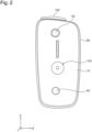
- Fig. 2 is a front view of the flavor inhaler 100 with the outer panel 70 removed therefrom.
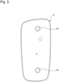
- Fig. 3 is a front view of the inner surface side of the outer panel 70.
- the flavor inhaler 100 includes an inner panel 10 (corresponding to at least a part of the member forming the first housing) inside the outer case 80.
- the inner panel 10 is contained inside the outer housing 101.
- the outer housing 101 can hold the inner panel 10 so as to prevent the inner panel 10 from being detached from the outer case 80 even in a state that the outer panel 70 is removed from the flavor inhaler 100. Therefore, the outer case 80 and the inner panel 10 can form the first housing together, which the outer panel 70 capable of forming the second housing is attached to and detached from.
- the flavor inhaler 100 includes a magnet 62 for maintaining the state that the outer panel 70 is connected to the outer case 80.
- the magnet 62 is held on the inner panel 10 held on the outer case 80.
- the magnet 62 is held indirectly on the outer case 80.
- the magnet 62 may be directly held on the outer case 80.
- the outer panel 70 may be attracted to the outer case 80 with a weak force, and may be undesirably easily disconnected.
- two or more magnets 62 are provided to the flavor inhaler 100.
- two magnets 62 are held on the inner panel 10 so as to be spaced apart in the Z direction.
- the magnets 62 may be permanent magnets or electromagnets utilizing the power source.
- the outer panel 70 includes an attraction member 64 (corresponding to one example of a magnetic member), which is attracted to the magnet 62.
- the attraction member 64 can be made from any material attracted to the magnet 62, including a magnetic material such as ferritic stainless steel or a cold-rolled steel plate. Further, the attraction member 64 may be a magnet oriented so as to be attracted to the magnet 62.
- the attraction member 64 is directly held on the outer panel 70 in the illustrated example, but is not limited thereto and may be indirectly held on the outer panel 70 via a member different from the outer panel 70.
- the attraction member 64 can be mounted on the outer panel 70 so as to face the magnet 62 when the outer panel 70 is connected to the outer case 80.
- the magnet 62 and the attraction member 64 are configured to maintain the state that the outer panel 70 is connected to the outer case 80.
- the outer panel 70 and the outer case 80 are connected with the aid of a magnetic force instead of a mechanical connection method (for example, a connection using screw fastening or an adhesive material), and therefore the outer panel 70 can be easily attached to and detached from the outer case 80 even without using a tool such as a driver or applying a strong force to release adhesion. Therefore, the flavor inhaler 100 has a structure preferable for users desiring to replace the outer panel 70 with the outer panel 70 of his/her choice.
- the magnet 62 is provided on the outer case 80 and the attraction member 64 is provided on the outer panel 70 in the example illustrated in Figs. 2 and 3 , but the magnet 62 and the attraction member 64 may be provided on the outer panel 70 and the outer case 80, respectively.
- Fig. 4 is a schematic side cross-sectional view of the consumable 110.
- a smoking system can be constituted by the flavor inhaler 100 and the consumable 110.
- the consumable 110 includes a smokable substance 111, a tubular member 114, a hollow filter unit 116, and a filter unit 115.
- the smokable substance 111 is wrapped with first rolling paper 112.
- the tubular member 114, the hollow filter unit 116, and the filter unit 115 are wrapped with second rolling paper 113 different from the first rolling paper 112.
- the second rolling paper 113 is also wrapped around a part of the first rolling paper 112 wrapped around the smokable substance 111.
- the tubular member 114, the hollow filter unit 116, and the filter unit 115, and the smokable substance 111 are joined with each other.
- the second rolling paper 113 may be omitted, and the tubular member 114, the hollow filter unit 116, and the filter unit 115, and the smokable substance 111 may be joined with each other using the first rolling paper 112.
- a lip release agent 117 which is used to make it difficult for the user's lip to stick to the second rolling paper 113, is applied to the outer surface near the end portion of the second rolling paper 113 on the filter unit 115 side.
- a portion of the consumable 110 to which the lip release agent 117 is applied functions as a mouthpiece of the consumable 110.
- an opening hole V may be concentrically provided in the circumferential direction of the tubular member 114, which fulfills a cooling segment function in the consumable 110.
- the opening hole V provided to the tubular member 114 is normally a hole for promoting an inflow of air from outside due to the user's inhalation, and the temperatures of a component and air flowing in from the smokable substance 111 can be lowered with the aid of this inflow of the air.
- the smokable substance 111 can include the flavor source such as tobacco and the aerosol source. Further, the first rolling paper 112 wrapped around the smokable substance 111 can be a breathable sheet member.
- the tubular member 114 can be a paper tube or a hollow filter.
- the consumable 110 includes the smokable substance 111, the tubular member 114, the hollow filter unit 116, and the filter unit 115 in the illustrated example, but the configuration of the consumable 110 is not limited thereto.
- the hollow filter unit 116 may be omitted, and the tubular member 114 and the filter unit 115 may be disposed adjacent to each other.
- ventilation resistance in the longitudinal direction per consumable 110 is normally 8 mmH 2 O or higher, preferably 10 mmH 2 O or higher, and further preferably 12 mmH 2 O or higher, and is normally 100 mmH 2 O or lower, preferably 80 mmH 2 O or lower, and further preferably 60 mmH 2 O or lower from a viewpoint of ease of smoking.
- Fig. 5 is a cross-sectional view of the flavor inhaler 100 as viewed from arrows 5-5 illustrated in Fig. 1B .
- the inner panel 10 is contained inside the outer housing 101 of the flavor inhaler 100.
- the inner panel 10 is made from, for example, resin, and, especially, can be made from polycarbonate (PC), ABS (Acrylonitrile-Butadiene-Styrene) resin, PEEK (polyetheretherketone), a polymer alloy containing a plurality of kinds of polymers, or the like, or metal such as aluminum.
- the inner panel 10 is preferably made from PEEK from viewpoints of thermal resistance and strength.
- the material of the inner panel 10 is not especially limited.
- the power source unit 20 and the atomization unit 30 for the consumable 110 are provided in the inner space of the inner panel 10.
- the outer housing 101 is made from, for example, resin, and, especially, can be made from polycarbonate (PC), ABS (Acrylonitrile-Butadiene-Styrene) resin, PEEK (polyetheretherketone), a polymer alloy containing a plurality of kinds of polymers, or the like, or metal such as aluminum.
- the power source unit 20 includes a power source 21.
- the power source 21 can be, for example, a rechargeable battery or a non-rechargeable battery.
- the power source 21 is electrically connected to the atomization unit 30 via a not-illustrated PCB (Printed Circuit Board) or the like. Due to that, the power source 21 can supply power to the atomization unit 30 so as to appropriately heat the consumable 110.
- PCB printed Circuit Board
- the atomization unit 30 includes the chamber 50 extending in the insertion direction of the consumable 110 (the Z-axis direction), the heating unit 40 surrounding a part of the chamber 50, a heat insulation unit 32, and a substantially tubular insertion guide member 34.
- the chamber 50 is configured to contain the consumable 110.
- the chamber 50 is preferably made from a material high in thermal resistance and low in thermal expansion coefficient, and can be made from, for example, metal such as stainless steel, resin such as PEEK, glass, or ceramic.
- a bottom member 36 may be provided on the bottom portion of the chamber 50. The bottom member 36 can function as a stopper that positions the consumable 110 inserted in the chamber 50.
- the bottom member 36 has a recess/protrusion on a surface with which the consumable 110 is in abutment, and can define a space usable to supply air to the surface with which the consumable 110 is in abutment.
- the bottom member 36 can be made from, for example, a resin material such as PEEK, metal, glass, or ceramic, but is not especially limited thereto. Further, the material for making the bottom member 36 may be a low thermally conductive member compared with the material for making the chamber 50. In a case where the bottom member 36 is joined with the bottom portion of the chamber 50, an adhesive that can be made from a resin material such as epoxy resin or an inorganic material can be used therefor.
- the heating unit 40 is configured to heat the consumable 110 contained in the chamber 50 in contact with the outer peripheral surface of the chamber 50. More specifically, the heating unit 40 includes a heating element such as a heating track and an electric insulation sheet covering at least one surface of the heating element.
- the heat insulation unit 32 is generally substantially tubular, and is disposed so as to surround the chamber 50.
- the heat insulation unit 32 can include, for example, an aerogel sheet.
- the insertion guide member 34 is made from a resin material such as PEEK, PC, or ABS, and is provided between the slide cover 102 located at the closing position and the chamber 50.
- the flavor inhaler 100 includes a first holding unit 37 and a second holding unit 38 for holding the heat insulation unit 32.
- the first holding unit 37 and the second holding unit 38 can be made from, for example, elastomer such as silicone rubber. As illustrated in Fig. 5 , the first holding unit 37 holds the end portion of the heat insulation unit 32 on the Z-axis positive direction side. Further, the second holding unit 38 holds the end portion of the heat insulation unit 32 on the Z-axis negative direction side.
- the insertion guide member 34 has a function of guiding the insertion of the consumable 110. More specifically, when the slide cover 102 is located at the opening position, the insertion guide member 34 guides insertion of the consumable 110 into the chamber 50 in reaction to insertion of the consumable 110 into the insertion guide member 34.
- the insertion guide member 34 can contact the chamber 50, and therefore the insertion guide member 34 is preferably made from PEEK from a viewpoint of thermal resistance.
- the slide cover 102 is movable between the opening position and the closing position in a direction D1.
- the flavor inhaler 100 includes a first chassis 22 extending in the Z-axis direction between the power source 21 and the atomization unit 30, and a second chassis 23 extending so as to cover the slide cover 102 side of the power source 21.
- the first chassis 22 and the second chassis 23 are configured to define a space where the power source 21 is contained in the inner panel 10.
- a printed circuit board including a control unit is contained in the flavor inhaler 100, and the power source 21, the heating unit 40, a slide cover position detection unit (not illustrated) for detecting that the slide cover 102 is moved to the opening position, a light source unit (not illustrated) that issues a notification indicating the remaining capacity of the power source 21 by lighting, the switch unit 103, and a magnetic detection element, which will be described below, are connected to this control unit.
- Fig. 6 is a cross-sectional view of the flavor inhaler 100 as viewed from arrows 6-6 illustrated in Fig. 1A .
- the outer case 80 includes a first panel portion 80a, and a first circumferential wall portion 80b, which extends from the circumferential edge of the first panel portion 80a at an angle with respect to the first panel portion 80a.
- the outer case 80 includes an opening 81, which is defined by the first circumferential wall portion 80b.
- the outer case 80 can be formed into a box-like shape having the opening 81 as a whole.
- the atomization unit 30 and the power source 21 can be contained in the outer case 80 via the opening 81 of the outer case 80.
- the inner panel 10 is configured to close the opening 81.
- the outer panel 70 is connected to the outer case 80.
- the outer panel 70 includes a second panel portion 70a, which is located opposite from the first panel portion 80a of the outer case 80, and a second circumferential wall portion 70b, which extends from the circumferential edge of the second panel portion 70a at an angle with respect to the second panel portion 70a.
- the outer panel 70 may be formed only by the second panel portion 70a. In other words, the outer panel 70 may be a substantially flat panel as a whole.
- the first chassis 22 and the inner panel 10 are fastened to each other by a screw 24.
- the head portion of the screw 24 is covered with the magnet 62.
- the flavor inhaler 100 is configured in such a manner that the screw 24 cannot be detached using a tool unless the magnet 62 is removed, thereby being configured to prohibit the user from easily disassembling the flavor inhaler 100.
- Fig. 7A is an enlarged view of a frame 7A illustrated in Fig. 6 .
- Fig. 7B is an enlarged view of a frame 7B illustrated in Fig. 6 .
- the first circumferential wall portion 80b of the outer case 80 includes a first abutment surface 82 in abutment with the outer panel 70.
- the second circumferential wall portion 70b of the outer panel 70 includes a second abutment surface 72 in abutment with the first abutment surface 82.
- abutment includes not only two members clearly in contact with each other but also two members having a slight space (for example, a space of 5 mm or smaller) therebetween due to a manufacturing error. Therefore, a slight space due to a manufacturing error may be present between the first abutment surface 82 and the second abutment surface 72.
- a member detachably attachable to the outer case 80 is expected to be unintentionally detached from the flavor inhaler 100 due to a force applied from outside when the user is handling the flavor inhaler 100.
- the length of the outer panel 70 in a first direction parallel with the first abutment surface 82 is shorter than the length of the outer edge of the first abutment surface 82 of the outer case 80 in the first direction.
- FIG. 7B is shorter than the length from a first end portion 82a of the first abutment surface 82 in the first direction illustrated in Fig. 7A to a second end portion 82b of the first abutment surface 82 in the first direction illustrated in Fig. 7B .
- This allows the outer panel 70 to be attached to the outer case 80 so as not to protrude beyond the first abutment surface 82 in the first direction as illustrated in Figs. 7A and 7B , thereby being able to prevent or reduce the detachment of the outer panel 70 from the outer case 80 due to some member getting caught thereon.
- first direction is a direction parallel with the first abutment surface 82 in the cross-section illustrated in Fig. 6
- the above-described first direction can be any direction parallel with the first abutment surface 82 without being limited to this example.
- first direction can also be said to be, for example, any direction parallel with a cross-section of the flavor inhaler 100 in which the outer panel 70 is stacked on the outer case 80.
- the outer case 80 is configured to hold the atomization unit 30 in a state that the outer panel 70 is not connected to the outer case 80.
- the outer case 80 is configured to hold the inner panel 10 therein, and therefore can hold the inner panel 10, the power source unit 20, and the atomization unit 30 even in the state that the outer panel 70 is not connected to the outer case.
- the outer edge of the outer panel 70 in the above-described first direction is located on the inner side with respect to the outer edge of the first abutment surface 82 of the outer case 80 in the above-described first direction as viewed from a second direction (the Y-axis direction) perpendicular to the first abutment surface 82.
- This allows the outer panel 70 not to protrude beyond the first abutment surface 82 in the predetermined first direction parallel with the first abutment surface 82, thereby being able to further prevent or reduce the detachment of the outer panel 70 from the outer case 80 due to some member getting caught thereon.
- the outer edge of the outer panel 70 is located on the inner side with respect to the outer edge of the first abutment surface 82 of the outer case 80 as viewed from the second direction (the Y-axis direction) perpendicular to the first abutment surface 82.
- the length of the outer panel 70 in this direction is preferably shorter than the length of the outer edge of the first abutment surface 82 of the outer case 80.
- the outer panel 70 is preferably out of contact with the outer case 80 except for the second abutment surface 72 of the outer panel 70 in the state that the outer panel 70 is connected to the outer case 80.
- This can prevent a gap from being generated between the first abutment surface 82 and the second abutment surface 72 due to contact of a portion of the outer panel 70 other than the second abutment surface 72 with the outer case 80.
- this can prevent the outer panel 70 from being connected in such a manner that the outer edge thereof floats from the outer case 80.
- a foreign object such as dust can be prevented from entering inside the flavor inhaler 100 via the gap between the first abutment surface 82 and the second abutment surface 72.
- the outer panel 70 is out of contact with the inner panel 10 in the state that the outer panel 70 is connected to the outer case 80.
- Fig. 7C is an enlarged view of a frame 7C illustrated in Fig. 6 .
- the magnet 62 can be contained in a recessed containing portion 10a formed on the inner panel 10
- the attraction member 64 can be contained in a recessed containing portion 70c formed on the outer panel 70 and fixed using an adhesive.
- the magnet 62 and the attraction member 64 are preferably spaced apart out of contact with each other in the state that the outer panel 70 is connected to the outer case 80.
- the magnet 62 and the attraction member 64 may ever contact each other, a gap may be generated between the outer panel 70 and the first abutment surface 82 of the outer case 80 depending on the manufacturing precision of the outer panel 70 and the outer case 80.
- the magnet 62 and the attraction member 64 are attracted to each other without contacting each other, thereby being able to maintain the state that the outer panel 70 and the outer case 80 are connected. Therefore, the present embodiment can prevent or reduce the generation of a gap between the outer panel 70 and the first abutment surface 82 of the outer case 80.
- a slight gap due to a manufacturing error may be generated between the first abutment surface 82 and the second abutment surface 72 as described above.
- the magnet 62 is, for example, a double-sided magnetized magnet.
- a yoke 55 is preferably used in a case where the facing surface that faces the attraction member 64 is one of the north pole and the south pole, and an opposite surface opposite from the facing surface is the other of the north pole and the south pole. In a case where one side of the magnet 62 is multipolar, the yoke 55 is unnecessary. As illustrated in Fig. 7C , the flavor inhaler 100 preferably includes the yoke 55 surrounding the magnet 62.
- the magnet 62 includes a first surface 62a, which faces the attraction member 64, a second surface 62b, which is an opposite surface from the first surface 62a, and a side surface 62c, which connects the first surface 62a and the second surface 62b.
- the yoke 55 preferably covers at least a part of the side surface 62c of the magnet 62 and the second surface 62b. This allows the magnetic flux of the magnet 62 to be directed toward the first surface 62a side, i.e., the attraction member 64 side due to the yoke 55, thereby allowing the outer panel 70 and the outer case 80 to be further strongly connected.
- a magnetic sensor (a magnetic detection element) may be provided to the flavor inhaler 100.
- the provision of the yoke 55 can make it unlikely for the magnetic sensor to be influenced by the magnet 62 (i.e., prevent the magnetic sensor from detecting magnetism of the magnet 62).
- Fig. 7D is a perspective view of the yoke 55.
- the yoke 55 includes a sidewall portion 55a, a cap portion 55b, and claw portions 55c formed on the sidewall portion 55a.
- the cap portion 55b is fixed in close contact with the second surface 62b of the magnet 62 via an adhesive.
- the sidewall portion 55a surrounds the magnet 62. More specifically, the sidewall portion 55a may cover the entire side surface 62c of the magnet 62, but preferably covers a part of the side surface 62c. Further, preferably, the magnet 62 protrudes beyond the sidewall portion 55a of the yoke 55 toward the attraction member 64 as illustrated in Fig. 7C .
- the yoke 55 can be made from, for example, a magnetic material such as ferritic stainless steel or a cold-rolled steel plate.
- the magnet 62 protrudes beyond the sidewall portion 55a of the yoke 55 toward the attraction member 64, and therefore the sidewall portion 55a of the yoke 55 is prevented from being exposed by protruding beyond the magnet 62. This can save time and care for neatly processing the end portion of the sidewall portion 55a of the yoke 55 on the attraction member 64 side when processing the material of the yoke 55.
- the north pole is placed on the first surface 62a
- the south pole is placed on the second surface 62b.
- the magnetic lines are directed from the first surface 62a to the attraction member 64, and are directed from the attraction member 64 to the distal end of the sidewall portion 55a of the yoke 55 close to the attraction member 64, thereby increasing the force attracting the attraction member 64 by the magnet 62.
- the flavor inhaler 100 is configured in such a manner that the attraction member 64 has a diameter larger than the diameter of the sidewall portion 55a to ensure this effect.
- the flavor inhaler 100 is configured in such a manner that the surface of the attraction member 64 that faces the yoke 55 has a greater width or diameter than the width or the diameter of the sidewall portion 55a of the yoke 55.
- the present embodiment allows the attraction member 64 to face the distal end of the sidewall portion 55a of the yoke 55 even with an assembling error present in the state that the outer panel 70 is connected to the outer case 80, thereby being able to avoid a reduction in the effect of attracting the attraction member 64 by the magnet 62.
- the above-described magnetic sensor can be used to detect the presence or absence of the outer panel 70. More specifically, the flavor inhaler 100 can be arranged in such a manner that the magnet 62 is provided on the inner surface of the outer panel 70, the magnetic sensor is provided on the inner panel 10 or a portion covered with the inner panel 10, and the sidewall portion 55a of the yoke 55 is located between the magnetic sensor and the magnet 62. This makes it difficult for the magnetic sensor to detect the magnetism of the magnet 62, thereby easing constraint conditions when disposing the magnetic sensor.
- the flavor inhaler 100 includes a recessed portion and a protrusion portion for positioning the outer panel 70 and the outer case 80 relative to each other. More specifically, for example, preferably, the outer panel 70 includes any one of the recessed portion and the protrusion portion, and the protrusion portion is configured to be fitted in the recessed portion.
- the outer panel 70 includes a protrusion portion 66 (or a circumferential edge portion 66), which defines the containing portion 70c of the attraction member 64. The protrusion portion 66 protrudes in a direction substantially perpendicular to the first abutment surface 82.
- the inner panel 10 includes a recessed portion 68, in which the protrusion portion 66 is fitted.
- the relative positions of the outer panel 70 and the outer case 80 can be easily determined by connecting the outer panel 70 to the outer case 80 so as to fit the protrusion portion 66 into the recessed portion 68.
- the outer panel 70 can be prevented from being positionally displaced out of alignment with the outer case 80 in the state that the outer panel 70 is connected to the outer case 80. In other words, the outer panel 70 can be restricted from being moved in parallel with the first abutment surface 82 relative to the outer case 80.
- the outer panel 70 includes the protrusion portion 66 in the present embodiment, but may include a recessed portion for fitting a protrusion portion provided on the inner panel 10 in addition thereto or instead thereof.
- the plurality of claw portions 55c is provided on the sidewall portion 55a of the yoke 55.
- the plurality of claw portions 55c is formed on the outer side with respect to the containing portion 10a, and the outer diameter of the sidewall portion 55a of the yoke 55 defined by these claw portions 55c is larger than the diameter (the inner diameter) of the containing portion 10a. Therefore, the claw portions 55c are press-fitted in the containing portion 10a when the yoke 55 is inserted into the containing portion 10a with the cap portion 55b placed to face the containing portion 10a. As a result, the yoke 55 is held so as not to be extracted from the containing portion 10a.
- the cap portion 55b and a bottom surface 10b of the containing portion 10a can be fixed using an adhesive so as to prevent the yoke 55 from being extracted from the containing portion 10a.
- L1 represents the distance from the exposed first surface 62a of the magnet 62 to the exposed surface 64a of the attraction member 64 (i.e., the surface 64a that faces the magnet 62)
- L2 represents the distance from the surface 64a of the attraction member 64 to the sidewall portion 55a of the yoke 55
- L3 and L4 represent the distances from the circumferential edge portion 66 of the containing portion 70c of the outer panel 70 to the circumferential edge portion 10c of the containing portion 10a of the inner panel 10.
- the flavor inhaler 100 is arranged in such a manner that any shorter one of L1 and L2 is longer than any shorter one of L3 and L4 in the present embodiment.
- the outer panel 70 is unintentionally deflected in a direction for reducing L1, L2, L3, and L4.
- the containing portion 70c of the outer panel 70 abuts against the circumferential edge portion 10c of the containing portion 10a of the inner panel 10 before the magnet 62 abuts against the attraction member 64 or the yoke 55 because the flavor inhaler 100 is arranged in such a manner that any shorter one of L3 and L4 (L3 because of L3 ⁇ L4 in the present embodiment) is shorter than any shorter one of L1 and L2 (L1 in the present embodiment). Therefore, the flavor inhaler 100 is configured in such a manner that the attraction member 64 abuts against neither the magnet 62 nor the yoke 55.
- the flavor inhaler 100 is not limited thereto, and the distance between the outer panel 70 and the inner panel 10 at any location may be shorter than the distance L1 or L2 between the magnet 62 and the attraction member 64 or the yoke 55. Due to that, the magnet 62 can be prevented from contacting the attraction member 64 or the yoke 55 because the outer panel 70 and the inner panel 10 contact each other before the magnet 62 contacts the attraction member 64 or the yoke 55 even when the outer panel 70 is deflected.
- the atomization unit 30 includes the heating unit 40, and therefore the heat of the atomization unit 30 can be transferred to the magnet 62. After that, the heat transferred to the magnet 62 is transmitted to the outer panel 70.
- the yoke 55 and the magnet 62 are made from metal higher in thermal conductivity compared with a resin member. Therefore, if the yoke 55 or the magnet 62 is inadvertently brought into close contact or contact with the attraction member 64, the temperature of the attraction member 64 also made from metal is raised in a short time and the heat can be transferred from the attraction member 64 to the outer panel 70.
- the outer panel 70 is held by the user, and therefore it is desirable that the temperature thereof increases as little as possible.
- the magnet 62 is spaced apart from the attraction member 64, and therefore the heat from the magnet 62 is transferred to the attraction member 64 via air (a space).
- the present embodiment can make it difficult to transfer the heat to the outer panel 70 compared with a configuration in which the magnet 62 is in contact with the attraction member 64.
- the present embodiment is arranged in such a manner that any shorter one of L3 and L4 (L3 in the present embodiment) is shorter than any shorter one of L1 and L2 (L1 in the present embodiment), thereby being able to make it difficult to increase the temperature of the outer panel 70 because the heat is transferred from the magnet 62 to the attraction member 64 via the space (the air) even when a force is applied from the outer surface of the outer panel 70.
- the flavor inhaler 100 has been described as being structured in such a manner that no member is interposed between the magnetic member 64 and the magnet 62 as described above, but, for example, a foamed member having a closed cell layer, an open cell layer, or a semi-open cell layer, such as a silicone sponge or a urethane sponge, may be disposed between magnetic member 64 and the magnet 62 because being low in thermal conductivity. This can further ensure that the abutment between the magnetic member 64 and the magnet 62 is avoided because the foamed member never has zero thickness even when any force is applied thereto from outside.
- the foamed member is provided so as to be absent at portions labeled L3 and L4 illustrated in Fig. 7C and is shaped so as to be present only between the magnetic member 64 and the magnet 62.
- the heating unit 40 is not limited to the resistively heating-type heating unit and may be an inductively heating-type heating unit.
- the heating unit 40 can heat the chamber 50 by induction heating.
- the heating unit 40 can heat the susceptor of the consumable 110 by induction heating.
- the heating unit 40 may include an internally heating-type heater that heats the consumable 110 from inside.
- the consumable 110 may be a tank that contains liquid. In this case, the heating unit 40 can be configured to atomize the liquid in the tank.
Landscapes
- Disinfection, Sterilisation Or Deodorisation Of Air (AREA)
- Catching Or Destruction (AREA)
- Packages (AREA)
Abstract
Description
- The present invention relates to a flavor inhaler.
- Conventionally, there have been known flavor inhalers for inhaling a flavor or the like without burning a material. Such a flavor inhaler includes, for example, a chamber that contains a flavor generation article, and a heater that heats the flavor generation article contained in the chamber. Further, for such a flavor inhaler, there has been known a member configured for releasable attachment to the outside of the apparatus for the purpose of, for example, protecting or customizing the apparatus (refer to PTL 1).
- PTL 1: International Publication No.
2019-084161 - In PTL 1, the above-described member is releasably attachable to the flavor inhaler using a magnet. Such a releasably attachable member is expected to be unintentionally detached from the flavor inhaler due to a force applied from outside when a user is handling the flavor inhaler. Specifically, for example, when the user pulls out or puts the flavor inhaler from or into a bag or a pocket of clothes, the bag or clothes may get caught on the member and this member may be unintentionally detached from the flavor inhaler.
- One of objects of the present invention is to prevent or reduce detachment of a member of a flavor inhaler from the flavor inhaler.
- According to a first aspect, a flavor inhaler is provided. This flavor inhaler includes a first housing and a second housing connected to the first housing. The first housing includes a first abutment surface in abutment with the second housing. A length of the second housing in a first direction parallel with the first abutment surface is shorter than a length of an outer edge of the first abutment surface of the first housing in the first direction.
- According to the first aspect, the second housing is in abutment with the first abutment surface of the first housing, and the length of the second housing in the first direction is shorter than the length of the outer edge of the first abutment surface of the first housing in the first direction. This allows the second housing to be attached to the first housing so as not to protrude beyond the first abutment surface in the first direction, thereby being able to prevent or reduce the detachment of the second housing from the first housing due to some member getting caught thereon.
- According to a second aspect, in the first aspect, an outer edge of the second housing in the first direction is located on an inner side with respect to the outer edge of the first abutment surface of the first housing in the first direction as viewed from a second direction perpendicular to the first abutment surface.
- According to the second aspect, the second housing does not protrude beyond the first abutment surface in the predetermined first direction parallel with the first abutment surface, and therefore the detachment of the second housing from the first housing due to some member getting caught thereon can be further prevented or reduced.
- According to a third aspect, in the first or second aspect, the flavor inhaler further includes an atomization unit for a consumable. The first housing is configured to hold the atomization unit in a state that the second housing is not connected to the first housing.
- According to the third aspect, the detachment of the second housing from the first housing holding the atomization unit can be prevented or reduced. Further, even if the second housing is ever detached from the first housing, the detachment of the atomization unit from the first housing can be prevented or reduced.
- According to a fourth aspect, in any of the first to third aspects, the outer edge of the second housing is located on the inner side with respect to the outer edge of the first abutment surface of the first housing as viewed from the second direction perpendicular to the first abutment surface.
- According to the fourth aspect, the second housing does not protrude beyond the first abutment surface in any direction parallel with the first abutment surface, and therefore the detachment of the second housing from the first housing due to some member getting caught thereon can be further prevented or reduced.
- According to a fifth aspect, in any of the first to fourth aspects, the second housing includes a second abutment surface in abutment with the first abutment surface of the first housing. The second housing is spaced apart from the first housing except for the second abutment surface of the second housing in a state that the second housing is connected to the first housing.
- According to the fifth aspect, a gap can be prevented from being generated between the first abutment surface and the second abutment surface due to contact of a portion of the second housing other than the second abutment surface with the first housing. In other words, the first housing and the second housing can be prevented from being connected in such a manner that the first housing floats from the second housing. As a result, a foreign object such as dust can be prevented from entering inside the flavor inhaler via the gap between the first abutment surface and the second abutment surface.
- According to a sixth aspect, in any of the first to fifth aspects, the flavor inhaler further includes a magnet and a magnetic member configured to be attracted to the magnet. Any one of the magnet and the magnetic member is directly or indirectly held on the first housing. The other of the magnet and the magnetic member is directly or indirectly held on the second housing. The magnet and the magnetic member are configured to maintain the state that the second housing is connected to the first housing.
- According to the sixth aspect, the first housing and the second housing are connected with the aid of a magnetic force, and therefore the second housing can be easily attached to and detached from the first housing.
- According to a seventh aspect, in the sixth aspect, the magnet and the magnetic member are spaced apart from each other in the state that the second housing is connected to the first housing.
- If the magnet and the attraction member ever contact each other, a gap may be generated between the second housing and the first abutment surface of the first housing depending on the design precision of the first housing and the second housing. According to the seventh aspect, the magnet and the attraction member maintain the state that the first housing and the second housing are connected by attracting each other without contacting each other, thereby being able to prevent or reduce the generation of a gap between the second housing and the first abutment surface of the first housing. Further, for example, in the case where the flavor inhaler includes the atomization unit, the present configuration makes it difficult for heat transferred from this atomization unit to the magnet to be transmitted to the magnetic body because of the presence of air low in thermal conductivity in this gap. As a result, an increase in the temperature of the second housing can be suppressed.
- According to an eighth aspect, in the sixth or seventh aspect, the flavor inhaler further includes a yoke surrounding the magnet. The magnet includes a first surface facing the magnetic member, a second surface opposite from the first surface, and a side surface connecting the first surface and the second surface. The yoke covers at least a part of the side surface of the magnet and the second surface of the magnet.
- According to the eighth aspect, the magnetic flux of the magnet can be directed toward the first surface side, i.e., the magnetic member side due to the yoke, and therefore the first housing and the second housing can be further strongly connected. Further, in a case where a magnetic sensor is provided to the flavor inhaler, the provision of the yoke can prevent or reduce the exertion of influence from the magnet on the magnetic sensor.
- According to a ninth aspect, in the eighth aspect, the yoke includes a sidewall portion that covers a part of the side surface of the magnet. The magnet protrudes beyond the sidewall portion of the yoke toward the magnetic member.
- The yoke can be made from, for example, ferritic stainless steel. According to the ninth aspect, the magnet protrudes beyond the sidewall portion of the yoke toward the magnetic member, and therefore the sidewall portion of the yoke is prevented from being exposed by protruding beyond the magnet. This can save time and care for neatly processing the end portion of the sidewall portion of the yoke on the magnetic member side when processing the material of the yoke.
- According to a tenth aspect, in any of the first to ninth aspects, the flavor inhaler further includes a recessed portion and a protrusion portion for positioning the first housing and the second housing relative to each other. The first housing includes any one of the recessed portion and the protrusion portion. The protrusion portion is configured to be fitted in the recessed portion.
- According to the tenth aspect, the flavor inhaler includes the recessed portion and the protrusion portion, and therefore the relative positions of the first housing and the second housing can be easily determined by connecting the second housing to the first housing so as to fit the protrusion portion into the recessed portion. Further, the second housing can be prevented from being positionally displaced out of alignment with the first housing in the state that the second housing is connected to the first housing.
- According to an eleventh aspect, a flavor inhaler is provided. This flavor inhaler includes an atomization unit, a first housing containing the atomization unit, a second housing connected to the first housing, a magnet disposed in one of the first housing and the second housing, and a magnetic member disposed in the other of the first housing and the second housing. The magnet and the magnetic member are configured to maintain a state that the second housing is connected to the first housing. The magnet is spaced apart from the magnetic member in the state that the first housing is connected to the second housing.
- According to the eleventh aspect, the first housing and the second housing are connected with the aid of a magnetic force, and therefore the second housing can be easily attached to and detached from the first housing. If the magnet and the magnetic member ever contact each other, this promotes a transfer of heat of the atomization unit contained in the first housing to the second housing via the magnet and the magnetic member. According to the eleventh aspect, the magnet is spaced apart from the magnetic member, which makes it difficult for the heat of the atomization unit to be transferred to the second housing because of the presence of air between the magnet and the magnetic member. As a result, an increase in the temperature of the second housing can be suppressed.
- According to a twelfth aspect, in the eleventh aspect, the flavor inhaler may include a first portion provided to the first housing and a second portion provided to the second housing and facing the first portion. Preferably, a first distance between the magnet and the magnetic member is longer than a distance between the first portion and the second portion. The first portion and the second portion can face each other in a direction in which the magnet and the magnetic member face each other.
- According to the twelfth aspect, the magnet is spaced apart from the magnetic member, which makes it difficult for the heat of the atomization unit to be transferred to the second housing. As a result, an increase in the temperature of the second housing can be suppressed. Further, when a force is applied to the outer surface of the second housing, the second housing may be deflected. With regard thereto, since the distance between the magnet and the magnetic member is longer than the distance between the first portion and the second portion, the first portion and the second portion contact each other before the magnet contact the magnetic member even when the second housing is deflected in the direction in which the magnetic member and the magnet face each other. Therefore, the magnet can be prevented from contacting the magnetic member.
- According to a thirteenth aspect, the first portion may be a first containing portion provided to the first housing, and the second portion may be a second containing portion provided to the second housing and facing the first containing portion. The magnet can be disposed in one of the first containing portion and the second containing portion. The magnetic member can be disposed in the other of the first containing portion and the second containing portion. Preferably, the first distance between the magnet and the magnetic member is longer than a second distance between respective circumferential edge portions of the first containing portion and the second containing portion.
- According to the thirteenth aspect, the magnet is spaced apart from the magnetic member, which makes it difficult for the heat of the atomization unit to be transferred to the second housing. As a result, an increase in the temperature of the second housing can be suppressed. Further, when a force is applied to the outer surface of the second housing, the second housing may be deflected. With regard thereto, since the distance between the magnet and the magnetic member is longer than the second distance between the respective circumferential edge portions of the first containing portion and the second containing portion, the first containing portion and the second containing portion contact each other before the magnet contacts the magnetic member even when the second housing is deflected in the direction in which the magnet and the magnetic member face each other. Therefore, the magnet can be prevented from contacting the magnetic member. As a result, the transfer of the heat due to contact of the magnet with the magnetic member can be prevented.
- According to a fourteenth aspect, in any of the eleventh to thirteenth aspects, the flavor inhaler further includes a magnetic detection element configured to detect magnetism of the magnet, and a yoke containing the magnet and located between the magnet and the magnetic detection element. The yoke includes a sidewall portion surrounding the magnet. A third distance between the sidewall portion and the magnetic member is longer than the second distance. The third distance between the sidewall portion and the magnetic member can be the width of a gap in the direction in which the magnet and the magnetic member face each other.
- According to the fourteenth aspect, the use of the yoke allows a magnetic shield to be established so as to prevent the magnetism of the magnet from being detected by the magnetic detection element while increasing a force for attracting the second housing to the first housing. Further, since the third distance is longer than the second distance, the first containing portion and the second containing portion contact each other before the magnetic member contacts the yoke even when the second housing is deflected in the direction in which the magnetic member and the magnet face each other. Therefore, the magnetic member can be prevented from contacting the yoke. As a result, the heat transfer amount by which the heat generated in the atomization unit is transferred to the surface of the second housing can be reduced. As a result, the transfer of the heat due to contact of the magnetic member with the yoke can be prevented.
-
-
Fig. 1A is a schematic front view of a flavor inhaler according to an embodiment of the present invention. -
Fig. 1B is a schematic top view of the flavor inhaler according to the present embodiment. -
Fig. 1C is a schematic bottom view of the flavor inhaler according to the present embodiment. -
Fig. 2 is a front view of the flavor inhaler with an outer panel removed therefrom. -
Fig. 3 is a front view of the inner surface side of the outer panel. -
Fig. 4 is a schematic side cross-sectional view of a consumable. -
Fig. 5 is a cross-sectional view of the flavor inhaler as viewed fromarrows Fig. 1B . -
Fig. 6 is a cross-sectional view of the flavor inhaler as viewed from arrows 6-6 illustrated inFig. 1A . -
Fig. 7A is an enlarged view of aframe 7A illustrated inFig. 6 . -
Fig. 7B is an enlarged view of aframe 7B illustrated inFig. 6 . -
Fig. 7C is an enlarged view of aframe 7C illustrated inFig. 6 . -
Fig. 7D is a perspective view of a yoke. - In the following description, an embodiment of the present invention will be described with reference to the drawings. In the drawings that will be described below, identical or corresponding components will be indicated by the same reference numerals, and redundant descriptions will be omitted.
-
Fig. 1A is a schematic front view of aflavor inhaler 100 according to the present embodiment.Fig. 1B is a schematic top view of theflavor inhaler 100 according to the present embodiment.Fig. 1C is a schematic bottom view of theflavor inhaler 100 according to the present embodiment. In the drawings that will be described in the present specification, an X-Y-Z orthogonal coordinate system may be set for convenience of the description. In this coordinate system, a Z axis extends vertically upward. An X-Y plane is laid so as to cut across theflavor inhaler 100 horizontally. A Y axis is disposed so as to extend from the front side to the back side of theflavor inhaler 100. The Z axis can also be said to be an insertion direction of a consumable 110 contained in achamber 50 of anatomization unit 30, which will be described below. Further, the X-axis direction can also be said to be a device longitudinal direction in a plane perpendicular to the insertion direction of the consumable 110 or a direction in which a heating unit and a power source unit are lined up. The Y-axis direction can also be said to be a device lateral direction in the plane perpendicular to the insertion direction of the consumable. - The
flavor inhaler 100 according to the present embodiment is configured to be able to heat the consumable. More specifically, theflavor inhaler 100 is configured to, for example, generate an aerosol that contains a flavor by heating a stick-type consumable provided with a flavor source including an aerosol source. - As illustrated in
Figs. 1A to 1C , theflavor inhaler 100 includes anouter housing 101, aslide cover 102, and aswitch unit 103. Theouter housing 101 constitutes the outermost housing of theflavor inhaler 100, and is sized so as to be contained inside a user's hand. When the user uses theflavor inhaler 100, the user can inhale the aerosol while holding theouter housing 101 with his/her hand. - As illustrated in
Figs. 1B and 1C , theouter housing 101 includes an outer panel 70 (corresponding to at least a part of a member forming a second housing) and an outer case 80 (corresponding to at least a part of a member forming a first housing) so as to be divided in the Y-axis direction. In other words, theouter housing 101 can be constructed by connecting theouter panel 70 to theouter case 80 in the Y-axis direction. Theouter panel 70 can be configured to be detachably attachable to theouter case 80. - The
slide cover 102 is slidably attached to theouter housing 101 so as to close a not-illustrated opening portion for inserting the consumable. More specifically, theslide cover 102 is configured movably along the outer surface of theouter housing 101 between a closing position (the position illustrated inFigs. 1A and1B ), at which theslide cover 102 closes the not-illustrated opening portion of theouter housing 101, and an opening position, at which theslide cover 102 opens the not-illustrated opening portion. For example, the user can move theslide cover 102 to the closing position and the opening position by operating theslide cover 102 manually. Due to that, theside cover 102 can permit or restrict access of the consumable to inside theflavor inhaler 100. - The
switch unit 103 is used to switch on and off the actuation of theflavor inhaler 100. For example, the user can cause power to be supplied from the not-illustrated power source to the not-illustrated heating unit and heat the consumable without burning it by operating theswitch unit 103 in a state that the consumable is inserted in theflavor inhaler 100. Theswitch unit 103 may include a switch provided outside theouter housing 101 or may include a switch located inside theouter housing 101. In the case where the switch is located inside theouter housing 101, the switch is indirectly pressed by pressing of theswitch unit 103 on the surface of theouter housing 101. The present embodiment will be described citing the example in which the switch of theswitch unit 103 is located inside theouter housing 101. - The
flavor inhaler 100 may further include a not-illustrated terminal. The terminal can be an interface that connects theflavor inhaler 100 to, for example, an external power source. In a case where the power source provided to theflavor inhaler 100 is a rechargeable battery, connecting the external power source to the terminal allows a current to be supplied from the external power source to the power source and the power source to be recharged. Further, theflavor inhaler 100 may be configured in such a manner that data relating to the actuation of theflavor inhaler 100 can be transmitted to an external apparatus by connecting a data transmission cable to the terminal. -
Fig. 2 is a front view of theflavor inhaler 100 with theouter panel 70 removed therefrom.Fig. 3 is a front view of the inner surface side of theouter panel 70. As illustrated inFig. 2 , theflavor inhaler 100 includes an inner panel 10 (corresponding to at least a part of the member forming the first housing) inside theouter case 80. In other words, theinner panel 10 is contained inside theouter housing 101. Theouter housing 101 can hold theinner panel 10 so as to prevent theinner panel 10 from being detached from theouter case 80 even in a state that theouter panel 70 is removed from theflavor inhaler 100. Therefore, theouter case 80 and theinner panel 10 can form the first housing together, which theouter panel 70 capable of forming the second housing is attached to and detached from. - As illustrated in
Fig. 2 , theflavor inhaler 100 includes amagnet 62 for maintaining the state that theouter panel 70 is connected to theouter case 80. In the illustrated example, themagnet 62 is held on theinner panel 10 held on theouter case 80. In other words, themagnet 62 is held indirectly on theouter case 80. Without being limited thereto, themagnet 62 may be directly held on theouter case 80. In a case where onemagnet 62 is provided, theouter panel 70 may be attracted to theouter case 80 with a weak force, and may be undesirably easily disconnected. For this reason, preferably, two ormore magnets 62 are provided to theflavor inhaler 100. In the example illustrated inFig. 2 , twomagnets 62 are held on theinner panel 10 so as to be spaced apart in the Z direction. Themagnets 62 may be permanent magnets or electromagnets utilizing the power source. - As illustrated in
Fig. 3 , theouter panel 70 includes an attraction member 64 (corresponding to one example of a magnetic member), which is attracted to themagnet 62. Theattraction member 64 can be made from any material attracted to themagnet 62, including a magnetic material such as ferritic stainless steel or a cold-rolled steel plate. Further, theattraction member 64 may be a magnet oriented so as to be attracted to themagnet 62. Theattraction member 64 is directly held on theouter panel 70 in the illustrated example, but is not limited thereto and may be indirectly held on theouter panel 70 via a member different from theouter panel 70. Theattraction member 64 can be mounted on theouter panel 70 so as to face themagnet 62 when theouter panel 70 is connected to theouter case 80. - In the above-described manner, the
magnet 62 and theattraction member 64 are configured to maintain the state that theouter panel 70 is connected to theouter case 80. In other words, theouter panel 70 and theouter case 80 are connected with the aid of a magnetic force instead of a mechanical connection method (for example, a connection using screw fastening or an adhesive material), and therefore theouter panel 70 can be easily attached to and detached from theouter case 80 even without using a tool such as a driver or applying a strong force to release adhesion. Therefore, theflavor inhaler 100 has a structure preferable for users desiring to replace theouter panel 70 with theouter panel 70 of his/her choice. Themagnet 62 is provided on theouter case 80 and theattraction member 64 is provided on theouter panel 70 in the example illustrated inFigs. 2 and3 , but themagnet 62 and theattraction member 64 may be provided on theouter panel 70 and theouter case 80, respectively. - Next, the consumable used in the
flavor inhaler 100 according to the present embodiment will be described.Fig. 4 is a schematic side cross-sectional view of the consumable 110. In the present embodiment, a smoking system can be constituted by theflavor inhaler 100 and the consumable 110. In the example illustrated inFig. 4 , the consumable 110 includes asmokable substance 111, atubular member 114, ahollow filter unit 116, and afilter unit 115. Thesmokable substance 111 is wrapped with first rollingpaper 112. Thetubular member 114, thehollow filter unit 116, and thefilter unit 115 are wrapped with second rollingpaper 113 different from the first rollingpaper 112. Thesecond rolling paper 113 is also wrapped around a part of the first rollingpaper 112 wrapped around thesmokable substance 111. As a result, thetubular member 114, thehollow filter unit 116, and thefilter unit 115, and thesmokable substance 111 are joined with each other. However, thesecond rolling paper 113 may be omitted, and thetubular member 114, thehollow filter unit 116, and thefilter unit 115, and thesmokable substance 111 may be joined with each other using the first rollingpaper 112. Alip release agent 117, which is used to make it difficult for the user's lip to stick to thesecond rolling paper 113, is applied to the outer surface near the end portion of thesecond rolling paper 113 on thefilter unit 115 side. A portion of the consumable 110 to which thelip release agent 117 is applied functions as a mouthpiece of the consumable 110. Further, an opening hole V may be concentrically provided in the circumferential direction of thetubular member 114, which fulfills a cooling segment function in the consumable 110. The opening hole V provided to thetubular member 114 is normally a hole for promoting an inflow of air from outside due to the user's inhalation, and the temperatures of a component and air flowing in from thesmokable substance 111 can be lowered with the aid of this inflow of the air. - The
smokable substance 111 can include the flavor source such as tobacco and the aerosol source. Further, the first rollingpaper 112 wrapped around thesmokable substance 111 can be a breathable sheet member. Thetubular member 114 can be a paper tube or a hollow filter. The consumable 110 includes thesmokable substance 111, thetubular member 114, thehollow filter unit 116, and thefilter unit 115 in the illustrated example, but the configuration of the consumable 110 is not limited thereto. For example, thehollow filter unit 116 may be omitted, and thetubular member 114 and thefilter unit 115 may be disposed adjacent to each other. Further, although being not especially limited, ventilation resistance in the longitudinal direction perconsumable 110 is normally 8 mmH2O or higher, preferably 10 mmH2O or higher, and further preferably 12 mmH2O or higher, and is normally 100 mmH2O or lower, preferably 80 mmH2O or lower, and further preferably 60 mmH2O or lower from a viewpoint of ease of smoking. - Next, the inner structure of the
flavor inhaler 100 will be described.Fig. 5 is a cross-sectional view of theflavor inhaler 100 as viewed from arrows 5-5 illustrated inFig. 1B . As illustrated inFig. 5 , theinner panel 10 is contained inside theouter housing 101 of theflavor inhaler 100. Theinner panel 10 is made from, for example, resin, and, especially, can be made from polycarbonate (PC), ABS (Acrylonitrile-Butadiene-Styrene) resin, PEEK (polyetheretherketone), a polymer alloy containing a plurality of kinds of polymers, or the like, or metal such as aluminum. Theinner panel 10 is preferably made from PEEK from viewpoints of thermal resistance and strength. However, the material of theinner panel 10 is not especially limited. Thepower source unit 20 and theatomization unit 30 for the consumable 110 are provided in the inner space of theinner panel 10. Further, theouter housing 101 is made from, for example, resin, and, especially, can be made from polycarbonate (PC), ABS (Acrylonitrile-Butadiene-Styrene) resin, PEEK (polyetheretherketone), a polymer alloy containing a plurality of kinds of polymers, or the like, or metal such as aluminum. - The
power source unit 20 includes apower source 21. Thepower source 21 can be, for example, a rechargeable battery or a non-rechargeable battery. Thepower source 21 is electrically connected to theatomization unit 30 via a not-illustrated PCB (Printed Circuit Board) or the like. Due to that, thepower source 21 can supply power to theatomization unit 30 so as to appropriately heat the consumable 110. - As illustrated, the
atomization unit 30 includes thechamber 50 extending in the insertion direction of the consumable 110 (the Z-axis direction), theheating unit 40 surrounding a part of thechamber 50, aheat insulation unit 32, and a substantially tubularinsertion guide member 34. Thechamber 50 is configured to contain the consumable 110. Thechamber 50 is preferably made from a material high in thermal resistance and low in thermal expansion coefficient, and can be made from, for example, metal such as stainless steel, resin such as PEEK, glass, or ceramic. As illustrated, abottom member 36 may be provided on the bottom portion of thechamber 50. Thebottom member 36 can function as a stopper that positions the consumable 110 inserted in thechamber 50. Thebottom member 36 has a recess/protrusion on a surface with which the consumable 110 is in abutment, and can define a space usable to supply air to the surface with which the consumable 110 is in abutment. Thebottom member 36 can be made from, for example, a resin material such as PEEK, metal, glass, or ceramic, but is not especially limited thereto. Further, the material for making thebottom member 36 may be a low thermally conductive member compared with the material for making thechamber 50. In a case where thebottom member 36 is joined with the bottom portion of thechamber 50, an adhesive that can be made from a resin material such as epoxy resin or an inorganic material can be used therefor. - The
heating unit 40 is configured to heat the consumable 110 contained in thechamber 50 in contact with the outer peripheral surface of thechamber 50. More specifically, theheating unit 40 includes a heating element such as a heating track and an electric insulation sheet covering at least one surface of the heating element. - The
heat insulation unit 32 is generally substantially tubular, and is disposed so as to surround thechamber 50. Theheat insulation unit 32 can include, for example, an aerogel sheet. Theinsertion guide member 34 is made from a resin material such as PEEK, PC, or ABS, and is provided between theslide cover 102 located at the closing position and thechamber 50. Further, theflavor inhaler 100 includes afirst holding unit 37 and asecond holding unit 38 for holding theheat insulation unit 32. Thefirst holding unit 37 and thesecond holding unit 38 can be made from, for example, elastomer such as silicone rubber. As illustrated inFig. 5 , thefirst holding unit 37 holds the end portion of theheat insulation unit 32 on the Z-axis positive direction side. Further, thesecond holding unit 38 holds the end portion of theheat insulation unit 32 on the Z-axis negative direction side. - The
insertion guide member 34 has a function of guiding the insertion of the consumable 110. More specifically, when theslide cover 102 is located at the opening position, theinsertion guide member 34 guides insertion of the consumable 110 into thechamber 50 in reaction to insertion of the consumable 110 into theinsertion guide member 34. In the present embodiment, theinsertion guide member 34 can contact thechamber 50, and therefore theinsertion guide member 34 is preferably made from PEEK from a viewpoint of thermal resistance. As illustrated inFig. 5 , theslide cover 102 is movable between the opening position and the closing position in a direction D1. - The
flavor inhaler 100 includes afirst chassis 22 extending in the Z-axis direction between thepower source 21 and theatomization unit 30, and asecond chassis 23 extending so as to cover theslide cover 102 side of thepower source 21. Thefirst chassis 22 and thesecond chassis 23 are configured to define a space where thepower source 21 is contained in theinner panel 10. Although being not illustrated, a printed circuit board including a control unit is contained in theflavor inhaler 100, and thepower source 21, theheating unit 40, a slide cover position detection unit (not illustrated) for detecting that theslide cover 102 is moved to the opening position, a light source unit (not illustrated) that issues a notification indicating the remaining capacity of thepower source 21 by lighting, theswitch unit 103, and a magnetic detection element, which will be described below, are connected to this control unit. - Subsequently, the specific structures of the
outer panel 70 and theouter case 80 will be described.Fig. 6 is a cross-sectional view of theflavor inhaler 100 as viewed from arrows 6-6 illustrated inFig. 1A . As illustrated inFig. 6 , theouter case 80 includes afirst panel portion 80a, and a firstcircumferential wall portion 80b, which extends from the circumferential edge of thefirst panel portion 80a at an angle with respect to thefirst panel portion 80a. Further, theouter case 80 includes anopening 81, which is defined by the firstcircumferential wall portion 80b. In other words, theouter case 80 can be formed into a box-like shape having the opening 81 as a whole. As illustrated, theatomization unit 30 and thepower source 21 can be contained in theouter case 80 via theopening 81 of theouter case 80. Further, theinner panel 10 is configured to close theopening 81. - As illustrated in
Fig. 6 , theouter panel 70 is connected to theouter case 80. Theouter panel 70 includes asecond panel portion 70a, which is located opposite from thefirst panel portion 80a of theouter case 80, and a secondcircumferential wall portion 70b, which extends from the circumferential edge of thesecond panel portion 70a at an angle with respect to thesecond panel portion 70a. Theouter panel 70 may be formed only by thesecond panel portion 70a. In other words, theouter panel 70 may be a substantially flat panel as a whole. - The
first chassis 22 and theinner panel 10 are fastened to each other by ascrew 24. The head portion of thescrew 24 is covered with themagnet 62. In other words, theflavor inhaler 100 is configured in such a manner that thescrew 24 cannot be detached using a tool unless themagnet 62 is removed, thereby being configured to prohibit the user from easily disassembling theflavor inhaler 100. -
Fig. 7A is an enlarged view of aframe 7A illustrated inFig. 6 .Fig. 7B is an enlarged view of aframe 7B illustrated inFig. 6 . As illustrated inFigs. 7A and 7B , the firstcircumferential wall portion 80b of theouter case 80 includes afirst abutment surface 82 in abutment with theouter panel 70. The secondcircumferential wall portion 70b of theouter panel 70 includes asecond abutment surface 72 in abutment with thefirst abutment surface 82. As will be used herein, "abutment" includes not only two members clearly in contact with each other but also two members having a slight space (for example, a space of 5 mm or smaller) therebetween due to a manufacturing error. Therefore, a slight space due to a manufacturing error may be present between thefirst abutment surface 82 and thesecond abutment surface 72. - A member detachably attachable to the
outer case 80, like theouter panel 70, is expected to be unintentionally detached from theflavor inhaler 100 due to a force applied from outside when the user is handling theflavor inhaler 100. In light thereof, in the present embodiment, the length of theouter panel 70 in a first direction parallel with the first abutment surface 82 (a direction parallel with the X-Z plane) is shorter than the length of the outer edge of thefirst abutment surface 82 of theouter case 80 in the first direction. In other words, for example, the length from afirst end portion 74a of theouter panel 70 in the first direction illustrated inFig. 7A to asecond end portion 74b of theouter panel 70 in the first direction illustrated inFig. 7B is shorter than the length from afirst end portion 82a of thefirst abutment surface 82 in the first direction illustrated inFig. 7A to asecond end portion 82b of thefirst abutment surface 82 in the first direction illustrated inFig. 7B . This allows theouter panel 70 to be attached to theouter case 80 so as not to protrude beyond thefirst abutment surface 82 in the first direction as illustrated inFigs. 7A and 7B , thereby being able to prevent or reduce the detachment of theouter panel 70 from theouter case 80 due to some member getting caught thereon. The example illustrated inFigs. 7A and 7B has been described assuming that the first direction is a direction parallel with thefirst abutment surface 82 in the cross-section illustrated inFig. 6 , but the above-described first direction can be any direction parallel with thefirst abutment surface 82 without being limited to this example. Further, the first direction can also be said to be, for example, any direction parallel with a cross-section of theflavor inhaler 100 in which theouter panel 70 is stacked on theouter case 80. - Preferably, the
outer case 80 is configured to hold theatomization unit 30 in a state that theouter panel 70 is not connected to theouter case 80. In other words, even when theouter panel 70 is detached from theouter case 80, the detachment of theatomization unit 30 from theouter case 80 can be prevented or reduced. In the present embodiment, as illustrated inFig. 6 , theouter case 80 is configured to hold theinner panel 10 therein, and therefore can hold theinner panel 10, thepower source unit 20, and theatomization unit 30 even in the state that theouter panel 70 is not connected to the outer case. - Further, preferably, the outer edge of the
outer panel 70 in the above-described first direction is located on the inner side with respect to the outer edge of thefirst abutment surface 82 of theouter case 80 in the above-described first direction as viewed from a second direction (the Y-axis direction) perpendicular to thefirst abutment surface 82. This allows theouter panel 70 not to protrude beyond thefirst abutment surface 82 in the predetermined first direction parallel with thefirst abutment surface 82, thereby being able to further prevent or reduce the detachment of theouter panel 70 from theouter case 80 due to some member getting caught thereon. - Further, preferably, the outer edge of the
outer panel 70 is located on the inner side with respect to the outer edge of thefirst abutment surface 82 of theouter case 80 as viewed from the second direction (the Y-axis direction) perpendicular to thefirst abutment surface 82. In other words, in an arbitrary direction parallel with the first abutment surface 82 (an arbitrary direction in the X-Z plane), the length of theouter panel 70 in this direction is preferably shorter than the length of the outer edge of thefirst abutment surface 82 of theouter case 80. This allows theouter panel 70 not to protrude beyond thefirst abutment surface 82 in the arbitrary direction parallel with thefirst abutment surface 82, thereby being able to further prevent or reduce the detachment of theouter panel 70 from theouter case 80 due to some member getting caught thereon. - In the present embodiment, the
outer panel 70 is preferably out of contact with theouter case 80 except for thesecond abutment surface 72 of theouter panel 70 in the state that theouter panel 70 is connected to theouter case 80. This can prevent a gap from being generated between thefirst abutment surface 82 and thesecond abutment surface 72 due to contact of a portion of theouter panel 70 other than thesecond abutment surface 72 with theouter case 80. In other words, this can prevent theouter panel 70 from being connected in such a manner that the outer edge thereof floats from theouter case 80. As a result, a foreign object such as dust can be prevented from entering inside theflavor inhaler 100 via the gap between thefirst abutment surface 82 and thesecond abutment surface 72. Similarly, preferably, theouter panel 70 is out of contact with theinner panel 10 in the state that theouter panel 70 is connected to theouter case 80. - Next, the
magnet 62 and theattraction member 64 will be described.Fig. 7C is an enlarged view of aframe 7C illustrated inFig. 6 . As illustrated inFig. 7C , themagnet 62 can be contained in a recessed containingportion 10a formed on theinner panel 10, and theattraction member 64 can be contained in a recessed containingportion 70c formed on theouter panel 70 and fixed using an adhesive. As illustrated inFig. 7C , in the present embodiment, themagnet 62 and theattraction member 64 are preferably spaced apart out of contact with each other in the state that theouter panel 70 is connected to theouter case 80. If themagnet 62 and theattraction member 64 ever contact each other, a gap may be generated between theouter panel 70 and thefirst abutment surface 82 of theouter case 80 depending on the manufacturing precision of theouter panel 70 and theouter case 80. According to the present embodiment, themagnet 62 and theattraction member 64 are attracted to each other without contacting each other, thereby being able to maintain the state that theouter panel 70 and theouter case 80 are connected. Therefore, the present embodiment can prevent or reduce the generation of a gap between theouter panel 70 and thefirst abutment surface 82 of theouter case 80. However, in the present specification, a slight gap due to a manufacturing error may be generated between thefirst abutment surface 82 and thesecond abutment surface 72 as described above. - The
magnet 62 is, for example, a double-sided magnetized magnet. Ayoke 55 is preferably used in a case where the facing surface that faces theattraction member 64 is one of the north pole and the south pole, and an opposite surface opposite from the facing surface is the other of the north pole and the south pole. In a case where one side of themagnet 62 is multipolar, theyoke 55 is unnecessary. As illustrated inFig. 7C , theflavor inhaler 100 preferably includes theyoke 55 surrounding themagnet 62. Themagnet 62 includes afirst surface 62a, which faces theattraction member 64, asecond surface 62b, which is an opposite surface from thefirst surface 62a, and aside surface 62c, which connects thefirst surface 62a and thesecond surface 62b. As illustrated inFig. 7C , theyoke 55 preferably covers at least a part of theside surface 62c of themagnet 62 and thesecond surface 62b. This allows the magnetic flux of themagnet 62 to be directed toward thefirst surface 62a side, i.e., theattraction member 64 side due to theyoke 55, thereby allowing theouter panel 70 and theouter case 80 to be further strongly connected. Further, a magnetic sensor (a magnetic detection element) may be provided to theflavor inhaler 100. In this case, the provision of theyoke 55 can make it unlikely for the magnetic sensor to be influenced by the magnet 62 (i.e., prevent the magnetic sensor from detecting magnetism of the magnet 62). -
Fig. 7D is a perspective view of theyoke 55. As illustrated inFigs. 7C and 7D , theyoke 55 includes asidewall portion 55a, acap portion 55b, and clawportions 55c formed on thesidewall portion 55a. Thecap portion 55b is fixed in close contact with thesecond surface 62b of themagnet 62 via an adhesive. Thesidewall portion 55a surrounds themagnet 62. More specifically, thesidewall portion 55a may cover theentire side surface 62c of themagnet 62, but preferably covers a part of theside surface 62c. Further, preferably, themagnet 62 protrudes beyond thesidewall portion 55a of theyoke 55 toward theattraction member 64 as illustrated inFig. 7C . Theyoke 55 can be made from, for example, a magnetic material such as ferritic stainless steel or a cold-rolled steel plate. In the present embodiment, themagnet 62 protrudes beyond thesidewall portion 55a of theyoke 55 toward theattraction member 64, and therefore thesidewall portion 55a of theyoke 55 is prevented from being exposed by protruding beyond themagnet 62. This can save time and care for neatly processing the end portion of thesidewall portion 55a of theyoke 55 on theattraction member 64 side when processing the material of theyoke 55. - In the present embodiment, the north pole is placed on the
first surface 62a, and the south pole is placed on thesecond surface 62b. The magnetic lines are directed from thefirst surface 62a to theattraction member 64, and are directed from theattraction member 64 to the distal end of thesidewall portion 55a of theyoke 55 close to theattraction member 64, thereby increasing the force attracting theattraction member 64 by themagnet 62. In the present embodiment, theflavor inhaler 100 is configured in such a manner that theattraction member 64 has a diameter larger than the diameter of thesidewall portion 55a to ensure this effect. More specifically, theflavor inhaler 100 is configured in such a manner that the surface of theattraction member 64 that faces theyoke 55 has a greater width or diameter than the width or the diameter of thesidewall portion 55a of theyoke 55. As a result, the present embodiment allows theattraction member 64 to face the distal end of thesidewall portion 55a of theyoke 55 even with an assembling error present in the state that theouter panel 70 is connected to theouter case 80, thereby being able to avoid a reduction in the effect of attracting theattraction member 64 by themagnet 62. - The above-described magnetic sensor can be used to detect the presence or absence of the
outer panel 70. More specifically, theflavor inhaler 100 can be arranged in such a manner that themagnet 62 is provided on the inner surface of theouter panel 70, the magnetic sensor is provided on theinner panel 10 or a portion covered with theinner panel 10, and thesidewall portion 55a of theyoke 55 is located between the magnetic sensor and themagnet 62. This makes it difficult for the magnetic sensor to detect the magnetism of themagnet 62, thereby easing constraint conditions when disposing the magnetic sensor. - Further, preferably, the
flavor inhaler 100 includes a recessed portion and a protrusion portion for positioning theouter panel 70 and theouter case 80 relative to each other. More specifically, for example, preferably, theouter panel 70 includes any one of the recessed portion and the protrusion portion, and the protrusion portion is configured to be fitted in the recessed portion. In the present embodiment, as illustrated inFig. 7C , theouter panel 70 includes a protrusion portion 66 (or a circumferential edge portion 66), which defines the containingportion 70c of theattraction member 64. Theprotrusion portion 66 protrudes in a direction substantially perpendicular to thefirst abutment surface 82. Further, theinner panel 10 includes a recessedportion 68, in which theprotrusion portion 66 is fitted. The relative positions of theouter panel 70 and theouter case 80 can be easily determined by connecting theouter panel 70 to theouter case 80 so as to fit theprotrusion portion 66 into the recessedportion 68. Further, theouter panel 70 can be prevented from being positionally displaced out of alignment with theouter case 80 in the state that theouter panel 70 is connected to theouter case 80. In other words, theouter panel 70 can be restricted from being moved in parallel with thefirst abutment surface 82 relative to theouter case 80. Theouter panel 70 includes theprotrusion portion 66 in the present embodiment, but may include a recessed portion for fitting a protrusion portion provided on theinner panel 10 in addition thereto or instead thereof. - Further, as illustrated in
Fig. 7D , the plurality ofclaw portions 55c is provided on thesidewall portion 55a of theyoke 55. The plurality ofclaw portions 55c is formed on the outer side with respect to the containingportion 10a, and the outer diameter of thesidewall portion 55a of theyoke 55 defined by theseclaw portions 55c is larger than the diameter (the inner diameter) of the containingportion 10a. Therefore, theclaw portions 55c are press-fitted in the containingportion 10a when theyoke 55 is inserted into the containingportion 10a with thecap portion 55b placed to face the containingportion 10a. As a result, theyoke 55 is held so as not to be extracted from the containingportion 10a. - In the present embodiment, the
cap portion 55b and abottom surface 10b of the containingportion 10a can be fixed using an adhesive so as to prevent theyoke 55 from being extracted from the containingportion 10a. Further, assume that L1 represents the distance from the exposedfirst surface 62a of themagnet 62 to the exposedsurface 64a of the attraction member 64 (i.e., thesurface 64a that faces the magnet 62), L2 represents the distance from thesurface 64a of theattraction member 64 to thesidewall portion 55a of theyoke 55, and L3 and L4 represent the distances from thecircumferential edge portion 66 of the containingportion 70c of theouter panel 70 to thecircumferential edge portion 10c of the containingportion 10a of theinner panel 10. In this case, theflavor inhaler 100 is arranged in such a manner that any shorter one of L1 and L2 is longer than any shorter one of L3 and L4 in the present embodiment. When an external force is applied from the outer surface of theouter panel 70, theouter panel 70 is unintentionally deflected in a direction for reducing L1, L2, L3, and L4. At this time, the containingportion 70c of theouter panel 70 abuts against thecircumferential edge portion 10c of the containingportion 10a of theinner panel 10 before themagnet 62 abuts against theattraction member 64 or theyoke 55 because theflavor inhaler 100 is arranged in such a manner that any shorter one of L3 and L4 (L3 because of L3 < L4 in the present embodiment) is shorter than any shorter one of L1 and L2 (L1 in the present embodiment). Therefore, theflavor inhaler 100 is configured in such a manner that theattraction member 64 abuts against neither themagnet 62 nor theyoke 55. Theflavor inhaler 100 is not limited thereto, and the distance between theouter panel 70 and theinner panel 10 at any location may be shorter than the distance L1 or L2 between themagnet 62 and theattraction member 64 or theyoke 55. Due to that, themagnet 62 can be prevented from contacting theattraction member 64 or theyoke 55 because theouter panel 70 and theinner panel 10 contact each other before themagnet 62 contacts theattraction member 64 or theyoke 55 even when theouter panel 70 is deflected. - Further, the
atomization unit 30 includes theheating unit 40, and therefore the heat of theatomization unit 30 can be transferred to themagnet 62. After that, the heat transferred to themagnet 62 is transmitted to theouter panel 70. Theyoke 55 and themagnet 62 are made from metal higher in thermal conductivity compared with a resin member. Therefore, if theyoke 55 or themagnet 62 is inadvertently brought into close contact or contact with theattraction member 64, the temperature of theattraction member 64 also made from metal is raised in a short time and the heat can be transferred from theattraction member 64 to theouter panel 70. Theouter panel 70 is held by the user, and therefore it is desirable that the temperature thereof increases as little as possible. In light thereof, in the present embodiment, themagnet 62 is spaced apart from theattraction member 64, and therefore the heat from themagnet 62 is transferred to theattraction member 64 via air (a space). As a result, the present embodiment can make it difficult to transfer the heat to theouter panel 70 compared with a configuration in which themagnet 62 is in contact with theattraction member 64. Further, the present embodiment is arranged in such a manner that any shorter one of L3 and L4 (L3 in the present embodiment) is shorter than any shorter one of L1 and L2 (L1 in the present embodiment), thereby being able to make it difficult to increase the temperature of theouter panel 70 because the heat is transferred from themagnet 62 to theattraction member 64 via the space (the air) even when a force is applied from the outer surface of theouter panel 70. - The
flavor inhaler 100 has been described as being structured in such a manner that no member is interposed between themagnetic member 64 and themagnet 62 as described above, but, for example, a foamed member having a closed cell layer, an open cell layer, or a semi-open cell layer, such as a silicone sponge or a urethane sponge, may be disposed betweenmagnetic member 64 and themagnet 62 because being low in thermal conductivity. This can further ensure that the abutment between themagnetic member 64 and themagnet 62 is avoided because the foamed member never has zero thickness even when any force is applied thereto from outside. Preferably, the foamed member is provided so as to be absent at portions labeled L3 and L4 illustrated inFig. 7C and is shaped so as to be present only between themagnetic member 64 and themagnet 62. - Having described the embodiment of the present invention, the present invention shall not be limited to the above-described embodiment, and can be modified in various manners within the scope of the technical idea disclosed in the claims, specification, and drawings. Note that any shape and material not directly described or illustrated in the specification or drawings are still within the scope of the technical idea of the present invention insofar as they allow the present invention to achieve the actions and effects thereof. For example, the
heating unit 40 is not limited to the resistively heating-type heating unit and may be an inductively heating-type heating unit. In this case, theheating unit 40 can heat thechamber 50 by induction heating. Further, in a case where the consumable 110 includes a susceptor, theheating unit 40 can heat the susceptor of the consumable 110 by induction heating. Further, theheating unit 40 may include an internally heating-type heater that heats the consumable 110 from inside. The consumable 110 may be a tank that contains liquid. In this case, theheating unit 40 can be configured to atomize the liquid in the tank. -
- 10
- inner panel
- 10a
- containing portion
- 10c
- circumferential edge portion
- 30
- atomization unit
- 55
- yoke
- 55a
- sidewall portion
- 62
- magnet
- 62a
- first surface
- 62b
- second surface
- 62c
- side surface
- 64
- attraction member
- 66
- protrusion portion or circumferential edge portion
- 68
- recessed portion
- 70
- outer panel
- 70c
- containing portion
- 72
- second abutment surface
- 74a
- first end portion
- 74b
- second end portion
- 80
- outer case
- 82
- first abutment surface
- 100
- flavor inhaler
- 101
- outer housing
- 110
- consumable
Claims (12)
- A flavor inhaler comprising:a first housing; anda second housing connected to the first housing,wherein the first housing includes a first abutment surface in abutment with the second housing, andwherein a length of the second housing in a first direction parallel with the first abutment surface is shorter than a length of an outer edge of the first abutment surface of the first housing in the first direction.
- The flavor inhaler according to claim 1, wherein an outer edge of the second housing in the first direction is located on an inner side with respect to the outer edge of the first abutment surface of the first housing in the first direction as viewed from a second direction perpendicular to the first abutment surface.
- The flavor inhaler according to claim 1 or 2, further comprising an atomization unit for a consumable,
wherein the first housing is configured to hold the atomization unit in a state that the second housing is not connected to the first housing. - The flavor inhaler according to any one of claims 1 to 3, wherein the outer edge of the second housing is located on the inner side with respect to the outer edge of the first abutment surface of the first housing as viewed from the second direction perpendicular to the first abutment surface.
- The flavor inhaler according to any one of claims 1 to 4, wherein the second housing includes a second abutment surface that faces the first abutment surface of the first housing, and
wherein the second housing is spaced apart from the first housing except for the second abutment surface of the second housing in a state that the second housing is connected to the first housing. - The flavor inhaler according to any one of claims 1 to 5, further comprising a magnet and a magnetic member configured to be attracted to the magnet,wherein any one of the magnet and the magnetic member is directly or indirectly held on the first housing,wherein the other of the magnet and the magnetic member is directly or indirectly held on the second housing, and wherein the magnet and the magnetic member are configured to maintain the state that the second housing is connected to the first housing.
- The flavor inhaler according to claim 6, wherein the magnet and the magnetic member are spaced apart from each other in the state that the second housing is connected to the first housing.
- The flavor inhaler according to claim 6 or 7, further comprising a yoke surrounding the magnet,wherein the magnet includes a first surface facing the magnetic member, a second surface opposite from the first surface, and a side surface connecting the first surface and the second surface, andwherein the yoke covers the second surface of the magnet and at least a part of the side surface of the magnet.
- The flavor inhaler according to claim 8, wherein the yoke includes a sidewall portion that covers a part of the side surface of the magnet, and
wherein the magnet protrudes beyond the sidewall portion of the yoke toward the magnetic member. - The flavor inhaler according to any one of claims 1 to 9, further comprising a recessed portion and a protrusion portion for positioning the first housing and the second housing relative to each other,wherein the first housing includes any one of the recessed portion and the protrusion portion, andwherein the protrusion portion is configured to be fitted in the recessed portion.
- A flavor inhaler comprising:an atomization unit;a first housing containing the atomization unit;a second housing connected to the first housing;a first containing portion provided to the first housing;a second containing portion provided to the second housing and facing the first containing portion;a magnet disposed in one of the first containing portion and the second containing portion; anda magnetic member disposed in the other of the first containing portion and the second containing portion,wherein a first distance between the magnet and the magnetic member is longer than a second distance between respective circumferential edge portions of the first containing portion and the second containing portion.
- The flavor inhaler according to claim 11, further comprising:a magnetic detection element configured to detect magnetism of the magnet; anda yoke containing the magnet and located between the magnet and the magnetic detection element,wherein the yoke includes a sidewall portion surrounding the magnet, andwherein a third distance between the sidewall portion and the magnetic member is longer than the second distance.
Applications Claiming Priority (1)
| Application Number | Priority Date | Filing Date | Title |
|---|---|---|---|
| PCT/JP2021/014599 WO2022215156A1 (en) | 2021-04-06 | 2021-04-06 | Flavor inhaler |
Publications (2)
| Publication Number | Publication Date |
|---|---|
| EP4321041A1 true EP4321041A1 (en) | 2024-02-14 |
| EP4321041A4 EP4321041A4 (en) | 2025-06-25 |
Family
ID=83545285
Family Applications (1)
| Application Number | Title | Priority Date | Filing Date |
|---|---|---|---|
| EP21935962.7A Pending EP4321041A4 (en) | 2021-04-06 | 2021-04-06 | AROMA INHALER |
Country Status (4)
| Country | Link |
|---|---|
| EP (1) | EP4321041A4 (en) |
| JP (1) | JP7689570B2 (en) |
| TW (1) | TW202239343A (en) |
| WO (1) | WO2022215156A1 (en) |
Families Citing this family (1)
| Publication number | Priority date | Publication date | Assignee | Title |
|---|---|---|---|---|
| CN120091772A (en) * | 2022-10-19 | 2025-06-03 | 日本烟草产业株式会社 | Aerosol generating device |
Family Cites Families (11)
| Publication number | Priority date | Publication date | Assignee | Title |
|---|---|---|---|---|
| JPH04122213U (en) * | 1991-04-17 | 1992-11-02 | デルタ工業株式会社 | automotive sun visor |
| JP6198018B2 (en) * | 2015-02-19 | 2017-09-20 | Smk株式会社 | Magnetic bonding type connector |
| MX2019001025A (en) * | 2016-07-29 | 2019-04-25 | Pax Labs Inc | METHODS AND APPARATUS FOR CONCENTRATE VAPORIZATION. |
| CN206482013U (en) * | 2016-11-09 | 2017-09-12 | 惠州市吉瑞科技有限公司深圳分公司 | A kind of electronic cigarette |
| US10448672B2 (en) | 2017-02-10 | 2019-10-22 | Richard Smayda | Vaporizer having induction heating and methods of using same |
| CN111372479B (en) * | 2017-08-23 | 2024-02-02 | 菲利普莫里斯生产公司 | Aerosol generating system with charging device and aerosol generating device |
| GB201717476D0 (en) * | 2017-10-24 | 2017-12-06 | British American Tobacco Investments Ltd | Aerosol provision system and removable member |
| GB2574112A (en) | 2018-02-08 | 2019-11-27 | Shenzhen Ivps Tech Co Ltd | Battery assembly and electronic cigarette having same |
| CN108433188A (en) * | 2018-04-28 | 2018-08-24 | 东莞市哈维电子科技有限公司 | Portable electronic smoking device, electronic cigarette power supply device and electronic smoking device |
| EP3711571A1 (en) * | 2019-03-22 | 2020-09-23 | Nerudia Limited | Smoking substitute system with external panel to provide thermal insulation to an internal housing |
| KR20230085141A (en) * | 2020-10-16 | 2023-06-13 | 제이티 인터내셔널 소시에떼 아노님 | Aerosol-generating device with cover and insulating air gap |
-
2021
- 2021-04-06 WO PCT/JP2021/014599 patent/WO2022215156A1/en not_active Ceased
- 2021-04-06 EP EP21935962.7A patent/EP4321041A4/en active Pending
- 2021-04-06 JP JP2023512543A patent/JP7689570B2/en active Active
- 2021-09-10 TW TW110133788A patent/TW202239343A/en unknown
Also Published As
| Publication number | Publication date |
|---|---|
| TW202239343A (en) | 2022-10-16 |
| JP7689570B2 (en) | 2025-06-06 |
| WO2022215156A1 (en) | 2022-10-13 |
| JPWO2022215156A1 (en) | 2022-10-13 |
| EP4321041A4 (en) | 2025-06-25 |
Similar Documents
| Publication | Publication Date | Title |
|---|---|---|
| KR102726275B1 (en) | Aerosol generating device | |
| EP4321040A1 (en) | Flavor aspirator | |
| EP3821724B1 (en) | Cartridge and personal vaporizer device | |
| JP2026035835A (en) | holder | |
| JP2024529013A (en) | Electronic atomizer and heating assembly thereof | |
| KR20200043988A (en) | Aerosol generating system with end contact and aerosol generating device with filling device | |
| US20240008530A1 (en) | Flavor inhaler and smoking system | |
| JP7689570B2 (en) | flavor aspirator | |
| CN117355230A (en) | Scent absorber and method of manufacturing the scent absorber | |
| WO2024127612A1 (en) | Flavor inhaler and flavor inhalation system | |
| CN216255435U (en) | Electronic atomization device and heating assembly thereof | |
| US20240324669A1 (en) | Flavor inhaler | |
| US20240041130A1 (en) | Flavor inhaler and flavor inhaler manufacturing method | |
| KR20250096749A (en) | Flavor aspirators and flavor aspirating systems | |
| KR20230169225A (en) | flavor aspirator | |
| EP4666883A1 (en) | Flavor inhaler and method for manufacturing flavor inhaler | |
| KR20250115432A (en) | Flavor inhalers and flavor inhalation systems | |
| WO2025126355A1 (en) | Flavor inhaler | |
| CN120152630A (en) | Flavor inhalers and flavor inhalation systems | |
| TW202137899A (en) | Aerosol generating apparatus |
Legal Events
| Date | Code | Title | Description |
|---|---|---|---|
| STAA | Information on the status of an ep patent application or granted ep patent |
Free format text: STATUS: THE INTERNATIONAL PUBLICATION HAS BEEN MADE |
|
| PUAI | Public reference made under article 153(3) epc to a published international application that has entered the european phase |
Free format text: ORIGINAL CODE: 0009012 |
|
| STAA | Information on the status of an ep patent application or granted ep patent |
Free format text: STATUS: REQUEST FOR EXAMINATION WAS MADE |
|
| 17P | Request for examination filed |
Effective date: 20231106 |
|
| AK | Designated contracting states |
Kind code of ref document: A1 Designated state(s): AL AT BE BG CH CY CZ DE DK EE ES FI FR GB GR HR HU IE IS IT LI LT LU LV MC MK MT NL NO PL PT RO RS SE SI SK SM TR |
|
| RAP3 | Party data changed (applicant data changed or rights of an application transferred) |
Owner name: JAPAN TOBACCO INC. |
|
| DAV | Request for validation of the european patent (deleted) | ||
| DAX | Request for extension of the european patent (deleted) | ||
| RIC1 | Information provided on ipc code assigned before grant |
Ipc: A24F 40/40 20200101AFI20250226BHEP |
|
| A4 | Supplementary search report drawn up and despatched |
Effective date: 20250527 |
|
| RIC1 | Information provided on ipc code assigned before grant |
Ipc: A24F 40/40 20200101AFI20250521BHEP |
|
| STAA | Information on the status of an ep patent application or granted ep patent |
Free format text: STATUS: EXAMINATION IS IN PROGRESS |
|
| 17Q | First examination report despatched |
Effective date: 20260714 |