EP4319947B1 - Personal care appliance - Google Patents
Personal care appliance Download PDFInfo
- Publication number
- EP4319947B1 EP4319947B1 EP22719190.5A EP22719190A EP4319947B1 EP 4319947 B1 EP4319947 B1 EP 4319947B1 EP 22719190 A EP22719190 A EP 22719190A EP 4319947 B1 EP4319947 B1 EP 4319947B1
- Authority
- EP
- European Patent Office
- Prior art keywords
- personal care
- control circuit
- care appliance
- optical sensor
- cartridge
- Prior art date
- Legal status (The legal status is an assumption and is not a legal conclusion. Google has not performed a legal analysis and makes no representation as to the accuracy of the status listed.)
- Active
Links
Images


Classifications
-
- B—PERFORMING OPERATIONS; TRANSPORTING
- B26—HAND CUTTING TOOLS; CUTTING; SEVERING
- B26B—HAND-HELD CUTTING TOOLS NOT OTHERWISE PROVIDED FOR
- B26B21/00—Razors of the open or knife type; Safety razors or other shaving implements of the planing type; Hair-trimming devices involving a razor-blade; Equipment therefor
- B26B21/40—Details or accessories
- B26B21/405—Electric features; Charging; Computing devices
- B26B21/4056—Sensors or controlling means
-
- B—PERFORMING OPERATIONS; TRANSPORTING
- B26—HAND CUTTING TOOLS; CUTTING; SEVERING
- B26B—HAND-HELD CUTTING TOOLS NOT OTHERWISE PROVIDED FOR
- B26B21/00—Razors of the open or knife type; Safety razors or other shaving implements of the planing type; Hair-trimming devices involving a razor-blade; Equipment therefor
- B26B21/40—Details or accessories
- B26B21/4081—Shaving methods; Usage or wear indication; Testing methods
- B26B21/4087—Usage or wear indication
-
- B—PERFORMING OPERATIONS; TRANSPORTING
- B26—HAND CUTTING TOOLS; CUTTING; SEVERING
- B26B—HAND-HELD CUTTING TOOLS NOT OTHERWISE PROVIDED FOR
- B26B21/00—Razors of the open or knife type; Safety razors or other shaving implements of the planing type; Hair-trimming devices involving a razor-blade; Equipment therefor
- B26B21/40—Details or accessories
- B26B21/52—Handles, e.g. tiltable, flexible
- B26B21/526—Electric features
Definitions
- a shaving razor or other personal care appliance may count the number of usages and feedback this information to the consumer.
- the manufacturer may recommend exchanging an attachment (e.g., cartridge) after a certain time of usage as some attachments decrease their functionality over the time and replacing helps to retain the performance and additional benefits of the device.
- Prior art document US-A1-2009/071008 discloses a safety razor having a handle and a cartridge selectively detachable from the handle.
- the cartridge has at least one blade with a sharp cutting edge and an expected shaving utility.
- a connecting structure is coupled to the handle and attaches or detaches the cartridge from the handle in response to an action performed by a user.
- a detector within the handle has an actuator coupled to the connecting structure and a sensor for generating a signal, wherein the actuator applies an action on the sensor during the action and the sensor generates the signal in response to the action.
- the invention features, in general, a personal care appliance with a handle having a coupler at a first end.
- a control circuit is positioned within the handle.
- a consumer user interface is operably connected to the control circuit.
- a digital counter is operably connected to the control circuit.
- An optical sensor is mounted to the coupler that is configured to send an electrical output signal to the control circuit.
- a cartridge is removably mounted to the coupler. The cartridge has an opaque surface covering the optical sensor and blocking ambient light from reaching the optical sensor when mounted to the coupler.
- the control circuit is configured to determine an attachment status of the cartridge by comparing the electrical output signal to one or more predetermined thresholds or by detecting a change over time in the electrical output signal of the optical sensor.
- a personal care appliance with a handle having a coupler at a first end.
- a control circuit is positioned within the handle.
- An optical sensor is positioned on the coupler and electrically connected to the control circuit. The optical sensor sends an electrical output signal to the control circuit.
- a cartridge is removably mounted to the coupler. The cartridge has an opaque surface covering the optical sensor and blocking ambient light from reaching the optical sensor.
- the coupler does not have a light emitter.
- Also disclosed, but not part of the claimed invention, is in general, a method of resetting a digital counter for a personal care appliance by sending an electrical output signal from an optical sensor to a control circuit.
- the electrical output signal is compared to a predetermined value with the control circuit or a change in the electrical output signal from the optical sensor is detected over time.
- a signal is sent to a consumer user interface by the control circuit based on the electrical output signal and the predetermined value or based on the change in the electrical output signal from the optical sensor.
- the digital counter is reset based on an input signal from the consumer user interface.
- Also disclosed, but not part of the claimed invention, is in general, a method of resetting a digital counter for a personal care appliance by sending an electrical output signal from an optical sensor to a control circuit.
- the electrical output signal is compared to a predetermined value with the control circuit or detecting a change over time in the electrical output signal from the optical sensor.
- a signal is sent to a smart device by the control circuit based on the electrical output signal and the predetermined value or based on the change over time in the electrical output signal from the optical sensor.
- the digital counter is reset based on an input signal the smart device.
- Also disclosed, but not part of the claimed invention, is in general, a method of resetting a digital counter for a personal care appliance by sending an electrical output signal from an optical sensor to a control circuit.
- the electrical output signal is compared to at least one predetermined value with the control circuit or a change over time in the electrical output signal from the optical sensor is detected by the control circuit.
- a signal is sent from the control circuit to a cloud based on the electrical output signal of the optical sensor.
- a signal is sent from the cloud to a smart device or a consumer user interface on a personal care appliance.
- the digital counter is reset by sending a signal from the smart device or the consumer user interface to the digital counter.
- the personal care appliance 10 may include a handle 12 having a coupler 14 at a first end 16 of the handle.
- a cartridge 18 may be removably mounted to the coupler 14.
- the cartridge 18 may include one or more blades 20 for shaving.
- the personal care appliance 10 shown is a shaving razor, it is understood the personal care appliance may also include toothbrushes or other cosmetic devices having a replaceable cartridge.
- the handle 12 may include an optical sensor subassembly 22.
- the optical sensor subassembly 22 may have at least one optical sensor (not shown) positioned within a pocket 24 of a housing 26.
- the consumer user interface 25 may also be physically separated from the handle 12, such as on a smart device (e.g., a phone or watch) or computer in the form of an app or a push notification requesting an input from the user.
- the control circuit (not shown) may still be operably connected to the user interface 25 when the handle 12 is a connected handle that is wirelessly or wire connected to the smart device or computer having the consumer interface.
- the communication between handle 12 and user interface 25 may happen directly (e.g., peer-to-peer) or via an intermediate cloud service.
- the cartridge 18 may define an opening 30 dimensioned to receive the coupler 14.
- the opening 30 may be defined by an opaque surface 32 that covers the pocket 24 (e.g., in a planar direction) and the optical sensor (not shown) when the cartridge 18 is properly mounted to the coupler 14. It is understood that tolerances may still allow for small gaps, thus it is understood the pocket 24 may not be completely covered.
- the opaque surface 32 may prevent any ambient light from reaching the optical sensor and may also prevent light from reflecting light towards the optical sensor (not shown). When the cartridge 18 is removed from the coupler 14, ambient light may reach the optical sensor 38.
- the electronic subassembly 34 may be positioned within the handle 12 of FIG. 1 .
- the electronic subassembly 34 may include a control circuit 36 (e.g., a microcontroller).
- the control circuit 36 may be in electrical communication with the printed circuit board 28, which is in electrical communication with an optical sensor 38 mounted to the printed circuit board 28.
- the optical sensor 38 may produce one or more electrical output signals.
- the optical sensor may produce an electrical output signal when ambient light is blocked from reaching the optical sensor 38 (e.g., the cartridge 18 is mounted to the coupler 14, as shown in FIG. 1 ).
- the optical sensor 38 may also produce the electrical output signal when ambient light is received by the optical sensor 38 (e.g., the cartridge 18 is separated from the coupler 14, as shown in FIG. 2 ). It is understood that the electrical output signal may change over time and as the cartridge 18 is mounted to the coupler 14 and removed from the coupler 14.
- the electrical output signal may be compared to a predetermined valued stored by the control circuit 36 that represents ambient light being blocked from the optical sensor.
- a first predetermined value may represent a condition of the cartridge 18 attached to the coupler 14. If the electrical output signal is less than the first predetermined value, the control circuit 36 may determine the cartridge 18 is attached to the coupler 14. If the electrical output signal is greater than or equal the first predetermined value, then the control circuit 36 may determine the cartridge 18 has been removed from the coupler 14. As will explained in greater detail below, the control circuit 36 may send various signals depending if it determines the cartridge 18 is attached or removed from the coupler 14.
- the first predetermined value may not be determined by the manufacturer.
- the control circuit 36 may run a diagnostic test to have the consumer determine the correct light level for the first predetermined value.
- the consumer user interface 25 ( FIG. 1 ) may ask the consumer to remove the cartridge 18. The consumer may confirm via the consumer user interface 25 ( FIG. 1 ) the cartridge 18 ( FIG. 1 ) has been removed.
- the control circuit 36 may then have the optical sensor 38 send the electrical output signal, which may be stored by the control circuit 36.
- the consumer user interface 25 may then ask the consumer to attach the cartridge 18 to the coupler 14 ( FIG. 1 ). The consumer may confirm via the consumer user interface 25 the cartridge 18 is attached ( FIG. 1 ).
- the control circuit 36 may then have the optical sensor 38 send the electrical output signal again, which may be stored by the control circuit 36. If the consumer starts using the personal care appliance 10 ( FIG. 1 ) in different lighting conditions, then the consumer may run the diagnostic test again, but under the new lighting conditions.
- FIG. 4 a cross section view of the personal care appliance 10, taken generally along the line 4-4 of FIG.1 is illustrated.
- FIG. 4 shows the cartridge 18 mounted to the coupler 14.
- the coupler 14 may be positioned within the opening 30 ( FIG. 2 ) with the opaque surface 32 positioned over (i.e., covering) the optical sensor 38.
- the pocket 24 may be dimensioned to receive the optical sensor 38.
- the optical sensor 38 may be positioned towards a lower portion 40 of the pocket 24 away from a top surface 42 of the coupler 14 that is adjacent to the opaque surface 32.
- the optical sensor 38 may include an over molded light guide 44.
- the light guide 44 may facilitate guiding ambient light to the optical sensor 38 and may also prevent the optical sensor 38 from being damaged either physically (e.g., from being dropped) or chemically (e.g., by chemicals typically found in personal hygiene appliances).
- the light guide 48 may comprise a transparent or translucent material, which only influences the transmission of ambient light to the optical sensor 38 to an irrelevant extent.
- materials may include silicone, thermoplastic elastomers, various curable liquid adhesives and/or polycarbonate.
- a softer material such as silicone having a shore A durometer of about 5 to about 70, more preferably in the 30 - 50 range, may also provide improved sealing characteristics against water ingress and allow for less stringent assembly tolerances (e.g., assembly of the light guide 44 within the pocket 24).
- the light guide 44 may completely surround the optical sensor 38 (e.g., side surfaces and top surface).
- the light guide 44 may be inserted or positioned within the pocket 24 such that a top surface 46 is flush with the top surface 42 of the coupler 14.
- the optical sensor 38 may be recessed (e.g., by about 0.1 mm to about 3.0 mm). A small recess or flush surface may help to accommodate tolerance variations or to prevent any ambient light from reaching the optical sensor when the cartridge 18 is mounted to the coupler 14.
- the personal care appliance 10 may include a digital counter 50 that can be reset.
- FIG. 5 illustrates a block diagram is shown depicting one possible embodiment of a method of resetting a digital counter 50.
- the digital counter 50 may generate usage data about the personal care appliance 10 ( FIG. 1 ), such as count time (e.g., shaving duration), incidence of usage, or strokes (e.g., shaving strokes).
- the optical sensor 38 may send the electrical output signal to the control circuit 36.
- the control circuit 36 may then compare the electrical output signal to the first predetermined threshold value stored in the control circuit 36.
- the first predetermined value for the electrical output signal may correspond to an irradiation of the optical sensor 38 of about 0.5 mW/m 2 or to an illumination of about 0.5 lux. In other embodiments, the first predetermined value may correspond to 1.0 mW/m 2 or 1.0 lux. If the electrical output signal is below these values, the cartridge 18 may be attached to the coupler 14.
- the consumer user interface 25 may display the status of the cartridge 18 (e.g., displaying words and/or a cartridge symbol). It is understood the consumer user interface 25 may be positioned somewhere on the handle 12 of FIG. 1 ; however, in lieu of or in addition to, a smart device 52 (e.g., computer, tablet, phone or watch) may also be provided with consumer user interface.
- the control circuit 36 may send a signal to the consumer user interface 25 on the handle 12 and/or the smart device 52 prompting a consumer to input a response, noting the cartridge 18 has been removed from the coupler 14.
- the consumer user interface 25 and/or the smart device 52 may then send a signal resetting the digital counter 50.
- the control circuit may bypass the consumer interface 25 and reset the shave stroke counter.
- this may not be advantageous, as the digital counter 50 may be reset without the consumer's knowledge when the cartridge 18 is reattached after it was accidentally detached (e.g., during a drop).
- the consumer user interface 25 and/or smart device 52 allows the user to confirm the status of the cartridge 18.
- the control circuit 36 comparing the electrical output signal to the predetermined value may work for a wide range of ambient light conditions. However, it may be possible for such a system to confuse the attachment condition of the cartridge 18 in very bright light conditions where the control circuit 36 sends a signal that the cartridge is attached, but in reality, it is not. Accordingly, the control circuit 36 may in lieu of or in addition to, may detect a change in the electrical output signal over time to compensate for such conditions.
- the time variable may be determined by the approximate amount of time it takes to detach the cartridge 18 from the coupler 14 plus the time to attach the cartridge 18 to the coupler 14.
- control circuit 36 may send a signal to the consumer user interface 25 and/or the smart device 52 prompting a consumer to input a response, noting the cartridge 18 has been removed from the coupler 14.
- the consumer user interface 25 and/or the smart device 52 may then send a signal to reset a digital counter 50.
- the amount of the change in the electrical output signal over time may also be stored by the control circuit 36 (e.g., as a second predetermined value).
- FIG. 6 a block diagram is shown depicting another possible embodiment of a method of resetting the digital counter 50.
- the optical sensor 38 may send an electrical output signal to the control circuit 36.
- the control circuit 36 may then send a signal to the cloud 54.
- the cloud 54 may use an algorithm to process the signal from the control circuit 36 along with additional (e.g., usage information provided by the consumer and/or the control circuit 36).
- the cloud 54 may then send a signal to the consumer user inter face 25 and/or the smart device 52 notifying the user and requesting confirmation.
- the consumer may provide an input to the consumer user inter face 25 and/or the smart device 52 to reset the digital counter 50.
- the consumer user interface 25 of the handle 12 of the personal care appliance 10 may display one or more notifications to the user.
- the consumer user interface 25 may display a cartridge removal notification 56, such as an icon, informing the user that the cartridge 18 has been removed, as shown in FIG. 7A .
- the consumer user interface 25 may display a cartridge attachment notification 58, such as an icon, informing the user that the cartridge 18 is successfully attached and is ready for use.
- the consumer user interface 25 may change the display from the cartridge attachment notification 56 to the cartridge removal notification 56 based on the input from the control circuit 36 ( FIG. 5 ) or the cloud 54 ( FIG. 6 ).
- the consumer user interface may display an input request notification 60 of a cartridge replacement condition, such as an icon, requesting confirmation from the user that the cartridge 18 has been replaced. If the consumer inputs the cartridge 18 has been replaced, a signal may be sent to reset the digital counter ( FIGS. 5 and 6 ).
Landscapes
- Life Sciences & Earth Sciences (AREA)
- Forests & Forestry (AREA)
- Engineering & Computer Science (AREA)
- Mechanical Engineering (AREA)
- Details Of Connecting Devices For Male And Female Coupling (AREA)
- Brushes (AREA)
- Infusion, Injection, And Reservoir Apparatuses (AREA)
- Dental Tools And Instruments Or Auxiliary Dental Instruments (AREA)
Description
- The present invention relates to personal care appliances and more particularly to smart shaving razors capable of detecting the presence of a replaceable cartridge.
- Personal care appliances may include a durable component, such as a handle that is reused and a replaceable component, such as a cartridge that needs to be replaced after a certain amount of uses. Examples of personal care appliances may include, but are not limited to facial cleanser devices, toothbrushes and shaving razors. Replaceable cartridges may last for a month, or even longer. Thus, consumers typically lose track of how many times they have used the replaceable cartridges. Furthermore, performance of the replaceable cartridges may gradually decrease over time. Accordingly, the consumer may be less likely to perceive any performance changes that would indicate a new cartridge is needed.
- A shaving razor or other personal care appliance may count the number of usages and feedback this information to the consumer. For some devices the manufacturer may recommend exchanging an attachment (e.g., cartridge) after a certain time of usage as some attachments decrease their functionality over the time and replacing helps to retain the performance and additional benefits of the device.
- Some personal care appliances may provide a sensor for detecting the presence of a replaceable cartridge which resets an internal counter. However, these are not passive systems and require light emitter(s) (e.g., light emitting diodes or LEDs). Drawbacks of optical detection systems is that they can confuse the presence of a cartridge with just a low ambient light condition, which may be typical of a dimly lit bathroom early in the morning or late at night. Other drawbacks of present cartridge detection systems include resetting the usage count without additional feedback from the consumer thus leading to potential unintended resets.
- Prior art document
US-A1-2009/071008 discloses a safety razor having a handle and a cartridge selectively detachable from the handle. The cartridge has at least one blade with a sharp cutting edge and an expected shaving utility. A connecting structure is coupled to the handle and attaches or detaches the cartridge from the handle in response to an action performed by a user. A detector within the handle has an actuator coupled to the connecting structure and a sensor for generating a signal, wherein the actuator applies an action on the sensor during the action and the sensor generates the signal in response to the action. - Accordingly, there is a need to provide a personal care appliance that is capable of sensing the presence of an attachment (e.g., cartridge) in in all reasonably assumable illumination settings including low ambient light without the need for LEDs and accurately track attachment usage.
- The invention features, in general, a personal care appliance with a handle having a coupler at a first end. A control circuit is positioned within the handle. A consumer user interface is operably connected to the control circuit. A digital counter is operably connected to the control circuit. An optical sensor is mounted to the coupler that is configured to send an electrical output signal to the control circuit. A cartridge is removably mounted to the coupler. The cartridge has an opaque surface covering the optical sensor and blocking ambient light from reaching the optical sensor when mounted to the coupler. The control circuit is configured to determine an attachment status of the cartridge by comparing the electrical output signal to one or more predetermined thresholds or by detecting a change over time in the electrical output signal of the optical sensor.
- Also disclosed, but not part of the claimed invention, is in general, a personal care appliance with a handle having a coupler at a first end. A control circuit is positioned within the handle. An optical sensor is positioned on the coupler and electrically connected to the control circuit. The optical sensor sends an electrical output signal to the control circuit. A cartridge is removably mounted to the coupler. The cartridge has an opaque surface covering the optical sensor and blocking ambient light from reaching the optical sensor. The coupler does not have a light emitter.
- Also disclosed, but not part of the claimed invention, is in general, a method of resetting a digital counter for a personal care appliance by sending an electrical output signal from an optical sensor to a control circuit. The electrical output signal is compared to a predetermined value with the control circuit or a change in the electrical output signal from the optical sensor is detected over time. A signal is sent to a consumer user interface by the control circuit based on the electrical output signal and the predetermined value or based on the change in the electrical output signal from the optical sensor. The digital counter is reset based on an input signal from the consumer user interface.
- Also disclosed, but not part of the claimed invention, is in general, a method of resetting a digital counter for a personal care appliance by sending an electrical output signal from an optical sensor to a control circuit. The electrical output signal is compared to a predetermined value with the control circuit or detecting a change over time in the electrical output signal from the optical sensor. A signal is sent to a smart device by the control circuit based on the electrical output signal and the predetermined value or based on the change over time in the electrical output signal from the optical sensor. The digital counter is reset based on an input signal the smart device.
- Also disclosed, but not part of the claimed invention, is in general, a method of resetting a digital counter for a personal care appliance by sending an electrical output signal from an optical sensor to a control circuit. The electrical output signal is compared to at least one predetermined value with the control circuit or a change over time in the electrical output signal from the optical sensor is detected by the control circuit. A signal is sent from the control circuit to a cloud based on the electrical output signal of the optical sensor. A signal is sent from the cloud to a smart device or a consumer user interface on a personal care appliance. The digital counter is reset by sending a signal from the smart device or the consumer user interface to the digital counter.
- The details of one or more embodiments of the invention are set forth in the accompanying drawings and the description below. Other features and advantages of the invention will be apparent from the description and drawings, and from the claims.
- While the specification concludes with claims particularly pointing out and distinctly claiming the subject matter that is regarded as the present invention, it is believed that the invention will be more fully understood from the following description taken in conjunction with the accompanying drawings.
-
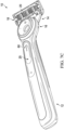
FIG. 1 is a top perspective view of one possible embodiment of a personal care appliance having an attached cartridge. -
FIG. 2 is an enlarged perspective view of a proximal end portion of the personal care appliance with the cartridge detached. -
FIG. 3 is a perspective view of an electronic subassembly of the personal care appliance ofFIG. 1 . -
FIG. 4 is a cross section view of the personal care appliance, taken generally along the line 4-4 ofFIG.1 -
FIG. 5 . is a block diagram that depicts a method of resetting a digital counter according to one or more embodiments shown and described herein. -
FIG. 6 . is a block diagram that depicts another method of resetting a digital counter according to one or more embodiments shown and described herein. -
FIGS. 7A-7C are top perspective views of the personal care device ofFIG. 1 with having display notifications. - Referring to
FIGS. 1 and2 , one possible embodiment of the present disclosure is shown illustrating apersonal care appliance 10. Thepersonal care appliance 10 may include ahandle 12 having acoupler 14 at afirst end 16 of the handle. Acartridge 18 may be removably mounted to thecoupler 14. Thecartridge 18 may include one ormore blades 20 for shaving. Although thepersonal care appliance 10 shown is a shaving razor, it is understood the personal care appliance may also include toothbrushes or other cosmetic devices having a replaceable cartridge. Thehandle 12 may include anoptical sensor subassembly 22. Theoptical sensor subassembly 22 may have at least one optical sensor (not shown) positioned within apocket 24 of ahousing 26. The at least one optical sensor (not shown) may be mounted to a printed circuit board 28 (e.g., a flexible printed circuit board) that extends from the coupler to a cavity within thehandle 12. It is understood that in certain embodiments, the printedcircuit board 28, as well as other electrical components may be positioned outside of thehandle 12 and sealed from water ingress. Aconsumer user interface 25 may be operably connected to a control circuit (not shown). In certain embodiments, theconsumer user interface 25 may be positioned on thehandle 12. The consumer user interface (e.g., a touch screen) may provide information to the user and receive input from the user regarding the function of thepersonal care appliance 10. It is understood that theconsumer user interface 25 may also be physically separated from thehandle 12, such as on a smart device (e.g., a phone or watch) or computer in the form of an app or a push notification requesting an input from the user. In such situations the control circuit (not shown) may still be operably connected to theuser interface 25 when thehandle 12 is a connected handle that is wirelessly or wire connected to the smart device or computer having the consumer interface. The communication betweenhandle 12 anduser interface 25 may happen directly (e.g., peer-to-peer) or via an intermediate cloud service. - The
cartridge 18 may define anopening 30 dimensioned to receive thecoupler 14. As will be explained in greater detail below, theopening 30 may be defined by anopaque surface 32 that covers the pocket 24 (e.g., in a planar direction) and the optical sensor (not shown) when thecartridge 18 is properly mounted to thecoupler 14. It is understood that tolerances may still allow for small gaps, thus it is understood thepocket 24 may not be completely covered. Theopaque surface 32 may prevent any ambient light from reaching the optical sensor and may also prevent light from reflecting light towards the optical sensor (not shown). When thecartridge 18 is removed from thecoupler 14, ambient light may reach theoptical sensor 38. - Referring to
FIG. 3 , a perspective view of anelectronic subassembly 34 of thepersonal care appliance 10 ofFIG. 1 is illustrated. Theelectronic subassembly 34 may be positioned within thehandle 12 ofFIG. 1 . Theelectronic subassembly 34 may include a control circuit 36 (e.g., a microcontroller). Thecontrol circuit 36 may be in electrical communication with the printedcircuit board 28, which is in electrical communication with anoptical sensor 38 mounted to the printedcircuit board 28. Theoptical sensor 38 may produce one or more electrical output signals. For example, the optical sensor may produce an electrical output signal when ambient light is blocked from reaching the optical sensor 38 (e.g., thecartridge 18 is mounted to thecoupler 14, as shown inFIG. 1 ). Theoptical sensor 38 may also produce the electrical output signal when ambient light is received by the optical sensor 38 (e.g., thecartridge 18 is separated from thecoupler 14, as shown inFIG. 2 ). It is understood that the electrical output signal may change over time and as thecartridge 18 is mounted to thecoupler 14 and removed from thecoupler 14. - The
optical sensor 38 may be able to distinguish between a close to zero lux condition, in which thecartridge 18 is mounted to thecoupler 14 and the opaque surface blocks ambient light and a low lux condition (e.g., 1 lux) in which thecartridge 18 is not mounted to thecoupler 14, but thepersonal care appliance 10 is in a dimly lit room. It is understood it may be difficult to achieve an absolute dark condition, even with thecartridge 18 mounted to thecoupler 14. Accordingly, theoptical sensor 38 may send the electrical output signal to thecontrol circuit 36 that corresponds to a reading from about zero lux to about 0.5 lux. Thecontrol circuit 36 may compare the electrical output signal to one or more predetermined threshold values. For example, the electrical output signal may be compared to a predetermined valued stored by thecontrol circuit 36 that represents ambient light being blocked from the optical sensor. In certain embodiments, a first predetermined value may represent a condition of thecartridge 18 attached to thecoupler 14. If the electrical output signal is less than the first predetermined value, thecontrol circuit 36 may determine thecartridge 18 is attached to thecoupler 14. If the electrical output signal is greater than or equal the first predetermined value, then thecontrol circuit 36 may determine thecartridge 18 has been removed from thecoupler 14. As will explained in greater detail below, thecontrol circuit 36 may send various signals depending if it determines thecartridge 18 is attached or removed from thecoupler 14. - In certain embodiments, the first predetermined value may not be determined by the manufacturer. For example, the
control circuit 36 may run a diagnostic test to have the consumer determine the correct light level for the first predetermined value. The consumer user interface 25 (FIG. 1 ) may ask the consumer to remove thecartridge 18. The consumer may confirm via the consumer user interface 25 (FIG. 1 ) the cartridge 18 (FIG. 1 ) has been removed. Thecontrol circuit 36 may then have theoptical sensor 38 send the electrical output signal, which may be stored by thecontrol circuit 36. Theconsumer user interface 25 may then ask the consumer to attach thecartridge 18 to the coupler 14 (FIG. 1 ). The consumer may confirm via theconsumer user interface 25 thecartridge 18 is attached (FIG. 1 ). Thecontrol circuit 36 may then have theoptical sensor 38 send the electrical output signal again, which may be stored by thecontrol circuit 36. If the consumer starts using the personal care appliance 10 (FIG. 1 ) in different lighting conditions, then the consumer may run the diagnostic test again, but under the new lighting conditions. - Referring to
FIG. 4 , a cross section view of thepersonal care appliance 10, taken generally along the line 4-4 ofFIG.1 is illustrated.FIG. 4 shows thecartridge 18 mounted to thecoupler 14. Thecoupler 14 may be positioned within the opening 30 (FIG. 2 ) with theopaque surface 32 positioned over (i.e., covering) theoptical sensor 38. Thepocket 24 may be dimensioned to receive theoptical sensor 38. Theoptical sensor 38 may be positioned towards a lower portion 40 of thepocket 24 away from atop surface 42 of thecoupler 14 that is adjacent to theopaque surface 32. - The
optical sensor 38 may include an over moldedlight guide 44. Thelight guide 44 may facilitate guiding ambient light to theoptical sensor 38 and may also prevent theoptical sensor 38 from being damaged either physically (e.g., from being dropped) or chemically (e.g., by chemicals typically found in personal hygiene appliances). The light guide 48 may comprise a transparent or translucent material, which only influences the transmission of ambient light to theoptical sensor 38 to an irrelevant extent. For example, materials may include silicone, thermoplastic elastomers, various curable liquid adhesives and/or polycarbonate. A softer material, such as silicone having a shore A durometer of about 5 to about 70, more preferably in the 30 - 50 range, may also provide improved sealing characteristics against water ingress and allow for less stringent assembly tolerances (e.g., assembly of thelight guide 44 within the pocket 24). Thelight guide 44 may completely surround the optical sensor 38 (e.g., side surfaces and top surface). Thelight guide 44 may be inserted or positioned within thepocket 24 such that atop surface 46 is flush with thetop surface 42 of thecoupler 14. In certain embodiments, theoptical sensor 38 may be recessed (e.g., by about 0.1 mm to about 3.0 mm). A small recess or flush surface may help to accommodate tolerance variations or to prevent any ambient light from reaching the optical sensor when thecartridge 18 is mounted to thecoupler 14. - Referring back to
FIG. 1 and with additional reference toFIG. 5 , thepersonal care appliance 10 may include adigital counter 50 that can be reset.FIG. 5 illustrates a block diagram is shown depicting one possible embodiment of a method of resetting adigital counter 50. Thedigital counter 50 may generate usage data about the personal care appliance 10 (FIG. 1 ), such as count time (e.g., shaving duration), incidence of usage, or strokes (e.g., shaving strokes). Theoptical sensor 38 may send the electrical output signal to thecontrol circuit 36. Thecontrol circuit 36 may then compare the electrical output signal to the first predetermined threshold value stored in thecontrol circuit 36. In certain embodiments, the first predetermined value for the electrical output signal may correspond to an irradiation of theoptical sensor 38 of about 0.5 mW/m2 or to an illumination of about 0.5 lux. In other embodiments, the first predetermined value may correspond to 1.0 mW/m2 or 1.0 lux. If the electrical output signal is below these values, thecartridge 18 may be attached to thecoupler 14. Theconsumer user interface 25 may display the status of the cartridge 18 (e.g., displaying words and/or a cartridge symbol). It is understood theconsumer user interface 25 may be positioned somewhere on thehandle 12 ofFIG. 1 ; however, in lieu of or in addition to, a smart device 52 (e.g., computer, tablet, phone or watch) may also be provided with consumer user interface. - When the
cartridge 18 is removed, the electrical output signal will be greater than or equal to the first predetermined value. Accordingly, thecontrol circuit 36 may send a signal to theconsumer user interface 25 on thehandle 12 and/or thesmart device 52 prompting a consumer to input a response, noting thecartridge 18 has been removed from thecoupler 14. Theconsumer user interface 25 and/or thesmart device 52 may then send a signal resetting thedigital counter 50. Alternatively, the control circuit may bypass theconsumer interface 25 and reset the shave stroke counter. However, this may not be advantageous, as thedigital counter 50 may be reset without the consumer's knowledge when thecartridge 18 is reattached after it was accidentally detached (e.g., during a drop). Theconsumer user interface 25 and/orsmart device 52 allows the user to confirm the status of thecartridge 18. - The
control circuit 36 comparing the electrical output signal to the predetermined value may work for a wide range of ambient light conditions. However, it may be possible for such a system to confuse the attachment condition of thecartridge 18 in very bright light conditions where thecontrol circuit 36 sends a signal that the cartridge is attached, but in reality, it is not. Accordingly, thecontrol circuit 36 may in lieu of or in addition to, may detect a change in the electrical output signal over time to compensate for such conditions. The time variable may be determined by the approximate amount of time it takes to detach thecartridge 18 from thecoupler 14 plus the time to attach thecartridge 18 to thecoupler 14. - If the control circuit detects a drop in the electrical output signal over time, then the
control circuit 36 may send a signal to theconsumer user interface 25 and/or thesmart device 52 prompting a consumer to input a response, noting thecartridge 18 has been removed from thecoupler 14. Theconsumer user interface 25 and/or thesmart device 52 may then send a signal to reset adigital counter 50. The amount of the change in the electrical output signal over time may also be stored by the control circuit 36 (e.g., as a second predetermined value). - Referring to
FIG. 6 , a block diagram is shown depicting another possible embodiment of a method of resetting thedigital counter 50. As previously described for the embodiment disclosed inFIG. 5 , theoptical sensor 38 may send an electrical output signal to thecontrol circuit 36. Thecontrol circuit 36 may then send a signal to thecloud 54. Thecloud 54 may use an algorithm to process the signal from thecontrol circuit 36 along with additional (e.g., usage information provided by the consumer and/or the control circuit 36). Thecloud 54 may then send a signal to the consumer user inter face 25 and/or thesmart device 52 notifying the user and requesting confirmation. The consumer may provide an input to the consumer user inter face 25 and/or thesmart device 52 to reset thedigital counter 50. - Referring to
FIGS. 7A ,7B and7C theconsumer user interface 25 of thehandle 12 of thepersonal care appliance 10 may display one or more notifications to the user. For example, theconsumer user interface 25 may display acartridge removal notification 56, such as an icon, informing the user that thecartridge 18 has been removed, as shown inFIG. 7A . Theconsumer user interface 25 may display acartridge attachment notification 58, such as an icon, informing the user that thecartridge 18 is successfully attached and is ready for use. Theconsumer user interface 25 may change the display from thecartridge attachment notification 56 to thecartridge removal notification 56 based on the input from the control circuit 36 (FIG. 5 ) or the cloud 54 (FIG. 6 ). When thecartridge 18 is reattached or replaced with anew cartridge 18, the consumer user interface may display aninput request notification 60 of a cartridge replacement condition, such as an icon, requesting confirmation from the user that thecartridge 18 has been replaced. If the consumer inputs thecartridge 18 has been replaced, a signal may be sent to reset the digital counter (FIGS. 5 and 6 ). - While particular embodiments of the present invention have been illustrated and described, it would be obvious to those skilled in the art that various other changes and modifications can be made without departing from the scope of the invention. The scope of protection of the current invention is defined by the appended claims.
Claims (15)
- A personal care appliance (10) comprising:a handle (12) having a coupler (14) at a first end (16);a control circuit (36) positioned within the handle;a consumer user interface (25) operably connected to the control circuit;a digital counter (50) operably connected to the control circuit;an optical sensor (38) mounted to the coupler that is configured to send an electrical output signal to the control circuit,a cartridge (18) configured to be removably mounted to the coupler, the cartridge having an opaque surface (32) covering the optical sensor and blocking ambient light from reaching the optical sensor when mounted to the coupler, wherein the control circuit is configured to determine an attachment status of the cartridge by comparing the electrical output signal to one or more predetermined thresholds or by detecting a change over time in the electrical output signal from the optical sensor.
- The personal care appliance (10) of claim 1 wherein the consumer user interface (25) is on the handle (12).
- The personal care appliance (10) according to any one of the preceding claims wherein the consumer user interface (25) is a smart device.
- The personal care appliance (10) according to any one of the preceding wherein the control circuit (36) is configured to send a signal to at least one of the consumer user interface (25) and the digital counter (50) if the electrical output signal exceeds the predetermined value.
- The personal care appliance (10) according to any one of the preceding claims wherein the control circuit (36) is configured to send a signal to at least one of the consumer user interface (25) and the digital counter (50) if the control circuit (36) detects a change in the electrical output signal over time.
- The personal care appliance (10) according to any one of the preceding claims wherein the control circuit (36) is configured to send a signal to the consumer user interface (25) if the control circuit detects a change in the electrical output signal over time and the electrical output signal exceeds the predetermined value.
- The personal care appliance (10) according to any one of the preceding claims wherein the optical sensor (38) is positioned within a pocket (24) of the coupler (14).
- The personal care appliance (10) according to any one of the preceding claims further comprising a light guide (44) covering the optical sensor (38).
- The personal care appliance (10) of claim 8 wherein the light guide (44) comprises a transparent material that fills the pocket (24).
- The personal care appliance (10) of claim 8 wherein the opaque surface (32) contacts the light guide (44).
- The personal care appliance (10) according to any one of the preceding claims wherein the optical sensor (38) is mounted to a printed circuit board (28) and a light guide (44) is positioned around the optical sensor and at least a portion of the printed circuit board.
- The personal care appliance (10) according to any one of the preceding claims wherein the digital counter (50) is reset in response to a signal sent from the consumer user interface.
- The personal care appliance (10) according to any one of the preceding claims wherein the control circuit (36) is configured to update the predetermined threshold value.
- The personal care appliance (10) according to any one claims 1-12 wherein the predetermined threshold value is fixed.
- The personal care appliance (10) according to any one of the preceding claims wherein the coupler (14) does not have a light emitter.
Priority Applications (1)
| Application Number | Priority Date | Filing Date | Title |
|---|---|---|---|
| EP25180453.0A EP4585379A3 (en) | 2021-04-07 | 2022-04-05 | Personal care appliance |
Applications Claiming Priority (2)
| Application Number | Priority Date | Filing Date | Title |
|---|---|---|---|
| US17/224,718 US11389980B1 (en) | 2021-04-07 | 2021-04-07 | Personal care appliance |
| PCT/US2022/071529 WO2022217211A1 (en) | 2021-04-07 | 2022-04-05 | Personal care appliance |
Related Child Applications (2)
| Application Number | Title | Priority Date | Filing Date |
|---|---|---|---|
| EP25180453.0A Division-Into EP4585379A3 (en) | 2021-04-07 | 2022-04-05 | Personal care appliance |
| EP25180453.0A Division EP4585379A3 (en) | 2021-04-07 | 2022-04-05 | Personal care appliance |
Publications (2)
| Publication Number | Publication Date |
|---|---|
| EP4319947A1 EP4319947A1 (en) | 2024-02-14 |
| EP4319947B1 true EP4319947B1 (en) | 2025-07-09 |
Family
ID=81386908
Family Applications (2)
| Application Number | Title | Priority Date | Filing Date |
|---|---|---|---|
| EP22719190.5A Active EP4319947B1 (en) | 2021-04-07 | 2022-04-05 | Personal care appliance |
| EP25180453.0A Pending EP4585379A3 (en) | 2021-04-07 | 2022-04-05 | Personal care appliance |
Family Applications After (1)
| Application Number | Title | Priority Date | Filing Date |
|---|---|---|---|
| EP25180453.0A Pending EP4585379A3 (en) | 2021-04-07 | 2022-04-05 | Personal care appliance |
Country Status (5)
| Country | Link |
|---|---|
| US (1) | US11389980B1 (en) |
| EP (2) | EP4319947B1 (en) |
| CN (1) | CN117157176A (en) |
| CA (1) | CA3213307A1 (en) |
| WO (1) | WO2022217211A1 (en) |
Families Citing this family (9)
| Publication number | Priority date | Publication date | Assignee | Title |
|---|---|---|---|---|
| USD905341S1 (en) * | 2018-02-28 | 2020-12-15 | The Gillette Company Llc | Razor handle |
| USD882873S1 (en) | 2018-03-30 | 2020-04-28 | The Gillette Company Llc | Shaving razor |
| USD912326S1 (en) | 2018-03-30 | 2021-03-02 | The Gillette Company Llc | Handle for a shaving razor |
| USD914289S1 (en) * | 2018-03-30 | 2021-03-23 | The Gillette Company Llc | Handle for a shaving razor |
| EP3782778A1 (en) * | 2019-08-20 | 2021-02-24 | Koninklijke Philips N.V. | Handheld personal care device with a light indicator for indicating an operational condition |
| US12233566B2 (en) * | 2021-04-07 | 2025-02-25 | The Gillette Company Llc | Personal care appliance |
| US12005596B2 (en) * | 2021-04-07 | 2024-06-11 | The Gillette Company Llc | Personal care appliance and a method of assembling |
| US11794365B2 (en) | 2021-10-01 | 2023-10-24 | The Gillette Company Llc | Personal care appliance |
| US11725811B2 (en) * | 2021-10-01 | 2023-08-15 | The Gillette Company Llc | Consumer appliance |
Family Cites Families (12)
| Publication number | Priority date | Publication date | Assignee | Title |
|---|---|---|---|---|
| US5347715A (en) * | 1993-09-14 | 1994-09-20 | Friedland Donald H | Blade shave counter |
| JPH1147463A (en) * | 1997-08-04 | 1999-02-23 | Izumi Prod Co | Electric razor |
| US20040098862A1 (en) * | 2002-08-21 | 2004-05-27 | Eveready Battery Company, Inc. | Razor system having razor sensors |
| US7367126B2 (en) * | 2005-09-06 | 2008-05-06 | The Gillette Company | Powered wet-shaving razor |
| US20070050995A1 (en) * | 2005-09-06 | 2007-03-08 | Fred Schnak | Razors |
| US8230600B2 (en) * | 2007-09-17 | 2012-07-31 | The Gillette Company | Cartridge detachment sensor |
| EP3109016B1 (en) * | 2015-06-25 | 2018-03-07 | The Gillette Company LLC | Heating element for a shaving razor |
| US10298471B2 (en) * | 2015-10-05 | 2019-05-21 | The Gillette Company Llc | Systems and methods for providing device usage data |
| US20190224869A1 (en) * | 2018-01-19 | 2019-07-25 | The Gillette Company Llc | Shaving appliance including a notification circuit for communicating cumulative shave event information |
| KR20210013023A (en) * | 2018-05-21 | 2021-02-03 | 빅-비올렉스 에스아 | System and method for providing speech recognition orders for replacement shaving cartridges |
| KR20210035084A (en) * | 2018-07-31 | 2021-03-31 | 빅-비올렉스 에스아 | Device for evaluating the condition of the shaving laser cartridge |
| WO2020206192A1 (en) * | 2019-04-05 | 2020-10-08 | The Gillette Company Llc | Skin treatment personal care device and method of manufacture |
-
2021
- 2021-04-07 US US17/224,718 patent/US11389980B1/en active Active
-
2022
- 2022-04-05 CN CN202280025277.2A patent/CN117157176A/en active Pending
- 2022-04-05 CA CA3213307A patent/CA3213307A1/en active Pending
- 2022-04-05 EP EP22719190.5A patent/EP4319947B1/en active Active
- 2022-04-05 WO PCT/US2022/071529 patent/WO2022217211A1/en not_active Ceased
- 2022-04-05 EP EP25180453.0A patent/EP4585379A3/en active Pending
Also Published As
| Publication number | Publication date |
|---|---|
| WO2022217211A1 (en) | 2022-10-13 |
| CN117157176A (en) | 2023-12-01 |
| EP4319947A1 (en) | 2024-02-14 |
| EP4585379A3 (en) | 2025-09-03 |
| EP4585379A2 (en) | 2025-07-16 |
| US11389980B1 (en) | 2022-07-19 |
| CA3213307A1 (en) | 2022-10-13 |
Similar Documents
| Publication | Publication Date | Title |
|---|---|---|
| US11389980B1 (en) | Personal care appliance | |
| US11881856B2 (en) | Method of resetting a digital counter for a personal care appliance | |
| RU2451596C2 (en) | Sensor of cartridge disconnection | |
| KR20100043283A (en) | Sensor for a razor | |
| JP4959705B2 (en) | Razor | |
| CN109858297B (en) | Information reading apparatus | |
| JP2010538692A (en) | Cartridge life indicator | |
| KR20080035028A (en) | Electric Driven Wet Shaver | |
| EP2144045A1 (en) | Digital Type Anti-Glare Device Using a Touchscreen and Method of Controlling the Same | |
| JP6804892B2 (en) | Electrical equipment | |
| EP4408630B1 (en) | Consumer appliance | |
| US11794365B2 (en) | Personal care appliance | |
| JP4449369B2 (en) | switch | |
| JP6069445B2 (en) | Stop switch device |
Legal Events
| Date | Code | Title | Description |
|---|---|---|---|
| STAA | Information on the status of an ep patent application or granted ep patent |
Free format text: STATUS: UNKNOWN |
|
| STAA | Information on the status of an ep patent application or granted ep patent |
Free format text: STATUS: THE INTERNATIONAL PUBLICATION HAS BEEN MADE |
|
| PUAI | Public reference made under article 153(3) epc to a published international application that has entered the european phase |
Free format text: ORIGINAL CODE: 0009012 |
|
| STAA | Information on the status of an ep patent application or granted ep patent |
Free format text: STATUS: REQUEST FOR EXAMINATION WAS MADE |
|
| 17P | Request for examination filed |
Effective date: 20231002 |
|
| AK | Designated contracting states |
Kind code of ref document: A1 Designated state(s): AL AT BE BG CH CY CZ DE DK EE ES FI FR GB GR HR HU IE IS IT LI LT LU LV MC MK MT NL NO PL PT RO RS SE SI SK SM TR |
|
| DAV | Request for validation of the european patent (deleted) | ||
| DAX | Request for extension of the european patent (deleted) | ||
| GRAP | Despatch of communication of intention to grant a patent |
Free format text: ORIGINAL CODE: EPIDOSNIGR1 |
|
| STAA | Information on the status of an ep patent application or granted ep patent |
Free format text: STATUS: GRANT OF PATENT IS INTENDED |
|
| INTG | Intention to grant announced |
Effective date: 20250203 |
|
| P01 | Opt-out of the competence of the unified patent court (upc) registered |
Free format text: CASE NUMBER: APP_19384/2025 Effective date: 20250423 |
|
| GRAS | Grant fee paid |
Free format text: ORIGINAL CODE: EPIDOSNIGR3 |
|
| GRAA | (expected) grant |
Free format text: ORIGINAL CODE: 0009210 |
|
| STAA | Information on the status of an ep patent application or granted ep patent |
Free format text: STATUS: THE PATENT HAS BEEN GRANTED |
|
| AK | Designated contracting states |
Kind code of ref document: B1 Designated state(s): AL AT BE BG CH CY CZ DE DK EE ES FI FR GB GR HR HU IE IS IT LI LT LU LV MC MK MT NL NO PL PT RO RS SE SI SK SM TR |
|
| REG | Reference to a national code |
Ref country code: GB Ref legal event code: FG4D |
|
| REG | Reference to a national code |
Ref country code: CH Ref legal event code: EP |
|
| REG | Reference to a national code |
Ref country code: IE Ref legal event code: FG4D |
|
| REG | Reference to a national code |
Ref country code: DE Ref legal event code: R096 Ref document number: 602022017313 Country of ref document: DE |
|
| REG | Reference to a national code |
Ref country code: NL Ref legal event code: MP Effective date: 20250709 |
|
| PG25 | Lapsed in a contracting state [announced via postgrant information from national office to epo] |
Ref country code: PT Free format text: LAPSE BECAUSE OF FAILURE TO SUBMIT A TRANSLATION OF THE DESCRIPTION OR TO PAY THE FEE WITHIN THE PRESCRIBED TIME-LIMIT Effective date: 20251110 |
|
| PG25 | Lapsed in a contracting state [announced via postgrant information from national office to epo] |
Ref country code: NL Free format text: LAPSE BECAUSE OF FAILURE TO SUBMIT A TRANSLATION OF THE DESCRIPTION OR TO PAY THE FEE WITHIN THE PRESCRIBED TIME-LIMIT Effective date: 20250709 |
|
| REG | Reference to a national code |
Ref country code: AT Ref legal event code: MK05 Ref document number: 1811442 Country of ref document: AT Kind code of ref document: T Effective date: 20250709 |
|
| PG25 | Lapsed in a contracting state [announced via postgrant information from national office to epo] |
Ref country code: IS Free format text: LAPSE BECAUSE OF FAILURE TO SUBMIT A TRANSLATION OF THE DESCRIPTION OR TO PAY THE FEE WITHIN THE PRESCRIBED TIME-LIMIT Effective date: 20251109 |
|
| PG25 | Lapsed in a contracting state [announced via postgrant information from national office to epo] |
Ref country code: NO Free format text: LAPSE BECAUSE OF FAILURE TO SUBMIT A TRANSLATION OF THE DESCRIPTION OR TO PAY THE FEE WITHIN THE PRESCRIBED TIME-LIMIT Effective date: 20251009 |
|
| REG | Reference to a national code |
Ref country code: LT Ref legal event code: MG9D |
|
| PG25 | Lapsed in a contracting state [announced via postgrant information from national office to epo] |
Ref country code: AT Free format text: LAPSE BECAUSE OF FAILURE TO SUBMIT A TRANSLATION OF THE DESCRIPTION OR TO PAY THE FEE WITHIN THE PRESCRIBED TIME-LIMIT Effective date: 20250709 |
|
| PG25 | Lapsed in a contracting state [announced via postgrant information from national office to epo] |
Ref country code: FI Free format text: LAPSE BECAUSE OF FAILURE TO SUBMIT A TRANSLATION OF THE DESCRIPTION OR TO PAY THE FEE WITHIN THE PRESCRIBED TIME-LIMIT Effective date: 20250709 |
|
| PG25 | Lapsed in a contracting state [announced via postgrant information from national office to epo] |
Ref country code: HR Free format text: LAPSE BECAUSE OF FAILURE TO SUBMIT A TRANSLATION OF THE DESCRIPTION OR TO PAY THE FEE WITHIN THE PRESCRIBED TIME-LIMIT Effective date: 20250709 |
|
| PG25 | Lapsed in a contracting state [announced via postgrant information from national office to epo] |
Ref country code: GR Free format text: LAPSE BECAUSE OF FAILURE TO SUBMIT A TRANSLATION OF THE DESCRIPTION OR TO PAY THE FEE WITHIN THE PRESCRIBED TIME-LIMIT Effective date: 20251010 |
|
| PG25 | Lapsed in a contracting state [announced via postgrant information from national office to epo] |
Ref country code: SE Free format text: LAPSE BECAUSE OF FAILURE TO SUBMIT A TRANSLATION OF THE DESCRIPTION OR TO PAY THE FEE WITHIN THE PRESCRIBED TIME-LIMIT Effective date: 20250709 |
|
| PG25 | Lapsed in a contracting state [announced via postgrant information from national office to epo] |
Ref country code: LV Free format text: LAPSE BECAUSE OF FAILURE TO SUBMIT A TRANSLATION OF THE DESCRIPTION OR TO PAY THE FEE WITHIN THE PRESCRIBED TIME-LIMIT Effective date: 20250709 |
|
| PG25 | Lapsed in a contracting state [announced via postgrant information from national office to epo] |
Ref country code: BG Free format text: LAPSE BECAUSE OF FAILURE TO SUBMIT A TRANSLATION OF THE DESCRIPTION OR TO PAY THE FEE WITHIN THE PRESCRIBED TIME-LIMIT Effective date: 20250709 Ref country code: PL Free format text: LAPSE BECAUSE OF FAILURE TO SUBMIT A TRANSLATION OF THE DESCRIPTION OR TO PAY THE FEE WITHIN THE PRESCRIBED TIME-LIMIT Effective date: 20250709 |
|
| PG25 | Lapsed in a contracting state [announced via postgrant information from national office to epo] |
Ref country code: RS Free format text: LAPSE BECAUSE OF FAILURE TO SUBMIT A TRANSLATION OF THE DESCRIPTION OR TO PAY THE FEE WITHIN THE PRESCRIBED TIME-LIMIT Effective date: 20251009 |
|
| PG25 | Lapsed in a contracting state [announced via postgrant information from national office to epo] |
Ref country code: ES Free format text: LAPSE BECAUSE OF FAILURE TO SUBMIT A TRANSLATION OF THE DESCRIPTION OR TO PAY THE FEE WITHIN THE PRESCRIBED TIME-LIMIT Effective date: 20250709 |
|
| PG25 | Lapsed in a contracting state [announced via postgrant information from national office to epo] |
Ref country code: SM Free format text: LAPSE BECAUSE OF FAILURE TO SUBMIT A TRANSLATION OF THE DESCRIPTION OR TO PAY THE FEE WITHIN THE PRESCRIBED TIME-LIMIT Effective date: 20250709 |
|
| PG25 | Lapsed in a contracting state [announced via postgrant information from national office to epo] |
Ref country code: DK Free format text: LAPSE BECAUSE OF FAILURE TO SUBMIT A TRANSLATION OF THE DESCRIPTION OR TO PAY THE FEE WITHIN THE PRESCRIBED TIME-LIMIT Effective date: 20250709 |
|
| PG25 | Lapsed in a contracting state [announced via postgrant information from national office to epo] |
Ref country code: IT Free format text: LAPSE BECAUSE OF FAILURE TO SUBMIT A TRANSLATION OF THE DESCRIPTION OR TO PAY THE FEE WITHIN THE PRESCRIBED TIME-LIMIT Effective date: 20250709 |
|
| PG25 | Lapsed in a contracting state [announced via postgrant information from national office to epo] |
Ref country code: CZ Free format text: LAPSE BECAUSE OF FAILURE TO SUBMIT A TRANSLATION OF THE DESCRIPTION OR TO PAY THE FEE WITHIN THE PRESCRIBED TIME-LIMIT Effective date: 20250709 |
|
| PG25 | Lapsed in a contracting state [announced via postgrant information from national office to epo] |
Ref country code: EE Free format text: LAPSE BECAUSE OF FAILURE TO SUBMIT A TRANSLATION OF THE DESCRIPTION OR TO PAY THE FEE WITHIN THE PRESCRIBED TIME-LIMIT Effective date: 20250709 Ref country code: SK Free format text: LAPSE BECAUSE OF FAILURE TO SUBMIT A TRANSLATION OF THE DESCRIPTION OR TO PAY THE FEE WITHIN THE PRESCRIBED TIME-LIMIT Effective date: 20250709 |
|
| PLBE | No opposition filed within time limit |
Free format text: ORIGINAL CODE: 0009261 |
|
| STAA | Information on the status of an ep patent application or granted ep patent |
Free format text: STATUS: NO OPPOSITION FILED WITHIN TIME LIMIT |