EP4319518A1 - Casing and power conversion device - Google Patents
Casing and power conversion device Download PDFInfo
- Publication number
- EP4319518A1 EP4319518A1 EP22784343.0A EP22784343A EP4319518A1 EP 4319518 A1 EP4319518 A1 EP 4319518A1 EP 22784343 A EP22784343 A EP 22784343A EP 4319518 A1 EP4319518 A1 EP 4319518A1
- Authority
- EP
- European Patent Office
- Prior art keywords
- flow path
- capacitor
- power module
- path forming
- forming portion
- Prior art date
- Legal status (The legal status is an assumption and is not a legal conclusion. Google has not performed a legal analysis and makes no representation as to the accuracy of the status listed.)
- Withdrawn
Links
Images




Classifications
-
- H—ELECTRICITY
- H05—ELECTRIC TECHNIQUES NOT OTHERWISE PROVIDED FOR
- H05K—PRINTED CIRCUITS; CASINGS OR CONSTRUCTIONAL DETAILS OF ELECTRIC APPARATUS; MANUFACTURE OF ASSEMBLAGES OF ELECTRICAL COMPONENTS
- H05K7/00—Constructional details common to different types of electric apparatus
- H05K7/20—Modifications to facilitate cooling, ventilating, or heating
- H05K7/2089—Modifications to facilitate cooling, ventilating, or heating for power electronics, e.g. for inverters for controlling motor
- H05K7/20927—Liquid coolant without phase change
-
- H—ELECTRICITY
- H02—GENERATION; CONVERSION OR DISTRIBUTION OF ELECTRIC POWER
- H02M—APPARATUS FOR CONVERSION BETWEEN AC AND AC, BETWEEN AC AND DC, OR BETWEEN DC AND DC, AND FOR USE WITH MAINS OR SIMILAR POWER SUPPLY SYSTEMS; CONVERSION OF DC OR AC INPUT POWER INTO SURGE OUTPUT POWER; CONTROL OR REGULATION THEREOF
- H02M7/00—Conversion of AC power input into DC power output; Conversion of DC power input into AC power output
- H02M7/003—Constructional details, e.g. physical layout, assembly, wiring or busbar connections
Definitions
- the present disclosure relates to a casing and a power conversion device.
- a coolant such as cooling water may be used to cool a power module. Further, in such power conversion devices, the temperature of a capacitor may rise in addition to the power module and the capacitor may also need to be cooled.
- Patent Document 1 discloses a structure in which a cooling water channel is provided around a capacitor provided inside a casing of a power conversion device to cool the capacitor.
- Patent Document 1 Japanese Unexamined Patent Application, First Publication No. 2015-156798
- the present disclosure has been made in view of the above-described circumstances and an object thereof is to provide a casing and a power conversion device capable of suppressing an increase in size while efficiently cooling a capacitor.
- a casing according to a first aspect of the present disclosure is a casing of a power conversion device with a capacitor and a power module, including: a coolant flow path forming portion in which a flow path of coolant is formed; a capacitor storage portion which is integrally formed with a part of the coolant flow path forming portion and in which a capacitor storage space of the capacitor is formed; and a cover portion defining a power module storage space storing at least the power module together with the remaining part of the coolant flow path forming portion and the capacitor storage portion, wherein the coolant flow path forming portion includes a capacitor cooling unit which is configured to cool the capacitor storage portion and a power module cooling unit which is configured to cool the power module.
- a power conversion device includes: the above mentioned casing; a capacitor which is stored in the capacitor storage space; and a power module which is stored in the power module storage space.
- a casing and a power conversion device of the present disclosure it is possible to suppress an increase in size while efficiently cooling a capacitor.
- FIG. 1 is a perspective view of the power conversion device of the first embodiment of the present disclosure.
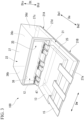
- FIG. 2 is a perspective view of the power conversion device of the first embodiment of the present disclosure and shows a state in which a cover is removed.
- FIG. 3 is a perspective view of the power conversion device of the first embodiment of the present disclosure and shows a state in which a control board and a current sensor of FIG. 2 are removed.
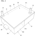
- FIG. 4 is a bottom view of the power conversion device of FIG. 1 .
- a power conversion device 100 of the first embodiment is the power conversion device 100 used as an inverter for converting DC power into AC power, a converter for converting AC power into DC power, or the like.
- This power conversion device 100 can be used, for example, as a power conversion device or the like that controls a three-phase brushless motor that is a drive source of an electric vehicle.
- the power conversion device 100 of this embodiment includes a casing 11, a capacitor 12, a power module 13, a control board 14, a bus bar 15, and a current sensor 16.
- the casing 11 is for storing each of the capacitor 12, the power module 13, the control board 14, and the current sensor 16.
- the casing 11 can be formed of, for example, metal or synthetic resin having high thermal conductivity.
- the casing 11 includes a coolant flow path forming portion 21, a capacitor storage portion 22, and a cover portion 23.
- the coolant flow path forming portion 21 constitutes a flow path R (which will be described later) through which a coolant flows.
- the coolant flow path forming portion 21 of this embodiment includes a first wall portion 25 and a second wall portion 26 each having a rectangular outline in plan view.
- the coolant flow path forming portion 21 further includes four side walls 27a to 27d which connect the first wall portion 25 and the second wall portion 26. Additionally, in the following description, the direction in which the long sides of the first wall portion 25 and the second wall portion 26 of the coolant flow path forming portion 21 extend is referred to as the longitudinal direction Da and the direction in which the short sides of the rectangle extend is referred to as the width direction Dw.
- the thickness direction Dt the direction perpendicular to the first wall portion 25 and the second wall portion 26 is referred to as the thickness direction Dt
- the side away from the first wall portion 25 in the thickness direction is referred to as the first side Dtu in the thickness direction
- the side away from the second wall portion 26 is referred to as the second side Dtd in the thickness direction.
- FIG. 5 is a perspective view showing a state in which a lid of FIG. 4 is removed.
- the coolant flow path forming portion 21 of this embodiment includes a coolant flow path forming portion body 28 and a lid portion 29.
- the coolant flow path forming portion body 28 includes a flow path recess portion 30 which opens to the side of the second wall portion 26.
- the lid portion 29 includes a lid body 31 which is formed in a flat plate shape and a coolant inlet 32 and a coolant outlet 33 which are attached to the lid body 31.
- the lid body 31 blocks the flow path recess portion 30.
- the lid body 31 of this embodiment constitutes the second wall portion 26 of the coolant flow path forming portion 21 while blocking the flow path recess portion 30 of the coolant flow path forming portion body 28.
- Each of the coolant inlet 32 and the coolant outlet 33 extends from the lid body 31 to the second side in the thickness direction.
- the coolant inlet 32 and the coolant outlet 33 communicate with the inside and the outside of the coolant flow path forming portion 21.
- the coolant inlet 32 is an inlet for supplying a coolant to the flow path R formed inside the coolant flow path forming portion 21 and the coolant outlet 33 is an outlet for discharging the coolant flowed through the flow path R formed inside the coolant flow path forming portion 21 to the outside of the coolant flow path forming portion 21.
- the coolant inlet 32 and the coolant outlet 33 of this embodiment are arranged at diagonal positions of the rectangle in plan view in the lid body 31. That is, when the coolant flows from the coolant inlet 32, the coolant flows through the flow path R inside the coolant flow path forming portion 21 and then is discharged from the coolant outlet 33 to the outside of the coolant flow path forming portion 21.
- the capacitor storage portion 22 constitutes a capacitor storage space 35 which stores the capacitor 12.
- the capacitor storage portion 22 is integrally formed with a part of the coolant flow path forming portion 21.
- the capacitor storage portion 22 constitutes the capacitor storage space 35 storing the capacitor 12 together with the first wall portion 25 of the coolant flow path forming portion 21.
- the capacitor storage portion 22 of this embodiment includes two traverse side walls 36b and 36d which extend toward the first side Dtu in the thickness direction in parallel to a side wall 27b (see FIG.
- the capacitor storage portion 22 further includes an opening portion 38 on the side opposite to the longitudinal side wall 36c in the longitudinal direction Da. This opening portion 38 faces the second side Da2 in the longitudinal direction Da.
- the capacitor 12 can be stored in the capacitor storage space 35 inside the capacitor storage portion 22 through this opening portion 38.
- the longitudinal side wall 36c of this embodiment is provided with a terminal portion 39 for electrically connecting the capacitor 12 and the outside of the capacitor storage portion 22.
- the capacitor storage portion 22 of this embodiment is provided with a partition wall 41 which divides the capacitor storage space 35 into a plurality of sections. These partition walls 41 are connected to at least one of the traverse side walls 36b and 36d, the longitudinal side wall 36c, the ceiling wall 37, and the coolant flow path forming portion body 28. In other words, the heat transferred to the partition wall 41 is indirectly transferred to the coolant flow path forming portion body 28 via the traverse side walls 36b and 36d, the longitudinal side wall 36c, and the ceiling wall 37 or is directly transferred to the coolant flow path forming portion body 28.
- the partition wall 41 of this embodiment is provided with a through hole (not shown) and a wiring (not shown) connected to the capacitor 12 is inserted through the through hole. Additionally, the partition wall 41 may be provided appropriately or may be omitted.
- the cover portion 23 defines at least a power module storage space 42 storing the power module 13 together with the remainder of the coolant flow path forming portion 21 not provided with the capacitor storage portion 22 and the capacitor storage portion 22.
- the remainder of the coolant flow path forming portion 21 is a portion excluding a portion integrally formed with the capacitor storage portion 22 in the coolant flow path forming portion 21.
- the cover portion 23 is attachable to and detachable from the coolant flow path forming portion 21 and the capacitor storage portion 22.
- the cover portion 23 of this embodiment includes two traverse cover side walls 43b and 43d which extend to the first side Dtu in the thickness direction in parallel to the side walls 27b and 27d in the width direction Dw of the remainder of the coolant flow path forming portion 21 while being attached to the remainder of the coolant flow path forming portion 21 and the capacitor storage portion 22 to define the power module storage space 42 (in other words, in a blocked state), one longitudinal cover side wall 43a which extends to the first side Dtu in the thickness direction in parallel to the side wall 27a located on the second side Da2 in the longitudinal direction Da of the coolant flow path forming portion 21, edge portions of the traverse cover side walls 43b and 43d on the first side Dtu in the thickness direction, and a cover ceiling wall 44 which connects the edge portions of the longitudinal cover side wall 43a on the first side in the thickness direction and extends in the longitudinal direction Da and the width direction Dw.
- the longitudinal cover side wall 43a is provided with a plurality of through holes 45 through which a conductor such as a bus bar 15 electrically connecting the power module 13 and the outside of the casing 11 passes. Then, each penetrating current sensor 16 is attached to the bus bar 15 of this embodiment and these current sensors 16 are stored in the power module storage space 42 together with the power module 13. Further, in this embodiment, the control board 14 controlling the operation of the power module 13 is also stored in the power module storage space 42.
- part of the coolant flow path forming portion 21 integrally formed with the capacitor storage portion 22 constitutes a capacitor cooling unit 21A and the remainder of the coolant flow path forming portion 21 excluding the capacitor cooling unit 21A constitutes a power module cooling unit 21B.
- the capacitor 12 removes, for example, high-frequency components from the external power input to the power conversion device 100.
- a film capacitor can be exemplified.
- the power conversion device 100 of this embodiment includes the plurality of capacitors 12 and all of these capacitors 12 are stored in the capacitor storage portion 22.
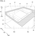
- FIG. 6 is a perspective view showing a partial cross-section of the capacitor storage portion of the first embodiment of the present disclosure.
- the capacitor storage portion 22 of this embodiment is filled with a filler 46 having exceptional thermal conductivity and high electrical insulation properties while storing the capacitor 12. That is, the filler 46 is in close contact with the outer surface of the capacitor 12 and the heat of the capacitor 12 is transferred to the capacitor storage portion 22 and the coolant flow path forming portion 21 via the filler 46.
- the filler 46 filled in the capacitor storage portion 22 for example, the filler 46 which flows into the capacitor storage portion 22 in a liquid state and then is solidified can be used.
- the power module 13 a plurality of power semiconductor elements such as surface-mounted power MOSFETs and IGBTs are mounted on a circuit board. As shown in FIG. 3 , the power module 13 capable of outputting three-phase power is exemplified in this embodiment.
- the power module 13 is installed inside the power module storage space 42 of the casing 11. More specifically, the power module 13 of this embodiment is fixed to the surface of the remainder of the coolant flow path forming portion 21. Then, the power module 13 of this embodiment is installed in a posture in which the extension direction of the circuit board matches the extension direction of the first wall portion 25 of the coolant flow path forming portion 21.
- the power module cooling unit 21B which is the remainder of the coolant flow path forming portion 21 includes a communication opening portion 47 which is formed on the surface of the coolant flow path forming portion body 28 to allow the power module storage space 42 and the flow path R inside the coolant flow path forming portion 21 to communicate with each other.
- the power module 13 of this embodiment is formed to be larger than the communication opening portion 47 and is fixed to the coolant flow path forming portion 21 to block the communication opening portion 47. Additionally, the periphery of the communication opening portion 47 is sealed so that the coolant does not leak from the gap between the communication opening portion 47 and the power module 13.
- the power module 13 further includes a cooling fin 48 for cooling a power semiconductor element.
- the cooling fin 48 is fixed to the rear surface of the circuit board facing the side opposite to the mounting surface of the power semiconductor element.
- the cooling fin 48 is electrically insulated from the circuit board and heat emitted from the power semiconductor element is transferred thereto.
- At least a part of the cooling fin 48 is located inside the flow path R of the coolant flow path forming portion 21 via the communication opening portion 47 of the coolant flow path forming portion 21. That is, the power semiconductor element and the coolant can indirectly exchange heat therebetween via the cooling fin 48 and the circuit board.
- the power module cooling unit 21B of the coolant flow path forming portion 21 includes a module cooling flow path 51 which communicates with the communication opening portion 47 as the flow path R.
- the cooling fin 48 of the power module 13 is disposed in this module cooling flow path 51.
- This module cooling flow path 51 is formed at a position overlapping the coolant inlet 32 when viewed from the thickness direction Dt and the coolant flows from the coolant inlet 32.
- the module cooling flow path 51 of this embodiment has the same rectangular shape as that of the communication opening portion 47 when viewed from the thickness direction Dt. Further, the module cooling flow path 51 of this embodiment has a rectangular shape elongated in the width direction Dw.
- module cooling flow path 51 of this embodiment is sandwiched between the cooling fin 48 and the lid portion 29 in the thickness direction Dt. Additionally, the module cooling flow path 51 is not limited to the above-described shape and may be appropriately formed according to, for example, the shape of the cooling fin 48.
- the capacitor cooling unit 21A includes a capacitor cooling flow path 52 which communicates with the downstream side of the module cooling flow path 51 of the power module cooling unit 21B.
- the capacitor cooling flow path 52 of this embodiment communicates with the module cooling flow path 51 via a connection flow path 53 located on one side in the width direction Dw and extending in the longitudinal direction.
- the capacitor cooling flow path 52 includes a capacitor flow path recess portion 54 which is the flow path recess portion 30, a first flow path wall 55 which extends from one side to the other side in the width direction Dw, and a second flow path wall 56 which extends from the other side to one side in the width direction Dw.
- An end portion 55t of the first flow path wall 55 is separated from an edge portion 57 on the other side in the width direction Dw of the capacitor flow path recess portion 54 and an end portion 56t of the second flow path wall 56 is separated from an edge portion 58 on one side in the width direction Dw of the capacitor flow path recess portion 54. Then, the first flow path wall 55 and the second flow path wall 56 are alternately formed at intervals in the longitudinal direction Da. Further, edge portions 55e and 56e of the first flow path wall 55 and the second flow path wall 56 on the side of the lid portion 29 are respectively in close contact with the lid portion 29.
- the coolant flowing through the capacitor cooling flow path 52 of the capacitor cooling unit 21A flows to the first side in the width direction Dw, flows to the second side in the width direction Dw, and then flows to the first side in the width direction Dw. In this way, the coolant flows in a meandering manner while changing direction repeatedly.
- the casing 11 of the first embodiment includes the coolant flow path forming portion 21, the capacitor storage portion 22, and the cover portion 23.
- the coolant flow path forming portion 21 forms the flow path R through which the coolant flows.
- the capacitor storage portion 22 is integrally formed with a part of the coolant flow path forming portion 21 and forms the capacitor storage space 35 storing the capacitor 12.
- the cover portion 23 defines at least the power module storage space 42 storing the power module 13 together with the remainder of the coolant flow path forming portion 21 and the capacitor storage portion 22.
- the coolant flow path forming portion 21 includes the capacitor cooling unit 21A which cools the capacitor storage portion 22 and the power module cooling unit 21B which cools the power module 13.
- the capacitor storage portion 22 and part of the coolant flow path forming portion 21 are integrally formed with each other, it is possible to define the capacitor storage space 35 by efficiently using a part of the coolant flow path forming portion 21.
- the power module storage space 42 is formed by efficiently using the remainder of the coolant flow path forming portion 21 and the capacitor storage portion 22 in addition to the cover portion 23, it is possible to form the power module storage space 42 in a compact size.
- the power module cooling unit 21B of the first embodiment further includes the communication opening portion 47 which allows the power module storage space 42 and the flow path R to communicate with each other.
- the cover portion 23 of the first embodiment includes a through hole 45 through which the bus bar 15 connected to the power module 13 is able to pass. Then, the power module storage space 42 is able to store the current sensor 16 that measures a current flowing through the bus bar 15.
- the capacitor storage portion 22 of the first embodiment includes the partition wall 41 which divides the capacitor storage space 35 into a plurality of sections.
- the capacitor storage space 35 of the first embodiment is filled with the filler 46.
- the filler 46 contacts the periphery of the capacitor 12 and the filler 46 contacts the capacitor cooling unit 21A and each wall portion (the traverse side walls 36b and 36d and the ceiling wall 37) of the capacitor storage portion 22. Therefore, since the heat of the capacitor 12 is transferred to each wall portion and the capacitor cooling unit 21A via the filler 46, it is possible to further improve the cooling efficiency compared to the case in which the filler 46 is not filled.
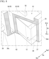
- FIG. 7 is a partially cross-sectional view of the coolant flow path forming portion of the second embodiment of the present disclosure.
- FIG. 8 is a main enlarged view of FIG. 7 .
- the power conversion device of this second embodiment includes the casing 11, the capacitor 12, the power module 13, the control board 14, the bus bar 15, and the current sensor 16 similarly to the power conversion device 100 of the first embodiment. Further, the casing 11 of the second embodiment includes the coolant flow path forming portion 21, the capacitor storage portion 22, and the cover portion 23.
- the coolant flow path forming portion 21 of this second embodiment includes the capacitor cooling unit 21A which is integrally formed with the capacitor storage portion 22 and the power module cooling unit 21B which cools the power module 13 similarly to the coolant flow path forming portion 21 of the first embodiment.
- the capacitor cooling unit 21A of this second embodiment includes a first flow path forming portion 61 and a second flow path forming portion 62.
- the first flow path forming portion 61 forms a first flow path 63 along the first wall portion 25 of the coolant flow path forming portion 21.
- the second flow path forming portion 62 communicates with the first flow path forming portion 61 and forms the second flow path 64 along the longitudinal side wall 36c of the capacitor storage portion 22.
- the second flow path forming portion 62 is integrally formed with the longitudinal side wall 36c of the capacitor storage portion 22.
- the second flow path forming portion 62 of this second embodiment forms the flow path R which extends from the most first side Da1 in the longitudinal direction to the first side Dtu in the thickness direction in the first flow path forming portion 61.
- Part of the coolant flowed through the first flow path 63 flows into the second flow path 64 formed by the second flow path forming portion 62.
- the coolant flowing into the second flow path 64 is discharged to the outside of the coolant flow path forming portion 21 from the coolant outlet 33 together with the coolant not flowing into the second flow path 64.
- the second flow path 64 is not limited to the case in which the second flow path is formed along the longitudinal side wall 36c.
- the second flow path 64 may be formed along, for example, one of two traverse side walls 36b and 36d. That is, the second flow path 64 may be formed along any one side wall among two traverse side walls 36b and 36d and the longitudinal side wall 36c. Furthermore, the second flow path 64 may be formed along any two or all side walls among two traverse side walls 36b and 36d and the longitudinal side wall 36c.
- the capacitor cooling unit 21A of the second embodiment includes the first flow path forming portion 61 which forms the first flow path 63 along the first wall portion 25 of the coolant flow path forming portion 21 and the second flow path forming portion 62 which communicates with the first flow path forming portion 61 and forms the second flow path 64 along the longitudinal side wall 36c of the capacitor storage portion 22.
- the capacitor storage portion 22 can be cooled not only from the side of the first wall portion 25 of the coolant flow path forming portion 21 but also the side of the longitudinal side wall 36c in the capacitor storage portion 22 in addition to the operation and effect of the first embodiment. As a result, it is possible to more efficiently cool the capacitor 12 stored in the capacitor storage portion 22 while suppressing an increase in size of the device.
- the shape of the casing 11 in plan view is not limited to the rectangular shape.
- the current sensor 16 may be disposed outside the casing 11. Further, in the first embodiment, although a case has been described in which the current sensor 16 is stored in the power module storage space 42, the current sensor 16 may be disposed outside the casing 11. Further, the control board 14 may also be disposed outside the casing 11.
- the partition wall 41 may be omitted.
- the filler may be omitted.
- the power module cooling unit 21B includes the communication opening portion 47 which allows the power module storage space 42 and the flow path R to communicate with each other, the communication opening portion 47 may be provided as necessary and, for example, the communication opening portion 47 may not be provided.
- the power conversion device 100 for example, an inverter device, a converter device, and a device obtained by combining the inverter and the converter are exemplified.
- the coolant flow path forming portion 21 it is possible to cool both the capacitor 12 and the power module 13 by the coolant flow path forming portion 21. Further, since the capacitor storage portion 22 and part of the coolant flow path forming portion 21 are integrally formed with each other, it is possible to define the capacitor storage space 35 by efficiently using part of the coolant flow path forming portion 21. Further, since the power module storage space 42 is formed by efficiently using the remainder of the coolant flow path forming portion 21 and the capacitor storage portion 22 in addition to the cover portion 23, it is possible to form the power module storage space 42 in a compact size.
- the casing 11 is the casing 11 of (1), wherein the capacitor cooling unit 21A may include the first flow path forming portion 61 forming the first flow path 63 along the first wall portion 25 of the coolant flow path forming portion 21 and the second flow path forming portion 62 communicating with the first flow path forming portion 61 and forming the second flow path 64 along the side wall of the capacitor storage portion 22.
- the capacitor storage portion 22 can be cooled not only from the side of the first wall portion 25 of the coolant flow path forming portion 21 but also the side of the longitudinal side wall 36c in the capacitor storage portion 22. As a result, it is possible to more efficiently cool the capacitor 12 stored in the capacitor storage portion 22 while suppressing an increase in size.
- the casing 11 is the casing 11 of (1) or (2), wherein the power module cooling unit 21B may include the communication opening portion 47 allowing the power module storage space 42 to communicate with the flow path R.
- the casing 11 is the casing 11 of any one of (1) to (3), wherein the cover portion 23 may include the through hole 45 through which a conductor to be connected to the power module 13 is passed, and wherein the power module storage space 42 may be allowed to store the current sensor 16 measuring a current flowing through the conductor.
- the current sensor 16 since it is possible to store the current sensor 16 in the power module storage space 42, it is also possible to cool the current sensor 16 by allowing, for example, the current sensor 16 to contact the coolant flow path forming portion 21.
- the installation space is small compared to the case in which a cooling mechanism for cooling the current sensor 16 is separately provided, it is possible to improve the degree of freedom when installing the casing 11.
- the casing 11 is the casing 11 of any one of (1) to (4), wherein the capacitor storage portion 22 may include the wall portion 41 dividing the capacitor storage space 35 into a plurality of sections.
- a partition wall can be exemplified.
- the heat of the capacitor 12 stored in the capacitor storage portion 22 is transferred to the capacitor cooling unit 21A via the partition wall 41.
- the partition wall 41 it is possible to more efficiently cool the capacitor 12.
- the power conversion device 100 includes: the casing 11 of any one of (1) to (5); the capacitor 12 which is stored in the capacitor storage space 35; and the power module 13 which is stored in the power module storage space 42.
- the power conversion device 100 including the capacitor 12 and the power module 13 can be made compact.
- the power conversion device 100 is the power conversion device 100 of (6), wherein the capacitor storage space 35 may be filled with the filler 46.
- the filler contacts the periphery of the capacitor 12 and the filler 46 contacts each wall portion of the capacitor storage portion 22. Therefore, since the heat of the capacitor 12 is transferred to the wall portion 41 and the capacitor cooling unit 21A via the filler, it is possible to further improve the cooling efficiency compared to the case in which the filler 46 is not filled.
- the present disclosure relates to a casing and a power conversion device. According to the casing of the present disclosure, it is possible to suppress an increase in size while efficiently cooling a capacitor.
Landscapes
- Engineering & Computer Science (AREA)
- Microelectronics & Electronic Packaging (AREA)
- Physics & Mathematics (AREA)
- Thermal Sciences (AREA)
- Power Engineering (AREA)
- Inverter Devices (AREA)
- Cooling Or The Like Of Electrical Apparatus (AREA)
Abstract
Description
- The present disclosure relates to a casing and a power conversion device.
- Priority is claimed on
Japanese Patent Application No. 2021-64920, filed April 6, 2021 - In power conversion devices such as inverters, a coolant such as cooling water may be used to cool a power module. Further, in such power conversion devices, the temperature of a capacitor may rise in addition to the power module and the capacitor may also need to be cooled.
-
Patent Document 1 discloses a structure in which a cooling water channel is provided around a capacitor provided inside a casing of a power conversion device to cool the capacitor. - Patent Document 1:
Japanese Unexamined Patent Application, First Publication No. 2015-156798 - However, when the cooling water channel is provided around the capacitor as in the power conversion device of
Patent Document 1, a space for providing the cooling water channel dedicated for the capacitor is required and hence a problem arises in that the casing of the power conversion device increases in size. - The present disclosure has been made in view of the above-described circumstances and an object thereof is to provide a casing and a power conversion device capable of suppressing an increase in size while efficiently cooling a capacitor.
- A casing according to a first aspect of the present disclosure is a casing of a power conversion device with a capacitor and a power module, including: a coolant flow path forming portion in which a flow path of coolant is formed; a capacitor storage portion which is integrally formed with a part of the coolant flow path forming portion and in which a capacitor storage space of the capacitor is formed; and a cover portion defining a power module storage space storing at least the power module together with the remaining part of the coolant flow path forming portion and the capacitor storage portion, wherein the coolant flow path forming portion includes a capacitor cooling unit which is configured to cool the capacitor storage portion and a power module cooling unit which is configured to cool the power module.
- A power conversion device according to a second aspect of the present disclosure includes: the above mentioned casing; a capacitor which is stored in the capacitor storage space; and a power module which is stored in the power module storage space.
- According to a casing and a power conversion device of the present disclosure, it is possible to suppress an increase in size while efficiently cooling a capacitor.
-
-
FIG. 1 is a perspective view of a power conversion device of a first embodiment of the present disclosure. -
FIG. 2 is a perspective view of the power conversion device of the first embodiment of the present disclosure and shows a state in which a cover is removed. -
FIG. 3 is a perspective view of the power conversion device of the first embodiment of the present disclosure and shows a state in which a control board and a current sensor ofFIG. 2 are removed. -
FIG. 4 is a bottom view of the power conversion device ofFIG. 1 . -
FIG. 5 is a perspective view showing a state in which a lid ofFIG. 4 is removed. -
FIG. 6 is a perspective view showing a partial cross-section of a capacitor storage portion of the first embodiment of the present disclosure. -
FIG. 7 is a partially cross-sectional view of a coolant flow path forming portion of a second embodiment of the present disclosure. -
FIG. 8 is a main enlarged view ofFIG. 7 . - Next, a casing and a power conversion device of a first embodiment of the present disclosure will be described with reference to the drawings.
FIG. 1 is a perspective view of the power conversion device of the first embodiment of the present disclosure.FIG. 2 is a perspective view of the power conversion device of the first embodiment of the present disclosure and shows a state in which a cover is removed.FIG. 3 is a perspective view of the power conversion device of the first embodiment of the present disclosure and shows a state in which a control board and a current sensor ofFIG. 2 are removed.FIG. 4 is a bottom view of the power conversion device ofFIG. 1 . - A
power conversion device 100 of the first embodiment is thepower conversion device 100 used as an inverter for converting DC power into AC power, a converter for converting AC power into DC power, or the like. Thispower conversion device 100 can be used, for example, as a power conversion device or the like that controls a three-phase brushless motor that is a drive source of an electric vehicle. - As shown in
FIGS. 1 and2 , thepower conversion device 100 of this embodiment includes acasing 11, acapacitor 12, apower module 13, acontrol board 14, abus bar 15, and acurrent sensor 16. - The
casing 11 is for storing each of thecapacitor 12, thepower module 13, thecontrol board 14, and thecurrent sensor 16. Thecasing 11 can be formed of, for example, metal or synthetic resin having high thermal conductivity. Thecasing 11 includes a coolant flowpath forming portion 21, acapacitor storage portion 22, and acover portion 23. - The coolant flow
path forming portion 21 constitutes a flow path R (which will be described later) through which a coolant flows. As shown inFIGS. 1 and3 , the coolant flowpath forming portion 21 of this embodiment includes afirst wall portion 25 and asecond wall portion 26 each having a rectangular outline in plan view. The coolant flowpath forming portion 21 further includes fourside walls 27a to 27d which connect thefirst wall portion 25 and thesecond wall portion 26. Additionally, in the following description, the direction in which the long sides of thefirst wall portion 25 and thesecond wall portion 26 of the coolant flowpath forming portion 21 extend is referred to as the longitudinal direction Da and the direction in which the short sides of the rectangle extend is referred to as the width direction Dw. Further, the direction perpendicular to thefirst wall portion 25 and thesecond wall portion 26 is referred to as the thickness direction Dt, the side away from thefirst wall portion 25 in the thickness direction is referred to as the first side Dtu in the thickness direction, and the side away from thesecond wall portion 26 is referred to as the second side Dtd in the thickness direction. -
FIG. 5 is a perspective view showing a state in which a lid ofFIG. 4 is removed. - As shown in
FIGS. 4 and5 , the coolant flowpath forming portion 21 of this embodiment includes a coolant flow path forming portion body 28 and alid portion 29. The coolant flow path forming portion body 28 includes a flow path recessportion 30 which opens to the side of thesecond wall portion 26. Thelid portion 29 includes alid body 31 which is formed in a flat plate shape and acoolant inlet 32 and acoolant outlet 33 which are attached to thelid body 31. Thelid body 31 blocks the flow path recessportion 30. Thelid body 31 of this embodiment constitutes thesecond wall portion 26 of the coolant flowpath forming portion 21 while blocking the flow path recessportion 30 of the coolant flow path forming portion body 28. - Each of the
coolant inlet 32 and thecoolant outlet 33 extends from thelid body 31 to the second side in the thickness direction. Thecoolant inlet 32 and thecoolant outlet 33 communicate with the inside and the outside of the coolant flowpath forming portion 21. Thecoolant inlet 32 is an inlet for supplying a coolant to the flow path R formed inside the coolant flowpath forming portion 21 and thecoolant outlet 33 is an outlet for discharging the coolant flowed through the flow path R formed inside the coolant flowpath forming portion 21 to the outside of the coolant flowpath forming portion 21. Thecoolant inlet 32 and thecoolant outlet 33 of this embodiment are arranged at diagonal positions of the rectangle in plan view in thelid body 31. That is, when the coolant flows from thecoolant inlet 32, the coolant flows through the flow path R inside the coolant flowpath forming portion 21 and then is discharged from thecoolant outlet 33 to the outside of the coolant flowpath forming portion 21. - As shown in
FIG. 3 , thecapacitor storage portion 22 constitutes acapacitor storage space 35 which stores thecapacitor 12. Thecapacitor storage portion 22 is integrally formed with a part of the coolant flowpath forming portion 21. Specifically, thecapacitor storage portion 22 constitutes thecapacitor storage space 35 storing thecapacitor 12 together with thefirst wall portion 25 of the coolant flowpath forming portion 21. Thecapacitor storage portion 22 of this embodiment includes twotraverse side walls side wall 27b (seeFIG. 4 ) and aside wall 27d located on both sides of the coolant flowpath forming portion 21 in the width direction Dw, onelongitudinal side wall 36c which extends toward the first side Dtu in the thickness direction in parallel to theside wall 27c located on the first side Da1 in the longitudinal direction Da of the coolant flowpath forming portion 21, edge portions of thesetraverse side walls ceiling wall 37 which connects the edge portions of thelongitudinal side wall 36c on the first side Dtu in the thickness direction and extends in the longitudinal direction Da and the width direction Dw. - The
capacitor storage portion 22 further includes anopening portion 38 on the side opposite to thelongitudinal side wall 36c in the longitudinal direction Da. Thisopening portion 38 faces the second side Da2 in the longitudinal direction Da. Thecapacitor 12 can be stored in thecapacitor storage space 35 inside thecapacitor storage portion 22 through thisopening portion 38. Additionally, thelongitudinal side wall 36c of this embodiment is provided with aterminal portion 39 for electrically connecting thecapacitor 12 and the outside of thecapacitor storage portion 22. - The
capacitor storage portion 22 of this embodiment is provided with apartition wall 41 which divides thecapacitor storage space 35 into a plurality of sections. Thesepartition walls 41 are connected to at least one of thetraverse side walls longitudinal side wall 36c, theceiling wall 37, and the coolant flow path forming portion body 28. In other words, the heat transferred to thepartition wall 41 is indirectly transferred to the coolant flow path forming portion body 28 via thetraverse side walls longitudinal side wall 36c, and theceiling wall 37 or is directly transferred to the coolant flow path forming portion body 28. Thepartition wall 41 of this embodiment is provided with a through hole (not shown) and a wiring (not shown) connected to thecapacitor 12 is inserted through the through hole. Additionally, thepartition wall 41 may be provided appropriately or may be omitted. - As shown in
FIG. 2 , thecover portion 23 defines at least a powermodule storage space 42 storing thepower module 13 together with the remainder of the coolant flowpath forming portion 21 not provided with thecapacitor storage portion 22 and thecapacitor storage portion 22. Here, the remainder of the coolant flowpath forming portion 21 is a portion excluding a portion integrally formed with thecapacitor storage portion 22 in the coolant flowpath forming portion 21. Thecover portion 23 is attachable to and detachable from the coolant flowpath forming portion 21 and thecapacitor storage portion 22. - The
cover portion 23 of this embodiment includes two traversecover side walls side walls path forming portion 21 while being attached to the remainder of the coolant flowpath forming portion 21 and thecapacitor storage portion 22 to define the power module storage space 42 (in other words, in a blocked state), one longitudinalcover side wall 43a which extends to the first side Dtu in the thickness direction in parallel to theside wall 27a located on the second side Da2 in the longitudinal direction Da of the coolant flowpath forming portion 21, edge portions of the traversecover side walls cover ceiling wall 44 which connects the edge portions of the longitudinalcover side wall 43a on the first side in the thickness direction and extends in the longitudinal direction Da and the width direction Dw. - The longitudinal
cover side wall 43a is provided with a plurality of throughholes 45 through which a conductor such as abus bar 15 electrically connecting thepower module 13 and the outside of thecasing 11 passes. Then, each penetratingcurrent sensor 16 is attached to thebus bar 15 of this embodiment and thesecurrent sensors 16 are stored in the powermodule storage space 42 together with thepower module 13. Further, in this embodiment, thecontrol board 14 controlling the operation of thepower module 13 is also stored in the powermodule storage space 42. - In the coolant flow
path forming portion 21 of this embodiment, part of the coolant flowpath forming portion 21 integrally formed with thecapacitor storage portion 22 constitutes acapacitor cooling unit 21A and the remainder of the coolant flowpath forming portion 21 excluding thecapacitor cooling unit 21A constitutes a powermodule cooling unit 21B. - The
capacitor 12 removes, for example, high-frequency components from the external power input to thepower conversion device 100. As thecapacitor 12 of this embodiment, for example, a film capacitor can be exemplified. Thepower conversion device 100 of this embodiment includes the plurality ofcapacitors 12 and all of thesecapacitors 12 are stored in thecapacitor storage portion 22. -
FIG. 6 is a perspective view showing a partial cross-section of the capacitor storage portion of the first embodiment of the present disclosure. - As shown in
FIG. 6 , thecapacitor storage portion 22 of this embodiment is filled with afiller 46 having exceptional thermal conductivity and high electrical insulation properties while storing thecapacitor 12. That is, thefiller 46 is in close contact with the outer surface of thecapacitor 12 and the heat of thecapacitor 12 is transferred to thecapacitor storage portion 22 and the coolant flowpath forming portion 21 via thefiller 46. As thefiller 46 filled in thecapacitor storage portion 22, for example, thefiller 46 which flows into thecapacitor storage portion 22 in a liquid state and then is solidified can be used. - In the
power module 13, a plurality of power semiconductor elements such as surface-mounted power MOSFETs and IGBTs are mounted on a circuit board. As shown inFIG. 3 , thepower module 13 capable of outputting three-phase power is exemplified in this embodiment. Thepower module 13 is installed inside the powermodule storage space 42 of thecasing 11. More specifically, thepower module 13 of this embodiment is fixed to the surface of the remainder of the coolant flowpath forming portion 21. Then, thepower module 13 of this embodiment is installed in a posture in which the extension direction of the circuit board matches the extension direction of thefirst wall portion 25 of the coolant flowpath forming portion 21. - Here, the power
module cooling unit 21B which is the remainder of the coolant flowpath forming portion 21 includes acommunication opening portion 47 which is formed on the surface of the coolant flow path forming portion body 28 to allow the powermodule storage space 42 and the flow path R inside the coolant flowpath forming portion 21 to communicate with each other. Thepower module 13 of this embodiment is formed to be larger than thecommunication opening portion 47 and is fixed to the coolant flowpath forming portion 21 to block thecommunication opening portion 47. Additionally, the periphery of thecommunication opening portion 47 is sealed so that the coolant does not leak from the gap between thecommunication opening portion 47 and thepower module 13. - As shown in
FIG. 5 , thepower module 13 further includes a coolingfin 48 for cooling a power semiconductor element. The coolingfin 48 is fixed to the rear surface of the circuit board facing the side opposite to the mounting surface of the power semiconductor element. The coolingfin 48 is electrically insulated from the circuit board and heat emitted from the power semiconductor element is transferred thereto. At least a part of the coolingfin 48 is located inside the flow path R of the coolant flowpath forming portion 21 via thecommunication opening portion 47 of the coolant flowpath forming portion 21. That is, the power semiconductor element and the coolant can indirectly exchange heat therebetween via the coolingfin 48 and the circuit board. - As shown in the drawings, the power
module cooling unit 21B of the coolant flowpath forming portion 21 includes a modulecooling flow path 51 which communicates with thecommunication opening portion 47 as the flow path R. The coolingfin 48 of thepower module 13 is disposed in this modulecooling flow path 51. This modulecooling flow path 51 is formed at a position overlapping thecoolant inlet 32 when viewed from the thickness direction Dt and the coolant flows from thecoolant inlet 32. The modulecooling flow path 51 of this embodiment has the same rectangular shape as that of thecommunication opening portion 47 when viewed from the thickness direction Dt. Further, the modulecooling flow path 51 of this embodiment has a rectangular shape elongated in the width direction Dw. Further, the modulecooling flow path 51 of this embodiment is sandwiched between the coolingfin 48 and thelid portion 29 in the thickness direction Dt. Additionally, the modulecooling flow path 51 is not limited to the above-described shape and may be appropriately formed according to, for example, the shape of the coolingfin 48. - The
capacitor cooling unit 21A includes a capacitorcooling flow path 52 which communicates with the downstream side of the modulecooling flow path 51 of the powermodule cooling unit 21B. The capacitorcooling flow path 52 of this embodiment communicates with the modulecooling flow path 51 via aconnection flow path 53 located on one side in the width direction Dw and extending in the longitudinal direction. The capacitorcooling flow path 52 includes a capacitor flowpath recess portion 54 which is the flowpath recess portion 30, a firstflow path wall 55 which extends from one side to the other side in the width direction Dw, and a secondflow path wall 56 which extends from the other side to one side in the width direction Dw. Anend portion 55t of the firstflow path wall 55 is separated from anedge portion 57 on the other side in the width direction Dw of the capacitor flowpath recess portion 54 and anend portion 56t of the secondflow path wall 56 is separated from anedge portion 58 on one side in the width direction Dw of the capacitor flowpath recess portion 54. Then, the firstflow path wall 55 and the secondflow path wall 56 are alternately formed at intervals in the longitudinal direction Da. Further,edge portions flow path wall 55 and the secondflow path wall 56 on the side of thelid portion 29 are respectively in close contact with thelid portion 29. That is, the coolant flowing through the capacitorcooling flow path 52 of thecapacitor cooling unit 21A flows to the first side in the width direction Dw, flows to the second side in the width direction Dw, and then flows to the first side in the width direction Dw. In this way, the coolant flows in a meandering manner while changing direction repeatedly. - The
casing 11 of the first embodiment includes the coolant flowpath forming portion 21, thecapacitor storage portion 22, and thecover portion 23. The coolant flowpath forming portion 21 forms the flow path R through which the coolant flows. Thecapacitor storage portion 22 is integrally formed with a part of the coolant flowpath forming portion 21 and forms thecapacitor storage space 35 storing thecapacitor 12. Thecover portion 23 defines at least the powermodule storage space 42 storing thepower module 13 together with the remainder of the coolant flowpath forming portion 21 and thecapacitor storage portion 22. Then, the coolant flowpath forming portion 21 includes thecapacitor cooling unit 21A which cools thecapacitor storage portion 22 and the powermodule cooling unit 21B which cools thepower module 13. - According to such a
casing 11, it is possible to cool both thecapacitor 12 and thepower module 13 by the coolant flowpath forming portion 21. Further, since thecapacitor storage portion 22 and part of the coolant flowpath forming portion 21 are integrally formed with each other, it is possible to define thecapacitor storage space 35 by efficiently using a part of the coolant flowpath forming portion 21. Further, since the powermodule storage space 42 is formed by efficiently using the remainder of the coolant flowpath forming portion 21 and thecapacitor storage portion 22 in addition to thecover portion 23, it is possible to form the powermodule storage space 42 in a compact size. Further, since it is possible to form the outer shell of thecasing 11 by thecover portion 23, thecapacitor storage portion 22, and the coolant flowpath forming portion 21, it is not necessary to separately provide a casing that covers the capacitor cooling structure from the outside. Thus, it is possible to suppress an increase in size while efficiently cooling thecapacitor 12. - The power
module cooling unit 21B of the first embodiment further includes thecommunication opening portion 47 which allows the powermodule storage space 42 and the flow path R to communicate with each other. - According to such a
casing 11, it is possible to allow the coolingfin 48 of thepower module 13 to directly contact the coolant and to more efficiently cool thepower module 13. - The
cover portion 23 of the first embodiment includes a throughhole 45 through which thebus bar 15 connected to thepower module 13 is able to pass. Then, the powermodule storage space 42 is able to store thecurrent sensor 16 that measures a current flowing through thebus bar 15. - Thus, since it is possible to store the
current sensor 16 in the powermodule storage space 42, it is also possible to cool thecurrent sensor 16 by allowing, for example, thecurrent sensor 16 to contact the coolant flowpath forming portion 21. Thus, since the installation space is small compared to the case in which a cooling mechanism for cooling thecurrent sensor 16 is separately provided, it is possible to improve the degree of freedom when installing thecasing 11. - The
capacitor storage portion 22 of the first embodiment includes thepartition wall 41 which divides thecapacitor storage space 35 into a plurality of sections. - With such a configuration, the heat of the
capacitor 12 stored in thecapacitor storage portion 22 is transferred to thecapacitor cooling unit 21A via thepartition wall 41. Thus, it is possible to more efficiently cool thecapacitor 12. - The
capacitor storage space 35 of the first embodiment is filled with thefiller 46. - With such a configuration, the
filler 46 contacts the periphery of thecapacitor 12 and thefiller 46 contacts thecapacitor cooling unit 21A and each wall portion (thetraverse side walls capacitor storage portion 22. Therefore, since the heat of thecapacitor 12 is transferred to each wall portion and thecapacitor cooling unit 21A via thefiller 46, it is possible to further improve the cooling efficiency compared to the case in which thefiller 46 is not filled. - Next, a second embodiment of the present disclosure will be described with reference to the drawings. The casing of the second embodiment is different from the
casing 11 of the first embodiment only in the configuration of the cooling flow path forming portion. Therefore, the same parts as those of the first embodiment will be indicated by the same reference numerals, and redundant description will be omitted.FIG. 7 is a partially cross-sectional view of the coolant flow path forming portion of the second embodiment of the present disclosure.FIG. 8 is a main enlarged view ofFIG. 7 . - The power conversion device of this second embodiment includes the
casing 11, thecapacitor 12, thepower module 13, thecontrol board 14, thebus bar 15, and thecurrent sensor 16 similarly to thepower conversion device 100 of the first embodiment. Further, thecasing 11 of the second embodiment includes the coolant flowpath forming portion 21, thecapacitor storage portion 22, and thecover portion 23. - As shown in
FIG. 7 , the coolant flowpath forming portion 21 of this second embodiment includes thecapacitor cooling unit 21A which is integrally formed with thecapacitor storage portion 22 and the powermodule cooling unit 21B which cools thepower module 13 similarly to the coolant flowpath forming portion 21 of the first embodiment. - Further, as shown in
FIGS. 7 and8 , thecapacitor cooling unit 21A of this second embodiment includes a first flowpath forming portion 61 and a second flowpath forming portion 62. The first flowpath forming portion 61 forms afirst flow path 63 along thefirst wall portion 25 of the coolant flowpath forming portion 21. The second flowpath forming portion 62 communicates with the first flowpath forming portion 61 and forms thesecond flow path 64 along thelongitudinal side wall 36c of thecapacitor storage portion 22. The second flowpath forming portion 62 is integrally formed with thelongitudinal side wall 36c of thecapacitor storage portion 22. The second flowpath forming portion 62 of this second embodiment forms the flow path R which extends from the most first side Da1 in the longitudinal direction to the first side Dtu in the thickness direction in the first flowpath forming portion 61. Part of the coolant flowed through thefirst flow path 63 flows into thesecond flow path 64 formed by the second flowpath forming portion 62. The coolant flowing into thesecond flow path 64 is discharged to the outside of the coolant flowpath forming portion 21 from thecoolant outlet 33 together with the coolant not flowing into thesecond flow path 64. Additionally, although a case has been described in which thesecond flow path 64 is formed along thelongitudinal side wall 36c, thesecond flow path 64 is not limited to the case in which the second flow path is formed along thelongitudinal side wall 36c. Thesecond flow path 64 may be formed along, for example, one of twotraverse side walls second flow path 64 may be formed along any one side wall among twotraverse side walls longitudinal side wall 36c. Furthermore, thesecond flow path 64 may be formed along any two or all side walls among twotraverse side walls longitudinal side wall 36c. - The
capacitor cooling unit 21A of the second embodiment includes the first flowpath forming portion 61 which forms thefirst flow path 63 along thefirst wall portion 25 of the coolant flowpath forming portion 21 and the second flowpath forming portion 62 which communicates with the first flowpath forming portion 61 and forms thesecond flow path 64 along thelongitudinal side wall 36c of thecapacitor storage portion 22. - Thus, the
capacitor storage portion 22 can be cooled not only from the side of thefirst wall portion 25 of the coolant flowpath forming portion 21 but also the side of thelongitudinal side wall 36c in thecapacitor storage portion 22 in addition to the operation and effect of the first embodiment. As a result, it is possible to more efficiently cool thecapacitor 12 stored in thecapacitor storage portion 22 while suppressing an increase in size of the device. - The present disclosure is not limited to the configuration of each of the above-described embodiments, and design changes can be made without departing from the scope of the present disclosure.
- For example, in each of the above-described embodiments, although a case has been described in which the
casing 11 is formed in a rectangular shape in plan view, the shape of thecasing 11 in plan view is not limited to the rectangular shape. - Further, in the first embodiment, although a case has been described in which the
current sensor 16 is stored in the powermodule storage space 42, thecurrent sensor 16 may be disposed outside thecasing 11. Further, thecontrol board 14 may also be disposed outside thecasing 11. - In the first embodiment, although a case has been described in which the
capacitor storage space 35 is divided into a plurality of sections by thepartition wall 41, thepartition wall 41 may be omitted. Similarly, although a case has been described in which thecapacitor storage space 35 is filled with the filler, the filler may be omitted. - Further, in the first embodiment, although a case has been described in which the power
module cooling unit 21B includes thecommunication opening portion 47 which allows the powermodule storage space 42 and the flow path R to communicate with each other, thecommunication opening portion 47 may be provided as necessary and, for example, thecommunication opening portion 47 may not be provided. - The casing and the power conversion device described in the embodiments are understood, for example, as below.
- (1) According to a first aspect, the
casing 11 is thecasing 11 of thepower conversion device 100 with thecapacitor 12 and thepower module 13 including: the coolant flowpath forming portion 21 in which the flow path R of the coolant is formed; thecapacitor storage portion 22 which is integrally formed with a part of the coolant flowpath forming portion 21 and in which thecapacitor storage space 35 of thecapacitor 12 is formed; and thecover portion 23 defining the powermodule storage space 42 storing at least thepower module 13 together with the remaining part of the coolant flowpath forming portion 21 and thecapacitor storage portion 22, wherein the coolant flowpath forming portion 21 includes thecapacitor cooling unit 21A which is configured to cool thecapacitor storage portion 22 and the powermodule cooling unit 21B which is configured to cool thepower module 13. - As the
power conversion device 100, for example, an inverter device, a converter device, and a device obtained by combining the inverter and the converter are exemplified. - Accordingly, it is possible to cool both the
capacitor 12 and thepower module 13 by the coolant flowpath forming portion 21. Further, since thecapacitor storage portion 22 and part of the coolant flowpath forming portion 21 are integrally formed with each other, it is possible to define thecapacitor storage space 35 by efficiently using part of the coolant flowpath forming portion 21. Further, since the powermodule storage space 42 is formed by efficiently using the remainder of the coolant flowpath forming portion 21 and thecapacitor storage portion 22 in addition to thecover portion 23, it is possible to form the powermodule storage space 42 in a compact size. Further, since it is possible to form the outer shell of thecasing 11 by thecover portion 23, thecapacitor storage portion 22, and the coolant flowpath forming portion 21, it is not necessary to separately provide a casing that covers the capacitor cooling structure from the outside. Thus, it is possible to suppress an increase in size while efficiently cooling thecapacitor 12. - (2) According to a second aspect, the
casing 11 is thecasing 11 of (1), wherein thecapacitor cooling unit 21A may include the first flowpath forming portion 61 forming thefirst flow path 63 along thefirst wall portion 25 of the coolant flowpath forming portion 21 and the second flowpath forming portion 62 communicating with the first flowpath forming portion 61 and forming thesecond flow path 64 along the side wall of thecapacitor storage portion 22. - Accordingly, the
capacitor storage portion 22 can be cooled not only from the side of thefirst wall portion 25 of the coolant flowpath forming portion 21 but also the side of thelongitudinal side wall 36c in thecapacitor storage portion 22. As a result, it is possible to more efficiently cool thecapacitor 12 stored in thecapacitor storage portion 22 while suppressing an increase in size. - (3) According to a third aspect, the
casing 11 is thecasing 11 of (1) or (2), wherein the powermodule cooling unit 21B may include thecommunication opening portion 47 allowing the powermodule storage space 42 to communicate with the flow path R. - Accordingly, it is possible to allow the cooling
fin 48 of thepower module 13 to directly contact the coolant and to more efficiently cool thepower module 13. - (4) According to a fourth aspect, the
casing 11 is thecasing 11 of any one of (1) to (3), wherein thecover portion 23 may include the throughhole 45 through which a conductor to be connected to thepower module 13 is passed, and wherein the powermodule storage space 42 may be allowed to store thecurrent sensor 16 measuring a current flowing through the conductor. - Accordingly, since it is possible to store the
current sensor 16 in the powermodule storage space 42, it is also possible to cool thecurrent sensor 16 by allowing, for example, thecurrent sensor 16 to contact the coolant flowpath forming portion 21. Thus, since the installation space is small compared to the case in which a cooling mechanism for cooling thecurrent sensor 16 is separately provided, it is possible to improve the degree of freedom when installing thecasing 11. - (5) According to a fifth aspect, the
casing 11 is thecasing 11 of any one of (1) to (4), wherein thecapacitor storage portion 22 may include thewall portion 41 dividing thecapacitor storage space 35 into a plurality of sections. - As the
wall portion 41, for example, a partition wall can be exemplified. - Accordingly, the heat of the
capacitor 12 stored in thecapacitor storage portion 22 is transferred to thecapacitor cooling unit 21A via thepartition wall 41. Thus, it is possible to more efficiently cool thecapacitor 12. - (6) According to a sixth aspect, the
power conversion device 100 includes: the casing 11 of any one of (1) to (5); thecapacitor 12 which is stored in thecapacitor storage space 35; and thepower module 13 which is stored in the powermodule storage space 42. - Accordingly, the
power conversion device 100 including thecapacitor 12 and thepower module 13 can be made compact. - (7) According to a seventh aspect, the
power conversion device 100 is thepower conversion device 100 of (6), wherein thecapacitor storage space 35 may be filled with thefiller 46. - Accordingly, the filler contacts the periphery of the
capacitor 12 and thefiller 46 contacts each wall portion of thecapacitor storage portion 22. Therefore, since the heat of thecapacitor 12 is transferred to thewall portion 41 and thecapacitor cooling unit 21A via the filler, it is possible to further improve the cooling efficiency compared to the case in which thefiller 46 is not filled. - The present disclosure relates to a casing and a power conversion device. According to the casing of the present disclosure, it is possible to suppress an increase in size while efficiently cooling a capacitor.
-
- 11 Casing
- 12 Capacitor
- 13 Power module
- 14 Control board
- 15 Bus bar
- 16 Current sensor
- 21 Coolant flow path forming portion
- 21A Capacitor cooling unit
- 21B Power module cooling unit
- 22 Capacitor storage portion
- 23 Cover portion
- 25 First wall portion
- 26 Second wall portion
- 27a to 27d Side wall
- 28 Coolant flow path forming portion body
- 29 Lid portion
- 30 Flow path recess portion
- 31 Lid body
- 32 Coolant inlet
- 33 Coolant outlet
- 35 Capacitor storage space
- 36c Longitudinal side wall
- 36b, 36d Traverse side wall
- 37 Ceiling wall
- 38 Opening portion
- 39 Terminal portion
- 41 Partition wall (wall portion)
- 42 Power module storage space
- 43a Longitudinal cover side wall
- 43b, 43d Traverse cover side wall
- 44 Cover ceiling wall
- 45 Through hole
- 46 Filler
- 47 Communication opening portion
- 48 Cooling fin
- 51 Module cooling flow path
- 52 Capacitor cooling flow path
- 53 Connection flow path
- 54 Capacitor flow path recess portion
- 55 First flow path wall
- 56 Second flow path wall
- 56t, 57t End portion
- 57, 58 Edge portion
- 61 First flow path forming portion
- 62 Second flow path forming portion
- 63 First flow path
- 64 Second flow path
- 100 Power conversion device
- R Flow path
Claims (7)
- A casing of a power conversion device with a capacitor and a power module, comprising:a coolant flow path forming portion in which a flow path of coolant is formed;a capacitor storage portion which is integrally formed with a part of the coolant flow path forming portion and in which a capacitor storage space of the capacitor is formed; anda cover portion defining a power module storage space storing at least the power module together with the remaining part of the coolant flow path forming portion and the capacitor storage portion,wherein the coolant flow path forming portion includes a capacitor cooling unit which is configured to cool the capacitor storage portion and a power module cooling unit which is configured to cool the power module.
- The casing according to claim 1,
wherein the capacitor cooling unit includes a first flow path forming portion forming a first flow path along a first wall portion of the coolant flow path forming portion and a second flow path forming portion communicating with the first flow path forming portion and forming a second flow path along a side wall of the capacitor storage portion. - The casing according to claim 1 or 2,
wherein the power module cooling unit includes a communication opening portion allowing the power module storage space to communicate with the flow path. - The casing according to any one of claims 1 to 3,wherein the cover portion includes a through hole through which a conductor to be connected to the power module is passed, andwherein the power module storage space is allowed to store a current sensor measuring a current flowing through the conductor.
- The casing according to any one of claims 1 to 4,
wherein the capacitor storage portion includes a wall portion dividing a capacitor storage space into a plurality of sections. - A power conversion device comprising:the casing according to any one of claims 1 to 5;a capacitor which is stored in the capacitor storage space; anda power module which is stored in the power module storage space.
- The power conversion device according to claim 6,
wherein the capacitor storage space is filled with a filler.
Applications Claiming Priority (2)
| Application Number | Priority Date | Filing Date | Title |
|---|---|---|---|
| JP2021064920A JP2022160271A (en) | 2021-04-06 | 2021-04-06 | Housing and power conversion device |
| PCT/JP2022/005915 WO2022215358A1 (en) | 2021-04-06 | 2022-02-15 | Casing and power conversion device |
Publications (2)
| Publication Number | Publication Date |
|---|---|
| EP4319518A1 true EP4319518A1 (en) | 2024-02-07 |
| EP4319518A4 EP4319518A4 (en) | 2024-10-30 |
Family
ID=83545868
Family Applications (1)
| Application Number | Title | Priority Date | Filing Date |
|---|---|---|---|
| EP22784343.0A Withdrawn EP4319518A4 (en) | 2021-04-06 | 2022-02-15 | POWER CONVERSION HOUSING AND DEVICE |
Country Status (4)
| Country | Link |
|---|---|
| EP (1) | EP4319518A4 (en) |
| JP (1) | JP2022160271A (en) |
| CN (1) | CN117063386A (en) |
| WO (1) | WO2022215358A1 (en) |
Families Citing this family (3)
| Publication number | Priority date | Publication date | Assignee | Title |
|---|---|---|---|---|
| JP2025075216A (en) | 2023-10-31 | 2025-05-15 | マツダ株式会社 | Power Conversion Equipment |
| JPWO2025150083A1 (en) * | 2024-01-09 | 2025-07-17 | ||
| DE102024107391A1 (en) * | 2024-03-15 | 2025-09-18 | Schaeffler Technologies AG & Co. KG | Electronic power module |
Family Cites Families (15)
| Publication number | Priority date | Publication date | Assignee | Title |
|---|---|---|---|---|
| JP2001045601A (en) * | 1999-07-27 | 2001-02-16 | Hitachi Ltd | Car drive |
| JP2004296958A (en) * | 2003-03-28 | 2004-10-21 | Hitachi Ltd | Capacitor and power conversion device using the same |
| JP4552513B2 (en) * | 2004-05-26 | 2010-09-29 | トヨタ自動車株式会社 | Power control unit and unit case thereof |
| JP5738817B2 (en) * | 2012-09-14 | 2015-06-24 | 日立オートモティブシステムズ株式会社 | Power converter |
| JP5851372B2 (en) * | 2012-09-28 | 2016-02-03 | 日立オートモティブシステムズ株式会社 | Power converter |
| KR102326063B1 (en) * | 2014-11-25 | 2021-11-12 | 현대모비스 주식회사 | Film capacitor module of inverter for vehicle |
| JP6035615B2 (en) | 2015-04-21 | 2016-11-30 | 日立オートモティブシステムズ株式会社 | Power converter |
| JP6451571B2 (en) * | 2015-09-15 | 2019-01-16 | 株式会社デンソー | Power converter |
| EP3518413B1 (en) * | 2016-09-20 | 2023-01-11 | Mitsubishi Electric Corporation | Power conversion device |
| JP6724876B2 (en) * | 2017-08-31 | 2020-07-15 | 株式会社デンソー | Power converter |
| JP6984375B2 (en) * | 2017-12-07 | 2021-12-17 | 株式会社デンソー | Power converter |
| JP2019170064A (en) * | 2018-03-23 | 2019-10-03 | 日本電産トーソク株式会社 | Inverter device |
| JP7284491B2 (en) * | 2018-08-22 | 2023-05-31 | 株式会社指月電機製作所 | capacitor |
| JP6642753B1 (en) * | 2018-09-28 | 2020-02-12 | 株式会社明電舎 | Capacitors |
| JP2021064920A (en) | 2019-10-17 | 2021-04-22 | 富士通株式会社 | Image presentation program, image presentation method, and image presentation device |
-
2021
- 2021-04-06 JP JP2021064920A patent/JP2022160271A/en active Pending
-
2022
- 2022-02-15 WO PCT/JP2022/005915 patent/WO2022215358A1/en not_active Ceased
- 2022-02-15 EP EP22784343.0A patent/EP4319518A4/en not_active Withdrawn
- 2022-02-15 CN CN202280023085.8A patent/CN117063386A/en not_active Withdrawn
Also Published As
| Publication number | Publication date |
|---|---|
| CN117063386A (en) | 2023-11-14 |
| EP4319518A4 (en) | 2024-10-30 |
| JP2022160271A (en) | 2022-10-19 |
| WO2022215358A1 (en) | 2022-10-13 |
Similar Documents
| Publication | Publication Date | Title |
|---|---|---|
| EP2908423B1 (en) | Power conversion device | |
| EP3930168B1 (en) | Electric power conversion device | |
| US8717760B2 (en) | Electric power conversion apparatus | |
| EP3518413B1 (en) | Power conversion device | |
| CN104584408B (en) | Power inverter | |
| US11464141B2 (en) | Power converter device for a vehicle, and vehicle | |
| CN117063386A (en) | Housing and power conversion device | |
| EP3468025B1 (en) | Power conversion device | |
| JP2024527300A (en) | Motor controller and vehicle having the same | |
| US11881791B2 (en) | Electromagnetic shielding power conversion device | |
| JP7282265B2 (en) | power converter | |
| EP3696001B1 (en) | Electric driving system and vehicle comprising electric driving system | |
| JP7527446B2 (en) | Power Conversion Equipment | |
| US12316171B2 (en) | Inverter integrated motor | |
| CN110417279A (en) | Power inverter | |
| US10461656B2 (en) | Power conversion device having a cover that covers DC positive and negative terminals | |
| JP2022149925A (en) | Inverter device, motor unit, and vehicle | |
| JP2019221048A (en) | Electric power conversion device | |
| JP2005197562A (en) | Power converter | |
| JP7767575B2 (en) | Power Conversion Device | |
| JP6648199B2 (en) | Power converter | |
| JP2015076933A (en) | Power converter | |
| JP6364384B2 (en) | Power converter | |
| JP7327211B2 (en) | power converter | |
| EP4354724A1 (en) | Power conversion device |
Legal Events
| Date | Code | Title | Description |
|---|---|---|---|
| STAA | Information on the status of an ep patent application or granted ep patent |
Free format text: STATUS: THE INTERNATIONAL PUBLICATION HAS BEEN MADE |
|
| PUAI | Public reference made under article 153(3) epc to a published international application that has entered the european phase |
Free format text: ORIGINAL CODE: 0009012 |
|
| STAA | Information on the status of an ep patent application or granted ep patent |
Free format text: STATUS: REQUEST FOR EXAMINATION WAS MADE |
|
| 17P | Request for examination filed |
Effective date: 20231031 |
|
| AK | Designated contracting states |
Kind code of ref document: A1 Designated state(s): AL AT BE BG CH CY CZ DE DK EE ES FI FR GB GR HR HU IE IS IT LI LT LU LV MC MK MT NL NO PL PT RO RS SE SI SK SM TR |
|
| DAV | Request for validation of the european patent (deleted) | ||
| DAX | Request for extension of the european patent (deleted) | ||
| A4 | Supplementary search report drawn up and despatched |
Effective date: 20241002 |
|
| RIC1 | Information provided on ipc code assigned before grant |
Ipc: H02M 7/00 20060101ALI20240926BHEP Ipc: H02M 7/48 20070101ALI20240926BHEP Ipc: H05K 7/20 20060101AFI20240926BHEP |
|
| STAA | Information on the status of an ep patent application or granted ep patent |
Free format text: STATUS: THE APPLICATION HAS BEEN WITHDRAWN |
|
| 18W | Application withdrawn |
Effective date: 20250825 |