EP4319469A1 - Drx and/or dtx state maintenance method for direct communication interface, and direct communication terminal - Google Patents
Drx and/or dtx state maintenance method for direct communication interface, and direct communication terminal Download PDFInfo
- Publication number
- EP4319469A1 EP4319469A1 EP22778549.0A EP22778549A EP4319469A1 EP 4319469 A1 EP4319469 A1 EP 4319469A1 EP 22778549 A EP22778549 A EP 22778549A EP 4319469 A1 EP4319469 A1 EP 4319469A1
- Authority
- EP
- European Patent Office
- Prior art keywords
- sidelink communication
- communication interface
- transmitting terminal
- time
- drx
- Prior art date
- Legal status (The legal status is an assumption and is not a legal conclusion. Google has not performed a legal analysis and makes no representation as to the accuracy of the status listed.)
- Pending
Links
- 230000006854 communication Effects 0.000 title claims abstract description 912
- 238000004891 communication Methods 0.000 title claims abstract description 908
- 238000000034 method Methods 0.000 title claims abstract description 84
- 238000012423 maintenance Methods 0.000 title description 2
- 230000011664 signaling Effects 0.000 claims description 64
- 238000004590 computer program Methods 0.000 claims description 32
- 230000002779 inactivation Effects 0.000 claims description 15
- 239000002699 waste material Substances 0.000 abstract description 10
- 238000010586 diagram Methods 0.000 description 26
- 238000012545 processing Methods 0.000 description 12
- 230000006870 function Effects 0.000 description 9
- 230000005540 biological transmission Effects 0.000 description 5
- 230000007246 mechanism Effects 0.000 description 5
- 230000009286 beneficial effect Effects 0.000 description 4
- 230000000694 effects Effects 0.000 description 4
- 230000007774 longterm Effects 0.000 description 4
- 230000003287 optical effect Effects 0.000 description 4
- 238000007726 management method Methods 0.000 description 3
- 230000010267 cellular communication Effects 0.000 description 2
- 239000003795 chemical substances by application Substances 0.000 description 2
- 239000000835 fiber Substances 0.000 description 2
- 238000010295 mobile communication Methods 0.000 description 2
- 230000002093 peripheral effect Effects 0.000 description 2
- 230000001413 cellular effect Effects 0.000 description 1
- 238000013500 data storage Methods 0.000 description 1
- 238000005516 engineering process Methods 0.000 description 1
- 230000003993 interaction Effects 0.000 description 1
- 238000004519 manufacturing process Methods 0.000 description 1
- 238000012986 modification Methods 0.000 description 1
- 230000004048 modification Effects 0.000 description 1
- 238000013468 resource allocation Methods 0.000 description 1
- 239000004065 semiconductor Substances 0.000 description 1
- 239000007787 solid Substances 0.000 description 1
- 230000001360 synchronised effect Effects 0.000 description 1
Images



Classifications
-
- H—ELECTRICITY
- H04—ELECTRIC COMMUNICATION TECHNIQUE
- H04W—WIRELESS COMMUNICATION NETWORKS
- H04W76/00—Connection management
- H04W76/20—Manipulation of established connections
- H04W76/28—Discontinuous transmission [DTX]; Discontinuous reception [DRX]
-
- H—ELECTRICITY
- H04—ELECTRIC COMMUNICATION TECHNIQUE
- H04W—WIRELESS COMMUNICATION NETWORKS
- H04W28/00—Network traffic management; Network resource management
- H04W28/02—Traffic management, e.g. flow control or congestion control
- H04W28/0278—Traffic management, e.g. flow control or congestion control using buffer status reports
-
- H—ELECTRICITY
- H04—ELECTRIC COMMUNICATION TECHNIQUE
- H04W—WIRELESS COMMUNICATION NETWORKS
- H04W40/00—Communication routing or communication path finding
- H04W40/02—Communication route or path selection, e.g. power-based or shortest path routing
- H04W40/22—Communication route or path selection, e.g. power-based or shortest path routing using selective relaying for reaching a BTS [Base Transceiver Station] or an access point
-
- H—ELECTRICITY
- H04—ELECTRIC COMMUNICATION TECHNIQUE
- H04W—WIRELESS COMMUNICATION NETWORKS
- H04W52/00—Power management, e.g. Transmission Power Control [TPC] or power classes
- H04W52/02—Power saving arrangements
- H04W52/0209—Power saving arrangements in terminal devices
- H04W52/0225—Power saving arrangements in terminal devices using monitoring of external events, e.g. the presence of a signal
- H04W52/0248—Power saving arrangements in terminal devices using monitoring of external events, e.g. the presence of a signal dependent on the time of the day, e.g. according to expected transmission activity
-
- H—ELECTRICITY
- H04—ELECTRIC COMMUNICATION TECHNIQUE
- H04W—WIRELESS COMMUNICATION NETWORKS
- H04W72/00—Local resource management
- H04W72/20—Control channels or signalling for resource management
- H04W72/21—Control channels or signalling for resource management in the uplink direction of a wireless link, i.e. towards the network
-
- H—ELECTRICITY
- H04—ELECTRIC COMMUNICATION TECHNIQUE
- H04W—WIRELESS COMMUNICATION NETWORKS
- H04W72/00—Local resource management
- H04W72/20—Control channels or signalling for resource management
- H04W72/25—Control channels or signalling for resource management between terminals via a wireless link, e.g. sidelink
-
- H—ELECTRICITY
- H04—ELECTRIC COMMUNICATION TECHNIQUE
- H04W—WIRELESS COMMUNICATION NETWORKS
- H04W76/00—Connection management
- H04W76/10—Connection setup
- H04W76/14—Direct-mode setup
-
- H—ELECTRICITY
- H04—ELECTRIC COMMUNICATION TECHNIQUE
- H04W—WIRELESS COMMUNICATION NETWORKS
- H04W8/00—Network data management
- H04W8/22—Processing or transfer of terminal data, e.g. status or physical capabilities
- H04W8/24—Transfer of terminal data
-
- H—ELECTRICITY
- H04—ELECTRIC COMMUNICATION TECHNIQUE
- H04W—WIRELESS COMMUNICATION NETWORKS
- H04W92/00—Interfaces specially adapted for wireless communication networks
- H04W92/16—Interfaces between hierarchically similar devices
- H04W92/18—Interfaces between hierarchically similar devices between terminal devices
-
- H—ELECTRICITY
- H04—ELECTRIC COMMUNICATION TECHNIQUE
- H04W—WIRELESS COMMUNICATION NETWORKS
- H04W52/00—Power management, e.g. Transmission Power Control [TPC] or power classes
- H04W52/02—Power saving arrangements
- H04W52/0209—Power saving arrangements in terminal devices
- H04W52/0212—Power saving arrangements in terminal devices managed by the network, e.g. network or access point is leader and terminal is follower
- H04W52/0216—Power saving arrangements in terminal devices managed by the network, e.g. network or access point is leader and terminal is follower using a pre-established activity schedule, e.g. traffic indication frame
-
- H—ELECTRICITY
- H04—ELECTRIC COMMUNICATION TECHNIQUE
- H04W—WIRELESS COMMUNICATION NETWORKS
- H04W88/00—Devices specially adapted for wireless communication networks, e.g. terminals, base stations or access point devices
- H04W88/02—Terminal devices
- H04W88/04—Terminal devices adapted for relaying to or from another terminal or user
-
- Y—GENERAL TAGGING OF NEW TECHNOLOGICAL DEVELOPMENTS; GENERAL TAGGING OF CROSS-SECTIONAL TECHNOLOGIES SPANNING OVER SEVERAL SECTIONS OF THE IPC; TECHNICAL SUBJECTS COVERED BY FORMER USPC CROSS-REFERENCE ART COLLECTIONS [XRACs] AND DIGESTS
- Y02—TECHNOLOGIES OR APPLICATIONS FOR MITIGATION OR ADAPTATION AGAINST CLIMATE CHANGE
- Y02D—CLIMATE CHANGE MITIGATION TECHNOLOGIES IN INFORMATION AND COMMUNICATION TECHNOLOGIES [ICT], I.E. INFORMATION AND COMMUNICATION TECHNOLOGIES AIMING AT THE REDUCTION OF THEIR OWN ENERGY USE
- Y02D30/00—Reducing energy consumption in communication networks
- Y02D30/70—Reducing energy consumption in communication networks in wireless communication networks
Definitions
- the present application relates to the field of communication technologies, and in particular to a method for maintaining a DRX and/or DTX state of a sidelink communication interface and sidelink communication terminals.
- Sidelink communication refers to a communication mode in which terminals that are close to each other communicate via a sidelink communication interface between the terminals.
- a sidelink communication link between two terminals is also referred to as a sidelink (Sidelink)
- a sidelink communication interface between the two terminals is also referred to as a sidelink (Sidelink) interface.
- a terminal may also communicate with a network device, a corresponding communication link therebetween being referred to as a Uu link, and a corresponding interface therebetween being referred to as a Uu interface.
- discontinuous reception Discontinuous Reception, DRX for short
- discontinuous transmission Discontinuous Transmission, DTX for short
- the existing DRX and/or DTX mechanism of the sidelink communication interface cannot guarantee that DRX and/or DTX active time (Active time) of the Uu interface and that of the SL interface are always synchronized, resulting in that when a network device allocates a resource for a terminal, the allocated resource corresponds to the DRX and/or DTX inactive time of the sidelink communication interface, thereby leading to a resource waste of the sidelink communication interface.
- the present application provides a method for maintaining a DRX and/or DTX state of a sidelink communication interface and sidelink communication terminals, which are used to prevent a resource for a sidelink communication interface scheduled by a network device from falling within DRX and/or DTX inactive time of the sidelink communication interface in a time domain position, thereby a waste of the resource for the sidelink communication interface can be avoided.
- the present application provides a method for maintaining a DRX and/or DTX state of a sidelink communication interface, including:
- the present application provides a method for maintaining a DRX and/or DTX state of a sidelink communication interface, including:
- the present application provides a sidelink communication transmitting terminal, including a memory, a transceiver and a processor: the memory is configured to store a computer program; the transceiver is configured to transmit and receive data under control of the processor; the processor is configured to read the computer program in the memory and execute the following operations:
- the present application provides a sidelink communication transmitting terminal, including a memory, a transceiver and a processor: the memory is configured to store a computer program; the transceiver is configured to transmit and receive data under control of the processor; the processor is configured to read the computer program in the memory and execute the following operations:
- the present application provides a sidelink communication transmitting terminal, including:
- the present application provides a sidelink communication receiving terminal, including:
- the present application provides a processor-readable storage medium which stores a computer program therein, and the computer program is used to cause a processor to execute the method according to any one of the first aspect or the second aspect.
- the present application provides a computer program product including a computer program, and when the computer program is executed by a processor, steps of the method according to any one of the first aspect or the second aspect are implemented.
- a sidelink communication transmitting terminal updates DRX and/or DTX active time of a sidelink communication interface after the sidelink communication transmitting terminal sends a scheduling request SR or a buffer status reporting BSR corresponding to the sidelink communication interface to a network device, so that the sidelink communication transmitting terminal is in the DRX and/or DTX active time at the sidelink communication interface within a first preset time period.
- a sidelink communication resource allocated by a network is always within the active time of the sidelink communication interface; and the transmitting terminal of the sidelink communication terminals is also enabled to communicate with the receiving terminal of the sidelink communication terminals through the sidelink communication interface that is in the DRX and/or DTX active time, when the transmitting terminal of the sidelink communication terminals receives the resource issued by the network device, thereby avoiding a resource waste.
- the applied system may be a global system of mobile communication (global system of mobile communication, GSM) system, a code division multiple access (code division multiple access, CDMA) system, a wideband code division multiple access (Wideband Code Division Multiple Access, WCDMA) general packet radio service (general packet radio service, GPRS) system, a long term evolution (long term evolution, LTE) system, an LTE frequency division duplex (frequency division duplex, FDD) system, an LTE time division duplex (time division duplex, TDD) system, a long term evolution advanced (long term evolution advanced, LTE-A) system, a universal mobile system (universal mobile telecommunication system, UMTS), a worldwide interoperability for microwave access (worldwide interoperability for microwave access, WiMAX) system, a 5G new radio (New Radio, NR) system, etc.
- GSM global system of mobile communication
- CDMA code division multiple access
- WCDMA Wideband Code Division Multiple Access
- general packet radio service general packet radio service
- GPRS
- Sidelink communication refers to a terminal-to-terminal communication between terminals that are close to each other.
- a sidelink communication link between two terminals is also referred to as a sidelink (Sidelink), and a sidelink communication interface between the two terminals is also referred to as a sidelink (Sidelink) interface.
- a terminal may also communicate with a network device, a corresponding communication link therebetween being referred to as a Uu link, and a corresponding interface therebetween being referred to as a Uu interface.
- DRX and DTX mechanisms of the sidelink communication interface are introduced for the sidelink communication interface in existing mechanisms.
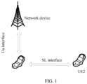
- FIG. 1 is a communication network architecture for sidelink communication provided by the present application.
- the communication network architecture includes at least two sidelink communication terminals UE1 and UE2, and a network device.
- the sidelink communication terminal UE1 may be used as a transmitting terminal in sidelink communication
- the sidelink communication terminal UE2 may be used as a receiving terminal in sidelink communication.
- the sidelink communication terminal in FIG. 1 which is also referred to as a terminal device, may refer to a device that provides voice and/or data connectivity to users, a handheld device with a wireless connection function, or other processing devices connected to a wireless modem, etc.
- the name of the terminal device may be different.
- the terminal device may be called user equipment (User Equipment, UE).
- a wireless terminal may communicate with one or more core networks (Core Networks, CNs) via a radio access network (Radio Access Network, RAN).
- the wireless terminal device may be a mobile terminal device such as a mobile phone (or called a "cellular" phone), and a computer with a mobile terminal device, for example, a portable, pocket-sized, handheld, computer built-in, or vehicle-mounted mobile device, which exchanges language and/or data with the radio access network.
- a personal communications service Personal Communications Service, PCS
- PCS Personal Communications Service
- cordless phone a cordless phone
- Session Initiated Protocol SIP
- WLL Wireless Local Loop
- PDA Personal Digital Assistant
- the wireless terminal device may also be called a system, a subscriber unit (subscriber unit), a subscriber station (subscriber station), a mobile station (mobile station), a mobile (mobile), a remote station (remote station), an access point (access point), a remote terminal (remote terminal), an access terminal (access terminal), a user terminal (user terminal), a user agent (user agent), and a user device (user device), which are not limited in the embodiments of the present application.
- the network device in FIG. 1 may specifically include a base station.
- the base station may include a plurality of cells providing services to the terminal.
- the base station may also be called an access point, or a device in the access network that communicates with a wireless terminal device through one or more sectors over an air interface, or other names.
- the network device may be used to interchange a received air frame with an Internet protocol (Internet Protocol, IP) packet, and may act as a router between the wireless terminal and the rest of the access network, where the rest of the access network may include an Internet protocol (IP) communication network.
- IP Internet protocol
- a positioning server of the network device may also coordinate the management of attributes of the air interface.
- an SL interface is used for sidelink communication between the sidelink communication terminal UE1 and the sidelink communication terminal UE2, and a Uu interface is used for sidelink communication between the sidelink communication terminal UE1 and the base station of the network device.
- the SL interface and the Uu interface independently maintain their own DRX and/or DTX states respectively. Therefore, there may be a situation where DRX and/or DTX active time (Active time) of the Uu interface and that of the SL interface remain out of synchronization.
- a sidelink communication resource allocated by it may fall within DRX and/or DTX inactive time of the sidelink communication interface in a time domain position, resulting in that the sidelink communication terminal cannot use the resource allocated by the network, thereby leading to a resource waste.
- FIG. 2 is a schematic diagram of scheduling signalings for sidelink communication in the prior art provided by the present application.
- the block area in FIG. 2 shows a case of signaling interaction between respective nodes when a sidelink communication interface adopts a resource allocation mode scheduled by the network.
- UE1 sends a scheduling request (SR, Scheduling Request) corresponding to the SL interface to the base station through the Uu interface.
- SR Scheduling Request
- UE1 maintains, at the Uu interface, a time period from a time of sending the SR to a time of receiving a scheduling signaling from the network device at the DRX active time of the Uu interface (a time period corresponding to t shown in FIG. 2 ), and the network device also maintains the DRX active time of the Uu interface during the above time period to perform resource scheduling of the SL interface.
- a DRX and/or DTX active state of the SL interface is determined based on a DRX and/or DTX related timer.
- the SL interface may enter a silent period, resulting in an SL resource allocated by the base station falling within a DRX and/or DTX inactive time period of the SL interface, which may easily lead to a resource waste.
- buffer status reporting Buffer status reporting, BSR for short
- BSR buffer status reporting
- a similar problem may also occur: when the sidelink communication terminal UE1 sends a BSR to the network device, the Uu interface will be activated and enter the DRX and/or DTX active time, and the base station performs corresponding resource scheduling for the SL interface according to the received BSR; at that point, once the SL resource allocated by the base station falls within the DRX and/or DTX inactive time period of the SL interface, a resource waste will be caused.
- BSR buffer status reporting
- the inventor proposes a method for maintaining a DRX and/or DTX state of a sidelink communication interface, so that after a sidelink communication terminal sends an SR and/or BSR corresponding to a sidelink communication interface to a network device, the sidelink communication terminal maintains DRX and/or DTX active time at the sidelink communication interface within a certain time period.
- a sidelink communication resource allocated by a network is always within the active time of the sidelink communication interface, for avoiding the sidelink communication interface resource scheduled by the network device falling within the DRX and/or DTX inactive time period of the sidelink communication interface in the time domain position, thereby the waste of the sidelink communication interface resource can be avoided.
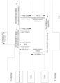
- FIG. 3 is a signaling diagram of a method for maintaining a DRX and/or DTX state of a sidelink communication interface provided by the present application. As shown in FIG. 3 , the method includes:
- the sidelink communication transmitting terminal UE1 and the sidelink communication receiving terminal UE2 perform sidelink communication through the sidelink communication interface SL interface, and the sidelink communication transmitting terminal UE1 performs cellular communication with the network device through the Uu interface.
- step 101 and step 103 is not limited. That is, as shown in FIG. 3 , it is possible to first execute step 101 and then execute step 103 (the execution sequence shown in FIG. 3 ); it is also possible to first execute step 103 and then execute step 101 (not shown in FIG. 3 ); and step 101 and step 103 may also be executed synchronously (not shown in FIG. 3 ).
- step 102 and step 103 although FIG. 3 shows the sequence between step 102 and step 103 (step 102 is executed first and then step 103 is executed), in the actual communication process, there is no correlation between the execution timings of step 102 and the execution sequence of step 103, and the sequence of step 102 and step 103 shown in FIG. 3 does not constitute any limitation to this technical solution.
- the network device after the network device receives the SR and/or BSR corresponding to the sidelink communication interface initiated by the sidelink communication transmitting terminal UE1 to the network device, its Uu interface will remain within the DRX and/or DTX active time, and at that point, the network device will issue the scheduling signaling corresponding to the sidelink communication interface to the sidelink communication terminal UE1 through the Uu interface.
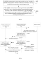
- FIG. 4 is a schematic flow diagram of a method for maintaining a DRX and/or DTX state of a sidelink communication interface provided by the present application, where an execution entity of a procedure of FIG. 4 is a sidelink communication transmitting terminal.
- the sidelink communication transmitting terminal UE1 may send a scheduling request (Scheduling Request, SR for short) and/or a buffer status reporting (Buffer status report, BSR for short) corresponding to the sidelink communication interface SL interface to the network device.
- a trigger condition for sending the SR and the BSR by the sidelink communication transmitting terminal UE1 may be specifically based on an existing specification, and this implementation does not impose any limitation on the trigger condition.
- step 102 after the sidelink communication transmitting terminal UE1 sends the SR and/or the BSR corresponding to the sidelink communication interface SL interface to the network device, the sidelink communication transmitting terminal UE1 updates the DRX and/or DTX active time of the sidelink communication interface, so that the sidelink communication transmitting terminal UE1 is in the DRX and/or DTX active time at the sidelink communication interface within a first preset time period.
- a start time of the first preset time period is a sending time of the SR or the BSR; an end time of the first preset time period is a receiving time at which the sidelink communication transmitting terminal UE1 receives the scheduling signaling corresponding to the sidelink communication interface sent by the network device or a time at which the sidelink communication transmitting terminal UE1 sends sidelink communication interface control information SCI to the sidelink communication receiving terminal UE2 through the sidelink communication interface.
- the sidelink communication transmitting terminal UE1 needs to remain the DRX and/or DTX active time at the sidelink communication interface during the first preset time period.
- the first preset time period may specifically be one of the following time periods:
- the sidelink communication interface control information SCI sent by the sidelink communication transmitting terminal to the sidelink communication receiving terminal through the sidelink communication interface may be SCI of a second stage.
- the sidelink communication interface SCI includes two parts, where first stage SCI (stage-1 SCI) is used to transmit indication information of a time/frequency domain resource, and second stage SCI (stage-2 SCI) is used to carry a sidelink communication source identification, a destination identification and other information.
- the sidelink communication transmitting terminal UE1 updates an active state of DRX and/or DTX of the sidelink communication interface, one of the following manners may be adopted specifically.
- One is to start a first timer at a same time or after the sidelink communication transmitting terminal UE1 sends the SR or BSR corresponding to the sidelink communication interface to the network device, so that the sidelink communication transmitting terminal UE1 is in the DRX and/or DTX active time at the sidelink communication interface during running of the first timer.
- the time length of the first timer may be configured by a network, or specified through a specification.
- the above first timer is a DRX and/or DTX inactivation timer for the sidelink communication interface.
- the second is to specify in a specification that a time period between a time at which the sidelink communication transmitting terminal sends the SR and/or BSR corresponding to the sidelink communication interface to the network device and a time at which the sidelink communication transmitting terminal receives the scheduling signaling corresponding to the sidelink communication interface from the network device is the DRX and /or DTX active time of the sidelink communication interface.
- step 103 in order to ensure that the sidelink communication receiving terminal UE2 also remains the DRX/DRX active time (i.e., UE2 ensures the DRX/DRX active time at the sidelink communication interface before step 106) at the sidelink communication interface before receiving the sidelink communication interface scheduling signaling SCI corresponding to the sidelink communication interface sent by the sidelink communication transmitting terminal UE1, the sidelink communication transmitting terminal UE1 will also send the indication information to the sidelink communication receiving terminal UE2, where the indication information will be used to indicate the sidelink communication receiving terminal UE2 to maintain the DRX and/or DTX active time in a second preset time period.
- the sidelink communication transmitting terminal UE1 sends the indication information to the sidelink communication receiving terminal UE2 through the sidelink communication interface, so that the sidelink communication receiving terminal UE2 updates the DRX and/or DTX active time of the sidelink communication interface according to the indication information, so that the sidelink communication receiving terminal UE2 is in the DRX and/or DTX active time at the sidelink communication interface within the second preset time period; where the second preset time period includes at least the time at which the sidelink communication receiving terminal UE2 receives, through the sidelink communication interface, the sidelink communication interface control information SCI sent by the sidelink communication transmitting terminal UE1.
- the time at which the sidelink communication transmitting terminal UE1 sends the indication information to the sidelink communication receiving terminal UE2 in step 103 being time T as an example: the above time T (the time at which the sidelink communication transmitting terminal UE1 sends the indication information to the sidelink communication interface to the sidelink communication receiving terminal UE2) may be one of the following times.
- a difference value between the time at which the sidelink communication transmitting terminal sends the indication information to the sidelink communication receiving terminal through the sidelink communication interface and the sending time at which the sidelink communication transmitting terminal sends the scheduling request SR or the buffer status reporting BSR is smaller than a first time threshold.
- the time T at which the sidelink communication transmitting terminal sends the indication information to the sidelink communication receiving terminal through the sidelink communication interface is after the sending time at which the sidelink communication transmitting terminal sends the scheduling request SR or the buffer status reporting BSR.
- a difference value between the time at which the sidelink communication transmitting terminal sends the indication information to the sidelink communication receiving terminal through the sidelink communication interface and the sending time at which the sidelink communication transmitting terminal sends the scheduling request SR or the buffer status reporting BSR is smaller than a second time threshold.
- this implementation does not limit the magnitude relationship between the two, and their respective specific values may be determined according to actual conditions.
- the indication information in step 103 is sent by the sidelink communication transmitting terminal UE1 to the sidelink communication receiving terminal UE2 through a physical layer signaling or a high-layer signaling.
- the indication information is sent by the sidelink communication transmitting terminal to the sidelink communication receiving terminal through the physical layer signaling
- the indication information is sent through the sidelink communication interface control information SCI, where the SCI does not include scheduling information of the sidelink communication resource, and is only used to prolong the time when the sidelink communication receiving terminal is in the DRX and/or DTX active time at the sidelink communication interface.
- the indication information may be specifically sent based on a MAC CE or RRC signaling of the high-layer signaling.
- the high-layer signaling may be a newly introduced signaling, or may also be an existing signaling with an IE being added, which is not limited in the present application.
- the indication information is sent by the sidelink communication transmitting terminal when the sidelink communication interface is in the DRX and/or DTX active time.
- a trigger condition for sending the indication information is that the sidelink communication transmitting terminal predicts that the sidelink communication receiving terminal will enter a DRX and/or DTX silent period before receiving the SCI.
- Whether the sidelink communication receiving terminal UE2 enters the DRX and/or DTX silent period may be determined by a state of running of a timer related to DRX and/or DTX of the sidelink communication interface of the sidelink communication receiving terminal UE2. For example, when the related timer is in a non-running state, the sidelink communication receiving terminal UE2 is in the DRX and/or DTX silent period of the sidelink communication interface.
- FIG. 5 is a schematic flow diagram of another method for maintaining a DRX and/or DTX state of a sidelink communication interface provided by the present application, where an execution entity of a procedure in FIG. 5 is a sidelink communication receiving terminal.
- the sidelink communication receiving terminal UE2 updates the DRX and/or DTX active time of the sidelink communication interface, so that the sidelink communication receiving terminal UE2 is in the DRX and/or DTX active time at the sidelink communication interface within the second preset time period.
- the second preset time period includes at least the time at which the sidelink communication receiving terminal UE2 receives, through the sidelink communication interface, the sidelink communication interface control information SCI sent by the sidelink communication transmitting terminal UE1.
- the sidelink communication interface control information SCI that is sent by the sidelink communication transmitting terminal and received by the sidelink communication receiving terminal through the sidelink communication interface is SCI of a second stage.
- the current sidelink communication interface SCI includes two parts, where a first stage SCI (stage-1 SCI) is used to transmit indication information of a time/frequency domain resource, and a second stage SCI (stage-2 SCI) is used to carry a sidelink communication source identification, a destination identification and other information.
- one of the following manners may be adopted specifically.
- One is to start a third timer at a same time or after the sidelink communication receiving terminal UE2 receives the indication information, so that the sidelink communication receiving terminal UE2 is in the DRX and/or DTX active time at the sidelink communication interface during running of the third timer.
- the time length of the third timer may be configured by the network or specified through a specification.
- the above third timer is a DRX and/or DTX inactivation timer for the sidelink communication interface.
- the second is to specify in a specification that a time period between a time at which the sidelink communication receiving terminal receives the indication information and a time at which the sidelink communication receiving terminal receives the scheduling signaling corresponding to the sidelink communication interface sent by the sidelink communication transmitting terminal is the DRX and/or DTX active time of the sidelink communication interface.
- the sidelink communication interface will be in the DRX and/or DTX active time.
- the sidelink communication transmitting terminal UE1 receives, at the Uu interface, the scheduling signaling corresponding to the sidelink communication interface sent by the network device. Then the sidelink communication transmitting terminal UE1 sends the scheduling signaling corresponding to the sidelink communication interface to the sidelink communication receiving terminal UE2 based on the scheduling signaling.
- the scheduling signaling corresponding to the sidelink communication interface that is sent by the sidelink communication transmitting terminal UE1 to the sidelink communication receiving terminal UE2 is specifically based on the SCI, and the content of the SCI is determined based on the scheduling signaling that is initiated by the network device and received by the sidelink communication transmitting terminal UE1.
- the above Embodiment 1 provides a method for maintaining a DRX and/or DTX state of a sidelink communication interface.
- the sidelink communication transmitting terminal can communicate with the sidelink communication receiving terminal through the sidelink communication interface that is in the DRX and/or DTX active time, when the sidelink communication transmitting terminal receives the resource issued by the network device, which avoids the source for the sidelink communication interface scheduled by the network device falling within the DRX and/or DTX inactive time period of the sidelink communication interface in the time domain position, thereby a waste of the resource for the sidelink communication interface can be avoided.
- FIG. 6 is a signaling diagram of another method for maintaining a DRX and/or DTX state of a sidelink communication interface provided by the present application. As shown in FIG. 6 , the method includes:
- the sidelink communication transmitting terminal UE1 and the sidelink communication receiving terminal UE2 perform sidelink communication through the sidelink communication interface SL interface, and the sidelink communication transmitting terminal UE1 performs cellular communication with the network device through the Uu interface.
- step 201 and step 203 in FIG. 6 the sequential order of execution of the steps may be that step 201 is executed first, and then step 203 is executed (as shown in FIG. 6 ); or that step 203 is executed first, and then step 201 is executed (not shown in FIG. 6 ); or that step 201 and step 203 are executed synchronously (not shown in FIG. 6 ).
- step 202 and step 203 although FIG. 6 shows the sequence between step 202 and step 203 (step 202 is executed first, and then step 203 is executed), in the actual communication process, there is no correlation between the execution timings of step 202 and step 203, and the sequence of step 202 and step 203 shown in FIG. 6 does not impose any limitation on this technical solution.
- steps 201, 202, 203, 205, 206 and 207 are similar to steps 101, 102, 103, 104, 105 and 106 in Embodiment 1, which will not be repeated in this embodiment.
- step 204 of this embodiment not only does the sidelink communication transmitting terminal UE1 update the DRX and/or DTX active time of the sidelink communication interface after sending the SR or the BSR corresponding to the sidelink communication interface to the network device, so that the sidelink communication transmitting terminal UE1 is in the DRX and/or DTX active time at the sidelink communication interface within the first preset time period and updates the DRX and/or DTX active time of the sidelink communication interface, but also the sidelink communication transmitting terminal UE1 sends the indication information to the sidelink communication receiving terminal UE2, and updates the DRX and/or DTX active time of the sidelink communication interface according to the indication information.
- FIG. 7 is a schematic flow diagram of a method for maintaining a DRX and/or DTX state of a sidelink communication interface provided by the present application, where an execution entity of a procedure of FIG. 7 is a sidelink communication transmitting terminal.
- the sidelink communication transmitting terminal UE1 sends the indication information to the sidelink communication receiving terminal UE2 through the sidelink communication interface, and the sidelink communication transmitting terminal UE1 updates the DRX and/or DTX active time of the sidelink communication interface, so that the sidelink communication transmitting terminal UE1 is in the DRX and/or DTX active time at the sidelink communication interface within the first preset time period.
- the first preset time period is similar to that described in the above Embodiment 1, that is, the start time of the first preset time period is the sending time of the SR or the BSR; the end time of the first preset time period is the receiving time at which the sidelink communication transmitting terminal receives the scheduling signaling corresponding to the sidelink communication interface sent by the network device or the time at which the sidelink communication transmitting terminal sends the sidelink communication interface control information SCI to the sidelink communication receiving terminal through the sidelink communication interface.
- the specific manner may include one of the following.
- One is to start a second timer at a same time or after the sidelink communication transmitting terminal UE1 sends the indication information, so that the sidelink communication transmitting terminal is in the DRX and/or DTX active time at the sidelink communication interface during running of the second timer.
- the time length of the second timer may be configured by the network, or specified through a specification.
- the second timer is a DRX and/or DTX inactivation timer for the sidelink communication interface.
- the second is to specify in a specification that a time period between a time at which the sidelink communication transmitting terminal sends the indication information to the sidelink communication receiving terminal and a time at which the sidelink communication transmitting terminal sends the SCI to the sidelink communication receiving terminal is the DRX and/or DTX active time of the sidelink communication interface.
- the above Embodiment 2 provides a method for maintaining a DRX and/or DTX state of a sidelink communication interface.
- the sidelink communication transmitting terminal can communicate with the sidelink communication receiving terminal through the sidelink communication interface that is in the DRX and/or DTX active time, when the sidelink communication transmitting terminal receives the resource issued by the network device, which avoids the source for the sidelink communication interface scheduled by the network device falling within the DRX and/or DTX inactive time period of the sidelink communication interface in the time domain position, thereby a waste of the resource for the sidelink communication interface can be avoided.
- FIG. 8 is a schematic structural diagram of a sidelink communication transmitting terminal provided by the present application.
- the sidelink communication transmitting terminal includes: including a memory 820, a transceiver 800 and a processor 810:
- the processor 810 is specifically configured to: start a first timer at a same time or after the sidelink communication transmitting terminal sends the SR or the BSR corresponding to the sidelink communication interface to the network device, so that the sidelink communication transmitting terminal is in the DRX and/or DTX active time at the sidelink communication interface during running of the first timer.
- the first timer is a DRX and/or DTX inactivation timer for the sidelink communication interface.
- the processor 810 is specifically configured to: specify in a specification that a time period between a time at which the sidelink communication transmitting terminal sends the SR and/or the BSR corresponding to the sidelink communication interface to the network device and a time at which the sidelink communication transmitting terminal receives the scheduling signaling corresponding to the sidelink communication interface from the network device is the DRX and/or DTX active time of the sidelink communication interface.
- the sidelink communication interface control information SCI that is sent by the sidelink communication transmitting terminal to the sidelink communication receiving terminal through the sidelink communication interface is SCI of a second stage.
- processor 810 is further configured to:
- a time at which the sidelink communication transmitting terminal sends the indication information to the sidelink communication receiving terminal through the sidelink communication interface is the sending time at which the sidelink communication transmitting terminal sends the scheduling request SR or the buffer status reporting BSR.
- the time at which the sidelink communication transmitting terminal sends the indication information to the sidelink communication receiving terminal through the sidelink communication interface is before the sending time at which the sidelink communication transmitting terminal sends the scheduling request SR or the buffer status reporting BSR.
- a difference value between the time at which the sidelink communication transmitting terminal sends the indication information to the sidelink communication receiving terminal through the sidelink communication interface and the sending time at which the sidelink communication transmitting terminal sends the scheduling request SR or the buffer status reporting BSR is smaller than a first time threshold.
- the time at which the sidelink communication transmitting terminal sends the indication information to the sidelink communication receiving terminal through the sidelink communication interface is after the sending time at which the sidelink communication transmitting terminal sends the scheduling request SR or the buffer status reporting BSR.
- the difference value between the time at which the sidelink communication transmitting terminal sends the indication information to the sidelink communication receiving terminal through the sidelink communication interface and the sending time at which the sidelink communication transmitting terminal sends the scheduling request SR or the buffer status reporting BSR is smaller than a second time threshold.
- the indication information is sent by the sidelink communication transmitting terminal to the sidelink communication receiving terminal through a physical layer signaling or a high-layer signaling.
- the indication information is sent through the sidelink communication interface control information SCI, where the SCI does not include scheduling information for a sidelink communication resource, and is only used to prolong time when the sidelink communication receiving terminal is in the DRX and/or DTX active time at the sidelink communication interface.
- the indication information is sent by the sidelink communication transmitting terminal at the DRX and/or DTX active time in which the sidelink communication interface is.
- a trigger condition for sending the indication information is that the sidelink communication transmitting terminal predicts that the sidelink communication receiving terminal will enter a DRX and/or DTX silent period before receiving the SCI.
- the processor 810 is further configured to: after the sidelink communication transmitting terminal sends the indication information to the sidelink communication receiving terminal, update the DRX and/or DTX active time of the sidelink communication interface, so that the sidelink communication transmitting terminal is in the DRX and/or DTX active time at the sidelink communication interface within the first preset time period.
- the processor 810 is specifically configured to: start a second timer at a same time or after sending the indication information, so that the sidelink communication transmitting terminal is in the DRX and/or DTX active time at the sidelink communication interface during running of the second timer.
- the second timer is a DRX and/or DTX inactivation timer for the sidelink communication interface.
- the processor 810 is specifically configured to: specify in a specification that a time period between a time at which the sidelink communication transmitting terminal sends the indication information to the sidelink communication receiving terminal and a time at which the sidelink communication transmitting terminal sends the SCI to the sidelink communication receiving terminal is the DRX and/or DTX active time of the sidelink communication interface.
- a bus architecture may include any number of interconnected buses and bridges, specifically, various circuits of one or more processors represented by the processor 810 and the memory represented by the memory 820 are linked together.
- the bus architecture may also link together various other circuits such as peripherals, voltage regulators and power management circuits, which are well known in the art and therefore will not be further described herein.
- a bus interface provides an interface.
- the transceiver 800 may be a plurality of elements, i.e., including a transmitter and a receiver, providing units for communicating with various other apparatuses over transmission media including wireless channels, wired channels, fiber optic cables, etc.
- a user interface may also be an interface capable of connecting externally and internally to required devices, and the connected devices include but are not limited to a keypad, a display, a speaker, a microphone, a joystick, etc.
- the processor 810 is responsible for managing the bus architecture and general processing, and the memory 820 may store data used by the processor 800 when performing operations.
- the processor 810 may be a CPU (central processing unit), an ASIC (Application Specific Integrated Circuit, application specific integrated circuit), an FPGA (Field-Programmable Gate Array, field-programmable gate array) or a CPLD (Complex Programmable Logic Device, complex programmable logic device), and the processor may also adopt a multicore architecture.
- CPU central processing unit
- ASIC Application Specific Integrated Circuit
- FPGA Field-Programmable Gate Array, field-programmable gate array
- CPLD Complex Programmable Logic Device, complex programmable logic device
- the processor 810 is configured to execute any one of the methods provided by the embodiments of the present application according to the obtained executable instructions by calling the computer program stored in the memory.
- the processor and the memory may also be physically separated.
- FIG. 9 is a schematic structural diagram of another sidelink communication transmitting terminal provided by the present application, which, as shown in FIG. 9 , includes: including a memory 920, a transceiver 900 and a processor 910:
- the sidelink communication interface control information SCI that is sent by the sidelink communication transmitting terminal and received by the sidelink communication receiving terminal through the sidelink communication interface is SCI of a second stage.
- the current sidelink communication interface SCI includes two parts, where a first stage SCI (stage-1 SCI) is used to transmit indication information of a time/frequency domain resource, and a second stage SCI (stage-2 SCI) is used to carry a sidelink communication source identification, a destination identification and other information.
- the processor 910 is specifically configured to: start a third timer at a same time or after receiving the indication information, so that the sidelink communication receiving terminal is in the DRX and/or DTX active time at the sidelink communication interface during running of the third timer.
- the third timer is a DRX and/or DTX inactivation timer for the sidelink communication interface.
- the processor 910 is specifically configured to: specify in a specification that a time period between a time at which the sidelink communication receiving terminal receives the indication information and a time at which the sidelink communication receiving terminal receives a scheduling signaling corresponding to the sidelink communication interface sent by the sidelink communication transmitting terminal is the DRX and/or DTX active time of the sidelink communication interface.
- a bus architecture may include any number of interconnected buses and bridges, specifically, various circuits of one or more processors represented by the processor 910 and the memory represented by the memory 920 are linked together.
- the bus architecture may also link together various other circuits such as peripherals, voltage regulators and power management circuits, which are well known in the art and therefore will not be further described herein.
- a bus interface provides an interface.
- the transceiver 900 may be a plurality of elements, i.e., including a transmitter and a receiver, providing units for communicating with various other apparatuses over transmission media including wireless channels, wired channels, fiber optic cables, etc.
- a user interface may also be an interface capable of connecting externally and internally to required devices, and the connected devices include but are not limited to a keypad, a display, a speaker, a microphone, a joystick, etc.
- the processor 910 is responsible for managing the bus architecture and general processing, and the memory 920 may store data used by the processor 900 when performing operations.
- the processor 910 may be a CPU (central processing unit), an ASIC (Application Specific Integrated Circuit, application specific integrated circuit), an FPGA (Field-Programmable Gate Array, field-programmable gate array) or a CPLD (Complex Programmable Logic Device, complex programmable logic device), and the processor may also adopt a multicore architecture.
- CPU central processing unit
- ASIC Application Specific Integrated Circuit
- FPGA Field-Programmable Gate Array, field-programmable gate array
- CPLD Complex Programmable Logic Device, complex programmable logic device
- the processor 910 is configured to execute any one of the methods provided by the embodiments of the present application according to the obtained executable instructions by calling the computer program stored in the memory.
- the processor and the memory may also be physically separated.
- FIG. 10 is a schematic structural diagram of further sidelink communication transmitting terminal provided by the present application. As shown in FIG. 10 , the sidelink communication transmitting terminal includes:
- the updating unit 12 is specifically configured to:
- the first timer is a DRX and/or DTX inactivation timer for the sidelink communication interface.
- the updating unit 12 is specifically configured to: specify in a specification that a time period between a time at which the sidelink communication transmitting terminal sends the SR and/or the BSR corresponding to the sidelink communication interface to the network device and a time at which the sidelink communication transmitting terminal receives the scheduling signaling corresponding to the sidelink communication interface from the network device is the DRX and/or DTX active time of the sidelink communication interface.
- the transceiving unit 11 is further configured to send indication information to the sidelink communication receiving terminal through the sidelink communication interface, so that the sidelink communication receiving terminal updates the DRX and/or DTX active time of the sidelink communication interface according to the indication information, so that the sidelink communication receiving terminal is in the DRX and/or DTX active time at the sidelink communication interface within a second preset time period; where the second preset time period includes at least a time at which the sidelink communication receiving terminal receives, through the sidelink communication interface, the sidelink communication interface control information SCI sent by the sidelink communication transmitting terminal.
- the time at which the sidelink communication transmitting terminal sends the indication information to the sidelink communication receiving terminal through the sidelink communication interface is the sending time at which the sidelink communication transmitting terminal sends the scheduling request SR or the buffer status reporting BSR.
- the time at which the sidelink communication transmitting terminal sends the indication information to the sidelink communication receiving terminal through the sidelink communication interface is before the sending time at which the sidelink communication transmitting terminal sends the scheduling request SR or the buffer status reporting BSR.
- a difference value between the time at which the sidelink communication transmitting terminal sends the indication information to the sidelink communication receiving terminal through the sidelink communication interface and the sending time at which the sidelink communication transmitting terminal sends the scheduling request SR or the buffer status reporting BSR is smaller than a first time threshold.
- the time at which the sidelink communication transmitting terminal sends the indication information to the sidelink communication receiving terminal through the sidelink communication interface is after the sending time at which the sidelink communication transmitting terminal sends the scheduling request SR or the buffer status reporting BSR.
- a difference value between the time at which the sidelink communication transmitting terminal sends the indication information to the sidelink communication receiving terminal through the sidelink communication interface and the sending time at which the sidelink communication transmitting terminal sends the scheduling request SR or the buffer status reporting BSR is smaller than a second time threshold.
- the indication information is sent by the sidelink communication transmitting terminal to the sidelink communication receiving terminal through a physical layer signaling or a high-layer signaling.
- the transceiving unit 11 when the indication information is sent by the sidelink communication transmitting terminal to the sidelink communication receiving terminal through the physical layer signaling, the transceiving unit 11 is configured to: the indication information is sent through the sidelink communication interface control information SCI, where the SCI does not include scheduling information for a sidelink communication resource, and is only used to prolong time when the sidelink communication receiving terminal is in the DRX and/or DTX active time at the sidelink communication interface.
- the indication information is sent by the sidelink communication transmitting terminal at the DRX and/or DTX active time in which the sidelink communication interface is.
- a trigger condition for sending the indication information is that the sidelink communication transmitting terminal predicts that the sidelink communication receiving terminal will enter a DRX and/or DTX silent period before receiving the SCI.
- the transceiving unit 11 is further configured to: after the sidelink communication transmitting terminal sends the indication information to the sidelink communication receiving terminal, the updating unit 12 is configured to update the DRX and/or DTX active time of the sidelink communication interface, so that the sidelink communication transmitting terminal is in the DRX and/or DTX active time at the sidelink communication interface within the first preset time period.
- the updating unit 12 is configured to: start, by the sidelink communication transmitting terminal, a second timer at a same time or after sending the indication information, so that the sidelink communication transmitting terminal is in the DRX and/or DTX active time at the sidelink communication interface during running of the second timer.
- the second timer is a DRX and/or DTX inactivation timer for the sidelink communication interface.
- the updating unit 12 is configured to: specify in a specification that a time period between a time at which the sidelink communication transmitting terminal sends the indication information to the sidelink communication receiving terminal and a time at which the sidelink communication transmitting terminal sends the SCI to the sidelink communication receiving terminal is the DRX and/or DTX active time of the sidelink communication interface.
- the division of units in the embodiments of the present application is illustrative and is only a logical function division, and there may be other division manners in actual implementations.
- the functional units in the embodiments of the present application may be integrated in a single processing unit, or each unit may be physically present separately, or two or more units may be integrated in a single unit.
- the above integrated units may be implemented either in the form of hardware or in the form of software functional units.
- the integrated units may be stored in a processor-readable storage medium when implemented in the form of software function units and sold or used as an independent product. Based on such understanding, a technical solution of the present application in essence, or the part of the technical solution which makes a contribution to the prior art, or all or part of the technical solution may be embodied in the form of a software product.
- the computer software product is stored in a storage medium, including several instructions for causing a computer device (which may be a personal computer, a server, or a network device, etc.) or a processor (processor) to execute all or part of the steps of the methods in the various embodiments of the present application.
- the aforementioned storage medium includes various media that can store program codes, such as a U disk, a mobile hard disk, a read-only memory (Read-Only Memory, ROM), a random access memory (Random Access Memory, RAM), a magnetic disk or an optical disk.
- program codes such as a U disk, a mobile hard disk, a read-only memory (Read-Only Memory, ROM), a random access memory (Random Access Memory, RAM), a magnetic disk or an optical disk.
- FIG. 11 is a schematic structural diagram of yet a sidelink communication receiving terminal provided by the present application. As shown in FIG. 11 , the sidelink communication receiving terminal includes:
- the updating unit 22 is specifically configured to: start, by the sidelink communication receiving terminal, a third timer at a same time or after receiving the indication information, so that the sidelink communication receiving terminal is in the DRX and/or DTX active time at the sidelink communication interface during running of the third timer.
- the third timer is a DRX and/or DTX inactivation timer for the sidelink communication interface.
- the updating unit 22 is specifically configured to: specify in a specification that a time period between a time at which the sidelink communication receiving terminal receives the indication information and a time at which the sidelink communication receiving terminal receives a scheduling signaling corresponding to the sidelink communication interface sent by the sidelink communication transmitting terminal is the DRX and/or DTX active time of the sidelink communication interface.
- the division of units in the embodiments of the present application is illustrative and is only a logical function division, and there may be other division manners in actual implementations.
- the functional units in the embodiments of the present application may be integrated in a single processing unit, or each unit may be physically present separately, or two or more units may be integrated in a single unit.
- the above integrated units may be implemented either in the form of hardware or in the form of software functional units.
- the integrated units may be stored in a processor-readable storage medium when implemented in the form of software function units and sold or used as an independent product. Based on such understanding, a technical solution of the present application in essence, or the part of the technical solution which makes a contribution to the prior art, or all or part of the technical solution may be embodied in the form of a software product.
- the computer software product is stored in a storage medium, including several instructions for causing a computer device (which may be a personal computer, a server, or a network device, etc.) or a processor (processor) to execute all or part of the steps of the methods in the various embodiments of the present application.
- the aforementioned storage medium includes various media that can store program codes, such as a U disk, a mobile hard disk, a read-only memory (Read-Only Memory, ROM), a random access memory (Random Access Memory, RAM), a magnetic disk or an optical disk.
- program codes such as a U disk, a mobile hard disk, a read-only memory (Read-Only Memory, ROM), a random access memory (Random Access Memory, RAM), a magnetic disk or an optical disk.
- the present application also provides a processor-readable storage medium.
- the processor-readable storage medium stores a computer program, and the computer program is used to cause the processor to execute the method described in Embodiment 1 and claims.
- the processor-readable storage medium may be any available medium or data storage device that can be accessed by a processor, including but not limited to a magnetic storage (such as a floppy disk, a hard disk, a magnetic tape, a magneto-optical disk (MO), etc.), an optical storage (such as a CD, a DVD, a BD, an HVD, etc.), and a semiconductor storage (such as a ROM, an EPROM, an EEPROM, a non-volatile memory (NAND FLASH), a solid state disk (SSD)), etc.
- a magnetic storage such as a floppy disk, a hard disk, a magnetic tape, a magneto-optical disk (MO), etc.
- an optical storage such as a CD, a DVD, a BD, an HVD, etc.
- a semiconductor storage such as a ROM, an EPROM, an EEPROM, a non-volatile memory (NAND FLASH), a solid state disk (SSD)
- the present application provides a computer program product, including a computer program.
- the computer program is executed by a processor, the steps of the method described in Embodiment 1 described above are implemented.
- the embodiments of the present application may be provided as methods, systems, or computer program products. Accordingly, the present application may take the form of an entirely hardware embodiment, an entirely software embodiment or an embodiment combining software and hardware aspects. Also, the present application may take the form of a computer program product embodied on one or more computer-usable storage media (including but not limited to a disk storage and an optical storage, etc.) containing computer-usable program codes therein.
- a computer-usable storage media including but not limited to a disk storage and an optical storage, etc.
- These computer-executable instructions may be provided to a processor of a general-purpose computer, a special-purpose computer, an embedded processor, or other programmable data processing devices to produce a machine, such that an apparatus for implementing a function specified in one or more procedures of the flowcharts and/or one or more blocks of the block diagrams may be produced via the instructions executed by the processor of the computer or other programmable data processing devices.
- processor-executable instructions may also be stored in a processor-readable memory capable of directing a computer or other programmable data processing devices to operate in a specific manner, so that the instructions stored in the processor-readable memory produce a manufacturing product including an instruction apparatus, where the instruction apparatus implements the function specified in one or more procedures of the flow charts and/or one or more blocks of the block diagrams.
- processor-executable instructions may also be loaded onto a computer or other programmable data processing devices, so that a series of operational steps are performed on the computer or other programmable devices to produce computer-implemented processing. Therefore, the instructions executed on the computer or other programmable devices provide steps for implementing the functions specified in one or more procedures of the flowcharts and/or one or more blocks of the block diagrams.
Landscapes
- Engineering & Computer Science (AREA)
- Computer Networks & Wireless Communication (AREA)
- Signal Processing (AREA)
- Databases & Information Systems (AREA)
- Mobile Radio Communication Systems (AREA)
Abstract
Description
- The present application claims the priority to
Chinese patent application No. 202110336748.9, titled "METHOD FOR MAINTAINING DRX AND/OR DTX STATE OF SIDELINK COMMUNICATION INTERFACE, AND SIDELINK COMMUNICATION TERMINALS" and filed with the China National Intellectual Property Administration on March 29, 2021 - The present application relates to the field of communication technologies, and in particular to a method for maintaining a DRX and/or DTX state of a sidelink communication interface and sidelink communication terminals.
- Sidelink communication refers to a communication mode in which terminals that are close to each other communicate via a sidelink communication interface between the terminals. A sidelink communication link between two terminals is also referred to as a sidelink (Sidelink), and a sidelink communication interface between the two terminals is also referred to as a sidelink (Sidelink) interface. In addition, a terminal may also communicate with a network device, a corresponding communication link therebetween being referred to as a Uu link, and a corresponding interface therebetween being referred to as a Uu interface.
- In order to realize power saving of the sidelink communication interface, discontinuous reception (Discontinuous Reception, DRX for short) and discontinuous transmission (Discontinuous Transmission, DTX for short) mechanisms of the sidelink communication interface are introduced for the sidelink communication interface in existing mechanisms.
- However, the existing DRX and/or DTX mechanism of the sidelink communication interface cannot guarantee that DRX and/or DTX active time (Active time) of the Uu interface and that of the SL interface are always synchronized, resulting in that when a network device allocates a resource for a terminal, the allocated resource corresponds to the DRX and/or DTX inactive time of the sidelink communication interface, thereby leading to a resource waste of the sidelink communication interface.
- The present application provides a method for maintaining a DRX and/or DTX state of a sidelink communication interface and sidelink communication terminals, which are used to prevent a resource for a sidelink communication interface scheduled by a network device from falling within DRX and/or DTX inactive time of the sidelink communication interface in a time domain position, thereby a waste of the resource for the sidelink communication interface can be avoided.
- In a first aspect, the present application provides a method for maintaining a DRX and/or DTX state of a sidelink communication interface, including:
- after a sidelink communication transmitting terminal sends a scheduling request SR or a buffer status reporting BSR corresponding to a sidelink communication interface to a network device, updating, by the sidelink communication transmitting terminal, DRX and/or DTX active time of the sidelink communication interface, so that the sidelink communication transmitting terminal is in the DRX and/or DTX active time at the sidelink communication interface within a first preset time period;
- where a start time of the first preset time period is a sending time of the SR or the BSR;
- an end time of the first preset time period is a receiving time at which the sidelink communication transmitting terminal receives a scheduling signaling corresponding to the sidelink communication interface sent by the network device or a time at which the sidelink communication transmitting terminal sends sidelink communication interface control information SCI to a sidelink communication receiving terminal through the sidelink communication interface.
- In a second aspect, the present application provides a method for maintaining a DRX and/or DTX state of a sidelink communication interface, including:
- receiving, by a sidelink communication receiving terminal and through a sidelink communication interface, indication information sent by a sidelink communication transmitting terminal;
- updating, by the sidelink communication receiving terminal, DRX and/or DTX active time of the sidelink communication interface according to the indication information, so that the sidelink communication receiving terminal is in the DRX and/or DTX active time at the sidelink communication interface within a second preset time period;
- where the second preset time period includes at least a time at which the sidelink communication receiving terminal receives, through the sidelink communication interface, sidelink communication interface control information SCI sent by the sidelink communication transmitting terminal.
- In a third aspect, the present application provides a sidelink communication transmitting terminal, including a memory, a transceiver and a processor:
the memory is configured to store a computer program; the transceiver is configured to transmit and receive data under control of the processor; the processor is configured to read the computer program in the memory and execute the following operations: - after the sidelink communication transmitting terminal sends a scheduling request SR or a buffer status reporting BSR corresponding to a sidelink communication interface to a network device, updating DRX and/or DTX active time of the sidelink communication interface, so that the sidelink communication transmitting terminal is in the DRX and/or DTX active time at the sidelink communication interface within a first preset time period;
- where a start time of the first preset time period is a sending time of the SR or the BSR;
- an end time of the first preset time period is a receiving time at which the sidelink communication transmitting terminal receives a scheduling signaling corresponding to the sidelink communication interface sent by the network device or a time at which the sidelink communication transmitting terminal sends sidelink communication interface control information SCI to a sidelink communication receiving terminal through the sidelink communication interface.
- In a fourth aspect, the present application provides a sidelink communication transmitting terminal, including a memory, a transceiver and a processor:
the memory is configured to store a computer program; the transceiver is configured to transmit and receive data under control of the processor; the processor is configured to read the computer program in the memory and execute the following operations: - receiving, by a sidelink communication receiving terminal and through a sidelink communication interface, indication information sent by the sidelink communication transmitting terminal; updating DRX and/or DTX active time of the sidelink communication interface according to the indication information, so that the sidelink communication receiving terminal is in the DRX and/or DTX active time at the sidelink communication interface within a second preset time period;
- where the second preset time period includes at least a time at which the sidelink communication receiving terminal receives, through the sidelink communication interface, sidelink communication interface control information SCI sent by the sidelink communication transmitting terminal.
- In a fifth aspect, the present application provides a sidelink communication transmitting terminal, including:
- a transceiving unit, configured to send a scheduling request SR or a buffer status reporting BSR corresponding to a sidelink communication interface to a network device;
- an updating unit, configured to update DRX and/or DTX active time of the sidelink communication interface, so that the sidelink communication transmitting terminal is in the DRX and/or DTX active time at the sidelink communication interface within a first preset time period;
- where a start time of the first preset time period is a sending time of the SR or the BSR;
- an end time of the first preset time period is a receiving time at which the sidelink communication transmitting terminal receives a scheduling signaling corresponding to the sidelink communication interface sent by the network device or a time at which the sidelink communication transmitting terminal sends sidelink communication interface control information SCI to a sidelink communication receiving terminal through the sidelink communication interface.
- In a sixth aspect, the present application provides a sidelink communication receiving terminal, including:
- a transceiving unit, configured to receive, through a sidelink communication interface, indication information sent by a sidelink communication transmitting terminal;
- an updating unit, configured to update DRX and/or DTX active time of the sidelink communication interface according to the indication information, so that the sidelink communication receiving terminal is in the DRX and/or DTX active time at the sidelink communication interface within a second preset time period;
- where the second preset time period includes at least a time at which the sidelink communication receiving terminal receives, through the sidelink communication interface, sidelink communication interface control information SCI sent by the sidelink communication transmitting terminal.
- In a seventh aspect, the present application provides a processor-readable storage medium which stores a computer program therein, and the computer program is used to cause a processor to execute the method according to any one of the first aspect or the second aspect.
- In an eighth aspect, the present application provides a computer program product including a computer program, and when the computer program is executed by a processor, steps of the method according to any one of the first aspect or the second aspect are implemented.
- According to the method for maintaining a DRX and/or DTX state of a sidelink communication interface and the sidelink communication terminals provided by the present application, a sidelink communication transmitting terminal updates DRX and/or DTX active time of a sidelink communication interface after the sidelink communication transmitting terminal sends a scheduling request SR or a buffer status reporting BSR corresponding to the sidelink communication interface to a network device, so that the sidelink communication transmitting terminal is in the DRX and/or DTX active time at the sidelink communication interface within a first preset time period. By using the above method, it is ensured that a sidelink communication resource allocated by a network is always within the active time of the sidelink communication interface; and the transmitting terminal of the sidelink communication terminals is also enabled to communicate with the receiving terminal of the sidelink communication terminals through the sidelink communication interface that is in the DRX and/or DTX active time, when the transmitting terminal of the sidelink communication terminals receives the resource issued by the network device, thereby avoiding a resource waste.
- It should be understood that what is described in the SUMMARY section above is not intended to limit key or important features of embodiments of the present invention, nor is it intended to limit the scope of the present invention. Other features of the present invention will be easily understood through the following description.
- In order to describe the technical solutions in the present application or in the prior art more clearly, drawings that need to be used in the description of embodiments or prior art will be introduced briefly in the following. Obviously, the drawings described below are some embodiments of the present invention, and for those of ordinary skill in the art, other drawings can be obtained based on these drawings without paying creative efforts.
-
FIG. 1 is a communication network architecture for sidelink communication provided by the present application. -
FIG. 2 is a schematic diagram of scheduling signalings for sidelink communication in the prior art provided by the present application. -
FIG. 3 is a signaling diagram of a method for maintaining a DRX and/or DTX state of a sidelink communication interface provided by the present application. -
FIG. 4 is a schematic flow diagram of a method for maintaining a DRX and/or DTX state of a sidelink communication interface provided by the present application. -
FIG. 5 is a schematic flow diagram of another method for maintaining a DRX and/or DTX state of a sidelink communication interface provided by the present application. -
FIG. 6 is a signaling diagram of another method for maintaining a DRX and/or DTX state of a sidelink communication interface provided by the present application. -
FIG. 7 is a schematic flow diagram of a method for maintaining a DRX and/or DTX state of a sidelink communication interface provided by the present application. -
FIG. 8 is a schematic structural diagram of a sidelink communication transmitting terminal provided by the present application. -
FIG. 9 is a schematic structural diagram of another sidelink communication transmitting terminal provided by the present application. -
FIG. 10 is a schematic structural diagram of further sidelink communication transmitting terminal provided by the present application. -
FIG. 11 is a schematic structural diagram of yet a sidelink communication receiving terminal provided by the present application. - Exemplary embodiments of the present application are described below in conjunction with the drawings, including various details of the embodiments of the present application to facilitate understanding, which should be regarded as merely exemplary. Accordingly, those of ordinary skill in the art should realize that various changes and modifications can be made to the embodiments described herein without departing from the scope and spirit of the present application. Also, descriptions of well-known functions and structures are omitted in the following description for clarity and conciseness.
- It should be noted that the methods and the apparatuses corresponding thereto are based on the same application concept. Since the methods and the apparatuses solve the problem with similar principles, reference can be made to each other for the implementation of the apparatuses and the methods, and the repetition will not be repeated.
- The technical solutions provided by the embodiments of the present application may be applied to various wireless communication systems.
- For example, the applied system may be a global system of mobile communication (global system of mobile communication, GSM) system, a code division multiple access (code division multiple access, CDMA) system, a wideband code division multiple access (Wideband Code Division Multiple Access, WCDMA) general packet radio service (general packet radio service, GPRS) system, a long term evolution (long term evolution, LTE) system, an LTE frequency division duplex (frequency division duplex, FDD) system, an LTE time division duplex (time division duplex, TDD) system, a long term evolution advanced (long term evolution advanced, LTE-A) system, a universal mobile system (universal mobile telecommunication system, UMTS), a worldwide interoperability for microwave access (worldwide interoperability for microwave access, WiMAX) system, a 5G new radio (New Radio, NR) system, etc. These various systems include terminal devices and network devices. The systems may also include a core network portion such as an evolved packet system (Evloved Packet System, EPS), a 5G system (5GS), etc.
- In order to facilitate the introduction of the technical solutions of the present application, the technical background involved in the present application will first be briefly described.
- Sidelink communication refers to a terminal-to-terminal communication between terminals that are close to each other. A sidelink communication link between two terminals is also referred to as a sidelink (Sidelink), and a sidelink communication interface between the two terminals is also referred to as a sidelink (Sidelink) interface. In addition, a terminal may also communicate with a network device, a corresponding communication link therebetween being referred to as a Uu link, and a corresponding interface therebetween being referred to as a Uu interface. In order to realize power saving of the sidelink communication interface, DRX and DTX mechanisms of the sidelink communication interface are introduced for the sidelink communication interface in existing mechanisms.
- In order to clearly understand the technical solutions provided by the present application, a solution in the prior art is first introduced in detail.
-
FIG. 1 is a communication network architecture for sidelink communication provided by the present application. As shown inFIG. 1 , the communication network architecture includes at least two sidelink communication terminals UE1 and UE2, and a network device. The sidelink communication terminal UE1 may be used as a transmitting terminal in sidelink communication, and the sidelink communication terminal UE2 may be used as a receiving terminal in sidelink communication. - Also, the sidelink communication terminal in
FIG. 1 , which is also referred to as a terminal device, may refer to a device that provides voice and/or data connectivity to users, a handheld device with a wireless connection function, or other processing devices connected to a wireless modem, etc. - In different systems, the name of the terminal device may be different. For example, in a 5G system, the terminal device may be called user equipment (User Equipment, UE). A wireless terminal may communicate with one or more core networks (Core Networks, CNs) via a radio access network (Radio Access Network, RAN). The wireless terminal device may be a mobile terminal device such as a mobile phone (or called a "cellular" phone), and a computer with a mobile terminal device, for example, a portable, pocket-sized, handheld, computer built-in, or vehicle-mounted mobile device, which exchanges language and/or data with the radio access network.
- For example, a personal communications service (Personal Communications Service, PCS) phone, a cordless phone, a session initiated protocol (Session Initiated Protocol, SIP) phone, a wireless local loop (Wireless Local Loop, WLL) station, a personal digital assistant (Personal Digital Assistant, PDA) or other devices. The wireless terminal device may also be called a system, a subscriber unit (subscriber unit), a subscriber station (subscriber station), a mobile station (mobile station), a mobile (mobile), a remote station (remote station), an access point (access point), a remote terminal (remote terminal), an access terminal (access terminal), a user terminal (user terminal), a user agent (user agent), and a user device (user device), which are not limited in the embodiments of the present application.
- The network device in
FIG. 1 may specifically include a base station. The base station may include a plurality of cells providing services to the terminal. Depending on a specific application, the base station may also be called an access point, or a device in the access network that communicates with a wireless terminal device through one or more sectors over an air interface, or other names. The network device may be used to interchange a received air frame with an Internet protocol (Internet Protocol, IP) packet, and may act as a router between the wireless terminal and the rest of the access network, where the rest of the access network may include an Internet protocol (IP) communication network. A positioning server of the network device may also coordinate the management of attributes of the air interface. - As shown in
FIG. 1 , an SL interface is used for sidelink communication between the sidelink communication terminal UE1 and the sidelink communication terminal UE2, and a Uu interface is used for sidelink communication between the sidelink communication terminal UE1 and the base station of the network device. Generally, the SL interface and the Uu interface independently maintain their own DRX and/or DTX states respectively. Therefore, there may be a situation where DRX and/or DTX active time (Active time) of the Uu interface and that of the SL interface remain out of synchronization. This also makes it possible that when a network device performs scheduling for sidelink communication through the Uu interface, a sidelink communication resource allocated by it may fall within DRX and/or DTX inactive time of the sidelink communication interface in a time domain position, resulting in that the sidelink communication terminal cannot use the resource allocated by the network, thereby leading to a resource waste. - Specifically,
FIG. 2 is a schematic diagram of scheduling signalings for sidelink communication in the prior art provided by the present application. The block area inFIG. 2 shows a case of signaling interaction between respective nodes when a sidelink communication interface adopts a resource allocation mode scheduled by the network. First, when the sidelink communication transmitting terminal UE1 has a data transmission requirement at the SL interface, UE1 sends a scheduling request (SR, Scheduling Request) corresponding to the SL interface to the base station through the Uu interface. According to a Uu DRX active time maintenance rule, once UE1 sends the SR, UE1 maintains, at the Uu interface, a time period from a time of sending the SR to a time of receiving a scheduling signaling from the network device at the DRX active time of the Uu interface (a time period corresponding to t shown inFIG. 2 ), and the network device also maintains the DRX active time of the Uu interface during the above time period to perform resource scheduling of the SL interface. - For the SL interface, a DRX and/or DTX active state of the SL interface is determined based on a DRX and/or DTX related timer. When the Uu interface is maintained at the active time (active time) and resource scheduling for the SL interface is performed, the SL interface may enter a silent period, resulting in an SL resource allocated by the base station falling within a DRX and/or DTX inactive time period of the SL interface, which may easily lead to a resource waste.
- Furthermore, when the sidelink communication terminal UE1 performs buffer status reporting (Buffer status reporting, BSR for short) to the network device, a similar problem may also occur:
when the sidelink communication terminal UE1 sends a BSR to the network device, the Uu interface will be activated and enter the DRX and/or DTX active time, and the base station performs corresponding resource scheduling for the SL interface according to the received BSR; at that point, once the SL resource allocated by the base station falls within the DRX and/or DTX inactive time period of the SL interface, a resource waste will be caused. - In view of the problem mentioned above, the inventor proposes a method for maintaining a DRX and/or DTX state of a sidelink communication interface, so that after a sidelink communication terminal sends an SR and/or BSR corresponding to a sidelink communication interface to a network device, the sidelink communication terminal maintains DRX and/or DTX active time at the sidelink communication interface within a certain time period. In this way, it can be ensured that a sidelink communication resource allocated by a network is always within the active time of the sidelink communication interface, for avoiding the sidelink communication interface resource scheduled by the network device falling within the DRX and/or DTX inactive time period of the sidelink communication interface in the time domain position, thereby the waste of the sidelink communication interface resource can be avoided.
- The embodiments of the present application will be specifically described below with reference to the drawings.
-
FIG. 3 is a signaling diagram of a method for maintaining a DRX and/or DTX state of a sidelink communication interface provided by the present application. As shown inFIG. 3 , the method includes: -
step 101, a sidelink communication transmitting terminal sends an SR or a BSR corresponding to a sidelink communication interface to a network device; -
step 102, the sidelink communication transmitting terminal updates DRX and/or DTX active time of the sidelink communication interface; -
step 103, the sidelink communication transmitting terminal sends indication information to a sidelink communication receiving terminal; -
step 104, the sidelink communication receiving terminal updates the DRX and/or DTX active time of the sidelink communication interface according to the indication information; -
step 105, the sidelink communication transmitting terminal receives, at a Uu interface, a scheduling signaling corresponding to the sidelink communication interface sent by the network device; -
step 106, the sidelink communication transmitting terminal sends, at the sidelink communication interface, the scheduling signaling corresponding to the sidelink communication interface to the sidelink communication receiving terminal. - It should be noted that, in signalings shown in
FIG. 3 , the sidelink communication transmitting terminal UE1 and the sidelink communication receiving terminal UE2 perform sidelink communication through the sidelink communication interface SL interface, and the sidelink communication transmitting terminal UE1 performs cellular communication with the network device through the Uu interface. - In an actual communication process, the execution sequence of
step 101 and step 103 is not limited. That is, as shown inFIG. 3 , it is possible to first executestep 101 and then execute step 103 (the execution sequence shown inFIG. 3 ); it is also possible to first executestep 103 and then execute step 101 (not shown inFIG. 3 ); and step 101 and step 103 may also be executed synchronously (not shown inFIG. 3 ). - In addition, for
step 102 and step 103, althoughFIG. 3 shows the sequence betweenstep 102 and step 103 (step 102 is executed first and then step 103 is executed), in the actual communication process, there is no correlation between the execution timings ofstep 102 and the execution sequence ofstep 103, and the sequence ofstep 102 and step 103 shown inFIG. 3 does not constitute any limitation to this technical solution. - Specifically, in the communication process, after the network device receives the SR and/or BSR corresponding to the sidelink communication interface initiated by the sidelink communication transmitting terminal UE1 to the network device, its Uu interface will remain within the DRX and/or DTX active time, and at that point, the network device will issue the scheduling signaling corresponding to the sidelink communication interface to the sidelink communication terminal UE1 through the Uu interface.
-
FIG. 4 is a schematic flow diagram of a method for maintaining a DRX and/or DTX state of a sidelink communication interface provided by the present application, where an execution entity of a procedure ofFIG. 4 is a sidelink communication transmitting terminal. - According to
FIG. 3 in combination withFIG. 4 , based on network requirements, as shown instep 101, the sidelink communication transmitting terminal UE1 may send a scheduling request (Scheduling Request, SR for short) and/or a buffer status reporting (Buffer status report, BSR for short) corresponding to the sidelink communication interface SL interface to the network device. A trigger condition for sending the SR and the BSR by the sidelink communication transmitting terminal UE1 may be specifically based on an existing specification, and this implementation does not impose any limitation on the trigger condition. - As shown in
step 102, after the sidelink communication transmitting terminal UE1 sends the SR and/or the BSR corresponding to the sidelink communication interface SL interface to the network device, the sidelink communication transmitting terminal UE1 updates the DRX and/or DTX active time of the sidelink communication interface, so that the sidelink communication transmitting terminal UE1 is in the DRX and/or DTX active time at the sidelink communication interface within a first preset time period. - A start time of the first preset time period is a sending time of the SR or the BSR; an end time of the first preset time period is a receiving time at which the sidelink communication transmitting terminal UE1 receives the scheduling signaling corresponding to the sidelink communication interface sent by the network device or a time at which the sidelink communication transmitting terminal UE1 sends sidelink communication interface control information SCI to the sidelink communication receiving terminal UE2 through the sidelink communication interface.
- That is to say, as an optional implementation, the sidelink communication transmitting terminal UE1 needs to remain the DRX and/or DTX active time at the sidelink communication interface during the first preset time period. The first preset time period may specifically be one of the following time periods:
- (1) a time period from a time after the sidelink communication transmitting terminal UE1 sends the SR/BSR to a time before the sidelink communication transmitting terminal UE1 receives the scheduling signaling corresponding to the sidelink communication interface sent by the network device;
- (2) a time period from a time after the sidelink communication terminal UE1 sends the SR/BSR to a time before the sidelink communication transmitting terminal UE1 sends the sidelink communication interface control information SCI to the sidelink communication receiving terminal UE2 through the sidelink communication interface.
- Optionally, the sidelink communication interface control information SCI sent by the sidelink communication transmitting terminal to the sidelink communication receiving terminal through the sidelink communication interface may be SCI of a second stage. At present, the sidelink communication interface SCI includes two parts, where first stage SCI (stage-1 SCI) is used to transmit indication information of a time/frequency domain resource, and second stage SCI (stage-2 SCI) is used to carry a sidelink communication source identification, a destination identification and other information.
- As an optional implementation, when the sidelink communication transmitting terminal UE1 updates an active state of DRX and/or DTX of the sidelink communication interface, one of the following manners may be adopted specifically.
- One is to start a first timer at a same time or after the sidelink communication transmitting terminal UE1 sends the SR or BSR corresponding to the sidelink communication interface to the network device, so that the sidelink communication transmitting terminal UE1 is in the DRX and/or DTX active time at the sidelink communication interface during running of the first timer.
- The time length of the first timer may be configured by a network, or specified through a specification.
- Further, the above first timer is a DRX and/or DTX inactivation timer for the sidelink communication interface.
- The second is to specify in a specification that a time period between a time at which the sidelink communication transmitting terminal sends the SR and/or BSR corresponding to the sidelink communication interface to the network device and a time at which the sidelink communication transmitting terminal receives the scheduling signaling corresponding to the sidelink communication interface from the network device is the DRX and /or DTX active time of the sidelink communication interface.
- As shown in
step 103, in order to ensure that the sidelink communication receiving terminal UE2 also remains the DRX/DRX active time (i.e., UE2 ensures the DRX/DRX active time at the sidelink communication interface before step 106) at the sidelink communication interface before receiving the sidelink communication interface scheduling signaling SCI corresponding to the sidelink communication interface sent by the sidelink communication transmitting terminal UE1, the sidelink communication transmitting terminal UE1 will also send the indication information to the sidelink communication receiving terminal UE2, where the indication information will be used to indicate the sidelink communication receiving terminal UE2 to maintain the DRX and/or DTX active time in a second preset time period. - That is, the sidelink communication transmitting terminal UE1 sends the indication information to the sidelink communication receiving terminal UE2 through the sidelink communication interface, so that the sidelink communication receiving terminal UE2 updates the DRX and/or DTX active time of the sidelink communication interface according to the indication information, so that the sidelink communication receiving terminal UE2 is in the DRX and/or DTX active time at the sidelink communication interface within the second preset time period;
where the second preset time period includes at least the time at which the sidelink communication receiving terminal UE2 receives, through the sidelink communication interface, the sidelink communication interface control information SCI sent by the sidelink communication transmitting terminal UE1. - By taking the time at which the sidelink communication transmitting terminal UE1 sends the indication information to the sidelink communication receiving terminal UE2 in
step 103 being time T as an example:
the above time T (the time at which the sidelink communication transmitting terminal UE1 sends the indication information to the sidelink communication interface to the sidelink communication receiving terminal UE2) may be one of the following times. - (1) The time T at which the sidelink communication transmitting terminal sends the indication information to the sidelink communication receiving terminal through the sidelink communication interface is the sending time at which the sidelink communication transmitting terminal sends the scheduling request SR or the buffer status reporting BSR.
- (2) The time T at which the sidelink communication transmitting terminal sends the indication information to the sidelink communication receiving terminal through the sidelink communication interface is before the sending time at which the sidelink communication transmitting terminal sends the scheduling request SR or the buffer status reporting BSR.
- A difference value between the time at which the sidelink communication transmitting terminal sends the indication information to the sidelink communication receiving terminal through the sidelink communication interface and the sending time at which the sidelink communication transmitting terminal sends the scheduling request SR or the buffer status reporting BSR is smaller than a first time threshold.
- (3) The time T at which the sidelink communication transmitting terminal sends the indication information to the sidelink communication receiving terminal through the sidelink communication interface is after the sending time at which the sidelink communication transmitting terminal sends the scheduling request SR or the buffer status reporting BSR.
- A difference value between the time at which the sidelink communication transmitting terminal sends the indication information to the sidelink communication receiving terminal through the sidelink communication interface and the sending time at which the sidelink communication transmitting terminal sends the scheduling request SR or the buffer status reporting BSR is smaller than a second time threshold.
- For the first time threshold and the second time threshold described above, this implementation does not limit the magnitude relationship between the two, and their respective specific values may be determined according to actual conditions.
- As an optional implementation, the indication information in
step 103 is sent by the sidelink communication transmitting terminal UE1 to the sidelink communication receiving terminal UE2 through a physical layer signaling or a high-layer signaling. - When the indication information is sent by the sidelink communication transmitting terminal to the sidelink communication receiving terminal through the physical layer signaling, the indication information is sent through the sidelink communication interface control information SCI, where the SCI does not include scheduling information of the sidelink communication resource, and is only used to prolong the time when the sidelink communication receiving terminal is in the DRX and/or DTX active time at the sidelink communication interface.
- When the indication information is sent by the sidelink communication transmitting terminal to the sidelink communication receiving terminal through the high-layer signaling, the indication information may be specifically sent based on a MAC CE or RRC signaling of the high-layer signaling. In addition, the high-layer signaling may be a newly introduced signaling, or may also be an existing signaling with an IE being added, which is not limited in the present application.
- As an optional implementation, in order to ensure that the indication information can be effectively sent to the sidelink communication receiving terminal, the indication information is sent by the sidelink communication transmitting terminal when the sidelink communication interface is in the DRX and/or DTX active time.
- As an optional implementation, in order to save signaling overhead, a trigger condition for sending the indication information is that the sidelink communication transmitting terminal predicts that the sidelink communication receiving terminal will enter a DRX and/or DTX silent period before receiving the SCI.
- Whether the sidelink communication receiving terminal UE2 enters the DRX and/or DTX silent period may be determined by a state of running of a timer related to DRX and/or DTX of the sidelink communication interface of the sidelink communication receiving terminal UE2. For example, when the related timer is in a non-running state, the sidelink communication receiving terminal UE2 is in the DRX and/or DTX silent period of the sidelink communication interface.
-
FIG. 5 is a schematic flow diagram of another method for maintaining a DRX and/or DTX state of a sidelink communication interface provided by the present application, where an execution entity of a procedure inFIG. 5 is a sidelink communication receiving terminal. - With reference to
FIG. 3 in combination withFIG. 5 , after the sidelink communication transmitting terminal UE1 sends the indication information to the sidelink communication receiving terminal UE2, that is, after the sidelink communication receiving terminal UE2 receives the indication information sent by the sidelink communication transmitting terminal UE1, as shown instep 104, the sidelink communication receiving terminal UE2 updates the DRX and/or DTX active time of the sidelink communication interface, so that the sidelink communication receiving terminal UE2 is in the DRX and/or DTX active time at the sidelink communication interface within the second preset time period. The second preset time period includes at least the time at which the sidelink communication receiving terminal UE2 receives, through the sidelink communication interface, the sidelink communication interface control information SCI sent by the sidelink communication transmitting terminal UE1. - As an optional implementation, the sidelink communication interface control information SCI that is sent by the sidelink communication transmitting terminal and received by the sidelink communication receiving terminal through the sidelink communication interface is SCI of a second stage. Similar to the SCI in the foregoing implementations, the current sidelink communication interface SCI includes two parts, where a first stage SCI (stage-1 SCI) is used to transmit indication information of a time/frequency domain resource, and a second stage SCI (stage-2 SCI) is used to carry a sidelink communication source identification, a destination identification and other information.
- As an optional implementation, for updating the DRX and/or DTX active time of the sidelink communication interface according to the indication information by the sidelink communication receiving terminal UE2, one of the following manners may be adopted specifically.
- One is to start a third timer at a same time or after the sidelink communication receiving terminal UE2 receives the indication information, so that the sidelink communication receiving terminal UE2 is in the DRX and/or DTX active time at the sidelink communication interface during running of the third timer. The time length of the third timer may be configured by the network or specified through a specification.
- Further, the above third timer is a DRX and/or DTX inactivation timer for the sidelink communication interface.
- The second is to specify in a specification that a time period between a time at which the sidelink communication receiving terminal receives the indication information and a time at which the sidelink communication receiving terminal receives the scheduling signaling corresponding to the sidelink communication interface sent by the sidelink communication transmitting terminal is the DRX and/or DTX active time of the sidelink communication interface.
- Through
steps 101 to 104 described above, the sidelink communication interface will be in the DRX and/or DTX active time. At this time, as shown insteps - The scheduling signaling corresponding to the sidelink communication interface that is sent by the sidelink communication transmitting terminal UE1 to the sidelink communication receiving terminal UE2 is specifically based on the SCI, and the content of the SCI is determined based on the scheduling signaling that is initiated by the network device and received by the sidelink communication transmitting terminal UE1.
- The above Embodiment 1 provides a method for maintaining a DRX and/or DTX state of a sidelink communication interface. By updating the DRX and/or DTX active time of the sidelink communication interface by the sidelink communication transmitting terminal after the sidelink communication transmitting terminal sends the SR or the BSR corresponding to the sidelink communication interface to the network device, and updating the DRX and/or DTX active time of the sidelink communication interface by the sidelink communication receiving terminal, the sidelink communication transmitting terminal can communicate with the sidelink communication receiving terminal through the sidelink communication interface that is in the DRX and/or DTX active time, when the sidelink communication transmitting terminal receives the resource issued by the network device, which avoids the source for the sidelink communication interface scheduled by the network device falling within the DRX and/or DTX inactive time period of the sidelink communication interface in the time domain position, thereby a waste of the resource for the sidelink communication interface can be avoided.
- On the basis of Embodiment 1,
FIG. 6 is a signaling diagram of another method for maintaining a DRX and/or DTX state of a sidelink communication interface provided by the present application. As shown inFIG. 6 , the method includes: -
step 201, a sidelink communication transmitting terminal sends an SR or a BSR corresponding to a sidelink communication interface to a network device; -
step 202, the sidelink communication transmitting terminal updates DRX and/or DTX active time of the sidelink communication interface; -
step 203, the sidelink communication transmitting terminal sends indication information to a sidelink communication receiving terminal; -
step 204, the sidelink communication transmitting terminal updates the DRX and/or DTX active time of the sidelink communication interface according to the indication information; -
step 205, the sidelink communication receiving terminal receives the indication information and updates the DRX and/or DTX active time of the sidelink communication interface; -
step 206, the sidelink communication transmitting terminal receives, at a Uu interface, a scheduling signaling corresponding to the sidelink communication interface sent by the network device; -
step 207, the sidelink communication transmitting terminal sends, at the sidelink communication interface, the scheduling signaling corresponding to the sidelink communication interface to the sidelink communication receiving terminal. - It should be noted that similar to Embodiment 1, in signalings shown in
FIG. 6 , the sidelink communication transmitting terminal UE1 and the sidelink communication receiving terminal UE2 perform sidelink communication through the sidelink communication interface SL interface, and the sidelink communication transmitting terminal UE1 performs cellular communication with the network device through the Uu interface. - For
step 201 and step 203 inFIG. 6 , the sequential order of execution of the steps may be thatstep 201 is executed first, and then step 203 is executed (as shown inFIG. 6 ); or thatstep 203 is executed first, and then step 201 is executed (not shown inFIG. 6 ); or thatstep 201 and step 203 are executed synchronously (not shown inFIG. 6 ). - In addition, for
step 202 and step 203, althoughFIG. 6 shows the sequence betweenstep 202 and step 203 (step 202 is executed first, and then step 203 is executed), in the actual communication process, there is no correlation between the execution timings ofstep 202 and step 203, and the sequence ofstep 202 and step 203 shown inFIG. 6 does not impose any limitation on this technical solution. - In Embodiment 2,
steps steps - Different from Embodiment 1, in
step 204 of this embodiment, not only does the sidelink communication transmitting terminal UE1 update the DRX and/or DTX active time of the sidelink communication interface after sending the SR or the BSR corresponding to the sidelink communication interface to the network device, so that the sidelink communication transmitting terminal UE1 is in the DRX and/or DTX active time at the sidelink communication interface within the first preset time period and updates the DRX and/or DTX active time of the sidelink communication interface, but also the sidelink communication transmitting terminal UE1 sends the indication information to the sidelink communication receiving terminal UE2, and updates the DRX and/or DTX active time of the sidelink communication interface according to the indication information. -
FIG. 7 is a schematic flow diagram of a method for maintaining a DRX and/or DTX state of a sidelink communication interface provided by the present application, where an execution entity of a procedure ofFIG. 7 is a sidelink communication transmitting terminal. - As shown in
FIG. 6 in combination withFIG. 7 , the sidelink communication transmitting terminal UE1 sends the indication information to the sidelink communication receiving terminal UE2 through the sidelink communication interface, and the sidelink communication transmitting terminal UE1 updates the DRX and/or DTX active time of the sidelink communication interface, so that the sidelink communication transmitting terminal UE1 is in the DRX and/or DTX active time at the sidelink communication interface within the first preset time period. - The first preset time period is similar to that described in the above Embodiment 1, that is, the start time of the first preset time period is the sending time of the SR or the BSR; the end time of the first preset time period is the receiving time at which the sidelink communication transmitting terminal receives the scheduling signaling corresponding to the sidelink communication interface sent by the network device or the time at which the sidelink communication transmitting terminal sends the sidelink communication interface control information SCI to the sidelink communication receiving terminal through the sidelink communication interface.
- In an optional implementation, after the sidelink communication transmitting terminal UE1 sends the indication information to the sidelink communication receiving terminal UE2, for updating the DRX and/or DTX active time of the sidelink communication interface by the sidelink communication transmitting terminal UE1, the specific manner may include one of the following.
- One is to start a second timer at a same time or after the sidelink communication transmitting terminal UE1 sends the indication information, so that the sidelink communication transmitting terminal is in the DRX and/or DTX active time at the sidelink communication interface during running of the second timer. The time length of the second timer may be configured by the network, or specified through a specification.
- In a further optional implementation, the second timer is a DRX and/or DTX inactivation timer for the sidelink communication interface.
- The second is to specify in a specification that a time period between a time at which the sidelink communication transmitting terminal sends the indication information to the sidelink communication receiving terminal and a time at which the sidelink communication transmitting terminal sends the SCI to the sidelink communication receiving terminal is the DRX and/or DTX active time of the sidelink communication interface.
- The above Embodiment 2 provides a method for maintaining a DRX and/or DTX state of a sidelink communication interface. By updating the DRX and/or DTX active time of the sidelink communication interface by the sidelink communication transmitting terminal after the sidelink communication transmitting terminal sends the SR or the BSR corresponding to the sidelink communication interface to the network device, and updating the DRX and/or DTX active time of the sidelink communication interface by the sidelink communication receiving terminal, the sidelink communication transmitting terminal can communicate with the sidelink communication receiving terminal through the sidelink communication interface that is in the DRX and/or DTX active time, when the sidelink communication transmitting terminal receives the resource issued by the network device, which avoids the source for the sidelink communication interface scheduled by the network device falling within the DRX and/or DTX inactive time period of the sidelink communication interface in the time domain position, thereby a waste of the resource for the sidelink communication interface can be avoided.
-
FIG. 8 is a schematic structural diagram of a sidelink communication transmitting terminal provided by the present application. As shown inFIG. 8 , the sidelink communication transmitting terminal includes:
including amemory 820, atransceiver 800 and a processor 810: - the
memory 820 is configured to store a computer program; - the
transceiver 800 is configured to transmit and receive data under control of theprocessor 810; - the
processor 810 is configured to read the computer program in thememory 820 and perform the following operations:- after the sidelink communication transmitting terminal sends a scheduling request SR or a buffer status reporting BSR corresponding to a sidelink communication interface to a network device, updating DRX and/or DTX active time of the sidelink communication interface, so that the sidelink communication transmitting terminal is in the DRX and/or DTX active time at the sidelink communication interface within a first preset time period;
- where a start time of the first preset time period is a sending time of the SR or the BSR;
- an end time of the first preset time period is a receiving time at which the sidelink communication transmitting terminal receives a scheduling signaling corresponding to the sidelink communication interface sent by the network device or a time at which the sidelink communication transmitting terminal sends sidelink communication interface control information SCI to a sidelink communication receiving terminal through the sidelink communication interface.
- Optionally, the
processor 810 is specifically configured to:
start a first timer at a same time or after the sidelink communication transmitting terminal sends the SR or the BSR corresponding to the sidelink communication interface to the network device, so that the sidelink communication transmitting terminal is in the DRX and/or DTX active time at the sidelink communication interface during running of the first timer. - Optionally, the first timer is a DRX and/or DTX inactivation timer for the sidelink communication interface.
- Optionally, the
processor 810 is specifically configured to:
specify in a specification that a time period between a time at which the sidelink communication transmitting terminal sends the SR and/or the BSR corresponding to the sidelink communication interface to the network device and a time at which the sidelink communication transmitting terminal receives the scheduling signaling corresponding to the sidelink communication interface from the network device is the DRX and/or DTX active time of the sidelink communication interface. - Optionally, the sidelink communication interface control information SCI that is sent by the sidelink communication transmitting terminal to the sidelink communication receiving terminal through the sidelink communication interface is SCI of a second stage.
- Optionally, the
processor 810 is further configured to: - send, by the sidelink communication transmitting terminal, indication information to the sidelink communication receiving terminal through the sidelink communication interface, so that the sidelink communication receiving terminal updates the DRX and/or DTX active time of the sidelink communication interface according to the indication information, so that the sidelink communication receiving terminal is in the DRX and/or DTX active time at the sidelink communication interface within a second preset time period;
- where the second preset time period includes at least a time at which the sidelink communication receiving terminal receives, through the sidelink communication interface, the sidelink communication interface control information SCI sent by the sidelink communication transmitting terminal.
- Optionally, a time at which the sidelink communication transmitting terminal sends the indication information to the sidelink communication receiving terminal through the sidelink communication interface is the sending time at which the sidelink communication transmitting terminal sends the scheduling request SR or the buffer status reporting BSR.
- Optionally, the time at which the sidelink communication transmitting terminal sends the indication information to the sidelink communication receiving terminal through the sidelink communication interface is before the sending time at which the sidelink communication transmitting terminal sends the scheduling request SR or the buffer status reporting BSR.
- Optionally, a difference value between the time at which the sidelink communication transmitting terminal sends the indication information to the sidelink communication receiving terminal through the sidelink communication interface and the sending time at which the sidelink communication transmitting terminal sends the scheduling request SR or the buffer status reporting BSR is smaller than a first time threshold.
- Optionally, the time at which the sidelink communication transmitting terminal sends the indication information to the sidelink communication receiving terminal through the sidelink communication interface is after the sending time at which the sidelink communication transmitting terminal sends the scheduling request SR or the buffer status reporting BSR.
- Optionally, the difference value between the time at which the sidelink communication transmitting terminal sends the indication information to the sidelink communication receiving terminal through the sidelink communication interface and the sending time at which the sidelink communication transmitting terminal sends the scheduling request SR or the buffer status reporting BSR is smaller than a second time threshold.
- Optionally, the indication information is sent by the sidelink communication transmitting terminal to the sidelink communication receiving terminal through a physical layer signaling or a high-layer signaling.
- Optionally, the indication information is sent through the sidelink communication interface control information SCI, where the SCI does not include scheduling information for a sidelink communication resource, and is only used to prolong time when the sidelink communication receiving terminal is in the DRX and/or DTX active time at the sidelink communication interface.
- Optionally, the indication information is sent by the sidelink communication transmitting terminal at the DRX and/or DTX active time in which the sidelink communication interface is.
- Optionally, a trigger condition for sending the indication information is that the sidelink communication transmitting terminal predicts that the sidelink communication receiving terminal will enter a DRX and/or DTX silent period before receiving the SCI.
- Optionally, the
processor 810 is further configured to:
after the sidelink communication transmitting terminal sends the indication information to the sidelink communication receiving terminal, update the DRX and/or DTX active time of the sidelink communication interface, so that the sidelink communication transmitting terminal is in the DRX and/or DTX active time at the sidelink communication interface within the first preset time period. - Optionally, the
processor 810 is specifically configured to:
start a second timer at a same time or after sending the indication information, so that the sidelink communication transmitting terminal is in the DRX and/or DTX active time at the sidelink communication interface during running of the second timer. - Optionally, the second timer is a DRX and/or DTX inactivation timer for the sidelink communication interface.
- Optionally, the
processor 810 is specifically configured to:
specify in a specification that a time period between a time at which the sidelink communication transmitting terminal sends the indication information to the sidelink communication receiving terminal and a time at which the sidelink communication transmitting terminal sends the SCI to the sidelink communication receiving terminal is the DRX and/or DTX active time of the sidelink communication interface. - In
FIG. 8 , a bus architecture may include any number of interconnected buses and bridges, specifically, various circuits of one or more processors represented by theprocessor 810 and the memory represented by thememory 820 are linked together. The bus architecture may also link together various other circuits such as peripherals, voltage regulators and power management circuits, which are well known in the art and therefore will not be further described herein. A bus interface provides an interface. Thetransceiver 800 may be a plurality of elements, i.e., including a transmitter and a receiver, providing units for communicating with various other apparatuses over transmission media including wireless channels, wired channels, fiber optic cables, etc. For different user devices, a user interface may also be an interface capable of connecting externally and internally to required devices, and the connected devices include but are not limited to a keypad, a display, a speaker, a microphone, a joystick, etc. - The
processor 810 is responsible for managing the bus architecture and general processing, and thememory 820 may store data used by theprocessor 800 when performing operations. - Optionally, the
processor 810 may be a CPU (central processing unit), an ASIC (Application Specific Integrated Circuit, application specific integrated circuit), an FPGA (Field-Programmable Gate Array, field-programmable gate array) or a CPLD (Complex Programmable Logic Device, complex programmable logic device), and the processor may also adopt a multicore architecture. - The
processor 810 is configured to execute any one of the methods provided by the embodiments of the present application according to the obtained executable instructions by calling the computer program stored in the memory. The processor and the memory may also be physically separated. - It should be noted here that the above apparatus provided by the present application is capable of implementing all the method steps implemented in the above method Embodiment 1 and is capable of achieving the same technical effect. The parts and beneficial effects of this embodiment which are same as those in the method embodiments will not be described in detail here.
-
FIG. 9 is a schematic structural diagram of another sidelink communication transmitting terminal provided by the present application, which, as shown inFIG. 9 , includes:
including amemory 920, atransceiver 900 and a processor 910: - the
memory 920 is configured to store a computer program; - the
transceiver 900 is configured to transmit and receive data under control of theprocessor 910; - the
processor 910 is configured to read the computer program in thememory 920 and execute the following operations:- receiving, by a sidelink communication receiving terminal and through a sidelink communication interface, indication information sent by the sidelink communication transmitting terminal; updating DRX and/or DTX active time of the sidelink communication interface according to the indication information, so that the sidelink communication receiving terminal is in the DRX and/or DTX active time at the sidelink communication interface within a second preset time period;
- where the second preset time period includes at least a time at which the sidelink communication receiving terminal receives, through the sidelink communication interface, sidelink communication interface control information SCI sent by the sidelink communication transmitting terminal.
- As an optional implementation, the sidelink communication interface control information SCI that is sent by the sidelink communication transmitting terminal and received by the sidelink communication receiving terminal through the sidelink communication interface is SCI of a second stage. Similar to the SCI in the foregoing implementations, the current sidelink communication interface SCI includes two parts, where a first stage SCI (stage-1 SCI) is used to transmit indication information of a time/frequency domain resource, and a second stage SCI (stage-2 SCI) is used to carry a sidelink communication source identification, a destination identification and other information.
- Optionally, the
processor 910 is specifically configured to:
start a third timer at a same time or after receiving the indication information, so that the sidelink communication receiving terminal is in the DRX and/or DTX active time at the sidelink communication interface during running of the third timer. - Optionally, the third timer is a DRX and/or DTX inactivation timer for the sidelink communication interface.
- Optionally, the
processor 910 is specifically configured to:
specify in a specification that a time period between a time at which the sidelink communication receiving terminal receives the indication information and a time at which the sidelink communication receiving terminal receives a scheduling signaling corresponding to the sidelink communication interface sent by the sidelink communication transmitting terminal is the DRX and/or DTX active time of the sidelink communication interface. - In
FIG. 9 , a bus architecture may include any number of interconnected buses and bridges, specifically, various circuits of one or more processors represented by theprocessor 910 and the memory represented by thememory 920 are linked together. The bus architecture may also link together various other circuits such as peripherals, voltage regulators and power management circuits, which are well known in the art and therefore will not be further described herein. A bus interface provides an interface. Thetransceiver 900 may be a plurality of elements, i.e., including a transmitter and a receiver, providing units for communicating with various other apparatuses over transmission media including wireless channels, wired channels, fiber optic cables, etc. For different user devices, a user interface may also be an interface capable of connecting externally and internally to required devices, and the connected devices include but are not limited to a keypad, a display, a speaker, a microphone, a joystick, etc. - The
processor 910 is responsible for managing the bus architecture and general processing, and thememory 920 may store data used by theprocessor 900 when performing operations. - Optionally, the
processor 910 may be a CPU (central processing unit), an ASIC (Application Specific Integrated Circuit, application specific integrated circuit), an FPGA (Field-Programmable Gate Array, field-programmable gate array) or a CPLD (Complex Programmable Logic Device, complex programmable logic device), and the processor may also adopt a multicore architecture. - The
processor 910 is configured to execute any one of the methods provided by the embodiments of the present application according to the obtained executable instructions by calling the computer program stored in the memory. The processor and the memory may also be physically separated. - It should be noted here that the above apparatus provided by the present application is capable of implementing all the method steps implemented in the above method Embodiment 1 and is capable of achieving the same technical effect. The parts and beneficial effects of this embodiment which are same as those in the method embodiments will not be described in detail here.
-
FIG. 10 is a schematic structural diagram of further sidelink communication transmitting terminal provided by the present application. As shown inFIG. 10 , the sidelink communication transmitting terminal includes: - a
transceiving unit 11, configured to send a scheduling request SR or a buffer status reporting BSR corresponding to a sidelink communication interface to a network device; - an updating
unit 12, configured to update DRX and/or DTX active time of the sidelink communication interface, so that the sidelink communication transmitting terminal is in the DRX and/or DTX active time at the sidelink communication interface within a first preset time period; - where a start time of the first preset time period is a sending time of the SR or the BSR;
- an end time of the first preset time period is a receiving time at which the sidelink communication transmitting terminal receives a scheduling signaling corresponding to the sidelink communication interface sent by the network device or a time at which the sidelink communication transmitting terminal sends sidelink communication interface control information SCI to a sidelink communication receiving terminal through the sidelink communication interface.
- Optionally, the updating
unit 12 is specifically configured to: - start a first timer at a same time or after the sidelink communication transmitting terminal sends the SR or the BSR corresponding to the sidelink communication interface to the network device, so that the sidelink communication transmitting terminal is in the DRX and/or DTX active time at the sidelink communication interface during running of the first timer.
- Optionally, the first timer is a DRX and/or DTX inactivation timer for the sidelink communication interface.
- Optionally, the updating
unit 12 is specifically configured to:
specify in a specification that a time period between a time at which the sidelink communication transmitting terminal sends the SR and/or the BSR corresponding to the sidelink communication interface to the network device and a time at which the sidelink communication transmitting terminal receives the scheduling signaling corresponding to the sidelink communication interface from the network device is the DRX and/or DTX active time of the sidelink communication interface. - Optionally, the
transceiving unit 11 is further configured to send indication information to the sidelink communication receiving terminal through the sidelink communication interface, so that the sidelink communication receiving terminal updates the DRX and/or DTX active time of the sidelink communication interface according to the indication information, so that the sidelink communication receiving terminal is in the DRX and/or DTX active time at the sidelink communication interface within a second preset time period;
where the second preset time period includes at least a time at which the sidelink communication receiving terminal receives, through the sidelink communication interface, the sidelink communication interface control information SCI sent by the sidelink communication transmitting terminal. - Optionally, the time at which the sidelink communication transmitting terminal sends the indication information to the sidelink communication receiving terminal through the sidelink communication interface is the sending time at which the sidelink communication transmitting terminal sends the scheduling request SR or the buffer status reporting BSR.
- Optionally, the time at which the sidelink communication transmitting terminal sends the indication information to the sidelink communication receiving terminal through the sidelink communication interface is before the sending time at which the sidelink communication transmitting terminal sends the scheduling request SR or the buffer status reporting BSR.
- Optionally, a difference value between the time at which the sidelink communication transmitting terminal sends the indication information to the sidelink communication receiving terminal through the sidelink communication interface and the sending time at which the sidelink communication transmitting terminal sends the scheduling request SR or the buffer status reporting BSR is smaller than a first time threshold.
- Optionally, the time at which the sidelink communication transmitting terminal sends the indication information to the sidelink communication receiving terminal through the sidelink communication interface is after the sending time at which the sidelink communication transmitting terminal sends the scheduling request SR or the buffer status reporting BSR.
- Optionally, a difference value between the time at which the sidelink communication transmitting terminal sends the indication information to the sidelink communication receiving terminal through the sidelink communication interface and the sending time at which the sidelink communication transmitting terminal sends the scheduling request SR or the buffer status reporting BSR is smaller than a second time threshold.
- Optionally, the indication information is sent by the sidelink communication transmitting terminal to the sidelink communication receiving terminal through a physical layer signaling or a high-layer signaling.
- Optionally, when the indication information is sent by the sidelink communication transmitting terminal to the sidelink communication receiving terminal through the physical layer signaling, the
transceiving unit 11 is configured to:
the indication information is sent through the sidelink communication interface control information SCI, where the SCI does not include scheduling information for a sidelink communication resource, and is only used to prolong time when the sidelink communication receiving terminal is in the DRX and/or DTX active time at the sidelink communication interface. - Optionally, the indication information is sent by the sidelink communication transmitting terminal at the DRX and/or DTX active time in which the sidelink communication interface is.
- Optionally, a trigger condition for sending the indication information is that the sidelink communication transmitting terminal predicts that the sidelink communication receiving terminal will enter a DRX and/or DTX silent period before receiving the SCI.
- Optionally, the
transceiving unit 11 is further configured to: after the sidelink communication transmitting terminal sends the indication information to the sidelink communication receiving terminal, the updatingunit 12 is configured to update the DRX and/or DTX active time of the sidelink communication interface, so that the sidelink communication transmitting terminal is in the DRX and/or DTX active time at the sidelink communication interface within the first preset time period. - Optionally, the updating
unit 12 is configured to: start, by the sidelink communication transmitting terminal, a second timer at a same time or after sending the indication information, so that the sidelink communication transmitting terminal is in the DRX and/or DTX active time at the sidelink communication interface during running of the second timer. - Optionally, the second timer is a DRX and/or DTX inactivation timer for the sidelink communication interface.
- Optionally, the updating
unit 12 is configured to: specify in a specification that a time period between a time at which the sidelink communication transmitting terminal sends the indication information to the sidelink communication receiving terminal and a time at which the sidelink communication transmitting terminal sends the SCI to the sidelink communication receiving terminal is the DRX and/or DTX active time of the sidelink communication interface. - It should be noted that the division of units in the embodiments of the present application is illustrative and is only a logical function division, and there may be other division manners in actual implementations. In addition, the functional units in the embodiments of the present application may be integrated in a single processing unit, or each unit may be physically present separately, or two or more units may be integrated in a single unit. The above integrated units may be implemented either in the form of hardware or in the form of software functional units.
- It should be noted here that, the above apparatus provided by the present application is capable of implementing all the method steps implemented in the above method Embodiment 1 and is capable of achieving the same technical effect. The parts and beneficial effects of this embodiment which are same as those in the method embodiments will not be described in detail here.
- The integrated units may be stored in a processor-readable storage medium when implemented in the form of software function units and sold or used as an independent product. Based on such understanding, a technical solution of the present application in essence, or the part of the technical solution which makes a contribution to the prior art, or all or part of the technical solution may be embodied in the form of a software product. The computer software product is stored in a storage medium, including several instructions for causing a computer device (which may be a personal computer, a server, or a network device, etc.) or a processor (processor) to execute all or part of the steps of the methods in the various embodiments of the present application. The aforementioned storage medium includes various media that can store program codes, such as a U disk, a mobile hard disk, a read-only memory (Read-Only Memory, ROM), a random access memory (Random Access Memory, RAM), a magnetic disk or an optical disk.
-
FIG. 11 is a schematic structural diagram of yet a sidelink communication receiving terminal provided by the present application. As shown inFIG. 11 , the sidelink communication receiving terminal includes: - a
transceiving unit 21, configured to receive, through a sidelink communication interface, indication information sent by a sidelink communication transmitting terminal; - an updating
unit 22, configured to update DRX and/or DTX active time of the sidelink communication interface according to the indication information, so that the sidelink communication receiving terminal is in the DRX and/or DTX active time at the sidelink communication interface within a second preset time period; - where the second preset time period includes at least a time at which the sidelink communication receiving terminal receives, through the sidelink communication interface, sidelink communication interface control information SCI sent by the sidelink communication transmitting terminal.
- Optionally, the updating
unit 22 is specifically configured to:
start, by the sidelink communication receiving terminal, a third timer at a same time or after receiving the indication information, so that the sidelink communication receiving terminal is in the DRX and/or DTX active time at the sidelink communication interface during running of the third timer. - Optionally, the third timer is a DRX and/or DTX inactivation timer for the sidelink communication interface.
- Optionally, the updating
unit 22 is specifically configured to:
specify in a specification that a time period between a time at which the sidelink communication receiving terminal receives the indication information and a time at which the sidelink communication receiving terminal receives a scheduling signaling corresponding to the sidelink communication interface sent by the sidelink communication transmitting terminal is the DRX and/or DTX active time of the sidelink communication interface. - It should be noted here that the above apparatus provided by the present application is capable of implementing all the method steps implemented in the above method Embodiment 1 and is capable of achieving the same technical effect. The parts and beneficial effects of this embodiment which are same as those in the method embodiments will not be described in detail here.
- It should be noted that the division of units in the embodiments of the present application is illustrative and is only a logical function division, and there may be other division manners in actual implementations. In addition, the functional units in the embodiments of the present application may be integrated in a single processing unit, or each unit may be physically present separately, or two or more units may be integrated in a single unit. The above integrated units may be implemented either in the form of hardware or in the form of software functional units.
- The integrated units may be stored in a processor-readable storage medium when implemented in the form of software function units and sold or used as an independent product. Based on such understanding, a technical solution of the present application in essence, or the part of the technical solution which makes a contribution to the prior art, or all or part of the technical solution may be embodied in the form of a software product. The computer software product is stored in a storage medium, including several instructions for causing a computer device (which may be a personal computer, a server, or a network device, etc.) or a processor (processor) to execute all or part of the steps of the methods in the various embodiments of the present application. The aforementioned storage medium includes various media that can store program codes, such as a U disk, a mobile hard disk, a read-only memory (Read-Only Memory, ROM), a random access memory (Random Access Memory, RAM), a magnetic disk or an optical disk.
- The present application also provides a processor-readable storage medium. The processor-readable storage medium stores a computer program, and the computer program is used to cause the processor to execute the method described in Embodiment 1 and claims.
- The processor-readable storage medium may be any available medium or data storage device that can be accessed by a processor, including but not limited to a magnetic storage (such as a floppy disk, a hard disk, a magnetic tape, a magneto-optical disk (MO), etc.), an optical storage (such as a CD, a DVD, a BD, an HVD, etc.), and a semiconductor storage (such as a ROM, an EPROM, an EEPROM, a non-volatile memory (NAND FLASH), a solid state disk (SSD)), etc.
- In addition, the present application provides a computer program product, including a computer program. When the computer program is executed by a processor, the steps of the method described in Embodiment 1 described above are implemented.
- Those skilled in the art should understand that the embodiments of the present application may be provided as methods, systems, or computer program products. Accordingly, the present application may take the form of an entirely hardware embodiment, an entirely software embodiment or an embodiment combining software and hardware aspects. Also, the present application may take the form of a computer program product embodied on one or more computer-usable storage media (including but not limited to a disk storage and an optical storage, etc.) containing computer-usable program codes therein.
- The present application is described with reference to flowcharts and/or block diagrams of methods, devices (systems), and computer program products according to the embodiments of the present application. It should be understood that each procedure and/or block in the flowcharts and/or block diagrams, and combinations of procedures and/or blocks in the flowcharts and/or block diagrams may be implemented by the computer-executable instructions. These computer-executable instructions may be provided to a processor of a general-purpose computer, a special-purpose computer, an embedded processor, or other programmable data processing devices to produce a machine, such that an apparatus for implementing a function specified in one or more procedures of the flowcharts and/or one or more blocks of the block diagrams may be produced via the instructions executed by the processor of the computer or other programmable data processing devices.
- These processor-executable instructions may also be stored in a processor-readable memory capable of directing a computer or other programmable data processing devices to operate in a specific manner, so that the instructions stored in the processor-readable memory produce a manufacturing product including an instruction apparatus, where the instruction apparatus implements the function specified in one or more procedures of the flow charts and/or one or more blocks of the block diagrams.
- These processor-executable instructions may also be loaded onto a computer or other programmable data processing devices, so that a series of operational steps are performed on the computer or other programmable devices to produce computer-implemented processing. Therefore, the instructions executed on the computer or other programmable devices provide steps for implementing the functions specified in one or more procedures of the flowcharts and/or one or more blocks of the block diagrams.
Claims (42)
- A method for maintaining a DRX and/or DTX state of a sidelink communication interface, comprising:after a sidelink communication transmitting terminal sends a scheduling request SR or a buffer status reporting BSR corresponding to a sidelink communication interface to a network device, updating, by the sidelink communication transmitting terminal, DRX and/or DTX active time of the sidelink communication interface, so that the sidelink communication transmitting terminal is in the DRX and/or DTX active time at the sidelink communication interface within a first preset time period;wherein a start time of the first preset time period is a sending time of the SR or the BSR;an end time of the first preset time period is a receiving time at which the sidelink communication transmitting terminal receives a scheduling signaling corresponding to the sidelink communication interface sent by the network device or a time at which the sidelink communication transmitting terminal sends sidelink communication interface control information SCI to a sidelink communication receiving terminal through the sidelink communication interface.
- The method according to claim 1, wherein the updating, by the sidelink communication transmitting terminal, the DRX and/or DTX active time of the sidelink communication interface comprises:
starting a first timer at a same time or after the sidelink communication transmitting terminal sends the SR or the BSR corresponding to the sidelink communication interface to the network device, so that the sidelink communication transmitting terminal is in the DRX and/or DTX active time at the sidelink communication interface during running of the first timer. - The method according to claim 2, wherein the first timer is a DRX and/or DTX inactivation timer for the sidelink communication interface.
- The method according to claim 1, wherein the updating, by the sidelink communication transmitting terminal, the DRX and/or DTX active time of the sidelink communication interface comprises:
specifying in a specification that a time period between a time at which the sidelink communication transmitting terminal sends the SR and/or the BSR corresponding to the sidelink communication interface to the network device and a time at which the sidelink communication transmitting terminal receives the scheduling signaling corresponding to the sidelink communication interface from the network device is the DRX and/or DTX active time of the sidelink communication interface. - The method according to any one of claims 1-4, wherein the sidelink communication interface control information SCI that is sent by the sidelink communication transmitting terminal to the sidelink communication receiving terminal through the sidelink communication interface is SCI of a second stage.
- The method according to any one of claims 1-5, further comprising:sending, by the sidelink communication transmitting terminal, indication information to the sidelink communication receiving terminal through the sidelink communication interface, so that the sidelink communication receiving terminal updates the DRX and/or DTX active time of the sidelink communication interface according to the indication information, so that the sidelink communication receiving terminal is in the DRX and/or DTX active time at the sidelink communication interface within a second preset time period;wherein the second preset time period comprises at least a time at which the sidelink communication receiving terminal receives, through the sidelink communication interface, the sidelink communication interface control information SCI sent by the sidelink communication transmitting terminal.
- The method according to claim 6, wherein a time at which the sidelink communication transmitting terminal sends the indication information to the sidelink communication receiving terminal through the sidelink communication interface is the sending time at which the sidelink communication transmitting terminal sends the scheduling request SR or the buffer status reporting BSR.
- The method according to claim 6, wherein a time at which the sidelink communication transmitting terminal sends the indication information to the sidelink communication receiving terminal through the sidelink communication interface is before the sending time at which the sidelink communication transmitting terminal sends the scheduling request SR or the buffer status reporting BSR.
- The method according to claim 8, wherein a difference value between the time at which the sidelink communication transmitting terminal sends the indication information to the sidelink communication receiving terminal through the sidelink communication interface and the sending time at which the sidelink communication transmitting terminal sends the scheduling request SR or the buffer status reporting BSR is smaller than a first time threshold.
- The method according to claim 6, wherein a time at which the sidelink communication transmitting terminal sends the indication information to the sidelink communication receiving terminal through the sidelink communication interface is after the sending time at which the sidelink communication transmitting terminal sends the scheduling request SR or the buffer status reporting BSR.
- The method according to claim 10, wherein a difference value between the time at which the sidelink communication transmitting terminal sends the indication information to the sidelink communication receiving terminal through the sidelink communication interface and the sending time at which the sidelink communication transmitting terminal sends the scheduling request SR or the buffer status reporting BSR is smaller than a second time threshold.
- The method according to any one of claims 6-11, wherein the indication information is sent by the sidelink communication transmitting terminal to the sidelink communication receiving terminal through a physical layer signaling or a high-layer signaling.
- The method according to claim 12, wherein that the indication information is sent by the sidelink communication transmitting terminal to the sidelink communication receiving terminal through the physical layer signaling comprises that:
the indication information is sent through the sidelink communication interface control information SCI, wherein the SCI does not include scheduling information for a sidelink communication resource, and is only used to prolong time when the sidelink communication receiving terminal is in the DRX and/or DTX active time at the sidelink communication interface. - The method according to any one of claims 6-13, wherein the indication information is sent by the sidelink communication transmitting terminal at the DRX and/or DTX active time in which the sidelink communication interface is.
- The method according to any one of claims 6-14, wherein a trigger condition for sending the indication information is that the sidelink communication transmitting terminal predicts that the sidelink communication receiving terminal will enter a DRX and/or DTX silent period before receiving the SCI.
- The method according to any one of claims 6-15, further comprising:
after the sidelink communication transmitting terminal sends the indication information to the sidelink communication receiving terminal, updating, by the sidelink communication transmitting terminal, the DRX and/or DTX active time of the sidelink communication interface, so that the sidelink communication transmitting terminal is in the DRX and/or DTX active time at the sidelink communication interface within the first preset time period. - The method according to claim 16, wherein after the sidelink communication transmitting terminal sends the indication information to the sidelink communication receiving terminal, updating, by the sidelink communication transmitting terminal, the DRX and/or DTX active time of the sidelink communication interface comprises:
starting, by the sidelink communication transmitting terminal, a second timer at a same time or after sending the indication information, so that the sidelink communication transmitting terminal is in the DRX and/or DTX active time at the sidelink communication interface during running of the second timer. - The method according to claim 17, wherein the second timer is a DRX and/or DTX inactivation timer for the sidelink communication interface.
- The method according to claim 16, wherein after the sidelink communication transmitting terminal sends the indication information to the sidelink communication receiving terminal, updating, by the sidelink communication transmitting terminal, the DRX and/or DTX active time of the sidelink communication interface comprises:
specifying in a specification that a time period between a time at which the sidelink communication transmitting terminal sends the indication information to the sidelink communication receiving terminal and a time at which the sidelink communication transmitting terminal sends the SCI to the sidelink communication receiving terminal is the DRX and/or DTX active time of the sidelink communication interface. - A method for maintaining a DRX and/or DTX state of a sidelink communication interface, comprising:receiving, by a sidelink communication receiving terminal and through a sidelink communication interface, indication information sent by a sidelink communication transmitting terminal;updating, by the sidelink communication receiving terminal, DRX and/or DTX active time of the sidelink communication interface according to the indication information, so that the sidelink communication receiving terminal is in the DRX and/or DTX active time at the sidelink communication interface within a second preset time period;wherein the second preset time period comprises at least a time at which the sidelink communication receiving terminal receives, through the sidelink communication interface, sidelink communication interface control information SCI sent by the sidelink communication transmitting terminal.
- The method according to claim 20, wherein the updating, by the sidelink communication receiving terminal, the DRX and/or DTX active time of the sidelink communication interface according to the indication information comprises:
starting, by the sidelink communication receiving terminal, a third timer at a same time or after receiving the indication information, so that the sidelink communication receiving terminal is in the DRX and/or DTX active time at the sidelink communication interface during running of the third timer. - The method according to claim 21, wherein the third timer is a DRX and/or DTX inactivation timer for the sidelink communication interface.
- The method according to claim 20, wherein the updating, by the sidelink communication receiving terminal, the DRX and/or DTX active time of the sidelink communication interface according to the indication information comprises:
specifying in a specification that a time period between a time at which the sidelink communication receiving terminal receives the indication information and a time at which the sidelink communication receiving terminal receives a scheduling signaling corresponding to the sidelink communication interface sent by the sidelink communication transmitting terminal is the DRX and/or DTX active time of the sidelink communication interface. - The method according to any one of claims 20-23, wherein the sidelink communication interface control information SCI that is sent by the sidelink communication transmitting terminal and received by the sidelink communication receiving terminal through the sidelink communication interface is SCI of a second stage.
- A sidelink communication transmitting terminal, comprising a memory, a transceiver and a processor;
wherein the memory is configured to store a computer program; the transceiver is configured to transmit and receive data under control of the processor; the processor is configured to read the computer program in the memory and execute the following operations:after the sidelink communication transmitting terminal sends a scheduling request SR or a buffer status reporting BSR corresponding to a sidelink communication interface to a network device, updating DRX and/or DTX active time of the sidelink communication interface, so that the sidelink communication transmitting terminal is in the DRX and/or DTX active time at the sidelink communication interface within a first preset time period;wherein a start time of the first preset time period is a sending time of the SR or the BSR;an end time of the first preset time period is a receiving time at which the sidelink communication transmitting terminal receives a scheduling signaling corresponding to the sidelink communication interface sent by the network device or a time at which the sidelink communication transmitting terminal sends sidelink communication interface control information SCI to a sidelink communication receiving terminal through the sidelink communication interface. - The sidelink communication transmitting terminal according to claim 25, wherein the processor is specifically configured to:start a first timer at a same time or after the sidelink communication transmitting terminal sends the SR or the BSR corresponding to the sidelink communication interface to the network device, so that the sidelink communication transmitting terminal is in the DRX and/or DTX active time at the sidelink communication interface during running of the first timer; wherein the first timer is a DRX and/or DTX inactivation timer for the sidelink communication interface;
or,specify in a specification that a time period between a time at which the sidelink communication transmitting terminal sends the SR and/or the BSR corresponding to the sidelink communication interface to the network device and a time at which the sidelink communication transmitting terminal receives the scheduling signaling corresponding to the sidelink communication interface from the network device is the DRX and/or DTX active time of the sidelink communication interface. - The sidelink communication transmitting terminal according to claim 25, wherein the processor is further configured to:send, by the sidelink communication transmitting terminal, indication information to the sidelink communication receiving terminal through the sidelink communication interface, so that the sidelink communication receiving terminal updates the DRX and/or DTX active time of the sidelink communication interface according to the indication information, so that the sidelink communication receiving terminal is in the DRX and/or DTX active time at the sidelink communication interface within a second preset time period;wherein the second preset time period comprises at least a time at which the sidelink communication receiving terminal receives, through the sidelink communication interface, the sidelink communication interface control information SCI sent by the sidelink communication transmitting terminal.
- The sidelink communication transmitting terminal according to claim 27, wherein a time at which the sidelink communication transmitting terminal sends the indication information to the sidelink communication receiving terminal through the sidelink communication interface is the sending time at which the sidelink communication transmitting terminal sends the scheduling request SR or the buffer status reporting BSR;
or,a time at which the sidelink communication transmitting terminal sends the indication information to the sidelink communication receiving terminal through the sidelink communication interface is before the sending time at which the sidelink communication transmitting terminal sends the scheduling request SR or the buffer status reporting BSR; wherein a difference value between the time at which the sidelink communication transmitting terminal sends the indication information to the sidelink communication receiving terminal through the sidelink communication interface and the sending time at which the sidelink communication transmitting terminal sends the scheduling request SR or the buffer status reporting BSR is smaller than a first time threshold;
or,a time at which the sidelink communication transmitting terminal sends the indication information to the sidelink communication receiving terminal through the sidelink communication interface is after the sending time at which the sidelink communication transmitting terminal sends the scheduling request SR or the buffer status reporting BSR; wherein a difference value between the time at which the sidelink communication transmitting terminal sends the indication information to the sidelink communication receiving terminal through the sidelink communication interface and the sending time at which the sidelink communication transmitting terminal sends the scheduling request SR or the buffer status reporting BSR is smaller than a second time threshold. - The sidelink communication transmitting terminal according to claim 27, wherein the indication information is sent by the sidelink communication transmitting terminal to the sidelink communication receiving terminal through a physical layer signaling or a high-layer signaling.
- The sidelink communication transmitting terminal according to claim 27, wherein a trigger condition for sending the indication information is that the sidelink communication transmitting terminal predicts that the sidelink communication receiving terminal will enter a DRX and/or DTX silent period before receiving the SCI.
- The sidelink communication transmitting terminal according to any one of claims 27-30, wherein the processor is further configured to:
after the sidelink communication transmitting terminal sends the indication information to the sidelink communication receiving terminal, update the DRX and/or DTX active time of the sidelink communication interface, so that the sidelink communication transmitting terminal is in the DRX and/or DTX active time at the sidelink communication interface within the first preset time period. - The sidelink communication transmitting terminal according to claim 31, wherein the processor is specifically configured to:start a second timer at a same time or after sending the indication information, so that the sidelink communication transmitting terminal is in the DRX and/or DTX active time at the sidelink communication interface during running of the second timer; wherein the second timer is a DRX and/or DTX inactivation timer for the sidelink communication interface;
or,specify in a specification that a time period between a time at which the sidelink communication transmitting terminal sends the indication information to the sidelink communication receiving terminal and a time at which the sidelink communication transmitting terminal sends the SCI to the sidelink communication receiving terminal is the DRX and/or DTX active time of the sidelink communication interface. - A sidelink communication transmitting terminal, comprising a memory, a transceiver and a processor;
wherein the memory is configured to store a computer program; the transceiver is configured to transmit and receive data under control of the processor; the processor is configured to read the computer program in the memory and execute the following operations:receiving, by a sidelink communication receiving terminal and through a sidelink communication interface, indication information sent by the sidelink communication transmitting terminal; updating DRX and/or DTX active time of the sidelink communication interface according to the indication information, so that the sidelink communication receiving terminal is in the DRX and/or DTX active time at the sidelink communication interface within a second preset time period;wherein the second preset time period comprises at least a time at which the sidelink communication receiving terminal receives, through the sidelink communication interface, sidelink communication interface control information SCI sent by the sidelink communication transmitting terminal. - The sidelink communication transmitting terminal according to claim 33, wherein the processor is specifically configured to:start a third timer at a same time or after receiving the indication information, so that the sidelink communication receiving terminal is in the DRX and/or DTX active time at the sidelink communication interface during running of the third timer; wherein the third timer is a DRX and/or DTX inactivation timer for the sidelink communication interface;
or,specify in a specification that a time period between a time at which the sidelink communication receiving terminal receives the indication information and a time at which the sidelink communication receiving terminal receives a scheduling signaling corresponding to the sidelink communication interface sent by the sidelink communication transmitting terminal is the DRX and/or DTX active time of the sidelink communication interface. - A sidelink communication transmitting terminal, comprising:a transceiving unit, configured to send a scheduling request SR or a buffer status reporting BSR corresponding to a sidelink communication interface to a network device;an updating unit, configured to update DRX and/or DTX active time of the sidelink communication interface, so that the sidelink communication transmitting terminal is in the DRX and/or DTX active time at the sidelink communication interface within a first preset time period;wherein a start time of the first preset time period is a sending time of the SR or the BSR;an end time of the first preset time period is a receiving time at which the sidelink communication transmitting terminal receives a scheduling signaling corresponding to the sidelink communication interface sent by the network device or a time at which the sidelink communication transmitting terminal sends sidelink communication interface control information SCI to a sidelink communication receiving terminal through the sidelink communication interface.
- The sidelink communication transmitting terminal according to claim 35, wherein when the updating unit updates the DRX and/or DTX active time of the sidelink communication interface, the updating unit is specifically configured to:
start a first timer at a same time or after sending the SR or the BSR corresponding to the sidelink communication interface to the network device, so that the sidelink communication transmitting terminal is in the DRX and/or DTX active time at the sidelink communication interface during running of the first timer. - The sidelink communication transmitting terminal according to claim 35, wherein when the updating unit updates the DRX and/or DTX active time of the sidelink communication interface, the updating unit is specifically configured to:
specify in a specification that a time period between a time at which the sidelink communication transmitting terminal sends the SR and/or the BSR corresponding to the sidelink communication interface to the network device and a time at which the sidelink communication transmitting terminal receives the scheduling signaling corresponding to the sidelink communication interface from the network device is the DRX and/or DTX active time of the sidelink communication interface. - A sidelink communication receiving terminal, comprising:a transceiving unit, configured to receive, through a sidelink communication interface, indication information sent by a sidelink communication transmitting terminal;an updating unit, configured to update DRX and/or DTX active time of the sidelink communication interface according to the indication information, so that the sidelink communication receiving terminal is in the DRX and/or DTX active time at the sidelink communication interface within a second preset time period;wherein the second preset time period comprises at least a time at which the sidelink communication receiving terminal receives, through the sidelink communication interface, sidelink communication interface control information SCI sent by the sidelink communication transmitting terminal.
- The sidelink communication receiving terminal according to claim 38, wherein when the updating unit updates the DRX and/or DTX active time of the sidelink communication interface according to the indication information, the updating unit is specifically configured to:
start a third timer at a same time or after receiving the indication information, so that the sidelink communication receiving terminal is in the DRX and/or DTX active time at the sidelink communication interface during running of the third timer. - The sidelink communication receiving terminal according to claim 38, wherein when the updating unit updates the DRX and/or DTX active time of the sidelink communication interface according to the indication information, the updating unit is specifically configured to:
specify in a specification that a time period between a time at which the sidelink communication receiving terminal receives the indication information and a time at which the sidelink communication receiving terminal receives a scheduling signaling corresponding to the sidelink communication interface sent by the sidelink communication transmitting terminal is the DRX and/or DTX active time of the sidelink communication interface. - A processor-readable storage medium, wherein the processor-readable storage medium stores a computer program therein, and the computer program is used to cause a processor to execute the method according to any one of claims 1-24.
- A computer program product, comprising a computer program, wherein when the computer program is executed by a processor, steps of the method according to any one of claims 1-24 are implemented.
Applications Claiming Priority (2)
| Application Number | Priority Date | Filing Date | Title |
|---|---|---|---|
| CN202110336748.9A CN115150974B (en) | 2021-03-29 | 2021-03-29 | Direct communication interface DRX and/or DTX state maintenance method and direct communication terminal |
| PCT/CN2022/080789 WO2022206365A1 (en) | 2021-03-29 | 2022-03-14 | Drx and/or dtx state maintenance method for direct communication interface, and direct communication terminal |
Publications (2)
| Publication Number | Publication Date |
|---|---|
| EP4319469A1 true EP4319469A1 (en) | 2024-02-07 |
| EP4319469A4 EP4319469A4 (en) | 2024-08-28 |
Family
ID=83404371
Family Applications (1)
| Application Number | Title | Priority Date | Filing Date |
|---|---|---|---|
| EP22778549.0A Pending EP4319469A4 (en) | 2021-03-29 | 2022-03-14 | DRX AND/OR DTX STATE MAINTENANCE METHOD FOR A DIRECT COMMUNICATION INTERFACE, AND DIRECT COMMUNICATION TERMINAL |
Country Status (6)
| Country | Link |
|---|---|
| US (1) | US12588103B2 (en) |
| EP (1) | EP4319469A4 (en) |
| JP (1) | JP7574469B2 (en) |
| KR (1) | KR20230160919A (en) |
| CN (1) | CN115150974B (en) |
| WO (1) | WO2022206365A1 (en) |
Families Citing this family (2)
| Publication number | Priority date | Publication date | Assignee | Title |
|---|---|---|---|---|
| CN115226215A (en) * | 2021-04-19 | 2022-10-21 | 维沃移动通信有限公司 | Transmission control method, terminal and network side equipment |
| TWI877000B (en) * | 2024-05-16 | 2025-03-11 | 立邁科技股份有限公司 | Wireless input device, wireless input system and control method thereof |
Family Cites Families (20)
| Publication number | Priority date | Publication date | Assignee | Title |
|---|---|---|---|---|
| WO2014058221A2 (en) * | 2012-10-09 | 2014-04-17 | 엘지전자 주식회사 | Method and apparatus for performing device-to-device communication in wireless communication system |
| EP3155854B1 (en) * | 2014-05-08 | 2021-03-03 | Telefonaktiebolaget LM Ericsson (publ) | Method and apparatus for controlling the activity state of a wireless device having device-to-device communication capabilities |
| JP2017163173A (en) | 2014-07-24 | 2017-09-14 | シャープ株式会社 | Radio communication system, base station device, terminal device, radio communication method, and integrated circuit |
| US9661684B2 (en) * | 2014-08-11 | 2017-05-23 | Telefonaktiebolaget L M Ericsson (Publ) | Method of sharing a UE receiver between D2D and cellular operations based on activity |
| WO2017138378A1 (en) | 2016-02-08 | 2017-08-17 | 京セラ株式会社 | Wireless terminal |
| CN107155212B (en) * | 2016-03-03 | 2021-07-30 | 中兴通讯股份有限公司 | Discontinuous reception control method and device |
| CN107241786B (en) | 2016-03-28 | 2020-10-02 | 电信科学技术研究院 | Method and equipment for carrying out communication configuration |
| WO2018064477A1 (en) | 2016-09-30 | 2018-04-05 | Intel IP Corporation | Systems and methods for discontinuous reception in device-to-device communication |
| CN109246826B (en) * | 2017-06-16 | 2021-06-22 | 华为技术有限公司 | DRX configuration method, terminal device, network device and communication system |
| CN110876177B (en) * | 2018-08-31 | 2021-09-07 | 展讯通信(上海)有限公司 | Control and indication method and device for UE discontinuous reception, storage medium, terminal, base station |
| CN111869314B (en) * | 2018-10-19 | 2022-01-11 | Oppo广东移动通信有限公司 | Wireless communication method, terminal device, chip and medium |
| CN115412216B (en) | 2019-05-02 | 2024-03-19 | Oppo广东移动通信有限公司 | Data transmission method and device |
| CN113039837B (en) * | 2019-06-26 | 2022-07-19 | Oppo广东移动通信有限公司 | Data transmission method and device based on DRX |
| US11516876B2 (en) | 2019-08-19 | 2022-11-29 | Qualcomm Incorporated | Discontinuous reception configuration for sidelink |
| US12477541B2 (en) * | 2019-12-13 | 2025-11-18 | Interdigital Patent Holdings, Inc. | NR sidelink discontinuous reception |
| CN111556590B (en) * | 2020-04-13 | 2022-07-19 | 中国信息通信研究院 | Side link discontinuous receiving method |
| WO2022042705A1 (en) * | 2020-08-29 | 2022-03-03 | 华为技术有限公司 | Discontinuous reception (drx) method and apparatus |
| WO2022082537A1 (en) * | 2020-10-21 | 2022-04-28 | 华为技术有限公司 | Sidelink communication method and apparatus |
| US12267781B2 (en) * | 2021-03-15 | 2025-04-01 | Qualcomm Incorporated | Power saving in sidelink |
| KR102581243B1 (en) * | 2021-11-16 | 2023-09-25 | 엘지전자 주식회사 | Method and device for performing wireless communication related to SL DRX in NR V2X |
-
2021
- 2021-03-29 CN CN202110336748.9A patent/CN115150974B/en active Active
-
2022
- 2022-03-14 JP JP2023559081A patent/JP7574469B2/en active Active
- 2022-03-14 KR KR1020237036897A patent/KR20230160919A/en active Pending
- 2022-03-14 WO PCT/CN2022/080789 patent/WO2022206365A1/en not_active Ceased
- 2022-03-14 EP EP22778549.0A patent/EP4319469A4/en active Pending
- 2022-03-14 US US18/552,441 patent/US12588103B2/en active Active
Also Published As
| Publication number | Publication date |
|---|---|
| WO2022206365A1 (en) | 2022-10-06 |
| CN115150974A (en) | 2022-10-04 |
| JP2024511493A (en) | 2024-03-13 |
| EP4319469A4 (en) | 2024-08-28 |
| JP7574469B2 (en) | 2024-10-28 |
| US20240179795A1 (en) | 2024-05-30 |
| CN115150974B (en) | 2024-12-17 |
| US12588103B2 (en) | 2026-03-24 |
| KR20230160919A (en) | 2023-11-24 |
Similar Documents
| Publication | Publication Date | Title |
|---|---|---|
| CN112217617B (en) | Information transmission method and device | |
| CN112217618B (en) | Information transmission method and device | |
| CN114845318A (en) | Information indicating method, device and terminal | |
| WO2021012996A1 (en) | Information transmission method and device | |
| CN111200841B (en) | Message sending and its control method and device | |
| EP4319469A1 (en) | Drx and/or dtx state maintenance method for direct communication interface, and direct communication terminal | |
| JP2025072667A (en) | Preemptive BSR configuration method, device and electronic device | |
| US11375474B2 (en) | Method of sending downlink information, access and mobility management function entity and network function entity | |
| WO2019062151A1 (en) | Resource indication method, communication device and network device | |
| WO2022183356A1 (en) | Timer operating method, terminal device, and network device | |
| CN111867013B (en) | Energy-saving and control method and device thereof | |
| WO2024114685A1 (en) | Communication method and apparatus | |
| EP4090080A1 (en) | Information transmission method and device | |
| CN115134943B (en) | A method and terminal for processing activation state of direct link | |
| US12470949B2 (en) | Wireless communication method and device | |
| WO2020073875A1 (en) | Signal transmission method and apparatus | |
| WO2023011240A1 (en) | Data transmission method and apparatus, network side device, and terminal | |
| EP4694567A1 (en) | Information processing method and apparatus, and readable storage medium | |
| EP4669022A1 (en) | Signal transmission method and apparatus, and storage medium | |
| EP4598143A1 (en) | Resource location determination method, and device, apparatus and storage medium | |
| CN115150950B (en) | USS detection and control method and device thereof | |
| JP7848314B2 (en) | Communication coordination and reduced processing techniques for improved service quality procedures | |
| US12317256B2 (en) | Data communication method and apparatus | |
| EP4535908A1 (en) | Control channel transmission method, communication device, apparatus, and storage medium | |
| CN114501689B (en) | DRX control method, device, terminal and storage medium of direct communication interface |
Legal Events
| Date | Code | Title | Description |
|---|---|---|---|
| STAA | Information on the status of an ep patent application or granted ep patent |
Free format text: STATUS: THE INTERNATIONAL PUBLICATION HAS BEEN MADE |
|
| PUAI | Public reference made under article 153(3) epc to a published international application that has entered the european phase |
Free format text: ORIGINAL CODE: 0009012 |
|
| STAA | Information on the status of an ep patent application or granted ep patent |
Free format text: STATUS: REQUEST FOR EXAMINATION WAS MADE |
|
| 17P | Request for examination filed |
Effective date: 20230927 |
|
| AK | Designated contracting states |
Kind code of ref document: A1 Designated state(s): AL AT BE BG CH CY CZ DE DK EE ES FI FR GB GR HR HU IE IS IT LI LT LU LV MC MK MT NL NO PL PT RO RS SE SI SK SM TR |
|
| DAV | Request for validation of the european patent (deleted) | ||
| DAX | Request for extension of the european patent (deleted) | ||
| A4 | Supplementary search report drawn up and despatched |
Effective date: 20240725 |
|
| RIC1 | Information provided on ipc code assigned before grant |
Ipc: H04W 28/02 20090101ALI20240719BHEP Ipc: H04W 76/14 20180101ALI20240719BHEP Ipc: H04W 40/22 20090101ALI20240719BHEP Ipc: H04W 76/28 20180101AFI20240719BHEP |