EP4319386A1 - Wireless communication method, terminal device, and network device - Google Patents
Wireless communication method, terminal device, and network device Download PDFInfo
- Publication number
- EP4319386A1 EP4319386A1 EP21947516.7A EP21947516A EP4319386A1 EP 4319386 A1 EP4319386 A1 EP 4319386A1 EP 21947516 A EP21947516 A EP 21947516A EP 4319386 A1 EP4319386 A1 EP 4319386A1
- Authority
- EP
- European Patent Office
- Prior art keywords
- pucch
- prb
- target
- pucch resource
- terminal device
- Prior art date
- Legal status (The legal status is an assumption and is not a legal conclusion. Google has not performed a legal analysis and makes no representation as to the accuracy of the status listed.)
- Granted
Links
Images


Classifications
-
- H—ELECTRICITY
- H04—ELECTRIC COMMUNICATION TECHNIQUE
- H04W—WIRELESS COMMUNICATION NETWORKS
- H04W72/00—Local resource management
- H04W72/20—Control channels or signalling for resource management
- H04W72/21—Control channels or signalling for resource management in the uplink direction of a wireless link, i.e. towards the network
-
- H—ELECTRICITY
- H04—ELECTRIC COMMUNICATION TECHNIQUE
- H04L—TRANSMISSION OF DIGITAL INFORMATION, e.g. TELEGRAPHIC COMMUNICATION
- H04L27/00—Modulated-carrier systems
- H04L27/26—Systems using multi-frequency codes
- H04L27/2601—Multicarrier modulation systems
- H04L27/2602—Signal structure
- H04L27/2605—Symbol extensions, e.g. Zero Tail, Unique Word [UW]
- H04L27/2607—Cyclic extensions
-
- H—ELECTRICITY
- H04—ELECTRIC COMMUNICATION TECHNIQUE
- H04L—TRANSMISSION OF DIGITAL INFORMATION, e.g. TELEGRAPHIC COMMUNICATION
- H04L5/00—Arrangements affording multiple use of the transmission path
- H04L5/0001—Arrangements for dividing the transmission path
- H04L5/0003—Two-dimensional division
- H04L5/0005—Time-frequency
- H04L5/0007—Time-frequency the frequencies being orthogonal, e.g. OFDM(A) or DMT
- H04L5/0012—Hopping in multicarrier systems
-
- H—ELECTRICITY
- H04—ELECTRIC COMMUNICATION TECHNIQUE
- H04L—TRANSMISSION OF DIGITAL INFORMATION, e.g. TELEGRAPHIC COMMUNICATION
- H04L5/00—Arrangements affording multiple use of the transmission path
- H04L5/003—Arrangements for allocating sub-channels of the transmission path
- H04L5/0053—Allocation of signalling, i.e. of overhead other than pilot signals
-
- H—ELECTRICITY
- H04—ELECTRIC COMMUNICATION TECHNIQUE
- H04W—WIRELESS COMMUNICATION NETWORKS
- H04W72/00—Local resource management
- H04W72/04—Wireless resource allocation
- H04W72/044—Wireless resource allocation based on the type of the allocated resource
- H04W72/0457—Variable allocation of band or rate
Definitions
- This disclosure relates to the field of communication, and more specifically to a method for wireless communication, a terminal device, and a network device.
- Uplink transmission is generally limited by a maximum power spectral density (PSD) and a maximum equivalent isotropically radiated power (EIRP).
- PSD power spectral density
- EIRP maximum equivalent isotropically radiated power
- PUCCH physical uplink control channel
- PRB physical resource block
- a method for wireless communication, a terminal device, and a network device are provided in embodiments of the disclosure, which can enhance coverage of a physical uplink control channel (PUCCH) transmission.
- PUCCH physical uplink control channel
- a method for wireless communication includes the following.
- a terminal device determines a physical resource block (PRB) position of a target PUCCH resource for a PUCCH in an initial uplink bandwidth part (BWP), where the target PUCCH resource includes at least one PRB per hop unit.
- the terminal device transmits the PUCCH on the target PUCCH resource.
- PRB physical resource block
- a method for wireless communication includes the following.
- a network device transmits indication information to a terminal device, where the indication information indicates M PUCCH resources in a target PUCCH resource set, the M PUCCH resources include a target PUCCH resource, the target PUCCH resource includes at least one PRB per hop unit, M is a positive integer and M ⁇ K, and K is the number of PUCCH resources in a PUCCH resource set as defined in a protocol.
- the network device receives a PUCCH transmitted on the target PUCCH resource by the terminal device.
- a terminal device configured to perform the method in the first aspect.
- the terminal device includes functional modules for performing the method in the first aspect.
- a network device configured to perform the method in the second aspect.
- the network device includes functional modules for performing the method in the second aspect.
- a terminal device in a fifth aspect, includes a processor and a memory.
- the memory is configured to store a computer program.
- the processor is configured to invoke and execute the computer program stored in the memory, so as to perform the method in the first aspect.
- a network device in a sixth aspect, includes a processor and a memory.
- the memory is configured to store a computer program.
- the processor is configured to invoke and execute the computer program stored in the memory, so as to perform the method in the second aspect.
- an apparatus configured to implement the method in any one of the first aspect and the second aspect described above.
- the apparatus includes a processor.
- the processor is configured to invoke and execute a computer program stored in a memory, to cause a device equipped with the apparatus to perform the method in any one of the first aspect and the second aspect.
- a computer-readable storage medium configured to store a computer program which is operable with a computer to perform the method in any one of the first aspect and the second aspect.
- a computer program product includes computer program instructions which are operable with a computer to perform the method in any one of the first aspect and the second aspect.
- a computer program when executed by a computer, is operable with the computer to perform the method in any one of the first aspect and the second aspect.
- the terminal device determines the PRB position of the target PUCCH resource for the PUCCH in the initial uplink BWP, where the target PUCCH resource includes at least one PRB per hop unit, i.e., the target PUCCH resource includes multiple PRBs in multiple hop units. Therefore, transmission of the PUCCH on multiple PRBs can be supported, which can enhance coverage of performance of the transmission of the PUCCH.
- GSM global system of mobile communication
- CDMA code division multiple access
- WCDMA wideband code division multiple access
- GPRS general packet radio service
- LTE long term evolution
- LTE-A advanced LTE
- NR new radio
- NR evolved system of an NR system
- LTE-U LTE-based access to unlicensed spectrum
- NR-U NR-based access to unlicensed spectrum
- NTN non-terrestrial network
- UMTS universal mobile telecommunication system
- WLAN wireless local area network
- WiFi wireless fidelity
- 5G 5th-generation
- a conventional communication system supports a limited quantity of connections and therefore is easy to implement.
- a mobile communication system will not only support conventional communication but also support, for example, device to device (D2D) communication, machine to machine (M2M) communication, machine type communication (MTC), vehicle to vehicle (V2V) communication, or vehicle to everything (V2X) communication, etc.
- D2D device to device
- M2M machine to machine
- MTC machine type communication
- V2V vehicle to vehicle
- V2X vehicle to everything
- the communication system in embodiments of the disclosure may be applied to a carrier aggregation (CA) scenario, or may be applied to a dual connectivity (DC) scenario, or may be applied to a standalone (SA) network deployment scenario.
- CA carrier aggregation
- DC dual connectivity
- SA standalone
- the communication system in embodiments of the disclosure is applicable to an unlicensed spectrum, and an unlicensed spectrum may be regarded as a shared spectrum.
- the communication system in embodiments of the disclosure is applicable to a licensed spectrum, and a licensed spectrum may be regarded as a non-shared spectrum.
- the terminal device may also be referred to as a user equipment (UE), an access terminal, a subscriber unit, a subscriber station, a mobile station, a remote station, a remote terminal, a mobile device, a user terminal, a terminal, a wireless communication device, a user agent, or a user device, etc.
- UE user equipment
- the terminal device may be a station (ST) in a WLAN, a cellular radio telephone, a cordless telephone, a session initiation protocol (SIP) telephone, a wireless local loop (WLL) station, a personal digital assistant (PDA), a handheld device or a computing device with wireless communication functions, other processing devices coupled with a wireless modem, an in-vehicle device, a wearable device, and a terminal device in a next-generation communication system, for example, a terminal device in an NR network, or a terminal device in a future evolved public land mobile network (PLMN), etc.
- ST station
- WLAN wireless local loop
- PDA personal digital assistant
- the terminal device may be deployed on land, which includes indoor or outdoor, handheld, wearable, or in-vehicle.
- the terminal device may also be deployed on water (such as ships, etc.).
- the terminal device may also be deployed in the air (such as airplanes, balloons, satellites, etc.).
- the terminal device may be a mobile phone, a pad, a computer with wireless transceiver functions, a virtual reality (VR) terminal device, an augmented reality (AR) terminal device, a wireless terminal device in industrial control, a wireless terminal device in self driving, a wireless terminal device in remote medicine, a wireless terminal device in smart grid, a wireless terminal device in transportation safety, a wireless terminal device in smart city, or a wireless terminal device in smart home, etc.
- VR virtual reality
- AR augmented reality
- the terminal device may also be a wearable device.
- the wearable device may also be called a wearable smart device, which is a generic term of wearable devices obtained through intelligentization design and development on daily wearing products with wearable technology, for example, glasses, gloves, watches, clothes, accessories, and shoes.
- the wearable device is a portable device that can be directly worn or integrated into clothes or accessories of a user.
- the wearable device can also realize various functions through software support, data interaction, and cloud interaction.
- a wearable smart device in a broad sense includes, for example, a smart watch or smart glasses with complete functions and large sizes and capable of realizing independently all or part of functions of a smart phone, and for example, various types of smart bands and smart jewelries for physical monitoring, of which each is dedicated to application functions of a certain type and required to be used together with other devices such as a smart phone.
- the network device may be a device configured to communicate with a mobile device, and the network device may be an access point (AP) in a WLAN, a base transceiver station (BTS) in GSM or CDMA, may also be a Node B (NB) in WCDMA, or may be an evolutional Node B (eNB or eNodeB), or a relay state or an AP, or an in-vehicle device, or a wearable device in LTE, or a base station (gNB) in an NR network, a network device in a future evolved PLMN, or a network device in an NTN, etc.
- AP access point
- BTS base transceiver station
- NB Node B
- eNB evolutional Node B
- gNB base station
- gNB base station
- the network device may be mobile.
- the network device may be a mobile device.
- the network device may be a satellite or a balloon base station.
- the satellite may be a low earth orbit (LEO) satellite, a medium earth orbit (MEO) satellite, a geostationary earth orbit (GEO) satellite, a high elliptical orbit (HEO) satellite, etc.
- the network device may also be a base station deployed on land or water.
- the network device serves a cell, and the terminal device communicates with the network device through a transmission resource (for example, a frequency-domain resource or a spectrum resource) for the cell.
- the cell may be a cell corresponding to the network device (for example, a base station).
- the cell may belong to a macro base station, or may belong to a base station corresponding to a small cell.
- the small cell may include: a metro cell, a micro cell, a pico cell, a femto cell, and the like. These small cells are characterized by small coverage and low transmission power and are suitable for providing data transmission service with high-rate.
- FIG. 1 illustrates a communication system 100 to which embodiments of the disclosure are applied.
- the communication system 100 may include a network device 110.
- the network device 110 may be a device that can communicate with a terminal device 120 (also referred to as "communication terminal” or “terminal”).
- the network device 110 can provide a communication coverage for a specific geographical area and communicate with terminal devices in the coverage area.
- FIG. 1 exemplarily illustrates one network device and two terminal devices.
- the communication system 100 may include multiple network devices, and there can be other quantities of terminal devices in a coverage area of each of the network devices. Embodiments of the disclosure are not limited in this regard.
- the communication system 100 may further include other network entities such as a network controller, a mobile management entity, or the like, and embodiments of the disclosure are not limited in this regard.
- network entities such as a network controller, a mobile management entity, or the like, and embodiments of the disclosure are not limited in this regard.
- a device with communication functions in a network/system can be referred to as a "communication device".
- the communication device may include the network device 110 and the terminal device(s) 120 that have communication functions.
- the network device 110 and the terminal device(s) 120 can be the devices described above and will not be elaborated again herein.
- the communication device may further include other devices such as a network controller, a mobile management entity, or other network entities in the communication system 100, and embodiments of the disclosure are not limited in this regard.
- system and “network” herein are usually used interchangeably throughout this disclosure.
- the term “and/or” herein only describes an association relationship between associated objects, which means that there can be three relationships. For example, A and/or B can mean A alone, both A and B exist, and B alone.
- the character “j” herein generally indicates that associated objects are in an "or” relationship.
- indication may be a direct indication, may be an indirect indication, or may mean that there is an association relationship.
- a indicates B may mean that A directly indicates B, for instance, B can be obtained according to A; may mean that A indirectly indicates B, for instance, A indicates C, and B can be obtained according to C; or may mean that that there is an association relationship between A and B.
- correspondence may mean that there is a direct or indirect correspondence between the two, may mean that there is an association between the two, or may mean a relationship of indicating and being indicated or configuring and being configured, etc.
- the "pre-defined” or “pre-configured” can be implemented by pre-storing a corresponding code(s) or a corresponding table(s) in a device (for example, including the terminal device and the network device) or in other manners that can be used for indicating related information, and the disclosure is not limited in this regard.
- the "pre-defined” may mean defined in a protocol.
- the "protocol” may refer to a communication standard protocol, which may include, for example, an LTE protocol, an NR protocol, and a protocol applied to a future communication system, and the disclosure is not limited in this regard.
- Embodiments of the disclosure include at least some of the following.
- PUCCH physical uplink control channel
- RRC radio resource control
- a base station configures for a UE up to four PUCCH resource sets via higher-layer RRC signaling, and the PUCCH resource sets are respectively used to carry uplink control information (UCI) of various payload sizes.
- UCI uplink control information
- a first PUCCH resource set is used to carry UCI of up to 2 bits and is widely used during system operation. Therefore, the first PUCCH resource set can be configured with up to 32 PUCCH resources, so as to ensure that all the UEs in a system can be allocated with PUCCH resources required.
- mapping of values of a PUCCH resource indicator field in downlink control information (DCI) to a PUCCH resource in a PUCCH resource set is defined as illustrated in Table 1, where when the PUCC resource indicator field includes 3 bits, values of the 3 bits map to eight PUCCH resources, respectively.
- DCI downlink control information
- the values of the PUCCH resource indicator field map to the first two values or the first four values, respectively, of Table 1, i.e., the first two PUCCH resources or the first four PUCCH resources, respectively, of Table 1.
- N CCE,P is the number of control channel elements (CCEs) in control resource set (CORESET) p for DCI
- n CCE,p is an index of a first CCE for the DCI
- ⁇ PRI is a value of the PUCCH resource indicator field in the DCI
- ⁇ ⁇ represents a floor function
- ⁇ ⁇ represents a ceiling function
- mod represents a modulo operation.
- each PUCCH resource set corresponds to a row of Table 2.
- Each of the multiple PUCCH resource sets pre-defined contains 16 PUCCH resources, and each PUCCH resource corresponds to a PUCCH format, a first symbol, the number of symbols, a physical resource block (PRB) offset, and a cyclic shift (CS) for multi-user multiplexing.
- PUCCH resource corresponds to a PUCCH format, a first symbol, the number of symbols, a physical resource block (PRB) offset, and a cyclic shift (CS) for multi-user multiplexing.
- PRB physical resource block
- CS cyclic shift
- PUCCH resources in the PUCCH resource set pre-defined merely include PUCCH format 0 and PUCCH format 1.
- the base station first configures for the UE one common PUCCH resource set via system information (e.g., system information block 1 ( SIB1 )) before RRC connection establishment.
- system information e.g., system information block 1 ( SIB1 )
- the UE Prior to RRC connection establishment, when the UE needs to feed back HARQ-ACK information using a PUCCH, the UE needs to further determine a PUCCH resource with index r PUCCH , where 0 ⁇ r PUCCH ⁇ 15, and r PUCCH corresponds to 16 PUCCH resources in each PUCCH resource set and is determined based on the following formula 2.
- r PUCCH ⁇ 2 ⁇ n CCE , 0 N CCE ⁇ + 2 ⁇ ⁇ PRI
- N CCE is the number of CCEs in a CORESET for DCI
- n CCE 0 is an index of a first CCE for the DCI
- ⁇ PRI is a value of the PUCCH resource indicator field in the DCI
- ⁇ ⁇ J represents a floor function.
- the UE can determine a PRB index of a PUCCH transmission in the initial access phase.
- a PRB index of the PUCCH transmission in a first hop unit is RB BWP offset + ⁇ r PUUCH / N CS ⁇
- a PRB index of the PUCCH transmission in a second hop unit is N BWP size ⁇ 1 ⁇ RB BWP offset ⁇ ⁇ r PUCCH / N CS ⁇
- N CS is the number of initial CS indexes in a set of initial CS indexes.
- code-division multiplexing of N CS users on the same frequency resource can be implemented.
- RB BWP offset is a PRB offset for the initial uplink BWP
- N BWP size is the number of PRBs in the initial uplink BWP
- ⁇ ⁇ represents a floor function.
- the PRB index of the PUCCH transmission in the first hop unit is N BWP size ⁇ 1 ⁇ RB BWP offset ⁇ ⁇ r PUUCH ⁇ 8 / N CS ⁇
- the PRB index of the PUCCH transmission in the second hop unit is RB BWP offset + ⁇ r PUUCH ⁇ 8 / N CS ⁇ .
- the number of orthogonal frequency-division multiplexing (OFDM) symbols in the first hop unit is ⁇ L / 2 ⁇
- the number of OFDM symbols in the second hop unit is L ⁇ ⁇ L / 2 ⁇ .
- code-division multiplexing is performed by means of initial CS indexes, and thus when a PRB for a PUCCH transmission is determined, the UE needs to further determine an initial CS index in the set of initial CS indexes as ( r PUCCH ) mod Ncs.
- PUCCH formats 0/1/4 do not support contiguous multi-PRB transmission in a frequency domain, but transmission in the unlicensed band of 60 GHz is usually limited by a maximum power spectral density (PSD) and a maximum equivalent isotropically radiated power (EIRP). In this case, an existing power enhancement scheme cannot achieve a maximum transmission power allowed, resulting in limited coverage of transmission of PUCCH formats 0/1/4.
- PSD power spectral density
- EIRP maximum equivalent isotropically radiated power
- FIG. 2 is a schematic flow chart of a method 200 for wireless communication according to embodiments of the disclosure. As illustrated in FIG. 2 , the method 200 may include at least some of the following.
- a terminal device determines a PRB position of a target PUCCH resource for a PUCCH in an initial uplink BWP, where the target PUCCH resource includes at least one PRB per hop unit.
- the terminal device transmits the PUCCH on the target PUCCH resource.
- the terminal device determines the PRB position of the target PUCCH resource for the PUCCH in the initial uplink BWP, where the target PUCCH resource includes the at least one PRB per hop unit, i.e., the target PUCCH resource includes multiple PRBs in multiple hop units. Therefore, transmission of the PUCCH on multiple PRBs can be supported, which can enhance coverage of the transmission of the PUCCH.
- the at least one PRB per hop unit may include at least one contiguous PRB.
- the target PUCCH resource is a common PUCCH resource configured for a terminal device in an unconnected state.
- a format of the PUCCH includes, but is not limited to, one of: PUCCH format 0, PUCCH format 1, and PUCCH format 4.
- r PUCCH is the index of the target PUCCH resource
- N CCE is the number of CCEs in a CORESET for reception of downlink scheduling signaling by the terminal device
- n CCE, 0 is an index of a first CCE for reception of the downlink scheduling signaling by the terminal device
- ⁇ PRI is a value of a PUCCH resource indicator field in the downlink scheduling signaling.
- a network device prior to RRC connection establishment, a network device cannot obtain information of the terminal device. In order to ensure coverage of a PUCCH transmission, it needs to perform PUCCH transmission using PRBs the number of which is default or max( N RB ) according to a preset rule.
- the number of PRBs in the target PUCCH resource is determined according to the preset rule.
- the preset rule is specified in a protocol, or, the preset rule is determined based on a PSD limit (upper limit) and an EIRP limit (upper limit).
- the PSD limit Pmax PSD 23 dBm/MHz
- the EIRP limit Pmax EIRP 40 dBm
- a bandwidth BW satisfying upper limit requirements is 50 MHz
- max( N RB ) 8.
- max( N RB ) 4.
- the number of PRBs in the target PUCCH resource is equal to max( N RB ).
- the operation at S210 may specifically include the following.
- the terminal device determines a first PRB index of the target PUCCH resource in a first hop unit and a second PRB index of the target PUCCH resource in a second hop unit according to at least one of: the number of PRBs in the target PUCCH resource, a PRB offset for the initial uplink BWP, the number of PRBs in the initial uplink BWP, the index of the target PUCCH resource, or the number of initial CS indexes in a set of initial CS indexes.
- the terminal device determines the PRB position of the target PUCCH resource in the initial uplink BWP according to the first PRB index, the second PRB index, and the number of PRBs in the target PUCCH resource.
- the first PRB index is a starting PRB index in all PRB indexes of the target PUCCH resource in the first hop unit.
- the first PRB index is a last PRB index in all the PRB indexes of the target PUCCH resource in the first hop unit.
- the first PRB index is an intermediate PRB index in all the PRB indexes of the target PUCCH resource in the first hop unit.
- the first PRB index may be any PRB index except the starting PRB index and the last PRB index in all the PRB indexes of the target PUCCH resource in the first hop unit, or the first PRB index may be a middlemost PRB index in all the PRB indexes of the target PUCCH resource in the first hop unit.
- the second PRB index is a starting PRB index in all PRB indexes of the target PUCCH resource in the second hop unit.
- the second PRB index is a last PRB index in all the PRB indexes of the target PUCCH resource in the second hop unit.
- the second PRB index is an intermediate PRB index in all the PRB indexes of the target PUCCH resource in the second hop unit.
- the second PRB index may be any PRB index except the starting PRB index and the last PRB index in all the PRB indexes of the target PUCCH resource in the second hop unit, or the second PRB index may be a middlemost PRB index in all the PRB indexes of the target PUCCH resource in the second hop unit.
- the terminal device can determine the first PRB index of the target PUCCH resource in the first hop unit and the second PRB index of the target PUCCH resource in the second hop unit according to the number of PRBs in the target PUCCH resource, the number of PRBs in the initial uplink BWP, the index of the target PUCCH resource, and the number of initial CS indexes in the set of initial CS indexes.
- the first PRB index is the starting index in all the PRB indexes of the target PUCCH resource in the first hop unit.
- the first PRB index is the last PRB index in all the PRB indexes of the target PUCCH resource in the first hop unit.
- the second PRB index is the last PRB index in all the PRB indexes of the target PUCCH resource in the second hop unit.
- the second PRB index is the starting PRB index in all the PRB indexes of the target PUCCH resource in the second hop unit.
- the first PRB index and the second PRB index can be determined in the following manner.
- the terminal device determines the first PRB index as N RB ⁇ ⁇ r PUUCH / N CS ⁇
- the terminal device determines the first PRB index as N BWP size ⁇ 1 ⁇ N RB ⁇ ⁇ r PUUCH ⁇ 8 / N CS ⁇ , and determines the second PRB index as N RB ⁇ ⁇ r PUUCH ⁇ 8 / N CS ⁇ .
- N RB is the number of PRBs in the target PUCCH resource
- r PUUCH is the index of the target PUCCH resource
- N BWP size is the number of PRBs in the initial uplink BWP
- N CS is the number of initial CS indexes in the set of initial CS indexes
- ⁇ ⁇ represents a floor function.
- the terminal device determines the first PRB index of the target PUCCH resource in the first hop unit and the second PRB index of the target PUCCH resource in the second hop unit according to the number of PRBs in the target PUCCH resource, the PRB offset for the initial uplink BWP, the number of PRBs in the initial uplink BWP, the index of the target PUCCH resource, and the number of initial CS indexes in the set of initial CS indexes.
- the first PRB index is the starting PRB index in all the PRB indexes of the target PUCCH resource in the first hop unit.
- the first PRB index is the last PRB index in all the PRB indexes of the target PUCCH resource in the first hop unit.
- the second PRB index is the last PRB index in all the PRB indexes of the target PUCCH resource in the second hop unit.
- the second PRB index is the starting PRB index in all the PRB indexes of the target PUCCH resource in the second hop unit.
- the first PRB index and the second PRB index can be determined in the following manner.
- the terminal device determines the first PRB index as N RB ⁇ RB BWP offset + ⁇ r PUUCH / N CS ⁇
- the second PRB index as N BWP size ⁇ 1 ⁇ N RB ⁇ RB BWP offset + ⁇ r PUUCH / N CS ⁇ .
- the terminal device determines the first PRB index as N BWP size ⁇ 1 ⁇ N RB ⁇ RB BWP offset + ⁇ r PUUCH ⁇ 8 / N CS ⁇ , and determines the second PRB index as N RB ⁇ ( RB BWP offset + ⁇ r PUUCH ⁇ 8 / N CS ⁇ .
- N RB is the number of PRBs in the target PUCCH resource
- r PUUCH is the index of the target PUCCH resource
- RB BWP offset is the PRB offset for the initial uplink BWP
- N BWP size is the number of PRBs in the initial uplink BWP
- N CS is the number of initial CS indexes in the set of initial CS indexes
- ⁇ ⁇ represents a floor function.
- the first PRB index is the starting PRB index in all the PRB indexes of the target PUCCH resource in the first hop unit.
- the first PRB index is the last PRB index in all the PRB indexes of the target PUCCH resource in the first hop unit.
- the second PRB index is the last PRB index in all the PRB indexes of the target PUCCH resource in the second hop unit.
- the second PRB index is the starting PRB index in all the PRB indexes of the target PUCCH resource in the second hop unit.
- the PRB position of the target PUCCH resource in the initial uplink BWP can be determined in the following manner.
- the terminal device determines that PRB indexes of the target PUCCH resource in the first hop unit in the initial uplink BWP are from N PRB start 0 , 1 to N PRB start 0 , 1 + N RB ⁇ 1 , and determines that PRB indexes of the target PUCCH resource in the second hop unit in the initial uplink BWP are from N PRB start 0 , 2 ⁇ N RB + 1 to N PRB start 0 , 2 .
- the terminal device determines that the PRB indexes of the target PUCCH resource in the first hop unit in the initial uplink BWP are from N PRB start 1 , 1 ⁇ N RB + 1 to N PRB start 1 , 1 , and determines that the PRB indexes of the target PUCCH resource in the second hop unit in the initial uplink BWP are from N PRB start 1 , 2 to N PRB start 1 , 2 + N RB ⁇ 1 .
- N RB is the number of PRBs in the target PUCCH resource
- r PUUCH is the index of the target PUCCH resource
- ⁇ ⁇ represents a floor function.
- the first PRB index is a starting PRB index in all the PRB indexes when r PUCCH ranges from 0 to 7
- the first PRB index is a last PRB index in all the PRB indexes when r PUCCH ranges from 8 to 15.
- the second PRB index is a last PRB index in all the PRB indexes when r PUCCH ranges from 0 to 7
- the second PRB index is a starting PRB index in all the PRB indexes when r PUCCH ranges from 8 to 15.
- the first PRB index is the starting PRB index in all the PRB indexes of the target PUCCH resource in the first hop unit
- the second PRB index is the starting PRB index in all the PRB indexes of the target PUCCH resource in the second hop unit.
- the first PRB index and the second PRB index can be determined in the following manner.
- the terminal device determines the first PRB index as N BWP size ⁇ N RB ⁇ ⁇ r PUUCH ⁇ 8 / N CS ⁇ + 1 , and determines the second PRB index as N RB * ⁇ r PUUCH ⁇ 8 / N CS ⁇ .
- N RB is the number of PRBs in the target PUCCH resource
- r PUUCH is the index of the target PUCCH resource
- N BWP size is the number of PRBs in the initial uplink BWP
- N CS is the number of initial CS indexes in the set of initial CS indexes
- ⁇ ⁇ represents a floor function.
- the first PRB index is the starting PRB index in all the PRB indexes of the target PUCCH resource in the first hop unit
- the second PRB index is the starting PRB index in all the PRB indexes of the target PUCCH resource in the second hop unit.
- the first PRB index and the second PRB index can be determined in the following manner.
- the terminal device determines the first PRB index as N RB * RB BWP offset + ⁇ r PUUCH / N CS ⁇ , and determines the second PRB index as N BWP size ⁇ N RB ⁇ ( RB BWP offset + ⁇ r PUUCH / N CS ⁇ + 1 ) .
- the terminal device determines the first PRB index as N BWP size ⁇ N RB ⁇ RB BWP offset + ⁇ r PUUCH ⁇ 8 / N CS ⁇ + 1 , and determines the second PRB index as N RB ⁇ RB BWP offset + ⁇ r PUUCH ⁇ 8 / N CS ⁇ .
- N RB is the number of PRBs in the target PUCCH resource
- r PUUCH is the index of the target PUCCH resource
- RB BWP offset is the PRB offset for the initial uplink BWP
- N BWP size is the number of PRBs in the initial uplink BWP
- N CS is the number of initial CS indexes in the set of initial CS indexes
- ⁇ ⁇ represents a floor function.
- the first PRB index is the starting PRB index in all the PRB indexes of the target PUCCH resource in the first hop unit
- the second PRB index is the starting PRB index in all the PRB indexes of the target PUCCH resource in the second hop unit.
- the PRB position of the target PUCCH resource in the initial uplink BWP can be determined in the following manner.
- the terminal device determines that PRB indexes of the target PUCCH resource in the first hop unit in the initial uplink BWP range from N PRB start 0 , 1 to N PRB start 0 , 1 + N RB ⁇ 1 , and determines that PRB indexes of the target PUCCH resource in the second hop unit in the initial uplink BWP range from N PRB start 0 , 2 to N PRB start 0 , 2 + N RB - 1.
- the terminal device determines that the PRB indexes of the target PUCCH resource in the first hop unit in the initial uplink BWP range from N PRB start 1 , 1 to N PRB start 1 , 1 + N RB ⁇ 1 , and determines that the PRB indexes of the target PUCCH resource in the second hop unit in the initial uplink BWP range from N PRB start 1 , 2 to N PRB start 1 , 2 + N RB ⁇ 1.
- N RB is the number of PRBs in the target PUCCH resource
- r PUUCH is the index of the target PUCCH resource
- ⁇ ⁇ represents a floor function.
- the first PRB index is a starting PRB index in all the PRB indexes when r PUCCH ranges from 0 to 15.
- the second PRB index is a starting PRB index in all the PRB indexes when r PUCCH ranges from 0 to 15.
- Such a design is conducive to ensuring that an interval between a PRB of the target PUCCH resource in the first hop unit and a PRB of the target PUCCH resource in the second hop unit is relatively large, so that a maximum frequency diversity gain can be obtained through frequency hopping. Furthermore, it can be ensured that specific PRBs in the target PUCCH resource are determined in a unified manner.
- an initial access phase it can be defined in a protocol that a PUCCH resource set contains K PUCCH resources, the number of PRBs for each PUCCH transmission is N RB , code-division multiplexing capability provided through initial CS is N CS , and in this case K N CS ⁇ N RB PRBs are required to support the PUCCH resource set.
- N BWP size since the number of PRBs in the initial uplink BWP, N BWP size , is limited, it is possible that a bandwidth of the initial uplink BWP cannot support the PUCCH resource set.
- the number of PUCCH resources in the PUCCH resource set needs to be adjusted, so that it can be ensured that the PUCCH resources can be supported by the bandwidth of the initial uplink BWP.
- the terminal device determines the target PUCCH resource from M PUCCH resources in the target PUCCH resource set, where M is a positive integer and M ⁇ K, and K is the number of PUCCH resources in the target PUCCH resource set as defined in the protocol.
- K 16. That is, it is defined in the protocol that the target PUCCH resource set contains 16 PUCCH resources.
- the terminal device determines the M PUCCH resources in the target PUCCH resource set according to at least one of: the number of PRBs in the target PUCCH resource, the PRB offset for the initial uplink BWP, the number of PRBs in the initial uplink BWP, or the number of the initial CS indexes in the set of initial CS indexes.
- the number of PUCCH resources in each PUCCH resource set, R PUCCH can be decreased, i.e., multiplexing capability of the PUCCH resource set can be reduced, which can ensure that the PUCCH resources can be supported by the bandwidth of the initial uplink BWP.
- the terminal device determines, according to R PUCCH , the M PUCCH resources from the K PUCCH resources in the target PUCCH resource set that are defined in the protocol.
- N RB is the number of PRBs in the target PUCCH resource
- RB BWP offset is the PRB offset for the initial uplink BWP
- N BWP size is the number of PRBs in the initial uplink BWP
- N CS is the number of initial CS indexes in the set of initial CS indexes
- ⁇ ⁇ represents a floor function.
- N BWP size 160
- N CS 2
- RB BWP offset 0
- N RB 34.
- Such a design is conducive to ensuring that an interval between a PRB in the target PUCCH resource in the first hop unit and a PRB in the target PUCCH resource in the second hop unit is relatively large, so that a maximum frequency diversity gain can be obtained through frequency hopping.
- the terminal device determines, according to R PUCCH , the M PUCCH resources from the K PUCCH resources in the target PUCCH resource set that are defined in the protocol.
- N RB is the number of PRBs in the target PUCCH resource
- RB BWP offset is the PRB offset for the initial uplink BWP
- N BWP size is the number of PRBs in the initial uplink BWP
- N CS is the number of initial CS indexes in the set of initial CS indexes
- ⁇ ⁇ represents a ceiling function.
- the terminal device determines first M PUCCH resources in the K PUCCH resources in the target PUCCH resource set that are defined in the protocol as the M PUCCH resources, i.e., 0 ⁇ r PUUCH ⁇ M.
- the number of PRBs in each of PUCCH resources with resource indexes from 0 to R PUCCH - N CS - 1 in the M PUCCH resources is N RB
- the number of PRBs in each of PUCCH resources with resource indexes from R PUCCH - N CS to R PUCCH - 1 in the M PUCCH resources is N BWP size mod N RB , where mod represents a modulo operation.
- the terminal device determines the M PUCCH resources from the K PUCCH resources in the target PUCCH resource set that are defined in the protocol.
- N RB is the number of PRBs in the target PUCCH resource
- RB BWP offset is the PRB offset for the initial uplink BWP
- N BWP size is the number of PRBs in the initial uplink BWP
- N CS is the number of initial CS indexes in the set of initial CS indexes
- ⁇ ⁇ represents a floor function.
- the terminal device determines that M is equal to R PUCCH , and R PUCCH is further adjusted to be the multiple of 2 * N CS by rounding down the calculation result, the terminal device determines first M PUCCH resources in the K PUCCH resources in the target PUCCH resource set that are defined in the protocol as the M PUCCH resources, i.e., 0 ⁇ r PUUCH ⁇ M.
- the terminal device determines that M is equal to R PUCCH , and R PUCCH is further adjusted to be the multiple of 2 * N CS by rounding down the calculation result, the number of PRBs in each of the M PUCCH resources is N RB .
- R PUCCH R PUCCH /2.
- an index of a starting PRB in the target PUCCH resource in the first hop unit is N RB ⁇ RB BWP offset + ⁇ r PUUCH / N CS ⁇
- an index of a starting PRB in the target PUCCH resource in the second hop unit is N BWP size ⁇ 1 ⁇ N RB ⁇ RB BWP offset + ⁇ r PUUCH / N CS ⁇ .
- the index of the starting PRB in the target PUCCH resource in the first hop unit is N BWP size ⁇ 1 ⁇ N RB ⁇ ( RB BWP offset + r PUUCH ⁇ R / N CS )
- the terminal device determines that the index of the starting PRB in the target PUCCH resource in the second hop unit is N RB ⁇ RB BWP offset + ⁇ r PUUCH ⁇ R / N CS ⁇ .
- N BWP size 160
- N CS 2
- RB BWP offset 0
- N RB 34.
- R PUCCH is a multiple of 4
- M 8.
- K 16 PUCCH resources with index r PUUCH satisfying 0 ⁇ r PUUCH ⁇ 8 in the target PUCCH resource set are reserved, and PUCCH resources with index r PUUCH satisfying 8 ⁇ r PUUCH ⁇ 15 in the target PUCCH resource set are abandoned.
- an index of a starting PRB in the target PUCCH resource in the first hop unit is 34 ⁇ 0 + ⁇ r PUUCH / 2 ⁇
- an index of a starting PRB in the target PUCCH resource in the second hop unit is 160 - 1 - 34 * 0 + ⁇ r PUUCH / 2 ⁇ .
- the index of the starting PRB in the target PUCCH resource in the first hop unit is 160 - 1 - 34 * (0 + ⁇ r PUCCH ⁇ 4 / 2 ⁇ )
- the index of the starting PRB in the target PUCCH resource in the second hop unit is 34 ⁇ 0 + ⁇ r PUCCH ⁇ 4 / 2 ⁇ .
- the terminal device determines that the M PUCCH resources include: first M /2 PUCCH resources in first K /2 PUCCH resources in the K PUCCH resources in the target PUCCH resource set that are defined in the protocol, and first M /2 PUCCH resources in last K /2 PUCCH resources in the K PUCCH resources in the target PUCCH resource set that are defined in the protocol, i.e, 0 ⁇ r PUUCH ⁇ M /2 and K /2 ⁇ r PUUCH ⁇ K /2 + M /2 .
- N BWP size 160
- N CS 2
- RB BWP offset 0
- N RB 34.
- the number of PUCCH resources in the target PUCCH resource set, R PUCCH is adjusted to be 8
- R PUCCH is a multiple of 4
- M 8.
- the terminal device determines the M PUCCH resources from the K PUCCH resources in the target PUCCH resource set that are defined in the protocol.
- N RB is the number of PRBs in the target PUCCH resource
- RB BWP offset is the PRB offset for the initial uplink BWP
- N BWP size is the number of PRBs in the initial uplink BWP
- N CS is the number of initial CS indexes in the set of initial CS indexes
- ⁇ ⁇ represents a floor function.
- the terminal device determines first M PUCCH resources in the K PUCCH resources in the target PUCCH resource set that are defined in the protocol as the M PUCCH resources, i.e., 0 ⁇ r PUUCH ⁇ M.
- the number of PRBs in each of PUCCH resources with resource indexes from 0 to R - N CS - 1 in the M PUCCH resources is N RB
- the number of PRBs in each of PUCCH resources with resource indexes from R to R PUCCH + N CS - 1 in the M PUCCH resources is N RB
- the number of PRBs in each of PUCCH resources with resource indexes from R - N CS to R - 1 in the M PUCCH resources is N BWP size mod N RB / 2
- the number of PRBs in each of PUCCH resources with resource indexes from R PUCCH + N CS to R PUCCH + 2 N CS - 1 in the M PUCCH resources is N BWP size mod N RB / 2
- N BWP size 160
- N CS 2
- RB BWP offset 0
- N RB 34.
- the number of PRBs in each of PUCCH resources with index r PUUCH satisfying 0 ⁇ r PUUCH ⁇ 4 and 6 ⁇ r PUUCH ⁇ 10 is still N RB which equals 34
- the terminal device determines that the M PUCCH resources include: first M /2 PUCCH resources in first K /2 PUCCH resources in the K PUCCH resources in the target PUCCH resource set that are defined in the protocol, and first M /2 PUCCH resources in last K /2 PUCCH resources in the K PUCCH resources in the target PUCCH resource set that are defined in the protocol, i.e., 0 ⁇ r PUUCH ⁇ M /2 and K /2 ⁇ r PUUCH ⁇ K /2 + M /2 .
- the number of PRBs in each of PUCCH resources with resource indexes from 0 to R PUCCH / 2 - 1 in the M PUCCH resources is N RB
- the number of PRBs in each of PUCCH resources with resource indexes from K / 2 to K / 2 + R PUCCH / 2 - 1 in the M PUCCH resources is N RB
- the number of PRBs in each of PUCCH resources with resource indexes from R PUCCH / 2 to R PUCCH / 2 + N CS - 1 in the M PUCCH resources is N BWP size mod N RB / 2
- N BWP size 160
- N CS 2
- RB BWP offset 0
- N RB 34.
- the number of PRBs in each of PUCCH resources with indexes r PUUCH satisfying 0 ⁇ r PUUCH ⁇ 4 and 8 ⁇ r PUUCH ⁇ 12 is still N RB which equals 34
- a value of M is pre-configured or specified in the protocol. Specifically, for example, different initial uplink BWPs correspond to different values of M, respectively. That is, the value of M is set to ensure that the PUCCH resources in the target PUCCH resource set can be supported by a bandwidth of the initial uplink BWP.
- the value of M is configured by the network device via system information (e.g., SIB1 ) .
- SIB1 system information
- different PUCCH-resource-number indexes correspond to different values of M, respectively, where the PUCCH-resource-number index indicates the number of PUCCH resources in the target PUCCH resource set.
- PUCCH-resource-number index 0 may indicate that the target PUCCH resource set contains two PUCCH resources as an example
- PUCCH-resource-number index 1 may indicate that the target PUCCH resource set contains four PUCCH resources as an example
- PUCCH-resource-number index 2 may indicate that the target PUCCH resource set contains eight PUCCH resources as an example
- PUCCH-resource-number index 3 may indicate that the target PUCCH resource set contains 16 PUCCH resources as an example.
- the value of M is indicated by the network device via at least one bit in the PUCCH resource indicator field in downlink scheduling signaling.
- the target PUCCH resource set contains multiple first symbols, and/or, the target PUCCH resource set contains multiple orthogonal cover codes (OCCs). Therefore, it can be ensured that all the K PUCCH resources in the target PUCCH resource set can be supported, and K is the number of PUCCH resources in the PUCCH resource set as defined in a protocol.
- an interval between a frequency-domain location of each PUCCH resource in the first hop unit and a frequency-domain location of each PUCCH resource in the second hop unit can be set to be relatively large, so that a maximum gain can be obtained through frequency hopping.
- the OCC may also be referred to as a time-domain spreading code.
- the target PUCCH resource set contains the multiple first symbols, the number of the multiple first symbols is L, and in each of the multiple first symbols transmission of K L PUCCHs is supported through frequency-division multiplexing and code-division multiplexing, where L is a positive integer, and K is the number of PUCCH resources in the PUCCH resource set as defined in the protocol.
- frequency-domain space in the initial uplink BWP prior to introduction of time-domain multiplexing, frequency-domain space in the initial uplink BWP can be fully utilized, which can minimize the number of symbols additionally introduced.
- the target PUCCH resource set contains the multiple OOCs.
- the number of the multiple OOCs is S, and in each of the first symbols transmission of K S PUCCHs is supported through frequency-division multiplexing and code-division multiplexing, where S is a positive integer, and K is the number of PUCCH resources in the PUCCH resource set as defined in the protocol.
- K 16
- multiplexing of different users can be implemented by introducing an OOC(s) into PUCCH format 1. Therefore, based on OOC 0, an additional OCC(s) can be introduced to support 16 PUCCH resources.
- indexes of the OCC ⁇ 0, 1 ⁇ are added, and in each of the first symbols transmission of eight PUCCHs is supported through frequency-division multiplexing and code-division multiplexing, thereby ensuring that all 16 PUCCH resources in the target PUCCH resource set can be supported.
- FIG. 13 although an interval between a frequency-domain location of each PUCCH resource in the first hop unit and a frequency-domain location of each PUCCH resource in the second hop unit may not be the largest, only one additional OCC index is required.
- respective PUCCH transmissions can be performed through remaining time-domain resources, so that transmission of 16 PUCCHs can be supported.
- K 16.
- symbol 12 corresponds to the first hop unit
- symbol 13 corresponds to the second hop unit
- only 8 PUCCH resources can be supported.
- symbol 13 can be used for transmission of other eight PUCCH resources, and thus it can be realized that two symbols can support 16 PUCCH resources.
- Embodiments of the disclosure are designed based on the unlicensed band of 60 GHz. However, a scheme for PRB position determination and a scheme for adjusting the number of PUCCH resources in a PUCCH resource set are applicable to a PUCCH transmission on multiple PRBs in any band.
- the terminal device determines the PRB position of the target PUCCH resource for the PUCCH in the initial uplink BWP, where the target PUCCH resource includes at least one PRB per hop unit, i.e., the target PUCCH resource includes multiple PRBs in multiple hop units. Therefore, transmission of the PUCCH on multiple PRBs can be supported, which can enhance coverage of the transmission of the PUCCH.
- FIG. 15 is a schematic flow chart of a method 300 for wireless communication according to embodiments of the disclosure. As illustrated in FIG. 15 , the method 300 for wireless communication may include at least some of the following.
- a network device transmits indication information to a terminal device, where the indication information indicates M PUCCH resources in a target PUCCH resource set, the M PUCCH resources include a target PUCCH resource, the target PUCCH resource includes at least one PRB per hop unit, M is a positive integer and M ⁇ K, and K is the number of PUCCH resources in a PUCCH resource set as defined in a protocol.
- the network device receives a PUCCH transmitted on the target PUCCH resource by the terminal device.
- different initial uplink BWPs correspond to different values of M, respectively.
- the indication information is transmitted via system information.
- different PUCCH-resource-number indexes correspond to different values of M , respectively, where the PUCCH-resource-number index indicates the number of PUCCH resources in the target PUCCH resource set.
- the indication information is at least one bit in a PUCCH resource indicator field in downlink scheduling signaling.
- the target PUCCH resource set contains multiple first symbols, and/or, the target PUCCH resource set contains multiple OCCs.
- the target PUCCH resource set contains the multiple first symbols, the number of the multiple first symbols is L, and in each of the multiple first symbols transmission of K L PUCCHs is supported through frequency-division multiplexing and code-division multiplexing, where L is a positive integer.
- the target PUCCH resource set contains the multiple OCCs, the number of the multiple OCCs is S, and in each of the first symbols transmission of K S PUCCHs is supported through frequency-division multiplexing and code-division multiplexing, where S is a positive integer.
- respective PUCCH transmissions can be performed through remaining time-domain resources, so that transmission of 16 PUCCHs can be supported.
- the target PUCCH resource is a common PUCCH resource configured for a terminal device in an unconnected state.
- a format of the PUCCH includes one of: PUCCH format 0, PUCCH format 1, and PUCCH format 4.
- the terminal device determines the PRB position of the target PUCCH resource for the PUCCH in the initial uplink BWP, where the target PUCCH resource includes at least one PRB per hop unit, i.e., the target PUCCH resource includes multiple PRBs in multiple hop units. Therefore, transmission of the PUCCH on multiple PRBs can be supported, which can enhance coverage of the transmission of the PUCCH.
- FIG. 16 illustrates a schematic block diagram of a terminal device 400 according to embodiments of the disclosure.
- the terminal device 400 includes a processing unit 410 and a communication unit 420.
- the processing unit 410 is configured to determine a PRB position of a target PUCCH resource for a PUCCH in an initial uplink BWP, where the target PUCCH resource includes at least one PRB per hop unit.
- the communication unit 420 is configured to transmit the PUCCH on the target PUCCH resource.
- the number of PRBs in the target PUCCH resource is determined according to a preset rule.
- the processing unit 410 is specifically configured to determine a first PRB index of the target PUCCH resource in a first hop unit and a second PRB index of the target PUCCH resource in a second hop unit according to at least one of: the number of PRBs in the target PUCCH resource, a PRB offset for the initial uplink BWP, the number of PRBs in the initial uplink BWP, an index of the target PUCCH resource, or the number of initial cyclic shift (CS) indexes in a set of initial CS indexes.
- the processing unit 410 is further configured to determine the PRB position of the target PUCCH resource in the initial uplink BWP according to the first PRB index, the second PRB index, and the number of PRBs in the target PUCCH resource.
- the first PRB index is a starting PRB index in all PRB indexes of the target PUCCH resource in the first hop unit, or, the first PRB index is a last PRB index in all the PRB indexes of the target PUCCH resource in the first hop unit, or, the first PRB index is an intermediate PRB index in all the PRB indexes of the target PUCCH resource in the first hop unit.
- the second PRB index is a starting PRB index in all PRB indexes of the target PUCCH resource in the second hop unit, or, the second PRB index is a last PRB index in all the PRB indexes of the target PUCCH resource in the second hop unit, or, the second PRB index is an intermediate PRB index in all the PRB indexes of the target PUCCH resource in the second hop unit.
- N RB is the number of PRBs in the target PUCCH resource
- r PUUCH is the index of the target PUCCH resource
- RB BWP offset is the PRB offset for the initial uplink BWP
- N BWP size is the number of PRBs in the initial uplink BWP
- N CS is the number of initial CS indexes in the set of initial CS indexes
- ⁇ ⁇ represents a floor function.
- N RB is the number of PRBs in the target PUCCH resource
- r PUUCH is the index of the target PUCCH resource
- ⁇ ⁇ represents a floor function.
- N RB is the number of PRBs in the target PUCCH resource
- r PUUCH is the index of the target PUCCH resource
- RB BWP offset is the PRB offset for the initial uplink BWP
- N BWP size is the number of PRBs in the initial uplink BWP
- N CS is the number of initial CS indexes in the set of initial CS indexes
- ⁇ ⁇ represents a floor function.
- N RB is the number of PRBs in the target PUCCH resource
- r PUUCH is the index of the target PUCCH resource
- ⁇ ⁇ represents a floor function.
- the processing unit 410 is further configured to determine the target PUCCH resource from M PUCCH resources in a target PUCCH resource set, where M is a positive integer and M ⁇ K, and K is the number of PUCCH resources in the target PUCCH resource set as defined in a protocol.
- the processing unit 410 is further configured to determine the MPUCCH resources in the target PUCCH resource set according to at least one of: the number of PRBs in the target PUCCH resource, the PRB offset for the initial uplink BWP, the number of PRBs in the initial uplink BWP, or the number of initial CS indexes in the set of initial CS indexes.
- N RB is the number of PRBs in the target PUCCH resource
- RB BWP offset is the PRB offset for the initial uplink BWP
- N BWP size is the number of PRBs in the initial uplink BWP
- N CS is the number of initial CS indexes in the set of initial CS indexes
- ⁇ ⁇ represents a floor function
- ⁇ ⁇ represents a ceiling function.
- the processing unit 410 is specifically configured to determine first M PUCCH resources in the K PUCCH resources in the target PUCCH resource set that are defined in the protocol as the M PUCCH resources.
- the number of PRBs in each of PUCCH resources with resource indexes from 0 to R PUCCH - N CS - 1 in the M PUCCH resources is N RB
- the number of PRBs in each of PUCCH resources with resource indexes from R PUCCH - N CS to R PUCCH - 1 in the M PUCCH resources is N BWP size mod N RB , where mod represents a modulo operation.
- N RB is the number of PRBs in the target PUCCH resource
- RB BWP offset is the PRB offset for the initial uplink BWP
- N BWP size is the number of PRBs in the initial uplink BWP
- N CS is the number of initial CS indexes in the set of initial CS indexes
- ⁇ ⁇ represents a floor function.
- the processing unit 410 is specifically configured to determine first M PUCCH resources in the K PUCCH resources in the target PUCCH resource set that are defined in the protocol as the M PUCCH resources.
- R PUCCH is further adjusted to be the multiple of 2 * N CS by rounding down the calculation result
- ⁇ r PUUCH / R ⁇ 0
- an index of a first PRB in the target PUCCH resource in a first hop unit is N RB ⁇ RB BWP offset + ⁇ r PUUCH / N CS ⁇
- an index of a first PRB in the target PUCCH resource in a second hop unit is N BWP size ⁇ 1 ⁇ N RB ⁇ ( RB BWP offset + r PUUCH / N CS )
- the index of the first PRB in the target PUCCH resource in the first hop unit is N BWP size ⁇ 1 ⁇ N RB ⁇ RB BWP offset + ⁇ R PUUCH ⁇ R / N CS
- the number of PRBs in each of PUCCH resources with resource indexes from 0 to R - N CS - 1 in the M PUCCH resources is N RB
- the number of PRBs in each of PUCCH resources with resource indexes from R to R PUCCH + N CS - 1 in the M PUCCH resources is N RB
- the number of PRBs in each of PUCCH resources with resource indexes from R - N CS to R - 1 in the M PUCCH resources is N BWP size mod N RB / 2
- the number of PRBs in each of PUCCH resources with resource indexes from R PUCCH + N CS to R PUCCH + 2 N CS - 1 in the M PUCCH resources is N BWP size mod N RB / 2
- the processing unit 410 is specifically configured to determine that the M PUCCH resources include: first M / 2 PUCCH resources in first K /2 PUCCH resources in the K PUCCH resources in the target PUCCH resource set that are defined in the protocol, and first M / 2 PUCCH resources in last K /2 PUCCH resources in the K PUCCH resources in the target PUCCH resource set that are defined in the protocol.
- the number of PRBs in each of PUCCH resources with resource indexes from 0 to R PUCCH / 2 - 1 in the M PUCCH resources is N RB
- the number of PRBs in each of PUCCH resources with resource indexes from K / 2 to K / 2 + R PUCCH / 2 - 1 in the M PUCCH resources is N RB
- the number of PRBs in each of PUCCH resources with resource indexes from R PUCCH / 2 to R PUCCH /2 + N CS - 1 in the M PUCCH resources is N BWP size mod N RB / 2
- the number of PRBs in each of the M PUCCH resources is N RB when the terminal device determines that M is equal to R PUCCH and R PUCCH is further adjusted to be the multiple of 2 * N CS by rounding down the calculation result.
- a value of M is pre-configured or specified in the protocol.
- different initial uplink BWPs correspond to different values of M, respectively.
- a value of M is configured by a network device via system information.
- different PUCCH-resource-number indexes correspond to different values of M, respectively, where the PUCCH-resource-number index indicates the number of PUCCH resources in the target PUCCH resource set.
- the value of M is indicated by the network device via at least one bit in a PUCCH resource indicator field in downlink scheduling signaling.
- the target PUCCH resource set contains multiple first symbols, and/or, the target PUCCH resource set contains multiple OCCs.
- the target PUCCH resource set contains the multiple first symbols, the number of the multiple first symbols is L , and in each of the multiple first symbols transmission of K L PUCCHs is supported through frequency-division multiplexing and code-division multiplexing, where L is a positive integer, and K is the number of PUCCH resources in the target PUCCH resource set as defined in the protocol.
- the target PUCCH resource set contains the multiple OCCs, the number of the multiple OCCs is S , and in each of the first symbols transmission of K S PUCCHs is supported through frequency-division multiplexing and code-division multiplexing, where S is a positive integer, and K is the number of PUCCH resources in the target PUCCH resource set as defined in the protocol.
- the target PUCCH resource is a common PUCCH resource configured for a terminal device in an unconnected state.
- a format of the PUCCH includes one of: PUCCH format 0, PUCCH format 1, and PUCCH format 4.
- the communication unit above may be a communication interface or a transceiver, or may be an input/output interface of a communication chip or a system-on-chip (SOC).
- the processing unit above may be one or more processors.
- the terminal device 400 may correspond to the terminal device in the method embodiments of the disclosure, and the foregoing and other operations and/or functions of various units in the terminal device 400 are respectively intended for implementing corresponding procedures of the terminal device in the method 200 for wireless communication illustrated in FIG. 2 to FIG. 14 , which will not be repeated herein for the sake of simplicity.
- FIG. 17 illustrates a schematic block diagram of a network device 500 according to embodiments of the disclosure.
- the network device 500 includes a communication unit 510.
- the communication unit 510 is configured to transmit indication information to a terminal device, where the indication information indicates M PUCCH resources in a target PUCCH resource set, the M PUCCH resources include a target PUCCH resource, the target PUCCH resource includes at least one PRB per hop unit, M is a positive integer and M ⁇ K, and K is the number of PUCCH resources in a PUCCH resource set as defined in a protocol.
- the communication unit 510 is further configured to receive a PUCCH transmitted on the target PUCCH resource by the terminal device.
- different initial uplink BWPs correspond to different values of M.
- the indication information is transmitted via system information.
- different PUCCH-resource-number indexes correspond to different values of M , respectively, where the PUCCH-resource-number index indicates the number of PUCCH resources in the target PUCCH resource set.
- the indication information is at least one bit in a PUCCH resource indicator field in downlink scheduling signaling.
- the target PUCCH resource set contains multiple first symbols, and/or, the target PUCCH resource set contains multiple OCCs.
- the target PUCCH resource set contains the multiple first symbols, the number of the multiple first symbols is L , and in each of the multiple first symbols transmission of K L PUCCHs is supported through frequency-division multiplexing and code-division multiplexing, where L is a positive integer.
- the target PUCCH resource set contains the multiple OCCs, the number of the multiple OCCs is S , and in each of the first symbols transmission of K S PUCCHs is supported through frequency-division multiplexing and code-division multiplexing, where S is a positive integer.
- the target PUCCH resource is a common PUCCH resource configured for a terminal device in an unconnected state.
- a format of the PUCCH includes one of: PUCCH format 0, PUCCH format 1, and PUCCH format 4.
- the communication unit above may be a communication interface or a transceiver, or may be an input/output interface of a communication chip or an SOC.
- the network device 500 may correspond to the network device in the method embodiments of the disclosure, and the foregoing and other operations and/or functions of various units in the network device 500 are respectively intended for implementing corresponding procedures of the network device in the method 300 for wireless communication illustrated in FIG. 15 , which will not be repeated herein for the sake of simplicity.
- FIG. 18 is a schematic structural diagram of a communication device 600 provided in embodiments of the disclosure.
- the communication device 600 illustrated in FIG. 18 includes a processor 610.
- the processor 610 can invoke and execute a computer program stored in a memory, so as to implement the method in embodiments of the disclosure.
- the communication device 600 may further include a memory 620.
- the processor 610 can invoke and execute a computer program stored in the memory 620, so as to implement the method in embodiments of the disclosure.
- the memory 620 may be a separate device independent of the processor 610, or may be integrated into the processor 610.
- the communication device 600 may further include a transceiver 630.
- the processor 610 can control the transceiver 630 to communicate with other devices, specifically, to transmit information or data to other devices or to receive information or data from other devices.
- the transceiver 630 may include a transmitter and a receiver.
- the transceiver 630 may further include an antenna, where one or more antennas may be provided.
- the communication device 600 may specifically be the network device in embodiments of the disclosure, and the communication device 600 may implement corresponding operations implemented by the network device in various methods in embodiments of the disclosure, which will not be repeated herein for the sake of simplicity.
- the communication device 600 may specifically be the terminal device in embodiments of the disclosure, and the communication device 600 may implement corresponding operations implemented by the terminal device in various methods in embodiments of the disclosure, which will not be repeated herein for the sake of simplicity.
- FIG. 19 is a schematic structural diagram of an apparatus according to embodiments of the disclosure.
- the apparatus 700 illustrated in FIG. 19 includes a processor 710.
- the processor 710 can invoke and execute a computer program stored in a memory, so as to implement the method in embodiments of the disclosure.
- the apparatus 700 may further include a memory 720.
- the processor 710 can invoke and execute a computer program stored in the memory 720, so as to implement the method in embodiments of the disclosure.
- the memory 720 may be a separate device independent of the processor 710, or may be integrated into the processor 710.
- the apparatus 700 may further include an input interface 730.
- the processor 710 can control the input interface 730 to communicate with other devices or chips, and specifically, to obtain information or data transmitted by other devices or chips.
- the apparatus 700 may further include an output interface 740.
- the processor 710 can control the output interface 740 to communicate with other devices or chips, and specifically, to output information or data to other devices or chips.
- the apparatus may be applied to the network device in embodiments of the disclosure, and the apparatus may implement corresponding operations implemented by the network device in various methods in embodiments of the disclosure, which will not be repeated herein for the sake of simplicity.
- the apparatus may be applied to the terminal device in embodiments of the disclosure, and the apparatus may implement corresponding operations implemented by the terminal device in various methods in embodiments of the disclosure, which will not be repeated herein for the sake of simplicity.
- the apparatus in embodiments of the disclosure may also be a chip, for example, a system-on-a-chip (SoC).
- SoC system-on-a-chip
- FIG. 20 is a schematic block diagram of a communication system 800 provided in embodiments of the disclosure. As illustrated in FIG. 20 , the communication system 800 includes a terminal device 810 and a network device 820.
- the terminal device 810 may be configured to implement corresponding functions implemented by the terminal device in the foregoing methods
- the network device 820 may be configured to implement corresponding functions implemented by the network device in the foregoing methods, which will not be repeated herein for the sake of simplicity.
- the processor in embodiments of the disclosure may be an integrated circuit chip with signal processing capabilities.
- each step of the foregoing method embodiments may be completed by an integrated logic circuit of hardware in the processor or an instruction in the form of software.
- the processor may be a general-purpose processor, a digital signal processor (DSP), an application specific integrated circuit (ASIC), a field programmable gate array (FPGA), or other programmable logic devices, discrete gates or transistor logic devices, discrete hardware components.
- DSP digital signal processor
- ASIC application specific integrated circuit
- FPGA field programmable gate array
- the methods, steps, and logic blocks disclosed in embodiments of the disclosure can be implemented or executed.
- the general-purpose processor may be a microprocessor, or the processor may be any conventional processor or the like.
- the steps of the method disclosed in embodiments of the disclosure may be directly implemented by a hardware decoding processor, or may be performed by hardware and software modules in the decoding processor.
- the software module can be located in a storage medium mature in the skill such as a random access memory (RAM), a flash memory, a read-only memory (ROM), a programmable ROM (PROM), or an electrically erasable programmable memory, registers, and the like.
- the storage medium is located in the memory.
- the processor reads the information in the memory, and completes the steps of the method described above with the hardware of the processor.
- the memory in embodiments of the disclosure may be a volatile memory or a non-volatile memory, or may include both the volatile memory and the non-volatile memory.
- the non-volatile memory may be a ROM, a PROM, an erasable PROM (EPROM), an electrically EPROM (EEPROM), or flash memory.
- the volatile memory may be a RAM that acts as an external cache.
- RAM random access memory
- SRAM static RAM
- DRAM dynamic RAM
- SDRAM synchronous DRAM
- DDR SDRAM double data rate SDRAM
- ESDRAM enhanced SDRAM
- SLDRAM synchlink DRAM
- DR RAM direct rambus RAM
- the memory above is intended for illustration rather than limitation.
- the memory in embodiments of the disclosure may also be an SRAM, a DRAM, an SDRAM, a DDR SDRAM, an ESDRAM, an SLDRAM, a DR RAM, etc.
- the memory in embodiments of the disclosure is intended to include, but is not limited to, these and any other suitable types of memory.
- Embodiments of the disclosure further provide a computer-readable storage medium.
- the computer-readable storage medium is configured to store a computer program.
- the computer-readable storage medium may be applied to the network device in embodiments of the disclosure, and the computer program is operable with a computer to execute corresponding operations implemented by the network device in various methods in embodiments of the disclosure, which will not be repeated herein for the sake of brevity.
- the computer-readable storage medium may be applied to the terminal device in embodiments of the disclosure, and the computer program is operable with a computer to execute corresponding operations implemented by the terminal device in various methods in embodiments of the disclosure, which will not be repeated herein for the sake of brevity.
- Embodiments of the disclosure further provide a computer program product.
- the computer program product includes computer program instructions.
- the computer program product may be applied to the network device in embodiments of the disclosure, and the computer program instructions are operable with a computer to execute corresponding operations implemented by the network device in various methods in embodiments of the disclosure, which will not be repeated herein for the sake of brevity.
- the computer program product may be applied to the terminal device in embodiments of the disclosure, and the computer program instructions are operable with a computer to execute corresponding operations implemented by the terminal device in various methods in embodiments of the disclosure, which will not be repeated herein for the sake of brevity.
- Embodiments of the disclosure further provide a computer program.
- the computer program may be applied to the network device in embodiments of the disclosure.
- the computer program when executed by a computer, is operable with the computer to implement corresponding operations implemented by the network device in various methods in embodiments of the disclosure, which will not be repeated herein for the sake of brevity.
- the computer program may be applied to the terminal device in embodiments of the disclosure.
- the computer program when executed by a computer, is operable with the computer to implement corresponding operations implemented by the terminal device in various methods in embodiments of the disclosure, which will not be repeated herein for the sake of brevity.
- the systems, apparatuses, and methods disclosed in embodiments of the disclosure may also be implemented in various other manners.
- the above apparatus embodiments are merely illustrative, e.g., the division of units is only a division of logical functions, and other manners of division may be available in practice, e.g., multiple units or assemblies may be combined or may be integrated into another system, or some features may be ignored or skipped.
- the coupling or direct coupling or communication connection as illustrated or discussed may be an indirect coupling or communication connection through some interface, device, or unit, and may be electrical, mechanical, or otherwise.
- Separated units as illustrated may or may not be physically separated.
- Components displayed as units may or may not be physical units, and may reside at one location or may be distributed to multiple networked units. Some or all of the units may be selectively adopted according to practical needs to achieve desired objectives of the disclosure.
- various functional units described in various embodiments of the disclosure may be integrated into one processing unit or may be present as a number of physically separated units, and two or more units may be integrated into one.
- the functions are implemented as software functional units and sold or used as standalone products, they may be stored in a computer-readable storage medium.
- the computer software products can be stored in a storage medium and may include multiple instructions that, when executed, can cause a computer device, e.g., a personal computer, a server, a network device, etc., to execute some or all operations of the methods described in various embodiments of the disclosure.
- the above storage medium may include various kinds of media that can store program codes, such as a universal serial bus (USB) flash disk, a mobile hard drive, an ROM, an RAM, a magnetic disk, or an optical disk.
- USB universal serial bus
Landscapes
- Engineering & Computer Science (AREA)
- Signal Processing (AREA)
- Computer Networks & Wireless Communication (AREA)
- Mobile Radio Communication Systems (AREA)
Abstract
Description
- This disclosure relates to the field of communication, and more specifically to a method for wireless communication, a terminal device, and a network device.
- Uplink transmission is generally limited by a maximum power spectral density (PSD) and a maximum equivalent isotropically radiated power (EIRP). Currently, it can merely support transmission of physical uplink control channel (PUCCH)
formats 0/1/4 on only one physical resource block (PRB), resulting in limited coverage of a PUCCH transmission. - A method for wireless communication, a terminal device, and a network device are provided in embodiments of the disclosure, which can enhance coverage of a physical uplink control channel (PUCCH) transmission.
- In a first aspect, a method for wireless communication is provided. The method includes the following. A terminal device determines a physical resource block (PRB) position of a target PUCCH resource for a PUCCH in an initial uplink bandwidth part (BWP), where the target PUCCH resource includes at least one PRB per hop unit. The terminal device transmits the PUCCH on the target PUCCH resource.
- In a second aspect, a method for wireless communication is provided. The method includes the following. A network device transmits indication information to a terminal device, where the indication information indicates M PUCCH resources in a target PUCCH resource set, the M PUCCH resources include a target PUCCH resource, the target PUCCH resource includes at least one PRB per hop unit, M is a positive integer and M ≤ K, and K is the number of PUCCH resources in a PUCCH resource set as defined in a protocol. The network device receives a PUCCH transmitted on the target PUCCH resource by the terminal device.
- In a third aspect, a terminal device is provided. The terminal device is configured to perform the method in the first aspect. Specifically, the terminal device includes functional modules for performing the method in the first aspect.
- In a fourth aspect, a network device is provided. The network device is configured to perform the method in the second aspect. Specifically, the network device includes functional modules for performing the method in the second aspect.
- In a fifth aspect, a terminal device is provided. The terminal device includes a processor and a memory. The memory is configured to store a computer program. The processor is configured to invoke and execute the computer program stored in the memory, so as to perform the method in the first aspect.
- In a sixth aspect, a network device is provided. The network device includes a processor and a memory. The memory is configured to store a computer program. The processor is configured to invoke and execute the computer program stored in the memory, so as to perform the method in the second aspect.
- In a seventh aspect, an apparatus is provided. The apparatus is configured to implement the method in any one of the first aspect and the second aspect described above. Specifically, the apparatus includes a processor. The processor is configured to invoke and execute a computer program stored in a memory, to cause a device equipped with the apparatus to perform the method in any one of the first aspect and the second aspect.
- In an eighth aspect, a computer-readable storage medium is provided. The computer-readable storage medium is configured to store a computer program which is operable with a computer to perform the method in any one of the first aspect and the second aspect.
- In a ninth aspect, a computer program product is provided. The computer program product includes computer program instructions which are operable with a computer to perform the method in any one of the first aspect and the second aspect.
- In a tenth aspect, a computer program is provided. The computer program, when executed by a computer, is operable with the computer to perform the method in any one of the first aspect and the second aspect.
- With the technical solution, the terminal device determines the PRB position of the target PUCCH resource for the PUCCH in the initial uplink BWP, where the target PUCCH resource includes at least one PRB per hop unit, i.e., the target PUCCH resource includes multiple PRBs in multiple hop units. Therefore, transmission of the PUCCH on multiple PRBs can be supported, which can enhance coverage of performance of the transmission of the PUCCH.
-
-
FIG. 1 is a schematic architectural diagram of a communication system to which embodiments of the disclosure are applied. -
FIG. 2 is a schematic flow chart of a method for wireless communication according to embodiments of the disclosure. -
FIG. 3 to FIG. 14 are schematic diagrams each illustrating resources in hop units according to embodiments of the disclosure. -
FIG. 15 is a schematic flow chart of a method for wireless communication according to embodiments of the disclosure. -
FIG. 16 is a schematic block diagram of a terminal device according to embodiments of the disclosure. -
FIG. 17 is a schematic block diagram of a network device according to embodiments of the disclosure. -
FIG. 18 is a schematic block diagram of a communication device according to embodiments of the disclosure. -
FIG. 19 is a schematic block diagram of an apparatus according to embodiments of the disclosure. -
FIG. 20 is a schematic block diagram of a communication system according to embodiments of the disclosure. - The following will describe technical solutions of embodiments of the disclosure with reference to the accompanying drawings in embodiments of the disclosure. Apparently, embodiments described herein are merely some embodiments, rather than all embodiments, of the disclosure. Based on the embodiments of the disclosure, all other embodiments obtained by those of ordinary skill in the art without creative effort shall fall within the protection scope of the disclosure.
- Technical solutions of embodiments of the disclosure are applicable to various communication systems, for example, a global system of mobile communication (GSM), a code division multiple access (CDMA) system, a wideband code division multiple access (WCDMA) system, a general packet radio service (GPRS), a long term evolution (LTE) system, an advanced LTE (LTE-A) system, a new radio (NR) system, an evolved system of an NR system, an LTE-based access to unlicensed spectrum (LTE-U) system, an NR-based access to unlicensed spectrum (NR-U) system, a non-terrestrial network (NTN) system, a universal mobile telecommunication system (UMTS), a wireless local area network (WLAN), a wireless fidelity (WiFi), a 5th-generation (5G) communication system, or other communication systems, etc.
- Generally speaking, a conventional communication system supports a limited quantity of connections and therefore is easy to implement. However, with development of communication technology, a mobile communication system will not only support conventional communication but also support, for example, device to device (D2D) communication, machine to machine (M2M) communication, machine type communication (MTC), vehicle to vehicle (V2V) communication, or vehicle to everything (V2X) communication, etc. Embodiments of the disclosure can also be applied to these communication systems.
- Optionally, the communication system in embodiments of the disclosure may be applied to a carrier aggregation (CA) scenario, or may be applied to a dual connectivity (DC) scenario, or may be applied to a standalone (SA) network deployment scenario.
- Optionally, the communication system in embodiments of the disclosure is applicable to an unlicensed spectrum, and an unlicensed spectrum may be regarded as a shared spectrum. Alternatively, the communication system in embodiments of the disclosure is applicable to a licensed spectrum, and a licensed spectrum may be regarded as a non-shared spectrum.
- Various embodiments of the disclosure are described in connection with a network device and a terminal device. The terminal device may also be referred to as a user equipment (UE), an access terminal, a subscriber unit, a subscriber station, a mobile station, a remote station, a remote terminal, a mobile device, a user terminal, a terminal, a wireless communication device, a user agent, or a user device, etc.
- The terminal device may be a station (ST) in a WLAN, a cellular radio telephone, a cordless telephone, a session initiation protocol (SIP) telephone, a wireless local loop (WLL) station, a personal digital assistant (PDA), a handheld device or a computing device with wireless communication functions, other processing devices coupled with a wireless modem, an in-vehicle device, a wearable device, and a terminal device in a next-generation communication system, for example, a terminal device in an NR network, or a terminal device in a future evolved public land mobile network (PLMN), etc.
- In embodiments of the disclosure, the terminal device may be deployed on land, which includes indoor or outdoor, handheld, wearable, or in-vehicle. The terminal device may also be deployed on water (such as ships, etc.). The terminal device may also be deployed in the air (such as airplanes, balloons, satellites, etc.).
- In embodiments of the disclosure, the terminal device may be a mobile phone, a pad, a computer with wireless transceiver functions, a virtual reality (VR) terminal device, an augmented reality (AR) terminal device, a wireless terminal device in industrial control, a wireless terminal device in self driving, a wireless terminal device in remote medicine, a wireless terminal device in smart grid, a wireless terminal device in transportation safety, a wireless terminal device in smart city, or a wireless terminal device in smart home, etc.
- By way of explanation rather than limitation, in embodiments of the disclosure, the terminal device may also be a wearable device. The wearable device may also be called a wearable smart device, which is a generic term of wearable devices obtained through intelligentization design and development on daily wearing products with wearable technology, for example, glasses, gloves, watches, clothes, accessories, and shoes. The wearable device is a portable device that can be directly worn or integrated into clothes or accessories of a user. In addition to being a hardware device, the wearable device can also realize various functions through software support, data interaction, and cloud interaction. A wearable smart device in a broad sense includes, for example, a smart watch or smart glasses with complete functions and large sizes and capable of realizing independently all or part of functions of a smart phone, and for example, various types of smart bands and smart jewelries for physical monitoring, of which each is dedicated to application functions of a certain type and required to be used together with other devices such as a smart phone.
- In embodiments of the disclosure, the network device may be a device configured to communicate with a mobile device, and the network device may be an access point (AP) in a WLAN, a base transceiver station (BTS) in GSM or CDMA, may also be a Node B (NB) in WCDMA, or may be an evolutional Node B (eNB or eNodeB), or a relay state or an AP, or an in-vehicle device, or a wearable device in LTE, or a base station (gNB) in an NR network, a network device in a future evolved PLMN, or a network device in an NTN, etc.
- By way of explanation rather than limitation, in embodiments of the disclosure, the network device may be mobile. For example, the network device may be a mobile device. Optionally, the network device may be a satellite or a balloon base station. For example, the satellite may be a low earth orbit (LEO) satellite, a medium earth orbit (MEO) satellite, a geostationary earth orbit (GEO) satellite, a high elliptical orbit (HEO) satellite, etc. Optionally, the network device may also be a base station deployed on land or water.
- In embodiments of the disclosure, the network device serves a cell, and the terminal device communicates with the network device through a transmission resource (for example, a frequency-domain resource or a spectrum resource) for the cell. The cell may be a cell corresponding to the network device (for example, a base station). The cell may belong to a macro base station, or may belong to a base station corresponding to a small cell. The small cell may include: a metro cell, a micro cell, a pico cell, a femto cell, and the like. These small cells are characterized by small coverage and low transmission power and are suitable for providing data transmission service with high-rate.
- Exemplarily,
FIG. 1 illustrates acommunication system 100 to which embodiments of the disclosure are applied. Thecommunication system 100 may include anetwork device 110. Thenetwork device 110 may be a device that can communicate with a terminal device 120 (also referred to as "communication terminal" or "terminal"). Thenetwork device 110 can provide a communication coverage for a specific geographical area and communicate with terminal devices in the coverage area. -
FIG. 1 exemplarily illustrates one network device and two terminal devices. Alternatively, thecommunication system 100 may include multiple network devices, and there can be other quantities of terminal devices in a coverage area of each of the network devices. Embodiments of the disclosure are not limited in this regard. - Optionally, the
communication system 100 may further include other network entities such as a network controller, a mobile management entity, or the like, and embodiments of the disclosure are not limited in this regard. - It is to be understood that, in embodiments of the disclosure, a device with communication functions in a network/system can be referred to as a "communication device". Taking the
communication system 100 illustrated inFIG. 1 as an example, the communication device may include thenetwork device 110 and the terminal device(s) 120 that have communication functions. Thenetwork device 110 and the terminal device(s) 120 can be the devices described above and will not be elaborated again herein. The communication device may further include other devices such as a network controller, a mobile management entity, or other network entities in thecommunication system 100, and embodiments of the disclosure are not limited in this regard. - It is to be understood that, the terms "system" and "network" herein are usually used interchangeably throughout this disclosure. The term "and/or" herein only describes an association relationship between associated objects, which means that there can be three relationships. For example, A and/or B can mean A alone, both A and B exist, and B alone. In addition, the character "j" herein generally indicates that associated objects are in an "or" relationship.
- It is to be understood that, "indication" referred to in embodiments of the disclosure may be a direct indication, may be an indirect indication, or may mean that there is an association relationship. For example, A indicates B may mean that A directly indicates B, for instance, B can be obtained according to A; may mean that A indirectly indicates B, for instance, A indicates C, and B can be obtained according to C; or may mean that that there is an association relationship between A and B.
- In the elaboration of embodiments of the disclosure, the term "correspondence" may mean that there is a direct or indirect correspondence between the two, may mean that there is an association between the two, or may mean a relationship of indicating and being indicated or configuring and being configured, etc.
- In embodiments of the disclosure, the "pre-defined" or "pre-configured" can be implemented by pre-storing a corresponding code(s) or a corresponding table(s) in a device (for example, including the terminal device and the network device) or in other manners that can be used for indicating related information, and the disclosure is not limited in this regard. For example, the "pre-defined" may mean defined in a protocol.
- In embodiments of the disclosure, the "protocol" may refer to a communication standard protocol, which may include, for example, an LTE protocol, an NR protocol, and a protocol applied to a future communication system, and the disclosure is not limited in this regard.
- For better understanding of technical solutions of embodiments of the disclosure, the technical solutions of embodiments of the disclosure will be elaborated first. The related art below, as an optional scheme, can be arbitrarily combined with the technical solutions of embodiments of the disclosure, which shall all belong to the protection scope of the disclosure. Embodiments of the disclosure include at least some of the following.
- For better understanding of technical solutions of embodiments of the disclosure, determination of a physical uplink control channel (PUCCH) resource in a radio resource control (RRC)_CONNECTED state will be described in the following.
- In the RRC_CONNECTED state, a base station configures for a UE up to four PUCCH resource sets via higher-layer RRC signaling, and the PUCCH resource sets are respectively used to carry uplink control information (UCI) of various payload sizes. A first PUCCH resource set is used to carry UCI of up to 2 bits and is widely used during system operation. Therefore, the first PUCCH resource set can be configured with up to 32 PUCCH resources, so as to ensure that all the UEs in a system can be allocated with PUCCH resources required.
- Mapping of values of a PUCCH resource indicator field in downlink control information (DCI) to a PUCCH resource in a PUCCH resource set is defined as illustrated in Table 1, where when the PUCC resource indicator field includes 3 bits, values of the 3 bits map to eight PUCCH resources, respectively.
Table 1 PUCCH resource indicator PUCCH resource 1 bit 2 bits 3 bits '0' '00' '000' 1st PUCCH resource provided by pucch-Resourceld obtained from the 1st value of resourceList '1' '01' '001' 2nd PUCCH resource provided by pucch-Resourceld obtained from the 2nd value of resourceList '10' '010' 3rd PUCCH resource provided by pucch-Resourceld obtained from the 3rd value of resourceList '11' '011' 4th PUCCH resource provided by pucch-Resourceld obtained from the 4th value of resourceList '100' 5th PUCCH resource provided by pucch-Resourceld obtained from the 5th value of resourceList '101' 6th PUCCH resource provided by pucch-Resourceld obtained from the 6th value of resourceList '110' 7th PUCCH resource provided by pucch-Resourceld obtained from the 7th value of resourceList '111' 8th PUCCH resource provided by pucch-Resourceld obtained from the 8th value of resourceList - When the PUCCH resource indicator field includes 1 bit or 2 bits, the values of the PUCCH resource indicator field map to the first two values or the first four values, respectively, of Table 1, i.e., the first two PUCCH resources or the first four PUCCH resources, respectively, of Table 1.
- When the number (quantity) of PUCCH resources configured for the first PUCCH resource set, RPUUCH, is larger than eight, the UE can determine a PUCCH resource with index rPUCCH, where 0 ≤ rPUCCH ≤ RPUUCH - 1, and rPUCCH is determined based on the PUCCH resource indicator field of 3 bits, additional parameters, and the following formula 1:

- NCCE,P is the number of control channel elements (CCEs) in control resource set (CORESET) p for DCI, nCCE,p is an index of a first CCE for the DCI, Δ PRI is a value of the PUCCH resource indicator field in the DCI, └ ┘ represents a floor function, ┌ ┐ represents a ceiling function, and mod represents a modulo operation.
- For better understanding of technical solutions of embodiments of the disclosure, determination of a PUCCH resource in an initial access phase will be described in the following.
- Prior to RRC connection establishment, the UE cannot obtain PUCCH resource configuration via higher-layer RRC signaling. Therefore, 16 common PUCCH resource sets for an initial uplink bandwidth part (BWP) are pre-defined as illustrated in Table 2, where each row in Table 2 is located through an index, i.e., each PUCCH resource set corresponds to a row of Table 2.
Table 2 Index PUCCH format First symbol Number of symbols PRB offset 
Set of initial CS indexes 0 0 12 2 0 {0, 3} 1 0 12 2 0 {0, 4,8} 2 0 12 2 3 {0, 4,8} 3 1 10 4 0 {0, 6} 4 1 10 4 0 {0, 3,6,9} 5 1 10 4 2 {0, 3,6,9} 6 1 10 4 4 {0, 3,6,9} 7 1 4 10 0 {0, 6} 8 1 4 10 0 {0, 3,6,9} 9 1 4 10 2 {0, 3,6,9} 10 1 4 10 4 {0, 3,6,9} 11 1 0 14 0 {0, 6} 12 1 0 14 0 {0, 3,6,9} 13 1 0 14 2 {0, 3,6,9} 14 1 0 14 4 {0, 3,6,9} 15 1 0 14 
{0, 3, 6,9} - Each of the multiple PUCCH resource sets pre-defined contains 16 PUCCH resources, and each PUCCH resource corresponds to a PUCCH format, a first symbol, the number of symbols, a physical resource block (PRB) offset, and a cyclic shift (CS) for multi-user multiplexing.
- It is to be noted that, prior to RRC connection establishment, a PUCCH is merely used to feed back hybrid automatic repeat request acknowledgement (HARQ-ACK) information during initial access, and thus is merely required to carry control information of 1 or 2 bits. Therefore, PUCCH resources in the PUCCH resource set pre-defined merely include
PUCCH format 0 andPUCCH format 1. - Based on Table 2 above, the base station first configures for the UE one common PUCCH resource set via system information (e.g., system information block 1 (SIB1)) before RRC connection establishment. Prior to RRC connection establishment, when the UE needs to feed back HARQ-ACK information using a PUCCH, the UE needs to further determine a PUCCH resource with index rPUCCH, where 0 ≤ rPUCCH ≤ 15, and rPUCCH corresponds to 16 PUCCH resources in each PUCCH resource set and is determined based on the following formula 2.

- NCCE is the number of CCEs in a CORESET for DCI, n CCE,0 is an index of a first CCE for the DCI, Δ PRI is a value of the PUCCH resource indicator field in the DCI, and └ ┘ J represents a floor function.
- When index rPUCCH of a PUCCH resource is determined, the UE can determine a PRB index of a PUCCH transmission in the initial access phase.
- When


- When


- It is to be noted that, when frequency hopping has been configured for a PUCCH with L symbols, the number of orthogonal frequency-division multiplexing (OFDM) symbols in the first hop unit is


- In addition, for different PUCCHs code-division multiplexing is performed by means of initial CS indexes, and thus when a PRB for a PUCCH transmission is determined, the UE needs to further determine an initial CS index in the set of initial CS indexes as (rPUCCH ) mod Ncs.
- PUCCH formats 0/1/4 do not support contiguous multi-PRB transmission in a frequency domain, but transmission in the unlicensed band of 60 GHz is usually limited by a maximum power spectral density (PSD) and a maximum equivalent isotropically radiated power (EIRP). In this case, an existing power enhancement scheme cannot achieve a maximum transmission power allowed, resulting in limited coverage of transmission of PUCCH formats 0/1/4.
- Based on the technical problems described above, it is considered to increase the number of PRBs configured for
PUCCH formats 0/1/4 under PSD limitation, so as to enhance coverage. Therefore, a resource determination scheme needs to be designed for a case where PUCCH formats 0/1/4 occupy multiple contiguous PRBs. - Technical solutions of the disclosure will be hereinafter described in detail with reference to embodiments.
-
FIG. 2 is a schematic flow chart of amethod 200 for wireless communication according to embodiments of the disclosure. As illustrated inFIG. 2 , themethod 200 may include at least some of the following. - S210, a terminal device determines a PRB position of a target PUCCH resource for a PUCCH in an initial uplink BWP, where the target PUCCH resource includes at least one PRB per hop unit.
- S220, the terminal device transmits the PUCCH on the target PUCCH resource.
- In embodiments of the disclosure, the terminal device determines the PRB position of the target PUCCH resource for the PUCCH in the initial uplink BWP, where the target PUCCH resource includes the at least one PRB per hop unit, i.e., the target PUCCH resource includes multiple PRBs in multiple hop units. Therefore, transmission of the PUCCH on multiple PRBs can be supported, which can enhance coverage of the transmission of the PUCCH.
- In some embodiments, the at least one PRB per hop unit may include at least one contiguous PRB.
- In some embodiments, the target PUCCH resource is a common PUCCH resource configured for a terminal device in an unconnected state.
- In some embodiments, a format of the PUCCH includes, but is not limited to, one of:
PUCCH format 0,PUCCH format 1, and PUCCH format 4. - In some embodiments, the terminal device determines an index of the target PUCCH resource from a target PUCCH resource set according to the following formula 3:

- rPUCCH is the index of the target PUCCH resource, NCCE is the number of CCEs in a CORESET for reception of downlink scheduling signaling by the terminal device, n CCE,0 is an index of a first CCE for reception of the downlink scheduling signaling by the terminal device, and Δ PRI is a value of a PUCCH resource indicator field in the downlink scheduling signaling.
- In embodiments of the disclosure, prior to RRC connection establishment, a network device cannot obtain information of the terminal device. In order to ensure coverage of a PUCCH transmission, it needs to perform PUCCH transmission using PRBs the number of which is default or max(NRB ) according to a preset rule.
- Specifically, for example, the number of PRBs in the target PUCCH resource is determined according to the preset rule. For example, the preset rule is specified in a protocol, or, the preset rule is determined based on a PSD limit (upper limit) and an EIRP limit (upper limit).
- For example, the PSD limit Pmax PSD = 23 dBm/MHz, the EIRP limit Pmax EIRP = 40 dBm, and a bandwidth BW satisfying upper limit requirements is 50 MHz (


- In some embodiments, the number of PRBs in the target PUCCH resource is equal to max(NRB ).
- In some embodiments, the operation at S210 may specifically include the following. The terminal device determines a first PRB index of the target PUCCH resource in a first hop unit and a second PRB index of the target PUCCH resource in a second hop unit according to at least one of: the number of PRBs in the target PUCCH resource, a PRB offset for the initial uplink BWP, the number of PRBs in the initial uplink BWP, the index of the target PUCCH resource, or the number of initial CS indexes in a set of initial CS indexes. The terminal device determines the PRB position of the target PUCCH resource in the initial uplink BWP according to the first PRB index, the second PRB index, and the number of PRBs in the target PUCCH resource.
- In some embodiments, the first PRB index is a starting PRB index in all PRB indexes of the target PUCCH resource in the first hop unit. Alternatively, the first PRB index is a last PRB index in all the PRB indexes of the target PUCCH resource in the first hop unit. Alternatively, the first PRB index is an intermediate PRB index in all the PRB indexes of the target PUCCH resource in the first hop unit.
- Specifically, for example, in a case where the first PRB index is an intermediate PRB index in all the PRB indexes of the target PUCCH resource in the first hop unit, the first PRB index may be any PRB index except the starting PRB index and the last PRB index in all the PRB indexes of the target PUCCH resource in the first hop unit, or the first PRB index may be a middlemost PRB index in all the PRB indexes of the target PUCCH resource in the first hop unit.
- In some embodiments, the second PRB index is a starting PRB index in all PRB indexes of the target PUCCH resource in the second hop unit. Alternatively, the second PRB index is a last PRB index in all the PRB indexes of the target PUCCH resource in the second hop unit. Alternatively, the second PRB index is an intermediate PRB index in all the PRB indexes of the target PUCCH resource in the second hop unit.
- Specifically, for example, in a case where the second PRB index is the intermediate PRB index in all the PRB indexes of the target PUCCH resource in the second hop unit, the second PRB index may be any PRB index except the starting PRB index and the last PRB index in all the PRB indexes of the target PUCCH resource in the second hop unit, or the second PRB index may be a middlemost PRB index in all the PRB indexes of the target PUCCH resource in the second hop unit.
- In some embodiments, the terminal device can determine the first PRB index of the target PUCCH resource in the first hop unit and the second PRB index of the target PUCCH resource in the second hop unit according to the number of PRBs in the target PUCCH resource, the number of PRBs in the initial uplink BWP, the index of the target PUCCH resource, and the number of initial CS indexes in the set of initial CS indexes.
- In some embodiments, when
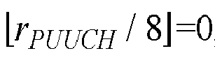


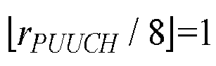


- In some embodiments, the terminal device determines the first PRB index of the target PUCCH resource in the first hop unit and the second PRB index of the target PUCCH resource in the second hop unit according to the number of PRBs in the target PUCCH resource, the PRB offset for the initial uplink BWP, the number of PRBs in the initial uplink BWP, the index of the target PUCCH resource, and the number of initial CS indexes in the set of initial CS indexes.
- In some embodiments, when


- In some embodiments, when





- For example, as illustrated in
FIG. 3 , when NCS is 2, in the first hop unit, two PUCCHs with rPUCCH = 0, 1 occupy NRB PRBs through code-division multiplexing, two PUCCHs with rPUCCH = 2, 3 occupy NRB PRBs through code-division multiplexing, two PUCCHs with rPUCCH = 4, 5 occupy NRB PRBs through code-division multiplexing, two PUCCHs with rPUCCH = 6, 7 occupy NRB PRBs through code-division multiplexing, two PUCCHs with rPUCCH = 14, 15 occupy NRB PRBs through code-division multiplexing, two PUCCHs with rPUCCH = 12, 13 occupy NRB PRBs through code-division multiplexing, two PUCCHs with rPUCCH = 10, 11 occupy NRB PRBs through code-division multiplexing, two PUCCHs with rPUCCH = 8, 9 occupy NRB PRBs through code-division multiplexing. When NCS is 2, in the second hop unit, two PUCCHs with rPUCCH = 0, 1 occupy NRB PRBs through code-division multiplexing, two PUCCHs with rPUCCH = 2, 3 occupy NRB PRBs through code-division multiplexing, two PUCCHs with rPUCCH = 4, 5 occupy NRB PRBs through code-division multiplexing, two PUCCHs with rPUCCH = 6, 7 occupy NRB PRBs through code-division multiplexing, two PUCCHs with rPUCCH = 14, 15 occupy NRB PRBs through code-division multiplexing, two PUCCHs with rPUCCH = 12, 13 occupy NRB PRBs through code-division multiplexing, two PUCCHs with rPUCCH = 10, 11 occupy NRB PRBs through code-division multiplexing, two PUCCHs with rPUCCH = 8, 9 occupy NRB PRBs through code-division multiplexing. - In addition, as illustrated in
FIG. 3 , for PUCCH resources with various indexes rPUCCH, specific PRBs in the target PUCCH resource in different hop units can be determined in different manners. In the first hop unit, the first PRB index is a starting PRB index in all the PRB indexes when rPUCCH ranges from 0 to 7, and the first PRB index is a last PRB index in all the PRB indexes when rPUCCH ranges from 8 to 15. In the second hop unit, the second PRB index is a last PRB index in all the PRB indexes when rPUCCH ranges from 0 to 7, and the second PRB index is a starting PRB index in all the PRB indexes when rPUCCH ranges from 8 to 15. Such a design is conducive to ensuring that an interval between a PRB in the target PUCCH resource in the first hop unit and a PRB in the target PUCCH resource in the second hop unit is relatively large, so that a maximum frequency diversity gain can be obtained through frequency hopping. - In some embodiments, the first PRB index is the starting PRB index in all the PRB indexes of the target PUCCH resource in the first hop unit, and the second PRB index is the starting PRB index in all the PRB indexes of the target PUCCH resource in the second hop unit. Specifically, the first PRB index and the second PRB index can be determined in the following manner. When


- In some embodiments, the first PRB index is the starting PRB index in all the PRB indexes of the target PUCCH resource in the first hop unit, and the second PRB index is the starting PRB index in all the PRB indexes of the target PUCCH resource in the second hop unit. Specifically, the first PRB index and the second PRB index can be determined in the following manner. When


- In some embodiments, the first PRB index is the starting PRB index in all the PRB indexes of the target PUCCH resource in the first hop unit, and the second PRB index is the starting PRB index in all the PRB indexes of the target PUCCH resource in the second hop unit. Specifically, the PRB position of the target PUCCH resource in the initial uplink BWP can be determined in the following manner. When


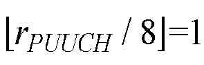


- For example, as illustrated in
FIG. 4 , when NCS is 2, in the first hop unit, two PUCCHs with rPUCCH = 0, 1 occupy NRB PRBs through code-division multiplexing, two PUCCHs with rPUCCH = 2, 3 occupy NRB PRBs through code-division multiplexing, two PUCCHs with rPUCCH = 4, 5 occupy NRB PRBs through code-division multiplexing, two PUCCHs with rPUCCH = 6, 7 occupy NRB PRBs through code-division multiplexing, two PUCCHs with rPUCCH = 14, 15 occupy NRB PRBs through code-division multiplexing, two PUCCHs with rPUCCH = 12, 13 occupy NRB PRBs through code-division multiplexing, two PUCCHs with rPUCCH = 10, 11 occupy NRB PRBs through code-division multiplexing, two PUCCHs with rPUCCH = 8, 9 occupy NRB PRBs through code-division multiplexing. When NCS is 2, in the second hop unit, two PUCCHs with rPUCCH = 0, 1 include NRB PRBs through code-division multiplexing, two PUCCHs with rPUCCH = 2, 3 occupy NRB PRBs through code-division multiplexing, two PUCCHs with rPUCCH = 4, 5 occupy NRB PRBs through code-division multiplexing, two PUCCHs with rPUCCH = 6, 7 occupy NRB PRBs through code-division multiplexing, two PUCCHs with rPUCCH = 14, 15 occupy NRB PRBs through code-division multiplexing, two PUCCHs with rPUCCH = 12, 13 occupy NRB PRBs through code-division multiplexing, two PUCCHs with rPUCCH = 10, 11 occupy NRB PRBs through code-division multiplexing, two PUCCHs with rPUCCH = 8, 9 occupy NRB PRBs through code-division multiplexing. - In addition, as illustrated in
FIG. 4 , for PUCCH resources with various indexes rPUCCH, specific PRBs in the target PUCCH resource in different hop units can be determined in the same manner. In the first hop unit, the first PRB index is a starting PRB index in all the PRB indexes when rPUCCH ranges from 0 to 15. In the second hop unit, the second PRB index is a starting PRB index in all the PRB indexes when rPUCCH ranges from 0 to 15. Such a design is conducive to ensuring that an interval between a PRB of the target PUCCH resource in the first hop unit and a PRB of the target PUCCH resource in the second hop unit is relatively large, so that a maximum frequency diversity gain can be obtained through frequency hopping. Furthermore, it can be ensured that specific PRBs in the target PUCCH resource are determined in a unified manner. - In an initial access phase, it can be defined in a protocol that a PUCCH resource set contains K PUCCH resources, the number of PRBs for each PUCCH transmission is NRB, code-division multiplexing capability provided through initial CS is NCS, and in this case


- For example, when K = 16, NCS = 2, and NRB = 34, 272 ((16/2)*34=272) PRBs are required to support all the PUCCH resources in the PUCCH resource set. For example, in the case where the bandwidth of the initial uplink BWP is 100 MHz, when the SCS is 120 kHz, theoretically, the bandwidth of the initial uplink BWP merely can support 69 (


- In order to ensure coverage, the number of PUCCH resources in the PUCCH resource set needs to be adjusted, so that it can be ensured that the PUCCH resources can be supported by the bandwidth of the initial uplink BWP.
- In some embodiments, the terminal device determines the target PUCCH resource from M PUCCH resources in the target PUCCH resource set, where M is a positive integer and M ≤ K, and K is the number of PUCCH resources in the target PUCCH resource set as defined in the protocol.
- For example, K = 16. That is, it is defined in the protocol that the target PUCCH resource set contains 16 PUCCH resources.
- In some embodiments, the terminal device determines the M PUCCH resources in the target PUCCH resource set according to at least one of: the number of PRBs in the target PUCCH resource, the PRB offset for the initial uplink BWP, the number of PRBs in the initial uplink BWP, or the number of the initial CS indexes in the set of initial CS indexes.
- In a high-frequency scenario, beamforming-based transmission results in a lower probability of user multiplexing in the same beam. Therefore, the number of PUCCH resources in each PUCCH resource set, RPUCCH, can be decreased, i.e., multiplexing capability of the PUCCH resource set can be reduced, which can ensure that the PUCCH resources can be supported by the bandwidth of the initial uplink BWP.
- In some embodiments, the terminal device determines that M is equal to RPUCCH, where


- In some embodiments, the terminal device determines first M PUCCH resources in the K PUCCH resources in the target PUCCH resource set that are defined in the protocol as the M PUCCH resources. For example, K = 16, PUCCH resources with index rPUUCH satisfying 0 ≤ rPUUCH < RPUCCH in the target PUCCH resource set are reserved, and PUCCH resources with index rPUUCH satisfying RPUCCH ≤ rPUUCH ≤ 15 in the target PUCCH resource set are abandoned.
- For example,


FIG. 5 , PUCCH resources with index rPUUCH satisfying 0 ≤ rPUUCH < 8 in the target PUCCH resource set are reserved, and PUCCH resources with index rPUUCH satisfying 8 ≤ rPUUCH ≤ 15 in the target PUCCH resource set are abandoned. Such a design is conducive to ensuring that an interval between a PRB in the target PUCCH resource in the first hop unit and a PRB in the target PUCCH resource in the second hop unit is relatively large, so that a maximum frequency diversity gain can be obtained through frequency hopping. - In some embodiments, the terminal device determines that M is equal to RPUCCH, where


- In some embodiments, the terminal device determines first M PUCCH resources in the K PUCCH resources in the target PUCCH resource set that are defined in the protocol as the M PUCCH resources, i.e., 0 ≤ rPUUCH < M.
- Specifically, for example,


FIG. 6 , the number of PRBs in each of PUCCH resources with index rPUUCH satisfying 0 ≤ rPUUCH < 8 is still NRB which equals 34, and the number of PRBs in each of PUCCH resources with index rPUUCH satisfying rPUUCH = 8, 9 is 24 ((160)mod 34=24). - In some embodiments, when


- In some embodiments, the number of PRBs in each of the M PUCCH resources is NRB when

- In some embodiments, the terminal device determines that M is equal to RPUCCH, where


- In some embodiments, when the terminal device determines that M is equal to RPUCCH, and RPUCCH is further adjusted to be the multiple of 2 * NCS by rounding down the calculation result, the terminal device determines first M PUCCH resources in the K PUCCH resources in the target PUCCH resource set that are defined in the protocol as the M PUCCH resources, i.e., 0 ≤ rPUUCH < M.
- In some embodiments, when the terminal device determines that M is equal to RPUCCH, and RPUCCH is further adjusted to be the multiple of 2 * NCS by rounding down the calculation result, the number of PRBs in each of the M PUCCH resources is NRB.
- In some embodiments, when the terminal device determines that M is equal to RPUCCH and RPUCCH is further adjusted to be the multiple of 2 * NCS by rounding down the calculation result, it can be defined that R= RPUCCH /2.
- Specifically, for example, when




- Specifically, for example,


FIG. 7 , K = 16, PUCCH resources with index rPUUCH satisfying 0 ≤ rPUUCH < 8 in the target PUCCH resource set are reserved, and PUCCH resources with index rPUUCH satisfying 8 ≤ rPUUCH ≤ 15 in the target PUCCH resource set are abandoned. In this case, R= RPIUCCH /2 = 4, and specifically, for example, mapping of rPUUCH to a PRB index is as follows. When



- In some embodiments, when the terminal device determines that M is equal to RPUCCH, and RPUCCH is further adjusted to be the multiple of 2 * NCS by rounding down the calculation result, the terminal device determines that the M PUCCH resources include: first M/2 PUCCH resources in first K/2 PUCCH resources in the K PUCCH resources in the target PUCCH resource set that are defined in the protocol, and first M/2 PUCCH resources in last K/2 PUCCH resources in the K PUCCH resources in the target PUCCH resource set that are defined in the protocol, i.e, 0 ≤ rPUUCH < M/2 and K/2 ≤ rPUUCH < K/2 + M/2.
- Specifically, for example,


FIG. 8 , K = 16, PUCCH resources with index rPUUCH satisfying 0 ≤ rPUUCH < 4 and 8 ≤ rPUUCH < 12 in the target PUCCH resource set are reserved, PUCCH resources with index rPUUCH satisfying 4 ≤ rPUUCH < 8 and 12 ≤ rPUUCH < 16 in the target PUCCH resource set are abandoned, and the number of PRBs in each of the M PUCCH resources is NRB, i.e., 34. - In some embodiments, the terminal device determines that M is RPUCCH +2 * NCS, where



- In some embodiments, when the terminal device determines that M is RPUCCH +2 * NCS, and RPUCCH is further adjusted to be the multiple of 2 * NCS by rounding down the calculation result, the terminal device determines first M PUCCH resources in the K PUCCH resources in the target PUCCH resource set that are defined in the protocol as the M PUCCH resources, i.e., 0 ≤ rPUUCH < M.
- In some embodiments, when the terminal device determines that M is RPUCCH +2 * NCS, and RPUCCH is further adjusted to be the multiple of 2 * NCS by rounding down the calculation result, the number of PRBs in each of PUCCH resources with resource indexes from 0 to R - NCS - 1 in the M PUCCH resources is NRB, the number of PRBs in each of PUCCH resources with resource indexes from R to RPUCCH + NCS - 1 in the M PUCCH resources is NRB, the number of PRBs in each of PUCCH resources with resource indexes from R - NCS to R - 1 in the M PUCCH resources is


- Specifically, for example,


FIG. 9 , the number of PRBs in each of PUCCH resources with index rPUUCH satisfying 0 ≤ rPUUCH < 4 and 6 ≤ rPUUCH < 10 is still NRB which equals 34, and the number of PRBs in each of PUCCH resources with index rPUUCH satisfying 4 ≤ rPUUCH < 6 and 10 ≤ rPUUCH < 12 is 12 (
- In some embodiments, when the terminal device determines that M is RPUCCH +2 * NCS, and RPUCCH is further adjusted to be the multiple of 2 * NCS by rounding down the calculation result, the terminal device determines that the M PUCCH resources include: first M/2 PUCCH resources in first K/2 PUCCH resources in the K PUCCH resources in the target PUCCH resource set that are defined in the protocol, and first M/2 PUCCH resources in last K/2 PUCCH resources in the K PUCCH resources in the target PUCCH resource set that are defined in the protocol, i.e., 0 ≤ rPUUCH < M/2 and K/2 ≤ rPUUCH < K/2 + M/2.
- In some embodiments, when the terminal device determines that M is RPUCCH +2 * NCS, and RPUCCH is further adjusted to be the multiple of 2 * NCS by rounding down the calculation result, the number of PRBs in each of PUCCH resources with resource indexes from 0 to RPUCCH / 2 - 1 in the M PUCCH resources is NRB, the number of PRBs in each of PUCCH resources with resource indexes from K / 2 to K / 2 + RPUCCH / 2 - 1 in the M PUCCH resources is NRB, the number of PRBs in each of PUCCH resources with resource indexes from RPUCCH / 2 to RPUCCH / 2 + NCS - 1 in the M PUCCH resources is


- Specifically, for example,



FIG. 10 , the number of PRBs in each of PUCCH resources with indexes rPUUCH satisfying 0 ≤ rPUUCH < 4 and 8 ≤ rPUUCH < 12 is still NRB which equals 34, and the number of PRBs in each of PUCCH resources with indexes rPUUCH satisfying 4 ≤ rPUUCH < 6 and 12 ≤ rPUUCH < 14 is
- In some embodiments, a value of M is pre-configured or specified in the protocol. Specifically, for example, different initial uplink BWPs correspond to different values of M, respectively. That is, the value of M is set to ensure that the PUCCH resources in the target PUCCH resource set can be supported by a bandwidth of the initial uplink BWP. For example, as illustrated in Table 3, when the bandwidth of the initial uplink BWP is 100 MHz,


Table 3 Bandwidth of initial uplink BWP (MHz) 
100 2 200 4 400 8 - It is to be noted that, in Table 3 above, the SCS of 120 kHz is merely taken as an example for illustration, and other SCSs are also applicable.
- In some embodiments, the value of M is configured by the network device via system information (e.g., SIB1). Specifically, for example, different PUCCH-resource-number indexes correspond to different values of M, respectively, where the PUCCH-resource-number index indicates the number of PUCCH resources in the target PUCCH resource set. For example, as illustrated in Table 4, PUCCH-resource-
number index 0 corresponds to
number index 1 corresponds to


number index 0 may indicate that the target PUCCH resource set contains two PUCCH resources as an example, PUCCH-resource-number index 1 may indicate that the target PUCCH resource set contains four PUCCH resources as an example, PUCCH-resource-number index 2 may indicate that the target PUCCH resource set contains eight PUCCH resources as an example, and PUCCH-resource-number index 3 may indicate that the target PUCCH resource set contains 16 PUCCH resources as an example.Table 4 PUCCH-resource-number index 
0 1 1 2 2 4 3 8 - In some embodiments, the value of M is indicated by the network device via at least one bit in the PUCCH resource indicator field in downlink scheduling signaling. For example, the network device indicates that M = 4 via one bit in the PUCCH resource indicator field in the downlink scheduling signaling. The network device indicates that M = 8 via 2 bits in the PUCCH resource indicator field in the downlink scheduling signaling. The network device indicates that M = 16 via 3 bits in the PUCCH resource indicator field in the downlink scheduling signaling. For specific indication manners, reference can be made to the indication manner in the formula 2 above, which will not be repeated herein for the sake of simplicity.
- In some embodiments, the target PUCCH resource set contains multiple first symbols, and/or, the target PUCCH resource set contains multiple orthogonal cover codes (OCCs). Therefore, it can be ensured that all the K PUCCH resources in the target PUCCH resource set can be supported, and K is the number of PUCCH resources in the PUCCH resource set as defined in a protocol. In addition, an interval between a frequency-domain location of each PUCCH resource in the first hop unit and a frequency-domain location of each PUCCH resource in the second hop unit can be set to be relatively large, so that a maximum gain can be obtained through frequency hopping.
- It is to be noted that, the OCC may also be referred to as a time-domain spreading code.
- In some embodiments, the target PUCCH resource set contains the multiple first symbols, the number of the multiple first symbols is L, and in each of the multiple first symbols transmission of

- For example, taking
index 0 in Table 2 above as an example, K = 16, and as illustrated in Table 5, the first symbols {6, 8, 10, 12} are added, and in each of the first symbols transmission of four PUCCHs is supported through frequency-division multiplexing and code-division multiplexing, thereby ensuring that all 16 PUCCH resources in the target PUCCH resource set can be supported. In addition, as illustrated inFIG. 11 , an interval between a frequency-domain location of each PUCCH resource in the first hop unit and a frequency-domain location of each PUCCH resource in the second hop unit are relatively large. Therefore, a maximum gain can be obtained through frequency hopping.Table 5 Index PUCCH format First symbol Number of symbols PRB offset 
Set of initial CS indexes 0 0 6, 8, 10, 12 2 0 {0, 3} - In some embodiments, prior to introduction of time-domain multiplexing, frequency-domain space in the initial uplink BWP can be fully utilized, which can minimize the number of symbols additionally introduced.
- For example, taking
index 0 in Table 2 above as an example, K = 16, and as illustrated in Table 6, the first symbols {10, 12} are added, and in each of the first symbols, transmission of eight PUCCHs is supported through frequency-division multiplexing and code-division multiplexing, thereby ensuring that all 16 PUCCH resources in the target PUCCH resource set can be supported. In addition, as illustrated inFIG. 12 , an interval between a frequency-domain location of each PUCCH resource in the first hop unit and a frequency-domain location of each PUCCH resource in the second hop unit is the largest. Therefore, a maximum gain can be obtained through frequency hopping.Table 6 Index PUCCH format First symbol Number of symbols PRB offset 
Set of initial CS indexes 0 0 10, 12 2 0 {0, 3} - In some embodiments, the target PUCCH resource set contains the multiple OOCs. The number of the multiple OOCs is S, and in each of the first symbols transmission of

PUCCH format 1. Therefore, based onOOC 0, an additional OCC(s) can be introduced to support 16 PUCCH resources. - For example, taking
index 7 in Table 2 above as an example, K = 16, and as illustrated in Table 7, indexes of the OCC {0, 1} are added, and in each of the first symbols transmission of eight PUCCHs is supported through frequency-division multiplexing and code-division multiplexing, thereby ensuring that all 16 PUCCH resources in the target PUCCH resource set can be supported. In this case, as illustrated inFIG. 13 , although an interval between a frequency-domain location of each PUCCH resource in the first hop unit and a frequency-domain location of each PUCCH resource in the second hop unit may not be the largest, only one additional OCC index is required.Table 7 Index PUCCH format First symbol Number of symbols PRB offset 
Set of initial CS indexes OCC 7 1 4 10 0 {0, 6} 0, 1 - In some embodiments, considering that the number of time-domain symbols when frequency hopping is used is twice the number of time-domain symbols when frequency hopping is not used, in a case where frequency hopping is not used, respective PUCCH transmissions can be performed through remaining time-domain resources, so that transmission of 16 PUCCHs can be supported.
- For example, taking
index 0 in Table 2 above as an example, K = 16. When frequency hopping is used,symbol 12 corresponds to the first hop unit, andsymbol 13 corresponds to the second hop unit, and only 8 PUCCH resources can be supported. However, as illustrated inFIG. 14 , when frequency hopping is not used,symbol 13 can be used for transmission of other eight PUCCH resources, and thus it can be realized that two symbols can support 16 PUCCH resources. - Embodiments of the disclosure are designed based on the unlicensed band of 60 GHz. However, a scheme for PRB position determination and a scheme for adjusting the number of PUCCH resources in a PUCCH resource set are applicable to a PUCCH transmission on multiple PRBs in any band.
- Therefore, in embodiments of the disclosure, the terminal device determines the PRB position of the target PUCCH resource for the PUCCH in the initial uplink BWP, where the target PUCCH resource includes at least one PRB per hop unit, i.e., the target PUCCH resource includes multiple PRBs in multiple hop units. Therefore, transmission of the PUCCH on multiple PRBs can be supported, which can enhance coverage of the transmission of the PUCCH.
- The embodiments of the disclosure at the terminal side are described in detail above with reference to
FIG. 2 to FIG. 14 , and embodiments of the disclosure at the network side will be described in detail below with reference toFIG. 15 . It is to be understood that the embodiments at the network side correspond to the embodiments at the terminal side, and for similar illustrations, reference can be made to the embodiments at the terminal side. -
FIG. 15 is a schematic flow chart of amethod 300 for wireless communication according to embodiments of the disclosure. As illustrated inFIG. 15 , themethod 300 for wireless communication may include at least some of the following. - S310, a network device transmits indication information to a terminal device, where the indication information indicates M PUCCH resources in a target PUCCH resource set, the M PUCCH resources include a target PUCCH resource, the target PUCCH resource includes at least one PRB per hop unit, M is a positive integer and M ≤ K, and K is the number of PUCCH resources in a PUCCH resource set as defined in a protocol.
- S320, the network device receives a PUCCH transmitted on the target PUCCH resource by the terminal device.
- In some embodiments, different initial uplink BWPs correspond to different values of M, respectively.
- In some embodiments, the indication information is transmitted via system information.
- In some embodiments, different PUCCH-resource-number indexes correspond to different values of M, respectively, where the PUCCH-resource-number index indicates the number of PUCCH resources in the target PUCCH resource set.
- In some embodiments, the indication information is at least one bit in a PUCCH resource indicator field in downlink scheduling signaling.
- In some embodiments, the target PUCCH resource set contains multiple first symbols, and/or, the target PUCCH resource set contains multiple OCCs.
- In some embodiments, the target PUCCH resource set contains the multiple first symbols, the number of the multiple first symbols is L, and in each of the multiple first symbols transmission of

- In some embodiments, the target PUCCH resource set contains the multiple OCCs, the number of the multiple OCCs is S, and in each of the first symbols transmission of

- In some embodiments, considering that the number of time-domain symbols when frequency hopping is used is twice the number of time-domain symbols when frequency hopping is not used, in a case where frequency hopping is not used, respective PUCCH transmissions can be performed through remaining time-domain resources, so that transmission of 16 PUCCHs can be supported.
- In some embodiments, the target PUCCH resource is a common PUCCH resource configured for a terminal device in an unconnected state.
- In some embodiments, a format of the PUCCH includes one of:
PUCCH format 0,PUCCH format 1, and PUCCH format 4. - Therefore, in embodiments of the disclosure, the terminal device determines the PRB position of the target PUCCH resource for the PUCCH in the initial uplink BWP, where the target PUCCH resource includes at least one PRB per hop unit, i.e., the target PUCCH resource includes multiple PRBs in multiple hop units. Therefore, transmission of the PUCCH on multiple PRBs can be supported, which can enhance coverage of the transmission of the PUCCH.
- The method embodiments of the disclosure are described in detail above with reference to
FIG. 2 to FIG. 15 , and apparatus embodiments of the disclosure will be described in detail below with reference toFIG. 16 to FIG. 17 . It is to be understood that the apparatus embodiments and the method embodiments correspond to each other, and for similar illustrations, reference can be made to the method embodiments. -
FIG. 16 illustrates a schematic block diagram of aterminal device 400 according to embodiments of the disclosure. As illustrated inFIG. 16 , theterminal device 400 includes aprocessing unit 410 and acommunication unit 420. Theprocessing unit 410 is configured to determine a PRB position of a target PUCCH resource for a PUCCH in an initial uplink BWP, where the target PUCCH resource includes at least one PRB per hop unit. Thecommunication unit 420 is configured to transmit the PUCCH on the target PUCCH resource. - In some embodiments, the number of PRBs in the target PUCCH resource is determined according to a preset rule.
- In some embodiments, the
processing unit 410 is specifically configured to determine a first PRB index of the target PUCCH resource in a first hop unit and a second PRB index of the target PUCCH resource in a second hop unit according to at least one of: the number of PRBs in the target PUCCH resource, a PRB offset for the initial uplink BWP, the number of PRBs in the initial uplink BWP, an index of the target PUCCH resource, or the number of initial cyclic shift (CS) indexes in a set of initial CS indexes. Theprocessing unit 410 is further configured to determine the PRB position of the target PUCCH resource in the initial uplink BWP according to the first PRB index, the second PRB index, and the number of PRBs in the target PUCCH resource. - In some embodiments, the first PRB index is a starting PRB index in all PRB indexes of the target PUCCH resource in the first hop unit, or, the first PRB index is a last PRB index in all the PRB indexes of the target PUCCH resource in the first hop unit, or, the first PRB index is an intermediate PRB index in all the PRB indexes of the target PUCCH resource in the first hop unit. And/or, the second PRB index is a starting PRB index in all PRB indexes of the target PUCCH resource in the second hop unit, or, the second PRB index is a last PRB index in all the PRB indexes of the target PUCCH resource in the second hop unit, or, the second PRB index is an intermediate PRB index in all the PRB indexes of the target PUCCH resource in the second hop unit.
- In some embodiments, the
processing unit 410 is specifically configured to determine the first PRB index as





- In some embodiments, the
processing unit 410 is specifically configured to determine that PRB indexes of the target PUCCH resource in the first hop unit in the initial uplink BWP is from


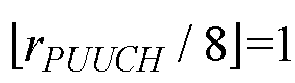


- In some embodiments, the
processing unit 410 is specifically configured to determine the first PRB index as


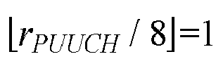


- In some embodiments, the
processing unit 410 is specifically configured to determine that PRB indexes of the target PUCCH resource in the first hop unit in the initial uplink BWP are from


- In some embodiments, the
processing unit 410 is further configured to determine the target PUCCH resource from M PUCCH resources in a target PUCCH resource set, where M is a positive integer and M ≤ K, and K is the number of PUCCH resources in the target PUCCH resource set as defined in a protocol. - In some embodiments, the
processing unit 410 is further configured to determine the MPUCCH resources in the target PUCCH resource set according to at least one of: the number of PRBs in the target PUCCH resource, the PRB offset for the initial uplink BWP, the number of PRBs in the initial uplink BWP, or the number of initial CS indexes in the set of initial CS indexes. - In some embodiments, the
processing unit 410 is specifically configured to determine that M is equal to RPUCCH, where


- In some embodiments, the
processing unit 410 is specifically configured to determine first M PUCCH resources in the K PUCCH resources in the target PUCCH resource set that are defined in the protocol as the M PUCCH resources. - In some embodiments, when


- In some embodiments, the number of PRBs in each of the M PUCCH resources is NRB when

- In some embodiments, the
processing unit 410 is specifically configured to: determine that M is equal to RPUCCH, or, determine that M is RPUCCH +2 * NCS, where RPUCCH =


- In some embodiments, the
processing unit 410 is specifically configured to determine first M PUCCH resources in the K PUCCH resources in the target PUCCH resource set that are defined in the protocol as the M PUCCH resources. - In some embodiments, in the case where the terminal device determines that M is equal to RPUCCH, and RPUCCH is further adjusted to be the multiple of 2 * NCS by rounding down the calculation result, when



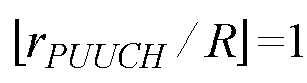


R PIUCCH12. - In some embodiments, when the terminal device determines that M is RPUCCH +2 * NCS, and RPUCCH is further adjusted to be the multiple of 2 * NCS by rounding down the calculation result, the number of PRBs in each of PUCCH resources with resource indexes from 0 to R - NCS - 1 in the M PUCCH resources is NRB, the number of PRBs in each of PUCCH resources with resource indexes from R to RPUCCH + NCS - 1 in the M PUCCH resources is NRB, the number of PRBs in each of PUCCH resources with resource indexes from R - NCS to R - 1 in the M PUCCH resources is


- In some embodiments, the
processing unit 410 is specifically configured to determine that the M PUCCH resources include: first M/2 PUCCH resources in first K/2 PUCCH resources in the K PUCCH resources in the target PUCCH resource set that are defined in the protocol, and first M/2 PUCCH resources in last K/2 PUCCH resources in the K PUCCH resources in the target PUCCH resource set that are defined in the protocol. - In some embodiments, when the terminal device determines that M is RPUCCH +2 * NCS, and RPUCCH is further adjusted to be the multiple of 2 * NCS by rounding down the calculation result, the number of PRBs in each of PUCCH resources with resource indexes from 0 to RPUCCH / 2 - 1 in the M PUCCH resources is NRB, the number of PRBs in each of PUCCH resources with resource indexes from K / 2 to K / 2 +RPUCCH / 2 - 1 in the M PUCCH resources is NRB, the number of PRBs in each of PUCCH resources with resource indexes from RPUCCH /2 to RPUCCH /2 + NCS - 1 in the M PUCCH resources is


- In some embodiments, the number of PRBs in each of the M PUCCH resources is NRB when the terminal device determines that M is equal to RPUCCH and RPUCCH is further adjusted to be the multiple of 2 * NCS by rounding down the calculation result.
- In some embodiments, a value of M is pre-configured or specified in the protocol.
- In some embodiments, different initial uplink BWPs correspond to different values of M, respectively.
- In some embodiments, a value of M is configured by a network device via system information.
- In some embodiments, different PUCCH-resource-number indexes correspond to different values of M, respectively, where the PUCCH-resource-number index indicates the number of PUCCH resources in the target PUCCH resource set.
- In some embodiments, the value of M is indicated by the network device via at least one bit in a PUCCH resource indicator field in downlink scheduling signaling.
- In some embodiments, the target PUCCH resource set contains multiple first symbols, and/or, the target PUCCH resource set contains multiple OCCs.
- In some embodiments, the target PUCCH resource set contains the multiple first symbols, the number of the multiple first symbols is L, and in each of the multiple first symbols transmission of

- In some embodiments, the target PUCCH resource set contains the multiple OCCs, the number of the multiple OCCs is S, and in each of the first symbols transmission of

- In some embodiments, the target PUCCH resource is a common PUCCH resource configured for a terminal device in an unconnected state.
- In some embodiments, the
processing unit 410 is further configured to determine an index of the target PUCCH resource from a target PUCCH resource set according to the following formula:
- In some embodiments, a format of the PUCCH includes one of:
PUCCH format 0,PUCCH format 1, and PUCCH format 4. - In some embodiments, the communication unit above may be a communication interface or a transceiver, or may be an input/output interface of a communication chip or a system-on-chip (SOC). The processing unit above may be one or more processors.
- It is to be understood that, the
terminal device 400 according to embodiments of the disclosure may correspond to the terminal device in the method embodiments of the disclosure, and the foregoing and other operations and/or functions of various units in theterminal device 400 are respectively intended for implementing corresponding procedures of the terminal device in themethod 200 for wireless communication illustrated inFIG. 2 to FIG. 14 , which will not be repeated herein for the sake of simplicity. -
FIG. 17 illustrates a schematic block diagram of anetwork device 500 according to embodiments of the disclosure. As illustrated inFIG. 17 , thenetwork device 500 includes acommunication unit 510. Thecommunication unit 510 is configured to transmit indication information to a terminal device, where the indication information indicates M PUCCH resources in a target PUCCH resource set, the M PUCCH resources include a target PUCCH resource, the target PUCCH resource includes at least one PRB per hop unit, M is a positive integer and M ≤ K, and K is the number of PUCCH resources in a PUCCH resource set as defined in a protocol. Thecommunication unit 510 is further configured to receive a PUCCH transmitted on the target PUCCH resource by the terminal device. - In some embodiments, different initial uplink BWPs correspond to different values of M.
- In some embodiments, the indication information is transmitted via system information.
- In some embodiments, different PUCCH-resource-number indexes correspond to different values of M, respectively, where the PUCCH-resource-number index indicates the number of PUCCH resources in the target PUCCH resource set.
- In some embodiments, the indication information is at least one bit in a PUCCH resource indicator field in downlink scheduling signaling.
- In some embodiments, the target PUCCH resource set contains multiple first symbols, and/or, the target PUCCH resource set contains multiple OCCs.
- In some embodiments, the target PUCCH resource set contains the multiple first symbols, the number of the multiple first symbols is L, and in each of the multiple first symbols transmission of

- In some embodiments, the target PUCCH resource set contains the multiple OCCs, the number of the multiple OCCs is S, and in each of the first symbols transmission of

- In some embodiments, the target PUCCH resource is a common PUCCH resource configured for a terminal device in an unconnected state.
- In some embodiments, a format of the PUCCH includes one of:
PUCCH format 0,PUCCH format 1, and PUCCH format 4. - In some embodiments, the communication unit above may be a communication interface or a transceiver, or may be an input/output interface of a communication chip or an SOC.
- It is to be understood that, the
network device 500 according to embodiments of the disclosure may correspond to the network device in the method embodiments of the disclosure, and the foregoing and other operations and/or functions of various units in thenetwork device 500 are respectively intended for implementing corresponding procedures of the network device in themethod 300 for wireless communication illustrated inFIG. 15 , which will not be repeated herein for the sake of simplicity. -
FIG. 18 is a schematic structural diagram of acommunication device 600 provided in embodiments of the disclosure. Thecommunication device 600 illustrated inFIG. 18 includes aprocessor 610. Theprocessor 610 can invoke and execute a computer program stored in a memory, so as to implement the method in embodiments of the disclosure. - In some embodiments, as illustrated in
FIG. 18 , thecommunication device 600 may further include amemory 620. Theprocessor 610 can invoke and execute a computer program stored in thememory 620, so as to implement the method in embodiments of the disclosure. - The
memory 620 may be a separate device independent of theprocessor 610, or may be integrated into theprocessor 610. - In some embodiments, as illustrated in
FIG. 18 , thecommunication device 600 may further include atransceiver 630. Theprocessor 610 can control thetransceiver 630 to communicate with other devices, specifically, to transmit information or data to other devices or to receive information or data from other devices. - The
transceiver 630 may include a transmitter and a receiver. Thetransceiver 630 may further include an antenna, where one or more antennas may be provided. - In some embodiments, the
communication device 600 may specifically be the network device in embodiments of the disclosure, and thecommunication device 600 may implement corresponding operations implemented by the network device in various methods in embodiments of the disclosure, which will not be repeated herein for the sake of simplicity. - In some embodiments, the
communication device 600 may specifically be the terminal device in embodiments of the disclosure, and thecommunication device 600 may implement corresponding operations implemented by the terminal device in various methods in embodiments of the disclosure, which will not be repeated herein for the sake of simplicity. -
FIG. 19 is a schematic structural diagram of an apparatus according to embodiments of the disclosure. The apparatus 700 illustrated inFIG. 19 includes aprocessor 710. Theprocessor 710 can invoke and execute a computer program stored in a memory, so as to implement the method in embodiments of the disclosure. - In some embodiments, as illustrated in
FIG. 19 , the apparatus 700 may further include amemory 720. Theprocessor 710 can invoke and execute a computer program stored in thememory 720, so as to implement the method in embodiments of the disclosure. - The
memory 720 may be a separate device independent of theprocessor 710, or may be integrated into theprocessor 710. - In some embodiments, the apparatus 700 may further include an
input interface 730. Theprocessor 710 can control theinput interface 730 to communicate with other devices or chips, and specifically, to obtain information or data transmitted by other devices or chips. - In some embodiments, the apparatus 700 may further include an
output interface 740. Theprocessor 710 can control theoutput interface 740 to communicate with other devices or chips, and specifically, to output information or data to other devices or chips. - In some embodiments, the apparatus may be applied to the network device in embodiments of the disclosure, and the apparatus may implement corresponding operations implemented by the network device in various methods in embodiments of the disclosure, which will not be repeated herein for the sake of simplicity.
- In some embodiments, the apparatus may be applied to the terminal device in embodiments of the disclosure, and the apparatus may implement corresponding operations implemented by the terminal device in various methods in embodiments of the disclosure, which will not be repeated herein for the sake of simplicity.
- In some embodiments, the apparatus in embodiments of the disclosure may also be a chip, for example, a system-on-a-chip (SoC).
-
FIG. 20 is a schematic block diagram of a communication system 800 provided in embodiments of the disclosure. As illustrated inFIG. 20 , the communication system 800 includes aterminal device 810 and anetwork device 820. - The
terminal device 810 may be configured to implement corresponding functions implemented by the terminal device in the foregoing methods, and thenetwork device 820 may be configured to implement corresponding functions implemented by the network device in the foregoing methods, which will not be repeated herein for the sake of simplicity. - It is to be understood that, the processor in embodiments of the disclosure may be an integrated circuit chip with signal processing capabilities. During implementation, each step of the foregoing method embodiments may be completed by an integrated logic circuit of hardware in the processor or an instruction in the form of software. The processor may be a general-purpose processor, a digital signal processor (DSP), an application specific integrated circuit (ASIC), a field programmable gate array (FPGA), or other programmable logic devices, discrete gates or transistor logic devices, discrete hardware components. The methods, steps, and logic blocks disclosed in embodiments of the disclosure can be implemented or executed. The general-purpose processor may be a microprocessor, or the processor may be any conventional processor or the like. The steps of the method disclosed in embodiments of the disclosure may be directly implemented by a hardware decoding processor, or may be performed by hardware and software modules in the decoding processor. The software module can be located in a storage medium mature in the skill such as a random access memory (RAM), a flash memory, a read-only memory (ROM), a programmable ROM (PROM), or an electrically erasable programmable memory, registers, and the like. The storage medium is located in the memory. The processor reads the information in the memory, and completes the steps of the method described above with the hardware of the processor.
- It is to be understood that, the memory in embodiments of the disclosure may be a volatile memory or a non-volatile memory, or may include both the volatile memory and the non-volatile memory. The non-volatile memory may be a ROM, a PROM, an erasable PROM (EPROM), an electrically EPROM (EEPROM), or flash memory. The volatile memory may be a RAM that acts as an external cache. By way of example but not limitation, many forms of RAM are available, such as a static RAM (SRAM), a dynamic RAM (DRAM), a synchronous DRAM (SDRAM), a double data rate SDRAM (DDR SDRAM), an enhanced SDRAM (ESDRAM), a synchlink DRAM (SLDRAM), and a direct rambus RAM (DR RAM). It is to be noted that, the memory of the systems and methods described in the disclosure is intended to include, but is not limited to, these and any other suitable types of memory.
- It is to be understood that, the memory above is intended for illustration rather than limitation. For example, the memory in embodiments of the disclosure may also be an SRAM, a DRAM, an SDRAM, a DDR SDRAM, an ESDRAM, an SLDRAM, a DR RAM, etc. In other words, the memory in embodiments of the disclosure is intended to include, but is not limited to, these and any other suitable types of memory.
- Embodiments of the disclosure further provide a computer-readable storage medium. The computer-readable storage medium is configured to store a computer program.
- In some embodiments, the computer-readable storage medium may be applied to the network device in embodiments of the disclosure, and the computer program is operable with a computer to execute corresponding operations implemented by the network device in various methods in embodiments of the disclosure, which will not be repeated herein for the sake of brevity.
- In some embodiments, the computer-readable storage medium may be applied to the terminal device in embodiments of the disclosure, and the computer program is operable with a computer to execute corresponding operations implemented by the terminal device in various methods in embodiments of the disclosure, which will not be repeated herein for the sake of brevity.
- Embodiments of the disclosure further provide a computer program product. The computer program product includes computer program instructions.
- In some embodiments, the computer program product may be applied to the network device in embodiments of the disclosure, and the computer program instructions are operable with a computer to execute corresponding operations implemented by the network device in various methods in embodiments of the disclosure, which will not be repeated herein for the sake of brevity.
- In some embodiments, the computer program product may be applied to the terminal device in embodiments of the disclosure, and the computer program instructions are operable with a computer to execute corresponding operations implemented by the terminal device in various methods in embodiments of the disclosure, which will not be repeated herein for the sake of brevity.
- Embodiments of the disclosure further provide a computer program.
- In some embodiments, the computer program may be applied to the network device in embodiments of the disclosure. The computer program, when executed by a computer, is operable with the computer to implement corresponding operations implemented by the network device in various methods in embodiments of the disclosure, which will not be repeated herein for the sake of brevity.
- In some embodiments, the computer program may be applied to the terminal device in embodiments of the disclosure. The computer program, when executed by a computer, is operable with the computer to implement corresponding operations implemented by the terminal device in various methods in embodiments of the disclosure, which will not be repeated herein for the sake of brevity.
- It will be appreciated by those of ordinary skill in the art that units and algorithmic operations of various examples described in connection with embodiments of the disclosure can be implemented by electronic hardware or by a combination of computer software and electronic hardware. Whether these functions are performed by means of hardware or software depends on the application and the design constraints of the associated technical solution. Those skilled in the art may use different methods with regard to each particular application to implement the described functionality, but such methods should not be regarded as lying beyond the scope of the disclosure.
- It will be evident to those skilled in the art that, for the sake of convenience and brevity, in terms of the specific working processes of the foregoing systems, apparatuses, and units, reference can be made to the corresponding processes in the foregoing method embodiments, which will not be repeated herein.
- It will be appreciated that the systems, apparatuses, and methods disclosed in embodiments of the disclosure may also be implemented in various other manners. For example, the above apparatus embodiments are merely illustrative, e.g., the division of units is only a division of logical functions, and other manners of division may be available in practice, e.g., multiple units or assemblies may be combined or may be integrated into another system, or some features may be ignored or skipped. In other respects, the coupling or direct coupling or communication connection as illustrated or discussed may be an indirect coupling or communication connection through some interface, device, or unit, and may be electrical, mechanical, or otherwise.
- Separated units as illustrated may or may not be physically separated. Components displayed as units may or may not be physical units, and may reside at one location or may be distributed to multiple networked units. Some or all of the units may be selectively adopted according to practical needs to achieve desired objectives of the disclosure.
- In addition, various functional units described in various embodiments of the disclosure may be integrated into one processing unit or may be present as a number of physically separated units, and two or more units may be integrated into one.
- If the functions are implemented as software functional units and sold or used as standalone products, they may be stored in a computer-readable storage medium. Based on such an understanding, the essential technical solution, or the portion that contributes to the prior art, or part of the technical solution of the disclosure may be embodied as software products. The computer software products can be stored in a storage medium and may include multiple instructions that, when executed, can cause a computer device, e.g., a personal computer, a server, a network device, etc., to execute some or all operations of the methods described in various embodiments of the disclosure. The above storage medium may include various kinds of media that can store program codes, such as a universal serial bus (USB) flash disk, a mobile hard drive, an ROM, an RAM, a magnetic disk, or an optical disk.
- The foregoing elaborations are merely embodiments of the disclosure, but are not intended to limit the protection scope of the disclosure. Any variation or replacement easily thought of by those skilled in the art within the technical scope disclosed in the disclosure shall belong to the protection scope of the disclosure. Therefore, the protection scope of the disclosure shall be subject to the protection scope of the claims.
Claims (94)
- A method for wireless communication, comprising:determining, by a terminal device, a physical resource block (PRB) position of a target physical uplink control channel (PUCCH) resource for a PUCCH in an initial uplink bandwidth part (BWP), the target PUCCH resource comprising at least one PRB per hop unit; andtransmitting, by the terminal device, the PUCCH on the target PUCCH resource.
- The method of claim 1, wherein the number of PRBs in the target PUCCH resource is determined according to a preset rule.
- The method of claim 2, wherein determining, by the terminal device, the PRB position of the target PUCCH resource for the PUCCH in the initial uplink BWP comprises:determining, by the terminal device, a first PRB index of the target PUCCH resource in a first hop unit and a second PRB index of the target PUCCH resource in a second hop unit according to at least one of: the number of PRBs in the target PUCCH resource, a PRB offset for the initial uplink BWP, the number of PRBs in the initial uplink BWP, an index of the target PUCCH resource, or the number of initial cyclic shift (CS) indexes in a set of initial CS indexes; anddetermining, by the terminal device, the PRB position of the target PUCCH resource in the initial uplink BWP according to the first PRB index, the second PRB index, and the number of PRBs in the target PUCCH resource.
- The method of claim 3, whereinthe first PRB index is a starting PRB index in all PRB indexes of the target PUCCH resource in the first hop unit, or, the first PRB index is a last PRB index in all the PRB indexes of the target PUCCH resource in the first hop unit, or, the first PRB index is an intermediate PRB index in all the PRB indexes of the target PUCCH resource in the first hop unit; and/orthe second PRB index is a first PRB index in all PRB indexes of the target PUCCH resource in the second hop unit, or, the second PRB index is a last PRB index in all the PRB indexes of the target PUCCH resource in the second hop unit, or, the second PRB index is an intermediate PRB index in all the PRB indexes of the target PUCCH resource in the second hop unit.
- The method of claim 3 or 4, wherein determining, by the terminal device, the first PRB index of the target PUCCH resource in the first hop unit and the second PRB index of the target PUCCH resource in the second hop unit according to at least one of: the number of PRBs in the target PUCCH resource, the PRB offset for the initial uplink BWP, the number of PRBs in the initial uplink BWP, the index of the target PUCCH resource, or the number of initial CS indexes in the set of initial CS indexes comprises:when


 when
when


 NRB is the number of PRBs in the target PUCCH resource, rPUUCH is the index of the target PUCCH resource,

- The method of any one of claims 3 to 5, wherein determining, by the terminal device, the PRB position of the target PUCCH resource in the initial uplink BWP according to the first PRB index, the second PRB index, and the number of PRBs in the target PUCCH resource comprises:when


 when
when


 NRB is the number of PRBs in the target PUCCH resource, rPUUCH is the index of the target PUCCH resource,



- The method of claim 3 or 4, wherein determining, by the terminal device, the first PRB index of the target PUCCH resource in the first hop unit and the second PRB index of the target PUCCH resource in the second hop unit according to at least one of: the number of PRBs in the target PUCCH resource, the PRB offset for the initial uplink BWP, the number of PRBs in the initial uplink BWP, the index of the target PUCCH resource, or the number of initial CS indexes in the set of initial CS indexes comprises:when


 when
when

 NRB is the number of PRBs in the target PUCCH resource, rPUUCH is the index of the target PUCCH resource,

- The method of claim 3, 4, or 7, wherein determining, by the terminal device, the PRB position of the target PUCCH resource in the initial uplink BWP according to the first PRB index, the second PRB index, and the number of PRBs in the target PUCCH resource comprises:when


 when
when


 NRB is the number of PRBs in the target PUCCH resource, rPUUCH is the index of the target PUCCH resource,


- The method of any one of claims 1 to 8, further comprising:
determining, by the terminal device, the target PUCCH resource from M PUCCH resources in a target PUCCH resource set, wherein M is a positive integer and M ≤ K, and K is the number of PUCCH resources in the target PUCCH resource set as defined in a protocol. - The method of claim 9, further comprising:
determining, by the terminal device, the M PUCCH resources in the target PUCCH resource set according to at least one of: the number of PRBs in the target PUCCH resource, a PRB offset for the initial uplink BWP, the number of PRBs in the initial uplink BWP, or the number of initial CS indexes in a set of initial CS indexes. - The method of claim 10, wherein determining, by the terminal device, the M PUCCH resources in the target PUCCH resource set according to at least one of: the number of PRBs in the target PUCCH resource, the PRB offset for the initial uplink BWP, the number of PRBs in the initial uplink BWP, or the number of initial CS indexes in the set of initial CS indexes comprises:determining, by the terminal device, that M is equal to RPUCCH, wherein RPUCCH =NCS*
 NRB is the number of PRBs in the target PUCCH resource,

- The method of claim 11, wherein determining, by the terminal device according to RPUCCH, the M PUCCH resources from the K PUCCH resources in the target PUCCH resource set that are defined in the protocol comprises:
determining, by the terminal device, first M PUCCH resources in the K PUCCH resources in the target PUCCH resource set that are defined in the protocol as the M PUCCH resources. - The method of claim 12, wherein
when

- The method of claim 12, wherein
the number of PRBs in each of the M PUCCH resources is NRB when RPUCCH = NCS *
- The method of claim 10, wherein determining, by the terminal device, the M PUCCH resources in the target PUCCH resource set according to at least one of: the number of PRBs in the target PUCCH resource, the PRB offset for the initial uplink BWP, the number of PRBs in the initial uplink BWP, or the number of initial CS indexes in the set of initial CS indexes comprises:determining, by the terminal device, that M is equal to RPUCCH, or, determining, by the terminal device, that M is RPUCCH +2 * NCS, wherein
 NRB is the number of PRBs in the target PUCCH resource,

- The method of claim 15, wherein determining, by the terminal device, the M PUCCH resources from the K PUCCH resources in the target PUCCH resource set that are defined in the protocol comprises:
determining, by the terminal device, first M PUCCH resources in the K PUCCH resources in the target PUCCH resource set that are defined in the protocol as the M PUCCH resources. - The method of claim 16, wherein the terminal device determines that M is equal to RPUCCH, and RPUCCH is further adjusted to be the multiple of 2 * NCS by rounding down the calculation result,when


 when
when


- The method of claim 16, wherein
when the terminal device determines that M is RPUCCH +2 * NCS, and RPUCCH is further adjusted to be the multiple of 2 * NCS by rounding down the calculation result, the number of PRBs in each of PUCCH resources with resource indexes from 0 to R - NCS - 1 in the M PUCCH resources is NRB, the number of PRBs in each of PUCCH resources with resource indexes from R to RPUCCH+ NCS - 1 in the M PUCCH resources is NRB, the number of PRBs in each of PUCCH resources with resource indexes from R - NCS to R - 1 in the M PUCCH resources is

- The method of claim 15, wherein determining, by the terminal device, the M PUCCH resources from the K PUCCH resources in the target PUCCH resource set that are defined in the protocol comprises:
determining, by the terminal device, that the M PUCCH resources comprises: first M/2 PUCCH resources in first K/2 PUCCH resources in the K PUCCH resources in the target PUCCH resource set that are defined in the protocol, and first M/2 PUCCH resources in last K/2 PUCCH resources in the K PUCCH resources in the target PUCCH resource set that are defined in the protocol. - The method of claim 19, wherein
when the terminal device determines that M is RPUCCH +2 * NCS, and RPUCCH is further adjusted to be the multiple of 2 * NCS by rounding down the calculation result, the number of PRBs in each of PUCCH resources with resource indexes from 0 to RPUCCH /2 - 1 in the M PUCCH resources is NRB, the number of PRBs in each of PUCCH resources with resource indexes from K/2 to K/2 +RPUCCH /2 - 1 in the M PUCCH resources is NRB, the number of PRBs in each of PUCCH resources with resource indexes from RPUCCH /2 to RPUCCH /2 + NCS - 1 in the M PUCCH resources is

- The method of any one of claims 15 to 17 and 19, wherein the number of PRBs in each of the M PUCCH resources is NRB when the terminal device determines that M is equal to RPUCCH, and RPUCCH is further adjusted to be the multiple of 2 * NCS by rounding down the calculation result.
- The method of claim 9, wherein a value of M is pre-configured or specified in the protocol.
- The method of claim 22, wherein different initial uplink BWPs correspond to different values of M, respectively.
- The method of claim 9, wherein a value of M is configured by a network device via system information.
- The method of claim 24, wherein different PUCCH-resource-number indexes correspond to different values of M, respectively, wherein the PUCCH-resource-number index indicates the number of PUCCH resources in the target PUCCH resource set.
- The method of claim 9, wherein a value of M is indicated by a network device via at least one bit in a PUCCH resource indicator field in downlink scheduling signaling.
- The method of any one of claims 9 to 26, wherein the target PUCCH resource set contains a plurality of first symbols, and/or, the target PUCCH resource set contains a plurality of orthogonal cover codes (OCCs).
- The method of claim 27, wherein
the target PUCCH resource set contains the plurality of first symbols, the number of the plurality of first symbols is L, and in each of the plurality of first symbols transmission of
- The method of claim 27, wherein
the target PUCCH resource set contains the plurality of OCCs, the number of the plurality of OCCs is S, and in each of the first symbols transmission of
- The method of any one of claims 1 to 29, wherein the target PUCCH resource is a common PUCCH resource configured for a terminal device in an unconnected state.
- The method of any one of claims 1 to 30, further comprising:
determining, by the terminal device, an index of the target PUCCH resource from a target PUCCH resource set according to the following formula:
rPUCCH is the index of the target PUCCH resource, NCCE is the number of control channel elements (CCEs) in a control resource set (CORESET) for reception of downlink scheduling signaling by the terminal device, n CCE,0 is an index of a first CCE for reception of the downlink scheduling signaling by the terminal device, and Δ PRI is a value of a PUCCH resource indicator field in the downlink scheduling signaling. - The method of any one of claims 1 to 31, wherein a format of the PUCCH comprises one of: PUCCH format 0, PUCCH format 1, and PUCCH format 4.
- A method for wireless communication, comprising:transmitting, by a network device, indication information to a terminal device, the indication information indicating M PUCCH resources in a target physical uplink control channel (PUCCH) resource set, the M PUCCH resources comprising a target PUCCH resource, the target PUCCH resource comprising at least one physical resource block (PRB) per hop unit, M being a positive integer and M ≤ K, and K being the number of PUCCH resources in a PUCCH resource set as defined in a protocol; andreceiving, by the network device, a PUCCH transmitted on the target PUCCH resource by the terminal device.
- The method of claim 33, wherein different initial uplink bandwidth parts (BWPs) correspond to different values of M, respectively.
- The method of claim 33, wherein the indication information is transmitted via system information.
- The method of claim 35, wherein different PUCCH-resource-number indexes correspond to different values of M, respectively, wherein the PUCCH-resource-number index indicates the number of PUCCH resources in the target PUCCH resource set.
- The method of claim 33, wherein the indication information is at least one bit in a PUCCH resource indicator field in downlink scheduling signaling.
- The method of any one of claims 33 to 37, wherein the target PUCCH resource set contains a plurality of first symbols, and/or, the target PUCCH resource set contains a plurality of orthogonal cover codes (OCCs).
- The method of claim 38, wherein
the target PUCCH resource set contains the plurality of first symbols, the number of the plurality of first symbols is L, and in each of the plurality of first symbols transmission of
- The method of claim 38, wherein
the target PUCCH resource set contains the plurality of OCCs, the number of the plurality of OCCs is S, and in each of the first symbols transmission of - PUCCHs is supported through frequency-division multiplexing and code-division multiplexing, wherein S is a positive integer. - The method of any one of claims 33 to 40, wherein the target PUCCH resource is a common PUCCH resource configured for a terminal device in an unconnected state.
- The method of any one of claims 33 to 41, wherein a format of the PUCCH comprises one of: PUCCH format 0, PUCCH format 1, and PUCCH format 4.
- A terminal device, comprising:a processing unit configured to determine a physical resource block (PRB) position of a target physical uplink control channel (PUCCH) resource for a PUCCH in an initial uplink bandwidth part (BWP), the target PUCCH resource comprising at least one PRB per hop unit; anda communication unit configured to transmit the PUCCH on the target PUCCH resource.
- The terminal device of claim 43, wherein the number of PRBs in the target PUCCH resource is determined according to a preset rule.
- The terminal device of claim 44, wherein the processing unit is specifically configured to:determine a first PRB index of the target PUCCH resource in a first hop unit and a second PRB index of the target PUCCH resource in a second hop unit according to at least one of: the number of PRBs in the target PUCCH resource, a PRB offset for the initial uplink BWP, the number of PRBs in the initial uplink BWP, an index of the target PUCCH resource, or the number of initial cyclic shift (CS) indexes in a set of initial CS indexes; anddetermine the PRB position of the target PUCCH resource in the initial uplink BWP according to the first PRB index, the second PRB index, and the number of PRBs in the target PUCCH resource.
- The terminal device of claim 45, whereinthe first PRB index is a starting PRB index in all PRB indexes of the target PUCCH resource in the first hop unit, or, the first PRB index is a last PRB index in all the PRB indexes of the target PUCCH resource in the first hop unit, or, the first PRB index is an intermediate PRB index in all the PRB indexes of the target PUCCH resource in the first hop unit; and/orthe second PRB index is a first PRB index in all PRB indexes of the target PUCCH resource in the second hop unit, or, the second PRB index is a last PRB index in all the PRB indexes of the target PUCCH resource in the second hop unit, or, the second PRB index is an intermediate PRB index in all the PRB indexes of the target PUCCH resource in the second hop unit.
- The terminal device of claim 45 or 46, wherein the processing unit is specifically configured to:determine the first PRB index as


 determine the first PRB index as


 NRB is the number of PRBs in the target PUCCH resource, rPUUCH is the index of the target PUCCH resource,

- The terminal device of any one of claims 45 to 47, wherein the processing unit is specifically configured to:determine that PRB indexes of the target PUCCH resource in the first hop unit in the initial uplink BWP are from




 determine that the PRB indexes of the target PUCCH resource in the first hop unit in the initial uplink BWP are from


 NRB is the number of PRBs in the target PUCCH resource, rPUUCH is the index of the target PUCCH resource,


- The terminal device of claim 45 or 46, wherein the processing unit is specifically configured to:determine the first PRB index as


 determine the first PRB index as


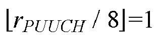 NRB is the number of PRBs in the target PUCCH resource, rPUUCH is the index of the target PUCCH resource,

- The terminal device of claim 45, 46 or 49, wherein the processing unit is specifically configured to:determine that PRB indexes of the target PUCCH resource in the first hop unit in the initial uplink BWP range from


 determine that the PRB indexes of the target PUCCH resource in the first hop unit in the initial uplink BWP range from


 NRB is the number of PRBs in the target PUCCH resource, rPUUCH is the index of the target PUCCH resource,


- The terminal device of any one of claims 43 to 50, wherein the processing unit is further configured to determine the target PUCCH resource from M PUCCH resources in a target PUCCH resource set, wherein M is a positive integer and M ≤ K, and K is the number of PUCCH resources in the target PUCCH resource set as defined in a protocol.
- The terminal device of claim 51, wherein the processing unit is further configured to determine the M PUCCH resources in the target PUCCH resource set according to at least one of: the number of PRBs in the target PUCCH resource, a PRB offset for the initial uplink BWP, the number of PRBs in the initial uplink BWP, or the number of initial CS indexes in a set of initial CS indexes.
- The terminal device of claim 52, wherein the processing unit is specifically configured to:determine that M is equal to RPUCCH, wherein

 NRB is the number of PRBs in the target PUCCH resource,

- The terminal device of claim 53, wherein the processing unit is specifically configured to:
determine first M PUCCH resources in the K PUCCH resources in the target PUCCH resource set that are defined in the protocol as the M PUCCH resources. - The terminal device of claim 54, wherein
when

- The terminal device of claim 54, wherein
the number of PRBs in each of the M PUCCH resources is NRB when RPUCCH = NCS *
- The terminal device of claim 52, wherein the processing unit is specifically configured to:determine that M is equal to RPUCCH, or, determine that M is RpUCCH+2 * NCS, wherein
 NRB is the number of PRBs in the target PUCCH resource,

- The terminal device of claim 57, wherein the processing unit is specifically configured to:
determine first M PUCCH resources in the K PUCCH resources in the target PUCCH resource set that are defined in the protocol as the M PUCCH resources. - The terminal device of claim 58, wherein the terminal device determines that M is equal to RPUCCH, and RPUCCH is further adjusted to be the multiple of 2 * NCS by rounding down the calculation result,when


 when
when


- The terminal device of claim 58, wherein
when the terminal device determines that M is RPUCCH +2 * NCS, and RPUCCH is further adjusted to be the multiple of 2 * NCS by rounding down the calculation result, the number of PRBs in each of PUCCH resources with resource indexes from 0 to R - NCS - 1 in the M PUCCH resources is NRB, the number of PRBs in each of PUCCH resources with resource indexes from R to RPUCCH+ NCS - 1 in the M PUCCH resources is NRB, the number of PRBs in each of PUCCH resources with resource indexes from R - NCS to R - 1 in the M PUCCH resources is

- The terminal device of claim 57, wherein the processing unit is specifically configured to:
determine that the M PUCCH resources comprise: first M/2 PUCCH resources in first K/2 PUCCH resources in the K PUCCH resources in the target PUCCH resource set that are defined in the protocol, and first M/2 PUCCH resources in last K/2 PUCCH resources in the K PUCCH resources in the target PUCCH resource set that are defined in the protocol. - The terminal device of claim 61, wherein
when the terminal device determines that M is RPUCCH +2 * NCS, and RPUCCH is further adjusted to be the multiple of 2 * NCS by rounding down the calculation result, the number of PRBs in each of PUCCH resources with resource indexes from 0 to RPUCCH /2 - 1 in the M PUCCH resources is NRB, the number of PRBs in each of PUCCH resources with resource indexes from K/2 to K/2 +RPUCCH /2 - 1 in the M PUCCH resources is NRB, the number of PRBs in each of PUCCH resources with resource indexes from RPUCCH /2 to RPUCCH /2 + NCS - 1 in the M PUCCH resources is

- The terminal device of any one of claims 57 to 59 and 61, wherein the number of PRBs in each of the M PUCCH resources is NRB when the terminal device determines that M is equal to RPUCCH and RPUCCH is further adjusted to be the multiple of 2 * NCS by rounding down the calculation result.
- The terminal device of claim 51, wherein a value of M is pre-configured or specified in the protocol.
- The terminal device of claim 64, wherein different initial uplink BWPs correspond to different values of M, respectively.
- The terminal device of claim 51, wherein a value of M is configured by a network device via system information.
- The terminal device of claim 66, wherein different PUCCH-resource-number indexes correspond to different values of M, respectively, wherein the PUCCH-resource-number index indicates the number of PUCCH resources in the target PUCCH resource set.
- The terminal device of claim 51, wherein a value of M is indicated by a network device via at least one bit in a PUCCH resource indicator field in downlink scheduling signaling.
- The terminal device of any one of claims 51 to 68, wherein the target PUCCH resource set contains a plurality of first symbols, and/or, the target PUCCH resource set contains a plurality of orthogonal cover codes (OCCs).
- The terminal device of claim 69, wherein
the target PUCCH resource set contains the plurality of first symbols, the number of the plurality of first symbols is L, and in each of the plurality of first symbols transmission of
- The terminal device of claim 69, wherein
the target PUCCH resource set contains the plurality of OCCs, the number of the plurality of OCCs is S, and in each of the first symbols transmission of
- The terminal device of any one of claims 43 to 71, wherein the target PUCCH resource is a common PUCCH resource configured for a terminal device in an unconnected state.
- The terminal device of any one of claims 43 to 72, wherein the processing unit is further configured to determine an index of the target PUCCH resource from a target PUCCH resource set according to the following formula:

rPUCCH is the index of the target PUCCH resource, NCCE is the number of control channel elements (CCEs) in a control resource set (CORESET) for reception of downlink scheduling signaling by the terminal device, n CCE,0 is an index of a first CCE for reception of the downlink scheduling signaling by the terminal device, and Δ PRI is a value of a PUCCH resource indicator field in the downlink scheduling signaling. - The terminal device of any one of claims 43 to 73, wherein a format of the PUCCH comprises one of: PUCCH format 0, PUCCH format 1, and PUCCH format 4.
- A network device, comprising:a communication unit configured to transmit indication information to a terminal device, the indication information indicating M PUCCH resources in a target physical uplink control channel (PUCCH) resource set, the M PUCCH resources comprising a target PUCCH resource, the target PUCCH resource comprising at least one physical resource block (PRB) per hop unit, M being a positive integer and M ≤ K, and K being the number of PUCCH resources in a PUCCH resource set as defined in a protocol; andthe communication unit being further configured to receive a PUCCH transmitted on the target PUCCH resource by the terminal device.
- The network device of claim 75, wherein different initial uplink bandwidth parts (BWPs) correspond to different values of M, respectively.
- The network device of claim 75, wherein the indication information is transmitted via system information.
- The network device of claim 77, wherein different PUCCH-resource-number indexes correspond to different values of M, respectively, wherein the PUCCH-resource-number index indicates the number of PUCCH resources in the target PUCCH resource set.
- The network device of claim 75, wherein the indication information is at least one bit in a PUCCH resource indicator field in downlink scheduling signaling.
- The network device of any one of claims 75 to 79, wherein the target PUCCH resource set contains a plurality of first symbols, and/or, the target PUCCH resource set contains a plurality of orthogonal cover codes (OCCs).
- The network device of claim 80, wherein
the target PUCCH resource set contains the plurality of first symbols, the number of the plurality of first symbols is L, and in each of the plurality of first symbols transmission of
- The network device of claim 80, wherein
the target PUCCH resource set contains the plurality of OCCs, the number of the plurality of OCCs is S, and in each of the first symbols transmission of
- The network device of any one of claims 75 to 82, wherein the target PUCCH resource is a common PUCCH resource configured for a terminal device in an unconnected state.
- The network device of any one of claims 75 to 83, wherein a format of the PUCCH comprises one of: PUCCH format 0, PUCCH format 1, and PUCCH format 4.
- A terminal device, comprising a processor and a memory, wherein the memory is configured to store a computer program, and the processor is configured to invoke and execute the computer program stored in the memory, to perform the method of any one of claims 1 to 32.
- A network device, comprising a processor and a memory, wherein the memory is configured to store a computer program, and the processor is configured to invoke and execute the computer program stored in the memory, to perform the method of any one of claims 33 to 42.
- A chip, comprising a processor, wherein the processor is configured to invoke and execute a computer program stored in a memory, to cause a device equipped with the chip to perform the method of any one of claims 1 to 32.
- A chip, comprising a processor, wherein the processor is configured to invoke and execute a computer program stored in a memory, to cause a device equipped with the chip to perform the method of any one of claims 33 to 42.
- A computer-readable storage medium configured to store a computer program which is operable with a computer to perform the method of any one of claims 1 to 32.
- A computer-readable storage medium configured to store a computer program which is operable with a computer to perform the method of any one of claims 33 to 42.
- A computer program product comprising computer program instructions which are operable with a computer to perform the method of any one of claims 1 to 32.
- A computer program product comprising computer program instructions which are operable with a computer to perform the method of any one of claims 33 to 42.
- A computer program being operable with a computer to perform the method of any one of claims 1 to 32.
- A computer program being operable with a computer to perform the method of any one of claims 33 to 42.
Applications Claiming Priority (1)
| Application Number | Priority Date | Filing Date | Title |
|---|---|---|---|
| PCT/CN2021/103442 WO2023272562A1 (en) | 2021-06-30 | 2021-06-30 | Wireless communication method, terminal device, and network device |
Publications (3)
| Publication Number | Publication Date |
|---|---|
| EP4319386A1 true EP4319386A1 (en) | 2024-02-07 |
| EP4319386A4 EP4319386A4 (en) | 2024-08-14 |
| EP4319386B1 EP4319386B1 (en) | 2025-04-30 |
Family
ID=84690925
Family Applications (1)
| Application Number | Title | Priority Date | Filing Date |
|---|---|---|---|
| EP21947516.7A Active EP4319386B1 (en) | 2021-06-30 | 2021-06-30 | Wireless communication method, terminal device, and network device |
Country Status (5)
| Country | Link |
|---|---|
| US (1) | US20240064749A1 (en) |
| EP (1) | EP4319386B1 (en) |
| CN (2) | CN117793910A (en) |
| ES (1) | ES3027235T3 (en) |
| WO (1) | WO2023272562A1 (en) |
Families Citing this family (1)
| Publication number | Priority date | Publication date | Assignee | Title |
|---|---|---|---|---|
| WO2025065644A1 (en) * | 2023-09-28 | 2025-04-03 | Zte Corporation | Systems and methods for capacity expansion of control channel |
Family Cites Families (4)
| Publication number | Priority date | Publication date | Assignee | Title |
|---|---|---|---|---|
| WO2019139436A1 (en) * | 2018-01-12 | 2019-07-18 | 엘지전자 주식회사 | Method for performing physical uplink control channel transmission in wireless communication system and terminal using method |
| WO2020146643A1 (en) * | 2019-01-10 | 2020-07-16 | Apple Inc. | Resource allocation for physical uplink control channel during initial access in nr-unlicensed |
| CN112242892B (en) * | 2019-07-19 | 2022-02-08 | 大唐移动通信设备有限公司 | Resource allocation method and device for physical uplink control channel |
| CN111901870B (en) * | 2020-03-25 | 2025-02-14 | 中兴通讯股份有限公司 | A transmission method, device, equipment and storage medium |
-
2021
- 2021-06-30 WO PCT/CN2021/103442 patent/WO2023272562A1/en not_active Ceased
- 2021-06-30 ES ES21947516T patent/ES3027235T3/en active Active
- 2021-06-30 CN CN202311848951.XA patent/CN117793910A/en active Pending
- 2021-06-30 EP EP21947516.7A patent/EP4319386B1/en active Active
- 2021-06-30 CN CN202180095194.6A patent/CN116982370A/en active Pending
-
2023
- 2023-10-27 US US18/496,433 patent/US20240064749A1/en active Pending
Also Published As
| Publication number | Publication date |
|---|---|
| CN116982370A (en) | 2023-10-31 |
| WO2023272562A1 (en) | 2023-01-05 |
| US20240064749A1 (en) | 2024-02-22 |
| EP4319386A4 (en) | 2024-08-14 |
| ES3027235T3 (en) | 2025-06-13 |
| CN117793910A (en) | 2024-03-29 |
| EP4319386B1 (en) | 2025-04-30 |
Similar Documents
| Publication | Publication Date | Title |
|---|---|---|
| US12610383B2 (en) | Physical sidelink feedback channel (PSFCH) transmission method and terminal device | |
| US20240276472A1 (en) | Method for resource indication, terminal device, and network device | |
| US20240073910A1 (en) | Wireless communication method and terminal device | |
| US20240023076A1 (en) | Method for channel estimation, terminal device, and network device | |
| US20240276527A1 (en) | Wireless communication method, first terminal device, and second terminal device | |
| US20230209516A1 (en) | Method for determining sidelink configured grant resource, and terminal device | |
| EP4498623B1 (en) | Transmission method, terminal device, and network device | |
| US20230422240A1 (en) | Wireless communication method, terminal device, and network device | |
| US20240064749A1 (en) | Method for wireless communication, terminal device, and network device | |
| EP4266775B1 (en) | Wireless communication method and terminal device | |
| US20240323904A1 (en) | Wireless communication method and terminal device | |
| EP4270831A1 (en) | Method and device for repeatedly transmitting data channel | |
| US20230224908A1 (en) | Method for repeatedly transmitting control channel, terminal device, and network device | |
| WO2023108638A1 (en) | Wireless communication method, terminal device, and network device | |
| US20250317712A1 (en) | Wireless communication method, terminal device, and network device | |
| EP4657945A1 (en) | Resource indication method, terminal device, and network device | |
| US20260020060A1 (en) | Communication method and terminal | |
| US20240340908A1 (en) | Wireless communication method, terminal device, and network device | |
| US20240334444A1 (en) | Method for wireless communication, terminal device, and network device | |
| US20250142597A1 (en) | Sidelink transmission method and terminal | |
| WO2025065152A9 (en) | Sidelink communication method, and terminal |
Legal Events
| Date | Code | Title | Description |
|---|---|---|---|
| STAA | Information on the status of an ep patent application or granted ep patent |
Free format text: STATUS: THE INTERNATIONAL PUBLICATION HAS BEEN MADE |
|
| PUAI | Public reference made under article 153(3) epc to a published international application that has entered the european phase |
Free format text: ORIGINAL CODE: 0009012 |
|
| STAA | Information on the status of an ep patent application or granted ep patent |
Free format text: STATUS: REQUEST FOR EXAMINATION WAS MADE |
|
| 17P | Request for examination filed |
Effective date: 20231026 |
|
| AK | Designated contracting states |
Kind code of ref document: A1 Designated state(s): AL AT BE BG CH CY CZ DE DK EE ES FI FR GB GR HR HU IE IS IT LI LT LU LV MC MK MT NL NO PL PT RO RS SE SI SK SM TR |
|
| REG | Reference to a national code |
Ref country code: DE Free format text: PREVIOUS MAIN CLASS: H04W0072040000 Ref country code: DE Ref legal event code: R079 Ref document number: 602021030198 Country of ref document: DE Free format text: PREVIOUS MAIN CLASS: H04W0072040000 Ipc: H04L0005000000 |
|
| RIC1 | Information provided on ipc code assigned before grant |
Ipc: H04W 72/21 20230101ALI20240416BHEP Ipc: H04L 5/00 20060101AFI20240416BHEP |
|
| A4 | Supplementary search report drawn up and despatched |
Effective date: 20240715 |
|
| RIC1 | Information provided on ipc code assigned before grant |
Ipc: H04W 72/21 20230101ALI20240709BHEP Ipc: H04L 5/00 20060101AFI20240709BHEP |
|
| DAV | Request for validation of the european patent (deleted) | ||
| DAX | Request for extension of the european patent (deleted) | ||
| GRAP | Despatch of communication of intention to grant a patent |
Free format text: ORIGINAL CODE: EPIDOSNIGR1 |
|
| STAA | Information on the status of an ep patent application or granted ep patent |
Free format text: STATUS: GRANT OF PATENT IS INTENDED |
|
| INTG | Intention to grant announced |
Effective date: 20250130 |
|
| GRAS | Grant fee paid |
Free format text: ORIGINAL CODE: EPIDOSNIGR3 |
|
| GRAA | (expected) grant |
Free format text: ORIGINAL CODE: 0009210 |
|
| STAA | Information on the status of an ep patent application or granted ep patent |
Free format text: STATUS: THE PATENT HAS BEEN GRANTED |
|
| AK | Designated contracting states |
Kind code of ref document: B1 Designated state(s): AL AT BE BG CH CY CZ DE DK EE ES FI FR GB GR HR HU IE IS IT LI LT LU LV MC MK MT NL NO PL PT RO RS SE SI SK SM TR |
|
| REG | Reference to a national code |
Ref country code: CH Ref legal event code: EP Ref country code: GB Ref legal event code: FG4D |
|
| REG | Reference to a national code |
Ref country code: DE Ref legal event code: R096 Ref document number: 602021030198 Country of ref document: DE |
|
| REG | Reference to a national code |
Ref country code: IE Ref legal event code: FG4D |
|
| REG | Reference to a national code |
Ref country code: NL Ref legal event code: FP |
|
| REG | Reference to a national code |
Ref country code: ES Ref legal event code: FG2A Ref document number: 3027235 Country of ref document: ES Kind code of ref document: T3 Effective date: 20250613 |
|
| PGFP | Annual fee paid to national office [announced via postgrant information from national office to epo] |
Ref country code: DE Payment date: 20250625 Year of fee payment: 5 |
|
| PGFP | Annual fee paid to national office [announced via postgrant information from national office to epo] |
Ref country code: GB Payment date: 20250620 Year of fee payment: 5 |
|
| PGFP | Annual fee paid to national office [announced via postgrant information from national office to epo] |
Ref country code: NL Payment date: 20250619 Year of fee payment: 5 |
|
| PGFP | Annual fee paid to national office [announced via postgrant information from national office to epo] |
Ref country code: FR Payment date: 20250620 Year of fee payment: 5 |
|
| REG | Reference to a national code |
Ref country code: AT Ref legal event code: MK05 Ref document number: 1791097 Country of ref document: AT Kind code of ref document: T Effective date: 20250430 |
|
| P01 | Opt-out of the competence of the unified patent court (upc) registered |
Free format text: CASE NUMBER: UPC_APP_5331_4319386/2025 Effective date: 20250829 |
|
| PG25 | Lapsed in a contracting state [announced via postgrant information from national office to epo] |
Ref country code: FI Free format text: LAPSE BECAUSE OF FAILURE TO SUBMIT A TRANSLATION OF THE DESCRIPTION OR TO PAY THE FEE WITHIN THE PRESCRIBED TIME-LIMIT Effective date: 20250430 Ref country code: PT Free format text: LAPSE BECAUSE OF FAILURE TO SUBMIT A TRANSLATION OF THE DESCRIPTION OR TO PAY THE FEE WITHIN THE PRESCRIBED TIME-LIMIT Effective date: 20250901 |
|
| PGFP | Annual fee paid to national office [announced via postgrant information from national office to epo] |
Ref country code: ES Payment date: 20250702 Year of fee payment: 5 |
|
| REG | Reference to a national code |
Ref country code: LT Ref legal event code: MG9D |
|
| PG25 | Lapsed in a contracting state [announced via postgrant information from national office to epo] |
Ref country code: NO Free format text: LAPSE BECAUSE OF FAILURE TO SUBMIT A TRANSLATION OF THE DESCRIPTION OR TO PAY THE FEE WITHIN THE PRESCRIBED TIME-LIMIT Effective date: 20250730 Ref country code: GR Free format text: LAPSE BECAUSE OF FAILURE TO SUBMIT A TRANSLATION OF THE DESCRIPTION OR TO PAY THE FEE WITHIN THE PRESCRIBED TIME-LIMIT Effective date: 20250731 |
|
| PG25 | Lapsed in a contracting state [announced via postgrant information from national office to epo] |
Ref country code: PL Free format text: LAPSE BECAUSE OF FAILURE TO SUBMIT A TRANSLATION OF THE DESCRIPTION OR TO PAY THE FEE WITHIN THE PRESCRIBED TIME-LIMIT Effective date: 20250430 |
|
| PGFP | Annual fee paid to national office [announced via postgrant information from national office to epo] |
Ref country code: IT Payment date: 20250619 Year of fee payment: 5 |
|
| PG25 | Lapsed in a contracting state [announced via postgrant information from national office to epo] |
Ref country code: BG Free format text: LAPSE BECAUSE OF FAILURE TO SUBMIT A TRANSLATION OF THE DESCRIPTION OR TO PAY THE FEE WITHIN THE PRESCRIBED TIME-LIMIT Effective date: 20250430 |
|
| PG25 | Lapsed in a contracting state [announced via postgrant information from national office to epo] |
Ref country code: HR Free format text: LAPSE BECAUSE OF FAILURE TO SUBMIT A TRANSLATION OF THE DESCRIPTION OR TO PAY THE FEE WITHIN THE PRESCRIBED TIME-LIMIT Effective date: 20250430 |
|
| PG25 | Lapsed in a contracting state [announced via postgrant information from national office to epo] |
Ref country code: AT Free format text: LAPSE BECAUSE OF FAILURE TO SUBMIT A TRANSLATION OF THE DESCRIPTION OR TO PAY THE FEE WITHIN THE PRESCRIBED TIME-LIMIT Effective date: 20250430 |
|
| PG25 | Lapsed in a contracting state [announced via postgrant information from national office to epo] |
Ref country code: RS Free format text: LAPSE BECAUSE OF FAILURE TO SUBMIT A TRANSLATION OF THE DESCRIPTION OR TO PAY THE FEE WITHIN THE PRESCRIBED TIME-LIMIT Effective date: 20250731 |
|
| PG25 | Lapsed in a contracting state [announced via postgrant information from national office to epo] |
Ref country code: IS Free format text: LAPSE BECAUSE OF FAILURE TO SUBMIT A TRANSLATION OF THE DESCRIPTION OR TO PAY THE FEE WITHIN THE PRESCRIBED TIME-LIMIT Effective date: 20250830 |
|
| PG25 | Lapsed in a contracting state [announced via postgrant information from national office to epo] |
Ref country code: LV Free format text: LAPSE BECAUSE OF FAILURE TO SUBMIT A TRANSLATION OF THE DESCRIPTION OR TO PAY THE FEE WITHIN THE PRESCRIBED TIME-LIMIT Effective date: 20250430 |
|
| PG25 | Lapsed in a contracting state [announced via postgrant information from national office to epo] |
Ref country code: SM Free format text: LAPSE BECAUSE OF FAILURE TO SUBMIT A TRANSLATION OF THE DESCRIPTION OR TO PAY THE FEE WITHIN THE PRESCRIBED TIME-LIMIT Effective date: 20250430 Ref country code: DK Free format text: LAPSE BECAUSE OF FAILURE TO SUBMIT A TRANSLATION OF THE DESCRIPTION OR TO PAY THE FEE WITHIN THE PRESCRIBED TIME-LIMIT Effective date: 20250430 |
|
| PG25 | Lapsed in a contracting state [announced via postgrant information from national office to epo] |
Ref country code: CZ Free format text: LAPSE BECAUSE OF FAILURE TO SUBMIT A TRANSLATION OF THE DESCRIPTION OR TO PAY THE FEE WITHIN THE PRESCRIBED TIME-LIMIT Effective date: 20250430 |
|
| PG25 | Lapsed in a contracting state [announced via postgrant information from national office to epo] |
Ref country code: EE Free format text: LAPSE BECAUSE OF FAILURE TO SUBMIT A TRANSLATION OF THE DESCRIPTION OR TO PAY THE FEE WITHIN THE PRESCRIBED TIME-LIMIT Effective date: 20250430 |
|
| PG25 | Lapsed in a contracting state [announced via postgrant information from national office to epo] |
Ref country code: SK Free format text: LAPSE BECAUSE OF FAILURE TO SUBMIT A TRANSLATION OF THE DESCRIPTION OR TO PAY THE FEE WITHIN THE PRESCRIBED TIME-LIMIT Effective date: 20250430 |
|
| REG | Reference to a national code |
Ref country code: CH Ref legal event code: H13 Free format text: ST27 STATUS EVENT CODE: U-0-0-H10-H13 (AS PROVIDED BY THE NATIONAL OFFICE) Effective date: 20260127 |
|
| PG25 | Lapsed in a contracting state [announced via postgrant information from national office to epo] |
Ref country code: MC Free format text: LAPSE BECAUSE OF FAILURE TO SUBMIT A TRANSLATION OF THE DESCRIPTION OR TO PAY THE FEE WITHIN THE PRESCRIBED TIME-LIMIT Effective date: 20250430 |
|
| REG | Reference to a national code |
Ref country code: DE Ref legal event code: R097 Ref document number: 602021030198 Country of ref document: DE |
|
| PG25 | Lapsed in a contracting state [announced via postgrant information from national office to epo] |
Ref country code: LU Free format text: LAPSE BECAUSE OF NON-PAYMENT OF DUE FEES Effective date: 20250630 |
|
| REG | Reference to a national code |
Ref country code: BE Ref legal event code: MM Effective date: 20250630 |
|
| PG25 | Lapsed in a contracting state [announced via postgrant information from national office to epo] |
Ref country code: RO Free format text: LAPSE BECAUSE OF FAILURE TO SUBMIT A TRANSLATION OF THE DESCRIPTION OR TO PAY THE FEE WITHIN THE PRESCRIBED TIME-LIMIT Effective date: 20250430 |
|
| PLBE | No opposition filed within time limit |
Free format text: ORIGINAL CODE: 0009261 |
|
| STAA | Information on the status of an ep patent application or granted ep patent |
Free format text: STATUS: NO OPPOSITION FILED WITHIN TIME LIMIT |
|
| REG | Reference to a national code |
Ref country code: CH Ref legal event code: L10 Free format text: ST27 STATUS EVENT CODE: U-0-0-L10-L00 (AS PROVIDED BY THE NATIONAL OFFICE) Effective date: 20260311 |
|
| 26N | No opposition filed |
Effective date: 20260202 |
|
| PG25 | Lapsed in a contracting state [announced via postgrant information from national office to epo] |
Ref country code: IE Free format text: LAPSE BECAUSE OF NON-PAYMENT OF DUE FEES Effective date: 20250630 |
|
| PG25 | Lapsed in a contracting state [announced via postgrant information from national office to epo] |
Ref country code: BE Free format text: LAPSE BECAUSE OF NON-PAYMENT OF DUE FEES Effective date: 20250630 |
|
| PG25 | Lapsed in a contracting state [announced via postgrant information from national office to epo] |
Ref country code: CH Free format text: LAPSE BECAUSE OF NON-PAYMENT OF DUE FEES Effective date: 20250630 |