EP4319384A1 - Terminal capability reporting method, user terminal and communication system - Google Patents
Terminal capability reporting method, user terminal and communication system Download PDFInfo
- Publication number
- EP4319384A1 EP4319384A1 EP21939047.3A EP21939047A EP4319384A1 EP 4319384 A1 EP4319384 A1 EP 4319384A1 EP 21939047 A EP21939047 A EP 21939047A EP 4319384 A1 EP4319384 A1 EP 4319384A1
- Authority
- EP
- European Patent Office
- Prior art keywords
- frequency band
- switching
- band
- terminal capability
- uplink
- Prior art date
- Legal status (The legal status is an assumption and is not a legal conclusion. Google has not performed a legal analysis and makes no representation as to the accuracy of the status listed.)
- Pending
Links
Images

Classifications
-
- H—ELECTRICITY
- H04—ELECTRIC COMMUNICATION TECHNIQUE
- H04W—WIRELESS COMMUNICATION NETWORKS
- H04W8/00—Network data management
- H04W8/22—Processing or transfer of terminal data, e.g. status or physical capabilities
- H04W8/24—Transfer of terminal data
-
- H—ELECTRICITY
- H04—ELECTRIC COMMUNICATION TECHNIQUE
- H04W—WIRELESS COMMUNICATION NETWORKS
- H04W72/00—Local resource management
- H04W72/12—Wireless traffic scheduling
- H04W72/1263—Mapping of traffic onto schedule, e.g. scheduled allocation or multiplexing of flows
- H04W72/1268—Mapping of traffic onto schedule, e.g. scheduled allocation or multiplexing of flows of uplink data flows
-
- H—ELECTRICITY
- H04—ELECTRIC COMMUNICATION TECHNIQUE
- H04L—TRANSMISSION OF DIGITAL INFORMATION, e.g. TELEGRAPHIC COMMUNICATION
- H04L5/00—Arrangements affording multiple use of the transmission path
- H04L5/0001—Arrangements for dividing the transmission path
- H04L5/0003—Two-dimensional division
- H04L5/0005—Time-frequency
- H04L5/0007—Time-frequency the frequencies being orthogonal, e.g. OFDM(A) or DMT
- H04L5/001—Time-frequency the frequencies being orthogonal, e.g. OFDM(A) or DMT the frequencies being arranged in component carriers
-
- H—ELECTRICITY
- H04—ELECTRIC COMMUNICATION TECHNIQUE
- H04W—WIRELESS COMMUNICATION NETWORKS
- H04W36/00—Hand-off or reselection arrangements
- H04W36/0005—Control or signalling for completing the hand-off
- H04W36/0055—Transmission or use of information for re-establishing the radio link
-
- H—ELECTRICITY
- H04—ELECTRIC COMMUNICATION TECHNIQUE
- H04W—WIRELESS COMMUNICATION NETWORKS
- H04W72/00—Local resource management
- H04W72/04—Wireless resource allocation
- H04W72/044—Wireless resource allocation based on the type of the allocated resource
- H04W72/0453—Resources in frequency domain, e.g. a carrier in FDMA
-
- H—ELECTRICITY
- H04—ELECTRIC COMMUNICATION TECHNIQUE
- H04W—WIRELESS COMMUNICATION NETWORKS
- H04W72/00—Local resource management
- H04W72/50—Allocation or scheduling criteria for wireless resources
- H04W72/51—Allocation or scheduling criteria for wireless resources based on terminal or device properties
-
- H—ELECTRICITY
- H04—ELECTRIC COMMUNICATION TECHNIQUE
- H04W—WIRELESS COMMUNICATION NETWORKS
- H04W76/00—Connection management
- H04W76/20—Manipulation of established connections
Definitions
- the present disclosure relates to the field of communication technologies, and in particular, to a terminal capability reporting method, a user terminal, and a communication system.
- the Uplink Tx Switching technology in 3GPP (Third Generation Partnership Project) R16 (Release 16) is applicable for transmitter switching between two carriers.
- One of these two carriers is used for an uplink transmission with one antenna, and the other carrier is used for an uplink transmission with two antennas.
- a dual-carrier frequency band (such as, 3.5GHz) has a capability of uplink 2Tx, while a single carrier frequency band (such as 2.1/1.8GHz) has a capability of uplink 1Tx or uplink 2Tx.
- a terminal capability reporting method which is executed by a user terminal and comprises: reporting terminal capability information to a base station, wherein the terminal capability information comprises band pairs in a band combination supporting uplink transmitter (Tx) switching, and a switching time for each of the band pairs, wherein the each of the band pairs comprises a first frequency band and a second frequency band each comprising one or two carriers.
- Tx uplink transmitter
- the terminal capability information further comprises: a number of carriers within each frequency band of the each of the band pairs and a feature set of each of the carriers.
- the terminal capability information further comprises: indication information about whether a downlink interruption occurs on a frequency band in the band combination during uplink Tx switching on the each of the band pairs.
- an uplink 1Tx transmission is supported on the first frequency band, and an uplink 2Tx transmission is supported on the second frequency band.
- the terminal capability information further comprises: a first switching option supported by the band combination in case of switching for carrier aggregation, wherein the first switching option comprises one of 2Tx is used for an uplink transmission on the first frequency band, or both of 2Tx is used for an uplink transmission on the second frequency band.
- the terminal capability information further comprises: a second switching option supported by the band combination in case of switching for carrier aggregation, wherein the second switching option comprises one of 2Tx is used for an uplink transmission on the first frequency band and the other one of the 2Tx is used for an uplink transmission on the second frequency band, or both of 2Tx is used for an uplink transmission on the second frequency band.
- an uplink 2Tx transmission is supported on both the first frequency band and the second frequency band.
- the terminal capability information further comprises: a first switching option supported by the band combination in case of switching for carrier aggregation, wherein the first switching option comprises both of 2Tx is used for an uplink transmission on the first frequency band or the second frequency band.
- the terminal capability information further comprises: a second switching option supported by the band combinations in case of switching for carrier aggregation, wherein the second switching option comprises both of 2Tx is used for an uplink transmission on the first frequency band or the second frequency band, or one of 2Tx is used for an uplink transmission on the first frequency band and the other one of the 2Tx is used for an uplink transmission on the second frequency band.
- the switching time is 35 ⁇ s, 140 ⁇ s, or 210 ⁇ s.
- a user terminal comprising: a processor; a memory coupled to the processor for storing instructions, which when executed by the processor, cause the processor to execute the terminal capability reporting method according to any one of foregoing embodiments.
- a communication system comprising: a user terminal according to any one of the above embodiments; and a base station used for send a radio resource control (RRC) message to the user terminal based on the terminal capability information reported by the user terminal, wherein the RRC message comprises configuration information on whether a Tx switching period is configured in one or more specific carriers.
- RRC radio resource control
- the Tx switching period is set to a same configuration for carriers on a same frequency band.
- the Tx switching period configured on one or more specific carriers on the first frequency band is true, the Tx switching period configured on one or more specific carriers on the second frequency band is false or if the Tx switching period configured on one or more specific carriers on the first frequency band is false, the Tx switching period configured on one or more specific carriers in the second frequency band is true.
- the RRC message in case of switching for carrier aggregation, if the user terminal operates in a multi-carrier Tx switching mode, the RRC message further comprises configuration information for configuring the user terminal with a first switching option or a second switching option.
- the RRC message further comprises configuration information for a first carrier on the first frequency band, and configuration information for a second carrier on the second frequency band and configuration information for a third carrier on the second frequency band, wherein the uplink 1Tx transmission is used on the first carrier, and the uplink 2Tx transmission is used on the second carrier and the third carrier.
- the RRC message does not comprise configuration information for a first carrier on the first frequency band, configuration information for a second carrier on the second frequency band or configuration information for a third carrier on the second frequency band.
- a computer-readable storage medium storing computer instructions that, when executed by a processor, implement the terminal capability reporting method of any one of the above embodiments.
- a word such as “include” or “comprise” used in the present disclosure means that the element before the word covers the elements listed after the word, without excluding the possibility of also covering other elements.
- the inventors have found through research that a Tx switching scheme currently used in the uplink Tx switching technology in 3GPP R16 is only applicable for a Tx switching between carriers within a single frequency band, and is not applicable for a Tx switching across frequency bands, which cannot effectively improve an utilization of an uplink bandwidth.
- this disclosure provides a terminal capability reporting scheme that can effectively improve the utilization of the uplink bandwidth.
- FIG. 1 is a flowchart of a terminal capability reporting method according to some embodiments of the present disclosure. In some embodiments, the steps of the following terminal capability reporting method are executed by a user terminal.
- step 101 terminal capability information is obtained.
- the terminal capability information comprises various band pairs in a band combination supporting uplink Tx switching, and a switching time for each of the band pairs.
- the each of the band pairs comprises a first frequency band and a second frequency band each comprising one or two carriers.
- the first frequency band comprises one carrier used for an uplink 1Tx transmission or an uplink 2Tx transmission
- the second frequency band comprises two carriers used for an uplink 2Tx transmission.
- the switching time of the each of the band pairs is 35 ⁇ s, 140 ⁇ s, or 210 ⁇ s.
- the switching time of the each of the band pairs indicates a time required for a Tx switching from one frequency band to another frequency band in the each of the band pairs.
- the switching times can be the same or different for different numbers of carriers, providing flexibility in implementation.
- the terminal capability information further comprises: a number of carriers within each frequency band of the each of the band pairs (ca-BandwidthClassUL parameter) and a feature set of each of the carriers (per cc feature set).
- a user terminal supporting a Tx switching among N (N ⁇ 3) carriers supports a Tx switching among N-1 carriers.
- the terminal capability information further comprises: indication information about whether a downlink interruption on a frequency band in the band combination is caused by an uplink Tx switching on the each of the band pairs.
- the indication information comprises: for the each of the band pairs, whether the downlink interruption is required on each of the frequency bands in the band combination.
- an uplink 1Tx transmission is supported on the first frequency band, and an uplink 2Tx transmission is supported on the second frequency band, which corresponds to a 1Tx-2Tx scenario.
- the terminal capability information further comprises: a first switching option supported by the band combination in case of switching for carrier aggregation.
- the first switching option is shown in Table 1.
- Table 1 Case 1 1T + 0T Case 2: 0T + 2T
- the terminal capability information further comprises: a second switching option supported by the band combination in case of switching for carrier aggregation.
- one of 2Tx is used for an uplink transmission on the first frequency band and the other one of the 2Tx is used for an uplink transmission on the second frequency band.
- both of the 2Tx are used for an uplink transmission on the second frequency band.
- an uplink 2Tx transmission is supported on both the first frequency band and the second frequency band, which corresponds to a 2Tx-2Tx scenario.
- the terminal capability information further comprises: a first switching option supported by the band combination in case of switching for carrier aggregation.
- both of 2Tx is used for an uplink transmission on the second frequency band.
- both of 2Tx are used for an uplink transmission the first frequency band.
- the terminal capability information further comprises: a second switching option supported by the band combinations in case of switching for carrier aggregation.
- one of the 2Tx is used for an uplink transmission on the first frequency band
- the other one of 2Tx is used for an uplink transmission on the second frequency band.
- both of 2Tx are used for an uplink transmission on the second frequency band.
- both of the 2Tx are used for an uplink transmission on the first frequency band.
- power classes of switching frequency bands and band combinations may be different. For example, a newly reported power class can be used for options 1 and 2, while an original power class can be used for option 3.
- the terminal capability information is processed using a UE capability filter.
- step 102 the terminal capability information is reported to a base station.
- the base station by reporting the each of the band pairs supporting uplink Tx switching in the band combination, and the switching time for the each of the band pairs to the base station, the base station can configure a user terminal to switch between the frequency bands based on the received terminal capability information, thereby effectively improving an utilization of an uplink bandwidth.
- FIG. 2 is a schematic structural diagram of a user terminal according to some embodiments of the present disclosure. As shown in FIG. 3 , the user terminal comprises a memory 21 and a processor 22.
- the memory 21 is used for storing instructions.
- the processor 22 is coupled to the memory 21.
- the processor 22 is configured to, based on instructions stored in the memory, carry out a method to implement the embodiment shown in FIG. 1 .
- the user terminal also comprises a communication interface 23 for information interaction with other devices.
- the user terminal further comprises a bus 24.
- the processor 22, the communication interface 23, and the memory 21 perform communication with each other through the bus 24.
- the memory 21 may comprise high-speed RAM (Random Access Memory) or NVM (Non-Volatile Memory). For example, it may be at least one disk storage.
- the memory 21 may also be a memory array.
- the memory 21 may also be partitioned into blocks, which may be combined into virtual volumes according to a certain rule.
- processor 22 may be a central processing unit (CPU), or may be an Application Specific Integrated Circuit (ASIC) or one or more integrated circuits configured to implement the embodiments of the present disclosure.
- CPU central processing unit
- ASIC Application Specific Integrated Circuit
- the present disclosure further provides a computer-readable medium stored thereon computer instructions that, when executed by a processor, implement a method involved in the embodiments of FIG. 1 .
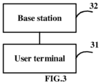
- FIG. 3 is a schematic structural diagram of a communication system according to some embodiments of the present disclosure.
- the communication system comprises a user terminal 31 and a base station 32.
- the user terminal 31 is a user terminal involved in any embodiment of FIG. 2 .
- the base station 32 is configured to send a RRC (Radio Resource Control) message to the user terminal based on the terminal capability information reported by the user terminal, wherein the RRC message comprises configuration information on whether a Tx switching period is configured in one or more specific carriers.
- RRC Radio Resource Control
- the Tx switching period is set to a same configuration for carriers on a same frequency band.
- the Tx switching period is configured on one or more specific carriers in one of the first frequency band and the second frequency band.
- the second frequency band is configured with FALSE.
- the user terminal cannot send uplink signals in a Tx switching period.
- the RRC message in case of switching for carrier aggregation, if the user terminal operates in a multi-carrier Tx switching mode, the RRC message further comprises configuration information for configuring the user terminal with a first switching option or a second switching option.
- the RRC message further comprises configuration information for a first carrier on the first frequency band, and configuration information for a second carrier on the second frequency band and configuration information for a third carrier on the second frequency band, wherein the uplink 1Tx transmission is used on the first carrier, and the uplink 2Tx transmission is used on the second carrier and the third carrier.
- one carrier on a first frequency band used for an uplink 1Tx transmission is configured as a first carrier
- two carriers on a second frequency band used for an uplink 2Tx transmission are configured as a second carrier and a third carrier.
- the RRC message does not comprise configuration information for a first carrier on the first frequency band, configuration information for a second carrier on the second frequency band or configuration information for a third carrier on the second frequency band.
- an uplink 2Tx transmission can be used on all the carriers in the first frequency band and the second frequency band, there is no need to configure which carrier is used as the first carrier, which carrier is used as the second carrier, and which carrier is used as the third carrier.
- the above functional modules can be implemented as a general-purpose processor, a Programmable logic controller (PLC), a digital signal processor (DSP), an application specific integrated circuit (ASIC), a field programmable gate array (FPGA) or other programmable logic devices, discrete gates or transistor logic devices, discrete hardware components or any appropriate combination thereof for performing the functions described in this application.
- PLC Programmable logic controller
- DSP digital signal processor
- ASIC application specific integrated circuit
- FPGA field programmable gate array
- embodiments of the present disclosure may be provided as a method, a system, or a computer program product. Therefore, embodiments of the present disclosure can take the form of an entirely hardware embodiment, an entirely software embodiment or an embodiment containing both hardware and software elements. Moreover, the present disclosure may take the form of a computer program product embodied on one or more computer-usable non-transitory storage media (comprising but not limited to disk storage, CD-ROM, optical storage device, etc.) having computer-usable program code embodied therein.
- computer-usable non-transitory storage media comprising but not limited to disk storage, CD-ROM, optical storage device, etc.
- the present disclosure is described with reference to flowcharts and/or block diagrams of methods, apparatuses (systems) and computer program products according to embodiments of the present disclosure. It should be understood that each process and/or block in the flowcharts and/or block diagrams, and combinations of the processes and/or blocks in the flowcharts and/or block diagrams may be implemented by computer program instructions.
- the computer program instructions may be provided to a processor of a general purpose computer, a special purpose computer, an embedded processor, or other programmable data processing device to generate a machine such that the instructions executed by a processor of a computer or other programmable data processing device to generate means implementing the functions specified in one or more flows of the flowcharts and/or one or more blocks of the block diagrams.
- the computer program instructions may also be stored in a computer readable storage device capable of directing a computer or other programmable data processing apparatus to operate in a specific manner such that the instructions stored in the computer readable storage device produce an article of manufacture comprising instruction means implementing the functions specified in one or more flows of the flowcharts and/or one or more blocks of the block diagrams.
Landscapes
- Engineering & Computer Science (AREA)
- Signal Processing (AREA)
- Computer Networks & Wireless Communication (AREA)
- Databases & Information Systems (AREA)
- Mobile Radio Communication Systems (AREA)
Abstract
Description
- The present disclosure is based on and claims priority of
Chinese application for invention No. 202110466312.1, filed on Apr. 28, 2021 - The present disclosure relates to the field of communication technologies, and in particular, to a terminal capability reporting method, a user terminal, and a communication system.
- The Uplink Tx Switching technology in 3GPP (Third Generation Partnership Project) R16 (Release 16) is applicable for transmitter switching between two carriers. One of these two carriers is used for an uplink transmission with one antenna, and the other carrier is used for an uplink transmission with two antennas.
- At present, in a co-construction and sharing project based on China Telecom and China Unicom, there is 200-300MHz frequency spectrum in the 3.5GHz band, i.e., two component carriers, and one component carrier in another FDD (Frequency Division Duplex) frequency band (such as, the 2.1GHz or 1.8GHz band). A dual-carrier frequency band (such as, 3.5GHz) has a capability of uplink 2Tx, while a single carrier frequency band (such as 2.1/1.8GHz) has a capability of uplink 1Tx or uplink 2Tx.
- According to a first aspect of the embodiments of the present disclosure, there is provided a terminal capability reporting method, which is executed by a user terminal and comprises: reporting terminal capability information to a base station, wherein the terminal capability information comprises band pairs in a band combination supporting uplink transmitter (Tx) switching, and a switching time for each of the band pairs, wherein the each of the band pairs comprises a first frequency band and a second frequency band each comprising one or two carriers.
- In some embodiments, the terminal capability information further comprises: a number of carriers within each frequency band of the each of the band pairs and a feature set of each of the carriers.
- In some embodiments, the terminal capability information further comprises: indication information about whether a downlink interruption occurs on a frequency band in the band combination during uplink Tx switching on the each of the band pairs.
- In some embodiments, an uplink 1Tx transmission is supported on the first frequency band, and an uplink 2Tx transmission is supported on the second frequency band.
- In some embodiments, the terminal capability information further comprises: a first switching option supported by the band combination in case of switching for carrier aggregation, wherein the first switching option comprises one of 2Tx is used for an uplink transmission on the first frequency band, or both of 2Tx is used for an uplink transmission on the second frequency band.
- In some embodiments, the terminal capability information further comprises: a second switching option supported by the band combination in case of switching for carrier aggregation, wherein the second switching option comprises one of 2Tx is used for an uplink transmission on the first frequency band and the other one of the 2Tx is used for an uplink transmission on the second frequency band, or both of 2Tx is used for an uplink transmission on the second frequency band.
- In some embodiments, an uplink 2Tx transmission is supported on both the first frequency band and the second frequency band.
- In some embodiments, the terminal capability information further comprises: a first switching option supported by the band combination in case of switching for carrier aggregation, wherein the first switching option comprises both of 2Tx is used for an uplink transmission on the first frequency band or the second frequency band.
- In some embodiments, the terminal capability information further comprises: a second switching option supported by the band combinations in case of switching for carrier aggregation, wherein the second switching option comprises both of 2Tx is used for an uplink transmission on the first frequency band or the second frequency band, or one of 2Tx is used for an uplink transmission on the first frequency band and the other one of the 2Tx is used for an uplink transmission on the second frequency band.
- In some embodiments, the switching time is 35 µs, 140 µs, or 210 µs.
- According to a second aspect of the embodiments of the present disclosure, there is provided a user terminal, comprising: a processor; a memory coupled to the processor for storing instructions, which when executed by the processor, cause the processor to execute the terminal capability reporting method according to any one of foregoing embodiments.
- According to a third aspect of the embodiments of the present disclosure, there is provided a communication system, comprising: a user terminal according to any one of the above embodiments; and a base station used for send a radio resource control (RRC) message to the user terminal based on the terminal capability information reported by the user terminal, wherein the RRC message comprises configuration information on whether a Tx switching period is configured in one or more specific carriers.
- In some embodiments, the Tx switching period is set to a same configuration for carriers on a same frequency band.
- In some embodiments, for the first frequency band and the second frequency band comprised in the each of the band pairs, if the Tx switching period configured on one or more specific carriers on the first frequency band is true, the Tx switching period configured on one or more specific carriers on the second frequency band is false or if the Tx switching period configured on one or more specific carriers on the first frequency band is false, the Tx switching period configured on one or more specific carriers in the second frequency band is true.
- In some embodiments, in case of switching for carrier aggregation, if the user terminal operates in a multi-carrier Tx switching mode, the RRC message further comprises configuration information for configuring the user terminal with a first switching option or a second switching option.
- In some embodiments, for each band pair, in a case where an uplink 1Tx transmission is supported on the first frequency band of the band pair, and an uplink 2Tx transmission is supported on the second frequency band of the band pair, the RRC message further comprises configuration information for a first carrier on the first frequency band, and configuration information for a second carrier on the second frequency band and configuration information for a third carrier on the second frequency band, wherein the uplink 1Tx transmission is used on the first carrier, and the uplink 2Tx transmission is used on the second carrier and the third carrier.
- In some embodiments, for each band pair, in a case where an uplink 2Tx transmission is supported on both the first frequency band and the second frequency band of the band pair, the RRC message does not comprise configuration information for a first carrier on the first frequency band, configuration information for a second carrier on the second frequency band or configuration information for a third carrier on the second frequency band.
- According to a further aspect of the embodiments of the present disclosure, there is provided a computer-readable storage medium storing computer instructions that, when executed by a processor, implement the terminal capability reporting method of any one of the above embodiments.
- Other features and advantages of the present invention will become apparent from the following detailed description of exemplary embodiments of the present disclosure with reference to the accompanying drawings.
- The accompanying drawings, which are comprised to provide a further understanding of the present disclosure and are incorporated in and constitute a part of this specification, illustrate embodiments of the invention, and together with the illustrative embodiments of the present application serve to explain the present disclosure, but are not limitation thereof.
-
FIG. 1 is a flowchart of a terminal capability reporting method according to some embodiments of the present disclosure; -
FIG. 2 is a schematic structural diagram of a user terminal according to some embodiments of the present disclosure; -
FIG. 3 is a schematic structural diagram of a communication system according to some embodiments of the present disclosure. - Various exemplary embodiments of the present disclosure will now be described in detail with reference to the accompanying drawings. The following description of the exemplary embodiments is in fact merely illustrative and is in no way intended as a limitation to the present disclosure, its application or use. The present disclosure may be implemented in many different forms, not limited to the embodiments described herein. These embodiments are provided so that this disclosure will be thorough and complete, and will fully convey the scope of the disclosure to those skilled in the art. Notice that, unless specifically stated otherwise, relative arrangement of components and steps, material composition, numerical expressions, and numerical values set forth in these embodiments are to be construed as merely illustrative, and not as a limitation.
- A word such as "include" or "comprise" used in the present disclosure means that the element before the word covers the elements listed after the word, without excluding the possibility of also covering other elements.
- Unless otherwise defined, all terms (comprising technical and scientific terms) used herein have the same meaning as commonly understood by one of ordinary skill in the art to which exemplary embodiments in accordance with principles of inventive concepts belong. It will also be understood that terms defined in such general-purpose dictionaries should be interpreted as having a meaning that is consistent with their meaning in the context of the relevant art, and not to be interpreted in an idealized or overly formal sense, unless explicitly defined herein.
- Techniques, methods, and apparatus known to those of ordinary skill in the relevant art may not be discussed in detail, but where appropriate, these techniques, methods, and apparatuses should be considered as part of the specification.
- The inventors have found through research that a Tx switching scheme currently used in the uplink Tx switching technology in 3GPP R16 is only applicable for a Tx switching between carriers within a single frequency band, and is not applicable for a Tx switching across frequency bands, which cannot effectively improve an utilization of an uplink bandwidth.
- In view of this, this disclosure provides a terminal capability reporting scheme that can effectively improve the utilization of the uplink bandwidth.
-
FIG. 1 is a flowchart of a terminal capability reporting method according to some embodiments of the present disclosure. In some embodiments, the steps of the following terminal capability reporting method are executed by a user terminal. - In
step 101, terminal capability information is obtained. - In some embodiments, the terminal capability information comprises various band pairs in a band combination supporting uplink Tx switching, and a switching time for each of the band pairs. The each of the band pairs comprises a first frequency band and a second frequency band each comprising one or two carriers. For example, the first frequency band comprises one carrier used for an uplink 1Tx transmission or an uplink 2Tx transmission, and the second frequency band comprises two carriers used for an uplink 2Tx transmission.
- In some embodiments, the switching time of the each of the band pairs is 35 µs, 140 µs, or 210 µs. The switching time of the each of the band pairs indicates a time required for a Tx switching from one frequency band to another frequency band in the each of the band pairs. By setting different switching times, the switching times can be the same or different for different numbers of carriers, providing flexibility in implementation.
- In some embodiments, the terminal capability information further comprises: a number of carriers within each frequency band of the each of the band pairs (ca-BandwidthClassUL parameter) and a feature set of each of the carriers (per cc feature set).
- Note that a user terminal supporting a Tx switching among N (N ≥ 3) carriers supports a Tx switching among N-1 carriers.
- In some embodiments, the terminal capability information further comprises: indication information about whether a downlink interruption on a frequency band in the band combination is caused by an uplink Tx switching on the each of the band pairs. The indication information comprises: for the each of the band pairs, whether the downlink interruption is required on each of the frequency bands in the band combination.
- For example, in case of CA (Carrier Aggregation) of FDD+TDD (Time Division Duplex), for each band pair on which a Tx switching is performed, it is reported whether a downlink interruption is caused on one or more frequency bands in a band combination that containing the band pair.
- It should be noted that for a frequency band, if the user terminal does not report the above indication information, it is assumed that a downlink transmission on the frequency band does not need to be interrupted.
- In some embodiments, an uplink 1Tx transmission is supported on the first frequency band, and an uplink 2Tx transmission is supported on the second frequency band, which corresponds to a 1Tx-2Tx scenario.
- In the 1Tx-2Tx scenario, the terminal capability information further comprises: a first switching option supported by the band combination in case of switching for carrier aggregation.
- For example, the first switching option is shown in Table 1.
Table 1 Case 1: 1T + 0T Case 2: 0T + 2T - As shown in Table 1, in Case 1, one of 2Tx is used for an uplink transmission on the first frequency band. In Case 2, both of 2Tx is used for an uplink transmission on the second frequency band.
- In the 1Tx-2Tx scenario, the terminal capability information further comprises: a second switching option supported by the band combination in case of switching for carrier aggregation.
- For example, the second switching option is shown in Table 2.
Table 2 Case 1: 1T + 1T Case 2: 0T + 2T - As shown in Table 2, in Case 1, one of 2Tx is used for an uplink transmission on the first frequency band and the other one of the 2Tx is used for an uplink transmission on the second frequency band. In Case 2, both of the 2Tx are used for an uplink transmission on the second frequency band.
- It should be noted that the power boosting in the existing technology is only applicable to the 1Tx-2Tx scenario.
- In some embodiments, an uplink 2Tx transmission is supported on both the first frequency band and the second frequency band, which corresponds to a 2Tx-2Tx scenario.
- In the 2Tx-2Tx scenario, the terminal capability information further comprises: a first switching option supported by the band combination in case of switching for carrier aggregation.
- For example, the first switching option is shown in Table 3.
Table 3 Case 1: 0T + 2T Case 2: 2T + 0T - As shown in Table 3, in Case 1, both of 2Tx is used for an uplink transmission on the second frequency band. In Case 2, both of 2Tx are used for an uplink transmission the first frequency band.
- In some embodiments, in the 2Tx-2Tx scenario, the terminal capability information further comprises: a second switching option supported by the band combinations in case of switching for carrier aggregation.
- For example, the second switching option is shown in Table 4.
Table 4 Case 1: 1T + 1T Case 2: 0T + 2T Case 3: 2T + 0T - As shown in Table 4, in Case 1, one of the 2Tx is used for an uplink transmission on the first frequency band, and the other one of 2Tx is used for an uplink transmission on the second frequency band. In Case 2, both of 2Tx are used for an uplink transmission on the second frequency band. In Case 3, both of the 2Tx are used for an uplink transmission on the first frequency band.
- In some embodiments, for a user terminal that support all the above options, power classes of switching frequency bands and band combinations may be different. For example, a newly reported power class can be used for options 1 and 2, while an original power class can be used for option 3.
- In some embodiments, the terminal capability information is processed using a UE capability filter.
- In
step 102, the terminal capability information is reported to a base station. - In the terminal capability reporting method provided in the above embodiments of this disclosure, by reporting the each of the band pairs supporting uplink Tx switching in the band combination, and the switching time for the each of the band pairs to the base station, the base station can configure a user terminal to switch between the frequency bands based on the received terminal capability information, thereby effectively improving an utilization of an uplink bandwidth.
-
FIG. 2 is a schematic structural diagram of a user terminal according to some embodiments of the present disclosure. As shown inFIG. 3 , the user terminal comprises amemory 21 and aprocessor 22. - The
memory 21 is used for storing instructions. Theprocessor 22 is coupled to thememory 21. Theprocessor 22 is configured to, based on instructions stored in the memory, carry out a method to implement the embodiment shown inFIG. 1 . - As shown in
FIG. 2 , the user terminal also comprises acommunication interface 23 for information interaction with other devices. In addition, the user terminal further comprises abus 24. Theprocessor 22, thecommunication interface 23, and thememory 21 perform communication with each other through thebus 24. - The
memory 21 may comprise high-speed RAM (Random Access Memory) or NVM (Non-Volatile Memory). For example, it may be at least one disk storage. Thememory 21 may also be a memory array. Thememory 21 may also be partitioned into blocks, which may be combined into virtual volumes according to a certain rule. - In addition, the
processor 22 may be a central processing unit (CPU), or may be an Application Specific Integrated Circuit (ASIC) or one or more integrated circuits configured to implement the embodiments of the present disclosure. - The present disclosure further provides a computer-readable medium stored thereon computer instructions that, when executed by a processor, implement a method involved in the embodiments of
FIG. 1 . -
FIG. 3 is a schematic structural diagram of a communication system according to some embodiments of the present disclosure. As shown inFIG. 3 , the communication system comprises auser terminal 31 and abase station 32. Theuser terminal 31 is a user terminal involved in any embodiment ofFIG. 2 . - The
base station 32 is configured to send a RRC (Radio Resource Control) message to the user terminal based on the terminal capability information reported by the user terminal, wherein the RRC message comprises configuration information on whether a Tx switching period is configured in one or more specific carriers. - In some embodiments, the Tx switching period is set to a same configuration for carriers on a same frequency band.
- In some embodiments, for the first frequency band and the second frequency band comprised in the each of the band pairs, the Tx switching period is configured on one or more specific carriers in one of the first frequency band and the second frequency band.
- For example, if the first frequency band is configured with TRUE, the second frequency band is configured with FALSE.
- It should be noted that the user terminal cannot send uplink signals in a Tx switching period.
- In some embodiments, in case of switching for carrier aggregation, if the user terminal operates in a multi-carrier Tx switching mode, the RRC message further comprises configuration information for configuring the user terminal with a first switching option or a second switching option.
- In some embodiments, for each band pair, in a case where an uplink 1Tx transmission is supported on the first frequency band of the band pair, and an uplink 2Tx transmission is supported on the second frequency band of the band pair, the RRC message further comprises configuration information for a first carrier on the first frequency band, and configuration information for a second carrier on the second frequency band and configuration information for a third carrier on the second frequency band, wherein the uplink 1Tx transmission is used on the first carrier, and the uplink 2Tx transmission is used on the second carrier and the third carrier.
- For example, in a band pair, one carrier on a first frequency band used for an uplink 1Tx transmission is configured as a first carrier, and two carriers on a second frequency band used for an uplink 2Tx transmission are configured as a second carrier and a third carrier.
- In some embodiments, for each band pair, in a case where an uplink 2Tx transmission is supported on both the first frequency band and the second frequency band of the band pair, the RRC message does not comprise configuration information for a first carrier on the first frequency band, configuration information for a second carrier on the second frequency band or configuration information for a third carrier on the second frequency band.
- It should be noted that since an uplink 2Tx transmission can be used on all the carriers in the first frequency band and the second frequency band, there is no need to configure which carrier is used as the first carrier, which carrier is used as the second carrier, and which carrier is used as the third carrier.
- In some embodiments, the above functional modules can be implemented as a general-purpose processor, a Programmable logic controller (PLC), a digital signal processor (DSP), an application specific integrated circuit (ASIC), a field programmable gate array (FPGA) or other programmable logic devices, discrete gates or transistor logic devices, discrete hardware components or any appropriate combination thereof for performing the functions described in this application.
- Those skilled in the art should understand that the embodiments of the present disclosure may be provided as a method, a system, or a computer program product. Therefore, embodiments of the present disclosure can take the form of an entirely hardware embodiment, an entirely software embodiment or an embodiment containing both hardware and software elements. Moreover, the present disclosure may take the form of a computer program product embodied on one or more computer-usable non-transitory storage media (comprising but not limited to disk storage, CD-ROM, optical storage device, etc.) having computer-usable program code embodied therein.
- The present disclosure is described with reference to flowcharts and/or block diagrams of methods, apparatuses (systems) and computer program products according to embodiments of the present disclosure. It should be understood that each process and/or block in the flowcharts and/or block diagrams, and combinations of the processes and/or blocks in the flowcharts and/or block diagrams may be implemented by computer program instructions. The computer program instructions may be provided to a processor of a general purpose computer, a special purpose computer, an embedded processor, or other programmable data processing device to generate a machine such that the instructions executed by a processor of a computer or other programmable data processing device to generate means implementing the functions specified in one or more flows of the flowcharts and/or one or more blocks of the block diagrams.
- The computer program instructions may also be stored in a computer readable storage device capable of directing a computer or other programmable data processing apparatus to operate in a specific manner such that the instructions stored in the computer readable storage device produce an article of manufacture comprising instruction means implementing the functions specified in one or more flows of the flowcharts and/or one or more blocks of the block diagrams.
- These computer program instructions can also be loaded onto a computer or other programmable device to perform a series of operation steps on the computer or other programmable device to generate a computer-implemented process such that the instructions executed on the computer or other programmable device provide steps implementing the functions specified in one or more flows of the flowcharts and/or one or more blocks of the block diagrams. The above is merely preferred embodiments of this disclosure, and is not limitation to this disclosure. Within spirit and principles of this disclosure, any modification, replacement, improvement and etc. shall be contained in the protection scope of this disclosure.
Claims (18)
- A terminal capability reporting method executed by a user terminal, comprising:
reporting terminal capability information to a base station, wherein the terminal capability information comprises band pairs in a band combination supporting uplink transmitter (Tx) switching, and a switching time for each of the band pairs, wherein the each of the band pairs comprises a first frequency band and a second frequency band each comprising one or two carriers. - The terminal capability reporting method according to claim 1, wherein the terminal capability information further comprises: a number of carriers within each frequency band of the each of the band pairs and a feature set of each of the carriers.
- The terminal capability reporting method according to claim 1, wherein the terminal capability information further comprises: indication information about whether a downlink interruption occurs on a frequency band in the band combination during uplink Tx switching on the each of the band pairs.
- The terminal capability reporting method according to claim 1, wherein an uplink 1Tx transmission is supported on the first frequency band, and an uplink 2Tx transmission is supported on the second frequency band.
- The terminal capability reporting method according to claim 4, wherein the terminal capability information further comprises: a first switching option supported by the band combination in case of switching for carrier aggregation, wherein the first switching option comprises one of 2Tx is used for an uplink transmission on the first frequency band, or both of 2Tx is used for an uplink transmission on the second frequency band.
- The terminal capability reporting method according to claim 4, wherein the terminal capability information further comprises: a second switching option supported by the band combination in case of switching for carrier aggregation, wherein the second switching option comprises one of 2Tx is used for an uplink transmission on the first frequency band and the other one of the 2Tx is used for an uplink transmission on the second frequency band, or both of 2Tx is used for an uplink transmission on the second frequency band.
- The terminal capability reporting method according to claim 1, wherein an uplink 2Tx transmission is supported on both the first frequency band and the second frequency band.
- The terminal capability reporting method according to claim 7, wherein the terminal capability information further comprises: a first switching option supported by the band combination in case of switching for carrier aggregation, wherein the first switching option comprises both of 2Tx is used for an uplink transmission on the first frequency band or the second frequency band.
- The terminal capability reporting method according to claim 7, wherein the terminal capability information further comprises: a second switching option supported by the band combinations in case of switching for carrier aggregation, wherein the second switching option comprises both of 2Tx is used for an uplink transmission on the first frequency band or the second frequency band, or one of 2Tx is used for an uplink transmission on the first frequency band and the other one of the 2Tx is used for an uplink transmission on the second frequency band.
- The terminal capability reporting method according to any one of claims 1 to 9, wherein the switching time is 35 µs, 140 µs, or 210 µs.
- A user terminal, comprising:a processor; anda memory coupled to the processor for storing instructions that, when executed by the processor, cause the processor to execute the terminal capability reporting method according to any one of claims 1 to 10.
- A communication system, comprising:a user terminal according to claim 11; anda base station used for sending a radio resource control (RRC) message to the user terminal based on the terminal capability information reported by the user terminal, wherein the RRC message comprises configuration information on whether a Tx switching period is configured in one or more specific carriers.
- The system according to claim 12, wherein the Tx switching period is set to a same configuration for carriers on a same frequency band.
- The system according to claim 13, wherein for the first frequency band and the second frequency band comprised in the each of the band pairs, if the Tx switching period configured on one or more specific carriers on the first frequency band is true, the Tx switching period configured on one or more specific carriers on the second frequency band is false or if the Tx switching period configured on one or more specific carriers on the first frequency band is false, the Tx switching period configured on one or more specific carriers in the second frequency band is true.
- The system according to claim 12, wherein in case of switching for carrier aggregation, if the user terminal operates in a multi-carrier Tx switching mode, the RRC message further comprises configuration information for configuring the user terminal with a first switching option or a second switching option.
- The system according to claim 12, wherein for each band pair, in a case where an uplink 1Tx transmission is supported on the first frequency band of the band pair, and an uplink 2Tx transmission is supported on the second frequency band of the band pair, the RRC message further comprises configuration information for a first carrier on the first frequency band, and configuration information for a second carrier on the second frequency band and configuration information for a third carrier on the second frequency band, wherein the uplink 1Tx transmission is used on the first carrier, and the uplink 2Tx transmission is used on the second carrier and the third carrier.
- The system according to claim 12, wherein for each band pair, in a case where an uplink 2Tx transmission is supported on both the first frequency band and the second frequency band of the band pair, the RRC message does not comprise configuration information for a first carrier on the first frequency band, configuration information for a second carrier on the second frequency band or configuration information for a third carrier on the second frequency band.
- A computer readable storage medium stored thereon computer instructions that, when executed by a processor, cause the processor to implement the method according to any one of claims 1 to 10.
Applications Claiming Priority (2)
| Application Number | Priority Date | Filing Date | Title |
|---|---|---|---|
| CN202110466312.1A CN115250463B (en) | 2021-04-28 | 2021-04-28 | Terminal capability reporting method, user terminal and communication system |
| PCT/CN2021/136748 WO2022227588A1 (en) | 2021-04-28 | 2021-12-09 | Terminal capability reporting method, user terminal and communication system |
Publications (2)
| Publication Number | Publication Date |
|---|---|
| EP4319384A1 true EP4319384A1 (en) | 2024-02-07 |
| EP4319384A4 EP4319384A4 (en) | 2024-11-20 |
Family
ID=83697530
Family Applications (1)
| Application Number | Title | Priority Date | Filing Date |
|---|---|---|---|
| EP21939047.3A Pending EP4319384A4 (en) | 2021-04-28 | 2021-12-09 | METHOD FOR CREATING TERMINAL CAPACITY REPORT, USER TERMINAL AND COMMUNICATION SYSTEM |
Country Status (5)
| Country | Link |
|---|---|
| US (1) | US12096426B2 (en) |
| EP (1) | EP4319384A4 (en) |
| JP (1) | JP7706569B2 (en) |
| CN (1) | CN115250463B (en) |
| WO (1) | WO2022227588A1 (en) |
Families Citing this family (9)
| Publication number | Priority date | Publication date | Assignee | Title |
|---|---|---|---|---|
| EP4615024A4 (en) * | 2022-11-04 | 2025-12-24 | Beijing Xiaomi Mobile Software Co Ltd | COMMUNICATION METHOD AND DEVICE AS WELL AS ELECTRONIC DEVICE AND MEDIUM |
| WO2024145922A1 (en) * | 2023-01-06 | 2024-07-11 | 北京小米移动软件有限公司 | Method and apparatus for transmitting capability information, and readable storage medium |
| CN118614093A (en) * | 2023-01-06 | 2024-09-06 | 北京小米移动软件有限公司 | Capability reporting method and device |
| CN118524380A (en) * | 2023-02-17 | 2024-08-20 | 维沃移动通信有限公司 | Information reporting method, device and terminal |
| CN120677731A (en) * | 2023-05-08 | 2025-09-19 | Oppo广东移动通信有限公司 | Information indication method, device, equipment and storage medium |
| CN119450752B (en) * | 2023-08-01 | 2025-11-25 | 中国电信股份有限公司技术创新中心 | Information reporting methods, terminals, communication systems, and storage media |
| CN120264446A (en) * | 2023-08-02 | 2025-07-04 | 中国电信股份有限公司技术创新中心 | Terminal capability reporting method, user terminal, communication system and storage medium |
| CN119342600B (en) * | 2023-08-11 | 2026-01-30 | 华为技术有限公司 | Communication methods, devices and systems |
| WO2025081376A1 (en) * | 2023-10-18 | 2025-04-24 | Qualcomm Incorporated | Uplink transmit switching at a user equipment |
Citations (2)
| Publication number | Priority date | Publication date | Assignee | Title |
|---|---|---|---|---|
| EP2784971A1 (en) | 2011-11-25 | 2014-10-01 | Pantech Co., Ltd | Method and device for transmitting/receiving transmission mode information on user terminal in inter-band tdd transmission scheme |
| WO2020239041A1 (en) | 2019-05-28 | 2020-12-03 | 华为技术有限公司 | Communication method and apparatus |
Family Cites Families (8)
| Publication number | Priority date | Publication date | Assignee | Title |
|---|---|---|---|---|
| CN104471997B (en) * | 2013-06-27 | 2019-01-18 | 华为技术有限公司 | Carrier switching method, base station and user equipment |
| KR102394119B1 (en) * | 2014-05-09 | 2022-05-09 | 삼성전자 주식회사 | Method and apparatus for transmitting and receiving ue capability information in mobile communication system |
| CN106160985B (en) * | 2015-04-21 | 2019-08-16 | 中国移动通信集团公司 | A kind of configuration method, equipment and the system of carrier wave polymerizable functional |
| US12003974B2 (en) * | 2018-07-30 | 2024-06-04 | Qualcomm Incorporated | Carrier switching and antenna switching for long term evolution and new radio dual connectivity |
| CN111757477B (en) * | 2019-03-28 | 2024-03-29 | 华为技术有限公司 | Method for reporting capability and user equipment |
| CN110504984A (en) * | 2019-09-02 | 2019-11-26 | 联想(北京)有限公司 | A kind of electronic equipment |
| CN112469032A (en) * | 2019-09-06 | 2021-03-09 | 中国移动通信有限公司研究院 | Terminal scheduling method and device, terminal and network equipment |
| CN112714435B (en) * | 2019-10-25 | 2023-05-23 | 中国电信股份有限公司 | Super uplink capacity indication method and system, terminal equipment and network equipment |
-
2021
- 2021-04-28 CN CN202110466312.1A patent/CN115250463B/en active Active
- 2021-12-09 WO PCT/CN2021/136748 patent/WO2022227588A1/en not_active Ceased
- 2021-12-09 JP JP2023566716A patent/JP7706569B2/en active Active
- 2021-12-09 EP EP21939047.3A patent/EP4319384A4/en active Pending
- 2021-12-09 US US18/557,500 patent/US12096426B2/en active Active
Patent Citations (2)
| Publication number | Priority date | Publication date | Assignee | Title |
|---|---|---|---|---|
| EP2784971A1 (en) | 2011-11-25 | 2014-10-01 | Pantech Co., Ltd | Method and device for transmitting/receiving transmission mode information on user terminal in inter-band tdd transmission scheme |
| WO2020239041A1 (en) | 2019-05-28 | 2020-12-03 | 华为技术有限公司 | Communication method and apparatus |
Non-Patent Citations (1)
| Title |
|---|
| See also references of WO2022227588A1 |
Also Published As
| Publication number | Publication date |
|---|---|
| JP7706569B2 (en) | 2025-07-11 |
| WO2022227588A1 (en) | 2022-11-03 |
| CN115250463B (en) | 2024-02-02 |
| JP2024516672A (en) | 2024-04-16 |
| US12096426B2 (en) | 2024-09-17 |
| US20240224267A1 (en) | 2024-07-04 |
| CN115250463A (en) | 2022-10-28 |
| EP4319384A4 (en) | 2024-11-20 |
Similar Documents
| Publication | Publication Date | Title |
|---|---|---|
| US12096426B2 (en) | Terminal capability reporting method, user terminal and communication system | |
| US11102770B2 (en) | Resource allocation method, network device, and terminal device | |
| EP3454610B1 (en) | Method for controlling uplink transmission power in wireless communication system, and apparatus therefor | |
| CN103139781B (en) | Method for processing resource allocation for machine type communication and its communication device | |
| EP3873150B1 (en) | Resource pool switching method, terminal device and communication device | |
| CN115150815A (en) | Terminal capability reporting method, user terminal and communication system | |
| EP3445111B1 (en) | Communication method, network equipment, and terminal equipment | |
| US11395255B2 (en) | Paging method, network device and terminal device | |
| US20130235755A1 (en) | Method and apparatus for performing measurements in a multi carrier environment | |
| CN112787696A (en) | Wireless device power saving for multiple TRP transmissions | |
| KR102634604B1 (en) | Method for data transmission, terminal device and network device | |
| KR102398999B1 (en) | Bandwidth configuration methods and devices | |
| US11469852B2 (en) | Signal sending and receiving method, and apparatus | |
| KR20200094198A (en) | Wireless communication method, terminal and network device | |
| US20230262673A1 (en) | Communication method and apparatus and computer-readable storage medium | |
| EP3554188B1 (en) | Method and device for configuring communication parameter | |
| CN116803157A (en) | Counting active resources used for UE processing complexity related capabilities | |
| US20210289410A1 (en) | Downlink signal receiving method, terminal, and source base station | |
| EP3944533B1 (en) | Data transmission method, terminal device, network device, and storage medium | |
| JP2026067899A (en) | Communication methods and devices | |
| WO2020000299A1 (en) | Resource scheduling method, terminal device, and network device | |
| EP4311340A1 (en) | Information sending and receiving method and communication apparatus | |
| KR20220085825A (en) | UCI Multiplexing Enhancements | |
| AU2017444147A1 (en) | Method for transmitting random access preamble, and terminal device | |
| EP3840269B1 (en) | Resource indication method, device, and storage medium |
Legal Events
| Date | Code | Title | Description |
|---|---|---|---|
| STAA | Information on the status of an ep patent application or granted ep patent |
Free format text: STATUS: THE INTERNATIONAL PUBLICATION HAS BEEN MADE |
|
| PUAI | Public reference made under article 153(3) epc to a published international application that has entered the european phase |
Free format text: ORIGINAL CODE: 0009012 |
|
| STAA | Information on the status of an ep patent application or granted ep patent |
Free format text: STATUS: REQUEST FOR EXAMINATION WAS MADE |
|
| 17P | Request for examination filed |
Effective date: 20231102 |
|
| AK | Designated contracting states |
Kind code of ref document: A1 Designated state(s): AL AT BE BG CH CY CZ DE DK EE ES FI FR GB GR HR HU IE IS IT LI LT LU LV MC MK MT NL NO PL PT RO RS SE SI SK SM TR |
|
| DAV | Request for validation of the european patent (deleted) | ||
| DAX | Request for extension of the european patent (deleted) | ||
| REG | Reference to a national code |
Ref country code: DE Ref legal event code: R079 Free format text: PREVIOUS MAIN CLASS: H04W0072040000 Ipc: H04L0005000000 |
|
| A4 | Supplementary search report drawn up and despatched |
Effective date: 20241017 |
|
| RIC1 | Information provided on ipc code assigned before grant |
Ipc: H04W 8/24 20090101ALI20241011BHEP Ipc: H04L 5/00 20060101AFI20241011BHEP |
|
| STAA | Information on the status of an ep patent application or granted ep patent |
Free format text: STATUS: EXAMINATION IS IN PROGRESS |
|
| 17Q | First examination report despatched |
Effective date: 20250822 |
|
| TPAC | Observations filed by third parties |
Free format text: ORIGINAL CODE: EPIDOSNTIPA |