EP4319038A2 - Time division duplex wireless communication system - Google Patents
Time division duplex wireless communication system Download PDFInfo
- Publication number
- EP4319038A2 EP4319038A2 EP23191705.5A EP23191705A EP4319038A2 EP 4319038 A2 EP4319038 A2 EP 4319038A2 EP 23191705 A EP23191705 A EP 23191705A EP 4319038 A2 EP4319038 A2 EP 4319038A2
- Authority
- EP
- European Patent Office
- Prior art keywords
- subframe
- srs
- configuration
- tdd
- reconfiguration
- Prior art date
- Legal status (The legal status is an assumption and is not a legal conclusion. Google has not performed a legal analysis and makes no representation as to the accuracy of the status listed.)
- Pending
Links
Images



Classifications
-
- H—ELECTRICITY
- H04—ELECTRIC COMMUNICATION TECHNIQUE
- H04B—TRANSMISSION
- H04B1/00—Details of transmission systems, not covered by a single one of groups H04B3/00 - H04B13/00; Details of transmission systems not characterised by the medium used for transmission
- H04B1/38—Transceivers, i.e. devices in which transmitter and receiver form a structural unit and in which at least one part is used for functions of transmitting and receiving
- H04B1/40—Circuits
- H04B1/54—Circuits using the same frequency for two directions of communication
- H04B1/56—Circuits using the same frequency for two directions of communication with provision for simultaneous communication in two directions
-
- H—ELECTRICITY
- H04—ELECTRIC COMMUNICATION TECHNIQUE
- H04W—WIRELESS COMMUNICATION NETWORKS
- H04W72/00—Local resource management
- H04W72/04—Wireless resource allocation
- H04W72/044—Wireless resource allocation based on the type of the allocated resource
- H04W72/0446—Resources in time domain, e.g. slots or frames
-
- H—ELECTRICITY
- H04—ELECTRIC COMMUNICATION TECHNIQUE
- H04L—TRANSMISSION OF DIGITAL INFORMATION, e.g. TELEGRAPHIC COMMUNICATION
- H04L5/00—Arrangements affording multiple use of the transmission path
- H04L5/003—Arrangements for allocating sub-channels of the transmission path
- H04L5/0058—Allocation criteria
- H04L5/0073—Allocation arrangements that take into account other cell interferences
-
- H—ELECTRICITY
- H04—ELECTRIC COMMUNICATION TECHNIQUE
- H04L—TRANSMISSION OF DIGITAL INFORMATION, e.g. TELEGRAPHIC COMMUNICATION
- H04L5/00—Arrangements affording multiple use of the transmission path
- H04L5/0091—Signalling for the administration of the divided path, e.g. signalling of configuration information
-
- H—ELECTRICITY
- H04—ELECTRIC COMMUNICATION TECHNIQUE
- H04L—TRANSMISSION OF DIGITAL INFORMATION, e.g. TELEGRAPHIC COMMUNICATION
- H04L5/00—Arrangements affording multiple use of the transmission path
- H04L5/14—Two-way operation using the same type of signal, i.e. duplex
- H04L5/1469—Two-way operation using the same type of signal, i.e. duplex using time-sharing
Definitions
- This relates in general to wireless communication such as wireless telephony, and in particular to a time division duplex (TDD) wireless communication system.
- TDD time division duplex
- TDD wireless communication systems transmit and receive data on a single carrier frequency.
- Uplink (UL) and downlink (DL) transmissions are multiplexed by time slots within a fixed time interval. Different UL/DL ratios may be selected depending upon the degree of asymmetry in the DL and LTL traffic rates.
- the traffic patterns are relatively semi-static; and the TDD LTL/DL configuration, which defines the UL/DL time allocation, may remain unchanged for time intervals of at least hundreds of milliseconds or seconds.
- the UL and DL traffic patterns are more dynamic in nature. Accordingly, system capacity may be significantly increased by adaptively reconfiguring the TDD UL/DL configuration in response to fast changes in UL and DL traffic patterns.
- Another feature of traditional TDD systems is that cells within a geographical area may be configured with the same LTL/DL configuration to avoid intercell LTL-to-DL and DL-to-UL interference.
- intercell UL-to-DL interference occurs, a UL transmission in one cell interferes with DL reception in a neighboring cell.
- intercell DL-to-UL interference occurs, the DL transmission in one cell interferes with the UL reception in a different cell.
- Such intercell interference may occur both when the neighboring cells are operating on the same carrier frequency and when they are operating on different but adjacent carrier frequencies. If the UL/DL configuration in one cell is adaptively reconfigured based on intra-cell traffic patterns, then this change may cause severe co-channel and even adjacent channel interference to neighboring cells.
- signaling mechanisms enable dynamic reconfiguration of the UL/DL resource partitioning by a base station for user equipment (UE) in a TDD wireless communication system, such as the 3GPP TDD Long Term Evolution (TD-LTE) system.
- UE user equipment
- TDD wireless communication system such as the 3GPP TDD Long Term Evolution (TD-LTE) system.
- the dynamic reconfiguration of the UL/DL resource partitioning may also be applied to any other TDD wireless system employing dynamic reconfiguration of the TDD LTL/DL configuration.
- the invention also covers the following:
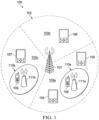
- FIG. 1 is a block diagram of a TDD wireless system 100, such as a TD-LTE system, that may employ dynamic reconfiguration of the UL/DL resource partitioning according to one embodiment.
- Base station 101 such as an evolved NodeB (eNB) in an LTE system, serves macro cell coverage area 102, which is further divided into cells 103a-c. It will be understood that a telecommunications network necessarily includes many more macro base stations, but only one is illustrated here to simplify the description.
- a TDD wireless system may also contain small cells such as micro- or pico-cells 110a/b, which are controlled by low power base stations 111a/b.
- UE 104-109 such as mobile telephone handsets, receive DL transmissions from base station 101 and 111a/b and send LTL transmissions to base station 101 and/or base stations 111a/b.
- the LTEs may include current devices 108-109 which comply with a current standard or protocol version (e.g., LTE Release 12), while other, legacy devices 104-107 may comply with an older version of the standard or protocol (e.g., LTE Release 8/9 or 10).
- Each base station 101, 111a/b may signal the cell-specific UL/DL configuration to be used by the LTEs deployed in a cell under its control using the broadcast information in System Information Block Type 1.
- dynamic TDD may be configured for user equipment served by base stations 111a/b.
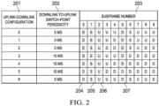
- FIG. 2 is a table illustrating different TDD UL/DL configurations that can be used in an LTE system according to one embodiment.
- Column 201 numbers seven (0-6) different UL/DL configurations.
- Column 202 identifies the DL-to-UL switch-point periodicity for each LTL/DL configuration.
- Column 203 identifies the subframe types for each configuration. For each subframe in a radio frame, "D” denotes subframes that are reserved for downlink transmissions, "U” denotes subframe that are reserved for uplink transmissions, and "S” denotes special subframes.
- the special subframes have three fields: downlink pilot time slot (DwPTS), guard period (GP), and uplink pilot time slot (UpPTS).
- DwPTS downlink pilot time slot
- GP guard period
- UpPTS uplink pilot time slot
- the DwPTS portion may be used for downlink data transmission, while the UpPTS portion may be used for sounding the uplink channel or for transmitting random access preambles.
- the GP portion of a special subframe allows switching between DL reception to UL transmission as well as coexistence with other TDD systems, such as time division-synchronous code division multiple access (TD-SCDMA).
- Shaded columns 204-207 indicate that the same subframe type is present in that subframe for each of the UL/DL configurations. These are referred to herein as fixed subframes since the communication direction does not change across all possible UL/DL configurations.
- the fixed subframes include subframes 0, 1, 2 and 5.
- Base stations 101 and 111a/b inform the UEs of the cell-specific TDD UL/DL configuration using information broadcast in system information block type 1 (SIB1).
- SIB1 system information block type 1
- the same UL/DL configuration may be assigned to each cell 103a-c and 110a/b operating on the same or on adjacent carrier frequencies.
- a UE is capable of adaptive TDD reconfiguration, then the UE also signals adaptive TDD capabilities to the serving base station 101, 111a/b.
- the adaptive TDD capability signaling from the UEs includes the case where adaptive TDD capability is mandatory for all TDD-capable UEs of a certain LTE release.
- base station 111a may choose to configure a specific LTE by dedicated radio resource control (RRC) signaling for dynamic reconfiguration of the TDD UL/DL configuration.
- RRC radio resource control
- the cell-specific UL/DL configuration can be dynamically reconfigured to a UE-specific UL/DL configuration that is different from the UL/DL configuration broadcasted in the SIB1.
- the base station may configure the same LTL/DL configuration for a group of UEs in one cell.
- DL subframes in which legacy UEs expect cell-specific reference signals (CRS) should not be reconfigured to LTL subframes.
- CRS cell-specific reference signals
- This restriction on the configurability of DL subframes applies to cells operating with LTE transmission formats that require CRS to be present in DL subframes and also in the DwPTS portion of the special subframes.
- An evolved transmission format may also be introduced for a future LTE release, where CRS is not present in a subset of DL subframes, including the case of all DL subframes.
- This evolved transmission format is also known as a New Carrier Type and is not backward compatible, so it is not supported by UEs of an earlier LTE release. Since some or all DL subframes in a cell operating with the evolved transmission format do not contain CRS it is possible to reconfigure these DL subframes to UL subframes.
- the set of subframes for which the transmission direction can be dynamically reconfigured are known as flexible subframes.
- Dynamic variation of the UL/DL configuration affects semi-statically configured UL transmission parameters for sounding reference signal (SRS), channel state information (CSI), HARQ-ACK feedback and preamble transmission on the physical random access channel (PRACH).
- SRS sounding reference signal
- CSI channel state information
- PRACH preamble transmission on the physical random access channel
- the TDD UL/DL reconfiguration command for a UE may be dynamically signaled in a downlink control information (DCI) format carried in a physical downlink control channel (PDCCH) or an enhanced physical downlink control channel (EPDCCH).
- DCI downlink control information
- the reconfiguration command can be contained in a medium access channel (MAC) control element that is scheduled by a PDCCH or EPDCCH.
- MAC medium access channel
- a three-bit field in the control information payload may be used to indicate which of the seven TDD UL/DL configurations should be used by the UE in a next time period.
- a LTE is configured by RRC signaling for dynamic reconfiguration of the TDD UL/DL configuration.
- FIG. 3 illustrates reception of the UL/DL reconfiguration signaling and the activation time definition according to one embodiment.
- Each dynamically signaled UL/DL configuration is assumed to be valid for at least one radio frame.
- Each radio frame includes ten subframes SF m .
- the UL/DL reconfiguration takes place at a radio frame boundary, such as after all of the subframes for a radio frame are complete.
- subframes 0 (SF 0 ) and 5 (SFs) are fixed DL subframes
- the UE monitors at least subframes 0 and/or 5 for a PDCCH/EPDCCH indicating (or scheduling the indication of) an LTL/DL reconfiguration.
- k may be 1 for the fastest reconfiguration interval (so reconfiguration occurs the very next radio frame), or k may be 4 for a 40ms reconfiguration interval. It will be understood that any other values of k may also be used to designate the interval before LTL/DL reconfiguration occurs.
- LTL/DL reconfiguration may follow a change notification window, wherein any reconfiguration signal that is detected within the current change notification window indicates that the signaled LTL/DL reconfiguration shall take effect at the next notification window boundary.
- a notification window boundary may be defined as the boundary of a radio frame for which the modulus operation on two integers, one being the system frame number (SFN) of that radio frame and one being the modification period, returns zero.
- SFN system frame number
- the reconfiguration signaling can be transmitted in a DCI format.
- a DCI format with a small payload can be used to transmit the LTL/DL reconfiguration command because it allows usage of a low rate error control code for reliable reception at the UE.
- the payload size of DCI format 1A can be re-used to reconfigure the TDD UL/DL configuration.
- Other small payload DCI formats are not precluded such as DCI format 1C.
- the LTE monitors DCI format 1A with the cyclic redundancy check (CRC) scrambled by the cell radio network temporary identifier (C-RNTI) for a dynamic UL/DL reconfiguration.
- CRC cyclic redundancy check
- C-RNTI cell radio network temporary identifier
- a one-bit field is designated in DCI format 1A to distinguish between physical downlink shared channel (PDSCH) scheduling and TDD UL/DL reconfiguration. For example, if the designated bit value is "0", then the detected DCI format 1A schedules PDSCH; however, if the bit value is "1", the detected DCI format 1A indicates a UL/DL reconfiguration.
- bit fields defined for signaling include: the new UL/DL configuration (three bits required); optional fields indicating changes to SRS transmission and CSI reporting configurations according to the new UL/DL configuration; and all the remaining bits in format 1A for compact scheduling assignment of one PDSCH codeword are set to zero.
- a new DCI format is defined for signaling TDD UL/DL reconfiguration.
- the new DCI format includes: the CRC of the reconfiguration DCI payload scrambled with the C-RNTI, or, alternatively, a different RNTI can be used to scramble the CRC of the reconfiguration DCI payload; a three-bit field indicating the new LTL/DL configuration; and optional bit fields indicating changes to the SRS transmission and CSI reporting configurations according to the new UL/DL configuration.
- the LTE monitors the UL/DL reconfiguration DCI format only in subframes 0 and/or 5 of radio frames within a change notification window.
- a LTE is semi-statically configured by RRC signaling for periodic and/or aperiodic sounding with dedicated parameters, such as an SRS periodicity T SRS and SRS subframe offset T offset . Since sounding is semi-statically configured, it may happen that the sounding subframe according to a cell-specific TDD UL/DL configuration signaled in SIB1 is now a DL subframe after dynamic reconfiguration. Accordingly, a new mechanism is useful to support SRS transmission for adaptive reconfiguration of the TDD UL/DL configuration.
- the following example methods enable sounding for adaptive TDD UL/DL configuration.
- the TDD reconfiguration command contains an SRS delta offset field ( ⁇ offset ). This field is used to adjust the SRS subframe offset such that the SRS is sounded on a valid UL subframe in the dynamically signaled TDD UL/DL configuration.
- the SRS delta offset applies for whatever sounding (such as periodic and/or aperiodic) is configured for the UE.
- the UL/DL configuration is dynamically reconfigured to TDD UL/DL configuration 1, wherein subframe 9 is now a DL subframe.
- a four-bit field is needed for the SRS offset field to account for ⁇ offset in the range ⁇ 0, 1, 2,...., 9 ⁇ (which allows ten subframe choices).
- the range can be reduced by removing these fixed DL subframes so that a three-bit ⁇ offset field would be sufficient (i.e., for eight subframe choices where ⁇ offset may represent the modified range ⁇ 1, 2, 3, 4, 6, 7, 8, 9 ⁇ ).
- the range of ⁇ offset depends on the dynamically signaled UL/DL configuration with respect to the SIB1-configured UL/DL configuration.
- the SRS delta offset field may apply to all LTEs configured for sounding.
- a LTE is configured to transmit SRS according to a periodic SRS configuration in a subframe m where subframe m is an UL subframe according to the SIB1-signaled UL/DL configuration, but following a dynamic reconfiguration of the TDD LTL/DL configuration, subframe m becomes a DL subframe. Accordingly, the LTE shall not transmit SRS because subframe m is no longer a UL subframe.
- the UE disregards the aperiodic SRS request and does not transmit SRS in subframe m, which is no longer an UL subframe.
- a LTE detects a PDCCH in radio frame n.
- the PDCCH contains a positive SRS request that schedules SRS transmission for subframe m of radio frame n + k, where k ⁇ 1. If the TDD UL/DL configuration is changed for radio frame n + k such that subframe m in radio frame n + k is no longer a valid cell-specific SRS subframe, then the UE transmits the aperiodic SRS in the first valid cell-specific SRS subframe following subframe m in radio frame n + k. Alternatively, the UE may transmit the aperiodic SRS in the first valid UE-specific aperiodic SRS subframe following subframe m in radio frame n + k.
- An LTL subframe may be reconfigured to a DL subframe in an LTE system and not affect legacy operation. This may be achieved, for example, by not scheduling physical uplink shared channel (PUSCH), physical uplink control channel (PUCCH), SRS or PRACH for these subframes.
- PUSCH physical uplink shared channel
- PUCCH physical uplink control channel
- SRS or PRACH for these subframes.
- the SRS configuration is semi-statically configured for the UE by RRC signaling
- dynamic reconfiguration of a cell-specific SRS subframe to a DL subframe may cause LTL-to-DL interference.
- a LTE that is not configured for dynamic TDD UL/DL reconfiguration may transmit SRS and cause interference to another UE receiving in the DL.
- the following interference avoidance mechanism may be used in this situation. If PDSCH and/or EPDCCH are transmitted in a subframe that is semi-statically configured by RRC signaling as a cell-specific SRS subframe, the PDSCH/EPDCCH
- the UE may be configured with at least two subframe sets: one for reporting CSI of fixed subframes, and the other for reporting CSI of flexible subframes.
- a CSI reference resource is a combination of a time domain and frequency domain resource where the CSI is measured.
- the CSI reference resource is valid only if the CSI reference resource occurs in a DL subframe according to the currently active dynamically signaled UL/DL configuration. It is also possible to support a CSI reference resource contained in a special subframe according to the currently active dynamically signaled UL/DL configuration if the Special Subframe configuration contains at least four orthogonal frequency division multiplex (OFDM) symbols in the DwPTS region.
- OFDM orthogonal frequency division multiplex
- the dynamically signaled TDD reconfiguration command contains CSI offset fields in the event that the subframe where the CSI is to be reported has been dynamically reconfigured as a DL subframe.
- the minimum information to be captured in the UL/DL reconfiguration command is a delta subframe offset that adjusts the CQI subframe offset N OFFSET,CQI .
- the LTE transmits CSI only in a subframe configured for LTL transmissions in the dynamically signaled UL/DL configuration. Accordingly, if an UL subframe according to the SIB1 UL/DL configuration is adaptively reconfigured to a DL subframe, and the UE is semi-statically configured to transmit a periodic CSI report in this same subframe, the UE does not transmit the periodic CSI report.
- the UE when the UE is configured for fast adaptation of the TDD UL/DL configuration, then the UE does not transmit periodic CSI reports according to the semi-statically configured periodic CSI reporting configuration.
- the LTE clears the periodic CSI reporting configuration including any configured PUCCH Format 2 resource.
- the UE disables the periodic CSI reporting configuration and re-activates the CSI reporting configuration if the network disables fast adaptation of the TDD UL/DL configuration.
- the aperiodic CSI reporting configuration remains valid for this UE. For example, if a UE detects a PDCCH in subframe k of radio frame n containing a positive CSI request for subframe m in radio frame n + 1, and if the TDD LTL/DL configuration is changed for radio frame n + 1 such that subframe m in radio frame n + 1 is no longer an UL subframe, then the UE transmits the CSI report in the first UL subframe following subframe m in radio frame n + 1.
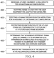
- FIG. 4 is a flowchart illustrating dynamic reconfiguration of the UL/DL configuration in a TDD wireless communication system.
- a cell-specific TDD UL/DL configuration is received at a UE.
- a UE notifies the base station that the UE has adaptive TDD capabilities.
- the user equipment detects a dynamic reconfiguration instruction for an assigned TDD UL/DL configuration.
- the UE restricts reconfiguration of the TDD UL/DL configuration at the UE to occur only at a specific future radio frame boundary.
- step 405 the LTE determines that a SRS or CSI transmission is configured to transmit in a subframe that has been reconfigured by the dynamic reconfiguration instruction as a DL subframe.
- step 406 the UE prevents the transmission of the SRS or CSI in the reconfigured DL subframe.
- the UE may be configured to monitor one or more designated subframes for the dynamic reconfiguration instruction, wherein the designated subframes corresponding to DL subframes in all available UL/DL configurations for the TDD wireless communication system, such as subframes 0 and 5 in an LTE system.
- a dynamic reconfiguration instruction received by the UE in subframe n may include an instruction to apply a new UL/DL configuration in a later subframe n+k, where k is an integer.
- the UE then applies the UL/DL reconfiguration in subframe n+k.
- the UE may apply the UL/DL reconfiguration after a change notification window.
- the UE may detect a dynamic reconfiguration instruction during a current change notification window.
- the LTE then applies the UL/DL reconfiguration at a next change notification window boundary.
- the LTE may receive a dynamic reconfiguration instruction in dynamic signaling from the base station.
- the UE may monitor a DCI format carried in a PDCCH/EPDCCH from the base station.
- the UE determines whether the DCI schedules a PDSCH or indicates a UL/DL reconfiguration based upon a setting of a one-bit field in the DCI.
- the DCI format comprises a new UL/DL configuration, changes to SRS transmission, and CSI reporting configurations according to the new UL/DL configuration.
- the dynamic reconfiguration instruction may contain an SRS and/or CSI delta offset field.
- the LTE adjusts an SRS subframe offset based upon the delta offset field so that the SRS or CSI is sent on a valid UL subframe in a new TDD UL/DL configuration signaled in the dynamic reconfiguration instruction.
- the SRS delta offset field value may be selected by ignoring any subframes that are fixed as DL subframes in all available UL/DL configurations.
- the UE may detect a PDCCH containing a request that schedules an SRS transmission in a designated subframe of a later radio frame.
- the UE determines that the designated subframe of the later radio frame is no longer a valid cell-specific SRS subframe due to a UL/DL reconfiguration.
- the UE may then transmit the SRS in a first valid cell-specific SRS subframe following the designated subframe in the later radio frame or in a first valid UE-specific aperiodic SRS subframe following the designated subframe in the later radio frame.
- FIG. 5 is a flowchart illustrating a procedure for determining a valid CSI reference resource.
- the UE receives a CSI reporting configuration by RRC signaling.
- the LTE detects a dynamic reconfiguration instruction for an assigned UL/DL configuration for a set of radio frames.
- the UE detects downlink control information in subframe N containing an aperiodic CSI request for later subframe N+K.
- the UE determines whether the CSI reference resource is a DL subframe or special subframe in the UL/DL configuration that was received in the dynamic reconfiguration instruction. If the CSI reference resource is a DL subframe or special subframe, then the UE performs a CSI measurement in the reference resource and subsequently transmits a CSI report in subframe N+K in step 505. Otherwise, if the CSI reference is an UL subframe in the UL/DL configuration received in the dynamic reconfiguration instruction, then the LTE does not perform a CSI measurement as indicated in step 506.
- FIG. 6 is a block diagram illustrating internal details of a mobile UE 601 and an eNB 602 operating in a network system such as illustrated in FIG. 1 .
- Mobile UE 601 may represent any of a variety of devices such as a server, a desktop computer, a laptop computer, a cellular phone, a personal digital assistant (PDA), a smart phone or other electronic devices.
- the electronic mobile LTE 601 communicates with eNB 602 based on a LTE or evolved universal terrestrial radio access (E-UTRA) protocol.
- E-UTRA evolved universal terrestrial radio access
- another communication protocol now known or later developed can be used.
- Mobile LTE 601 comprises a processor 603 coupled to a memory 604 and a transceiver 605.
- the memory 604 stores (software) applications 606 for execution by the processor 603.
- the applications could comprise any known or future application useful for individuals or organizations. These applications could be categorized as operating systems (OS), device drivers, databases, multimedia tools, presentation tools, Internet browsers, emailers, voice-over-Internet protocol (VOIP) tools, file browsers, firewalls, instant messaging, finance tools, games, word processors or other categories. Regardless of the exact nature of the applications, at least some of the applications may direct the mobile LTE 601 to transmit LTL signals to eNB (base station) 602 periodically or continuously via the transceiver 605.
- eNB base station
- Transceiver 605 includes uplink logic which may be implemented by execution of instructions that control the operation of the transceiver. Some of these instructions may be stored in memory 604 and executed when needed by processor 603. As would be understood by one of skill in the art, the components of the uplink logic may involve the physical (PHY) layer and/or the media access control (MAC) layer of the transceiver 605. Transceiver 605 includes one or more receivers 607 and one or more transmitters 608.
- PHY physical
- MAC media access control
- Processor 603 may send or receive data to various input/output devices 609.
- a subscriber identity module (SIM) card stores and retrieves information used for making calls via the cellular system.
- a Bluetooth baseband unit may be provided for wireless connection to a microphone and headset for sending and receiving voice data.
- Processor 603 may send information to a display unit for interaction with a user of mobile UE 601 during a call process.
- the display may also display pictures received from the network, from a local camera, or from other sources such as a universal serial bus (USB) connector.
- Processor 603 may also send a video stream to the display that is received from various sources such as the cellular network via RF transceiver 605 or the camera.
- transmitter 607 may be or become non-synchronized with its serving eNB. In this case, it sends a random access signal. As part of this procedure, it determines a preferred size for the next data transmission, referred to as a message, by using a power threshold value provided by the serving eNB, as described in more detail above.
- the message preferred size determination is embodied by executing instructions stored in memory 604 by processor 603. In other embodiments, the message size determination may be embodied by a separate processor/memory unit, by a hardwired state machine, or by other types of control logic, for example.
- eNB 602 comprises a processor 610 coupled to a memory 611, symbol processing circuitry 612, and a transceiver 613 via backplane bus 614.
- the memory stores applications 615 for execution by processor 610.
- the applications could comprise any known or future application useful for managing wireless communications. At least some of the applications 615 may direct eNB 602 to manage transmissions to or from mobile UE 601.
- Transceiver 613 comprises an uplink resource manager, which enables eNB 602 to selectively allocate uplink physical uplink shared channel (PUSCH) resources to mobile UE 601.
- the components of the uplink resource manager may involve the physical (PHY) layer and/or the media access control (MAC) layer of the transceiver 613.
- Transceiver 613 includes at least one receiver 615 for receiving transmissions from various LTEs within range of eNB 602 and at least one transmitter 616 for transmitting data and control information to the various UEs within range of eNB 602.
- the uplink resource manager executes instructions that control the operation of transceiver 613. Some of these instructions may be located in memory 611 and executed when needed on processor 610.
- the resource manager controls the transmission resources allocated to each UE 601 served by eNB 602 and broadcasts control information via the PDCCH.
- UE 601 may receive TTD UL/DL configuration instructions from eNB 602.
- Symbol processing circuitry 612 performs demodulation using known techniques. Random access signals are demodulated in symbol processing circuitry 612. During transmission and reception of voice data or other application data, receiver 615 may receive a random access signal from a UE 601. The random access signal is encoded to request a message size that is preferred by UE 601. UE 601 determines the preferred message size by using a message threshold provided by eNB 602.
Landscapes
- Engineering & Computer Science (AREA)
- Computer Networks & Wireless Communication (AREA)
- Signal Processing (AREA)
- Mobile Radio Communication Systems (AREA)
- Time-Division Multiplex Systems (AREA)
Abstract
Description
- This relates in general to wireless communication such as wireless telephony, and in particular to a time division duplex (TDD) wireless communication system.
- TDD wireless communication systems transmit and receive data on a single carrier frequency. Uplink (UL) and downlink (DL) transmissions are multiplexed by time slots within a fixed time interval. Different UL/DL ratios may be selected depending upon the degree of asymmetry in the DL and LTL traffic rates. For a traditional homogeneous deployment of macro cells, the traffic patterns are relatively semi-static; and the TDD LTL/DL configuration, which defines the UL/DL time allocation, may remain unchanged for time intervals of at least hundreds of milliseconds or seconds. However, in heterogeneous deployment scenarios, such as networks consisting of small cells with or without a macro cell overlay, the UL and DL traffic patterns are more dynamic in nature. Accordingly, system capacity may be significantly increased by adaptively reconfiguring the TDD UL/DL configuration in response to fast changes in UL and DL traffic patterns.
- Another feature of traditional TDD systems is that cells within a geographical area may be configured with the same LTL/DL configuration to avoid intercell LTL-to-DL and DL-to-UL interference. When intercell UL-to-DL interference occurs, a UL transmission in one cell interferes with DL reception in a neighboring cell. When intercell DL-to-UL interference occurs, the DL transmission in one cell interferes with the UL reception in a different cell. Such intercell interference may occur both when the neighboring cells are operating on the same carrier frequency and when they are operating on different but adjacent carrier frequencies. If the UL/DL configuration in one cell is adaptively reconfigured based on intra-cell traffic patterns, then this change may cause severe co-channel and even adjacent channel interference to neighboring cells.
- In described examples, signaling mechanisms enable dynamic reconfiguration of the UL/DL resource partitioning by a base station for user equipment (UE) in a TDD wireless communication system, such as the 3GPP TDD Long Term Evolution (TD-LTE) system. The dynamic reconfiguration of the UL/DL resource partitioning may also be applied to any other TDD wireless system employing dynamic reconfiguration of the TDD LTL/DL configuration.
The invention also covers the following: - 1. A method, comprising:
- receiving, at a user equipment (UE) in a time division duplex (TDD) wireless communication system, a cell-specific TDD uplink (LTL)/downlink (DL) configuration for a plurality of radio frames;
- notifying a base station in the TDD wireless communication system that the UE has adaptive TDD capabilities;
- detecting, at the user equipment, a dynamic reconfiguration signal for an assigned TDD UL/DL configuration; and
- restricting activation of the signaled TDD LTL/DL configuration at the LTE to occur only at future radio frame boundaries.
- 2. The method of
item 1, further comprising monitoring one or more designated subframes for the dynamic reconfiguration signal, the designated subframes corresponding to DL subframes that are common to all available UL/DL configurations for the TDD wireless communication system. - 3. The method of
item 1, wherein a dynamic reconfiguration signal received in subframe n comprises an instruction to apply a new TDD UL/DL configuration in subframe n+k, where k is an integer. - 4. The method of
item 1, further comprising applying a UL/DL reconfiguration after a change notification window. - 5. The method of
item 4, further comprising:- detecting the dynamic reconfiguration signal during a current change notification window; and
- applying a UL/DL reconfiguration at a next change notification window boundary.
- 6. The method of
item 1, further comprising:- monitoring a downlink control information (DCI) format carried in a physical downlink control channel (PDCCH)/enhanced physical downlink control channel (EPDCCH) from the base station; and
- determining, based upon a setting of a one-bit field in the DCI, whether the DCI schedules a physical downlink shared channel (PDSCH) or indicates a UL/DL reconfiguration.
- 7. The method of
item 6, wherein, when a UL/DL reconfiguration is indicated, the DCI format comprises a new UL/DL configuration, changes to sounding reference signal (SRS) transmission, and channel state information (CSI) reporting configurations according to the new UL/DL configuration. - 8. The method of
item 1, wherein the dynamic reconfiguration signal contains a sounding reference signal (SRS) delta offset field, the method further comprising adjusting an SRS subframe offset based upon the delta offset field so that the SRS is sounded on a valid LTL subframe in a new TDD LTL/DL configuration signaled in the dynamic reconfiguration instruction. - 9. The method of
item 8, wherein the SRS delta offset field value is selected by ignoring any subframes that are fixed as DL subframes in all available UL/DL configurations. - 10. The method of
item 1, further comprising:- determining that a sounding reference signal (SRS) transmission is configured to transmit in a subframe that has been reconfigured by the dynamic reconfiguration instruction as a DL subframe; and
- preventing the transmission of the SRS in the reconfigured DL subframe.
- 11. The method of
item 1, further comprising:- detecting a physical downlink control channel (PDCCH) containing a request that schedules a sounding reference signal (SRS) transmission in a designated subframe of a later radio frame;
- determining that the designated subframe of the later radio frame is no longer a valid cell-specific SRS subframe due to a UL/DL reconfiguration; and
- transmitting the SRS in a first valid cell-specific SRS subframe following the designated subframe in the later radio frame.
- 12. The method of
item 1, further comprising:- detecting a physical downlink control channel (PDCCH) containing a request that schedules a sounding reference signal (SRS) transmission in a designated subframe of a later radio frame;
- determining that the designated subframe of the later radio frame is no longer a valid cell-specific SRS subframe due to a UL/DL reconfiguration; and
- transmitting the SRS in a first valid UE-specific aperiodic SRS subframe following the designated subframe in the later radio frame.
- 13. The method of
item 1, wherein the dynamic reconfiguration instruction contains a channel state information (CSI) delta offset field. - 14. The method of
item 1, further comprising determining that a Channel State Information reference resource is valid only if the resource occurs in a subframe indicated as downlink by the currently active dynamically signaled UL/DL configuration. - 15. The method of
item 1, further comprising:- determining that a Channel State Information reference resource is valid only if the resource occurs in a subframe indicated as a special subframe by the currently active dynamically signaled UL/DL configuration; and
- if the Special Subframe configuration contains at least 4 OFDM symbols in the downlink portion of the special subframe.
- 16. The method of
item 1, further comprising:- determining that a channel state information (CSI) transmission is configured to transmit in a subframe that has been reconfigured by the dynamic reconfiguration instruction as a DL subframe; and
- preventing the transmission of the CSI in the reconfigured DL subframe.
- 17. A user equipment device, comprising:
a processor circuit configured to:- receive a cell-specific time division duplex (TDD) uplink (LTL)/downlink (DL) configuration for a plurality of subframes within a radio frame;
- detect a dynamic reconfiguration signal for an assigned TDD LTL/DL configuration; and
- restrict reconfiguration of a TDD LTL/DL configuration to occur only at future radio frame boundaries.
- 18. The device of item 17, wherein the processor is configured to apply a new TDD UL/DL configuration in a subframe n+k, where k is an integer, following instructions received in a dynamic reconfiguration signal received in subframe n.
- 19. The device of item 17, wherein the processor is configured to apply a UL/DL reconfiguration after a change notification window.
- 20. The device of item 17, wherein the processor is configured to:
- prepare to adapt its LTL/DL configuration based on a dynamic reconfiguration signal received in downlink control information from a base station;
- monitor a downlink control information (DCI) format carried in a physical downlink control channel (PDCCH)/enhanced physical downlink control channel (EPDCCH) from the base station; and
- determine, based upon a setting of a one-bit field in the DCI, whether the DCI schedules a physical downlink shared channel (PDSCH) or indicates a UL/DL reconfiguration,
- wherein, when a UL/DL reconfiguration is indicated, the DCI format comprises a new UL/DL configuration, changes to sounding reference signal (SRS) transmission, and channel state information (CSI) reporting configurations according to the new UL/DL configuration.
- 21. The device of item 17, wherein the dynamic reconfiguration instruction contains a sounding reference signal (SRS) delta offset field or a channel state information (CSI) delta offset field, the method further comprising adjusting an SRS subframe offset based upon the delta offset field so that the SRS or CSI is sounded on a valid UL subframe in a new TDD UL/DL configuration signaled in the dynamic reconfiguration instruction.
- 22. The device of item 17, wherein the processor is configured to:
- determine that a sounding reference signal (SRS) or channel state information (CSI) transmission is configured to transmit in a subframe that has been reconfigured by the dynamic reconfiguration instruction as a DL subframe; and
- prevent the transmission of the SRS or CSI in the reconfigured DL subframe.
-
-
FIG. 1 is a block diagram of a TDD wireless system, such as a TD-LTE system, that may employ dynamic reconfiguration of the UL/DL resource partitioning according to one embodiment. -
FIG. 2 is a table illustrating different TDD UL/DL configurations that can be used in an LTE system according to one embodiment. -
FIG. 3 illustrates reception of the LTL/DL reconfiguration signal and the activation time according to one embodiment. -
FIG. 4 is a flowchart illustrating dynamic reconfiguration of the UL/DL resource partitioning in a TDD wireless communication system. -
FIG. 5 is a flowchart illustrating a procedure for determining a valid CSI reference resource. -
FIG. 6 is a block diagram illustrating internal details of a mobile UE and an eNB operating in a network system such as illustrated inFIG. 1 . -
FIG. 1 is a block diagram of aTDD wireless system 100, such as a TD-LTE system, that may employ dynamic reconfiguration of the UL/DL resource partitioning according to one embodiment.Base station 101, such as an evolved NodeB (eNB) in an LTE system, serves macrocell coverage area 102, which is further divided intocells 103a-c. It will be understood that a telecommunications network necessarily includes many more macro base stations, but only one is illustrated here to simplify the description. A TDD wireless system may also contain small cells such as micro- or pico-cells 110a/b, which are controlled by lowpower base stations 111a/b. User equipment (UE) 104-109, such as mobile telephone handsets, receive DL transmissions frombase station base station 101 and/orbase stations 111a/b. The LTEs may include current devices 108-109 which comply with a current standard or protocol version (e.g., LTE Release 12), while other, legacy devices 104-107 may comply with an older version of the standard or protocol (e.g.,LTE Release 8/9 or 10). Eachbase station Information Block Type 1. In the embodiment illustrated inFIG. 1 , dynamic TDD may be configured for user equipment served bybase stations 111a/b. -
FIG. 2 is a table illustrating different TDD UL/DL configurations that can be used in an LTE system according to one embodiment.Column 201 numbers seven (0-6) different UL/DL configurations.Column 202 identifies the DL-to-UL switch-point periodicity for each LTL/DL configuration.Column 203 identifies the subframe types for each configuration. For each subframe in a radio frame, "D" denotes subframes that are reserved for downlink transmissions, "U" denotes subframe that are reserved for uplink transmissions, and "S" denotes special subframes. The special subframes have three fields: downlink pilot time slot (DwPTS), guard period (GP), and uplink pilot time slot (UpPTS). The DwPTS portion may be used for downlink data transmission, while the UpPTS portion may be used for sounding the uplink channel or for transmitting random access preambles. The GP portion of a special subframe allows switching between DL reception to UL transmission as well as coexistence with other TDD systems, such as time division-synchronous code division multiple access (TD-SCDMA). Shaded columns 204-207 indicate that the same subframe type is present in that subframe for each of the UL/DL configurations. These are referred to herein as fixed subframes since the communication direction does not change across all possible UL/DL configurations. The fixed subframes includesubframes -
Base stations cell 103a-c and 110a/b operating on the same or on adjacent carrier frequencies. - If a UE is capable of adaptive TDD reconfiguration, then the UE also signals adaptive TDD capabilities to the serving
base station FIG. 1 base station 111a may choose to configure a specific LTE by dedicated radio resource control (RRC) signaling for dynamic reconfiguration of the TDD UL/DL configuration. Hence, for each adaptive TDD capable LTE the cell-specific UL/DL configuration can be dynamically reconfigured to a UE-specific UL/DL configuration that is different from the UL/DL configuration broadcasted in the SIB1. Moreover, the base station may configure the same LTL/DL configuration for a group of UEs in one cell. - Those UEs that are not configured for or are not capable of adaptive TDD operation use the UL/DL configuration signaled in SIB1. Accordingly, to maintain backward compatibility, DL subframes in which legacy UEs expect cell-specific reference signals (CRS) should not be reconfigured to LTL subframes. This restriction on the configurability of DL subframes applies to cells operating with LTE transmission formats that require CRS to be present in DL subframes and also in the DwPTS portion of the special subframes. An evolved transmission format may also be introduced for a future LTE release, where CRS is not present in a subset of DL subframes, including the case of all DL subframes. This evolved transmission format is also known as a New Carrier Type and is not backward compatible, so it is not supported by UEs of an earlier LTE release. Since some or all DL subframes in a cell operating with the evolved transmission format do not contain CRS it is possible to reconfigure these DL subframes to UL subframes. The set of subframes for which the transmission direction can be dynamically reconfigured are known as flexible subframes.
- Dynamic variation of the UL/DL configuration affects semi-statically configured UL transmission parameters for sounding reference signal (SRS), channel state information (CSI), HARQ-ACK feedback and preamble transmission on the physical random access channel (PRACH). The following issues are addressed in a system employing dynamic LTL/DL reconfiguration: (a) the actual time when the dynamic UL/DL reconfiguration becomes active must be unambiguous to both the base station and LTE; (b) for SRS transmissions, a change from an UL subframe to a DL subframe affects the definition of cell-specific and UE-specific SRS subframes; (c) for CSI reporting in semi-statically configured subframes, the base station scheduler may determine its actual reporting configuration based upon the UL/DL configuration signaled in
SIB 1; and (d) PRACH resources should be carefully configured to avoid UL-to-DL interference when a SIB 1-configured UL resource containing PRACH resources is dynamically reconfigured for DL. - In one embodiment, the TDD UL/DL reconfiguration command for a UE may be dynamically signaled in a downlink control information (DCI) format carried in a physical downlink control channel (PDCCH) or an enhanced physical downlink control channel (EPDCCH). Alternatively, the reconfiguration command can be contained in a medium access channel (MAC) control element that is scheduled by a PDCCH or EPDCCH. In either case, a three-bit field in the control information payload may be used to indicate which of the seven TDD UL/DL configurations should be used by the UE in a next time period.
- For signaling UL/DL reconfiguration, a LTE is configured by RRC signaling for dynamic reconfiguration of the TDD UL/DL configuration.
FIG. 3 illustrates reception of the UL/DL reconfiguration signaling and the activation time definition according to one embodiment. Each dynamically signaled UL/DL configuration is assumed to be valid for at least one radio frame. Each radio frame includes ten subframes SFm. The UL/DL reconfiguration takes place at a radio frame boundary, such as after all of the subframes for a radio frame are complete. Since subframes 0 (SF0) and 5 (SFs) are fixed DL subframes, the UE monitors atleast subframes 0 and/or 5 for a PDCCH/EPDCCH indicating (or scheduling the indication of) an LTL/DL reconfiguration. - For example, if dynamic reconfiguration signaling 301 is detected in radio frame n (RFn) 302, the new LTL/DL configuration becomes active at
radio frame boundary 303 of subsequent radio frame n+k (RFn+k) 304. For example, k may be 1 for the fastest reconfiguration interval (so reconfiguration occurs the very next radio frame), or k may be 4 for a 40ms reconfiguration interval. It will be understood that any other values of k may also be used to designate the interval before LTL/DL reconfiguration occurs. - More generally, LTL/DL reconfiguration may follow a change notification window, wherein any reconfiguration signal that is detected within the current change notification window indicates that the signaled LTL/DL reconfiguration shall take effect at the next notification window boundary. A notification window boundary may be defined as the boundary of a radio frame for which the modulus operation on two integers, one being the system frame number (SFN) of that radio frame and one being the modification period, returns zero.
- In another embodiment, if dedicated PHY signaling is used in an LTE system, then the reconfiguration signaling can be transmitted in a DCI format. A DCI format with a small payload can be used to transmit the LTL/DL reconfiguration command because it allows usage of a low rate error control code for reliable reception at the UE. In one embodiment the payload size of DCI format 1A can be re-used to reconfigure the TDD UL/DL configuration. Other small payload DCI formats are not precluded such as DCI format 1C.
- In a first adaptive LTL/DL reconfiguration technique, the LTE monitors DCI format 1A with the cyclic redundancy check (CRC) scrambled by the cell radio network temporary identifier (C-RNTI) for a dynamic UL/DL reconfiguration. A one-bit field is designated in DCI format 1A to distinguish between physical downlink shared channel (PDSCH) scheduling and TDD UL/DL reconfiguration. For example, if the designated bit value is "0", then the detected DCI format 1A schedules PDSCH; however, if the bit value is "1", the detected DCI format 1A indicates a UL/DL reconfiguration.
- If the designated bit value is "1", bit fields defined for signaling include: the new UL/DL configuration (three bits required); optional fields indicating changes to SRS transmission and CSI reporting configurations according to the new UL/DL configuration; and all the remaining bits in format 1A for compact scheduling assignment of one PDSCH codeword are set to zero.
- In a second adaptive UL/DL reconfiguration technique, a new DCI format is defined for signaling TDD UL/DL reconfiguration. The new DCI format includes: the CRC of the reconfiguration DCI payload scrambled with the C-RNTI, or, alternatively, a different RNTI can be used to scramble the CRC of the reconfiguration DCI payload; a three-bit field indicating the new LTL/DL configuration; and optional bit fields indicating changes to the SRS transmission and CSI reporting configurations according to the new UL/DL configuration. The LTE monitors the UL/DL reconfiguration DCI format only in
subframes 0 and/or 5 of radio frames within a change notification window. - For SRS transmission, a LTE is semi-statically configured by RRC signaling for periodic and/or aperiodic sounding with dedicated parameters, such as an SRS periodicity TSRS and SRS subframe offset Toffset. Since sounding is semi-statically configured, it may happen that the sounding subframe according to a cell-specific TDD UL/DL configuration signaled in SIB1 is now a DL subframe after dynamic reconfiguration. Accordingly, a new mechanism is useful to support SRS transmission for adaptive reconfiguration of the TDD UL/DL configuration. The following example methods enable sounding for adaptive TDD UL/DL configuration.
- In a first technique, the TDD reconfiguration command contains an SRS delta offset field (Δoffset). This field is used to adjust the SRS subframe offset such that the SRS is sounded on a valid UL subframe in the dynamically signaled TDD UL/DL configuration. After adaptive reconfiguration, the SRS subframe offset is given by Toffset_dynamic = (Toffset + Δoffset) mod X, where Toffset is the semi-statically configured SRS subframe offset, X is a parameter that determines the number of bits in the SRS delta offset field, and Toffset_dynamic is the dynamically reconfigured SRS subframe offset. The SRS delta offset applies for whatever sounding (such as periodic and/or aperiodic) is configured for the UE.
- In an example case, TDD UL/
DL configuration 0 is signaled in SIB1. Then, a UE that is capable of adaptive TDD reconfiguration is semi-statically configured for aperiodic sounding with TSRS = 10 and Toffset = 9. In a radio frame n, the UL/DL configuration is dynamically reconfigured to TDD UL/DL configuration 1, wherein subframe 9 is now a DL subframe. The SRS offset field is set to Δoffset = 9 and X = 10. Accordingly, Toffset_dynamic = 8, which is a valid LTL subframe for UL/DL configuration 1. - In the previous example, a four-bit field is needed for the SRS offset field to account for Δoffset in the range {0, 1, 2,...., 9} (which allows ten subframe choices). Alternatively, by noting that
subframes - If the reconfiguration command is signaled in a common DCI format or common MAC control element for a group of LTEs, the SRS delta offset field may apply to all LTEs configured for sounding.
- In a second technique, a LTE is configured to transmit SRS according to a periodic SRS configuration in a subframe m where subframe m is an UL subframe according to the SIB1-signaled UL/DL configuration, but following a dynamic reconfiguration of the TDD LTL/DL configuration, subframe m becomes a DL subframe. Accordingly, the LTE shall not transmit SRS because subframe m is no longer a UL subframe. Alternatively, if the UE is configured for aperiodic SRS transmission and scheduled to transmit aperiodic SRS in subframe m of a radio frame but subframe m becomes a DL subframe following a dynamic reconfiguration of the TDD LTL/DL configuration then the UE disregards the aperiodic SRS request and does not transmit SRS in subframe m, which is no longer an UL subframe.
- In a third technique, a LTE detects a PDCCH in radio frame n. The PDCCH contains a positive SRS request that schedules SRS transmission for subframe m of radio frame n + k, where k ≥ 1. If the TDD UL/DL configuration is changed for radio frame n + k such that subframe m in radio frame n + k is no longer a valid cell-specific SRS subframe, then the UE transmits the aperiodic SRS in the first valid cell-specific SRS subframe following subframe m in radio frame n + k. Alternatively, the UE may transmit the aperiodic SRS in the first valid UE-specific aperiodic SRS subframe following subframe m in radio frame n + k.
- An LTL subframe may be reconfigured to a DL subframe in an LTE system and not affect legacy operation. This may be achieved, for example, by not scheduling physical uplink shared channel (PUSCH), physical uplink control channel (PUCCH), SRS or PRACH for these subframes. However, since the SRS configuration is semi-statically configured for the UE by RRC signaling, dynamic reconfiguration of a cell-specific SRS subframe to a DL subframe may cause LTL-to-DL interference. As a result, a LTE that is not configured for dynamic TDD UL/DL reconfiguration may transmit SRS and cause interference to another UE receiving in the DL. The following interference avoidance mechanism may be used in this situation. If PDSCH and/or EPDCCH are transmitted in a subframe that is semi-statically configured by RRC signaling as a cell-specific SRS subframe, the PDSCH/EPDCCH are rate-matched around the SRS symbols in the subframe.
- Problems similar to the SRS transmission issues may also arise for periodic CSI reporting. These problems can occur because the UE is semi-statically configured by RRC signaling with a periodic CSI reporting configuration. The UE may be configured with at least two subframe sets: one for reporting CSI of fixed subframes, and the other for reporting CSI of flexible subframes.
- A CSI reference resource is a combination of a time domain and frequency domain resource where the CSI is measured. For a set of subframes that may be dynamically reconfigured to DL, the CSI reference resource is valid only if the CSI reference resource occurs in a DL subframe according to the currently active dynamically signaled UL/DL configuration. It is also possible to support a CSI reference resource contained in a special subframe according to the currently active dynamically signaled UL/DL configuration if the Special Subframe configuration contains at least four orthogonal frequency division multiplex (OFDM) symbols in the DwPTS region.
- In a first technique regarding the subframes where the CSI is transmitted from the UE to the base station, the dynamically signaled TDD reconfiguration command contains CSI offset fields in the event that the subframe where the CSI is to be reported has been dynamically reconfigured as a DL subframe. The minimum information to be captured in the UL/DL reconfiguration command is a delta subframe offset that adjusts the CQI subframe offset NOFFSET,CQI.
- In a second technique, the LTE transmits CSI only in a subframe configured for LTL transmissions in the dynamically signaled UL/DL configuration. Accordingly, if an UL subframe according to the SIB1 UL/DL configuration is adaptively reconfigured to a DL subframe, and the UE is semi-statically configured to transmit a periodic CSI report in this same subframe, the UE does not transmit the periodic CSI report.
- In a third technique, when the UE is configured for fast adaptation of the TDD UL/DL configuration, then the UE does not transmit periodic CSI reports according to the semi-statically configured periodic CSI reporting configuration. The LTE clears the periodic CSI reporting configuration including any configured
PUCCH Format 2 resource. In an alternative embodiment, the UE disables the periodic CSI reporting configuration and re-activates the CSI reporting configuration if the network disables fast adaptation of the TDD UL/DL configuration. - The aperiodic CSI reporting configuration remains valid for this UE. For example, if a UE detects a PDCCH in subframe k of radio frame n containing a positive CSI request for subframe m in radio frame n + 1, and if the TDD LTL/DL configuration is changed for radio frame n + 1 such that subframe m in radio frame n + 1 is no longer an UL subframe, then the UE transmits the CSI report in the first UL subframe following subframe m in radio
frame n + 1. -
FIG. 4 is a flowchart illustrating dynamic reconfiguration of the UL/DL configuration in a TDD wireless communication system. Instep 401, a cell-specific TDD UL/DL configuration is received at a UE. Instep 402, a UE notifies the base station that the UE has adaptive TDD capabilities. Instep 403, the user equipment detects a dynamic reconfiguration instruction for an assigned TDD UL/DL configuration. Instep 404, the UE restricts reconfiguration of the TDD UL/DL configuration at the UE to occur only at a specific future radio frame boundary. - In
step 405, the LTE determines that a SRS or CSI transmission is configured to transmit in a subframe that has been reconfigured by the dynamic reconfiguration instruction as a DL subframe. Instep 406, the UE prevents the transmission of the SRS or CSI in the reconfigured DL subframe. - The UE may be configured to monitor one or more designated subframes for the dynamic reconfiguration instruction, wherein the designated subframes corresponding to DL subframes in all available UL/DL configurations for the TDD wireless communication system, such as
subframes - A dynamic reconfiguration instruction received by the UE in subframe n may include an instruction to apply a new UL/DL configuration in a later subframe n+k, where k is an integer. The UE then applies the UL/DL reconfiguration in subframe n+k. Alternatively, the UE may apply the UL/DL reconfiguration after a change notification window. For example, the UE may detect a dynamic reconfiguration instruction during a current change notification window. The LTE then applies the UL/DL reconfiguration at a next change notification window boundary.
- The LTE may receive a dynamic reconfiguration instruction in dynamic signaling from the base station. For example, the UE may monitor a DCI format carried in a PDCCH/EPDCCH from the base station. The UE determines whether the DCI schedules a PDSCH or indicates a UL/DL reconfiguration based upon a setting of a one-bit field in the DCI. When a UL/DL reconfiguration is indicated, the DCI format comprises a new UL/DL configuration, changes to SRS transmission, and CSI reporting configurations according to the new UL/DL configuration.
- The dynamic reconfiguration instruction may contain an SRS and/or CSI delta offset field. The LTE adjusts an SRS subframe offset based upon the delta offset field so that the SRS or CSI is sent on a valid UL subframe in a new TDD UL/DL configuration signaled in the dynamic reconfiguration instruction. The SRS delta offset field value may be selected by ignoring any subframes that are fixed as DL subframes in all available UL/DL configurations.
- The UE may detect a PDCCH containing a request that schedules an SRS transmission in a designated subframe of a later radio frame. The UE determines that the designated subframe of the later radio frame is no longer a valid cell-specific SRS subframe due to a UL/DL reconfiguration. The UE may then transmit the SRS in a first valid cell-specific SRS subframe following the designated subframe in the later radio frame or in a first valid UE-specific aperiodic SRS subframe following the designated subframe in the later radio frame.
-
FIG. 5 is a flowchart illustrating a procedure for determining a valid CSI reference resource. Instep 501, the UE receives a CSI reporting configuration by RRC signaling. Instep 502, the LTE detects a dynamic reconfiguration instruction for an assigned UL/DL configuration for a set of radio frames. Instep 503, the UE detects downlink control information in subframe N containing an aperiodic CSI request for later subframe N+K. - In
step 504, the UE determines whether the CSI reference resource is a DL subframe or special subframe in the UL/DL configuration that was received in the dynamic reconfiguration instruction. If the CSI reference resource is a DL subframe or special subframe, then the UE performs a CSI measurement in the reference resource and subsequently transmits a CSI report in subframe N+K instep 505. Otherwise, if the CSI reference is an UL subframe in the UL/DL configuration received in the dynamic reconfiguration instruction, then the LTE does not perform a CSI measurement as indicated instep 506. -
FIG. 6 is a block diagram illustrating internal details of amobile UE 601 and aneNB 602 operating in a network system such as illustrated inFIG. 1 .Mobile UE 601 may represent any of a variety of devices such as a server, a desktop computer, a laptop computer, a cellular phone, a personal digital assistant (PDA), a smart phone or other electronic devices. In some embodiments, the electronicmobile LTE 601 communicates witheNB 602 based on a LTE or evolved universal terrestrial radio access (E-UTRA) protocol. Alternatively, another communication protocol now known or later developed can be used. -
Mobile LTE 601 comprises aprocessor 603 coupled to amemory 604 and atransceiver 605. Thememory 604 stores (software)applications 606 for execution by theprocessor 603. The applications could comprise any known or future application useful for individuals or organizations. These applications could be categorized as operating systems (OS), device drivers, databases, multimedia tools, presentation tools, Internet browsers, emailers, voice-over-Internet protocol (VOIP) tools, file browsers, firewalls, instant messaging, finance tools, games, word processors or other categories. Regardless of the exact nature of the applications, at least some of the applications may direct themobile LTE 601 to transmit LTL signals to eNB (base station) 602 periodically or continuously via thetransceiver 605. -
Transceiver 605 includes uplink logic which may be implemented by execution of instructions that control the operation of the transceiver. Some of these instructions may be stored inmemory 604 and executed when needed byprocessor 603. As would be understood by one of skill in the art, the components of the uplink logic may involve the physical (PHY) layer and/or the media access control (MAC) layer of thetransceiver 605.Transceiver 605 includes one ormore receivers 607 and one ormore transmitters 608. -
Processor 603 may send or receive data to various input/output devices 609. A subscriber identity module (SIM) card stores and retrieves information used for making calls via the cellular system. A Bluetooth baseband unit may be provided for wireless connection to a microphone and headset for sending and receiving voice data.Processor 603 may send information to a display unit for interaction with a user ofmobile UE 601 during a call process. The display may also display pictures received from the network, from a local camera, or from other sources such as a universal serial bus (USB) connector.Processor 603 may also send a video stream to the display that is received from various sources such as the cellular network viaRF transceiver 605 or the camera. - During transmission and reception of voice data or other application data,
transmitter 607 may be or become non-synchronized with its serving eNB. In this case, it sends a random access signal. As part of this procedure, it determines a preferred size for the next data transmission, referred to as a message, by using a power threshold value provided by the serving eNB, as described in more detail above. In this embodiment, the message preferred size determination is embodied by executing instructions stored inmemory 604 byprocessor 603. In other embodiments, the message size determination may be embodied by a separate processor/memory unit, by a hardwired state machine, or by other types of control logic, for example. -
eNB 602 comprises aprocessor 610 coupled to amemory 611,symbol processing circuitry 612, and atransceiver 613 viabackplane bus 614. Thememory stores applications 615 for execution byprocessor 610. The applications could comprise any known or future application useful for managing wireless communications. At least some of theapplications 615 may directeNB 602 to manage transmissions to or frommobile UE 601. -
Transceiver 613 comprises an uplink resource manager, which enableseNB 602 to selectively allocate uplink physical uplink shared channel (PUSCH) resources tomobile UE 601. As would be understood by one of skill in the art, the components of the uplink resource manager may involve the physical (PHY) layer and/or the media access control (MAC) layer of thetransceiver 613.Transceiver 613 includes at least onereceiver 615 for receiving transmissions from various LTEs within range ofeNB 602 and at least onetransmitter 616 for transmitting data and control information to the various UEs within range ofeNB 602. - The uplink resource manager executes instructions that control the operation of
transceiver 613. Some of these instructions may be located inmemory 611 and executed when needed onprocessor 610. The resource manager controls the transmission resources allocated to eachUE 601 served byeNB 602 and broadcasts control information via the PDCCH.UE 601 may receive TTD UL/DL configuration instructions fromeNB 602. -
Symbol processing circuitry 612 performs demodulation using known techniques. Random access signals are demodulated insymbol processing circuitry 612. During transmission and reception of voice data or other application data,receiver 615 may receive a random access signal from aUE 601. The random access signal is encoded to request a message size that is preferred byUE 601.UE 601 determines the preferred message size by using a message threshold provided byeNB 602. - Modifications are possible in the described embodiments, and other embodiments are possible, within the scope of the claims.
Claims (15)
- A method, comprising:receiving, at a user equipment (UE), a first time division duplex (TDD) uplink (UL)/downlink (DL) configuration via a system information block type 1 (SIB1);receiving, at the LTE, a periodic sounding reference signal (SRS) configuration that includes an SRS periodicity parameter and an SRS offset parameter;receiving, at the LTE, a reconfiguration signal via a downlink control information (DCI) format, the reconfiguration signal signaling a second TDD UL/DL configuration;activating the second TDD UL/DL configuration following a change notification window, wherein any reconfiguration signal that is detected in the change notification window indicates that the second TDD UL/DL configuration shall take effect at a next change notification window boundary; andnot transmitting, by the UE, an SRS in a subframe when the LTE is configured to transmit an SRS in the subframe according to the periodic SRS configuration and the second TDD UL/DL configuration indicates that the subframe is a downlink subframe.
- The method of claim 1, further comprising:
monitoring one or more designated subframes for the reconfiguration signal, the designated subframes corresponding to DL subframes that are common to all available UL/DL configurations for a TDD wireless communication system. - The method of claim 1, wherein a reconfiguration signal received in subframe n comprises an instruction to apply a new TDD UL/DL configuration in subframe n+k, where k is an integer.
- The method of claim 1, further comprising:monitoring a Downlink Control Information (DCI) format carried in a Physical Downlink Control Channel (PDCCH); anddetermining, based upon a setting of a one-bit field in the DCI, whether the DCI schedules a Physical Downlink Shared Channel (PDSCH) or indicates a UL/DL reconfiguration.
- The method of claim 4, wherein, when a UL/DL reconfiguration is indicated, the DCI format comprises a new UL/DL configuration, changes to Sounding Reference Signal (SRS) transmission, and Channel State Information (CSI) reporting configurations according to the new UL/DL configuration.
- The method of claim 1, further comprising:determining that a Sounding Reference Signal (SRS) transmission is configured to transmit in a subframe that has been reconfigured by the reconfiguration signal as a DL subframe; andpreventing the transmission of the SRS in the reconfigured DL subframe.
- The method of claim 1, further comprising:detecting a Physical Downlink Control Channel (PDCCH) containing a request that schedules a Sounding Reference Signal (SRS) transmission in a designated subframe of a later radio frame;determining that the designated subframe of the later radio frame is no longer a valid cell-specific SRS subframe due to a UL/DL reconfiguration; andtransmitting the SRS in a first valid cell-specific SRS subframe following the designated subframe in the later radio frame.
- The method of claim 1, further comprising:detecting a Physical Downlink Control Channel (PDCCH) containing a request that schedules a Sounding Reference Signal (SRS) transmission in a designated subframe of a later radio frame;determining that the designated subframe of the later radio frame is no longer a valid cell-specific SRS subframe due to a UL/DL reconfiguration; andtransmitting the SRS in a first valid UE-specific aperiodic SRS subframe following the designated subframe in the later radio frame.
- The method of claim 1, further comprising:
determining that a Channel State Information reference resource is valid only if the resource occurs in a subframe indicated as downlink by the currently active dynamically signaled UL/DL configuration. - The method of claim 1, further comprising:determining that a Channel State Information reference resource is valid only if the resource occurs in a subframe indicated as a special subframe by the currently active dynamically signaled UL/DL configuration; andif the Special Subframe configuration contains at least 4 OFDM symbols in the downlink portion of the special subframe.
- The method of claim 1, further comprising:determining that a Channel State Information (CSI) transmission is configured to transmit in a subframe that has been reconfigured by the reconfiguration signal as a DL subframe; andpreventing the transmission of the CSI in the reconfigured DL subframe.
- The method of claim 1,
wherein a change notification window boundary is defined as a system frame number (SFN) for which the modulus operation on first and second integers, the first integer being a frame number and the second integer being a modification period. - A user equipment (UE) device configured to perform the methods of any of claims 1-12.
- The UE device of claim 13 comprising:a transceiver; anda processor coupled to the transceiver.
- The LTE device of claim 14,wherein the transceiver is configured to receive the periodic SRS configuration that includes the SRS periodicity parameter and the SRS offset parameter, receive the first TDD uplink UL/DL configuration via the SIB 1, and receive the reconfiguration signal via the DCI format, the reconfiguration signal signaling the second TDD UL/DL configuration,wherein the processor circuit is configured to activate the second TDD UL/DL configuration following the change notification window, wherein any reconfiguration signal that is detected in the change notification window indicates that the second TDD UL/DL configuration shall take effect at the next change notification window boundary, andwherein the transceiver is further configured to not transmit the SRS in the subframe when the LTE is configured to transmit the SRS in the subframe according to the periodic SRS configuration and the second TDD UL/DL configuration indicates that the subframe is the downlink subframe.
Applications Claiming Priority (4)
| Application Number | Priority Date | Filing Date | Title |
|---|---|---|---|
| US201361821415P | 2013-05-09 | 2013-05-09 | |
| US14/268,697 US9680522B2 (en) | 2013-05-09 | 2014-05-02 | Dynamic reconfiguration of uplink transmission in a TDD wireless communication system |
| EP14795165.1A EP3005592B1 (en) | 2013-05-09 | 2014-05-09 | Time division duplex wireless communication system |
| PCT/US2014/037454 WO2014183008A2 (en) | 2013-05-09 | 2014-05-09 | Time division duplex wireless communication system |
Related Parent Applications (1)
| Application Number | Title | Priority Date | Filing Date |
|---|---|---|---|
| EP14795165.1A Division EP3005592B1 (en) | 2013-05-09 | 2014-05-09 | Time division duplex wireless communication system |
Publications (2)
| Publication Number | Publication Date |
|---|---|
| EP4319038A2 true EP4319038A2 (en) | 2024-02-07 |
| EP4319038A3 EP4319038A3 (en) | 2024-04-10 |
Family
ID=51864716
Family Applications (2)
| Application Number | Title | Priority Date | Filing Date |
|---|---|---|---|
| EP23191705.5A Pending EP4319038A3 (en) | 2013-05-09 | 2014-05-09 | Time division duplex wireless communication system |
| EP14795165.1A Active EP3005592B1 (en) | 2013-05-09 | 2014-05-09 | Time division duplex wireless communication system |
Family Applications After (1)
| Application Number | Title | Priority Date | Filing Date |
|---|---|---|---|
| EP14795165.1A Active EP3005592B1 (en) | 2013-05-09 | 2014-05-09 | Time division duplex wireless communication system |
Country Status (5)
| Country | Link |
|---|---|
| US (3) | US9680522B2 (en) |
| EP (2) | EP4319038A3 (en) |
| JP (3) | JP6537495B2 (en) |
| CN (2) | CN109561508B (en) |
| WO (1) | WO2014183008A2 (en) |
Families Citing this family (39)
| Publication number | Priority date | Publication date | Assignee | Title |
|---|---|---|---|---|
| US10085164B2 (en) * | 2011-04-28 | 2018-09-25 | Qualcomm Incorporated | System and method for managing invalid reference subframes for channel state information feedback |
| WO2013141525A1 (en) * | 2012-03-20 | 2013-09-26 | 엘지전자 주식회사 | Method for transmitting and receiving signal on basis of dynamic change in wireless resource in wireless communication system to which carrier aggregation scheme is applied, and device therefore |
| KR102112007B1 (en) | 2013-01-07 | 2020-06-04 | 엘지전자 주식회사 | Method for transceiving signal based on dynamic change of wireless resource in wireless communications system and appratus therefor |
| US9680522B2 (en) * | 2013-05-09 | 2017-06-13 | Texas Instruments Incorporated | Dynamic reconfiguration of uplink transmission in a TDD wireless communication system |
| EP2995025B1 (en) | 2013-05-10 | 2019-08-28 | Telefonaktiebolaget LM Ericsson (publ) | Methods and apparatuses for signaling in dynamic time division duplex systems |
| KR101909196B1 (en) * | 2013-06-19 | 2018-10-18 | 노키아 솔루션스 앤드 네트웍스 오와이 | Methods, apparatuses, and computer program products for providing dynamic uplink-downlink reconfiguration information to user equipments |
| KR102257627B1 (en) * | 2013-07-09 | 2021-05-28 | 엘지전자 주식회사 | Method and apparatus for measuring channel status in wireless communication system supporting change of usage of radio resource |
| WO2015018044A1 (en) * | 2013-08-08 | 2015-02-12 | Telefonaktiebolaget L M Ericsson (Publ) | Methods and devices for random access |
| CN105723640B (en) | 2013-08-21 | 2020-03-03 | 瑞典爱立信有限公司 | Method and arrangement for configuring CSI measurements |
| KR102434108B1 (en) | 2013-12-18 | 2022-08-19 | 엘지전자 주식회사 | Method for transmitting and receiving signal by terminal in wireless communication system and apparatus therefor |
| JP6596792B2 (en) * | 2014-01-22 | 2019-10-30 | シャープ株式会社 | User apparatus, base station apparatus, and communication method |
| US9729306B2 (en) * | 2014-12-17 | 2017-08-08 | Huawei Technologies Co., Ltd. | Method and system for time division duplex communication in wireless networks |
| US9871572B2 (en) | 2015-03-09 | 2018-01-16 | Ofinno Technologies, Llc | Uplink control channel in a wireless network |
| ES2827023T3 (en) * | 2015-06-17 | 2021-05-19 | Lg Electronics Inc | Efficient Aperiodic CSI Notification |
| US10476637B2 (en) * | 2015-07-31 | 2019-11-12 | Lg Electronics Inc. | Method for performing communication by using terminal-specific dynamic TDD frame, and device therefor |
| CN108141885B (en) * | 2015-09-24 | 2022-06-07 | 株式会社Ntt都科摩 | User terminal, radio base station, and radio communication method |
| US10368346B2 (en) * | 2015-10-30 | 2019-07-30 | Qualcomm Incorporated | Dynamic subframe structure |
| CN105517061B (en) * | 2016-01-15 | 2019-03-22 | 宇龙计算机通信科技(深圳)有限公司 | The method and device of sub-frame of uplink is indicated in a kind of unlicensed spectrum |
| CN108702746B (en) * | 2016-03-04 | 2021-08-03 | 华为技术有限公司 | Subframe configuration switching method and device |
| WO2017183866A1 (en) * | 2016-04-18 | 2017-10-26 | Samsung Electronics Co., Ltd. | Method and apparatus for dynamic time division duplexing in wireless communication system |
| CN107343317B (en) | 2016-04-29 | 2022-12-30 | 华为技术有限公司 | Subframe configuration method and device |
| WO2017221121A1 (en) * | 2016-06-20 | 2017-12-28 | Telefonaktiebolaget Lm Ericsson (Publ | Flexible transmission grid |
| CN107734690B (en) * | 2016-08-12 | 2023-05-12 | 华为技术有限公司 | Random access method, device, system, terminal and base station |
| KR102231454B1 (en) * | 2016-09-13 | 2021-03-23 | 후아웨이 테크놀러지 컴퍼니 리미티드 | Adaptive modulation and coding method and base station |
| WO2018132978A1 (en) | 2017-01-18 | 2018-07-26 | Telefonaktiebolaget Lm Ericsson (Publ) | Method and device for reconfiguring sounding resources |
| CN109617656B (en) * | 2017-09-30 | 2024-04-23 | 北京三星通信技术研究有限公司 | Terminal, base station and hybrid automatic repeat request HARQ process identifier ID configuration method |
| JP7320842B2 (en) * | 2017-11-27 | 2023-08-04 | 株式会社Nttドコモ | Terminal, wireless communication method, base station and system |
| WO2019139534A1 (en) * | 2018-01-12 | 2019-07-18 | Telefonaktiebolaget Lm Ericsson (Publ) | Configuration of periodic signals in a time division duplex communication system |
| CN111819882B (en) * | 2018-01-19 | 2024-04-19 | 株式会社Ntt都科摩 | User terminal and wireless communication method |
| CN110380807B (en) * | 2018-04-13 | 2022-01-28 | 中兴通讯股份有限公司 | Dynamic time allocation implementation method, device and system |
| US12021796B2 (en) * | 2018-07-10 | 2024-06-25 | Qualcomm Incorporated | Methods for maximum permissible exposure mitigation based on new radio time domain duplex configuration |
| KR102431068B1 (en) | 2019-04-25 | 2022-08-11 | 엘지전자 주식회사 | Method and apparatus for transmitting and receiving a sounding reference signal in a wireless communication system |
| KR102327035B1 (en) * | 2019-10-31 | 2021-11-16 | 에스케이텔레콤 주식회사 | Base station, and method thereof for redource configration |
| WO2021223244A1 (en) * | 2020-05-08 | 2021-11-11 | Nec Corporation | Method, device and computer readable medium for communication |
| MX2023000295A (en) * | 2020-07-09 | 2023-03-31 | Interdigital Patent Holdings Inc | Methods and apparatus for flexible aperiodic srs transmission. |
| CN114070497B (en) * | 2020-07-30 | 2023-02-03 | 上海华为技术有限公司 | Method, equipment and storage medium for sending message |
| CN116325684A (en) | 2020-10-19 | 2023-06-23 | 艾斯康实验室公司 | Reference signal for wireless communication system |
| WO2022093988A1 (en) | 2020-10-30 | 2022-05-05 | XCOM Labs, Inc. | Clustering and/or rate selection in multiple-input multiple-output communication systems |
| CN115987464B (en) * | 2021-10-14 | 2026-01-30 | 维沃移动通信有限公司 | Resource allocation methods and equipment |
Family Cites Families (27)
| Publication number | Priority date | Publication date | Assignee | Title |
|---|---|---|---|---|
| KR100710667B1 (en) * | 2005-12-30 | 2007-04-23 | 포스데이타 주식회사 | Frame boundary detection device and method in wireless communication system |
| US7873710B2 (en) * | 2007-02-06 | 2011-01-18 | 5O9, Inc. | Contextual data communication platform |
| US9584216B2 (en) * | 2008-10-31 | 2017-02-28 | Nokia Technologies Oy | Dynamic allocation of subframe scheduling for time divison duplex operation in a packet-based wireless communication system |
| US8774290B2 (en) | 2009-06-16 | 2014-07-08 | Sharp Kabushiki Kaisha | Transmitter apparatus, receiver apparatus, communication system, and communication method |
| CN101808409B (en) * | 2010-04-01 | 2015-03-25 | 中兴通讯股份有限公司 | Method and system for configuration of measurement reference signals in LTE-A system |
| WO2012043992A2 (en) * | 2010-09-30 | 2012-04-05 | 엘지전자 주식회사 | Method for reporting a channel quality indicator by a relay node in a wireless communication system, and apparatus for same |
| JP5890434B2 (en) * | 2011-02-07 | 2016-03-22 | インターデイジタル パテント ホールディングス インコーポレイテッド | Method and apparatus for functioning ancillary cells in a license-exempt spectrum |
| KR101859594B1 (en) * | 2011-03-10 | 2018-06-28 | 삼성전자 주식회사 | Method and Apparatus for Supporting Flexible Time Division Duplex in Communication System |
| KR101851240B1 (en) * | 2011-05-23 | 2018-04-23 | 삼성전자 주식회사 | Method and apparatus for transmitting of dynamic time division duplex data region in wireless communication system |
| US20140122957A1 (en) * | 2011-05-30 | 2014-05-01 | Broadcom Corporation | Method, an Apparatus and a Network Element for Dynamical TDD Configuration |
| EP2719217A4 (en) * | 2011-06-09 | 2015-09-02 | Broadcom Corp | Interference control in time division duplex communication |
| US9319189B2 (en) | 2011-06-29 | 2016-04-19 | Lg Electronics Inc. | Method and apparatus for controlling inter-cell interference in wireless communication system |
| EP2729707B1 (en) | 2011-07-05 | 2015-11-11 | Multi-Wing International A/S | An axial fan |
| US8995385B2 (en) | 2011-08-05 | 2015-03-31 | Samsung Electronics Co., Ltd. | Apparatus and method for UE-specific demodulation reference signal scrambling |
| CN102958058B (en) * | 2011-08-17 | 2016-07-06 | 上海贝尔股份有限公司 | Heterogeneous network is used for the method and apparatus notifying dynamic uplink-downlink configuration |
| WO2013025058A2 (en) * | 2011-08-17 | 2013-02-21 | 엘지전자 주식회사 | Method for transmitting sounding reference signal in base station cooperative wireless communication system and apparatus for same |
| US9277398B2 (en) * | 2011-08-22 | 2016-03-01 | Sharp Kabushiki Kaisha | User equipment capability signaling |
| KR20130032798A (en) * | 2011-09-23 | 2013-04-02 | 주식회사 팬택 | Method and apparatus for dynamically transmitting control information in wireless communication system |
| WO2013044432A1 (en) * | 2011-09-26 | 2013-04-04 | Renesas Mobile Corporation | Timing control in flexible time division duplex configuration |
| WO2013109060A1 (en) * | 2012-01-17 | 2013-07-25 | 엘지전자 주식회사 | Method and apparatus for transmitting uplink data in wireless communication system |
| US9185733B2 (en) * | 2012-01-25 | 2015-11-10 | Electronics And Telecommunications Research Institute | Method of device-to-device communication in wireless mobile communication system |
| WO2013138715A1 (en) * | 2012-03-16 | 2013-09-19 | Interdigital Patent Holdings, Inc. | Method for half-duplex fdd operation in lte fdd network |
| WO2013141525A1 (en) * | 2012-03-20 | 2013-09-26 | 엘지전자 주식회사 | Method for transmitting and receiving signal on basis of dynamic change in wireless resource in wireless communication system to which carrier aggregation scheme is applied, and device therefore |
| WO2013170426A1 (en) * | 2012-05-14 | 2013-11-21 | Nokia Corporation | Method for time division duplex uplink-downlink configuration indication |
| US8958349B2 (en) * | 2012-10-25 | 2015-02-17 | Blackberry Limited | Method and apparatus for dynamic change of the TDD UL/DL configuration in LTE systems |
| CN103037524B (en) * | 2013-01-18 | 2015-04-08 | 东莞宇龙通信科技有限公司 | Double-period dynamic configuration method for ratio between TDD (Time Division Duplex) uplink subframes and TDD downlink subframes, base station, system and communication equipment |
| US9680522B2 (en) * | 2013-05-09 | 2017-06-13 | Texas Instruments Incorporated | Dynamic reconfiguration of uplink transmission in a TDD wireless communication system |
-
2014
- 2014-05-02 US US14/268,697 patent/US9680522B2/en active Active
- 2014-05-09 EP EP23191705.5A patent/EP4319038A3/en active Pending
- 2014-05-09 CN CN201910112498.3A patent/CN109561508B/en active Active
- 2014-05-09 JP JP2016513111A patent/JP6537495B2/en active Active
- 2014-05-09 CN CN201480026134.9A patent/CN105229949B/en active Active
- 2014-05-09 EP EP14795165.1A patent/EP3005592B1/en active Active
- 2014-05-09 WO PCT/US2014/037454 patent/WO2014183008A2/en not_active Ceased
-
2017
- 2017-06-13 US US15/621,905 patent/US10158393B2/en active Active
-
2018
- 2018-12-17 US US16/222,814 patent/US12483291B2/en active Active
-
2019
- 2019-03-12 JP JP2019044573A patent/JP6829278B2/en active Active
-
2021
- 2021-01-21 JP JP2021008137A patent/JP7227679B2/en active Active
Also Published As
| Publication number | Publication date |
|---|---|
| CN105229949A (en) | 2016-01-06 |
| US10158393B2 (en) | 2018-12-18 |
| EP4319038A3 (en) | 2024-04-10 |
| US20190123779A1 (en) | 2019-04-25 |
| CN109561508A (en) | 2019-04-02 |
| EP3005592A2 (en) | 2016-04-13 |
| JP2019126078A (en) | 2019-07-25 |
| CN109561508B (en) | 2023-12-26 |
| JP2021072643A (en) | 2021-05-06 |
| CN105229949B (en) | 2019-03-12 |
| JP7227679B2 (en) | 2023-02-22 |
| JP6829278B2 (en) | 2021-02-10 |
| US9680522B2 (en) | 2017-06-13 |
| US20140334355A1 (en) | 2014-11-13 |
| EP3005592B1 (en) | 2023-08-23 |
| US20170288725A1 (en) | 2017-10-05 |
| US12483291B2 (en) | 2025-11-25 |
| JP6537495B2 (en) | 2019-07-03 |
| WO2014183008A2 (en) | 2014-11-13 |
| EP3005592A4 (en) | 2017-03-29 |
| JP2016526318A (en) | 2016-09-01 |
| WO2014183008A3 (en) | 2015-01-08 |
Similar Documents
| Publication | Publication Date | Title |
|---|---|---|
| US12483291B2 (en) | Dynamic reconfiguration of uplink transmission in a TDD wireless communication system | |
| AU2020277444B2 (en) | Communication method and communication apparatus | |
| US20230180199A1 (en) | Method and Apparatus for the Selective Decoding of Physical Downlink Control Candidates Based on a Determined Frequency Location and Frequency Hopping | |
| CA3056689C (en) | Transmission direction configuration method, device, and system | |
| US9154277B2 (en) | Resource allocation and signaling for aperiodic sounding | |
| KR20190128176A (en) | Method and apparatus for random access on wireless communication network | |
| EP3742847A1 (en) | Method and apparatus for transmitting information | |
| US10681623B2 (en) | Methods and apparatus for cell access via anchor carrier | |
| WO2021159331A1 (en) | Methods and apparatus for support of reduced capability devices in wireless communication | |
| US11115174B2 (en) | Base station, user terminal, radio communication system, and communication control method | |
| US12010721B2 (en) | Initial signal detection method and apparatus | |
| US12317236B2 (en) | Method and apparatus for indicating TDD uplink-downlink configuration | |
| WO2025148274A1 (en) | Dynamic spectrum sharing between current and emerging cellular networks | |
| US11382108B2 (en) | Data transmission method, and apparatus | |
| US12543194B2 (en) | Method and apparatus for feedback timing indication | |
| US20250233631A1 (en) | Method and apparatus for reporting event-based measurement result | |
| CN111247764A (en) | Method and apparatus for configuring TDD operation of a narrowband Internet of Things communication system |
Legal Events
| Date | Code | Title | Description |
|---|---|---|---|
| PUAI | Public reference made under article 153(3) epc to a published international application that has entered the european phase |
Free format text: ORIGINAL CODE: 0009012 |
|
| STAA | Information on the status of an ep patent application or granted ep patent |
Free format text: STATUS: THE APPLICATION HAS BEEN PUBLISHED |
|
| AC | Divisional application: reference to earlier application |
Ref document number: 3005592 Country of ref document: EP Kind code of ref document: P |
|
| AK | Designated contracting states |
Kind code of ref document: A2 Designated state(s): AL AT BE BG CH CY CZ DE DK EE ES FI FR GB GR HR HU IE IS IT LI LT LU LV MC MK MT NL NO PL PT RO RS SE SI SK SM TR |
|
| REG | Reference to a national code |
Ref country code: DE Ref legal event code: R079 Free format text: PREVIOUS MAIN CLASS: H04L0005140000 Ipc: H04W0072044600 |
|
| PUAL | Search report despatched |
Free format text: ORIGINAL CODE: 0009013 |
|
| AK | Designated contracting states |
Kind code of ref document: A3 Designated state(s): AL AT BE BG CH CY CZ DE DK EE ES FI FR GB GR HR HU IE IS IT LI LT LU LV MC MK MT NL NO PL PT RO RS SE SI SK SM TR |
|
| RIC1 | Information provided on ipc code assigned before grant |
Ipc: H04L 5/14 20060101ALN20240305BHEP Ipc: H04L 5/00 20060101ALN20240305BHEP Ipc: H04W 72/0446 20230101AFI20240305BHEP |
|
| STAA | Information on the status of an ep patent application or granted ep patent |
Free format text: STATUS: REQUEST FOR EXAMINATION WAS MADE |
|
| 17P | Request for examination filed |
Effective date: 20241010 |
|
| RBV | Designated contracting states (corrected) |
Designated state(s): AL AT BE BG CH CY CZ DE DK EE ES FI FR GB GR HR HU IE IS IT LI LT LU LV MC MK MT NL NO PL PT RO RS SE SI SK SM TR |
|
| STAA | Information on the status of an ep patent application or granted ep patent |
Free format text: STATUS: EXAMINATION IS IN PROGRESS |
|
| 17Q | First examination report despatched |
Effective date: 20260213 |