EP4318817A1 - Lever-type connector - Google Patents
Lever-type connector Download PDFInfo
- Publication number
- EP4318817A1 EP4318817A1 EP22775082.5A EP22775082A EP4318817A1 EP 4318817 A1 EP4318817 A1 EP 4318817A1 EP 22775082 A EP22775082 A EP 22775082A EP 4318817 A1 EP4318817 A1 EP 4318817A1
- Authority
- EP
- European Patent Office
- Prior art keywords
- lever
- housing
- fitting
- parts
- cover
- Prior art date
- Legal status (The legal status is an assumption and is not a legal conclusion. Google has not performed a legal analysis and makes no representation as to the accuracy of the status listed.)
- Pending
Links
Images





Classifications
-
- H—ELECTRICITY
- H01—ELECTRIC ELEMENTS
- H01R—ELECTRICALLY-CONDUCTIVE CONNECTIONS; STRUCTURAL ASSOCIATIONS OF A PLURALITY OF MUTUALLY-INSULATED ELECTRICAL CONNECTING ELEMENTS; COUPLING DEVICES; CURRENT COLLECTORS
- H01R13/00—Details of coupling devices of the kinds covered by groups H01R12/70 or H01R24/00 - H01R33/00
- H01R13/46—Bases; Cases
- H01R13/502—Bases; Cases composed of different pieces
-
- H—ELECTRICITY
- H01—ELECTRIC ELEMENTS
- H01R—ELECTRICALLY-CONDUCTIVE CONNECTIONS; STRUCTURAL ASSOCIATIONS OF A PLURALITY OF MUTUALLY-INSULATED ELECTRICAL CONNECTING ELEMENTS; COUPLING DEVICES; CURRENT COLLECTORS
- H01R13/00—Details of coupling devices of the kinds covered by groups H01R12/70 or H01R24/00 - H01R33/00
- H01R13/46—Bases; Cases
- H01R13/52—Dustproof, splashproof, drip-proof, waterproof, or flameproof cases
- H01R13/5205—Sealing means between cable and housing, e.g. grommet
-
- H—ELECTRICITY
- H01—ELECTRIC ELEMENTS
- H01R—ELECTRICALLY-CONDUCTIVE CONNECTIONS; STRUCTURAL ASSOCIATIONS OF A PLURALITY OF MUTUALLY-INSULATED ELECTRICAL CONNECTING ELEMENTS; COUPLING DEVICES; CURRENT COLLECTORS
- H01R13/00—Details of coupling devices of the kinds covered by groups H01R12/70 or H01R24/00 - H01R33/00
- H01R13/46—Bases; Cases
- H01R13/52—Dustproof, splashproof, drip-proof, waterproof, or flameproof cases
- H01R13/5205—Sealing means between cable and housing, e.g. grommet
- H01R13/5208—Sealing means between cable and housing, e.g. grommet having at least two cable receiving openings
-
- H—ELECTRICITY
- H01—ELECTRIC ELEMENTS
- H01R—ELECTRICALLY-CONDUCTIVE CONNECTIONS; STRUCTURAL ASSOCIATIONS OF A PLURALITY OF MUTUALLY-INSULATED ELECTRICAL CONNECTING ELEMENTS; COUPLING DEVICES; CURRENT COLLECTORS
- H01R13/00—Details of coupling devices of the kinds covered by groups H01R12/70 or H01R24/00 - H01R33/00
- H01R13/56—Means for preventing chafing or fracture of flexible leads at outlet from coupling part
- H01R13/562—Bending-relieving
-
- H—ELECTRICITY
- H01—ELECTRIC ELEMENTS
- H01R—ELECTRICALLY-CONDUCTIVE CONNECTIONS; STRUCTURAL ASSOCIATIONS OF A PLURALITY OF MUTUALLY-INSULATED ELECTRICAL CONNECTING ELEMENTS; COUPLING DEVICES; CURRENT COLLECTORS
- H01R13/00—Details of coupling devices of the kinds covered by groups H01R12/70 or H01R24/00 - H01R33/00
- H01R13/62—Means for facilitating engagement or disengagement of coupling parts or for holding them in engagement
- H01R13/629—Additional means for facilitating engagement or disengagement of coupling parts, e.g. aligning or guiding means, levers, gas pressure electrical locking indicators, manufacturing tolerances
- H01R13/62933—Comprising exclusively pivoting lever
Definitions
- a technique disclosed by the present specification relates to a lever-type connector.
- the lever-type connector As a conventional lever-type connector, the lever-type connector described in JP 2011-146249A (Patent Document 1) is known.
- the lever-type connector includes a connector housing that houses terminals connected to end portions of wires, a cover that is attached to a wire lead-out side of the connector housing so as to lead the wires to the outside, and a lever that is pivotably mounted to the connector housing, and configured to pivot while a counterpart connector is semi-fitted to the connector housing, thereby moving the counterpart connector from a semi-fitted position to a normal fitted position.
- a waterproof lever-type connector including a connector housing, a rear holder mounted to the connector housing, and a sealing member disposed therebetween is also known.
- a lever-type connector including a sealing member
- a plurality of wires are passed through the sealing member, and therefore the outer diameter of the sealing member may bulge, which may cause deformation of the connector housing in the bulging direction.
- the connector housing deformed in this manner may be subjected to plastic deformation if the bulging continues, thus resulting in a reduction in the waterproofness.
- a lever-type connector including: a connector housing configured to be fittable to a counterpart connector, and including a terminal housing part that houses a terminal; a plate-shaped sealing member configured to be abutted against a rear surface of the terminal housing part inside the connector housing, and to allow a wire connected to the terminal to pass therethrough; a wire cover configured to be mounted to the connector housing, and to cover the wire that is pulled out from the connector housing; and a lever configured to be mounted to the connector housing, and to be pivotable from a fitting start position to a fitting completion position, wherein the wire cover includes outer covering parts that cover, from the outside, the connector housing at least at a part of a portion of the connector housing in which the sealing member is housed, the lever includes two leg parts, and an operation part that connects the two leg parts, and the leg parts are configured to overlap outer sides of the corresponding outer covering parts in a state in which at least the lever is disposed at the fitting completion position, protrusions protruding toward the
- the protrusions provided on the leg parts of the lever reliably press the connector housing via the outer covering parts with a partially strong force. Accordingly, it is possible to more reliably suppress deformation (bulging) of the connector housing as compared with a configuration in which the lever includes no protrusions.
- the inclined pressing surfaces provided on the protrusions of the lever are abutted against the corresponding inclined pressed surfaces provided on the wire cover upon completion of fitting. Accordingly, the provision of the protrusions does not significantly increase the fitting force required during pivoting as compared with a configuration in which no protrusions are provided.
- the inclined pressing surfaces and the inclined pressed surfaces have already abutted against each other. Accordingly, even if a force is exerted on the connector housing in a bulging direction, deformation of the connector housing is suppressed, and the connector housing is pressed inward with a partially strong force.
- the inclined pressing surfaces and the corresponding inclined pressed surfaces can overlap each other by moving over each other until a clearance formed between the lever and the wire cover is filled. Accordingly, it is possible to more reliably suppress deformation of the connector housing.
- a pivot allowing part for allowing pivoting of each of the protrusions may be formed on the corresponding outer covering part by cutting out a portion of an outer surface side of the outer covering part, along a pivot trajectory along which the protrusion pivots when the lever pivots between the fitting start position and the fitting completion position, and each of the inclined pressed surfaces may be constituted by a cut-out edge portion formed by cutting out a portion of the corresponding pivot allowing part.
- the inclined pressed surfaces may be provided at a central portion of the wire cover in a length direction of the connector housing.
- the lever-type connector may further include a lock part that restricts pivoting of the lever toward the fitting start position in a state in which the lever is disposed at the fitting completion position.
- the X direction shown in the drawings is the forward direction, and the direction opposite thereto is the rearward direction.
- the Y direction is the rightward direction, and the direction opposite thereto is the leftward direction.
- the description will be given taking a direction extending along the Y direction as the length direction, and a direction extending along the Z direction as the width direction.
- a female terminal and a wire may not be shown.
- a lever-type connector according to the present embodiment is a female connector 10 configured to be fitted to a male connector 100 (an exemplary counterpart connector).
- the female connector 10 includes a housing (an exemplary connector housing) 11 that holds a female terminal 70 to which an end of a wire W is connected, a wire cover 40 configured to be mounted to the housing 11, and a lever 50 also configured to be mounted to the housing 11.
- the housing 11 is made of a synthetic resin, and as shown in FIGS. 3 and 8 , includes an inner housing (an exemplary terminal housing part) 12 that holds the female terminal 70, and an outer housing 20 that holds the inner housing 12 thereinside.
- the inner housing 12 has a substantially rectangular block shape, and has a plurality of cavities (not shown) extending therethrough in the front-rear direction. Each of the cavities is configured to house a female terminal 70 and an end portion of a wire W connected to the female terminal 70.
- a sealing member 60 is attached to a back surface (an exemplary rear surface) 12B of the inner housing 12.
- the sealing member 60 has a plate shape, and is made of an elastic material such as rubber.
- the sealing member 60 includes, at its positions corresponding to openings of the plurality of cavities of the inner housing 12, a plurality of sealing member-side wire through holes 61 for passing a plurality of wires W therethrough (see FIG. 4 , etc.).
- the sealing member 60 realizes waterproofing on the back surface 12B side of the inner housing 12.
- a rear holder 63 for holding the sealing member 60 in the inner housing 12 is provided on the back surface of the sealing member 60.
- the rear holder 63 is made of a synthetic resin, and has a plate shape.
- the rear holder 63 has, at its positions corresponding to the sealing member-side wire through holes 61, holder-side wire through holes (not shown) for passing the wires W therethrough. That is, the cavities of the inner housing 12, the sealing member-side wire through holes 61, and the holder-side wire through holes are in communication with one another in the front-rear direction.
- the outer housing 20 has an overall substantially rectangular tubular shape, as shown in FIGS. 10 to 12 .
- the outer housing 20 includes an inner holding wall 21, a holder holding wall 23, a cover holding wall 25, a lever holding wall 31, and two pivot shafts 34.
- the inner holding wall 21 has a substantially rectangular tubular shape, and is configured to house the inner housing 12 thereinside. As shown in FIGS. 3 and 8 , the length dimension of the inner holding wall 21 in the front-rear direction (X direction) is set to be slightly shorter than the length dimension of the inner housing 12 in the same direction (X direction).
- the inner housing 12 is held by the inner holding wall 21 such that the back surface 12B thereof is flush with a rear end of the inner holding wall 21, and that a front end thereof protrudes past a front end of the inner holding wall 21.
- the holder holding wall 23 has a substantially rectangular tubular shape whose size increases from the inner holding wall 21 via a housing-side stepped part 22 at the rear of the inner holding wall 21.
- the sealing member 60 is housed in abutment against the back surface 12B of the inner housing 12, and the rear holder 63 is housed in abutment against the back surface of the sealing member 60.
- the holder holding wall 23 is set to a size such that the rear holder 63 does not protrude past the rear end thereof.
- a ring-shaped second sealing member 65 made of an elastic material is attached to a corner portion of an outer surface of the housing-side stepped part 22 between the inner holding wall 21 and the holder holding wall 23.
- the cover holding wall 25 overlaps an outer circumference of the holder holding wall 23 so as to surround the holder holding wall 23, and protrudes further rearward from the rear end of the holder holding wall 23.
- a pair of walls extending in the longitudinal direction are receiving parts 26 formed by cutting out a portion of the cover holding wall 25 from a central portion of the rear end toward the front side.
- the receiving parts 26 each include an inclined portion 27 that is inclined forward from the rear end of the cover holding wall 25 so as to approach each other, and parallel portions 28 that extend parallel to each other continuously from the corresponding inclined portions 27 to a front end of the cover holding wall 25.
- the cover holding wall 25 is divided in two in the left-right direction by the receiving parts 26.
- the lever holding wall 31 is provided so as to surround an outer circumference of the inner holding wall 21 via a space interposed therebetween. A rear end of the lever holding wall 31 is connected to the cover holding wall 25. Accordingly, a frame-shaped space surrounded by the lever holding wall 31 and the inner holding wall 21 is open forward, thus forming a fitting space S1 in which a hood part 102, which will be described later, of the male connector 100 can be received (see FIG. 3 ).
- Two wall portions of the lever holding wall 31 that extend in the longitudinal direction have a thickness that is set to be larger than those of the other wall portions.
- a central portion corresponding to the portion at which the parallel portions 28 of the cover holding wall 25 are formed is formed as a recess 32 that is recessed outward from the inner surface (see FIGS. 11 and 12 ).
- the recess 32 has a groove shape that extends in the front-rear direction (X direction). In other words, the lever holding wall 31 bulges outward in a substantially gate shape from the inner holding wall 21 in the longitudinal direction thereof.
- a semi-circular pivoting restriction part 33 extends rearward in regions of the lever holding wall 31 where the recesses 32 are formed in the left-right direction (Y direction).
- the pivoting restriction part 33 is a portion that restricts the pivoting range of the lever 50, which will be described later.
- the rear end of the pivoting restriction part 33 extends to a position at which the sealing member 60 is disposed in the front-rear direction of the housing 11 (see FIG. 3 ).
- the space between an outer surface of the inner holding wall 21 and an inner surface of each of the recesses 32 of the lever holding wall 31 serves as a lever housing part S2 in which a leg part 51, which will be described later, of the lever 50 is housed (see FIG. 12 ).
- a pivot shaft 34 that protrudes toward the inner holding wall 21 is provided on the inner surface of each of the recesses 32 of the lever holding wall 31.
- the pivot shaft 34 is a columnar shaft for pivotably supporting the lever 50.
- the wire cover 40 is a member that is mounted to the housing 11 so as to cover the back surface (the surface on the rear holder 63 side) in order to protect the wire W led out from the inner housing 12, and to lead the wire W in a predetermined direction.
- the wire cover 40 is made of a synthetic resin, and has a substantially box shape that is open at the front and on the right side, as shown in FIGS. 13 and 14 .
- a wall that extends in the left-right direction so as to cover the back surface of the housing 11 is referred to as a main wall 41, and two walls that extend forward from side edge portions of the main wall 41 and oppose each other are referred to as side walls 42.
- One end side (left side) of the main wall 41 is curved forward, and is continuous with left edge portions of the side walls 42.
- An extending wall part (an exemplary outer covering part) 43 that extends forward extends from a central front end of each of the side walls 42 in the longitudinal direction (left-right direction, Y direction). As shown in FIG. 14 , the extending wall part 43 has a tapered, substantially trapezoidal shape. In a state in which the wire cover 40 is mounted to the housing 11, left and right side edge portions of the extending wall part 43 are inclined at an angle at which the side edge portions are substantially tightly fitted to the corresponding receiving parts 26 (inclined portions 27) of the cover holding wall 25 (see FIGS. 2 and 7 ).
- the inclination angles and positions of the side edges of the extending wall parts 43 and the receiving parts 26 (inclined portions 27) are set such that the extending wall parts 43 include the entire pivot trajectory, which will be described later, of the lever 50. More specifically, a left side edge portion 43L of each of the extending wall parts 43 according to the present embodiment is set at an inclination angle and a position at which the extending wall part 43 includes a left side edge portion 51L of the corresponding leg part 51 of the lever 50 at a fitting start position (see FIG.
- a right side edge portion 43R of the extending wall part 43 is set at an inclination angle and a position at which the extending wall part 43 includes a right side edge portion 51R of the leg part 51 of the lever 50 at a fitting completion position (see FIG. 7 ).
- the extending wall parts 43 are disposed on the outer circumference of the holder holding wall 23 in a state in which the wire cover 40 is mounted to the housing 11. That is, the extending wall parts 43 are disposed at positions at which the extending wall parts 43 cover, from the outside, a portion of the housing 11 in which the sealing member 60 is housed (see FIGS. 3 and 7 ).
- Fitting wall parts 45 extending inward and forward in a crank shape from the two side walls 42 via a cover-side stepped part 44 are provided at front end portions of the two side walls 42 of the wire cover 40, excluding extended proximal end portions of the extending wall parts 43 and the extending wall parts 43.
- the fitting wall parts 45 are portions that are fitted inside the cover holding wall 25 so as to hold the wire cover 40 with respect to the housing 11.
- a cantilevered elastic locking piece (an exemplary lock part) 46 that protrudes rearward is provided on the main wall 41 of the wire cover 40.
- the elastic locking piece 46 is formed by cutting and bending a portion of the main wall 41 from the left side toward the right side into a U-shape, and is configured to be elastically deformable in a direction intersecting the plate surface of the main wall 41.
- an operation part 52 (an exemplary lock part) of the lever 50 at the fitting completion position see FIG. 6 )
- the lever 50 is restricted from pivoting from the fitting completion position toward the fitting start position.
- the lever 50 is a member for assisting fitting and separation between the female connector 10 and the male connector 100.
- the lever 50 is made of a synthetic resin, and is pivotably mounted to the housing 11 (outer housing 20), as shown in FIGS. 1 , 6 , and so forth.
- the lever 50 includes two leg parts 51, and the operation part 52 that connects one end sides of the two leg parts 51 to each other.
- Each of the two leg parts 51 has an elongated plate shape.
- a shaft hole 53 which is a circular hole, is provided on a distal end side (end portion on a side opposite to the operation part 52) of each of the two leg parts 51.
- the shaft holes 53 are holes into which the pivot shafts 34 of the housing 11 are inserted.
- the two leg parts 51 are housed in the corresponding two lever housing parts S2.
- a distal end side of an outer surface of each of the leg parts 51 is disposed along the lever holding wall 31.
- the inner surface of the leg part 51 is disposed along the inner holding wall 21 and the wire cover 40.
- the lever 50 is pivotable, about the pivot shafts 34 serving as the pivot center, between the fitting start position (position shown in FIGS. 1 and 2 ) and the fitting completion position (position shown in FIGS. 6 and 7 ).
- the lever 50 When located at the fitting start position, the lever 50 is orientated so as to be inclined obliquely to the left relative to the left side housing 11.
- the lever 50 When located at the fitting completion position, the lever 50 is oriented so as to be inclined obliquely to the right relative to the housing 11.
- each of the leg parts 5 is provided with a stepped restriction receiving part 54 that is disposed along an end face of the corresponding pivoting restriction part 33 of the lever holding wall 31 when the lever 50 is pivoted (see FIGS. 16 and 17 ).
- the restriction receiving part 54 is formed by arcuately cutting out, in the plate thickness direction, a portion of the outer surface that is located toward a distal end portion of the leg part 51.
- the lever 50 is allowed to pivot only within a range in which the restriction receiving parts 54 are disposed along the corresponding pivoting restriction parts 33.
- the male connector 100 (an exemplary counterpart connector) includes a bottom plate part 101, and a tubular hood part 102 that extends from the bottom plate part 101.
- Male terminals 103 that are to be connected to the female terminals 70 held in the inner housing 12 are held in the male connector 100.
- gear receiving parts corresponding to gear parts (not shown) respectively included in the two leg parts 51 of the lever 50 are provided on an outer surface of the hood part 102.
- the fitting between the male connector 100 and the female connector 10 is achieved by a camming action between the gear parts and the gear receiving parts caused by a pivoting operation of the lever 50.
- pressing ribs (exemplary protrusions) 55 are provided on the respective inner surfaces (surfaces opposed to each other) of the two leg parts 51.
- Each of the pressing ribs 55 is provided at a portion of the wire cover 40 where it overlaps the corresponding extending wall part 43 in a state in which the lever 50 is disposed at the fitting completion position (see FIG. 7 ). That is, the pressing rib 55 is provided on the distal end side relative to a central portion of the corresponding leg part 51 in the length direction.
- each of the pressing ribs 55 extends linearly along a left side edge portion 51L (end portion located on the fitting start position side) of the inner surface of the corresponding leg part 51 of the lever 50.
- the pressing rib 55 extends linearly, in a direction intersecting a pivot progression direction D in which the lever 50 pivots from the fitting start position toward the fitting completion position, at an opposite end portion of the inner surface of the leg part 51 of the lever 50 in the pivot progression direction D.
- each of these pressing ribs 55 a corner portion located on the pivot progression direction D side of the lever 50 is formed as a rib-side inclined surface (an exemplary inclined pressing surface) 57 that is cut out obliquely. As shown in FIG. 18 , each of the rib-side inclined surfaces 57 is inclined continuously to a plate surface (inner surface) of the corresponding leg part 51, from a top surface 56 of the pressing rib 55 in the pivot progression direction D.
- each of the pressing ribs 55 extends to a position that includes the front end of the corresponding extending wall part 43 in a state in which the lever 50 is mounted to the housing 11 (see FIGS. 2 and 7 ). That is, the front end extends to a position in close proximity to the pivot shaft 34.
- a rear end (upper end in FIG. 17 ) of the pressing rib 55 extends to a position that includes the outer circumference of the sealing member 60 in a state in which the lever 50 is mounted to the housing 11.
- a pivot allowing part 47 is formed on each of the side walls 42 and the extending wall parts 43 of the wire cover 40 by partially cutting out the outer surface side of the side wall 42 and the extending wall part 43 to allow pivoting of the corresponding pressing rib 55, along a pivot trajectory along which the pressing rib 55 pivots as a result of pivoting of the lever 50.
- the pivot allowing part 47 has a fan shape that is cut out from the left side edge portion 43L of the extending wall part 43 toward the right side.
- a portion on which the rib-side inclined surface 57 of each of the pressing ribs 55 is disposed, or in other words, a cut-out edge portion of the right end of the corresponding pivot allowing part 47 is a cover-side inclined surface (an exemplary inclined pressed surface) 48 that is to overlap the rib-side inclined surface 57. That is, as shown in FIG. 15 , the cover-side inclined surface 48 is inclined toward the opposite side of the lever 50 in the pivot progression direction D.
- the cover-side inclined surface 48 is disposed at a substantially central portion of the wire cover 40 in the longitudinal direction (left-right direction, Y direction) of the housing 11.
- the lever 50 is pivoted in the pivot progression direction D from the fitting start position toward the fitting completion position.
- the pressing ribs 55 move along the pivot allowing parts 47, and therefore the pressing ribs 55 and the wire cover 40 do not interfere with each other.
- the housing 11 is relatively drawn toward the male connector 100 by a camming action (not shown), whereby fitting proceeds.
- the housing 11 After fitting between the female connector 10 and the male connector 100 has proceeded, and the lever 50 reaches the fitting completion position as shown in FIGS. 6 and 7 , the housing 11 reaches a normal fitting position relative to the male connector 100.
- the operation part 52 of the lever 50 abuts against the elastic locking piece 46 of the wire cover 40 to gradually depress the elastic locking piece 46, and moves over the elastic locking piece 46 upon reaching the fitting position.
- the elastic locking piece 46 is elastically restored, and locks to a surface of the operation part 52 of the lever 50 that is located on the opposite side in the pivot progression direction D. Accordingly, the pivoting of the lever 50 to the opposite side in the pivot progression direction D is restricted, and the lever 50 is locked to the fitting position.
- the female connector 10 includes: a housing 11 configured to be fittable to a male connector 100, and including an inner housing 12 that houses a terminal; a plate-shaped sealing member 60 configured to be abutted against a back surface 12B of the inner housing 12 inside the housing 11, and to allow a wire W connected to the terminal to pass therethrough; a wire cover 40 configured to be mounted to the housing 11, and to cover the wire W that is pulled out from the housing 11; and a lever 50 configured to be mounted to the housing 11, and to be pivotable from a fitting start position to a fitting completion position, wherein the wire cover 40 includes extending wall parts 43 that cover, from the outside, the housing 11 at a part of a portion thereof in which the sealing member 60 is housed, the lever 50 includes two leg parts 51, and an operation part 52 that connects the two leg parts 51, the leg parts 51 are configured to overlap outer sides of the corresponding extending wall parts 43 in a state in which the lever 50 is disposed at the fitting completion position, pressing ribs 55
- the pressing ribs 55 provided on the leg parts 51 of the lever 50 reliably press the holder holding wall 23 (outer housing 20) via the extending wall parts 43 with a partially strong force. Accordingly, it is possible to more reliably suppress deformation (bulging) of the housing 11 as compared with a configuration in which the lever 50 includes no pressing ribs 55.
- the rib-side inclined surfaces 57 provided on the pressing ribs 55 of the lever 50 are abutted against the corresponding cover-side inclined surfaces 48 provided on the wire cover 40 upon completion of fitting. Accordingly, the provision of the pressing ribs 55 does not significantly increase the fitting force required during pivoting as compared with a configuration in which no pressing ribs 55 are provided. On the other hand, in a state in which the lever 50 is disposed at the fitting completion position, the rib-side inclined surfaces 57 and the cover-side inclined surfaces 48 have already been abutted against each other.
- the rib-side inclined surfaces 57 and the corresponding cover-side inclined surfaces 48 can overlap each other by moving over each other until a clearance formed between the lever 50 and the wire cover 40 is filled. Accordingly, it is possible to more reliably suppress deformation of the outer housing 20.
- a pivot allowing part 47 for allowing pivoting of each of the pressing ribs 55 is formed on the corresponding extending wall part 43 by cutting out a portion of an outer surface of the extending wall part 43, along a pivot trajectory along which the pressing rib 55 pivots when the lever 50 pivots between the fitting start position and the fitting completion position, and each of the cover-side inclined surfaces 48 is constituted by a cut-out edge portion formed by cutting out a portion of the corresponding pivot allowing part 47.
- the lever 50 does not interfere with the wire cover 40 when being pivoted from the fitting start position to the fitting completion position, and the rib-side inclined surfaces 57 of the pressing ribs 55 abut against the corresponding cover-side inclined surfaces 48 of the wire cover 40 at the time when the lever 50 is disposed at the fitting completion position. Accordingly, the lever 50 does not come into slidable contact with the wire cover 40 while pivoting, and it is possible to prevent a frictional force generated by the lever 50 and the wire cover 40 from being added to the fitting force.
- the cover-side inclined surfaces 48 are provided at a central portion of the wire cover 40 in the length direction of the housing 11.
- An elastic locking piece 46 that restricts pivoting of the lever 50 toward the fitting start position by locking to the lever 50 in a state in which the lever 50 is disposed at the fitting completion position is provided on the wire cover 40.
Landscapes
- Details Of Connecting Devices For Male And Female Coupling (AREA)
- Connector Housings Or Holding Contact Members (AREA)
Abstract
Description
- A technique disclosed by the present specification relates to a lever-type connector.
- As a conventional lever-type connector, the lever-type connector described in
JP 2011-146249A - In addition, as described in
JP 2004-288500A Patent Document 2 listed below), a waterproof lever-type connector including a connector housing, a rear holder mounted to the connector housing, and a sealing member disposed therebetween is also known. -
- Patent Document 1:
JP 2011-146249A - Patent Document 2:
JP 2004-288500A - For a lever-type connector including a sealing member, a plurality of wires are passed through the sealing member, and therefore the outer diameter of the sealing member may bulge, which may cause deformation of the connector housing in the bulging direction. There is concern that the connector housing deformed in this manner may be subjected to plastic deformation if the bulging continues, thus resulting in a reduction in the waterproofness.
- The technique disclosed by the present specification relates to a lever-type connector including: a connector housing configured to be fittable to a counterpart connector, and including a terminal housing part that houses a terminal; a plate-shaped sealing member configured to be abutted against a rear surface of the terminal housing part inside the connector housing, and to allow a wire connected to the terminal to pass therethrough; a wire cover configured to be mounted to the connector housing, and to cover the wire that is pulled out from the connector housing; and a lever configured to be mounted to the connector housing, and to be pivotable from a fitting start position to a fitting completion position, wherein the wire cover includes outer covering parts that cover, from the outside, the connector housing at least at a part of a portion of the connector housing in which the sealing member is housed, the lever includes two leg parts, and an operation part that connects the two leg parts, and the leg parts are configured to overlap outer sides of the corresponding outer covering parts in a state in which at least the lever is disposed at the fitting completion position, protrusions protruding toward the corresponding outer covering parts are provided on inner surfaces of the corresponding leg parts at portions that overlap the corresponding outer covering parts in a state in which the lever is disposed at the fitting completion position, and the protrusions each include an inclined pressing surface that is inclined in a pivot progression direction in which the lever pivots from the fitting start position toward the fitting completion position, and inclined pressed surfaces that are inclined toward an opposite side in the pivot progression direction, and against which the corresponding inclined pressing surfaces are abutted are provided on outer surfaces of the corresponding outer covering parts at portions where the inclined pressing surfaces are disposed in a state in which the lever is disposed at the fitting completion position.
- With the lever-type connector disclosed by the present specification, it is possible to prevent bulging of the connector housing caused by the sealing member, thus suppressing a reduction in waterproofness.
-
-
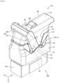
FIG. 1 is a perspective view showing a state in which a lever of a female connector according to an embodiment is disposed at a fitting start position. -
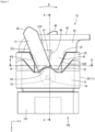
FIG. 2 is a side view showing a state in which the lever of the female connector according to the embodiment is disposed at the fitting start position. -
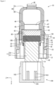
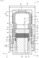
FIG. 3 is a cross-sectional view taken along the line A-A inFIG. 2 . -
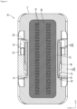
FIG. 4 is a cross-sectional view taken along the line B-B inFIG. 2 . -
FIG. 5 is an enlarged cross-sectional view showing a principal part ofFIG. 4 . -
FIG. 6 is a perspective view showing a state in which the lever of the female connector according to the embodiment is disposed at a fitting completion position. -
FIG. 7 is a side view showing a state in which the lever of the female connector according to the embodiment is disposed at the fitting completion position. -
FIG. 8 is a cross-sectional view taken along the line C-C inFIG. 7 . -
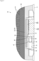
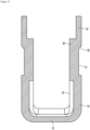
FIG. 9 is an enlarged cross-sectional views showing a principal part, taken along the line D-D inFIG. 7 . -
FIG. 10 is a perspective view of an outer housing according to an embodiment. -
FIG. 11 is a perspective view of the outer housing according to the embodiment, as viewed from the rear side. -
FIG. 12 is a rear view of the outer housing according to the embodiment. -
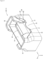
FIG. 13 is a perspective view of a wire cover according to an embodiment. -
FIG. 14 is a side view of the wire cover according to the embodiment. -
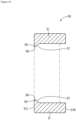
FIG. 15 is a cross-sectional view taken along the line E-E inFIG. 14 . -
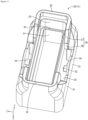
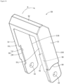
FIG. 16 is a perspective view of a lever according to an embodiment. -
FIG. 17 is a side view of the lever of the embodiment. -
FIG. 18 is a cross-sectional view taken along the line F-F inFIG. 17 . -
- (1) A technique disclosed by the present specification relates to a lever-type connector including: a connector housing configured to be fittable to a counterpart connector, and including a terminal housing part that houses a terminal; a plate-shaped sealing member configured to be abutted against a rear surface of the terminal housing part inside the connector housing, and to allow a wire connected to the terminal to pass therethrough; a wire cover configured to be mounted to the connector housing, and to cover the wire that is pulled out from the connector housing; and a lever configured to be mounted to the connector housing, and to be pivotable from a fitting start position to a fitting completion position, wherein the wire cover includes outer covering parts that cover, from the outside, the connector housing at least at a part of a portion of the connector housing in which the sealing member is housed, the lever includes two leg parts, and an operation part that connects the two leg parts, and the leg parts are configured to overlap outer sides of the corresponding outer covering parts in a state in which at least the lever is disposed at the fitting completion position, protrusions protruding toward the corresponding outer covering parts are provided on inner surfaces of the corresponding leg parts at portions that overlap the corresponding outer covering parts in a state in which the lever is disposed at the fitting completion position, and the protrusions each include an inclined pressing surface that is inclined in a pivot progression direction in which the lever pivots from the fitting start position toward the fitting completion position, and inclined pressed surfaces that are inclined toward an opposite side in the pivot progression direction, and against which the corresponding inclined pressing surfaces are abutted are provided on outer surfaces of the corresponding outer covering parts at portions where the inclined pressing surfaces are disposed in a state in which the lever is disposed at the fitting completion position.
- With the aforementioned configuration, even if the sealing member through which the wire is passed bulges outward in the radial direction in a state in which the lever is disposed at the fitting completion position, and a force is exerted in a direction (outward) to cause the connector housing to bulge, the connector housing is pressed inward by the outer covering parts of the wire cover and the leg parts of the lever that overlap the outer surface of the connector housing, whereby bulging of the connector housing is suppressed.
- Moreover, the protrusions provided on the leg parts of the lever reliably press the connector housing via the outer covering parts with a partially strong force. Accordingly, it is possible to more reliably suppress deformation (bulging) of the connector housing as compared with a configuration in which the lever includes no protrusions.
- In addition, the inclined pressing surfaces provided on the protrusions of the lever are abutted against the corresponding inclined pressed surfaces provided on the wire cover upon completion of fitting. Accordingly, the provision of the protrusions does not significantly increase the fitting force required during pivoting as compared with a configuration in which no protrusions are provided. On the other hand, in a state in which the lever is disposed at the fitting completion position, the inclined pressing surfaces and the inclined pressed surfaces have already abutted against each other. Accordingly, even if a force is exerted on the connector housing in a bulging direction, deformation of the connector housing is suppressed, and the connector housing is pressed inward with a partially strong force.
- Moreover, the inclined pressing surfaces and the corresponding inclined pressed surfaces can overlap each other by moving over each other until a clearance formed between the lever and the wire cover is filled. Accordingly, it is possible to more reliably suppress deformation of the connector housing.
- (2) A pivot allowing part for allowing pivoting of each of the protrusions may be formed on the corresponding outer covering part by cutting out a portion of an outer surface side of the outer covering part, along a pivot trajectory along which the protrusion pivots when the lever pivots between the fitting start position and the fitting completion position, and each of the inclined pressed surfaces may be constituted by a cut-out edge portion formed by cutting out a portion of the corresponding pivot allowing part.
- With the aforementioned configuration, it is possible to realize an embodiment of a configuration in which the lever does not interfere with the wire cover when being pivoted from the fitting start position to the fitting completion position, and the inclined pressing surfaces of the protrusions abut against the corresponding inclined pressed surfaces of the wire cover at the time when the lever is disposed at the fitting completion position. Accordingly, it is possible to prevent a frictional force generated as a result of the lever coming into slidable contact with the wire cover while pivoting from being added to the fitting force.
- (3) The inclined pressed surfaces may be provided at a central portion of the wire cover in a length direction of the connector housing.
- With the aforementioned configuration, it is possible to more effectively suppress deformation of the connector housing.
- (4) The lever-type connector may further include a lock part that restricts pivoting of the lever toward the fitting start position in a state in which the lever is disposed at the fitting completion position.
- With the aforementioned configuration, it is possible to avoid a situation where bulging of the connector housing causes the lever to be pressed back toward the fitting start position, thus enabling the connector housing to be continuously pressed inward in a reliable manner.
- Specific examples of the technique disclosed by the present specification will be described below with reference to the drawings. It should be noted that the technique disclosed by the present specification is not limited to these examples, but is defined by the claims, and is intended to include all modifications which fall within the scope of the claims and the meaning and scope of equivalents thereof.
- An embodiment will be described with reference to
FIGS. 1 to 18 . In the following description, the X direction shown in the drawings is the forward direction, and the direction opposite thereto is the rearward direction. In addition, the Y direction is the rightward direction, and the direction opposite thereto is the leftward direction. Furthermore, the description will be given taking a direction extending along the Y direction as the length direction, and a direction extending along the Z direction as the width direction. For the sake of convenience, a female terminal and a wire may not be shown. - A lever-type connector according to the present embodiment is a
female connector 10 configured to be fitted to a male connector 100 (an exemplary counterpart connector). Thefemale connector 10 includes a housing (an exemplary connector housing) 11 that holds afemale terminal 70 to which an end of a wire W is connected, awire cover 40 configured to be mounted to thehousing 11, and alever 50 also configured to be mounted to thehousing 11. - The
housing 11 is made of a synthetic resin, and as shown inFIGS. 3 and8 , includes an inner housing (an exemplary terminal housing part) 12 that holds thefemale terminal 70, and anouter housing 20 that holds theinner housing 12 thereinside. - As shown in
FIGS. 3 and8 , theinner housing 12 has a substantially rectangular block shape, and has a plurality of cavities (not shown) extending therethrough in the front-rear direction. Each of the cavities is configured to house afemale terminal 70 and an end portion of a wire W connected to thefemale terminal 70. - As shown in
FIGS. 3 and8 , a sealingmember 60 is attached to a back surface (an exemplary rear surface) 12B of theinner housing 12. The sealingmember 60 has a plate shape, and is made of an elastic material such as rubber. The sealingmember 60 includes, at its positions corresponding to openings of the plurality of cavities of theinner housing 12, a plurality of sealing member-side wire throughholes 61 for passing a plurality of wires W therethrough (seeFIG. 4 , etc.). The sealingmember 60 realizes waterproofing on theback surface 12B side of theinner housing 12. - Additionally, as shown in
FIGS. 3 and8 , arear holder 63 for holding the sealingmember 60 in theinner housing 12 is provided on the back surface of the sealingmember 60. Therear holder 63 is made of a synthetic resin, and has a plate shape. Therear holder 63 has, at its positions corresponding to the sealing member-side wire throughholes 61, holder-side wire through holes (not shown) for passing the wires W therethrough. That is, the cavities of theinner housing 12, the sealing member-side wire throughholes 61, and the holder-side wire through holes are in communication with one another in the front-rear direction. - On the other hand, the
outer housing 20 has an overall substantially rectangular tubular shape, as shown inFIGS. 10 to 12 . Theouter housing 20 includes aninner holding wall 21, aholder holding wall 23, acover holding wall 25, alever holding wall 31, and twopivot shafts 34. - The
inner holding wall 21 has a substantially rectangular tubular shape, and is configured to house theinner housing 12 thereinside. As shown inFIGS. 3 and8 , the length dimension of theinner holding wall 21 in the front-rear direction (X direction) is set to be slightly shorter than the length dimension of theinner housing 12 in the same direction (X direction). Theinner housing 12 is held by theinner holding wall 21 such that theback surface 12B thereof is flush with a rear end of theinner holding wall 21, and that a front end thereof protrudes past a front end of theinner holding wall 21. - As also shown in
FIGS. 3 and8 , theholder holding wall 23 has a substantially rectangular tubular shape whose size increases from theinner holding wall 21 via a housing-side steppedpart 22 at the rear of theinner holding wall 21. Inside theholder holding wall 23, the sealingmember 60 is housed in abutment against theback surface 12B of theinner housing 12, and therear holder 63 is housed in abutment against the back surface of the sealingmember 60. Theholder holding wall 23 is set to a size such that therear holder 63 does not protrude past the rear end thereof. - In addition, a ring-shaped second sealing
member 65 made of an elastic material is attached to a corner portion of an outer surface of the housing-side steppedpart 22 between theinner holding wall 21 and theholder holding wall 23. - As shown in
FIG. 10 and so forth, thecover holding wall 25 overlaps an outer circumference of theholder holding wall 23 so as to surround theholder holding wall 23, and protrudes further rearward from the rear end of theholder holding wall 23. Of thecover holding wall 25, a pair of walls extending in the longitudinal direction (left-right direction, Y direction) are receivingparts 26 formed by cutting out a portion of thecover holding wall 25 from a central portion of the rear end toward the front side. Specifically, the receivingparts 26 each include aninclined portion 27 that is inclined forward from the rear end of thecover holding wall 25 so as to approach each other, andparallel portions 28 that extend parallel to each other continuously from the correspondinginclined portions 27 to a front end of thecover holding wall 25. Thecover holding wall 25 is divided in two in the left-right direction by the receivingparts 26. - The
lever holding wall 31 is provided so as to surround an outer circumference of theinner holding wall 21 via a space interposed therebetween. A rear end of thelever holding wall 31 is connected to thecover holding wall 25. Accordingly, a frame-shaped space surrounded by thelever holding wall 31 and theinner holding wall 21 is open forward, thus forming a fitting space S1 in which ahood part 102, which will be described later, of themale connector 100 can be received (seeFIG. 3 ). - Two wall portions of the
lever holding wall 31 that extend in the longitudinal direction (left-right direction, Y direction) have a thickness that is set to be larger than those of the other wall portions. Of each of the two wall portions of thelever holding wall 31 that extend in the longitudinal direction, a central portion corresponding to the portion at which theparallel portions 28 of thecover holding wall 25 are formed is formed as arecess 32 that is recessed outward from the inner surface (seeFIGS. 11 and12 ). Therecess 32 has a groove shape that extends in the front-rear direction (X direction). In other words, thelever holding wall 31 bulges outward in a substantially gate shape from theinner holding wall 21 in the longitudinal direction thereof. - As shown in
FIG. 10 and so forth, a semi-circularpivoting restriction part 33 extends rearward in regions of thelever holding wall 31 where therecesses 32 are formed in the left-right direction (Y direction). The pivotingrestriction part 33 is a portion that restricts the pivoting range of thelever 50, which will be described later. The rear end of the pivotingrestriction part 33 extends to a position at which the sealingmember 60 is disposed in the front-rear direction of the housing 11 (seeFIG. 3 ). - The space between an outer surface of the
inner holding wall 21 and an inner surface of each of therecesses 32 of thelever holding wall 31 serves as a lever housing part S2 in which aleg part 51, which will be described later, of thelever 50 is housed (seeFIG. 12 ). - Additionally, as shown in
FIGS. 11 and12 , apivot shaft 34 that protrudes toward theinner holding wall 21 is provided on the inner surface of each of therecesses 32 of thelever holding wall 31. Thepivot shaft 34 is a columnar shaft for pivotably supporting thelever 50. - The
wire cover 40 is a member that is mounted to thehousing 11 so as to cover the back surface (the surface on therear holder 63 side) in order to protect the wire W led out from theinner housing 12, and to lead the wire W in a predetermined direction. Thewire cover 40 is made of a synthetic resin, and has a substantially box shape that is open at the front and on the right side, as shown inFIGS. 13 and14 . Hereinafter, a wall that extends in the left-right direction so as to cover the back surface of thehousing 11 is referred to as amain wall 41, and two walls that extend forward from side edge portions of themain wall 41 and oppose each other are referred to asside walls 42. One end side (left side) of themain wall 41 is curved forward, and is continuous with left edge portions of theside walls 42. - An extending wall part (an exemplary outer covering part) 43 that extends forward extends from a central front end of each of the
side walls 42 in the longitudinal direction (left-right direction, Y direction). As shown inFIG. 14 , the extendingwall part 43 has a tapered, substantially trapezoidal shape. In a state in which thewire cover 40 is mounted to thehousing 11, left and right side edge portions of the extendingwall part 43 are inclined at an angle at which the side edge portions are substantially tightly fitted to the corresponding receiving parts 26 (inclined portions 27) of the cover holding wall 25 (seeFIGS. 2 and7 ). - The inclination angles and positions of the side edges of the extending
wall parts 43 and the receiving parts 26 (inclined portions 27) are set such that the extendingwall parts 43 include the entire pivot trajectory, which will be described later, of thelever 50. More specifically, a leftside edge portion 43L of each of the extendingwall parts 43 according to the present embodiment is set at an inclination angle and a position at which the extendingwall part 43 includes a leftside edge portion 51L of thecorresponding leg part 51 of thelever 50 at a fitting start position (seeFIG. 2 ), and a rightside edge portion 43R of the extendingwall part 43 is set at an inclination angle and a position at which the extendingwall part 43 includes a rightside edge portion 51R of theleg part 51 of thelever 50 at a fitting completion position (seeFIG. 7 ). - The extending
wall parts 43 are disposed on the outer circumference of theholder holding wall 23 in a state in which thewire cover 40 is mounted to thehousing 11. That is, the extendingwall parts 43 are disposed at positions at which the extendingwall parts 43 cover, from the outside, a portion of thehousing 11 in which the sealingmember 60 is housed (seeFIGS. 3 and7 ). - Fitting
wall parts 45 extending inward and forward in a crank shape from the twoside walls 42 via a cover-side steppedpart 44 are provided at front end portions of the twoside walls 42 of thewire cover 40, excluding extended proximal end portions of the extendingwall parts 43 and the extendingwall parts 43. Thefitting wall parts 45 are portions that are fitted inside thecover holding wall 25 so as to hold thewire cover 40 with respect to thehousing 11. - A cantilevered elastic locking piece (an exemplary lock part) 46 that protrudes rearward is provided on the
main wall 41 of thewire cover 40. As shown inFIG. 1 , theelastic locking piece 46 is formed by cutting and bending a portion of themain wall 41 from the left side toward the right side into a U-shape, and is configured to be elastically deformable in a direction intersecting the plate surface of themain wall 41. As a result of a right end portion of theelastic locking piece 46 abutting against, from the left side, an operation part 52 (an exemplary lock part) of thelever 50 at the fitting completion position (seeFIG. 6 ), thelever 50 is restricted from pivoting from the fitting completion position toward the fitting start position. - The
lever 50 is a member for assisting fitting and separation between thefemale connector 10 and themale connector 100. Thelever 50 is made of a synthetic resin, and is pivotably mounted to the housing 11 (outer housing 20), as shown inFIGS. 1 ,6 , and so forth. - As shown in
FIGS. 16 to 18 , thelever 50 includes twoleg parts 51, and theoperation part 52 that connects one end sides of the twoleg parts 51 to each other. - Each of the two
leg parts 51 has an elongated plate shape. Ashaft hole 53, which is a circular hole, is provided on a distal end side (end portion on a side opposite to the operation part 52) of each of the twoleg parts 51. The shaft holes 53 are holes into which thepivot shafts 34 of thehousing 11 are inserted. - As shown in
FIGS. 3 to 5 , andFIGS. 8 and9 , the twoleg parts 51 are housed in the corresponding two lever housing parts S2. A distal end side of an outer surface of each of theleg parts 51 is disposed along thelever holding wall 31. The inner surface of theleg part 51 is disposed along theinner holding wall 21 and thewire cover 40. - The
lever 50 is pivotable, about thepivot shafts 34 serving as the pivot center, between the fitting start position (position shown inFIGS. 1 and2 ) and the fitting completion position (position shown inFIGS. 6 and7 ). When located at the fitting start position, thelever 50 is orientated so as to be inclined obliquely to the left relative to theleft side housing 11. When located at the fitting completion position, thelever 50 is oriented so as to be inclined obliquely to the right relative to thehousing 11. - The outer surface of each of the leg parts 5 is provided with a stepped
restriction receiving part 54 that is disposed along an end face of the correspondingpivoting restriction part 33 of thelever holding wall 31 when thelever 50 is pivoted (seeFIGS. 16 and17 ). Therestriction receiving part 54 is formed by arcuately cutting out, in the plate thickness direction, a portion of the outer surface that is located toward a distal end portion of theleg part 51. Thelever 50 is allowed to pivot only within a range in which therestriction receiving parts 54 are disposed along the corresponding pivotingrestriction parts 33. - As shown in
FIG. 3 , the male connector 100 (an exemplary counterpart connector) includes abottom plate part 101, and atubular hood part 102 that extends from thebottom plate part 101.Male terminals 103 that are to be connected to thefemale terminals 70 held in theinner housing 12 are held in themale connector 100. - Although not shown, gear receiving parts corresponding to gear parts (not shown) respectively included in the two
leg parts 51 of thelever 50 are provided on an outer surface of thehood part 102. The fitting between themale connector 100 and thefemale connector 10 is achieved by a camming action between the gear parts and the gear receiving parts caused by a pivoting operation of thelever 50. - As shown in
FIGS. 16 to 18 , in thelever 50 according to the present embodiment, pressing ribs (exemplary protrusions) 55 are provided on the respective inner surfaces (surfaces opposed to each other) of the twoleg parts 51. Each of thepressing ribs 55 is provided at a portion of thewire cover 40 where it overlaps the corresponding extendingwall part 43 in a state in which thelever 50 is disposed at the fitting completion position (seeFIG. 7 ). That is, thepressing rib 55 is provided on the distal end side relative to a central portion of thecorresponding leg part 51 in the length direction. - Specifically, as shown in
FIGS. 16 to 18 , each of thepressing ribs 55 extends linearly along a leftside edge portion 51L (end portion located on the fitting start position side) of the inner surface of thecorresponding leg part 51 of thelever 50. In other words, thepressing rib 55 extends linearly, in a direction intersecting a pivot progression direction D in which thelever 50 pivots from the fitting start position toward the fitting completion position, at an opposite end portion of the inner surface of theleg part 51 of thelever 50 in the pivot progression direction D. - Of each of these
pressing ribs 55, a corner portion located on the pivot progression direction D side of thelever 50 is formed as a rib-side inclined surface (an exemplary inclined pressing surface) 57 that is cut out obliquely. As shown inFIG. 18 , each of the rib-side inclined surfaces 57 is inclined continuously to a plate surface (inner surface) of thecorresponding leg part 51, from atop surface 56 of thepressing rib 55 in the pivot progression direction D. - Note that a front end (lower end in
FIG. 17 ) of each of thepressing ribs 55 extends to a position that includes the front end of the corresponding extendingwall part 43 in a state in which thelever 50 is mounted to the housing 11 (seeFIGS. 2 and7 ). That is, the front end extends to a position in close proximity to thepivot shaft 34. A rear end (upper end inFIG. 17 ) of thepressing rib 55 extends to a position that includes the outer circumference of the sealingmember 60 in a state in which thelever 50 is mounted to thehousing 11. - On the other hand, a
pivot allowing part 47 is formed on each of theside walls 42 and the extendingwall parts 43 of thewire cover 40 by partially cutting out the outer surface side of theside wall 42 and the extendingwall part 43 to allow pivoting of the correspondingpressing rib 55, along a pivot trajectory along which thepressing rib 55 pivots as a result of pivoting of thelever 50. In the present embodiment, as shown inFIGS. 13 and14 , thepivot allowing part 47 has a fan shape that is cut out from the leftside edge portion 43L of the extendingwall part 43 toward the right side. - In a state in which the
lever 50 is disposed at the fitting completion position, a portion on which the rib-sideinclined surface 57 of each of thepressing ribs 55 is disposed, or in other words, a cut-out edge portion of the right end of the correspondingpivot allowing part 47 is a cover-side inclined surface (an exemplary inclined pressed surface) 48 that is to overlap the rib-sideinclined surface 57. That is, as shown inFIG. 15 , the cover-sideinclined surface 48 is inclined toward the opposite side of thelever 50 in the pivot progression direction D. The cover-sideinclined surface 48 is disposed at a substantially central portion of thewire cover 40 in the longitudinal direction (left-right direction, Y direction) of thehousing 11. - Next, an exemplary procedure for fitting the
female connector 10 having the above-described configuration to themale connector 100 will be described below. First, as shown inFIGS. 1 and2 , in a state in which thelever 50 is held at the fitting start position, thehousing 11 of thefemale connector 10 is loosely fitted to themale connector 100, and a distal end portion of thehood part 102 enters the fitting space S1. In a state in which thelever 50 is disposed at the fitting start position, thepressing ribs 55 of thelever 50 are disposed in the correspondingpivot allowing parts 47 of thewire cover 40, and thus thepressing ribs 55 and thewire cover 40 do not interfere with each other. - Next, the
lever 50 is pivoted in the pivot progression direction D from the fitting start position toward the fitting completion position. During this pivoting, thepressing ribs 55 move along thepivot allowing parts 47, and therefore thepressing ribs 55 and thewire cover 40 do not interfere with each other. As a result of pivoting of thelever 50, thehousing 11 is relatively drawn toward themale connector 100 by a camming action (not shown), whereby fitting proceeds. - After fitting between the
female connector 10 and themale connector 100 has proceeded, and thelever 50 reaches the fitting completion position as shown inFIGS. 6 and7 , thehousing 11 reaches a normal fitting position relative to themale connector 100. Immediately before thelever 50 reaches the fitting completion position, theoperation part 52 of thelever 50 abuts against theelastic locking piece 46 of thewire cover 40 to gradually depress theelastic locking piece 46, and moves over theelastic locking piece 46 upon reaching the fitting position. Thus, theelastic locking piece 46 is elastically restored, and locks to a surface of theoperation part 52 of thelever 50 that is located on the opposite side in the pivot progression direction D. Accordingly, the pivoting of thelever 50 to the opposite side in the pivot progression direction D is restricted, and thelever 50 is locked to the fitting position. - In this locked state, as shown in
FIG. 9 , the rib-sideinclined surface 57 of each of thepressing ribs 55 provided on theleg parts 51 of thelever 50 overlaps with the corresponding cover-sideinclined surface 48 of thewire cover 40 so as to move thereon, and presses the cover-sideinclined surface 48 in a direction intersecting the cover-sideinclined surface 48. At this time, thetop surface 56 of thepressing rib 55 is in proximity to or abuts against the correspondingpivot allowing part 47. That is, at least through abutment between the inclined surfaces, the extendingwall parts 43 of thewire cover 40 are pressed inward by thepressing ribs 55 of thelever 50. Accordingly, the holder holding wall 23 (outer housing 20) is pressed inward by the extendingwall parts 43, and thus is less likely to bulge outward. - In this manner, the fitting between the
female connector 10 and themale connector 100 is completed. - As described above, the female connector 10 according to the present embodiment includes: a housing 11 configured to be fittable to a male connector 100, and including an inner housing 12 that houses a terminal; a plate-shaped sealing member 60 configured to be abutted against a back surface 12B of the inner housing 12 inside the housing 11, and to allow a wire W connected to the terminal to pass therethrough; a wire cover 40 configured to be mounted to the housing 11, and to cover the wire W that is pulled out from the housing 11; and a lever 50 configured to be mounted to the housing 11, and to be pivotable from a fitting start position to a fitting completion position, wherein the wire cover 40 includes extending wall parts 43 that cover, from the outside, the housing 11 at a part of a portion thereof in which the sealing member 60 is housed, the lever 50 includes two leg parts 51, and an operation part 52 that connects the two leg parts 51, the leg parts 51 are configured to overlap outer sides of the corresponding extending wall parts 43 in a state in which the lever 50 is disposed at the fitting completion position, pressing ribs 55 protruding toward the corresponding extending wall parts 43 are provided on inner surfaces of the corresponding leg parts 51 at portions that overlap the corresponding extending wall parts 43 in a state in which the lever 50 is disposed at the fitting completion position, the pressings rib 55 each have a rib-side inclined surface 57 that is inclined toward a pivot progression direction D in which the lever 50 pivots from the fitting start position toward the fitting completion position, and rib-side inclined surfaces 57 that are inclined toward an opposite side in the pivot progression direction D, and against which the corresponding cover-side inclined surfaces 48 are abutted are provided on outer surfaces of the corresponding extending wall parts 43 at portions where the rib-side inclined surfaces 57 are disposed in a state in which the lever 50 is disposed at the fitting completion position.
- With such a configuration, even if the sealing
member 60 through which the wire W is passed bulges outward in the radial direction in a state in which thelever 50 is disposed at the fitting completion position, and a force is exerted in a direction (outward) to cause the housing 11 (outer housing 20) to bulge, thehousing 11 is pressed inward by the extendingwall parts 43 of thewire cover 40 and theleg parts 51 of thelever 50 that overlap the outer surface of thehousing 11. Thus, bulging of thehousing 11 is suppressed. - Moreover, the
pressing ribs 55 provided on theleg parts 51 of thelever 50 reliably press the holder holding wall 23 (outer housing 20) via the extendingwall parts 43 with a partially strong force. Accordingly, it is possible to more reliably suppress deformation (bulging) of thehousing 11 as compared with a configuration in which thelever 50 includes nopressing ribs 55. - In addition, the rib-side inclined surfaces 57 provided on the
pressing ribs 55 of thelever 50 are abutted against the corresponding cover-side inclined surfaces 48 provided on thewire cover 40 upon completion of fitting. Accordingly, the provision of thepressing ribs 55 does not significantly increase the fitting force required during pivoting as compared with a configuration in which nopressing ribs 55 are provided. On the other hand, in a state in which thelever 50 is disposed at the fitting completion position, the rib-side inclined surfaces 57 and the cover-side inclined surfaces 48 have already been abutted against each other. Accordingly, even if a force is exerted on thehousing 11 in a bulging direction, deformation of the holder holding wall 23 (outer housing 20) is suppressed, and the housing 11 (outer housing 20) is pressed inward with a partially strong force. - Moreover, the rib-side inclined surfaces 57 and the corresponding cover-side inclined surfaces 48 can overlap each other by moving over each other until a clearance formed between the
lever 50 and thewire cover 40 is filled. Accordingly, it is possible to more reliably suppress deformation of theouter housing 20. - A
pivot allowing part 47 for allowing pivoting of each of thepressing ribs 55 is formed on the corresponding extendingwall part 43 by cutting out a portion of an outer surface of the extendingwall part 43, along a pivot trajectory along which thepressing rib 55 pivots when thelever 50 pivots between the fitting start position and the fitting completion position, and each of the cover-side inclined surfaces 48 is constituted by a cut-out edge portion formed by cutting out a portion of the correspondingpivot allowing part 47. - With the aforementioned configuration, it is possible to realize an embodiment of a configuration in which the
lever 50 does not interfere with thewire cover 40 when being pivoted from the fitting start position to the fitting completion position, and the rib-side inclined surfaces 57 of thepressing ribs 55 abut against the corresponding cover-side inclined surfaces 48 of thewire cover 40 at the time when thelever 50 is disposed at the fitting completion position. Accordingly, thelever 50 does not come into slidable contact with thewire cover 40 while pivoting, and it is possible to prevent a frictional force generated by thelever 50 and the wire cover 40 from being added to the fitting force. - The cover-side inclined surfaces 48 are provided at a central portion of the
wire cover 40 in the length direction of thehousing 11. With such a configuration, the central portion in the length direction of thehousing 11, which is likely to undergo significant deformation as compared with other portions, can be pressed inward, and it is therefore possible to more effectively suppress deformation of thehousing 11. - An
elastic locking piece 46 that restricts pivoting of thelever 50 toward the fitting start position by locking to thelever 50 in a state in which thelever 50 is disposed at the fitting completion position is provided on thewire cover 40. - With the aforementioned configuration, it is possible to avoid a situation where bulging of the
housing 11 causes thelever 50 to be pressed back toward the fitting start position, thus enabling the housing 11 (outer housing 20) to be continuously pressed inward in a reliable manner. - In this manner, with the
female connector 10 according to the present embodiment, it is possible to suppress bulging of the housing 11 (outer housing 20) caused by the sealingmember 60, and suppress a reduction in waterproofness due to plastic deformation. -
- (1) The above embodiment has described a configuration in which each of the
pressing ribs 55 is provided at an end portion on the opposite side in the pivot progression direction D of thecorresponding leg part 51 of thelever 50. However, the portion at which the pressing rib is provided is not limited to an end portion on the opposite side in the pivot progression direction, and it is also possible to adopt a configuration in which the pressing rib is provided at another portion. - (2) Although the above embodiment has described a configuration in which each of the protrusions is in the form of a rib, the protrusion is not limited to a rib, and may have another configuration. For example, it is also possible to arrange many short protrusions side-by-side.
- (3) The above embodiment has described a configuration in which the cover-side inclined surfaces 48 are provided at a substantially central portion of the
housing 11 in the length direction. However, it is also possible to adopt a configuration in which the inclined pressed surfaces are provided at a position toward an end of the housing in the length direction. - (4) Although the above embodiment has described a configuration in which the
inner housing 12 and theouter housing 20 are formed by separate members, the inner housing and the outer housing may be formed by one member. - (5) The configuration of the lock part is not limited to the above embodiment.
- (6) The inclined pressed surface is not limited to a configuration constituted by a cut-out edge portion of the pivot allowing part, and can also be formed, for example, by cutting out a corner portion of a protrusion similar to the pressing rib that protrudes from an external covering part disposed so as to be spaced apart from the inner surface of the lever.
- (7) The above embodiment has described a configuration in which the
pressing ribs 55 each have a trapezoidal cross-sectional shape that includes a flattop surface 56 and a rib-sideinclined surface 57, as shown inFIG. 18 . However, it is also possible to adopt a configuration in which the pressing ribs each have a triangular cross-sectional shape that does not include a flat top surface. -
- 10
- Female connector
- 11
- Housing (connector housing)
- 12
- Inner housing (terminal housing part)
- 12B
- Back surface (rear surface)
- 20
- Outer housing (connector housing)
- 21
- Inner holding wall
- 22
- Housing-side stepped part
- 23
- Holder holding wall
- 25
- Cover holding wall
- 26
- Receiving part
- 27
- Inclined portion
- 28
- Parallel portion
- 31
- Lever holding wall
- 32
- Recess
- 33
- Pivoting restriction part
- 34
- Pivot shaft
- 40
- Wire cover
- 41
- Main wall
- 42
- Side wall
- 43
- Extending wall part (outer covering part)
- 43L
- Left side edge portion
- 43R
- Right side edge portion
- 44
- Cover-side stepped part
- 45
- Fitting wall part
- 46
- Elastic locking piece (lock part)
- 47
- Pivot allowing part
- 48
- Cover-side inclined surface (inclined pressed surface)
- 50
- Lever
- 51
- Leg part
- 51L
- Left side edge portion
- 51R
- Right side edge portion
- 52
- Operation part (lock part)
- 53
- Shaft hole
- 54
- Restriction receiving part
- 55
- Pressing rib (protrusion)
- 56
- Top surface
- 57
- Rib-side inclined surface (inclined pressing surface)
- 60
- Sealing member
- 61
- Sealing member-side wire through hole
- 63
- Rear holder
- 65
- Second sealing member
- 70
- Female terminal (terminal)
- 85A
- Guide receiving part
- 100
- Male connector
- 101
- Bottom plate part
- 102
- Hood part
- 103
- Male terminal
- D
- Pivot progression direction
- S1
- Fitting space
- S2
- Lever housing part
- W
- Wire
Claims (4)
- A lever-type connector comprising:a connector housing configured to be fittable to a counterpart connector, and including a terminal housing part that houses a terminal;a plate-shaped sealing member configured to be abutted against a rear surface of the terminal housing part inside the connector housing, and to allow a wire connected to the terminal to pass therethrough;a wire cover configured to be mounted to the connector housing, and to cover the wire that is pulled out from the connector housing; anda lever configured to be mounted to the connector housing, and to be pivotable from a fitting start position to a fitting completion position,wherein the wire cover includes outer covering parts that cover, from the outside, the connector housing at least at a part of a portion of the connector housing in which the sealing member is housed,the lever includes two leg parts, and an operation part that connects the two leg parts, and the leg parts are configured to overlap outer sides of the corresponding outer covering parts in a state in which at least the lever is disposed at the fitting completion position,protrusions protruding toward the corresponding outer covering parts are provided on inner surfaces of the corresponding leg parts at portions that overlap the corresponding outer covering parts in a state in which the lever is disposed at the fitting completion position, and the protrusions each include an inclined pressing surface that is inclined in a pivot progression direction in which the lever pivots from the fitting start position toward the fitting completion position, andinclined pressed surfaces that are inclined toward an opposite side in the pivot progression direction, and against which the corresponding inclined pressing surfaces are abutted are provided on outer surfaces of the corresponding outer covering parts at portions where the inclined pressing surfaces are disposed in a state in which the lever is disposed at the fitting completion position.
- The lever-type connector according to claim 1,wherein a pivot allowing part for allowing pivoting of each of the protrusions is formed on the corresponding outer covering part by cutting out a portion of an outer surface side of the outer covering part, along a pivot trajectory along which the protrusion pivots when the lever pivots between the fitting start position and the fitting completion position, andeach of the inclined pressed surfaces is constituted by a cut-out edge portion formed by cutting out a portion of the corresponding pivot allowing part.
- The lever-type connector according to claim 1 or 2,
wherein the inclined pressed surfaces are provided at a central portion of the wire cover in a length direction of the connector housing. - The lever-type connector according to any one of claims 1 to 3, further comprising
a lock part that restricts pivoting of the lever toward the fitting start position in a state in which the lever is disposed at the fitting completion position.
Applications Claiming Priority (2)
| Application Number | Priority Date | Filing Date | Title |
|---|---|---|---|
| JP2021049778A JP7444117B2 (en) | 2021-03-24 | 2021-03-24 | lever type connector |
| PCT/JP2022/009947 WO2022202288A1 (en) | 2021-03-24 | 2022-03-08 | Lever-type connector |
Publications (2)
| Publication Number | Publication Date |
|---|---|
| EP4318817A1 true EP4318817A1 (en) | 2024-02-07 |
| EP4318817A4 EP4318817A4 (en) | 2024-08-21 |
Family
ID=83397078
Family Applications (1)
| Application Number | Title | Priority Date | Filing Date |
|---|---|---|---|
| EP22775082.5A Pending EP4318817A4 (en) | 2021-03-24 | 2022-03-08 | LEVER CONNECTORS |
Country Status (5)
| Country | Link |
|---|---|
| US (1) | US12512621B2 (en) |
| EP (1) | EP4318817A4 (en) |
| JP (1) | JP7444117B2 (en) |
| CN (1) | CN116941143B (en) |
| WO (1) | WO2022202288A1 (en) |
Families Citing this family (3)
| Publication number | Priority date | Publication date | Assignee | Title |
|---|---|---|---|---|
| JP7869957B2 (en) * | 2022-10-20 | 2026-06-04 | 住友電装株式会社 | Lever-type connector |
| JP2024090737A (en) * | 2022-12-23 | 2024-07-04 | 住友電装株式会社 | Lever-type connector |
| JP2025182949A (en) * | 2024-06-04 | 2025-12-16 | 株式会社やまびこ | Work equipment |
Family Cites Families (16)
| Publication number | Priority date | Publication date | Assignee | Title |
|---|---|---|---|---|
| JP3278042B2 (en) * | 1996-09-02 | 2002-04-30 | 住友電装株式会社 | Lever connector |
| JP3959932B2 (en) | 2000-05-26 | 2007-08-15 | 住友電装株式会社 | Lever type connector |
| JP4039669B2 (en) | 2003-03-11 | 2008-01-30 | 住友電装株式会社 | connector |
| JP3747035B2 (en) | 2003-03-24 | 2006-02-22 | 矢崎総業株式会社 | connector |
| JP4826376B2 (en) | 2006-07-24 | 2011-11-30 | 住友電装株式会社 | Lever type connector |
| JP5555497B2 (en) | 2010-01-14 | 2014-07-23 | 矢崎総業株式会社 | Lever type connector |
| JP5500680B2 (en) | 2010-03-26 | 2014-05-21 | タイコエレクトロニクスジャパン合同会社 | Lever type electrical connector |
| JP2013246914A (en) | 2012-05-24 | 2013-12-09 | Sumitomo Wiring Syst Ltd | Lever type connector |
| JP5929829B2 (en) * | 2013-05-21 | 2016-06-08 | 住友電装株式会社 | Lever type connector |
| JP6008252B2 (en) * | 2013-08-23 | 2016-10-19 | 住友電装株式会社 | connector |
| JP6036661B2 (en) * | 2013-11-19 | 2016-11-30 | 住友電装株式会社 | Waterproof connector |
| JP2015115255A (en) * | 2013-12-13 | 2015-06-22 | タイコエレクトロニクスジャパン合同会社 | Wire cover and electrical connector |
| JP2016207416A (en) * | 2015-04-21 | 2016-12-08 | 住友電装株式会社 | connector |
| JP6438360B2 (en) * | 2015-07-10 | 2018-12-12 | モレックス エルエルシー | Connector and connector assembly |
| JP2017228442A (en) * | 2016-06-23 | 2017-12-28 | 日本圧着端子製造株式会社 | connector |
| JP6755148B2 (en) * | 2016-08-30 | 2020-09-16 | タイコエレクトロニクスジャパン合同会社 | Lever type connector |
-
2021
- 2021-03-24 JP JP2021049778A patent/JP7444117B2/en active Active
-
2022
- 2022-03-08 EP EP22775082.5A patent/EP4318817A4/en active Pending
- 2022-03-08 WO PCT/JP2022/009947 patent/WO2022202288A1/en not_active Ceased
- 2022-03-08 US US18/282,489 patent/US12512621B2/en active Active
- 2022-03-08 CN CN202280018020.4A patent/CN116941143B/en active Active
Also Published As
| Publication number | Publication date |
|---|---|
| JP7444117B2 (en) | 2024-03-06 |
| US12512621B2 (en) | 2025-12-30 |
| CN116941143A (en) | 2023-10-24 |
| WO2022202288A1 (en) | 2022-09-29 |
| JP2022148194A (en) | 2022-10-06 |
| CN116941143B (en) | 2026-07-28 |
| EP4318817A4 (en) | 2024-08-21 |
| US20240145992A1 (en) | 2024-05-02 |
Similar Documents
| Publication | Publication Date | Title |
|---|---|---|
| US12512621B2 (en) | Lever-type connector | |
| CN104885308B (en) | Water-proof connector | |
| CN102160244B (en) | Connector with lever | |
| JP4317973B2 (en) | connector | |
| EP2369691B1 (en) | Lever type electrical connector | |
| JP6424190B2 (en) | Lever type connector | |
| JP2002352903A (en) | Lever connector | |
| US9022798B2 (en) | Connector | |
| JP4748054B2 (en) | connector | |
| US9099812B2 (en) | Connector | |
| CN109066213B (en) | rod connector | |
| US10122115B2 (en) | Connector | |
| JP7410073B2 (en) | connector unit | |
| US11088491B2 (en) | Housing with lock piece | |
| JP2009104934A (en) | Connector | |
| JP4370265B2 (en) | Waterproof connector | |
| EP3896797A1 (en) | Connector | |
| JP2018206647A (en) | Lever type connector | |
| JP6916040B2 (en) | Lever type connector | |
| JP4781885B2 (en) | Waterproof connector | |
| JP5696893B2 (en) | Waterproof connector | |
| JP2021018910A (en) | connector | |
| US20250105555A1 (en) | Connector | |
| JP2017183100A (en) | Connector cover | |
| JP6892328B2 (en) | Lever type connector |
Legal Events
| Date | Code | Title | Description |
|---|---|---|---|
| STAA | Information on the status of an ep patent application or granted ep patent |
Free format text: STATUS: THE INTERNATIONAL PUBLICATION HAS BEEN MADE |
|
| PUAI | Public reference made under article 153(3) epc to a published international application that has entered the european phase |
Free format text: ORIGINAL CODE: 0009012 |
|
| STAA | Information on the status of an ep patent application or granted ep patent |
Free format text: STATUS: REQUEST FOR EXAMINATION WAS MADE |
|
| 17P | Request for examination filed |
Effective date: 20231009 |
|
| AK | Designated contracting states |
Kind code of ref document: A1 Designated state(s): AL AT BE BG CH CY CZ DE DK EE ES FI FR GB GR HR HU IE IS IT LI LT LU LV MC MK MT NL NO PL PT RO RS SE SI SK SM TR |
|
| DAV | Request for validation of the european patent (deleted) | ||
| DAX | Request for extension of the european patent (deleted) | ||
| A4 | Supplementary search report drawn up and despatched |
Effective date: 20240722 |
|
| RIC1 | Information provided on ipc code assigned before grant |
Ipc: H01R 13/56 20060101ALI20240716BHEP Ipc: H01R 13/502 20060101ALI20240716BHEP Ipc: H01R 13/629 20060101ALI20240716BHEP Ipc: H01R 13/52 20060101AFI20240716BHEP |