EP4318816A1 - Shielded and sealed connector - Google Patents
Shielded and sealed connector Download PDFInfo
- Publication number
- EP4318816A1 EP4318816A1 EP22188563.5A EP22188563A EP4318816A1 EP 4318816 A1 EP4318816 A1 EP 4318816A1 EP 22188563 A EP22188563 A EP 22188563A EP 4318816 A1 EP4318816 A1 EP 4318816A1
- Authority
- EP
- European Patent Office
- Prior art keywords
- shielding means
- electrical connector
- sealing
- housing
- shielding
- Prior art date
- Legal status (The legal status is an assumption and is not a legal conclusion. Google has not performed a legal analysis and makes no representation as to the accuracy of the status listed.)
- Granted
Links
Images

Classifications
-
- H—ELECTRICITY
- H01—ELECTRIC ELEMENTS
- H01R—ELECTRICALLY-CONDUCTIVE CONNECTIONS; STRUCTURAL ASSOCIATIONS OF A PLURALITY OF MUTUALLY-INSULATED ELECTRICAL CONNECTING ELEMENTS; COUPLING DEVICES; CURRENT COLLECTORS
- H01R13/00—Details of coupling devices of the kinds covered by groups H01R12/70 or H01R24/00 - H01R33/00
- H01R13/46—Bases; Cases
- H01R13/52—Dustproof, splashproof, drip-proof, waterproof, or flameproof cases
- H01R13/5202—Sealing means between parts of housing or between housing part and a wall, e.g. sealing rings
-
- H—ELECTRICITY
- H01—ELECTRIC ELEMENTS
- H01R—ELECTRICALLY-CONDUCTIVE CONNECTIONS; STRUCTURAL ASSOCIATIONS OF A PLURALITY OF MUTUALLY-INSULATED ELECTRICAL CONNECTING ELEMENTS; COUPLING DEVICES; CURRENT COLLECTORS
- H01R13/00—Details of coupling devices of the kinds covered by groups H01R12/70 or H01R24/00 - H01R33/00
- H01R13/46—Bases; Cases
- H01R13/502—Bases; Cases composed of different pieces
-
- H—ELECTRICITY
- H01—ELECTRIC ELEMENTS
- H01R—ELECTRICALLY-CONDUCTIVE CONNECTIONS; STRUCTURAL ASSOCIATIONS OF A PLURALITY OF MUTUALLY-INSULATED ELECTRICAL CONNECTING ELEMENTS; COUPLING DEVICES; CURRENT COLLECTORS
- H01R13/00—Details of coupling devices of the kinds covered by groups H01R12/70 or H01R24/00 - H01R33/00
- H01R13/648—Protective earth or shield arrangements on coupling devices, e.g. anti-static shielding
- H01R13/658—High frequency shielding arrangements, e.g. against EMI [Electro-Magnetic Interference] or EMP [Electro-Magnetic Pulse]
- H01R13/6581—Shield structure
-
- H—ELECTRICITY
- H01—ELECTRIC ELEMENTS
- H01R—ELECTRICALLY-CONDUCTIVE CONNECTIONS; STRUCTURAL ASSOCIATIONS OF A PLURALITY OF MUTUALLY-INSULATED ELECTRICAL CONNECTING ELEMENTS; COUPLING DEVICES; CURRENT COLLECTORS
- H01R2201/00—Connectors or connections adapted for particular applications
- H01R2201/26—Connectors or connections adapted for particular applications for vehicles
Definitions
- the present disclosure relates to the field of vehicle connectivity, and in particular but not exclusively, to the field of high-power connectivity.
- the present disclosure proposes a solution to overcome at least a partially such difficulties.
- the watertightness is ensured by using an outer shielding means onto which sealing means can be applied, in addition to its use to provide the shielding continuity between a braid and an inner shielding means.
- the connector according to the present disclosure may possibly include any of the features of claims 2 to 7, considered separately or each combined with one or more others. According to another aspect, the present disclosure relates to a connector assembly according to claim 8.
- the connector assembly according to claim 8 may possibly include any of the features of claims 9 to 13, considered separately or each combined with one or more others.
- counter-connector generally and broadly designates any element intended to be electrically connected to a connector. It can therefore be another connector, a housing on which connection components are assembled, a wall through which an electrical connection must be made, etc.
- FIG. 1 An example of an embodiment of a connector assembly 1 is illustrated in Figures 1 to 3 .
- Other embodiments of connector assemblies can be envisaged, one of which will be disclosed below in connection with Figures 4 and 5 .
- the electrical connector assembly 1 of Figures 1 to 3 comprises a connector 2, cables 100 and a shielding braid 200 (not shown in Figures 1 and 2 ).
- the connector 2 is configured for being mated to a counter-connector (not shown).
- This example of connector 2 comprises a mate assist system.
- this example of connector 2 comprises an inner housing 3, an outer shielding means 4, sealing means 5, an inner shielding means 6, gear cams 7 (for the mate assist system), a CPA device 8 ("CPA" stands for Connector Position Assurance), an outer housing 9, a ring cap 10, a plastic cap 11, a shunt 12 (for an interlock circuit which is not shown) and a slider 13 (for the mate assist system).
- CPA Connector Position Assurance
- the outer shielding means 4 is formed as a single annular band.
- the outer shielding means 4 is made of an electrically conductive material.
- the outer shielding means 4 is made of metal.
- it is a deep drawn piece, i.e. it is formed by a deep-drawing process.
- Such a deep drawn piece as the advantage of providing seamless inner and outer surfaces. This ensures more flexibility in terms of sealing material that can be used for manufacturing and mounting the sealing means 5.
- the inner 3 and outer 9 housings are made of dielectric material. For example, they are made of moulded plastics.
- the inner housing 3 comprises at least one cavity (two cavities in the example shown in the Figures). At least one conductive terminal is accommodated in each cavity. Each cavity is located in a sealed area of the connector 2.
- the inner shielding means 6 is formed as an annular band.
- the inner shielding means 6 is made of an electrically conductive material.
- the inner shielding means 6 is made of metal.
- the inner shielding means has flexible blades 14 that are protruding on the outer surface of the annular band forming the inner shielding means 6. These blades 14 are configured to make an electrical contact with the inner surface of the annular band forming the outer shielding means 4.
- the sealing means 5 is formed as a single annular band made of elastomeric material.
- the sealing means 5 has at least two ribs 15a, 15b each of which is respectively at one of its longitudinal ends (two or more ribs can be located at each longitudinal end).
- a front rib 15a is located at a front end of the sealing means 5 (i.e. close the mating interface of the connector).
- a rear rib 15b is located at a rear end of the sealing means (i.e. to a cable side of the connector 2). Between the two ribs 15, the sealing means has a central strip 16 comprising openings 17. Each opening 17 is configured to allow the passage of a blade 14.
- the sealing means 5 is mounted between the inner shielding means 6 and the outer shielding means 4.
- the front rib 15a is in sealing contact at least with the outer housing 9 and the inner surface of the outer shielding means 4.
- the rear rib 15b is in sealing contact at least with the inner housing 3 and the inner surface of the outer shielding means 4. Therefore, watertightness is provided between the inner housing 3 and the outer housing 9, with the outer shielding means 4 in between.
- a sealing barrier is formed by the outer housing 9, the front end of the sealing means 5, the outer shielding means 4, the rear end of the sealing means 5 and the inner housing 3.
- a shielding braid 200 can be mounted on the cable side of the connector 2 so as to be in electrical contact with the outer surface of the outer shielding means 4.
- the shielding braid 200 is maintained on the outer shielding means 4 with a taping 19 and a tie wrap 20.
- the taping 19 is wound around the outer housing 9 and the shielding braid 200.
- the taping 19 is placed astride the outer housing 9 and the shielding braid 200.
- the tie wrap 20 sandwiches the taping 19, the braid 200, the outer shielding means 4, possibly the sealing means 5, the inner shielding means 6 and the inner housing 3.
- FIG. 4 A further example of an embodiment of a connector assembly 1 is illustrated in Figures 4 and 5 .
- the connector 2 comprises a cap 21 for the outer shielding means 4, an outer shielding means 4, a cap 22 for an outer seal 23, an inner housing 3, an inner seal 24, an inner shielding means 6 and an outer housing 9 (mate assist elements are not shown).
- the outer shielding means 4 is formed as a single annular band.
- the outer shielding means 4 is made of an electrically conductive material.
- the outer shielding means 4 is made of metal.
- it is a deep drawn piece, i.e. it is formed by a deep-drawing process.
- Such a deep drawn piece as the advantage of providing seamless inner and outer surfaces. This ensures more flexibility in terms of sealing material that can be used for manufacturing and mounting the sealing means 5.
- the inner 3 and outer 9 housings are made of dielectric material.
- they are made of moulded plastics.
- the inner housing 3 comprises at least one cavity (two cavities in the example shown in the Figures). At least one conductive terminal is accommodated in each cavity. Each cavity is located in a sealed area of the connector 2.
- the inner shielding means 6 is formed as an annular band.
- the inner shielding means 6 is made of an electrically conductive material.
- the inner shielding means 6 is made of metal.
- the inner shielding means has flexible blades 14 that are protruding on the outer surface of the annular band forming the inner shielding means 6. These blades 14 are configured to make an electrical contact with the inner surface of the annular band forming the outer shielding means 4.
- the sealing means of this embodiment differs from the sealing means of the previous one.
- the sealing means comprises two seals: an outer seal 23 and an inner seal 24.
- these outer seal 23 and inner seal 24 are seals of the O-ring type, made of elastomeric material.
- An electrical contact is provided between the inner shielding means 6 (with elastic blades) and the inner surface of the outer shielding means 4, in a region extending longitudinally between the outer seal 23 and the inner seal 24.
- the inner seal 24 is in watertight contact with the inner surface of the outer shielding means 4 and the inner housing 3.
- the cap 21 maintains both the inner shielding means 6 and the inner seal 24 in position mounted on the inner housing 3.
- the outer seal 23 is in watertight contact with the outer surface of the outer shielding means 4 and the outer housing 3.
- the cap 22 maintains the outer seal 23 in position mounted on the outer housing 9.
- a sealing barrier is formed by the outer housing 9, the outer seal 23, the outer shielding means 4, the inner seal 24 and the inner housing 3.
- a shielding braid 200 can be mounted on the cable side of the connector 2 so as to be in electrical contact with the outer surface of the outer shielding means 4.
- the shielding braid 200 is maintained on the outer shielding means 4 with a taping 19 and a tie wrap 20.
- the taping 19 is wound around a portion of the cap 22 and the shielding braid 200.
- the taping 19 is placed astride this portion of the cap 22 and the shielding braid 200.
- the tie wrap 20 sandwiches the taping 19, the braid 200, the outer shielding means 4, the inner shielding means 6 and the inner housing 3.
Landscapes
- Connector Housings Or Holding Contact Members (AREA)
Abstract
- an inner housing (3) and an outer housing (9),
- inner shielding means (6) and outer shielding means (4), the inner shielding means (6) being in electrical contact with the outer shielding means (4),
- annular sealing means (23,24),
characterized in that the outer shielding means (4) is formed as a single annular band, the sealing means (23, 24) are in sealing contact, on the one hand, with both the outer housing (9) and the outer shielding means (4), and on the other hand with both the inner housing (3) and the outer shielding means (4).
Description
- The present disclosure relates to the field of vehicle connectivity, and in particular but not exclusively, to the field of high-power connectivity.
- When cable connectors are used in high voltage/intensity applications, it is desirable to maintain, through such cable connectors, the shielding continuity that is provided at the cable level.
- Further, it may be required to prevent humidity, salt spray, dust, etc. from entering into such cable connectors.
- However, combining both shielding continuity and watertightness raises difficulties in terms of feasibility, manufacturing, mounting, costs, etc.
- The present disclosure proposes a solution to overcome at least a partially such difficulties.
- More particularly, it is proposed an electrical connector according to
claim 1. - Indeed, the watertightness is ensured by using an outer shielding means onto which sealing means can be applied, in addition to its use to provide the shielding continuity between a braid and an inner shielding means.
- The connector according to the present disclosure may possibly include any of the features of
claims 2 to 7, considered separately or each combined with one or more others. According to another aspect, the present disclosure relates to a connector assembly according toclaim 8. - The connector assembly according to
claim 8 may possibly include any of the features ofclaims 9 to 13, considered separately or each combined with one or more others. - Further features and advantages will become apparent in the detailed discussion of various embodiments of the invention, the discussion being accompanied by examples and references to the attached drawings.
-
Figure 1 is a schematic perspective view of an embodiment example of a connector sealed and shielded connector; -
Figure 2 is a schematic perspective and exploded view of the connector shown inFigure 1 ; -
Figure 3 is a schematic longitudinal cross-section of a portion of the connector assembly comprising the connector ofFigures 1 and 2 , and a shielding braid; -
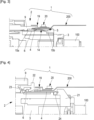
Figure 4 is a schematic longitudinal cross-section of a portion of a connector assembly according to another example of embodiment; -
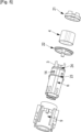
Figure 5 is a schematic perspective and exploded view of the connector of the connector assembly shown inFigure 4 . - In this document, the term "counter-connector" generally and broadly designates any element intended to be electrically connected to a connector. It can therefore be another connector, a housing on which connection components are assembled, a wall through which an electrical connection must be made, etc.
- On the figures, the same reference numbers designate identical or similar elements.
- An example of an embodiment of a
connector assembly 1 is illustrated inFigures 1 to 3 . Other embodiments of connector assemblies can be envisaged, one of which will be disclosed below in connection withFigures 4 and5 . - The
electrical connector assembly 1 ofFigures 1 to 3 comprises aconnector 2,cables 100 and a shielding braid 200 (not shown inFigures 1 and 2 ). Theconnector 2 is configured for being mated to a counter-connector (not shown). This example ofconnector 2 comprises a mate assist system. - As shown in
Figure 2 , this example ofconnector 2 comprises aninner housing 3, an outer shielding means 4, sealing means 5, an inner shielding means 6, gear cams 7 (for the mate assist system), a CPA device 8 ("CPA" stands for Connector Position Assurance), anouter housing 9, aring cap 10, aplastic cap 11, a shunt 12 (for an interlock circuit which is not shown) and a slider 13 (for the mate assist system). - The outer shielding means 4 is formed as a single annular band. The outer shielding means 4 is made of an electrically conductive material. The outer shielding means 4 is made of metal. For example, it is a deep drawn piece, i.e. it is formed by a deep-drawing process. Such a deep drawn piece as the advantage of providing seamless inner and outer surfaces. This ensures more flexibility in terms of sealing material that can be used for manufacturing and mounting the sealing means 5.
- The inner 3 and outer 9 housings are made of dielectric material. For example, they are made of moulded plastics. The
inner housing 3 comprises at least one cavity (two cavities in the example shown in the Figures). At least one conductive terminal is accommodated in each cavity. Each cavity is located in a sealed area of theconnector 2. - The inner shielding means 6 is formed as an annular band. The inner shielding means 6 is made of an electrically conductive material. The inner shielding means 6 is made of metal. The inner shielding means has
flexible blades 14 that are protruding on the outer surface of the annular band forming the inner shielding means 6. Theseblades 14 are configured to make an electrical contact with the inner surface of the annular band forming the outer shielding means 4. - The
sealing means 5 is formed as a single annular band made of elastomeric material. The sealing means 5 has at least tworibs front rib 15a is located at a front end of the sealing means 5 (i.e. close the mating interface of the connector). Arear rib 15b is located at a rear end of the sealing means (i.e. to a cable side of the connector 2). Between the two ribs 15, the sealing means has acentral strip 16 comprisingopenings 17. Eachopening 17 is configured to allow the passage of ablade 14. - In the
connector 2, the sealing means 5 is mounted between the inner shielding means 6 and the outer shielding means 4. Thefront rib 15a is in sealing contact at least with theouter housing 9 and the inner surface of the outer shielding means 4. Therear rib 15b is in sealing contact at least with theinner housing 3 and the inner surface of the outer shielding means 4. Therefore, watertightness is provided between theinner housing 3 and theouter housing 9, with the outer shielding means 4 in between. In other words, a sealing barrier is formed by theouter housing 9, the front end of the sealing means 5, the outer shielding means 4, the rear end of the sealing means 5 and theinner housing 3. - Then a
shielding braid 200 can be mounted on the cable side of theconnector 2 so as to be in electrical contact with the outer surface of the outer shielding means 4. Advantageously, theshielding braid 200 is maintained on the outer shielding means 4 with ataping 19 and atie wrap 20. Thetaping 19 is wound around theouter housing 9 and theshielding braid 200. Thetaping 19 is placed astride theouter housing 9 and theshielding braid 200. The tie wrap 20 sandwiches thetaping 19, thebraid 200, the outer shielding means 4, possibly the sealing means 5, the inner shielding means 6 and theinner housing 3. - A further example of an embodiment of a
connector assembly 1 is illustrated inFigures 4 and5 . - As shown in
Figure 5 , theconnector 2 comprises acap 21 for the outer shielding means 4, an outer shielding means 4, acap 22 for anouter seal 23, aninner housing 3, aninner seal 24, an inner shielding means 6 and an outer housing 9 (mate assist elements are not shown). - As for the previous embodiment example, the outer shielding means 4 is formed as a single annular band. The outer shielding means 4 is made of an electrically conductive material. The outer shielding means 4 is made of metal. For example, it is a deep drawn piece, i.e. it is formed by a deep-drawing process. Such a deep drawn piece as the advantage of providing seamless inner and outer surfaces. This ensures more flexibility in terms of sealing material that can be used for manufacturing and mounting the sealing means 5.
- As for the previous embodiment example, the inner 3 and outer 9 housings are made of dielectric material. For example, they are made of moulded plastics. The
inner housing 3 comprises at least one cavity (two cavities in the example shown in the Figures). At least one conductive terminal is accommodated in each cavity. Each cavity is located in a sealed area of theconnector 2. - As for the previous embodiment example, the inner shielding means 6 is formed as an annular band. The inner shielding means 6 is made of an electrically conductive material. The inner shielding means 6 is made of metal. The inner shielding means has
flexible blades 14 that are protruding on the outer surface of the annular band forming the inner shielding means 6. Theseblades 14 are configured to make an electrical contact with the inner surface of the annular band forming the outer shielding means 4. - But, the sealing means of this embodiment differs from the sealing means of the previous one. For this example, the sealing means comprises two seals: an
outer seal 23 and aninner seal 24. For example, theseouter seal 23 andinner seal 24 are seals of the O-ring type, made of elastomeric material. - An electrical contact is provided between the inner shielding means 6 (with elastic blades) and the inner surface of the outer shielding means 4, in a region extending longitudinally between the
outer seal 23 and theinner seal 24. Theinner seal 24 is in watertight contact with the inner surface of the outer shielding means 4 and theinner housing 3. Thecap 21 maintains both the inner shielding means 6 and theinner seal 24 in position mounted on theinner housing 3. Theouter seal 23 is in watertight contact with the outer surface of the outer shielding means 4 and theouter housing 3. Thecap 22 maintains theouter seal 23 in position mounted on theouter housing 9. In other words, a sealing barrier is formed by theouter housing 9, theouter seal 23, the outer shielding means 4, theinner seal 24 and theinner housing 3. - Then a shielding
braid 200 can be mounted on the cable side of theconnector 2 so as to be in electrical contact with the outer surface of the outer shielding means 4. Advantageously, the shieldingbraid 200 is maintained on the outer shielding means 4 with a taping 19 and atie wrap 20. The taping 19 is wound around a portion of thecap 22 and the shieldingbraid 200. The taping 19 is placed astride this portion of thecap 22 and the shieldingbraid 200. Thetie wrap 20 sandwiches the taping 19, thebraid 200, the outer shielding means 4, the inner shielding means 6 and theinner housing 3. - In the disclosed embodiments given as examples, there are both an electrical continuity between the shielding
braid 200 and the connector shielding means 4, 6, and a watertight region inside theinner housing 3.
Claims (13)
- An electrical connector (2) comprising- an inner housing (3) and an outer housing (9),- inner shielding means (6) and outer shielding means (4), the inner shielding means (6) being in electrical contact with the outer shielding means (4),- annular sealing means (5, 23, 24),characterized in that the outer shielding means (4) is formed as a single annular band, the sealing means (5, 23, 24) are in sealing contact, on the one hand, with both the outer housing (9) and the outer shielding means (4), and on the other hand with both the inner housing (3) and the outer shielding means (4).
- The electrical connector (2) according to claim 1, wherein the outer shielding means (4) is a deep drawn piece.
- The electrical connector (2) according to claim 1 or 2, wherein the annular sealing means are two independent pieces: an outer seal (23) and an inner seal (24).
- The electrical connector (2) according to claim 3, comprising a first cap (22) configured to maintain the outer seal (23) in sealing contact between the outer housing (9) and the outer shielding means (4).
- The electrical connector (2) according to claim 3 or 4, comprising a second cap (21) configured to maintain the inner seal (24) in sealing contact between the inner housing (3) and the outer shielding means (4).
- The electrical connector (2) according to claim 1 or 2, wherein the sealing means (5) are formed as a single piece.
- The electrical connector (2) according to claim 6, wherein openings (17) are arranged in the sealing means (5), between longitudinal ribs (15a, 15b) of the sealing means (5), these openings (17) being configured to pass resilient contact blades (14) formed in the inner shielding means (6) and are configured to make electrical contact with the outer shielding means (4).
- An electrical connector assembly (1) comprising- a connector (2) according to any of claims 1 to 7, and- a shielding braid (200) in electrical contact with the outer shielding means (4).
- The electrical connector assembly (1) according to claim 8, comprising a first cap (22) configured to maintain the outer seal (23) in sealing contact between the outer housing (9) and the outer shielding means (4).
- The electrical connector assembly (1) according to claim 9, wherein a taping (19) is placed astride a portion of the first cap (21) and the shielding braid (200).
- The electrical connector assembly (1) according to claim 10, wherein a tiewrap (20) is tightened over a sandwich comprising portions of the taping (19), the shielding braid (200) and the outer shielding means (4).
- The electrical connector assembly (1) according to claim 8, comprising a taping (19) placed astride a portion of the outer housing (9) and the shielding braid (200).
- The electrical connector assembly (1) according to claim 12, wherein a tiewrap (20) is tightened over a sandwich comprising portions of the taping (19), the shielding braid (200) and the outer shielding means (4).
Priority Applications (2)
| Application Number | Priority Date | Filing Date | Title |
|---|---|---|---|
| EP22188563.5A EP4318816B1 (en) | 2022-08-03 | 2022-08-03 | Shielded and sealed connector |
| CN202310974661.3A CN117526010A (en) | 2022-08-03 | 2023-08-03 | Shielded and sealed connector |
Applications Claiming Priority (1)
| Application Number | Priority Date | Filing Date | Title |
|---|---|---|---|
| EP22188563.5A EP4318816B1 (en) | 2022-08-03 | 2022-08-03 | Shielded and sealed connector |
Publications (2)
| Publication Number | Publication Date |
|---|---|
| EP4318816A1 true EP4318816A1 (en) | 2024-02-07 |
| EP4318816B1 EP4318816B1 (en) | 2025-05-21 |
Family
ID=82786669
Family Applications (1)
| Application Number | Title | Priority Date | Filing Date |
|---|---|---|---|
| EP22188563.5A Active EP4318816B1 (en) | 2022-08-03 | 2022-08-03 | Shielded and sealed connector |
Country Status (2)
| Country | Link |
|---|---|
| EP (1) | EP4318816B1 (en) |
| CN (1) | CN117526010A (en) |
Citations (5)
| Publication number | Priority date | Publication date | Assignee | Title |
|---|---|---|---|---|
| US7922535B1 (en) * | 2010-11-05 | 2011-04-12 | Cheng Uei Precision Industry Co., Ltd. | Electrical connector |
| US9153898B2 (en) * | 2011-10-04 | 2015-10-06 | Te Connectivity Nederland B.V. | Shielded enclosure assembly for at least one in particular standardized connector on a cable |
| US9997866B1 (en) * | 2017-11-24 | 2018-06-12 | Cheng Uei Precision Industry Co., Ltd. | Waterproof connector |
| US20180351287A1 (en) * | 2017-06-02 | 2018-12-06 | Foxconn Interconnect Technology Limited | Electrical connector having a shielding shell with a riveted joint |
| US20210013655A1 (en) * | 2018-04-04 | 2021-01-14 | Autonetworks Technologies, Ltd. | Connector |
-
2022
- 2022-08-03 EP EP22188563.5A patent/EP4318816B1/en active Active
-
2023
- 2023-08-03 CN CN202310974661.3A patent/CN117526010A/en active Pending
Patent Citations (5)
| Publication number | Priority date | Publication date | Assignee | Title |
|---|---|---|---|---|
| US7922535B1 (en) * | 2010-11-05 | 2011-04-12 | Cheng Uei Precision Industry Co., Ltd. | Electrical connector |
| US9153898B2 (en) * | 2011-10-04 | 2015-10-06 | Te Connectivity Nederland B.V. | Shielded enclosure assembly for at least one in particular standardized connector on a cable |
| US20180351287A1 (en) * | 2017-06-02 | 2018-12-06 | Foxconn Interconnect Technology Limited | Electrical connector having a shielding shell with a riveted joint |
| US9997866B1 (en) * | 2017-11-24 | 2018-06-12 | Cheng Uei Precision Industry Co., Ltd. | Waterproof connector |
| US20210013655A1 (en) * | 2018-04-04 | 2021-01-14 | Autonetworks Technologies, Ltd. | Connector |
Also Published As
| Publication number | Publication date |
|---|---|
| EP4318816B1 (en) | 2025-05-21 |
| CN117526010A (en) | 2024-02-06 |
Similar Documents
| Publication | Publication Date | Title |
|---|---|---|
| US9929491B2 (en) | Live portion protection structure and connector | |
| US10224666B2 (en) | Packing and shield connector | |
| US9847597B2 (en) | Electrical connector with sealing structure | |
| KR101938932B1 (en) | Electrical connector | |
| CN108475889B (en) | High-power electric connector | |
| US8177584B2 (en) | Connector with wire sealing resilient plug | |
| US20140011401A1 (en) | Shield connector | |
| WO2013171981A1 (en) | Waterproof connector | |
| US9270049B2 (en) | Waterproof connector | |
| US20130133946A1 (en) | Terminal fitting | |
| KR100715963B1 (en) | A shielded connector and method of connecting it with a shielded conductor path | |
| US9620891B2 (en) | Connector for preventing force transmission | |
| WO2012091053A1 (en) | Wire harness shield structure | |
| CN106953185B (en) | Electrical connector | |
| KR20140018428A (en) | Flat cable waterproofing connector and waterproofing connector structure for flat cable | |
| US20140017947A1 (en) | Connector | |
| US10103496B2 (en) | Electric connector with shield contact | |
| US20150207258A1 (en) | Connecting cable | |
| CN107431288A (en) | HV cable external members | |
| JP6907038B2 (en) | connector | |
| JP7116040B2 (en) | waterproof shield connector | |
| JP2020198162A (en) | connector | |
| EP4318816B1 (en) | Shielded and sealed connector | |
| JP2004119294A (en) | Sealing material fixing structure | |
| KR101626371B1 (en) | Cable assembly for camera and manufacturing method thereof |
Legal Events
| Date | Code | Title | Description |
|---|---|---|---|
| PUAI | Public reference made under article 153(3) epc to a published international application that has entered the european phase |
Free format text: ORIGINAL CODE: 0009012 |
|
| STAA | Information on the status of an ep patent application or granted ep patent |
Free format text: STATUS: THE APPLICATION HAS BEEN PUBLISHED |
|
| AK | Designated contracting states |
Kind code of ref document: A1 Designated state(s): AL AT BE BG CH CY CZ DE DK EE ES FI FR GB GR HR HU IE IS IT LI LT LU LV MC MK MT NL NO PL PT RO RS SE SI SK SM TR |
|
| STAA | Information on the status of an ep patent application or granted ep patent |
Free format text: STATUS: REQUEST FOR EXAMINATION WAS MADE |
|
| 17P | Request for examination filed |
Effective date: 20240703 |
|
| RBV | Designated contracting states (corrected) |
Designated state(s): AL AT BE BG CH CY CZ DE DK EE ES FI FR GB GR HR HU IE IS IT LI LT LU LV MC MK MT NL NO PL PT RO RS SE SI SK SM TR |
|
| RAP1 | Party data changed (applicant data changed or rights of an application transferred) |
Owner name: APTIV TECHNOLOGIES AG |
|
| GRAP | Despatch of communication of intention to grant a patent |
Free format text: ORIGINAL CODE: EPIDOSNIGR1 |
|
| STAA | Information on the status of an ep patent application or granted ep patent |
Free format text: STATUS: GRANT OF PATENT IS INTENDED |
|
| INTG | Intention to grant announced |
Effective date: 20241212 |
|
| GRAS | Grant fee paid |
Free format text: ORIGINAL CODE: EPIDOSNIGR3 |
|
| GRAA | (expected) grant |
Free format text: ORIGINAL CODE: 0009210 |
|
| STAA | Information on the status of an ep patent application or granted ep patent |
Free format text: STATUS: THE PATENT HAS BEEN GRANTED |
|
| AK | Designated contracting states |
Kind code of ref document: B1 Designated state(s): AL AT BE BG CH CY CZ DE DK EE ES FI FR GB GR HR HU IE IS IT LI LT LU LV MC MK MT NL NO PL PT RO RS SE SI SK SM TR |
|
| REG | Reference to a national code |
Ref country code: GB Ref legal event code: FG4D |
|
| REG | Reference to a national code |
Ref country code: CH Ref legal event code: EP |
|
| REG | Reference to a national code |
Ref country code: DE Ref legal event code: R096 Ref document number: 602022014869 Country of ref document: DE |
|
| REG | Reference to a national code |
Ref country code: IE Ref legal event code: FG4D |
|
| P01 | Opt-out of the competence of the unified patent court (upc) registered |
Free format text: CASE NUMBER: APP_29282/2025 Effective date: 20250619 |
|
| REG | Reference to a national code |
Ref country code: NL Ref legal event code: MP Effective date: 20250521 |
|
| PG25 | Lapsed in a contracting state [announced via postgrant information from national office to epo] |
Ref country code: ES Free format text: LAPSE BECAUSE OF FAILURE TO SUBMIT A TRANSLATION OF THE DESCRIPTION OR TO PAY THE FEE WITHIN THE PRESCRIBED TIME-LIMIT Effective date: 20250521 Ref country code: FI Free format text: LAPSE BECAUSE OF FAILURE TO SUBMIT A TRANSLATION OF THE DESCRIPTION OR TO PAY THE FEE WITHIN THE PRESCRIBED TIME-LIMIT Effective date: 20250521 Ref country code: PT Free format text: LAPSE BECAUSE OF FAILURE TO SUBMIT A TRANSLATION OF THE DESCRIPTION OR TO PAY THE FEE WITHIN THE PRESCRIBED TIME-LIMIT Effective date: 20250922 |
|
| PGFP | Annual fee paid to national office [announced via postgrant information from national office to epo] |
Ref country code: DE Payment date: 20250722 Year of fee payment: 4 |
|
| REG | Reference to a national code |
Ref country code: LT Ref legal event code: MG9D |
|
| PG25 | Lapsed in a contracting state [announced via postgrant information from national office to epo] |
Ref country code: GR Free format text: LAPSE BECAUSE OF FAILURE TO SUBMIT A TRANSLATION OF THE DESCRIPTION OR TO PAY THE FEE WITHIN THE PRESCRIBED TIME-LIMIT Effective date: 20250822 Ref country code: NO Free format text: LAPSE BECAUSE OF FAILURE TO SUBMIT A TRANSLATION OF THE DESCRIPTION OR TO PAY THE FEE WITHIN THE PRESCRIBED TIME-LIMIT Effective date: 20250821 |
|
| PG25 | Lapsed in a contracting state [announced via postgrant information from national office to epo] |
Ref country code: NL Free format text: LAPSE BECAUSE OF FAILURE TO SUBMIT A TRANSLATION OF THE DESCRIPTION OR TO PAY THE FEE WITHIN THE PRESCRIBED TIME-LIMIT Effective date: 20250521 Ref country code: PL Free format text: LAPSE BECAUSE OF FAILURE TO SUBMIT A TRANSLATION OF THE DESCRIPTION OR TO PAY THE FEE WITHIN THE PRESCRIBED TIME-LIMIT Effective date: 20250521 |
|
| PG25 | Lapsed in a contracting state [announced via postgrant information from national office to epo] |
Ref country code: BG Free format text: LAPSE BECAUSE OF FAILURE TO SUBMIT A TRANSLATION OF THE DESCRIPTION OR TO PAY THE FEE WITHIN THE PRESCRIBED TIME-LIMIT Effective date: 20250521 |
|
| PG25 | Lapsed in a contracting state [announced via postgrant information from national office to epo] |
Ref country code: HR Free format text: LAPSE BECAUSE OF FAILURE TO SUBMIT A TRANSLATION OF THE DESCRIPTION OR TO PAY THE FEE WITHIN THE PRESCRIBED TIME-LIMIT Effective date: 20250521 |
|
| PGFP | Annual fee paid to national office [announced via postgrant information from national office to epo] |
Ref country code: AT Payment date: 20251020 Year of fee payment: 4 Ref country code: FR Payment date: 20250703 Year of fee payment: 4 |
|
| PG25 | Lapsed in a contracting state [announced via postgrant information from national office to epo] |
Ref country code: RS Free format text: LAPSE BECAUSE OF FAILURE TO SUBMIT A TRANSLATION OF THE DESCRIPTION OR TO PAY THE FEE WITHIN THE PRESCRIBED TIME-LIMIT Effective date: 20250821 |
|
| PG25 | Lapsed in a contracting state [announced via postgrant information from national office to epo] |
Ref country code: IS Free format text: LAPSE BECAUSE OF FAILURE TO SUBMIT A TRANSLATION OF THE DESCRIPTION OR TO PAY THE FEE WITHIN THE PRESCRIBED TIME-LIMIT Effective date: 20250921 |
|
| PG25 | Lapsed in a contracting state [announced via postgrant information from national office to epo] |
Ref country code: LV Free format text: LAPSE BECAUSE OF FAILURE TO SUBMIT A TRANSLATION OF THE DESCRIPTION OR TO PAY THE FEE WITHIN THE PRESCRIBED TIME-LIMIT Effective date: 20250521 |
|
| REG | Reference to a national code |
Ref country code: AT Ref legal event code: MK05 Ref document number: 1797629 Country of ref document: AT Kind code of ref document: T Effective date: 20250521 |
|
| PG25 | Lapsed in a contracting state [announced via postgrant information from national office to epo] |
Ref country code: SM Free format text: LAPSE BECAUSE OF FAILURE TO SUBMIT A TRANSLATION OF THE DESCRIPTION OR TO PAY THE FEE WITHIN THE PRESCRIBED TIME-LIMIT Effective date: 20250521 Ref country code: AT Free format text: LAPSE BECAUSE OF FAILURE TO SUBMIT A TRANSLATION OF THE DESCRIPTION OR TO PAY THE FEE WITHIN THE PRESCRIBED TIME-LIMIT Effective date: 20250521 Ref country code: DK Free format text: LAPSE BECAUSE OF FAILURE TO SUBMIT A TRANSLATION OF THE DESCRIPTION OR TO PAY THE FEE WITHIN THE PRESCRIBED TIME-LIMIT Effective date: 20250521 |
|
| PG25 | Lapsed in a contracting state [announced via postgrant information from national office to epo] |
Ref country code: CZ Free format text: LAPSE BECAUSE OF FAILURE TO SUBMIT A TRANSLATION OF THE DESCRIPTION OR TO PAY THE FEE WITHIN THE PRESCRIBED TIME-LIMIT Effective date: 20250521 |
|
| PG25 | Lapsed in a contracting state [announced via postgrant information from national office to epo] |
Ref country code: EE Free format text: LAPSE BECAUSE OF FAILURE TO SUBMIT A TRANSLATION OF THE DESCRIPTION OR TO PAY THE FEE WITHIN THE PRESCRIBED TIME-LIMIT Effective date: 20250521 |
|
| PG25 | Lapsed in a contracting state [announced via postgrant information from national office to epo] |
Ref country code: SK Free format text: LAPSE BECAUSE OF FAILURE TO SUBMIT A TRANSLATION OF THE DESCRIPTION OR TO PAY THE FEE WITHIN THE PRESCRIBED TIME-LIMIT Effective date: 20250521 |
|
| PG25 | Lapsed in a contracting state [announced via postgrant information from national office to epo] |
Ref country code: IT Free format text: LAPSE BECAUSE OF FAILURE TO SUBMIT A TRANSLATION OF THE DESCRIPTION OR TO PAY THE FEE WITHIN THE PRESCRIBED TIME-LIMIT Effective date: 20250521 |
|
| REG | Reference to a national code |
Ref country code: DE Ref legal event code: R097 Ref document number: 602022014869 Country of ref document: DE |
|
| PG25 | Lapsed in a contracting state [announced via postgrant information from national office to epo] |
Ref country code: RO Free format text: LAPSE BECAUSE OF FAILURE TO SUBMIT A TRANSLATION OF THE DESCRIPTION OR TO PAY THE FEE WITHIN THE PRESCRIBED TIME-LIMIT Effective date: 20250521 |
|
| REG | Reference to a national code |
Ref country code: CH Ref legal event code: H13 Free format text: ST27 STATUS EVENT CODE: U-0-0-H10-H13 (AS PROVIDED BY THE NATIONAL OFFICE) Effective date: 20260324 |
|
| PLBE | No opposition filed within time limit |
Free format text: ORIGINAL CODE: 0009261 |
|
| STAA | Information on the status of an ep patent application or granted ep patent |
Free format text: STATUS: NO OPPOSITION FILED WITHIN TIME LIMIT |
|
| PG25 | Lapsed in a contracting state [announced via postgrant information from national office to epo] |
Ref country code: MC Free format text: LAPSE BECAUSE OF FAILURE TO SUBMIT A TRANSLATION OF THE DESCRIPTION OR TO PAY THE FEE WITHIN THE PRESCRIBED TIME-LIMIT Effective date: 20250521 |
|
| REG | Reference to a national code |
Ref country code: CH Ref legal event code: L10 Free format text: ST27 STATUS EVENT CODE: U-0-0-L10-L00 (AS PROVIDED BY THE NATIONAL OFFICE) Effective date: 20260402 |
|
| PG25 | Lapsed in a contracting state [announced via postgrant information from national office to epo] |
Ref country code: LU Free format text: LAPSE BECAUSE OF NON-PAYMENT OF DUE FEES Effective date: 20250803 |
|
| PG25 | Lapsed in a contracting state [announced via postgrant information from national office to epo] |
Ref country code: CH Free format text: LAPSE BECAUSE OF NON-PAYMENT OF DUE FEES Effective date: 20250831 |
|
| 26N | No opposition filed |
Effective date: 20260224 |