EP4318813A1 - Connector - Google Patents
Connector Download PDFInfo
- Publication number
- EP4318813A1 EP4318813A1 EP23178033.9A EP23178033A EP4318813A1 EP 4318813 A1 EP4318813 A1 EP 4318813A1 EP 23178033 A EP23178033 A EP 23178033A EP 4318813 A1 EP4318813 A1 EP 4318813A1
- Authority
- EP
- European Patent Office
- Prior art keywords
- contact
- extending
- bent
- plug
- fitting axis
- Prior art date
- Legal status (The legal status is an assumption and is not a legal conclusion. Google has not performed a legal analysis and makes no representation as to the accuracy of the status listed.)
- Granted
Links
Images







Classifications
-
- H—ELECTRICITY
- H01—ELECTRIC ELEMENTS
- H01R—ELECTRICALLY-CONDUCTIVE CONNECTIONS; STRUCTURAL ASSOCIATIONS OF A PLURALITY OF MUTUALLY-INSULATED ELECTRICAL CONNECTING ELEMENTS; COUPLING DEVICES; CURRENT COLLECTORS
- H01R12/00—Structural associations of a plurality of mutually-insulated electrical connecting elements, specially adapted for printed circuits, e.g. printed circuit boards [PCB], flat or ribbon cables, or like generally planar structures, e.g. terminal strips, terminal blocks; Coupling devices specially adapted for printed circuits, flat or ribbon cables, or like generally planar structures; Terminals specially adapted for contact with, or insertion into, printed circuits, flat or ribbon cables, or like generally planar structures
- H01R12/50—Fixed connections
- H01R12/59—Fixed connections for flexible printed circuits, flat or ribbon cables or like structures
- H01R12/592—Fixed connections for flexible printed circuits, flat or ribbon cables or like structures connections to contact elements
-
- H—ELECTRICITY
- H01—ELECTRIC ELEMENTS
- H01R—ELECTRICALLY-CONDUCTIVE CONNECTIONS; STRUCTURAL ASSOCIATIONS OF A PLURALITY OF MUTUALLY-INSULATED ELECTRICAL CONNECTING ELEMENTS; COUPLING DEVICES; CURRENT COLLECTORS
- H01R12/00—Structural associations of a plurality of mutually-insulated electrical connecting elements, specially adapted for printed circuits, e.g. printed circuit boards [PCB], flat or ribbon cables, or like generally planar structures, e.g. terminal strips, terminal blocks; Coupling devices specially adapted for printed circuits, flat or ribbon cables, or like generally planar structures; Terminals specially adapted for contact with, or insertion into, printed circuits, flat or ribbon cables, or like generally planar structures
- H01R12/70—Coupling devices
- H01R12/77—Coupling devices for flexible printed circuits, flat or ribbon cables or like structures
- H01R12/771—Details
-
- H—ELECTRICITY
- H01—ELECTRIC ELEMENTS
- H01R—ELECTRICALLY-CONDUCTIVE CONNECTIONS; STRUCTURAL ASSOCIATIONS OF A PLURALITY OF MUTUALLY-INSULATED ELECTRICAL CONNECTING ELEMENTS; COUPLING DEVICES; CURRENT COLLECTORS
- H01R13/00—Details of coupling devices of the kinds covered by groups H01R12/70 or H01R24/00 - H01R33/00
- H01R13/02—Contact members
- H01R13/04—Pins or blades for co-operation with sockets
- H01R13/05—Resilient pins or blades
- H01R13/052—Resilient pins or blades co-operating with sockets having a circular transverse section
-
- H—ELECTRICITY
- H01—ELECTRIC ELEMENTS
- H01R—ELECTRICALLY-CONDUCTIVE CONNECTIONS; STRUCTURAL ASSOCIATIONS OF A PLURALITY OF MUTUALLY-INSULATED ELECTRICAL CONNECTING ELEMENTS; COUPLING DEVICES; CURRENT COLLECTORS
- H01R12/00—Structural associations of a plurality of mutually-insulated electrical connecting elements, specially adapted for printed circuits, e.g. printed circuit boards [PCB], flat or ribbon cables, or like generally planar structures, e.g. terminal strips, terminal blocks; Coupling devices specially adapted for printed circuits, flat or ribbon cables, or like generally planar structures; Terminals specially adapted for contact with, or insertion into, printed circuits, flat or ribbon cables, or like generally planar structures
- H01R12/50—Fixed connections
- H01R12/59—Fixed connections for flexible printed circuits, flat or ribbon cables or like structures
- H01R12/65—Fixed connections for flexible printed circuits, flat or ribbon cables or like structures characterised by the terminal
-
- H—ELECTRICITY
- H01—ELECTRIC ELEMENTS
- H01R—ELECTRICALLY-CONDUCTIVE CONNECTIONS; STRUCTURAL ASSOCIATIONS OF A PLURALITY OF MUTUALLY-INSULATED ELECTRICAL CONNECTING ELEMENTS; COUPLING DEVICES; CURRENT COLLECTORS
- H01R12/00—Structural associations of a plurality of mutually-insulated electrical connecting elements, specially adapted for printed circuits, e.g. printed circuit boards [PCB], flat or ribbon cables, or like generally planar structures, e.g. terminal strips, terminal blocks; Coupling devices specially adapted for printed circuits, flat or ribbon cables, or like generally planar structures; Terminals specially adapted for contact with, or insertion into, printed circuits, flat or ribbon cables, or like generally planar structures
- H01R12/70—Coupling devices
- H01R12/77—Coupling devices for flexible printed circuits, flat or ribbon cables or like structures
- H01R12/777—Coupling parts carrying pins, blades or analogous contacts
-
- H—ELECTRICITY
- H01—ELECTRIC ELEMENTS
- H01R—ELECTRICALLY-CONDUCTIVE CONNECTIONS; STRUCTURAL ASSOCIATIONS OF A PLURALITY OF MUTUALLY-INSULATED ELECTRICAL CONNECTING ELEMENTS; COUPLING DEVICES; CURRENT COLLECTORS
- H01R13/00—Details of coupling devices of the kinds covered by groups H01R12/70 or H01R24/00 - H01R33/00
- H01R13/02—Contact members
-
- H—ELECTRICITY
- H01—ELECTRIC ELEMENTS
- H01R—ELECTRICALLY-CONDUCTIVE CONNECTIONS; STRUCTURAL ASSOCIATIONS OF A PLURALITY OF MUTUALLY-INSULATED ELECTRICAL CONNECTING ELEMENTS; COUPLING DEVICES; CURRENT COLLECTORS
- H01R13/00—Details of coupling devices of the kinds covered by groups H01R12/70 or H01R24/00 - H01R33/00
- H01R13/02—Contact members
- H01R13/22—Contacts for co-operating by abutting
- H01R13/24—Contacts for co-operating by abutting resilient; resiliently-mounted
- H01R13/2407—Contacts for co-operating by abutting resilient; resiliently-mounted characterized by the resilient means
- H01R13/2414—Contacts for co-operating by abutting resilient; resiliently-mounted characterized by the resilient means conductive elastomers
-
- H—ELECTRICITY
- H01—ELECTRIC ELEMENTS
- H01R—ELECTRICALLY-CONDUCTIVE CONNECTIONS; STRUCTURAL ASSOCIATIONS OF A PLURALITY OF MUTUALLY-INSULATED ELECTRICAL CONNECTING ELEMENTS; COUPLING DEVICES; CURRENT COLLECTORS
- H01R13/00—Details of coupling devices of the kinds covered by groups H01R12/70 or H01R24/00 - H01R33/00
- H01R13/02—Contact members
- H01R13/22—Contacts for co-operating by abutting
- H01R13/24—Contacts for co-operating by abutting resilient; resiliently-mounted
- H01R13/2407—Contacts for co-operating by abutting resilient; resiliently-mounted characterized by the resilient means
- H01R13/2428—Contacts for co-operating by abutting resilient; resiliently-mounted characterized by the resilient means using meander springs
-
- H—ELECTRICITY
- H01—ELECTRIC ELEMENTS
- H01R—ELECTRICALLY-CONDUCTIVE CONNECTIONS; STRUCTURAL ASSOCIATIONS OF A PLURALITY OF MUTUALLY-INSULATED ELECTRICAL CONNECTING ELEMENTS; COUPLING DEVICES; CURRENT COLLECTORS
- H01R13/00—Details of coupling devices of the kinds covered by groups H01R12/70 or H01R24/00 - H01R33/00
- H01R13/02—Contact members
- H01R13/22—Contacts for co-operating by abutting
- H01R13/24—Contacts for co-operating by abutting resilient; resiliently-mounted
- H01R13/2464—Contacts for co-operating by abutting resilient; resiliently-mounted characterized by the contact point
- H01R13/2471—Contacts for co-operating by abutting resilient; resiliently-mounted characterized by the contact point pin shaped
-
- H—ELECTRICITY
- H01—ELECTRIC ELEMENTS
- H01R—ELECTRICALLY-CONDUCTIVE CONNECTIONS; STRUCTURAL ASSOCIATIONS OF A PLURALITY OF MUTUALLY-INSULATED ELECTRICAL CONNECTING ELEMENTS; COUPLING DEVICES; CURRENT COLLECTORS
- H01R13/00—Details of coupling devices of the kinds covered by groups H01R12/70 or H01R24/00 - H01R33/00
- H01R13/40—Securing contact members in or to a base or case; Insulating of contact members
-
- H—ELECTRICITY
- H01—ELECTRIC ELEMENTS
- H01R—ELECTRICALLY-CONDUCTIVE CONNECTIONS; STRUCTURAL ASSOCIATIONS OF A PLURALITY OF MUTUALLY-INSULATED ELECTRICAL CONNECTING ELEMENTS; COUPLING DEVICES; CURRENT COLLECTORS
- H01R13/00—Details of coupling devices of the kinds covered by groups H01R12/70 or H01R24/00 - H01R33/00
- H01R13/46—Bases; Cases
- H01R13/502—Bases; Cases composed of different pieces
-
- H—ELECTRICITY
- H01—ELECTRIC ELEMENTS
- H01R—ELECTRICALLY-CONDUCTIVE CONNECTIONS; STRUCTURAL ASSOCIATIONS OF A PLURALITY OF MUTUALLY-INSULATED ELECTRICAL CONNECTING ELEMENTS; COUPLING DEVICES; CURRENT COLLECTORS
- H01R12/00—Structural associations of a plurality of mutually-insulated electrical connecting elements, specially adapted for printed circuits, e.g. printed circuit boards [PCB], flat or ribbon cables, or like generally planar structures, e.g. terminal strips, terminal blocks; Coupling devices specially adapted for printed circuits, flat or ribbon cables, or like generally planar structures; Terminals specially adapted for contact with, or insertion into, printed circuits, flat or ribbon cables, or like generally planar structures
- H01R12/70—Coupling devices
- H01R12/7005—Guiding, mounting, polarizing or locking means; Extractors
- H01R12/7011—Locking or fixing a connector to a PCB
-
- H—ELECTRICITY
- H01—ELECTRIC ELEMENTS
- H01R—ELECTRICALLY-CONDUCTIVE CONNECTIONS; STRUCTURAL ASSOCIATIONS OF A PLURALITY OF MUTUALLY-INSULATED ELECTRICAL CONNECTING ELEMENTS; COUPLING DEVICES; CURRENT COLLECTORS
- H01R13/00—Details of coupling devices of the kinds covered by groups H01R12/70 or H01R24/00 - H01R33/00
- H01R13/02—Contact members
- H01R13/33—Contact members made of resilient wire
-
- H—ELECTRICITY
- H05—ELECTRIC TECHNIQUES NOT OTHERWISE PROVIDED FOR
- H05K—PRINTED CIRCUITS; CASINGS OR CONSTRUCTIONAL DETAILS OF ELECTRIC APPARATUS; MANUFACTURE OF ASSEMBLAGES OF ELECTRICAL COMPONENTS
- H05K1/00—Printed circuits
- H05K1/02—Details
- H05K1/11—Printed elements for providing electric connections to or between printed circuits
- H05K1/118—Printed elements for providing electric connections to or between printed circuits specially for flexible printed circuits, e.g. using folded portions
-
- H—ELECTRICITY
- H05—ELECTRIC TECHNIQUES NOT OTHERWISE PROVIDED FOR
- H05K—PRINTED CIRCUITS; CASINGS OR CONSTRUCTIONAL DETAILS OF ELECTRIC APPARATUS; MANUFACTURE OF ASSEMBLAGES OF ELECTRICAL COMPONENTS
- H05K1/00—Printed circuits
- H05K1/18—Printed circuits structurally associated with non-printed electric components
- H05K1/189—Printed circuits structurally associated with non-printed electric components characterised by the use of flexible or folded printed circuits
-
- H—ELECTRICITY
- H05—ELECTRIC TECHNIQUES NOT OTHERWISE PROVIDED FOR
- H05K—PRINTED CIRCUITS; CASINGS OR CONSTRUCTIONAL DETAILS OF ELECTRIC APPARATUS; MANUFACTURE OF ASSEMBLAGES OF ELECTRICAL COMPONENTS
- H05K2201/00—Indexing scheme relating to printed circuits covered by H05K1/00
- H05K2201/10—Details of components or other objects attached to or integrated in a printed circuit board
- H05K2201/10007—Types of components
- H05K2201/10189—Non-printed connector
Definitions
- the present invention relates to a connector, particularly to a connector connected to a sheet type connection object having a flexible conductor exposed on at least one surface of the connection object.
- smart clothes that can obtain user's biological data such as the heart rate and the body temperature only by being worn by the user.
- Such smart clothes have an electrode disposed at a measurement site, and when a wearable device serving as a measurement device is electrically connected to the electrode, biological data can be transmitted to the wearable device.
- the electrode and the wearable device can be interconnected by, for instance, use of a connector connected to a flexible conductor drawn from the electrode.
- JP 2018-129244 A discloses a connector shown in FIG. 32 .
- This connector includes a housing 2 and a base member 3 that are separately disposed on opposite sides across a flexible substrate 1 to sandwich the flexible substrate 1.
- a tubular portion 4A of a contact 4 is passed through a contact through-hole 2A of the housing 2, and a flange 4B of the contact 4 is sandwiched between the housing 2 and a flexible conductor 1A exposed on a surface of the flexible substrate 1.
- the housing 2 and the base member 3 are fixed to each other by press-fitting a housing fixing post 3B, which is formed to project on the base member 3, into a post accommodating portion 2B of the housing 2.
- the wearable device When a wearable device is fitted with the connector disclosed in JP 2018-129244 A , the wearable device can be connected to an electrode formed of a flexible conductor.
- the present invention has been made to solve the foregoing problem and aims at providing a connector that enables to make an electrical connection of a contact to a flexible conductor of a connection object regardless of whether the flexible conductor is exposed on the front surface or the rear surface of the connection object.
- a connector according to the present invention comprises:
- FIG. 1 shows a connector 11 according to Embodiment 1.
- the connector 11 is used as, for example, a garment-side connector for fitting a wearable device, and has a housing 12 made of an insulating material.
- a reinforcement sheet 14 and a sheet type conductive member 15 are retained by the housing 12 while being superposed on each other.
- the sheet type conductive member 15 constitutes a connection object that is connected to the contact 11.
- the four plug contacts 13 are disposed to project perpendicularly to the sheet type conductive member 15 in two lines parallel to each other.
- the reinforcement sheet 14 and the sheet type conductive member 15 are defined as extending along an XY plane, the direction in which the four plug contacts 13 are aligned is referred to as "Y direction,” and the direction in which the four plug contacts 13 project is referred to as "+Z direction.”
- the Z direction is a fitting direction in which the connector 11 is fitted to a counter connector.
- FIG. 2 is an exploded perspective view of the connector 11.
- the connector 11 includes a top insulator 16 and a bottom insulator 17, and these top and bottom insulators 16 and 17 constitute the housing 12.
- the reinforcement sheet 14 is disposed on the -Z direction side of the top insulator 16, the four plug contacts 13 are disposed on the -Z direction side of the reinforcement sheet 14, and the sheet type conductive member 15 is disposed on the -Z direction side of the four plug contacts 13. Further, a single inner contact 18 is disposed on the -Z direction side of the sheet type conductive member 15, and the bottom insulator 17 is disposed on the -Z direction side of the inner contact 18.
- the inner contact 18 corresponds to, of the four plug contacts 13, one plug contact 13 that is situated on the -X direction side and the -Y direction side.
- the top insulator 16 includes a recessed portion 16A opening in the +Z direction, and four contact through-holes 16B formed within the recessed portion 16A.
- the recessed portion 16A constitutes a counter connector accommodating portion in which part of a counter connector (not shown) is to be accommodated, and the four contact through-holes 16B separately correspond to the four plug contacts 13.
- a plurality of bosses 16C are formed to project in the -Z direction.
- the bottom insulator 17 includes a flat plate portion 17A, and the flat plate portion 17A is provided with four circular recessed portions 17B opening in the +Z direction.
- the four recessed portions 17B separately correspond to the four plug contacts 13.
- one recessed portion 17B situated on the -X direction side and -Y direction side is provided with a projection 17C projecting in the +Z direction, and the other three recessed portions 17B are separately provided with three projections 17D projecting in the +Z direction.
- the flat plate portion 17A is provided with a plurality of through-holes 17E separately corresponding to the plurality of bosses 16C of the top insulator 16.
- the projection 17C formed in the recessed portion 17B situated on the -X direction side and the -Y direction side of the bottom insulator 17 has a substantially regular hexagonal prism shape extending in the Z direction.
- a pair of grooves 17F extending in the Z direction are separately formed in lateral surfaces, facing in the +Y and -Y directions, of the projection 17C, and form a retaining portion for retaining the inner contact 18.
- the projections 17D formed in the other three recessed portions 17B have the same structure as that of the projection 17C except that each of the projections 17D does not have the pair of grooves 17F.
- the four plug contacts 13 are each made of a conductive material such as metal, and are to be connected to corresponding contacts of a counter connector (not shown) when part of the counter connector is accommodated in the recessed portion 16A of the top insulator 16.
- the plug contact 13 has a tubular portion 13A of cylindrical shape extending along a fitting axis C in the Z direction, and a flange 13B extending from a -Z directional end portion of the tubular portion 13A along an XY plane.
- the tubular portion 13A is provided in its interior with a recessed portion 13C opening in the -Z direction.
- one plug contact 13 situated on the -X direction side and the -Y direction side is connected to a ground potential and used as a shield terminal, and the remaining three plug contacts 13 are each used as a signal terminal for transmitting an electric signal.
- the sheet type conductive member 15 includes a sheet body 15A made of an insulating material and has a multilayer structure in which: a signal wiring layer 15B formed from a flexible conductor, an insulating layer 15C, a shield layer 15D formed from a flexible conductor, and an insulating layer 15E are sequentially laminated on a front surface, facing in the +Z direction, of the sheet body 15A; and a shield layer 15F formed from a flexible conductor, and an insulating layer 15G are sequentially laminated on a rear surface, facing in the -Z direction, of the sheet body 15A.
- four contact arrangement regions 15H for separately arranging the four plug contacts 13 are laid out on a front surface, facing in the +Z direction, of the sheet type conductive member 15.
- one contact arrangement region 15H situated on the -X direction side and the -Y direction side forms a region R1 on which the plug contact 13 used as a shield terminal is to be arranged, and the remaining three contact arrangement regions 15H separately form regions R2 on which the plug contacts 13 used as signal terminals are to be arranged.
- the insulating layer 15E is removed so that the shield layer 15D is exposed toward the +Z direction.
- the insulating layer 15E, the shield layer 15D, and the insulating layer 15C are removed so that the signal wiring layer 15B is exposed toward the +Z direction.
- the insulating layer 15E is exposed.
- a plurality of cuts 15J are formed to penetrate the sheet type conductive member 15 in the Z direction.
- the cuts 15J penetrate the sheet type conductive member 15 in the Z direction, as shown in FIG. 10 , the cuts 15J can be seen also on a rear surface, facing in the -Z direction, of the sheet type conductive member 15 at positions corresponding to the one region R1 and the three regions R2.
- the insulating layer 15G is removed so that the shield layer 15F is exposed, and in the other regions than the region R1, the insulating layer 15G is exposed.
- a plurality of through-holes 15K separately corresponding to the plurality of bosses 16C of the top insulator 16 are formed at the periphery of the sheet type conductive member 15.
- the reinforcement sheet 14 is provided to reinforce a mounting object such as a garment (not shown) on which the connector 11 is to be mounted, is made of an insulating material, and has an opening portion 14A formed in the center thereof. Further, a plurality of cutouts 14B separately corresponding to the plurality of bosses 16C of the top insulator 16 are formed along the periphery of the opening portion 14A of the reinforcement sheet 14.
- FIGS. 12 and 13 show the structure of the inner contact 18.
- the inner contact 18 is constituted of a bent wire spring made of a conductive material such as metal, and includes a horizontal portion 18A extending in the Y direction across the fitting axis C and having opposite ends curved toward the -Z direction.
- a first oblique portion 18D and a second oblique portion 18E are joined to -Y and +Y directional end portions of the horizontal portion 18A via a first bent portion 18B and a second bent portion 18C, respectively.
- the first oblique portion 18D linearly extends from the first bent portion 18B toward the +Y direction and the -Z direction
- the second oblique portion 18E linearly extends from the second bent portion 18C toward the -Y direction and the -Z direction
- these first and second oblique portions 18D and 18E extend obliquely with respect to the fitting axis C while intersecting each other.
- first extending portion 18H and a second extending portion 18J are joined to a tip of the first oblique portion 18D and a tip of the second oblique portion 18E via a third bent portion 18F and a fourth bent portion 18G, respectively.
- the first extending portion 18H and the second extending portion 18J face each other in the Y direction across the fitting axis C and extend obliquely with respect to the fitting axis C such that the distance therebetween in the Y direction decreases toward the -Z direction.
- a distance in the Y direction between the pair of contact portions P1 is set to be slightly larger than an inside diameter of the part of the recessed portion 13C with which the pair of contact portions P1 make contact when the inner contact 18 is inserted into the recessed portion 13C of the plug contact 13.
- the pair of contact portions P1 come into contact with an inner surface of the recessed portion 13C with predetermined contact pressure while being elastically displaced in a direction toward the fitting axis C.
- a distance in the Y direction between the pair of pressing portions P2 is set to be slightly larger than a value obtained by subtracting a double of the thickness of the sheet type conductive member 15 from the inside diameter of the part of the recessed portion 13C with which the pair of pressing portions P2 make contact when the inner contact 18 is inserted into the recessed portion 13C of the plug contact 13.
- the pair of pressing portions P2 is elastically displaced in the direction toward the fitting axis C and presses the sheet type conductive member 15 against the inner surface of the recessed portion 13C with predetermined contact pressure.
- the inner contact 18 is retained by the bottom insulator 17 by respectively inserting the first extending portion 18H and the second extending portion 18J into the pair of grooves 17F of the projection 17C of the bottom insulator 17.
- the four contact through-holes 16B of the top insulator 16, the four plug contacts 13, the four contact arrangement regions 15H of the sheet type conductive member 15, and the four recessed portions 17B of the bottom insulator 17 are arranged so as to align with each other in the Z direction.
- the inner contact 18 is arranged so as to align in the Z direction with, of the four contact arrangement regions 15H of the sheet type conductive member 15, the contact arrangement region 15H that forms the region R1 and is situated on the -X direction side and the -Y direction side, and with, of the four recessed portions 17B of the bottom insulator 17, the recessed portion 17B in which the projection 17C is formed and that is situated on the -X direction side and the -Y direction side.
- bosses 16C of the top insulator 16, the cutouts 14B of the reinforcement sheet 14, the through-holes 15K of the sheet type conductive member 15, and the through-holes 17E of the bottom insulator 17 are arranged so as to align with each other in the Z direction.
- the inner contact 18 is retained by the bottom insulator 17 by respectively inserting the first extending portion 18H and the second extending portion 18J of the inner contact 18 into the pair of grooves 17F of the projection 17C of the bottom insulator 17.
- the bosses 16C of the top insulator 16 are separately inserted into the cutouts 14B of the reinforcement sheet 14.
- the four contact through-holes 16B of the top insulator 16 are situated within the opening portion 14A of the reinforcement sheet 14.
- each of the plug contacts 13 is inserted from the -Z direction into the corresponding one of the four contact through-holes 16B of the top insulator 16, and the bottom insulator 17 is pressed against the top insulator 16 in the +Z direction with the sheet type conductive member 15 being sandwiched therebetween.
- the flange 13B of each of the plug contacts 13 is situated on the corresponding contact arrangement region 15H of the sheet type conductive member 15, the inner contact 18 retained on the projection 17C of the bottom insulator 17 is inserted into the recessed portion 13C of the corresponding plug contact 13 while pushing the region R1 of the sheet type conductive member 15 thereinto, and the three projections 17D of the bottom insulator 17 are separately inserted into the recessed portions 13C of the corresponding plug contacts 13 while pushing the regions R2 of the sheet type conductive member 15 thereinto.
- the inner contact 18 and the three projections 17D are each inserted into the recessed portion 13C of the plug contact 13 while opening the plurality of cuts 15J of the corresponding contact arrangement region 15H.
- the bosses 16C of the top insulator 16 sequentially penetrate the cutouts 14B of the reinforcement sheet 14, the through-holes 15K of the sheet type conductive member 15, and the through-holes 17E of the bottom insulator 17. Subsequently, the top insulator 16 and the bottom insulator 17 are fixed to each other through heat deformation of a tip of each of the plurality of bosses 17C projecting on the -Z direction side of the bottom insulator 17. Thus, the assembling operation of the connector 11 is completed.
- each of the plug contacts 13 is sandwiched between the top insulator 16 and the bottom insulator 17 so that the plug contacts 13 are fixed to the top insulator 16 and the bottom insulator 17.
- the inner contact 18 is inserted into the recessed portion 13C of the plug contact 13 while pushing the region R1 of the sheet type conductive member 15 thereinto. Consequently, the pair of contact portions P1 of the inner contact 18 are pressed against the inner surface of the recessed portion 13C of the plug contact 13, whereby the inner contact 18 is electrically connected to the plug contact 13.
- the sheet type conductive member 15 pushed into the recessed portion 13C of the plug contact 13 by the inner contact 18 is pressed against the inner surface of the recessed portion 13C of the plug contact 13 by the pair of pressing portions P2 of the inner contact 18.
- the shield layer 15D is exposed in the region R1 of the front surface of the sheet type conductive member 15 in which the region R1 the plug contact 13 used as a shield terminal is to be arranged, while the shield layer 15F is exposed on the rear surface of the sheet type conductive member 15 at the position corresponding to the region R1.
- the shield layer 15D on the front surface of the sheet type conductive member 15 makes contact with the inner surface, facing in the Y direction, of the recessed portion 13C of the plug contact 13 with predetermined contact pressure, while the shield layer 15F on the rear surface of the sheet type conductive member 15 makes contact with the pressing portions P2 of the inner contact 18 with predetermined contact pressure.
- the shield layer 15D exposed on the front surface of the sheet type conductive member 15 is electrically connected to the plug contact 13 directly, while the shield layer 15F exposed on the rear surface of the sheet type conductive member 15 is electrically connected to plug contact 13 via the inner contact 18. That is, both the shield layers 15D and 15F are connected to the plug contact 13 used as a shield terminal.
- the sheet type conductive member 15 is sandwiched also between lateral surfaces of corners of the hexagonal prism and the inner surface of the recessed portion 13C of the plug contact 13. Therefore, the shield layer 15D exposed on the front surface of the sheet type conductive member 15 not only is pressed against the inner surface of the recessed portion 13C of the plug contact 13 by the pair of pressing portions P2 of the inner contact 18, but also makes contact with the inner surface of the recessed portion 13C of the plug contact 13 with predetermined contact pressure by the lateral surfaces of the corners of the projection 17C, and is electrically connected to the plug contact 13.
- the projection 17C is not limited to a substantially regular hexagonal prism shape, and may have a columnar shape, for instance.
- both the shield layer 15D and the shield layer 15F respectively disposed on the front surface side and the rear surface side of the sheet type conductive member 15 can be electrically connected to the single plug contact 13 arranged in the region R1.
- the projection 17D of the bottom insulator 17 is inserted into the recessed portion 13C of the plug contact 13 while pushing the region R2 of the sheet type conductive member 15 thereinto.
- the signal wiring layer 15B is exposed in the region R2 of the front surface of the sheet type conductive member 15 as shown in FIG.
- the sheet type conductive member 15 is sandwiched between a lateral surface of the projection 17D and the inner surface of the recessed portion 13C of the contact 13, and the signal wiring layer 15B makes contact with the inner surface of the recessed portion 13C of the plug contact 13 with predetermined contact pressure and is electrically connected to the plug contact 13 arranged in the region R2.
- predetermined patterning is applied to the signal wiring layer 15B, and the three plug contacts 13 arranged in the three regions R2 are separately connected to three wirings each formed of the signal wiring layer 15B and insulated from one another.
- the signal wiring layer 15B is disposed between the shield layer 15D and the shield layer 15F while being insulated from the shield layer 15D and the shield layer 15F respectively disposed on the front surface side and the rear surface side of the sheet type conductive member 15, a shield effect with respect to the signal wiring layer 15B is exhibited when the plug contact 13 arranged in the region R1 and connected to the shield layer 15D and the shield layer 15F is connected to a ground potential, and it is possible to carry out highly accurate signal transmission with reduced influence of external disturbances caused by, for example, electromagnetic waves.
- the reinforcement sheet 14 is disposed between the bottom insulator 17 and the top insulator 16 in the connector 11 of Embodiment 1, the reinforcement sheet 14 may be omitted when it is not necessary to reinforce a mounting object such as a garment to which the connector 11 is to be attached.
- FIG. 17 shows an inner contact 28 used in a connector according to Embodiment 2.
- This inner contact 28 includes a first extending portion 28H and a second extending portion 28J extending in parallel to each other along the fitting axis C in place of the first extending portion 18H and the second extending portion 18J extending obliquely with respect to the fitting axis C in the inner contact 18 used in Embodiment 1 and shown in FIG. 12 , and otherwise has a similar configuration to that of the inner contact 18.
- the inner contact 28 includes the horizontal portion 18A, the first oblique portion 18D and the second oblique portion 18E joined to the -Y and +Y directional end portions of the horizontal portion 18A via the first bent portion 18B and the second bent portion 18C, respectively, and the first extending portion 28H and the second extending portion 28J are joined to the tip of the first oblique portion 18D and the tip of the second oblique portion 18E via the third bent portion 18F and the fourth bent portion 18G, respectively.
- the outer surfaces, facing in opposite directions to each other, of the first bent portion 18B and the second bent portion 18C form the pair of contact portions P1
- the outer surfaces, facing in opposite directions to each other, of the third bent portion 18F and the fourth bent portion 18G form the pair of pressing portions P2.
- this inner contact 28 can also be retained by the bottom insulator 17 by respectively inserting the first extending portion 28H and the second extending portion 28J into the pair of grooves 17F of the projection 17C shown in FIG. 5 .
- both the shield layer 15D and the shield layer 15F respectively disposed on the front surface side and the rear surface side of the sheet type conductive member 15 can be electrically connected to the single plug contact 13 arranged in the region R1.
- FIGS. 18 and 19 show an inner contact 38 used in a connector according to Embodiment 3.
- This inner contact 38 includes: a first extending portion 38H and a second extending portion 38J extending along the fitting axis C in place of the first extending portion 18H and the second extending portion 18J extending obliquely with respect to the fitting axis C in the inner contact 18 used in Embodiment 1 and shown in FIG.
- first projecting portion 38K bent so as to project at an intermediate part of the first extending portion 38H in a direction away from the second extending portion 38J; and a second projecting portion 38L bent so as to project at an intermediate part of the second extending portion 38J in a direction away from the first extending portion 38H, and otherwise has a similar configuration to that of the inner contact 18.
- the inner contact 38 includes the horizontal portion 18A, the first oblique portion 18D and the second oblique portion 18E joined to the -Y and +Y directional end portions of the horizontal portion 18A via the first bent portion 18B and the second bent portion 18C, respectively, and the first extending portion 38H and the second extending portion 38J are joined to the tip of the first oblique portion 18D and the tip of the second oblique portion 18E via the third bent portion 18F and the fourth bent portion 18G, respectively. Further, the first projecting portion 38K and the second projecting portion 38L are formed at the intermediate part of the first extending portion 38H and the intermediate part of the second extending portion 38L, respectively.
- the outer surfaces, facing in opposite directions to each other, of the first bent portion 18B and the second bent portion 18C form the pair of contact portions P1
- outer surfaces, facing in opposite directions to each other, of the first projecting portion 38K and the second projecting portion 38L form the pair of pressing portions P2.
- this inner contact 38 can also be retained by the bottom insulator 17 by respectively inserting the first extending portion 38H and the second extending portion 38J into the pair of grooves 17F of the projection 17C as shown in FIG. 20 .
- each of the pair of pressing portions P2 formed at the first projecting portion 38K and the second projecting portion 38L faces the inner surface of the recessed portion 13C of the plug contact 13.
- both the shield layer 15D and the shield layer 15F respectively disposed on the front surface side and the rear surface side of the sheet type conductive member 15 can be electrically connected to the single plug contact 13 arranged in the region R1.
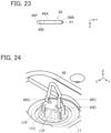
- FIGS. 22 and 23 show an inner contact 48 used in a connector according to Embodiment 4.
- This inner contact 48 is composed of a bent wire spring made of a conductive material such as metal, and includes a horizontal portion 48A extending in the Y direction across the fitting axis C and having opposite ends curved toward the -Z direction.
- a first extending portion 48C extending along the fitting axis C is joined to a +Y directional end portion of the horizontal portion 48A via a first bent portion 48B, and a first projecting portion 48D is formed at an intermediate part of the first extending portion 48C.
- a second extending portion 48E is joined to a -Y directional end portion of the horizontal portion 48A, and a third extending portion 48G is joined to a tip of the second extending portion 48E via a second bent portion 48F.
- the first projecting portion 48D projects in the +Y direction to be separated away from the second extending portion 48E.
- the second extending portion 48E is slightly inclined with respect to the fitting axis C to be separated away from the second extending portion 48C toward the -Z direction
- the third extending portion 48G is slightly inclined with respect to the fitting axis C to approach the first extending portion 48C toward the -Z direction.
- the inner contact 48 does not have any portions intersecting each other unlike the inner contacts 18, 28, 38 in Embodiments 1 to 3, and has the only one contact portion P1 and the only one pressing portion P2.
- this inner contact 48 can also be retained by the bottom insulator 17 by respectively inserting the first extending portion 48C and the third extending portion 48G into the pair of grooves 17F of the projection 17C as shown in FIG. 24 .
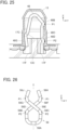
- the single contact portion P1 formed at the first bent portion 48B comes into contact with the inner surface on the +Y direction side of the recessed portion 13C of the plug contact 13 as shown in FIG. 25 , whereby the inner contact 48 is electrically connected to the plug contact 13.
- the single pressing portion P2 formed at the first projecting portion 48D faces the inner surface on the +Y direction side of the recessed portion 13C of the plug contact 13.
- both the shield layer 15D and the shield layer 15F respectively disposed on the front surface side and the rear surface side of the sheet type conductive member 15 can be electrically connected to the single plug contact 13 arranged in the region R1.
- FIGS. 26 and 27 show an inner contact 58 used in a connector according to Embodiment 5.
- This inner contact 58 has a similar shape to that of the inner contact 18 used in Embodiment 1 and shown in FIG. 12 but has a position that is vertically reversed with respect to the inner contact 18.
- the inner contact 58 includes a horizontal portion 58A disposed at a -Z directional end portion of the inner contact 58.
- the horizontal portion 58A extends in the Y direction across the fitting axis C and has opposite ends curved toward the +Z direction, and a first oblique portion 58D and a second oblique portion 58E are joined to -Y and +Y directional end portions of the horizontal portion 58A via a first bent portion 58B and a second bent portion 58C, respectively.
- the first oblique portion 58D linearly extends from the first bent portion 58B toward the +Y direction and the +Z direction
- the second oblique portion 58E linearly extends from the second bent portion 58C toward the -Y direction and the +Z direction
- these first and second oblique portions 58D and 58E extend obliquely with respect to the fitting axis C while intersecting each other.
- a first extending portion 58H and a second extending portion 58J are joined to a tip of the first oblique portion 58D and a tip of the second oblique portion 58E via a third bent portion 58F and a fourth bent portion 58G, respectively.
- the first extending portion 58H and the second extending portion 58J face each other in the Y direction across the fitting axis C and extend obliquely with respect to the fitting axis C such that the distance therebetween in the Y direction decreases toward the +Z direction, and the first extending portion 58H and the second extending portion 58J are disengaged from each other in the +Z direction.
- FIG. 28 shows a bottom insulator 57 used in the connector according to Embodiment 5.
- the bottom insulator 57 includes a projection 57C in place of the projection 17C in the bottom insulator 17 used in Embodiment 1 and shown in FIG. 4 , and otherwise has the same configuration as the bottom insulator 17.
- the bottom insulator 57 has the flat plate portion 17A provided with the four circular recessed portions 17B, and of the four recessed portions 17B, one recessed portion 17B situated on the -X direction side and -Y direction side is provided with the projection 57C projecting in the +Z direction, and the other three recessed portions 17B are separately provided with the three projections 17D projecting in the +Z direction.
- the projection 57C has a substantially regular hexagonal prism shape extending in the Z direction and is provided with a groove 57F crossing the projection 57C in the Y direction, and this groove 57F forms a retaining portion for retaining the inner contact 58.
- the inner contact 58 can be retained by the bottom insulator 57 by inserting the horizontal portion 58A, the first bent portion 58B and the second bent portion 58C into the groove 57F of the projection 57C.
- the pair of contact portions P1 of the inner contact 58 are pressed against the inner surface of the recessed portion 13C of the plug contact 13, whereby the inner contact 58 is electrically connected to the plug contact 13.
- the pair of pressing portions P2 of the inner contact 58 face the inner surface of the recessed portion 13C of the plug contact 13.
- both the shield layer 15D and the shield layer 15F respectively disposed on the front surface side and the rear surface side of the sheet type conductive member 15 can be electrically connected to the single plug contact 13 arranged in the region R1.
- the pair of contact portions P1 are respectively formed at the third bent portion 58F and the fourth bent portion 58G respectively joined to the first extending portion 58H and the second extending portion 58J disengaged from each other in the +Z direction, even when a dimension tolerance at the time of manufacturing the inner contact 58 varies, fluctuation in a contact force of the pair of contact portions P1 with respect to the inner surface of the recessed portion 13C of the plug contact 13 can be reduced.
- the inner contacts 18, 28, 38, 48, 58 used in Embodiments 1 to 5 above can be easily produced at a low cost by, for example, performing a forming process on a metal wire, without requiring a complex production apparatus.
- the inner contacts 18, 28, 38, 48, 58 capable of corresponding to the sheet type conductive members 15 can be easily obtained only by adjusting the forming process.
- the plug contact 13 arranged in the region R1 of the sheet type conductive member 15 is connected to both the shield layer 15D and the shield layer 15F respectively exposed on the front surface side and the rear surface side of the sheet type conductive member 15 in Embodiments 1 to 5 above, only the shield layer 15F exposed on the rear surface side of the sheet type conductive member 15 may be connected to the plug contact 13 arranged in the region R1, for instance.
- the sheet type conductive member 15 used in Embodiments 1 to 5 above has the multilayer structure shown in FIG. 8 , the invention is not limited thereto, and it suffices if the sheet type conductive member has a flexible conductor disposed on at least one surface side of the sheet body.
- the invention is not limited thereto, and three or more conductive layers may be connected to the single plug contact 13.
- the connector 11 according to Embodiments 1 to 5 above has the four plug contacts 13 including the contact used as a shield terminal and the contacts used as signal terminals, the invention is not limited to this number of plug contacts, and it suffices if the connector includes at least a single plug contact 13 electrically connected to a flexible conductor disposed on the front surface side or the rear surface side of the sheet body of the sheet type conductive member 15.
Landscapes
- Coupling Device And Connection With Printed Circuit (AREA)
Abstract
Description
- The present invention relates to a connector, particularly to a connector connected to a sheet type connection object having a flexible conductor exposed on at least one surface of the connection object.
- In recent years, attention has been drawn to so-called smart clothes that can obtain user's biological data such as the heart rate and the body temperature only by being worn by the user. Such smart clothes have an electrode disposed at a measurement site, and when a wearable device serving as a measurement device is electrically connected to the electrode, biological data can be transmitted to the wearable device.
- The electrode and the wearable device can be interconnected by, for instance, use of a connector connected to a flexible conductor drawn from the electrode.
- As a connector of this type, for example,
JP 2018-129244 A FIG. 32 . This connector includes ahousing 2 and abase member 3 that are separately disposed on opposite sides across aflexible substrate 1 to sandwich theflexible substrate 1. Atubular portion 4A of acontact 4 is passed through a contact through-hole 2A of thehousing 2, and aflange 4B of thecontact 4 is sandwiched between thehousing 2 and aflexible conductor 1A exposed on a surface of theflexible substrate 1. - In this state, by pushing the
base member 3 toward thehousing 2, as shown inFIG. 33 , aprojection 3A of thebase member 3 is inserted into aprojection accommodating portion 4C of thecontact 4 with theflexible substrate 1 being sandwiched therebetween, and an inner surface of theprojection accommodating portion 4C makes contact with theflexible conductor 1A with a predetermined contact force, whereby thecontact 4 is electrically connected to theflexible conductor 1A. - In addition, as shown in
FIG. 32 , thehousing 2 and thebase member 3 are fixed to each other by press-fitting ahousing fixing post 3B, which is formed to project on thebase member 3, into a post accommodatingportion 2B of thehousing 2. - When a wearable device is fitted with the connector disclosed in
JP 2018-129244 A - However, when the
flexible conductor 1A is exposed on the rear surface of theflexible substrate 1, the connector ofJP 2018-129244A contact 4, disadvantageously. - The present invention has been made to solve the foregoing problem and aims at providing a connector that enables to make an electrical connection of a contact to a flexible conductor of a connection object regardless of whether the flexible conductor is exposed on the front surface or the rear surface of the connection object.
- A connector according to the present invention comprises:
- a plug contact having a tubular shape and conductivity, the plug contact including a recessed portion extending along a fitting axis; and
- an inner contact having conductivity, the inner contact being inserted in the recessed portion and composed of a bent wire spring,
- wherein the inner contact includes a contact portion that is elastically displaceable in a direction orthogonal to the fitting axis and makes contact with the plug contact in the recessed portion, and a pressing portion that is elastically displaceable in the direction orthogonal to the fitting axis and is disposed in the recessed portion, and
- wherein part of a connection object of sheet shape having a flexible conductor exposed on at least one surface of the connection object is sandwiched between the pressing portion and an inner surface of the recessed portion in the direction orthogonal to the fitting axis, the inner surface of the recessed portion makes contact with a front surface of the connection object, and the pressing portion makes contact with a rear surface of the connection object, whereby the plug contact is electrically connected to the flexible conductor directly when the flexible conductor is exposed on the front surface of the connection object, and the plug contact is electrically connected to the flexible conductor via the inner contact when the flexible conductor is exposed on the rear surface of the connection object.
-
-
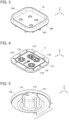
FIG. 1 is a perspective view showing a connector according toEmbodiment 1. -
FIG. 2 is an exploded perspective view of the connector according toEmbodiment 1. -
FIG. 3 is a perspective view showing a top insulator used in the connector ofEmbodiment 1. -
FIG. 4 is a perspective view showing a bottom insulator used in the connector ofEmbodiment 1. -
FIG. 5 is an enlarged view of a main part ofFIG. 4 . -
FIG. 6 is a perspective view showing a plug contact used in the connector ofEmbodiment 1. -
FIG. 7 is a cross-sectional view showing the plug contact used in the connector ofEmbodiment 1. -
FIG. 8 is a cross-sectional view showing a connection object that is connected to the connector ofEmbodiment 1. -
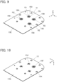
FIG. 9 is a perspective view of the connection object that is connected to the connector ofEmbodiment 1, as viewed from an obliquely upper position. -
FIG. 10 is a perspective view of the connection object that is connected to the connector ofEmbodiment 1, as viewed from an obliquely lower position. -
FIG. 11 is a perspective view showing a reinforcement sheet used in the connector ofEmbodiment 1. -
FIG. 12 is a front view showing an inner contact used in the connector ofEmbodiment 1. -
FIG. 13 is a plan view showing the inner contact used in the connector ofEmbodiment 1. -
FIG. 14 is a perspective view showing the inner contact inEmbodiment 1 retained by the bottom insulator. -
FIG. 15 is a partial cross-sectional view showing a state of an inside of the plug contact in which the inner contact in the connector ofEmbodiment 1 connected to the connection object is inserted. -
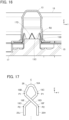
FIG. 16 is a partial cross-sectional view showing a state of an inside of the plug contact in which a projection in the connector ofEmbodiment 1 connected to the connection object is inserted. -
FIG. 17 is a front view showing an inner contact in Embodiment 2. -
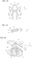
FIG. 18 is a front view showing an inner contact in Embodiment 3. -
FIG. 19 is a plan view showing the inner contact in Embodiment 3. -
FIG. 20 is a perspective view showing the inner contact inEmbodiment 3 retained by the bottom insulator. -
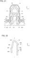
FIG. 21 is a partial cross-sectional view showing a state of an inside of the plug contact in which the inner contact inEmbodiment 3 is inserted. -
FIG. 22 is a front view showing an inner contact in Embodiment 4. -
FIG. 23 is a plan view showing the inner contact in Embodiment 4. -
FIG. 24 is a perspective view showing the inner contact inEmbodiment 4 retained by the bottom insulator. -
FIG. 25 is a partial cross-sectional view showing a state of an inside of the plug contact in which the inner contact inEmbodiment 4 is inserted. -
FIG. 26 is a front view showing an inner contact in Embodiment 5. -
FIG. 27 is a plan view showing the inner contact in Embodiment 5. -
FIG. 28 is a perspective view showing a bottom insulator used in the connector of Embodiment 5. -
FIG. 29 is an enlarged view of a main part ofFIG. 28 . -
FIG. 30 is a perspective view showing the inner contact in Embodiment 5 retained by the bottom insulator. -
FIG. 31 is a partial cross-sectional view showing a state of an inside of the plug contact in which the inner contact in Embodiment 5 is inserted. -
FIG. 32 is an exploded perspective view showing a conventional connector. -
FIG. 33 is a partial cross-sectional view showing the conventional connector. - Embodiments of the present invention are described below based on the accompanying drawings.
-
FIG. 1 shows aconnector 11 according toEmbodiment 1. Theconnector 11 is used as, for example, a garment-side connector for fitting a wearable device, and has ahousing 12 made of an insulating material. In thehousing 12, fourplug contacts 13 are retained, and areinforcement sheet 14 and a sheet typeconductive member 15 are retained by thehousing 12 while being superposed on each other. The sheet typeconductive member 15 constitutes a connection object that is connected to thecontact 11. - The four
plug contacts 13 are disposed to project perpendicularly to the sheet typeconductive member 15 in two lines parallel to each other. - For convenience, the
reinforcement sheet 14 and the sheet typeconductive member 15 are defined as extending along an XY plane, the direction in which the fourplug contacts 13 are aligned is referred to as "Y direction," and the direction in which the fourplug contacts 13 project is referred to as "+Z direction." The Z direction is a fitting direction in which theconnector 11 is fitted to a counter connector. -
FIG. 2 is an exploded perspective view of theconnector 11. Theconnector 11 includes atop insulator 16 and abottom insulator 17, and these top andbottom insulators housing 12. - The
reinforcement sheet 14 is disposed on the -Z direction side of thetop insulator 16, the fourplug contacts 13 are disposed on the -Z direction side of thereinforcement sheet 14, and the sheet typeconductive member 15 is disposed on the -Z direction side of the fourplug contacts 13. Further, a singleinner contact 18 is disposed on the -Z direction side of the sheet typeconductive member 15, and thebottom insulator 17 is disposed on the -Z direction side of theinner contact 18. Theinner contact 18 corresponds to, of the fourplug contacts 13, oneplug contact 13 that is situated on the -X direction side and the -Y direction side. - As shown in
FIG. 3 , thetop insulator 16 includes a recessedportion 16A opening in the +Z direction, and four contact through-holes 16B formed within the recessedportion 16A. The recessedportion 16A constitutes a counter connector accommodating portion in which part of a counter connector (not shown) is to be accommodated, and the four contact through-holes 16B separately correspond to the fourplug contacts 13. In addition, on a surface, facing in the -Z direction, of thetop insulator 16, a plurality ofbosses 16C are formed to project in the -Z direction. - As shown in
FIG. 4 , thebottom insulator 17 includes aflat plate portion 17A, and theflat plate portion 17A is provided with four circular recessedportions 17B opening in the +Z direction. The four recessedportions 17B separately correspond to the fourplug contacts 13. Of the four recessedportions 17B, one recessedportion 17B situated on the -X direction side and -Y direction side is provided with aprojection 17C projecting in the +Z direction, and the other three recessedportions 17B are separately provided with threeprojections 17D projecting in the +Z direction. - In addition, the
flat plate portion 17A is provided with a plurality of through-holes 17E separately corresponding to the plurality ofbosses 16C of thetop insulator 16. - As shown in
FIG. 5 , theprojection 17C formed in the recessedportion 17B situated on the -X direction side and the -Y direction side of thebottom insulator 17 has a substantially regular hexagonal prism shape extending in the Z direction. A pair ofgrooves 17F extending in the Z direction are separately formed in lateral surfaces, facing in the +Y and -Y directions, of theprojection 17C, and form a retaining portion for retaining theinner contact 18. - The
projections 17D formed in the other three recessedportions 17B have the same structure as that of theprojection 17C except that each of theprojections 17D does not have the pair ofgrooves 17F. - The four
plug contacts 13 are each made of a conductive material such as metal, and are to be connected to corresponding contacts of a counter connector (not shown) when part of the counter connector is accommodated in the recessedportion 16A of thetop insulator 16. - As shown in
FIG. 6 , theplug contact 13 has atubular portion 13A of cylindrical shape extending along a fitting axis C in the Z direction, and aflange 13B extending from a -Z directional end portion of thetubular portion 13A along an XY plane. In addition, as shown inFIG. 7 , thetubular portion 13A is provided in its interior with a recessedportion 13C opening in the -Z direction. - Of the four
plug contacts 13, oneplug contact 13 situated on the -X direction side and the -Y direction side is connected to a ground potential and used as a shield terminal, and the remaining threeplug contacts 13 are each used as a signal terminal for transmitting an electric signal. - As shown in
FIG. 8 , the sheet typeconductive member 15 includes asheet body 15A made of an insulating material and has a multilayer structure in which: asignal wiring layer 15B formed from a flexible conductor, an insulatinglayer 15C, ashield layer 15D formed from a flexible conductor, and an insulatinglayer 15E are sequentially laminated on a front surface, facing in the +Z direction, of thesheet body 15A; and ashield layer 15F formed from a flexible conductor, and an insulatinglayer 15G are sequentially laminated on a rear surface, facing in the -Z direction, of thesheet body 15A. - As shown in
FIG. 9 , fourcontact arrangement regions 15H for separately arranging the fourplug contacts 13 are laid out on a front surface, facing in the +Z direction, of the sheet typeconductive member 15. Of the fourcontact arrangement regions 15H, onecontact arrangement region 15H situated on the -X direction side and the -Y direction side forms a region R1 on which theplug contact 13 used as a shield terminal is to be arranged, and the remaining threecontact arrangement regions 15H separately form regions R2 on which theplug contacts 13 used as signal terminals are to be arranged. - In the region R1 on which the
plug contact 13 serving as a shield terminal is to be arranged, the insulatinglayer 15E is removed so that theshield layer 15D is exposed toward the +Z direction. In each of the regions R2 on which the threeplug contacts 13 serving as signal terminals are to be arranged, the insulatinglayer 15E, theshield layer 15D, and the insulatinglayer 15C are removed so that thesignal wiring layer 15B is exposed toward the +Z direction. In the other region than the regions R1 and R2, the insulatinglayer 15E is exposed. - In all the regions R1 and R2, a plurality of
cuts 15J are formed to penetrate the sheet typeconductive member 15 in the Z direction. - Since the
cuts 15J penetrate the sheet typeconductive member 15 in the Z direction, as shown inFIG. 10 , thecuts 15J can be seen also on a rear surface, facing in the -Z direction, of the sheet typeconductive member 15 at positions corresponding to the one region R1 and the three regions R2. - On the rear surface, facing in the -Z direction, of the sheet type
conductive member 15, only at the position corresponding to the region R1, the insulatinglayer 15G is removed so that theshield layer 15F is exposed, and in the other regions than the region R1, the insulatinglayer 15G is exposed. - In addition, a plurality of through-
holes 15K separately corresponding to the plurality ofbosses 16C of thetop insulator 16 are formed at the periphery of the sheet typeconductive member 15. - As shown in
FIG. 11 , thereinforcement sheet 14 is provided to reinforce a mounting object such as a garment (not shown) on which theconnector 11 is to be mounted, is made of an insulating material, and has anopening portion 14A formed in the center thereof. Further, a plurality ofcutouts 14B separately corresponding to the plurality ofbosses 16C of thetop insulator 16 are formed along the periphery of theopening portion 14A of thereinforcement sheet 14. -
FIGS. 12 and 13 show the structure of theinner contact 18. Theinner contact 18 is constituted of a bent wire spring made of a conductive material such as metal, and includes ahorizontal portion 18A extending in the Y direction across the fitting axis C and having opposite ends curved toward the -Z direction. - A
first oblique portion 18D and asecond oblique portion 18E are joined to -Y and +Y directional end portions of thehorizontal portion 18A via a firstbent portion 18B and a secondbent portion 18C, respectively. Thefirst oblique portion 18D linearly extends from the firstbent portion 18B toward the +Y direction and the -Z direction, while thesecond oblique portion 18E linearly extends from the secondbent portion 18C toward the -Y direction and the -Z direction, and these first andsecond oblique portions - Further, a first extending
portion 18H and a second extendingportion 18J are joined to a tip of thefirst oblique portion 18D and a tip of thesecond oblique portion 18E via a thirdbent portion 18F and a fourthbent portion 18G, respectively. The first extendingportion 18H and the second extendingportion 18J face each other in the Y direction across the fitting axis C and extend obliquely with respect to the fitting axis C such that the distance therebetween in the Y direction decreases toward the -Z direction. - Outer surfaces, facing in opposite directions from each other, of the first
bent portion 18B and the secondbent portion 18C form a pair of contact portions P1, and outer surfaces, facing in opposite directions from each other, of the thirdbent portion 18F and the fourthbent portion 18G form a pair of pressing portions P2. - A distance in the Y direction between the pair of contact portions P1 is set to be slightly larger than an inside diameter of the part of the recessed
portion 13C with which the pair of contact portions P1 make contact when theinner contact 18 is inserted into the recessedportion 13C of theplug contact 13. - Therefore, when the
inner contact 18 is inserted into the recessedportion 13C of theplug contact 13, the pair of contact portions P1 come into contact with an inner surface of the recessedportion 13C with predetermined contact pressure while being elastically displaced in a direction toward the fitting axis C. - In addition, a distance in the Y direction between the pair of pressing portions P2 is set to be slightly larger than a value obtained by subtracting a double of the thickness of the sheet type
conductive member 15 from the inside diameter of the part of the recessedportion 13C with which the pair of pressing portions P2 make contact when theinner contact 18 is inserted into the recessedportion 13C of theplug contact 13. - Therefore, when the
inner contact 18 is inserted into the recessedportion 13C of theplug contact 13 while pushing the sheet typeconductive member 15 thereinto, the pair of pressing portions P2 is elastically displaced in the direction toward the fitting axis C and presses the sheet typeconductive member 15 against the inner surface of the recessedportion 13C with predetermined contact pressure. - As shown in
FIG. 14 , theinner contact 18 is retained by thebottom insulator 17 by respectively inserting the first extendingportion 18H and the second extendingportion 18J into the pair ofgrooves 17F of theprojection 17C of thebottom insulator 17. - The four contact through-
holes 16B of thetop insulator 16, the fourplug contacts 13, the fourcontact arrangement regions 15H of the sheet typeconductive member 15, and the four recessedportions 17B of thebottom insulator 17 are arranged so as to align with each other in the Z direction. - The
inner contact 18 is arranged so as to align in the Z direction with, of the fourcontact arrangement regions 15H of the sheet typeconductive member 15, thecontact arrangement region 15H that forms the region R1 and is situated on the -X direction side and the -Y direction side, and with, of the four recessedportions 17B of thebottom insulator 17, the recessedportion 17B in which theprojection 17C is formed and that is situated on the -X direction side and the -Y direction side. - In addition, the
bosses 16C of thetop insulator 16, thecutouts 14B of thereinforcement sheet 14, the through-holes 15K of the sheet typeconductive member 15, and the through-holes 17E of thebottom insulator 17 are arranged so as to align with each other in the Z direction. - When the
connector 11 is assembled, first, as shown inFIG. 14 , theinner contact 18 is retained by thebottom insulator 17 by respectively inserting the first extendingportion 18H and the second extendingportion 18J of theinner contact 18 into the pair ofgrooves 17F of theprojection 17C of thebottom insulator 17. - Next, the
bosses 16C of thetop insulator 16 are separately inserted into thecutouts 14B of thereinforcement sheet 14. At this time, the four contact through-holes 16B of thetop insulator 16 are situated within theopening portion 14A of thereinforcement sheet 14. - Further, the
tubular portion 13A of each of theplug contacts 13 is inserted from the -Z direction into the corresponding one of the four contact through-holes 16B of thetop insulator 16, and thebottom insulator 17 is pressed against thetop insulator 16 in the +Z direction with the sheet typeconductive member 15 being sandwiched therebetween. - At this time, the
flange 13B of each of theplug contacts 13 is situated on the correspondingcontact arrangement region 15H of the sheet typeconductive member 15, theinner contact 18 retained on theprojection 17C of thebottom insulator 17 is inserted into the recessedportion 13C of thecorresponding plug contact 13 while pushing the region R1 of the sheet typeconductive member 15 thereinto, and the threeprojections 17D of thebottom insulator 17 are separately inserted into the recessedportions 13C of thecorresponding plug contacts 13 while pushing the regions R2 of the sheet typeconductive member 15 thereinto. - Since the plurality of
cuts 15J are formed in each of the fourcontact arrangement regions 15H of the sheet typeconductive member 15, theinner contact 18 and the threeprojections 17D are each inserted into the recessedportion 13C of theplug contact 13 while opening the plurality ofcuts 15J of the correspondingcontact arrangement region 15H. - In addition, by pressing the
bottom insulator 17 against thetop insulator 16, thebosses 16C of thetop insulator 16 sequentially penetrate thecutouts 14B of thereinforcement sheet 14, the through-holes 15K of the sheet typeconductive member 15, and the through-holes 17E of thebottom insulator 17. Subsequently, thetop insulator 16 and thebottom insulator 17 are fixed to each other through heat deformation of a tip of each of the plurality ofbosses 17C projecting on the -Z direction side of thebottom insulator 17. Thus, the assembling operation of theconnector 11 is completed. - It should be noted that the
flange 13B of each of theplug contacts 13 is sandwiched between thetop insulator 16 and thebottom insulator 17 so that theplug contacts 13 are fixed to thetop insulator 16 and thebottom insulator 17. - As shown in
FIG. 15 , in theplug contact 13 used as a shield terminal, theinner contact 18 is inserted into the recessedportion 13C of theplug contact 13 while pushing the region R1 of the sheet typeconductive member 15 thereinto. Consequently, the pair of contact portions P1 of theinner contact 18 are pressed against the inner surface of the recessedportion 13C of theplug contact 13, whereby theinner contact 18 is electrically connected to theplug contact 13. - In addition, the sheet type
conductive member 15 pushed into the recessedportion 13C of theplug contact 13 by theinner contact 18 is pressed against the inner surface of the recessedportion 13C of theplug contact 13 by the pair of pressing portions P2 of theinner contact 18. - Here, as shown in
FIGS. 9 and 10 , theshield layer 15D is exposed in the region R1 of the front surface of the sheet typeconductive member 15 in which the region R1 theplug contact 13 used as a shield terminal is to be arranged, while theshield layer 15F is exposed on the rear surface of the sheet typeconductive member 15 at the position corresponding to the region R1. - Therefore, the
shield layer 15D on the front surface of the sheet typeconductive member 15 makes contact with the inner surface, facing in the Y direction, of the recessedportion 13C of theplug contact 13 with predetermined contact pressure, while theshield layer 15F on the rear surface of the sheet typeconductive member 15 makes contact with the pressing portions P2 of theinner contact 18 with predetermined contact pressure. - Consequently, the
shield layer 15D exposed on the front surface of the sheet typeconductive member 15 is electrically connected to theplug contact 13 directly, while theshield layer 15F exposed on the rear surface of the sheet typeconductive member 15 is electrically connected to plugcontact 13 via theinner contact 18. That is, both the shield layers 15D and 15F are connected to theplug contact 13 used as a shield terminal. - At this time, since the
projection 17C of thebottom insulator 17 on which theinner contact 18 is retained has a substantially regular hexagonal prism shape extending in the Z direction as shown inFIG. 5 , the sheet typeconductive member 15 is sandwiched also between lateral surfaces of corners of the hexagonal prism and the inner surface of the recessedportion 13C of theplug contact 13. Therefore, theshield layer 15D exposed on the front surface of the sheet typeconductive member 15 not only is pressed against the inner surface of the recessedportion 13C of theplug contact 13 by the pair of pressing portions P2 of theinner contact 18, but also makes contact with the inner surface of the recessedportion 13C of theplug contact 13 with predetermined contact pressure by the lateral surfaces of the corners of theprojection 17C, and is electrically connected to theplug contact 13. - It should be noted that the
projection 17C is not limited to a substantially regular hexagonal prism shape, and may have a columnar shape, for instance. - Thus, with the
connector 11, by using theinner contact 18, both theshield layer 15D and theshield layer 15F respectively disposed on the front surface side and the rear surface side of the sheet typeconductive member 15 can be electrically connected to thesingle plug contact 13 arranged in the region R1. - On the other hand, of the four
contact arrangement regions 15H laid out on the front surface of the sheet typeconductive member 15, in the three regions R2 in which the threeplug contacts 13 used as signal terminals are to be arranged, as shown inFIG. 16 , theprojection 17D of thebottom insulator 17 is inserted into the recessedportion 13C of theplug contact 13 while pushing the region R2 of the sheet typeconductive member 15 thereinto. Here, since thesignal wiring layer 15B is exposed in the region R2 of the front surface of the sheet typeconductive member 15 as shown inFIG. 9 , the sheet typeconductive member 15 is sandwiched between a lateral surface of theprojection 17D and the inner surface of the recessedportion 13C of thecontact 13, and thesignal wiring layer 15B makes contact with the inner surface of the recessedportion 13C of theplug contact 13 with predetermined contact pressure and is electrically connected to theplug contact 13 arranged in the region R2. - It should be noted that predetermined patterning is applied to the
signal wiring layer 15B, and the threeplug contacts 13 arranged in the three regions R2 are separately connected to three wirings each formed of thesignal wiring layer 15B and insulated from one another. - As shown in
FIG. 8 , since thesignal wiring layer 15B is disposed between theshield layer 15D and theshield layer 15F while being insulated from theshield layer 15D and theshield layer 15F respectively disposed on the front surface side and the rear surface side of the sheet typeconductive member 15, a shield effect with respect to thesignal wiring layer 15B is exhibited when theplug contact 13 arranged in the region R1 and connected to theshield layer 15D and theshield layer 15F is connected to a ground potential, and it is possible to carry out highly accurate signal transmission with reduced influence of external disturbances caused by, for example, electromagnetic waves. - While the
reinforcement sheet 14 is disposed between thebottom insulator 17 and thetop insulator 16 in theconnector 11 ofEmbodiment 1, thereinforcement sheet 14 may be omitted when it is not necessary to reinforce a mounting object such as a garment to which theconnector 11 is to be attached. -
FIG. 17 shows aninner contact 28 used in a connector according toEmbodiment 2. Thisinner contact 28 includes a first extendingportion 28H and a second extendingportion 28J extending in parallel to each other along the fitting axis C in place of the first extendingportion 18H and the second extendingportion 18J extending obliquely with respect to the fitting axis C in theinner contact 18 used inEmbodiment 1 and shown inFIG. 12 , and otherwise has a similar configuration to that of theinner contact 18. - That is, the
inner contact 28 includes thehorizontal portion 18A, thefirst oblique portion 18D and thesecond oblique portion 18E joined to the -Y and +Y directional end portions of thehorizontal portion 18A via the firstbent portion 18B and the secondbent portion 18C, respectively, and the first extendingportion 28H and the second extendingportion 28J are joined to the tip of thefirst oblique portion 18D and the tip of thesecond oblique portion 18E via the thirdbent portion 18F and the fourthbent portion 18G, respectively. As with theinner contact 18, the outer surfaces, facing in opposite directions to each other, of the firstbent portion 18B and the secondbent portion 18C form the pair of contact portions P1, while the outer surfaces, facing in opposite directions to each other, of the thirdbent portion 18F and the fourthbent portion 18G form the pair of pressing portions P2. - As with the
inner contact 18 inEmbodiment 1, thisinner contact 28 can also be retained by thebottom insulator 17 by respectively inserting the first extendingportion 28H and the second extendingportion 28J into the pair ofgrooves 17F of theprojection 17C shown inFIG. 5 . - Even when the
inner contact 28 shown inFIG. 17 is used in place of theinner contact 18 in theconnector 11 according toEmbodiment 1, similarly, both theshield layer 15D and theshield layer 15F respectively disposed on the front surface side and the rear surface side of the sheet typeconductive member 15 can be electrically connected to thesingle plug contact 13 arranged in the region R1. -
FIGS. 18 and 19 show aninner contact 38 used in a connector according toEmbodiment 3. Thisinner contact 38 includes: a first extendingportion 38H and a second extendingportion 38J extending along the fitting axis C in place of the first extendingportion 18H and the second extendingportion 18J extending obliquely with respect to the fitting axis C in theinner contact 18 used inEmbodiment 1 and shown inFIG. 12 ; a first projectingportion 38K bent so as to project at an intermediate part of the first extendingportion 38H in a direction away from the second extendingportion 38J; and a second projectingportion 38L bent so as to project at an intermediate part of the second extendingportion 38J in a direction away from the first extendingportion 38H, and otherwise has a similar configuration to that of theinner contact 18. - That is, the
inner contact 38 includes thehorizontal portion 18A, thefirst oblique portion 18D and thesecond oblique portion 18E joined to the -Y and +Y directional end portions of thehorizontal portion 18A via the firstbent portion 18B and the secondbent portion 18C, respectively, and the first extendingportion 38H and the second extendingportion 38J are joined to the tip of thefirst oblique portion 18D and the tip of thesecond oblique portion 18E via the thirdbent portion 18F and the fourthbent portion 18G, respectively. Further, the first projectingportion 38K and the second projectingportion 38L are formed at the intermediate part of the first extendingportion 38H and the intermediate part of the second extendingportion 38L, respectively. - In the
inner contact 38, the outer surfaces, facing in opposite directions to each other, of the firstbent portion 18B and the secondbent portion 18C form the pair of contact portions P1, while outer surfaces, facing in opposite directions to each other, of the first projectingportion 38K and the second projectingportion 38L form the pair of pressing portions P2. - As with the
inner contact 18 inEmbodiment 1, thisinner contact 38 can also be retained by thebottom insulator 17 by respectively inserting the first extendingportion 38H and the second extendingportion 38J into the pair ofgrooves 17F of theprojection 17C as shown inFIG. 20 . - When the
inner contact 38 is inserted into the recessedportion 13C of theplug contact 13, as shown inFIG. 21 , the pair of contact portions P1 of theinner contact 38 are pressed against the inner surface of the recessedportion 13C of theplug contact 13, whereby theinner contact 38 is electrically connected to theplug contact 13. In addition, each of the pair of pressing portions P2 formed at the first projectingportion 38K and the second projectingportion 38L faces the inner surface of the recessedportion 13C of theplug contact 13. - While the sheet type
conductive member 15 is omitted inFIG. 21 , when theinner contact 38 is inserted into the recessedportion 13C of thecorresponding plug contact 13 while pushing the region R1 of the sheet typeconductive member 15 thereinto, the sheet typeconductive member 15 pushed into the recessedportion 13C is pressed against the inner surface of the recessedportion 13C of theplug contact 13 by the pair of pressing portions P2 of theinner contact 38. - Thus, even when the
inner contact 38 shown inFIGS. 18 and 19 is used in place of theinner contact 18 in theconnector 11 according toEmbodiment 1, similarly, both theshield layer 15D and theshield layer 15F respectively disposed on the front surface side and the rear surface side of the sheet typeconductive member 15 can be electrically connected to thesingle plug contact 13 arranged in the region R1. -
FIGS. 22 and23 show aninner contact 48 used in a connector according toEmbodiment 4. Thisinner contact 48 is composed of a bent wire spring made of a conductive material such as metal, and includes ahorizontal portion 48A extending in the Y direction across the fitting axis C and having opposite ends curved toward the -Z direction. - A first extending
portion 48C extending along the fitting axis C is joined to a +Y directional end portion of thehorizontal portion 48A via a firstbent portion 48B, and a first projectingportion 48D is formed at an intermediate part of the first extendingportion 48C. In addition, a second extendingportion 48E is joined to a -Y directional end portion of thehorizontal portion 48A, and a third extendingportion 48G is joined to a tip of the second extendingportion 48E via a secondbent portion 48F. - The first projecting
portion 48D projects in the +Y direction to be separated away from the second extendingportion 48E. - In addition, the second extending
portion 48E is slightly inclined with respect to the fitting axis C to be separated away from the second extendingportion 48C toward the -Z direction, while the third extendingportion 48G is slightly inclined with respect to the fitting axis C to approach the first extendingportion 48C toward the -Z direction. - An outer surface, facing in the +Y direction, of the first
bent portion 48B forms a single contact portion P1, while an outer surface, facing in the +Y direction, of the first projectingportion 48D forms a single pressing portion P2. In this manner, theinner contact 48 does not have any portions intersecting each other unlike theinner contacts Embodiments 1 to 3, and has the only one contact portion P1 and the only one pressing portion P2. - As with the
inner contact 18 inEmbodiment 1, thisinner contact 48 can also be retained by thebottom insulator 17 by respectively inserting the first extendingportion 48C and the third extendingportion 48G into the pair ofgrooves 17F of theprojection 17C as shown inFIG. 24 . - When the
inner contact 48 is inserted into the recessedportion 13C of theplug contact 13, the single contact portion P1 formed at the firstbent portion 48B comes into contact with the inner surface on the +Y direction side of the recessedportion 13C of theplug contact 13 as shown inFIG. 25 , whereby theinner contact 48 is electrically connected to theplug contact 13. In addition, the single pressing portion P2 formed at the first projectingportion 48D faces the inner surface on the +Y direction side of the recessedportion 13C of theplug contact 13. - While the sheet type
conductive member 15 is omitted inFIG. 25 , when theinner contact 48 is inserted into the recessedportion 13C of thecorresponding plug contact 13 while pushing the region R1 of the sheet typeconductive member 15 thereinto, the sheet typeconductive member 15 pushed into the recessedportion 13C is pressed against the inner surface of the recessedportion 13C of theplug contact 13 by the pressing portion P2 of theinner contact 48. - Thus, even when the
inner contact 48 shown inFIGS. 22 and23 is used in place of theinner contact 18 in theconnector 11 according toEmbodiment 1, similarly, both theshield layer 15D and theshield layer 15F respectively disposed on the front surface side and the rear surface side of the sheet typeconductive member 15 can be electrically connected to thesingle plug contact 13 arranged in the region R1. -
FIGS. 26 and27 show aninner contact 58 used in a connector according to Embodiment 5. Thisinner contact 58 has a similar shape to that of theinner contact 18 used inEmbodiment 1 and shown inFIG. 12 but has a position that is vertically reversed with respect to theinner contact 18. - That is, the
inner contact 58 includes ahorizontal portion 58A disposed at a -Z directional end portion of theinner contact 58. Thehorizontal portion 58A extends in the Y direction across the fitting axis C and has opposite ends curved toward the +Z direction, and afirst oblique portion 58D and asecond oblique portion 58E are joined to -Y and +Y directional end portions of thehorizontal portion 58A via a firstbent portion 58B and a secondbent portion 58C, respectively. Thefirst oblique portion 58D linearly extends from the firstbent portion 58B toward the +Y direction and the +Z direction, while thesecond oblique portion 58E linearly extends from the secondbent portion 58C toward the -Y direction and the +Z direction, and these first andsecond oblique portions - Further, a first extending
portion 58H and a second extendingportion 58J are joined to a tip of thefirst oblique portion 58D and a tip of thesecond oblique portion 58E via a thirdbent portion 58F and a fourthbent portion 58G, respectively. The first extendingportion 58H and the second extendingportion 58J face each other in the Y direction across the fitting axis C and extend obliquely with respect to the fitting axis C such that the distance therebetween in the Y direction decreases toward the +Z direction, and the first extendingportion 58H and the second extendingportion 58J are disengaged from each other in the +Z direction. - Outer surfaces, facing in opposite directions to each other, of the third
bent portion 58F and the fourthbent portion 58G form the pair of contact portions P1, while outer surfaces, facing in opposite directions to each other, of the firstbent portion 58B and the secondbent portion 58C form the pair of pressing portions P2. -
FIG. 28 shows abottom insulator 57 used in the connector according to Embodiment 5. Thebottom insulator 57 includes aprojection 57C in place of theprojection 17C in thebottom insulator 17 used inEmbodiment 1 and shown inFIG. 4 , and otherwise has the same configuration as thebottom insulator 17. - That is, the
bottom insulator 57 has theflat plate portion 17A provided with the four circular recessedportions 17B, and of the four recessedportions 17B, one recessedportion 17B situated on the -X direction side and -Y direction side is provided with theprojection 57C projecting in the +Z direction, and the other three recessedportions 17B are separately provided with the threeprojections 17D projecting in the +Z direction. - As shown in
FIG. 29 , theprojection 57C has a substantially regular hexagonal prism shape extending in the Z direction and is provided with agroove 57F crossing theprojection 57C in the Y direction, and thisgroove 57F forms a retaining portion for retaining theinner contact 58. - As shown in
FIG. 30 , theinner contact 58 can be retained by thebottom insulator 57 by inserting thehorizontal portion 58A, the firstbent portion 58B and the secondbent portion 58C into thegroove 57F of theprojection 57C. - When the
inner contact 58 is inserted into the recessedportion 13C of theplug contact 13, as shown inFIG. 31 , the pair of contact portions P1 of theinner contact 58 are pressed against the inner surface of the recessedportion 13C of theplug contact 13, whereby theinner contact 58 is electrically connected to theplug contact 13. In addition, the pair of pressing portions P2 of theinner contact 58 face the inner surface of the recessedportion 13C of theplug contact 13. - While the sheet type
conductive member 15 is omitted inFIG. 31 , when theinner contact 58 is inserted into the recessedportion 13C of thecorresponding plug contact 13 while pushing the region R1 of the sheet typeconductive member 15 thereinto, the sheet typeconductive member 15 pushed into the recessedportion 13C is pressed against the inner surface of the recessedportion 13C of theplug contact 13 by the pair of pressing portions P2 of theinner contact 58. - Thus, even when the
bottom insulator 57 shown inFIG. 28 and theinner contact 58 shown inFIGS. 26 and27 are used in place of thebottom insulator 17 and theinner contact 18 in theconnector 11 according toEmbodiment 1, similarly, both theshield layer 15D and theshield layer 15F respectively disposed on the front surface side and the rear surface side of the sheet typeconductive member 15 can be electrically connected to thesingle plug contact 13 arranged in the region R1. - Since in the
inner contact 58 in Embodiment 5, the pair of contact portions P1 are respectively formed at the thirdbent portion 58F and the fourthbent portion 58G respectively joined to the first extendingportion 58H and the second extendingportion 58J disengaged from each other in the +Z direction, even when a dimension tolerance at the time of manufacturing theinner contact 58 varies, fluctuation in a contact force of the pair of contact portions P1 with respect to the inner surface of the recessedportion 13C of theplug contact 13 can be reduced. - The
inner contacts Embodiments 1 to 5 above can be easily produced at a low cost by, for example, performing a forming process on a metal wire, without requiring a complex production apparatus. - Also in the case where the sheet type
conductive members 15 each serving as a connection object are different in thickness, theinner contacts conductive members 15 can be easily obtained only by adjusting the forming process. - While the
plug contact 13 arranged in the region R1 of the sheet typeconductive member 15 is connected to both theshield layer 15D and theshield layer 15F respectively exposed on the front surface side and the rear surface side of the sheet typeconductive member 15 inEmbodiments 1 to 5 above, only theshield layer 15F exposed on the rear surface side of the sheet typeconductive member 15 may be connected to theplug contact 13 arranged in the region R1, for instance. - While the sheet type
conductive member 15 used inEmbodiments 1 to 5 above has the multilayer structure shown inFIG. 8 , the invention is not limited thereto, and it suffices if the sheet type conductive member has a flexible conductor disposed on at least one surface side of the sheet body. - In addition, while the two conductive layers, i.e., the
shield layer 15D and theshield layer 15F of the sheet typeconductive member 15 are connected to thesingle plug contact 13 used as a shield terminal inEmbodiments 1 to 5 above, the invention is not limited thereto, and three or more conductive layers may be connected to thesingle plug contact 13. - In addition, while the
connector 11 according toEmbodiments 1 to 5 above has the fourplug contacts 13 including the contact used as a shield terminal and the contacts used as signal terminals, the invention is not limited to this number of plug contacts, and it suffices if the connector includes at least asingle plug contact 13 electrically connected to a flexible conductor disposed on the front surface side or the rear surface side of the sheet body of the sheet typeconductive member 15.
Claims (11)
- A connector comprising:a plug contact (13) having a tubular shape and conductivity, the plug contact including a recessed portion (13C) extending along a fitting axis (C); andan inner contact (18, 28, 38, 48, 58) having conductivity, the inner contact being inserted in the recessed portion and composed of a bent wire spring,wherein the inner contact includes a contact portion (P1) that is elastically displaceable in a direction orthogonal to the fitting axis and makes contact with the plug contact in the recessed portion, and a pressing portion (P2) that is elastically displaceable in the direction orthogonal to the fitting axis and is disposed in the recessed portion, andwherein part of a connection object (15) of sheet shape having a flexible conductor (15B, 15D, 15F) exposed on at least one surface of the connection object is sandwiched between the pressing portion and an inner surface of the recessed portion in the direction orthogonal to the fitting axis, the inner surface of the recessed portion makes contact with a front surface of the connection object, and the pressing portion makes contact with a rear surface of the connection object, whereby the plug contact is electrically connected to the flexible conductor directly when the flexible conductor is exposed on the front surface of the connection object, and the plug contact is electrically connected to the flexible conductor via the inner contact when the flexible conductor is exposed on the rear surface of the connection object.
- The connector according to claim 1, wherein the inner contact (18, 28, 38, 58) includes:a horizontal portion (18A, 58A) extending across the fitting axis;a first oblique portion (18D, 58D) and a second oblique portion (18E, 58E) joined to opposite ends of the horizontal portion via a first bent portion (18B, 58B) and a second bent portion (18C, 58C), respectively, and extending obliquely with respect to the fitting axis while intersecting each other; anda first extending portion (18H, 28H, 38H, 58H) and a second extending portion (18J, 28J, 38J, 58J) joined to a tip of the first oblique portion and a tip of the second oblique portion via a third bent portion (18F, 58F) and a fourth bent portion (18G, 58G), respectively, and extending along the fitting axis in a direction away from the horizontal direction while facing each other across the fitting axis.
- The connector according to claim 2, wherein each of the first bent portion (18B) and the second bent portion (18C) forms the contact portion (p1), and
wherein each of the third bent portion (18F) and the fourth bent portion (18G) forms the pressing portion (P2). - The connector according to claim 3, wherein the first extending portion (28H, 38H) and the second extending portion (28J, 38J) extend in parallel to each other.
- The connector according to claim 3, wherein the first extending portion (18H, 58H) and the second extending portion (18J, 58J) extend obliquely with respect to the fitting axis such that a distance between the first extending portion and the second extending portion decreases as being farther from the horizontal portion (18A, 58A).
- The connector according to claim 2, wherein the first extending portion (38H) has a first projecting portion (38K) bent so as to project in a direction away from the second extending portion,wherein the second extending portion (38J) has a second projecting portion (38L) bent so as to project in a direction away from the first extending portion,wherein each of the first bent portion (18B) and the second bent portion (18C) forms the contact portion (P1), andwherein each of the first projecting portion (38K) and the second projecting portion (38L) forms the pressing portion (P2).
- The connector according to claim 2, wherein each of the third bent portion (58F) and the fourth bent portion (58G) forms the contact portion (P1), and
wherein each of the first bent portion (58B) and the second bent portion (58C) forms the pressing portion (P2). - The connector according to claim 1, wherein the inner contact (48) includes:a horizontal portion (48A) extending across the fitting axis;a first extending portion (48C) joined to one end of the horizontal portion via a first bent portion (48B) and extending along the fitting axis;a second extending portion (48E) extending from another end of the horizontal portion along the fitting axis; anda first projecting portion (48D) bent so as to project in a direction away from the second extending portion at an intermediate part of the first extending portion.
- The connector according to claim 8, wherein the first bent portion (48B) forms the contact portion (P1), and
wherein the first projecting portion (48D) forms the pressing portion (P2). - The connector according to any one of claims 1-9, wherein the plug contact (13) has a tubular portion (13A) and a flange (13B) that is formed at one end of the tubular portion, and
wherein the recessed portion (13C) is composed of an inside of the tubular portion. - The connector according to claim 10, comprising a housing (12) having insulating properties and configured to retain the connection object (15), the plug contact (13), and the inner contact (18, 28, 38, 48, 58),
wherein the housing includes:a top insulator (16) provided with a contact through-hole (16B) that is penetrated by the tubular portion (13A) of the plug contact and is smaller than the flange (13B); anda bottom insulator (17) having a retaining portion (17F, 57F) for retaining the inner contact, andwherein the top insulator is fixed to the bottom insulator such that the tubular portion of the plug contact penetrates the contact through-hole and the connection object and the flange are sandwiched between the top insulator and the bottom insulator.
Applications Claiming Priority (1)
| Application Number | Priority Date | Filing Date | Title |
|---|---|---|---|
| JP2022124627A JP7881403B2 (en) | 2022-08-04 | 2022-08-04 | connector |
Publications (2)
| Publication Number | Publication Date |
|---|---|
| EP4318813A1 true EP4318813A1 (en) | 2024-02-07 |
| EP4318813B1 EP4318813B1 (en) | 2025-10-29 |
Family
ID=86732576
Family Applications (1)
| Application Number | Title | Priority Date | Filing Date |
|---|---|---|---|
| EP23178033.9A Active EP4318813B1 (en) | 2022-08-04 | 2023-06-07 | Connector |
Country Status (4)
| Country | Link |
|---|---|
| US (1) | US12567691B2 (en) |
| EP (1) | EP4318813B1 (en) |
| JP (1) | JP7881403B2 (en) |
| CN (1) | CN117525937A (en) |
Families Citing this family (1)
| Publication number | Priority date | Publication date | Assignee | Title |
|---|---|---|---|---|
| JP2025132682A (en) * | 2024-02-29 | 2025-09-10 | 日本航空電子工業株式会社 | connector |
Citations (3)
| Publication number | Priority date | Publication date | Assignee | Title |
|---|---|---|---|---|
| JP2018129244A (en) | 2017-02-10 | 2018-08-16 | 日本航空電子工業株式会社 | connector |
| EP3376601A1 (en) * | 2017-03-17 | 2018-09-19 | Japan Aviation Electronics Industry, Ltd. | Connector |
| JP2021061225A (en) * | 2019-10-03 | 2021-04-15 | 日本航空電子工業株式会社 | Connector and connection method |
Family Cites Families (8)
| Publication number | Priority date | Publication date | Assignee | Title |
|---|---|---|---|---|
| GB2515104B (en) * | 2013-06-14 | 2015-07-22 | Suunto Oy | A device and a method for assembling an electronic device and a flexible element for facilitating assembly of electronic components |
| EP3435490B1 (en) * | 2017-07-24 | 2019-11-20 | Japan Aviation Electronics Industry, Ltd. | Connection assisting member and circuit board assembly |
| JP6826961B2 (en) * | 2017-07-24 | 2021-02-10 | 日本航空電子工業株式会社 | Connector and wiring board assembly |
| SE542380C2 (en) * | 2018-07-16 | 2020-04-21 | Inuheat Group Ab | Electrical connector |
| JP7128686B2 (en) * | 2018-08-07 | 2022-08-31 | 日本航空電子工業株式会社 | connector |
| JP7178956B2 (en) * | 2019-05-17 | 2022-11-28 | 日本航空電子工業株式会社 | Connection method, connection structure and connection terminal assembly |
| JP7232144B2 (en) * | 2019-07-19 | 2023-03-02 | 日本航空電子工業株式会社 | connector |
| US11258189B2 (en) * | 2019-10-03 | 2022-02-22 | Japan Aviation Electronics Industry, Limited | Connector and connecting method |
-
2022
- 2022-08-04 JP JP2022124627A patent/JP7881403B2/en active Active
-
2023
- 2023-06-02 CN CN202310653596.4A patent/CN117525937A/en active Pending
- 2023-06-07 EP EP23178033.9A patent/EP4318813B1/en active Active
- 2023-07-03 US US18/217,797 patent/US12567691B2/en active Active
Patent Citations (3)
| Publication number | Priority date | Publication date | Assignee | Title |
|---|---|---|---|---|
| JP2018129244A (en) | 2017-02-10 | 2018-08-16 | 日本航空電子工業株式会社 | connector |
| EP3376601A1 (en) * | 2017-03-17 | 2018-09-19 | Japan Aviation Electronics Industry, Ltd. | Connector |
| JP2021061225A (en) * | 2019-10-03 | 2021-04-15 | 日本航空電子工業株式会社 | Connector and connection method |
Also Published As
| Publication number | Publication date |
|---|---|
| CN117525937A (en) | 2024-02-06 |
| US12567691B2 (en) | 2026-03-03 |
| US20240047913A1 (en) | 2024-02-08 |
| JP2024021641A (en) | 2024-02-16 |
| EP4318813B1 (en) | 2025-10-29 |
| JP7881403B2 (en) | 2026-06-29 |
Similar Documents
| Publication | Publication Date | Title |
|---|---|---|
| EP4346017B1 (en) | Connector | |
| EP4300713A1 (en) | Sheet type conductive member and connector | |
| US12424774B2 (en) | Connector | |
| EP4329104B1 (en) | Connector | |
| EP4507128B1 (en) | Connector and connector assembly | |
| EP4395079B1 (en) | Connector and connecting method | |
| EP4318813B1 (en) | Connector | |
| EP3799218B1 (en) | Connector | |
| EP4611180A1 (en) | Connector | |
| EP4462605B1 (en) | Connector | |
| US12537336B2 (en) | Connector | |
| JP2024033809A (en) | Connectors and connector assemblies | |
| JP2024021591A (en) | connector | |
| EP4333216A1 (en) | Connector |
Legal Events
| Date | Code | Title | Description |
|---|---|---|---|
| PUAI | Public reference made under article 153(3) epc to a published international application that has entered the european phase |
Free format text: ORIGINAL CODE: 0009012 |
|
| STAA | Information on the status of an ep patent application or granted ep patent |
Free format text: STATUS: REQUEST FOR EXAMINATION WAS MADE |
|
| 17P | Request for examination filed |
Effective date: 20230607 |
|
| AK | Designated contracting states |
Kind code of ref document: A1 Designated state(s): AL AT BE BG CH CY CZ DE DK EE ES FI FR GB GR HR HU IE IS IT LI LT LU LV MC ME MK MT NL NO PL PT RO RS SE SI SK SM TR |
|
| RBV | Designated contracting states (corrected) |
Designated state(s): AL AT BE BG CH CY CZ DE DK EE ES FI FR GB GR HR HU IE IS IT LI LT LU LV MC ME MK MT NL NO PL PT RO RS SE SI SK SM TR |
|
| STAA | Information on the status of an ep patent application or granted ep patent |
Free format text: STATUS: EXAMINATION IS IN PROGRESS |
|
| 17Q | First examination report despatched |
Effective date: 20240506 |
|
| RAP3 | Party data changed (applicant data changed or rights of an application transferred) |
Owner name: JAPAN AVIATION ELECTRONICS INDUSTRY, LIMITED |
|
| GRAP | Despatch of communication of intention to grant a patent |
Free format text: ORIGINAL CODE: EPIDOSNIGR1 |
|
| STAA | Information on the status of an ep patent application or granted ep patent |
Free format text: STATUS: GRANT OF PATENT IS INTENDED |
|
| RIC1 | Information provided on ipc code assigned before grant |
Ipc: H01R 12/59 20110101AFI20250710BHEP Ipc: H01R 12/65 20110101ALI20250710BHEP Ipc: H05K 1/18 20060101ALI20250710BHEP Ipc: H01R 12/70 20110101ALN20250710BHEP Ipc: H01R 13/33 20060101ALN20250710BHEP Ipc: H05K 1/11 20060101ALN20250710BHEP |
|
| INTG | Intention to grant announced |
Effective date: 20250722 |
|
| RIC1 | Information provided on ipc code assigned before grant |
Ipc: H01R 12/59 20110101AFI20250714BHEP Ipc: H01R 12/65 20110101ALI20250714BHEP Ipc: H05K 1/18 20060101ALI20250714BHEP Ipc: H01R 12/70 20110101ALN20250714BHEP Ipc: H01R 13/33 20060101ALN20250714BHEP Ipc: H05K 1/11 20060101ALN20250714BHEP |
|
| GRAS | Grant fee paid |
Free format text: ORIGINAL CODE: EPIDOSNIGR3 |
|
| GRAA | (expected) grant |
Free format text: ORIGINAL CODE: 0009210 |
|
| STAA | Information on the status of an ep patent application or granted ep patent |
Free format text: STATUS: THE PATENT HAS BEEN GRANTED |
|
| AK | Designated contracting states |
Kind code of ref document: B1 Designated state(s): AL AT BE BG CH CY CZ DE DK EE ES FI FR GB GR HR HU IE IS IT LI LT LU LV MC ME MK MT NL NO PL PT RO RS SE SI SK SM TR |
|
| REG | Reference to a national code |
Ref country code: CH Ref legal event code: F10 Free format text: ST27 STATUS EVENT CODE: U-0-0-F10-F00 (AS PROVIDED BY THE NATIONAL OFFICE) Effective date: 20251029 Ref country code: GB Ref legal event code: FG4D |
|
| REG | Reference to a national code |
Ref country code: DE Ref legal event code: R096 Ref document number: 602023007928 Country of ref document: DE |
|
| REG | Reference to a national code |
Ref country code: IE Ref legal event code: FG4D |
|
| REG | Reference to a national code |
Ref country code: NL Ref legal event code: MP Effective date: 20251029 |
|
| PG25 | Lapsed in a contracting state [announced via postgrant information from national office to epo] |
Ref country code: ES Free format text: LAPSE BECAUSE OF FAILURE TO SUBMIT A TRANSLATION OF THE DESCRIPTION OR TO PAY THE FEE WITHIN THE PRESCRIBED TIME-LIMIT Effective date: 20251029 |
|
| REG | Reference to a national code |
Ref country code: LT Ref legal event code: MG9D |
|
| PG25 | Lapsed in a contracting state [announced via postgrant information from national office to epo] |
Ref country code: NO Free format text: LAPSE BECAUSE OF FAILURE TO SUBMIT A TRANSLATION OF THE DESCRIPTION OR TO PAY THE FEE WITHIN THE PRESCRIBED TIME-LIMIT Effective date: 20260129 |
|
| PG25 | Lapsed in a contracting state [announced via postgrant information from national office to epo] |
Ref country code: HR Free format text: LAPSE BECAUSE OF FAILURE TO SUBMIT A TRANSLATION OF THE DESCRIPTION OR TO PAY THE FEE WITHIN THE PRESCRIBED TIME-LIMIT Effective date: 20251029 Ref country code: FI Free format text: LAPSE BECAUSE OF FAILURE TO SUBMIT A TRANSLATION OF THE DESCRIPTION OR TO PAY THE FEE WITHIN THE PRESCRIBED TIME-LIMIT Effective date: 20251029 Ref country code: AT Free format text: LAPSE BECAUSE OF FAILURE TO SUBMIT A TRANSLATION OF THE DESCRIPTION OR TO PAY THE FEE WITHIN THE PRESCRIBED TIME-LIMIT Effective date: 20251029 |
|
| REG | Reference to a national code |
Ref country code: AT Ref legal event code: MK05 Ref document number: 1852761 Country of ref document: AT Kind code of ref document: T Effective date: 20251029 |
|
| PG25 | Lapsed in a contracting state [announced via postgrant information from national office to epo] |
Ref country code: NL Free format text: LAPSE BECAUSE OF FAILURE TO SUBMIT A TRANSLATION OF THE DESCRIPTION OR TO PAY THE FEE WITHIN THE PRESCRIBED TIME-LIMIT Effective date: 20251029 |
|
| PG25 | Lapsed in a contracting state [announced via postgrant information from national office to epo] |
Ref country code: RS Free format text: LAPSE BECAUSE OF FAILURE TO SUBMIT A TRANSLATION OF THE DESCRIPTION OR TO PAY THE FEE WITHIN THE PRESCRIBED TIME-LIMIT Effective date: 20260129 |
|
| PG25 | Lapsed in a contracting state [announced via postgrant information from national office to epo] |
Ref country code: IS Free format text: LAPSE BECAUSE OF FAILURE TO SUBMIT A TRANSLATION OF THE DESCRIPTION OR TO PAY THE FEE WITHIN THE PRESCRIBED TIME-LIMIT Effective date: 20260228 |
|
| PG25 | Lapsed in a contracting state [announced via postgrant information from national office to epo] |
Ref country code: PT Free format text: LAPSE BECAUSE OF FAILURE TO SUBMIT A TRANSLATION OF THE DESCRIPTION OR TO PAY THE FEE WITHIN THE PRESCRIBED TIME-LIMIT Effective date: 20260302 |
|
| PG25 | Lapsed in a contracting state [announced via postgrant information from national office to epo] |
Ref country code: PL Free format text: LAPSE BECAUSE OF FAILURE TO SUBMIT A TRANSLATION OF THE DESCRIPTION OR TO PAY THE FEE WITHIN THE PRESCRIBED TIME-LIMIT Effective date: 20251029 |
|
| PG25 | Lapsed in a contracting state [announced via postgrant information from national office to epo] |
Ref country code: LV Free format text: LAPSE BECAUSE OF FAILURE TO SUBMIT A TRANSLATION OF THE DESCRIPTION OR TO PAY THE FEE WITHIN THE PRESCRIBED TIME-LIMIT Effective date: 20251029 |
|
| PG25 | Lapsed in a contracting state [announced via postgrant information from national office to epo] |
Ref country code: BG Free format text: LAPSE BECAUSE OF FAILURE TO SUBMIT A TRANSLATION OF THE DESCRIPTION OR TO PAY THE FEE WITHIN THE PRESCRIBED TIME-LIMIT Effective date: 20251029 |
|
| PG25 | Lapsed in a contracting state [announced via postgrant information from national office to epo] |
Ref country code: LT Free format text: LAPSE BECAUSE OF FAILURE TO SUBMIT A TRANSLATION OF THE DESCRIPTION OR TO PAY THE FEE WITHIN THE PRESCRIBED TIME-LIMIT Effective date: 20251029 |
|
| PG25 | Lapsed in a contracting state [announced via postgrant information from national office to epo] |
Ref country code: SM Free format text: LAPSE BECAUSE OF FAILURE TO SUBMIT A TRANSLATION OF THE DESCRIPTION OR TO PAY THE FEE WITHIN THE PRESCRIBED TIME-LIMIT Effective date: 20251029 |
|
| PG25 | Lapsed in a contracting state [announced via postgrant information from national office to epo] |
Ref country code: DK Free format text: LAPSE BECAUSE OF FAILURE TO SUBMIT A TRANSLATION OF THE DESCRIPTION OR TO PAY THE FEE WITHIN THE PRESCRIBED TIME-LIMIT Effective date: 20251029 |
|
| PG25 | Lapsed in a contracting state [announced via postgrant information from national office to epo] |
Ref country code: IT Free format text: LAPSE BECAUSE OF FAILURE TO SUBMIT A TRANSLATION OF THE DESCRIPTION OR TO PAY THE FEE WITHIN THE PRESCRIBED TIME-LIMIT Effective date: 20251029 |
|
| PGFP | Annual fee paid to national office [announced via postgrant information from national office to epo] |
Ref country code: DE Payment date: 20260430 Year of fee payment: 4 |
|
| PG25 | Lapsed in a contracting state [announced via postgrant information from national office to epo] |
Ref country code: EE Free format text: LAPSE BECAUSE OF FAILURE TO SUBMIT A TRANSLATION OF THE DESCRIPTION OR TO PAY THE FEE WITHIN THE PRESCRIBED TIME-LIMIT Effective date: 20251029 |
|
| PG25 | Lapsed in a contracting state [announced via postgrant information from national office to epo] |
Ref country code: CZ Free format text: LAPSE BECAUSE OF FAILURE TO SUBMIT A TRANSLATION OF THE DESCRIPTION OR TO PAY THE FEE WITHIN THE PRESCRIBED TIME-LIMIT Effective date: 20251029 |
|
| PGFP | Annual fee paid to national office [announced via postgrant information from national office to epo] |
Ref country code: FR Payment date: 20260511 Year of fee payment: 4 |
|
| PG25 | Lapsed in a contracting state [announced via postgrant information from national office to epo] |
Ref country code: SK Free format text: LAPSE BECAUSE OF FAILURE TO SUBMIT A TRANSLATION OF THE DESCRIPTION OR TO PAY THE FEE WITHIN THE PRESCRIBED TIME-LIMIT Effective date: 20251029 |
|
| PG25 | Lapsed in a contracting state [announced via postgrant information from national office to epo] |
Ref country code: SE Free format text: LAPSE BECAUSE OF FAILURE TO SUBMIT A TRANSLATION OF THE DESCRIPTION OR TO PAY THE FEE WITHIN THE PRESCRIBED TIME-LIMIT Effective date: 20251029 |