EP4318787A1 - Pole, battery and electronic device - Google Patents
Pole, battery and electronic device Download PDFInfo
- Publication number
- EP4318787A1 EP4318787A1 EP21932295.5A EP21932295A EP4318787A1 EP 4318787 A1 EP4318787 A1 EP 4318787A1 EP 21932295 A EP21932295 A EP 21932295A EP 4318787 A1 EP4318787 A1 EP 4318787A1
- Authority
- EP
- European Patent Office
- Prior art keywords
- pole
- housing
- sealing
- connecting member
- substrate
- Prior art date
- Legal status (The legal status is an assumption and is not a legal conclusion. Google has not performed a legal analysis and makes no representation as to the accuracy of the status listed.)
- Pending
Links
- 238000007789 sealing Methods 0.000 claims abstract description 122
- 239000000758 substrate Substances 0.000 claims abstract description 37
- 230000007423 decrease Effects 0.000 claims description 4
- 238000010586 diagram Methods 0.000 description 9
- 230000000694 effects Effects 0.000 description 4
- 230000007547 defect Effects 0.000 description 3
- 238000009413 insulation Methods 0.000 description 3
- 229920000459 Nitrile rubber Polymers 0.000 description 2
- 238000005452 bending Methods 0.000 description 2
- 239000003792 electrolyte Substances 0.000 description 2
- 229920002943 EPDM rubber Polymers 0.000 description 1
- 244000043261 Hevea brasiliensis Species 0.000 description 1
- 229920000800 acrylic rubber Polymers 0.000 description 1
- 229920005549 butyl rubber Polymers 0.000 description 1
- 238000005516 engineering process Methods 0.000 description 1
- 229920001973 fluoroelastomer Polymers 0.000 description 1
- 239000000463 material Substances 0.000 description 1
- 239000002184 metal Substances 0.000 description 1
- 239000007769 metal material Substances 0.000 description 1
- 229920003052 natural elastomer Polymers 0.000 description 1
- 229920001194 natural rubber Polymers 0.000 description 1
- 229920001084 poly(chloroprene) Polymers 0.000 description 1
- 229920000058 polyacrylate Polymers 0.000 description 1
- 229920003225 polyurethane elastomer Polymers 0.000 description 1
- 238000004826 seaming Methods 0.000 description 1
- 229920002379 silicone rubber Polymers 0.000 description 1
- 239000004945 silicone rubber Substances 0.000 description 1
Images



Classifications
-
- H—ELECTRICITY
- H01—ELECTRIC ELEMENTS
- H01M—PROCESSES OR MEANS, e.g. BATTERIES, FOR THE DIRECT CONVERSION OF CHEMICAL ENERGY INTO ELECTRICAL ENERGY
- H01M50/00—Constructional details or processes of manufacture of the non-active parts of electrochemical cells other than fuel cells, e.g. hybrid cells
- H01M50/50—Current conducting connections for cells or batteries
- H01M50/543—Terminals
- H01M50/564—Terminals characterised by their manufacturing process
- H01M50/567—Terminals characterised by their manufacturing process by fixing means, e.g. screws, rivets or bolts
-
- H—ELECTRICITY
- H01—ELECTRIC ELEMENTS
- H01M—PROCESSES OR MEANS, e.g. BATTERIES, FOR THE DIRECT CONVERSION OF CHEMICAL ENERGY INTO ELECTRICAL ENERGY
- H01M50/00—Constructional details or processes of manufacture of the non-active parts of electrochemical cells other than fuel cells, e.g. hybrid cells
- H01M50/10—Primary casings; Jackets or wrappings
- H01M50/183—Sealing members
- H01M50/184—Sealing members characterised by their shape or structure
-
- H—ELECTRICITY
- H01—ELECTRIC ELEMENTS
- H01M—PROCESSES OR MEANS, e.g. BATTERIES, FOR THE DIRECT CONVERSION OF CHEMICAL ENERGY INTO ELECTRICAL ENERGY
- H01M50/00—Constructional details or processes of manufacture of the non-active parts of electrochemical cells other than fuel cells, e.g. hybrid cells
- H01M50/10—Primary casings; Jackets or wrappings
- H01M50/172—Arrangements of electric connectors penetrating the casing
- H01M50/174—Arrangements of electric connectors penetrating the casing adapted for the shape of the cells
-
- H—ELECTRICITY
- H01—ELECTRIC ELEMENTS
- H01M—PROCESSES OR MEANS, e.g. BATTERIES, FOR THE DIRECT CONVERSION OF CHEMICAL ENERGY INTO ELECTRICAL ENERGY
- H01M50/00—Constructional details or processes of manufacture of the non-active parts of electrochemical cells other than fuel cells, e.g. hybrid cells
- H01M50/10—Primary casings; Jackets or wrappings
- H01M50/147—Lids or covers
- H01M50/148—Lids or covers characterised by their shape
- H01M50/152—Lids or covers characterised by their shape for cells having curved cross-section, e.g. round or elliptic
-
- H—ELECTRICITY
- H01—ELECTRIC ELEMENTS
- H01M—PROCESSES OR MEANS, e.g. BATTERIES, FOR THE DIRECT CONVERSION OF CHEMICAL ENERGY INTO ELECTRICAL ENERGY
- H01M50/00—Constructional details or processes of manufacture of the non-active parts of electrochemical cells other than fuel cells, e.g. hybrid cells
- H01M50/10—Primary casings; Jackets or wrappings
- H01M50/172—Arrangements of electric connectors penetrating the casing
-
- H—ELECTRICITY
- H01—ELECTRIC ELEMENTS
- H01M—PROCESSES OR MEANS, e.g. BATTERIES, FOR THE DIRECT CONVERSION OF CHEMICAL ENERGY INTO ELECTRICAL ENERGY
- H01M50/00—Constructional details or processes of manufacture of the non-active parts of electrochemical cells other than fuel cells, e.g. hybrid cells
- H01M50/10—Primary casings; Jackets or wrappings
- H01M50/183—Sealing members
- H01M50/186—Sealing members characterised by the disposition of the sealing members
-
- H—ELECTRICITY
- H01—ELECTRIC ELEMENTS
- H01M—PROCESSES OR MEANS, e.g. BATTERIES, FOR THE DIRECT CONVERSION OF CHEMICAL ENERGY INTO ELECTRICAL ENERGY
- H01M50/00—Constructional details or processes of manufacture of the non-active parts of electrochemical cells other than fuel cells, e.g. hybrid cells
- H01M50/50—Current conducting connections for cells or batteries
- H01M50/543—Terminals
- H01M50/552—Terminals characterised by their shape
-
- H—ELECTRICITY
- H01—ELECTRIC ELEMENTS
- H01M—PROCESSES OR MEANS, e.g. BATTERIES, FOR THE DIRECT CONVERSION OF CHEMICAL ENERGY INTO ELECTRICAL ENERGY
- H01M50/00—Constructional details or processes of manufacture of the non-active parts of electrochemical cells other than fuel cells, e.g. hybrid cells
- H01M50/50—Current conducting connections for cells or batteries
- H01M50/543—Terminals
- H01M50/552—Terminals characterised by their shape
- H01M50/559—Terminals adapted for cells having curved cross-section, e.g. round, elliptic or button cells
-
- Y—GENERAL TAGGING OF NEW TECHNOLOGICAL DEVELOPMENTS; GENERAL TAGGING OF CROSS-SECTIONAL TECHNOLOGIES SPANNING OVER SEVERAL SECTIONS OF THE IPC; TECHNICAL SUBJECTS COVERED BY FORMER USPC CROSS-REFERENCE ART COLLECTIONS [XRACs] AND DIGESTS
- Y02—TECHNOLOGIES OR APPLICATIONS FOR MITIGATION OR ADAPTATION AGAINST CLIMATE CHANGE
- Y02E—REDUCTION OF GREENHOUSE GAS [GHG] EMISSIONS, RELATED TO ENERGY GENERATION, TRANSMISSION OR DISTRIBUTION
- Y02E60/00—Enabling technologies; Technologies with a potential or indirect contribution to GHG emissions mitigation
- Y02E60/10—Energy storage using batteries
Definitions
- This application relates to the field of electric vehicle battery technologies and particularly, to a pole, a battery, and an electronic device.
- An embodiment of this application provides a pole including a substrate and a lead-out portion disposed on the substrate.
- the lead-out portion includes a first portion, a second portion, and a mounting hole.
- the second portion is connected to an end of the first portion away from the substrate.
- the mounting hole is connected to the first portion and the second portion, where an opening of the mounting hole is located in the second portion. In a direction parallel to the substrate, minimum cross-sectional area of the first portion is greater than maximum cross-sectional area of the second portion.
- the pole has the first portion and the second portion of different cross-sectional areas disposed on the lead-out portion so that the second portion can be more easily riveted and bent against the first portion during riveting, thereby avoiding gasket warping caused by pressing during pole riveting and improving the safety and reliability of batteries.
- cross-sectional area of the second portion in the direction parallel to the substrate decreases in a direction leaving the first portion.
- the cross-sectional area of the second portion being smaller than the cross-sectional area of the first portion makes it easier to bend and rivet the second portion against the first portion.
- the first portion is a columnar structure
- the second portion is a columnar structure
- outer diameter of the first portion is greater than outer diameter of the second portion
- the lead-out portion can provide a positioning and support function during riveting of the second portion.
- An embodiment of this application further provides a battery including a housing, a cover, a sealing member, a connecting member, a cell, and a pole formed through compressive deformation of the foregoing pole.
- the housing has a rivet hole.
- the cover is connected to the housing to form a cavity together with the housing.
- the substrate is located within the cavity, the first portion is inserted into the rivet hole, and the second portion is bent away from the mounting hole.
- the sealing member is fitted on the pole and located between the housing and the pole.
- the connecting member is disposed between the second portion and the sealing member.
- the cell is disposed within the cavity and electrically connected to the pole.
- the pole of the battery has the first portion and the second portion of different cross-sectional areas disposed on the lead-out portion so that the second portion can be more easily riveted and bent against the first portion during riveting. Therefore, this reduces the acting force on the connecting member during riveting, avoids gasket warping, and ensures that the sealing member not only allows the battery to be insulatedly connected to the housing but also fills and seals a gap between the pole and the housing.
- the structure is simple and reliable. Therefore, the safety and reliability of the riveted battery can be improved.
- two ends of the connecting member are fitted against the second portion and the sealing member respectively.
- the second portion compresses the sealing member by pressing against the connecting member, to compress the sealing member so that the sealing member has the insulation and sealing function.
- an end of the connecting member near the mounting hole abuts against the second portion.
- an abutment between the connecting member and the second portion includes a slope.
- the slope allows a bent corner of the second portion not to press against the connecting member, thereby further preventing the connecting member from warping.
- the sealing member includes a first sealing segment, a second sealing segment, and a third sealing segment.
- the first sealing segment has two ends fitted against the substrate and an inner wall of the housing respectively.
- the second sealing segment is connected to the first sealing segment, and the second sealing segment has two ends fitted against the first portion and the inner wall of the rivet hole respectively.
- the third sealing segment is connected to an end of the second sealing segment away from the first sealing segment, and the third sealing segment has two ends fitted against the connecting member and an outer wall of the housing respectively.
- the sealing member can ensure that the pole is not electrically connected to the housing and fills and seals a gap between the pole and the rivet hole.
- At least any two of the first sealing segment, the second sealing segment, and the third sealing segment are integrally formed.
- the integrally formed sealing member can avoid electrical connection between the connecting member and the housing and electrical connection between the pole and the housing that are caused by the connecting member pressing the third sealing segment outward, while such electrical connection causes a short circuit of the battery.
- an end of the sealing member near the second portion has a slope.
- the slope at the end of the sealing member makes it easy for the connecting member to press the sealing member outward to deform the sealing member, thereby avoiding stacking of the sealing member during riveting.
- a part of the sealing member fitted against an inner wall of the housing has a protruding portion.
- the protruding portion can further ensure the sealing reliability between the sealing member and the inner wall of the housing.
- the cell further includes a positive electrode tab and a negative electrode tab, where one of the positive electrode tab and the negative electrode tab is electrically connected to the housing, and the other one of the positive electrode tab and the negative electrode tab is electrically connected to the pole.
- the positive electrode tab and the negative electrode tab connect the cell, the housing, and the pole together, allowing the cell to supply power to an external device.
- An embodiment of this application further provides an electronic device including a device housing and the foregoing battery, where the battery is mounted inside the device housing.
- the pole of the electronic device has the first portion and the second portion of different cross-sectional areas disposed on the lead-out portion so that the second portion can be more easily riveted and bent against the first portion during riveting. Therefore, this reduces the acting force on the connecting member during riveting, avoids gasket warping, and ensures that the sealing member not only allows the pole to be insulatedly connected to the housing but also fills and seals a gap between the pole and the housing.
- the structure is simple and reliable. Therefore, the safety and reliability of the riveted battery can be improved.
- battery 100 housing 1 cover 2 cell 3 positive electrode tab 31 negative electrode tab 32 pole 4 substrate 41 substrate surface 411 lead-out portion 42 first portion 421 second portion 422 first mounting hole 423 connecting portion 424 sealing member 5 base plate 51 extension portion 52 second mounting hole 53 first sealing segment 54 second sealing segment 55 third sealing segment 56 protruding portion 57 connecting member 6
- a component when deemed as being “connected to” another component, it may be directly connected to the another component, or there may be a component disposed in between.
- a component when deemed as being “disposed” on another component, it may be directly disposed on the another component, or there may be a component disposed in between.
- Embodiments of this application provide a pole, a battery, and an electronic device.
- the battery includes a housing, a cover, a sealing member, a connecting member, a cell, and a pole.
- the electronic device includes a device housing and a battery.
- the pole includes a substrate and a lead-out portion disposed on the substrate, where the lead-out portion includes a first portion, a second portion, and a mounting hole.
- the second portion is connected to an end of the first portion away from the substrate.
- the mounting hole is connected to the first portion and the second portion, where an opening of the mounting hole is located in the second portion. In a direction parallel to the substrate, minimum cross-sectional area of the first portion is greater than maximum cross-sectional area of the second portion.
- the pole has the first portion and the second portion of different cross-sectional areas disposed on the lead-out portion so that the second portion can be more easily riveted and bent against the first portion during riveting. Therefore, this reduces the acting force on the connecting member during riveting, and avoids warping of the connecting member and thus further prevents the connecting member from generating, during warping of the connecting member, an acting force which pulls the sealing member away from the pole, so that the sealing member not only allows the pole to be insulatedly connected to the housing but also fills and seals a gap between the pole and the housing.
- the structure is simple and reliable. Therefore, the safety and reliability of the riveted battery can be improved.
- An embodiment of this application provides an electronic device.
- the electronic device includes a device housing and a battery.
- the battery is mounted inside the device housing and supplies electrical energy to the electronic device.
- the battery 100 includes a housing 1, a cover 2, a cell 3, a sealing member 5, a connecting member 6, and a pole 4.
- the cover 2 is disposed at an opening of the housing 1.
- the cover 2 and the housing 1 form a cavity.
- the cover 2 may be welded or adhered at the opening of the housing 1.
- the cell 3 is disposed inside the cavity and includes a positive electrode plate, a negative electrode plate, a positive electrode tab 31, a negative electrode tab 32.
- the positive electrode tab 31 is connected to the positive electrode plate, and the negative electrode tab 32 is connected to the negative electrode plate.
- the pole 4 may be disposed on a side wall of the housing 1 or may be disposed on the end cover. Further description will be made below with an example of the pole 4 being disposed on the side wall of the housing 1.
- the side wall of the housing 1 is provided with a rivet hole, and the pole 4 is disposed in the rivet hole and riveted to the side wall of the housing 1.
- a part of the pole 4 is located inside the cavity of the housing 1, and a part of the pole 4 is located outside the housing 1.
- the part of the pole 4 located inside the cavity is configured to be electrically connected to the cell 3, and the part of the pole 4 located outside the housing 1 is configured to be connected to an electronic device.
- One of the positive electrode tab 31 and the negative electrode tab 32 is electrically connected to the housing 1, and the other one of the positive electrode tab 31 and the negative electrode tab 32 is electrically connected to the part of the pole 4 located inside the cavity. This ensures that the positive electrode tab 31 and the negative electrode tab 32 connect the pole 4 and the housing 1 to the positive electrode plate and the negative electrode plate inside the cell 3, allowing the cell 3 to transport electrical energy generated to the outside.
- the pole 4 is insulatedly connected to the housing 1 through the sealing member 5.
- the pole 4 includes a substrate 41 and a lead-out portion 42 disposed on the substrate 41.
- the substrate 41 has a substrate surface 411, and the lead-out portion 42 is disposed on the substrate surface 411.
- the lead-out portion 42 has a central axis, the central axis has an included angle with the substrate surface 411, and the included angle may be 90°.
- the lead-out portion 42 includes a first portion 421, a second portion 422, and a first mounting hole 423.
- the second portion 422 is connected to the first portion 421, and the second portion 422 is disposed at an end of the first portion 421 away from the substrate 41.
- the first mounting hole 423 is connected to the first portion 421 and the second portion 422, and an opening of the first mounting hole 423 is located in the second portion 422.
- length of the first mounting hole 423 is not greater than a sum of thicknesses of the lead-out portion 42 and the substrate 41, that is, the first mounting hole 423 does not run through the pole 4.
- a central axis of the first mounting hole 423 may overlap with the central axis of the lead-out portion 42.
- the substrate 41 When the pole 4 is not yet riveted into the rivet hole, the substrate 41 is located inside the housing 1, and the second portion 422 extends outside the housing 1.
- a rivet of a riveting device may be used for the connection of the first mounting hole 423 to allow for folding of the second portion 422, so as to rivet the pole 4 to the side wall of the housing 1.
- the housing 1 is generally made of metal material.
- the sealing member 5 needs to be fitted on the pole 4 so that the pole 4 is insulatedly connected to the housing 1.
- the sealing member 5 When the pole 4 fitted with the sealing member 5 is disposed in the rivet hole, a rivet is connected to the first mounting hole 423, to make the second portion 422 circumferential fold towards a direction leaving the first mounting hole 423 until the sealing member 5 tightly abuts against the side wall of the housing 1. At this time, the sealing member 5 not only allows the pole 4 to be insulatedly connected to the side wall of the housing 1, but also fills a gap between the pole 4 and the rivet hole to prevent electrolyte in the cavity from flowing out.
- the sealing member 5 can be driven to deform with the folding of the lead-out portion 42 during riveting operation, to form an "H"-shaped riveting structure, thereby ensuring the insulation and sealing effect of the sealing member 5.
- the connecting member 6 is a ring-shaped structure with a central hole, and inner diameter of the central hole corresponds to outer diameter of the lead-out portion 42, allowing the connecting member 6 to be fitted on the lead-out portion 42.
- the connecting member 6 is fitted on the second portion 422 and disposed between the second portion 422 bent and the sealing member 5, to apply planar pressure to the sealing member 5 so as to prevent damage or micro-crack defects of the sealing member 5, thereby ensuring the insulation and sealing effect of the sealing member 5.
- a connecting portion 424 is disposed between the second portion 422 and the first portion 421. During riveting operation, the connecting portion 424 can restrain and support the connecting member 6 to prevent the connecting member 6 from warping.
- an abutment between the connecting member 6 and the second portion 422 is provided with a slope.
- the slope can prevent a bent corner of the second portion 422 from pressing against the connecting member 6.
- the connecting member 6 may be a metal gasket.
- the sealing member 5 may be an insulating sealing ring, and the material of the sealing ring may be any one of silicone rubber, nitrile rubber, hydrogenated nitrile rubber, fluororubber, ethylene propylene diene monomer rubber, neoprene rubber, butyl rubber, acrylic rubber, natural rubber, or polyurethane rubber.
- the first portion 421 may be columnar.
- the second portion 422 may also be columnar.
- both the first portion 421 and the second portion 422 are cylindrical structures.
- the connecting portion 424 may form a stepped structure.
- inner diameter of the second portion 422 is made equal to inner diameter of the first portion 421 (the first mounting hole 423 is a structure of equal-diameter), and outer diameter of the second portion 422 is made smaller than outer diameter of the first portion 421; or outer diameter of the second portion 422 is made equal to outer diameter of the first portion 421, and inner diameter of the second portion 422 is made greater than outer diameter of the first portion 421 (the first mounting hole 423 is a structure of variable diameter).
- the connecting portion 424 is located at the periphery of the lead-out portion 42.
- the connecting portion 424 can restrain and support the connecting member 6 during riveting, further ensuring that the connecting member 6 does not warp.
- the second portion 422 may also be a tapered structure. That is, in a case that the inner diameter of the second portion 422 is equal to the inner diameter of the first portion 421, the outer diameter of the second portion 422 forms a taper structure, and the cross-sectional area of the second portion 422 decreases in a direction leaving the first portion 421. In a case that the outer diameter of the second portion 422 is equal to the outer diameter of the first portion 421, the inner diameter of the second portion 422 forms a tapered structure, and the cross-sectional area of the second portion 422 decreases in a direction leaving the first portion 421. A joint between the tapered surface of the second portion 422 and the first portion 421 is the connecting portion 424.
- the second portion 422 With the cross-sectional area of the second portion 422 smaller than the cross-sectional area of the first portion 421, not only the second portion 422 can be more easily riveted and bent against the first portion 421, thereby reducing the acting force exerted on the connecting member 6 during riveting and preventing the connecting member 6 from warping, but also the thickness of the riveting end can be effectively reduced, thereby increasing the energy density of the cell 3.
- the sealing member 5 may be a "T"-shaped structure with a through-hole.
- the sealing member 5 includes a base plate 51, an extension portion 52, and a second mounting hole 53.
- the extension portion 52 is disposed on the base plate 51, and the second mounting hole 53 runs through the base plate 51 and the extension portion 52.
- Inner diameter of the second mounting hole 53 corresponds to the outer diameter of the lead-out portion 42, allowing the second mounting hole 53 to be slightly fitted on the lead-out portion 42.
- the connecting member 6 is fitted on the lead-out portion 42 and abuts against an end of the extension portion 52 away from the base plate 51.
- the second portion 422 can act on the connecting member 6 so that the connecting member 6 moves in a direction approaching the first portion 421.
- the connecting member 6 acts on the extension portion 52 of the sealing member 5 and causes the extension portion 52 to fold with the first portion 421 until the connecting portion 424 stops the connecting member 6.
- the sealing member 5 is pressed and deformed into an "H" shape.
- the sealing member 5 of "H" shape is divided into three sequentially connected parts: a first sealing segment 54, a second sealing segment 55, and a third sealing segment 56, two opposite surfaces of the first sealing segment 54 are tightly fitted against the substrate surface 411 and the inner wall of the housing 1 respectively, two opposite surfaces of the second sealing segment 55 are tightly fitted against the outer surface of the first portion 421 and the inner wall of the rivet hole respectively, and two opposite surfaces of the third sealing segment 56 are tightly fitted against the connecting member 6 and an outer wall of the housing 1 respectively.
- the sealing member 5 of "H” shape allows the first sealing segment 54, the second sealing segment 55, and the third sealing segment 56 to be integrally formed.
- the third sealing segment 56 as an integral portion prevents the connecting member 6 from pressing the third sealing segment 56 outward when the connecting member 6 is subjected to the acting force of the second portion 422, while such pressing causes electrical connection between the connecting member 6 and the housing 1, which in turn causes a short circuit of the battery.
- the first sealing segment 54, the second sealing segment 55, and the third sealing segment 56 not only allow the pole 4 to be insulatedly connected to the housing 1, but also effectively fill and seal a gap between the pole 4 and the rivet hole to prevent electrolyte in the cavity from flowing out.
- an end of the extension portion 52 away from the base plate 51 may have a slope to some extent, with the inclined portion extending in a direction leaving the second mounting hole 53.
- a ring-shaped protruding portion 57 may be disposed on a side of the base plate 51 disposed with the extension portion 52.
- the slope is disposed on the end of the seaming member close to the second portion 422 to prevent the sealing member 5 from stacking in deformation.
- the protruding portion 57 is disposed on the base plate 51 of the sealing member 5 to further guarantee the sealing strength between the sealing member 5 and the inner wall of the housing 1.
- the structure is simple and reliable. Therefore, the safety and reliability of the riveted battery 100 can be improved.
Landscapes
- Chemical & Material Sciences (AREA)
- Chemical Kinetics & Catalysis (AREA)
- Electrochemistry (AREA)
- General Chemical & Material Sciences (AREA)
- Engineering & Computer Science (AREA)
- Manufacturing & Machinery (AREA)
- Connection Of Batteries Or Terminals (AREA)
- Sealing Battery Cases Or Jackets (AREA)
Abstract
Description
- This application relates to the field of electric vehicle battery technologies and particularly, to a pole, a battery, and an electronic device.
- In the prior art, when a pole is riveted, a gasket needs to be disposed between a bent part and a sealing ring of the pole. However, the pole cannot support the gasket, and therefore, it is easy for the gasket to deform and warp under pressure during riveting. Under the acting force of the gasket, the sealing ring is subjected to damage or micro-crack defects, causing a short circuit inside batteries and affecting the safety and reliability of batteries.
- In view of the foregoing situation, it is necessary to provide a pole, a battery, and an electronic device to avoid gasket warping caused by pressing during pole riveting while such warping affects the sealing effect of sealing rings.
- An embodiment of this application provides a pole including a substrate and a lead-out portion disposed on the substrate. The lead-out portion includes a first portion, a second portion, and a mounting hole. The second portion is connected to an end of the first portion away from the substrate. The mounting hole is connected to the first portion and the second portion, where an opening of the mounting hole is located in the second portion. In a direction parallel to the substrate, minimum cross-sectional area of the first portion is greater than maximum cross-sectional area of the second portion.
- The pole has the first portion and the second portion of different cross-sectional areas disposed on the lead-out portion so that the second portion can be more easily riveted and bent against the first portion during riveting, thereby avoiding gasket warping caused by pressing during pole riveting and improving the safety and reliability of batteries.
- In some embodiments of this application, cross-sectional area of the second portion in the direction parallel to the substrate decreases in a direction leaving the first portion.
- The cross-sectional area of the second portion being smaller than the cross-sectional area of the first portion makes it easier to bend and rivet the second portion against the first portion.
- In some embodiments of this application, the first portion is a columnar structure, the second portion is a columnar structure, and outer diameter of the first portion is greater than outer diameter of the second portion.
- With a stepped outer contour, the lead-out portion can provide a positioning and support function during riveting of the second portion.
- An embodiment of this application further provides a battery including a housing, a cover, a sealing member, a connecting member, a cell, and a pole formed through compressive deformation of the foregoing pole. The housing has a rivet hole. The cover is connected to the housing to form a cavity together with the housing. The substrate is located within the cavity, the first portion is inserted into the rivet hole, and the second portion is bent away from the mounting hole. The sealing member is fitted on the pole and located between the housing and the pole. The connecting member is disposed between the second portion and the sealing member. The cell is disposed within the cavity and electrically connected to the pole.
- The pole of the battery has the first portion and the second portion of different cross-sectional areas disposed on the lead-out portion so that the second portion can be more easily riveted and bent against the first portion during riveting. Therefore, this reduces the acting force on the connecting member during riveting, avoids gasket warping, and ensures that the sealing member not only allows the battery to be insulatedly connected to the housing but also fills and seals a gap between the pole and the housing. The structure is simple and reliable. Therefore, the safety and reliability of the riveted battery can be improved.
- In some embodiments of this application, two ends of the connecting member are fitted against the second portion and the sealing member respectively.
- The second portion compresses the sealing member by pressing against the connecting member, to compress the sealing member so that the sealing member has the insulation and sealing function.
- In some embodiments of this application, an end of the connecting member near the mounting hole abuts against the second portion.
- In a case of the connecting member pressing the sealing member, damage to the sealing member can be avoided, where the damage is caused when the sealing member is pressed into a gap between an end of the connecting member and the second portion.
- In some embodiments of this application, an abutment between the connecting member and the second portion includes a slope.
- The slope allows a bent corner of the second portion not to press against the connecting member, thereby further preventing the connecting member from warping.
- In some embodiments of this application, the sealing member includes a first sealing segment, a second sealing segment, and a third sealing segment. The first sealing segment has two ends fitted against the substrate and an inner wall of the housing respectively. The second sealing segment is connected to the first sealing segment, and the second sealing segment has two ends fitted against the first portion and the inner wall of the rivet hole respectively. The third sealing segment is connected to an end of the second sealing segment away from the first sealing segment, and the third sealing segment has two ends fitted against the connecting member and an outer wall of the housing respectively.
- The sealing member can ensure that the pole is not electrically connected to the housing and fills and seals a gap between the pole and the rivet hole.
- In some embodiments of this application, at least any two of the first sealing segment, the second sealing segment, and the third sealing segment are integrally formed.
- The integrally formed sealing member can avoid electrical connection between the connecting member and the housing and electrical connection between the pole and the housing that are caused by the connecting member pressing the third sealing segment outward, while such electrical connection causes a short circuit of the battery.
- In some embodiments of this application, an end of the sealing member near the second portion has a slope.
- The slope at the end of the sealing member makes it easy for the connecting member to press the sealing member outward to deform the sealing member, thereby avoiding stacking of the sealing member during riveting.
- In some embodiments of this application, a part of the sealing member fitted against an inner wall of the housing has a protruding portion.
- The protruding portion can further ensure the sealing reliability between the sealing member and the inner wall of the housing.
- In some embodiments of this application, the cell further includes a positive electrode tab and a negative electrode tab, where one of the positive electrode tab and the negative electrode tab is electrically connected to the housing, and the other one of the positive electrode tab and the negative electrode tab is electrically connected to the pole.
- The positive electrode tab and the negative electrode tab connect the cell, the housing, and the pole together, allowing the cell to supply power to an external device.
- An embodiment of this application further provides an electronic device including a device housing and the foregoing battery, where the battery is mounted inside the device housing.
- The pole of the electronic device has the first portion and the second portion of different cross-sectional areas disposed on the lead-out portion so that the second portion can be more easily riveted and bent against the first portion during riveting. Therefore, this reduces the acting force on the connecting member during riveting, avoids gasket warping, and ensures that the sealing member not only allows the pole to be insulatedly connected to the housing but also fills and seals a gap between the pole and the housing. The structure is simple and reliable. Therefore, the safety and reliability of the riveted battery can be improved.
-
-
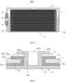
FIG. 1 is a schematic structural diagram of a battery according to an embodiment of this application. -
FIG. 2 is a partial cross-sectional view of a battery according to an embodiment of this application. -
FIG. 3 is an enlarged view of a pole according to an embodiment of this application. -
FIG. 4 is a schematic structural diagram of a pole according to an embodiment of this application. -
FIG. 5 is a schematic structural diagram of a pole according to another embodiment of this application. -
FIG. 6 is a schematic structural diagram of a pole according to another embodiment of this application. -
FIG. 7 is a schematic structural diagram of a pole according to another embodiment of this application. -
FIG. 8 is a schematic structural diagram of a sealing member according to an embodiment of this application. -
FIG. 9 is a schematic structural diagram of a to-be-riveted pole part according to an embodiment of this application. -
FIG. 10 is a schematic structural diagram of a sealing member according to another embodiment of this application. -
FIG. 11 is a schematic structural diagram of a sealing member according to another embodiment of this application. -
battery 100 housing 1 cover 2 cell 3 positive electrode tab 31 negative electrode tab 32 pole 4 substrate 41 substrate surface 411 lead-out portion 42 first portion 421 second portion 422 first mounting hole 423 connecting portion 424 sealing member 5 base plate 51 extension portion 52 second mounting hole 53 first sealing segment 54 second sealing segment 55 third sealing segment 56 protruding portion 57 connecting member 6 - This application will be further described with reference to the accompanying drawings in the following specific embodiments.
- The following describes the technical solutions in the embodiments of this application with reference to the accompanying drawings in the embodiments of this application. Apparently, the described embodiments are only some rather than all of the embodiments of this application.
- It should be noted that when a component is deemed as being "connected to" another component, it may be directly connected to the another component, or there may be a component disposed in between. When a component is deemed as being "disposed" on another component, it may be directly disposed on the another component, or there may be a component disposed in between.
- Unless otherwise defined, all technical and scientific terms used herein shall have the same meanings as commonly understood by those skilled in the art to which this application pertains. The terms used herein in the specification of this application are for description of specific embodiments only without any intention to limit this application.
- Embodiments of this application provide a pole, a battery, and an electronic device. The battery includes a housing, a cover, a sealing member, a connecting member, a cell, and a pole. The electronic device includes a device housing and a battery. The pole includes a substrate and a lead-out portion disposed on the substrate, where the lead-out portion includes a first portion, a second portion, and a mounting hole. The second portion is connected to an end of the first portion away from the substrate. The mounting hole is connected to the first portion and the second portion, where an opening of the mounting hole is located in the second portion. In a direction parallel to the substrate, minimum cross-sectional area of the first portion is greater than maximum cross-sectional area of the second portion.
- The pole has the first portion and the second portion of different cross-sectional areas disposed on the lead-out portion so that the second portion can be more easily riveted and bent against the first portion during riveting. Therefore, this reduces the acting force on the connecting member during riveting, and avoids warping of the connecting member and thus further prevents the connecting member from generating, during warping of the connecting member, an acting force which pulls the sealing member away from the pole, so that the sealing member not only allows the pole to be insulatedly connected to the housing but also fills and seals a gap between the pole and the housing. The structure is simple and reliable. Therefore, the safety and reliability of the riveted battery can be improved.
- The following further describes the embodiments of this application with reference to the accompanying drawings.
- An embodiment of this application provides an electronic device. The electronic device includes a device housing and a battery. The battery is mounted inside the device housing and supplies electrical energy to the electronic device.
- As shown in
FIGs. 1 and2 , thebattery 100 includes ahousing 1, acover 2, acell 3, a sealingmember 5, a connectingmember 6, and apole 4. - The
cover 2 is disposed at an opening of thehousing 1. Thecover 2 and thehousing 1 form a cavity. - The
cover 2 may be welded or adhered at the opening of thehousing 1. - The
cell 3 is disposed inside the cavity and includes a positive electrode plate, a negative electrode plate, apositive electrode tab 31, anegative electrode tab 32. Thepositive electrode tab 31 is connected to the positive electrode plate, and thenegative electrode tab 32 is connected to the negative electrode plate. - The
pole 4 may be disposed on a side wall of thehousing 1 or may be disposed on the end cover. Further description will be made below with an example of thepole 4 being disposed on the side wall of thehousing 1. - The side wall of the
housing 1 is provided with a rivet hole, and thepole 4 is disposed in the rivet hole and riveted to the side wall of thehousing 1. In addition, a part of thepole 4 is located inside the cavity of thehousing 1, and a part of thepole 4 is located outside thehousing 1. The part of thepole 4 located inside the cavity is configured to be electrically connected to thecell 3, and the part of thepole 4 located outside thehousing 1 is configured to be connected to an electronic device. - One of the
positive electrode tab 31 and thenegative electrode tab 32 is electrically connected to thehousing 1, and the other one of thepositive electrode tab 31 and thenegative electrode tab 32 is electrically connected to the part of thepole 4 located inside the cavity. This ensures that thepositive electrode tab 31 and thenegative electrode tab 32 connect thepole 4 and thehousing 1 to the positive electrode plate and the negative electrode plate inside thecell 3, allowing thecell 3 to transport electrical energy generated to the outside. - Further description will be made below with an example of the
positive electrode tab 31 being connected to thepole 4 and thenegative electrode tab 32 being connected to thehousing 1. - As shown in
FIGs. 3 and4 , after riveted in the rivet hole, thepole 4 is insulatedly connected to thehousing 1 through the sealingmember 5. - The
pole 4 includes asubstrate 41 and a lead-outportion 42 disposed on thesubstrate 41. Thesubstrate 41 has asubstrate surface 411, and the lead-outportion 42 is disposed on thesubstrate surface 411. - The lead-out
portion 42 has a central axis, the central axis has an included angle with thesubstrate surface 411, and the included angle may be 90°. - The lead-out
portion 42 includes afirst portion 421, asecond portion 422, and a first mountinghole 423. - The
second portion 422 is connected to thefirst portion 421, and thesecond portion 422 is disposed at an end of thefirst portion 421 away from thesubstrate 41. - The
first mounting hole 423 is connected to thefirst portion 421 and thesecond portion 422, and an opening of the first mountinghole 423 is located in thesecond portion 422. - In a central axis direction of the first mounting
hole 423, length of the first mountinghole 423 is not greater than a sum of thicknesses of the lead-outportion 42 and thesubstrate 41, that is, the first mountinghole 423 does not run through thepole 4. - A central axis of the first mounting
hole 423 may overlap with the central axis of the lead-outportion 42. - When the
pole 4 is not yet riveted into the rivet hole, thesubstrate 41 is located inside thehousing 1, and thesecond portion 422 extends outside thehousing 1. A rivet of a riveting device may be used for the connection of the first mountinghole 423 to allow for folding of thesecond portion 422, so as to rivet thepole 4 to the side wall of thehousing 1. - Further description will be made below with an example of implementing edge folding of the
second portion 422 through a rivet. - The
housing 1 is generally made of metal material. In order to prevent thepole 4 from coming into contact with thehousing 1 to cause a short circuit of thebattery 100, the sealingmember 5 needs to be fitted on thepole 4 so that thepole 4 is insulatedly connected to thehousing 1. - When the
pole 4 fitted with the sealingmember 5 is disposed in the rivet hole, a rivet is connected to the first mountinghole 423, to make thesecond portion 422 circumferential fold towards a direction leaving the first mountinghole 423 until the sealingmember 5 tightly abuts against the side wall of thehousing 1. At this time, the sealingmember 5 not only allows thepole 4 to be insulatedly connected to the side wall of thehousing 1, but also fills a gap between thepole 4 and the rivet hole to prevent electrolyte in the cavity from flowing out. - During riveting operation, it is difficult to control the bending amount of the
second portion 422. As a result, it is highly likely that the sealing ring is over-compressed duo to excessive riveting, causing damage or micro-crack defects, or has no sealing effect due to inadequate riveting. Therefore, in this embodiment of this application, with the connectingmember 6 fitted on the lead-outportion 42, the sealingmember 5 can be driven to deform with the folding of the lead-outportion 42 during riveting operation, to form an "H"-shaped riveting structure, thereby ensuring the insulation and sealing effect of the sealingmember 5. - The connecting
member 6 is a ring-shaped structure with a central hole, and inner diameter of the central hole corresponds to outer diameter of the lead-outportion 42, allowing the connectingmember 6 to be fitted on the lead-outportion 42. - Furthermore, the connecting
member 6 is fitted on thesecond portion 422 and disposed between thesecond portion 422 bent and the sealingmember 5, to apply planar pressure to the sealingmember 5 so as to prevent damage or micro-crack defects of the sealingmember 5, thereby ensuring the insulation and sealing effect of the sealingmember 5. - Moreover, in order to effectively control the bending amount of the
second portion 422, a connectingportion 424 is disposed between thesecond portion 422 and thefirst portion 421. During riveting operation, the connectingportion 424 can restrain and support the connectingmember 6 to prevent the connectingmember 6 from warping. - To further prevent the connecting
member 6 from warping, an abutment between the connectingmember 6 and thesecond portion 422 is provided with a slope. The slope can prevent a bent corner of thesecond portion 422 from pressing against the connectingmember 6. - The connecting
member 6 may be a metal gasket. - The sealing
member 5 may be an insulating sealing ring, and the material of the sealing ring may be any one of silicone rubber, nitrile rubber, hydrogenated nitrile rubber, fluororubber, ethylene propylene diene monomer rubber, neoprene rubber, butyl rubber, acrylic rubber, natural rubber, or polyurethane rubber. - As shown in
FIGs. 3 ,4 ,5 ,6, and 7 , thefirst portion 421 may be columnar. - In a case that the
first portion 421 is columnar, thesecond portion 422 may also be columnar. In this case, since the first mountinghole 423 is connected to thefirst portion 421 and thesecond portion 422, both thefirst portion 421 and thesecond portion 422 are cylindrical structures. In order to make cross-sectional area of thesecond portion 422 smaller than cross-sectional area of thefirst portion 421, thefirst portion 421, thesecond portion 422, and the connectingportion 424 may form a stepped structure. That is, inner diameter of thesecond portion 422 is made equal to inner diameter of the first portion 421 (the first mountinghole 423 is a structure of equal-diameter), and outer diameter of thesecond portion 422 is made smaller than outer diameter of thefirst portion 421; or outer diameter of thesecond portion 422 is made equal to outer diameter of thefirst portion 421, and inner diameter of thesecond portion 422 is made greater than outer diameter of the first portion 421 (the first mountinghole 423 is a structure of variable diameter). - In a case that the inner diameter of the
second portion 422 is equal to the inner diameter of thefirst portion 421 and that the outer diameter of thesecond portion 422 is smaller than the outer diameter of thefirst portion 421, the connectingportion 424 is located at the periphery of the lead-outportion 42. The connectingportion 424 can restrain and support the connectingmember 6 during riveting, further ensuring that the connectingmember 6 does not warp. - In a case that the
first portion 421 is columnar, thesecond portion 422 may also be a tapered structure. That is, in a case that the inner diameter of thesecond portion 422 is equal to the inner diameter of thefirst portion 421, the outer diameter of thesecond portion 422 forms a taper structure, and the cross-sectional area of thesecond portion 422 decreases in a direction leaving thefirst portion 421. In a case that the outer diameter of thesecond portion 422 is equal to the outer diameter of thefirst portion 421, the inner diameter of thesecond portion 422 forms a tapered structure, and the cross-sectional area of thesecond portion 422 decreases in a direction leaving thefirst portion 421. A joint between the tapered surface of thesecond portion 422 and thefirst portion 421 is the connectingportion 424. - With the cross-sectional area of the
second portion 422 smaller than the cross-sectional area of thefirst portion 421, not only thesecond portion 422 can be more easily riveted and bent against thefirst portion 421, thereby reducing the acting force exerted on the connectingmember 6 during riveting and preventing the connectingmember 6 from warping, but also the thickness of the riveting end can be effectively reduced, thereby increasing the energy density of thecell 3. - As shown in
FIGs. 3 ,8 ,9 ,10, and 11 , in order to tightly fit the sealingmember 5 on thepole 4, the sealingmember 5 may be a "T"-shaped structure with a through-hole. - The sealing
member 5 includes abase plate 51, anextension portion 52, and a second mountinghole 53. Theextension portion 52 is disposed on thebase plate 51, and the second mountinghole 53 runs through thebase plate 51 and theextension portion 52. Inner diameter of the second mountinghole 53 corresponds to the outer diameter of the lead-outportion 42, allowing the second mountinghole 53 to be slightly fitted on the lead-outportion 42. - In a case that the sealing
member 5 is fitted on thepole 4 at a predetermined position, a surface of thebase plate 51 away from theextension portion 52 is fitted against thesubstrate surface 411, and an inner wall of the second mountinghole 53 is fitted against the lead-outportion 42. - In a case that the
pole 4 fitted with the sealingmember 5 is disposed in the rivet hole at a predetermined position but has not been riveted yet, a surface of thebase plate 51 facing away from thesubstrate 41 is fitted against the inner wall of thehousing 1, and a surface of theextension portion 52 facing away from the lead-outportion 42 abuts against the side wall of the rivet hole. This ensures that thesubstrate 41 and thefirst portion 421 do not come into direct contact with thehousing 1, thereby preventing a short circuit of thebattery 100. - The connecting
member 6 is fitted on the lead-outportion 42 and abuts against an end of theextension portion 52 away from thebase plate 51. When thesecond portion 422 is bent outward under the action of the rivet, thesecond portion 422 can act on the connectingmember 6 so that the connectingmember 6 moves in a direction approaching thefirst portion 421. The connectingmember 6 acts on theextension portion 52 of the sealingmember 5 and causes theextension portion 52 to fold with thefirst portion 421 until the connectingportion 424 stops the connectingmember 6. At this time, under the action of the connectingmember 6, the sealingmember 5 is pressed and deformed into an "H" shape. - If the sealing
member 5 of "H" shape is divided into three sequentially connected parts: afirst sealing segment 54, asecond sealing segment 55, and a third sealing segment 56, two opposite surfaces of thefirst sealing segment 54 are tightly fitted against thesubstrate surface 411 and the inner wall of thehousing 1 respectively, two opposite surfaces of thesecond sealing segment 55 are tightly fitted against the outer surface of thefirst portion 421 and the inner wall of the rivet hole respectively, and two opposite surfaces of the third sealing segment 56 are tightly fitted against the connectingmember 6 and an outer wall of thehousing 1 respectively. The sealingmember 5 of "H" shape allows thefirst sealing segment 54, thesecond sealing segment 55, and the third sealing segment 56 to be integrally formed. Compared with the third sealing segment 56 as a separate component, the third sealing segment 56 as an integral portion prevents the connectingmember 6 from pressing the third sealing segment 56 outward when the connectingmember 6 is subjected to the acting force of thesecond portion 422, while such pressing causes electrical connection between the connectingmember 6 and thehousing 1, which in turn causes a short circuit of the battery. - The
first sealing segment 54, thesecond sealing segment 55, and the third sealing segment 56 not only allow thepole 4 to be insulatedly connected to thehousing 1, but also effectively fill and seal a gap between thepole 4 and the rivet hole to prevent electrolyte in the cavity from flowing out. - In order to effectively fold the
extension portion 52 when the connectingmember 6 presses against the sealingmember 5, so as to prevent theextension portion 52 from stacking, an end of theextension portion 52 away from thebase plate 51 may have a slope to some extent, with the inclined portion extending in a direction leaving the second mountinghole 53. - In the riveted state, to further ensure the sealing strength between the
base plate 51 and the inner wall of thehousing 1, a ring-shaped protrudingportion 57 may be disposed on a side of thebase plate 51 disposed with theextension portion 52. - To sum up, in the
pole 4 described above, with thefirst portion 421 and thesecond portion 422 with different cross-sectional areas disposed on the lead-outportion 42, not only thesecond portion 422 can be more easily riveted and bent against thefirst portion 421, thereby reducing the acting force exerted on the connectingmember 6 during riveting and preventing the connectingmember 6 from warping, but also the thickness of the riveting end can be effectively reduced, thereby increasing the energy density of thecell 3. Riveting the "T"-shapedsealing member 5 into an "H" shape can effectively prevents electrical connection between the connectingmember 6 and thehousing 1 caused by the connectingmember 6 pressing the sealingmember 5 outward. The slope is disposed on the end of the seaming member close to thesecond portion 422 to prevent the sealingmember 5 from stacking in deformation. The protrudingportion 57 is disposed on thebase plate 51 of the sealingmember 5 to further guarantee the sealing strength between the sealingmember 5 and the inner wall of thehousing 1. The structure is simple and reliable. Therefore, the safety and reliability of the rivetedbattery 100 can be improved. - In addition, persons skilled in the art can also make other changes within the spirit of this application. Certainly, these changes made according to the spirit of this application shall fall within the scope of this application.
Claims (12)
- A pole comprising a substrate and a lead-out portion disposed on the substrate, wherein the lead-out portion comprises:a first portion;a second portion connected to an end of the first portion away from the substrate; anda mounting hole connected to the first portion and the second portion, wherein an opening of the mounting hole is located in the second portion; whereinin a direction parallel to the substrate, minimum cross-sectional area of the first portion is greater than maximum cross-sectional area of the second portion.
- The pole according to claim 1, wherein cross-sectional area of the second portion in the direction parallel to the substrate decreases in a direction leaving the first portion.
- The pole according to claim 1, wherein the first portion is a columnar structure, the second portion is a columnar structure, and outer diameter of the first portion is greater than outer diameter of the second portion.
- A battery comprising:a housing having a rivet hole;a cover connected to the housing to form a cavity together with the housing;a pole, wherein the pole is formed through compressive deformation of the pole according to any one of claims 1 to 3, the substrate is located within the cavity, the first portion is inserted into the rivet hole, and the second portion is bent away from the mounting hole;a sealing member fitted on the pole and located between the housing and the pole;a connecting member disposed between the second portion and the sealing member; anda cell disposed within the cavity and electrically connected to the pole.
- The battery according to claim 4, wherein two ends of the connecting member are fitted against the second portion and the sealing member respectively.
- The battery according to claim 4, wherein an end of the connecting member near the mounting hole abuts against the second portion.
- The battery according to claim 6, wherein an abutment between the connecting member and the second portion comprises a slope.
- The battery according to claim 4, wherein the sealing member comprises:a first sealing segment having two ends fitted against the substrate and an inner wall of the housing respectively;a second sealing segment connected to the first sealing segment, wherein two ends of the second sealing segment are fitted against the first portion and an inner wall of the rivet hole respectively; anda third sealing segment connected to an end of the second sealing segment away from the first sealing segment, wherein two ends of the third sealing segment are fitted against the connecting member and an outer wall of the housing respectively.
- The battery according to claim 8, wherein at least any two of the first sealing segment, the second sealing segment, and the third sealing segment are integrally formed.
- The battery according to claim 4, wherein an end of the sealing member near the second portion has a slope.
- The battery according to claim 4, wherein a part of the sealing member fitted against an inner wall of the housing has a protruding portion.
- An electronic device comprising a device housing, and further comprising the battery according to any one of claims 4 to 11, wherein the battery is mounted inside the device housing.
Applications Claiming Priority (1)
| Application Number | Priority Date | Filing Date | Title |
|---|---|---|---|
| PCT/CN2021/083424 WO2022198676A1 (en) | 2021-03-26 | 2021-03-26 | Pole, battery and electronic device |
Publications (2)
| Publication Number | Publication Date |
|---|---|
| EP4318787A1 true EP4318787A1 (en) | 2024-02-07 |
| EP4318787A4 EP4318787A4 (en) | 2024-08-21 |
Family
ID=80489976
Family Applications (1)
| Application Number | Title | Priority Date | Filing Date |
|---|---|---|---|
| EP21932295.5A Pending EP4318787A4 (en) | 2021-03-26 | 2021-03-26 | POLE, BATTERY AND ELECTRONIC DEVICE |
Country Status (4)
| Country | Link |
|---|---|
| US (1) | US20240014525A1 (en) |
| EP (1) | EP4318787A4 (en) |
| CN (1) | CN114175371B (en) |
| WO (1) | WO2022198676A1 (en) |
Cited By (1)
| Publication number | Priority date | Publication date | Assignee | Title |
|---|---|---|---|---|
| EP4510321A1 (en) * | 2023-07-25 | 2025-02-19 | Eve Energy Co., Ltd. | Explosion-proof battery |
Families Citing this family (14)
| Publication number | Priority date | Publication date | Assignee | Title |
|---|---|---|---|---|
| CN114759319B (en) * | 2022-06-15 | 2022-09-20 | 宁德新能源科技有限公司 | Electrochemical device and electronic apparatus |
| CN218242180U (en) * | 2022-07-20 | 2023-01-06 | 欣旺达电动汽车电池有限公司 | Pole, single battery and battery pack |
| CN115832638B (en) * | 2022-08-16 | 2025-03-18 | 宁德新能源科技有限公司 | Electrochemical devices and electronic devices |
| CN115566331B (en) * | 2022-09-08 | 2024-01-26 | 宁夏宝丰昱能科技有限公司 | Cover plate assembly, assembly method and battery |
| CN116073088A (en) * | 2023-02-28 | 2023-05-05 | 安徽得壹能源科技有限公司 | Lithium battery anode pressure riveting front structure, lithium battery anode, lithium battery and method |
| CN116111242A (en) * | 2023-02-28 | 2023-05-12 | 安徽得壹能源科技有限公司 | Lithium battery steel shell assembly and lithium battery comprising same |
| CN116487786A (en) * | 2023-05-31 | 2023-07-25 | 湖北亿纬动力有限公司 | Top cover assembly and battery |
| CN116581493B (en) * | 2023-07-12 | 2023-12-15 | 深圳海辰储能控制技术有限公司 | Top cap subassembly and have its battery cell |
| CN221447420U (en) * | 2023-09-12 | 2024-07-30 | 宁德时代新能源科技股份有限公司 | Battery monomer, battery and electric equipment |
| CN120826827A (en) * | 2023-09-28 | 2025-10-21 | 宁德时代新能源科技股份有限公司 | Battery cells, batteries, and electrical equipment |
| CN117374491B (en) * | 2023-12-07 | 2024-02-20 | 蜂巢能源科技股份有限公司 | Battery and electric equipment |
| CN222051932U (en) * | 2023-12-27 | 2024-11-22 | 深圳市科达利实业股份有限公司 | Cylindrical battery |
| CN222146502U (en) * | 2024-04-01 | 2024-12-10 | 比亚迪股份有限公司 | Conductive column, cover plate assembly, battery device and electric equipment |
| CN119181925B (en) * | 2024-11-25 | 2025-03-11 | 常州武进中瑞电子科技股份有限公司 | Battery structure and assembly method thereof |
Family Cites Families (8)
| Publication number | Priority date | Publication date | Assignee | Title |
|---|---|---|---|---|
| CN201584437U (en) * | 2009-11-17 | 2010-09-15 | 凯迈嘉华(洛阳)新能源有限公司 | Electrode leading-out structure and accumulating electric component using the same |
| KR102441922B1 (en) * | 2015-05-14 | 2022-09-08 | 삼성에스디아이 주식회사 | Rechargeable battery |
| JP6292243B2 (en) * | 2016-02-16 | 2018-03-14 | トヨタ自動車株式会社 | Sealed battery |
| US20180183018A1 (en) * | 2016-12-26 | 2018-06-28 | Gs Yuasa International Ltd. | Energy storage device |
| CN106684269A (en) * | 2017-01-19 | 2017-05-17 | 佛山市康荣精细陶瓷有限公司 | Cover plate structure for lithium battery and manufacturing method thereof |
| JP7346988B2 (en) * | 2019-08-05 | 2023-09-20 | 株式会社村田製作所 | battery |
| CN111430588B (en) * | 2020-03-03 | 2023-08-22 | 珠海冠宇电池股份有限公司 | Shell assembly of button cell, button cell and electronic product |
| CN112290133A (en) * | 2020-11-18 | 2021-01-29 | 江西百思利新能源科技股份有限公司 | Secondary battery top cover and assembling method thereof, and secondary battery |
-
2021
- 2021-03-26 EP EP21932295.5A patent/EP4318787A4/en active Pending
- 2021-03-26 WO PCT/CN2021/083424 patent/WO2022198676A1/en not_active Ceased
- 2021-03-26 CN CN202180004645.0A patent/CN114175371B/en active Active
-
2023
- 2023-09-25 US US18/372,170 patent/US20240014525A1/en active Pending
Cited By (1)
| Publication number | Priority date | Publication date | Assignee | Title |
|---|---|---|---|---|
| EP4510321A1 (en) * | 2023-07-25 | 2025-02-19 | Eve Energy Co., Ltd. | Explosion-proof battery |
Also Published As
| Publication number | Publication date |
|---|---|
| US20240014525A1 (en) | 2024-01-11 |
| CN114175371B (en) | 2023-05-02 |
| EP4318787A4 (en) | 2024-08-21 |
| CN114175371A (en) | 2022-03-11 |
| WO2022198676A1 (en) | 2022-09-29 |
Similar Documents
| Publication | Publication Date | Title |
|---|---|---|
| US20240014525A1 (en) | Pole, battery, and electronic device | |
| CN102544396B (en) | Electrical storage device | |
| KR101586597B1 (en) | Sealing arrangement of a battery filling port using a rivet | |
| JP5040698B2 (en) | Capacitors | |
| CN103329303B (en) | Charge storage element | |
| EP1705732A1 (en) | Lithium secondary battery | |
| CN217589179U (en) | Top cover assembly and battery | |
| EP2485291B1 (en) | Electric storage device | |
| KR100458437B1 (en) | Sealed battery | |
| KR102599683B1 (en) | Charging terminal sealed structure using rivets | |
| US11245135B2 (en) | Secondary battery with insulating tapes | |
| US9692022B2 (en) | Rechargeable battery | |
| JP5837468B2 (en) | Sealed battery | |
| CN106486614B (en) | rechargeable battery | |
| JP4590911B2 (en) | battery | |
| US20240162539A1 (en) | Sealing plate and power storage device using same | |
| US20250183434A1 (en) | Housing, electrochemical device and manufacturing method thereof, and electronic device | |
| JP5105241B2 (en) | Electrolytic capacitor | |
| CN209626266U (en) | A battery cover | |
| JP6704826B2 (en) | Electronic component manufacturing method and electronic component | |
| JP6456802B2 (en) | Current interrupt device and power storage device using the same | |
| EP3477731A1 (en) | Rechargeable battery | |
| JP6780620B2 (en) | Sealed battery | |
| CN218274983U (en) | A cylindrical battery cell and electrical equipment | |
| CN215644690U (en) | Battery cover plate assembly and battery |
Legal Events
| Date | Code | Title | Description |
|---|---|---|---|
| STAA | Information on the status of an ep patent application or granted ep patent |
Free format text: STATUS: THE INTERNATIONAL PUBLICATION HAS BEEN MADE |
|
| PUAI | Public reference made under article 153(3) epc to a published international application that has entered the european phase |
Free format text: ORIGINAL CODE: 0009012 |
|
| STAA | Information on the status of an ep patent application or granted ep patent |
Free format text: STATUS: REQUEST FOR EXAMINATION WAS MADE |
|
| 17P | Request for examination filed |
Effective date: 20231025 |
|
| AK | Designated contracting states |
Kind code of ref document: A1 Designated state(s): AL AT BE BG CH CY CZ DE DK EE ES FI FR GB GR HR HU IE IS IT LI LT LU LV MC MK MT NL NO PL PT RO RS SE SI SK SM TR |
|
| DAV | Request for validation of the european patent (deleted) | ||
| DAX | Request for extension of the european patent (deleted) | ||
| A4 | Supplementary search report drawn up and despatched |
Effective date: 20240719 |
|
| RIC1 | Information provided on ipc code assigned before grant |
Ipc: H01M 50/543 20210101AFI20240715BHEP |