EP4318771A1 - Gas venting guide block and pouch type secondary battery comprising same - Google Patents
Gas venting guide block and pouch type secondary battery comprising same Download PDFInfo
- Publication number
- EP4318771A1 EP4318771A1 EP22883882.7A EP22883882A EP4318771A1 EP 4318771 A1 EP4318771 A1 EP 4318771A1 EP 22883882 A EP22883882 A EP 22883882A EP 4318771 A1 EP4318771 A1 EP 4318771A1
- Authority
- EP
- European Patent Office
- Prior art keywords
- block
- gas venting
- pouch
- secondary battery
- exhaust pipe
- Prior art date
- Legal status (The legal status is an assumption and is not a legal conclusion. Google has not performed a legal analysis and makes no representation as to the accuracy of the status listed.)
- Granted
Links
Images


Classifications
-
- H—ELECTRICITY
- H01—ELECTRIC ELEMENTS
- H01M—PROCESSES OR MEANS, e.g. BATTERIES, FOR THE DIRECT CONVERSION OF CHEMICAL ENERGY INTO ELECTRICAL ENERGY
- H01M50/00—Constructional details or processes of manufacture of the non-active parts of electrochemical cells other than fuel cells, e.g. hybrid cells
- H01M50/10—Primary casings; Jackets or wrappings
- H01M50/172—Arrangements of electric connectors penetrating the casing
- H01M50/174—Arrangements of electric connectors penetrating the casing adapted for the shape of the cells
- H01M50/178—Arrangements of electric connectors penetrating the casing adapted for the shape of the cells for pouch or flexible bag cells
-
- H—ELECTRICITY
- H01—ELECTRIC ELEMENTS
- H01M—PROCESSES OR MEANS, e.g. BATTERIES, FOR THE DIRECT CONVERSION OF CHEMICAL ENERGY INTO ELECTRICAL ENERGY
- H01M50/00—Constructional details or processes of manufacture of the non-active parts of electrochemical cells other than fuel cells, e.g. hybrid cells
- H01M50/10—Primary casings; Jackets or wrappings
- H01M50/102—Primary casings; Jackets or wrappings characterised by their shape or physical structure
- H01M50/105—Pouches or flexible bags
-
- H—ELECTRICITY
- H01—ELECTRIC ELEMENTS
- H01M—PROCESSES OR MEANS, e.g. BATTERIES, FOR THE DIRECT CONVERSION OF CHEMICAL ENERGY INTO ELECTRICAL ENERGY
- H01M50/00—Constructional details or processes of manufacture of the non-active parts of electrochemical cells other than fuel cells, e.g. hybrid cells
- H01M50/30—Arrangements for facilitating escape of gases
-
- H—ELECTRICITY
- H01—ELECTRIC ELEMENTS
- H01M—PROCESSES OR MEANS, e.g. BATTERIES, FOR THE DIRECT CONVERSION OF CHEMICAL ENERGY INTO ELECTRICAL ENERGY
- H01M50/00—Constructional details or processes of manufacture of the non-active parts of electrochemical cells other than fuel cells, e.g. hybrid cells
- H01M50/30—Arrangements for facilitating escape of gases
- H01M50/342—Non-re-sealable arrangements
- H01M50/3425—Non-re-sealable arrangements in the form of rupturable membranes or weakened parts, e.g. pierced with the aid of a sharp member
-
- H—ELECTRICITY
- H01—ELECTRIC ELEMENTS
- H01M—PROCESSES OR MEANS, e.g. BATTERIES, FOR THE DIRECT CONVERSION OF CHEMICAL ENERGY INTO ELECTRICAL ENERGY
- H01M50/00—Constructional details or processes of manufacture of the non-active parts of electrochemical cells other than fuel cells, e.g. hybrid cells
- H01M50/30—Arrangements for facilitating escape of gases
- H01M50/35—Gas exhaust passages comprising elongated, tortuous or labyrinth-shaped exhaust passages
-
- H—ELECTRICITY
- H01—ELECTRIC ELEMENTS
- H01M—PROCESSES OR MEANS, e.g. BATTERIES, FOR THE DIRECT CONVERSION OF CHEMICAL ENERGY INTO ELECTRICAL ENERGY
- H01M50/00—Constructional details or processes of manufacture of the non-active parts of electrochemical cells other than fuel cells, e.g. hybrid cells
- H01M50/30—Arrangements for facilitating escape of gases
- H01M50/35—Gas exhaust passages comprising elongated, tortuous or labyrinth-shaped exhaust passages
- H01M50/367—Internal gas exhaust passages forming part of the battery cover or case; Double cover vent systems
-
- H—ELECTRICITY
- H01—ELECTRIC ELEMENTS
- H01M—PROCESSES OR MEANS, e.g. BATTERIES, FOR THE DIRECT CONVERSION OF CHEMICAL ENERGY INTO ELECTRICAL ENERGY
- H01M50/00—Constructional details or processes of manufacture of the non-active parts of electrochemical cells other than fuel cells, e.g. hybrid cells
- H01M50/50—Current conducting connections for cells or batteries
- H01M50/572—Means for preventing undesired use or discharge
- H01M50/574—Devices or arrangements for the interruption of current
- H01M50/578—Devices or arrangements for the interruption of current in response to pressure
-
- H—ELECTRICITY
- H01—ELECTRIC ELEMENTS
- H01M—PROCESSES OR MEANS, e.g. BATTERIES, FOR THE DIRECT CONVERSION OF CHEMICAL ENERGY INTO ELECTRICAL ENERGY
- H01M50/00—Constructional details or processes of manufacture of the non-active parts of electrochemical cells other than fuel cells, e.g. hybrid cells
- H01M50/50—Current conducting connections for cells or batteries
- H01M50/572—Means for preventing undesired use or discharge
- H01M50/584—Means for preventing undesired use or discharge for preventing incorrect connections inside or outside the batteries
- H01M50/588—Means for preventing undesired use or discharge for preventing incorrect connections inside or outside the batteries outside the batteries, e.g. incorrect connections of terminals or busbars
-
- H—ELECTRICITY
- H01—ELECTRIC ELEMENTS
- H01M—PROCESSES OR MEANS, e.g. BATTERIES, FOR THE DIRECT CONVERSION OF CHEMICAL ENERGY INTO ELECTRICAL ENERGY
- H01M50/00—Constructional details or processes of manufacture of the non-active parts of electrochemical cells other than fuel cells, e.g. hybrid cells
- H01M50/50—Current conducting connections for cells or batteries
- H01M50/572—Means for preventing undesired use or discharge
- H01M50/584—Means for preventing undesired use or discharge for preventing incorrect connections inside or outside the batteries
- H01M50/59—Means for preventing undesired use or discharge for preventing incorrect connections inside or outside the batteries characterised by the protection means
-
- Y—GENERAL TAGGING OF NEW TECHNOLOGICAL DEVELOPMENTS; GENERAL TAGGING OF CROSS-SECTIONAL TECHNOLOGIES SPANNING OVER SEVERAL SECTIONS OF THE IPC; TECHNICAL SUBJECTS COVERED BY FORMER USPC CROSS-REFERENCE ART COLLECTIONS [XRACs] AND DIGESTS
- Y02—TECHNOLOGIES OR APPLICATIONS FOR MITIGATION OR ADAPTATION AGAINST CLIMATE CHANGE
- Y02E—REDUCTION OF GREENHOUSE GAS [GHG] EMISSIONS, RELATED TO ENERGY GENERATION, TRANSMISSION OR DISTRIBUTION
- Y02E60/00—Enabling technologies; Technologies with a potential or indirect contribution to GHG emissions mitigation
- Y02E60/10—Energy storage using batteries
Definitions
- the present disclosure relates to a pouch-type secondary battery, and a device for discharging internal gas in a specific direction during swelling of the pouch-type secondary battery.
- a secondary battery means a battery capable of charge/discharge, unlike a primary battery that may not be charged, and is widely used in electronic devices such as mobile phones, laptop computers, camcorders, and the like, or electric vehicles.
- a lithium secondary battery has a larger capacity than a nickel-cadmium battery or a nickel-hydrogen battery, which is widely used as a power source for electronic equipment, and has a high energy density per unit weight, the degree of utilization thereof is rapidly increasing.
- a secondary battery When a secondary battery is overcharged or a sudden change occurs in the electrical environment, an electrolyte may be decomposed at the positive electrode and lithium metal may be deposited at the negative electrode, and in the case of occurrence of such phenomenon, the performance of the secondary battery may be downgraded.
- a secondary battery uses, for example, a solvent such as ethylene carbonate or propylene carbonate as an electrolyte, but these solvents are decomposed at a high temperature to generate gas, and thus it causes an increase in pressure, whereby a swelling phenomenon that is a kind of inflating phenomenon may occur, resulting in serious problems such as explosion of the secondary battery.
- the present applicant is seeking a method of removing the risk factor of the secondary battery by inducing gas venting in a specific direction before the internal pressure of the secondary battery increases to reach an explosion risk stage.
- Korean Patent Publication No. KR 10-2018-0075797 discloses a cylindrical secondary battery in which an electrode assembly and an electrolyte are placed in a metal can and sealed with a top cap, and a gas hole is applied to the top cap.
- the cylindrical secondary battery is configured such that gas inside the metal can is discharged to the outside through the gas hole of the top cap so as not to increase the internal pressure.
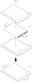
- the pouch-type secondary battery 1 may not structurally apply a gas hole as in a cylindrical or prismatic secondary battery, and as shown in FIG. 1 , it is formed of a structure in which the electrode assembly 2 is disposed between the upper pouch sheet 3 and the lower pouch sheet 4 and then four edges of the upper and lower pouch sheets 3, 4 are thermally fused to be sealed, whereby it is not easy to induce gas venting in a specific direction. Accordingly, it is required to develop a gas venting means suitable for a pouch-type secondary battery.
- the present disclosure is designed to solve the problems of the related art, and therefore the present disclosure is directed to reducing a risk factor by venting gas in a specific direction during swelling of a pouch-type secondary battery.
- a gas venting induction block including a block body having a slit to allow the cell terrace of a pouch-type secondary battery to be inserted to a predetermined depth; a pocket portion provided inside the block body and provided to accommodate a portion of the cell terrace in a form in which a space is expanded larger than the slit; and an exhaust pipe provided in a tubular shape and extending from the pocket portion to the outer surface of the block body, wherein the exhaust pipe includes a needle portion protruding sharply toward the inner space of the pocket portion so as to perforate the cell terrace when the cell terrace expands beyond a certain volume in the pocket portion.
- the block body may include a block upper portion and a block lower portion spaced apart vertically with the slit therebetween; and a block front portion having no slit and connected to the block upper portion and the block lower portion.
- the block upper portion and the block lower portion are vertically symmetrical, and the thickness of the middle region may be configured to be thinner than the thickness of both edge regions so that the pocket portion is provided.
- One end of the exhaust pipe corresponding to the needle portion may be located in the pocket portion and the other end of the exhaust pipe may be exposed to the outside of the block front portion via the inside of the block front portion.
- the exhaust pipe is plural and may include an upper exhaust pipe having the needle portion protruding from the block upper portion toward the pocket portion; and a lower exhaust pipe having the needle portion protruding from the block lower portion toward the pocket portion.
- the gas venting induction block may include a cell lead outlet having a size corresponding to the width and thickness of the electrode lead of the pouch-type secondary battery and provided to penetrate the block front portion to communicate with the pocket portion.
- the gas venting induction block may include two foam members disposed in the pocket portion and spaced apart vertically with the slit therebetween.
- the needle portion may be configured to be positioned within the foam member.
- a pouch-type secondary battery including the above-described gas venting induction block.
- a battery module including the above-described pouch-type secondary batteries.
- a gas venting induction block capable of suppressing an increase in internal pressure of the secondary battery by venting gas during swelling of the pouch-type secondary battery.
- internal gas may be ejected in a specific direction through the gas venting induction block during swelling of the secondary battery, thereby reducing a risk factor due to gas venting.
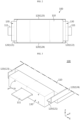
- FIG. 2 is a plan view of a pouch-type secondary battery according to an embodiment of the present disclosure
- FIG. 3 is a perspective view illustrating a portion of a pouch-type secondary battery according to an embodiment of the present disclosure.
- the pouch-type secondary battery 100 may be configured to include an electrode assembly, an electrode lead 111, a pouch case, and a gas venting induction block 130.
- the electrode assembly may include a positive electrode plate, a negative electrode plate, and a separator.
- the positive electrode plate may be formed by applying a positive electrode active material to a current collector plate made of aluminum (Al), and the negative electrode plate may be formed by applying a negative electrode active material to a current collector plate made of copper (Cu).
- the electrode assembly may be provided in a stack type formed by interposing a separator between the positive electrode plate and the negative electrode plate, or a jelly-roll type in which one positive electrode plate and one negative electrode plate are wound with a separator interposed therebetween.
- the electrode assembly may be provided in a stack-and-folding type in which a stack type and a jelly-roll type are mixed.
- the electrode lead 111 is a portion that is connected to the electrode assembly and extends to the outside of the pouch case, and may function as an electrode terminal capable of being electrically connected to other secondary batteries or external devices.
- the electrode lead 111 includes a positive electrode lead connected to the positive electrode plate and a negative electrode lead connected to the negative electrode plate, and the positive electrode lead and the negative electrode lead may be positioned in different directions as in the present embodiment or attached to the electrode assembly to be positioned in the same direction unlike the present embodiment.
- the pouch case may form a sealed space capable of accommodating and protecting the electrode assembly, the electrolyte, and the like, and may perform a heat dissipation function.
- the pouch case may be composed of an upper pouch sheet and a lower pouch sheet in the form of two laminate sheets.
- the upper and lower pouch sheets may include an outer insulating layer and an inner adhesive layer made of a polymer material, and a metal layer interposed between the outer insulating layer and the inner adhesive layer.
- aluminum (Al) may be used as a material for the metal layer.
- At least one of the upper pouch sheet and the lower pouch sheet may be provided to have a concavely formed space to accommodate the electrode assembly.
- the electrode assembly may be disposed in a formed space of the lower pouch sheet, and the upper pouch sheet may be overlapped on the lower pouch sheet.
- a sealing portion 120 may be formed along the edge lines of the four sides of the upper and lower pouch sheets.
- the sealing portion 120 may be defined as a portion in which the upper and lower pouch sheets are sealed by thermal fusion or the like.
- the portions of the sealing portion 120 where the electrode leads 111 protrude will be defined as cell terraces 121, 122, and the portions without the electrode leads 111 will be defined as side wings 123, 124. That is, in the pouch case, the sealing portion 120 on the short side corresponds to the cell terrace 121 and the sealing portion 120 on the long side corresponds to the side wings 123, 124.
- the portion surrounding the electrode assembly as an inner region based on the sealing portion 120 will be defined as the electrode accommodating portion 110. Folding the side wings 123, 124 and adhering to the side surface of the electrode accommodating portion may be advantageous in reducing the width of the secondary battery.
- the gas venting induction block 130 is a component that serves to reduce risk factors by making a hole in the expanded sealing portion 120 and allowing gas to be ejected in a specific direction when the pressure increases to reach a dangerous level due to gas generation of the pouch-type secondary battery 100.
- the gas venting induction block 130 includes a block body 131, a pocket portion 132, an exhaust pipe 133, and two foam members 135, 136.
- the gas venting induction block 130 may be configured such that the electrode lead 111 passes through the block body 131 and the cell terrace 121 is inserted into the block body 131 to a predetermined depth.
- the present embodiment is configured to allow the gas venting induction block 130 to be inserted into the cell terrace 121 based on the electrode lead 111.
- the gas venting induction block 130 may be inserted into the side wings 123, 124 of the pouch-type secondary battery 100, and in this case, the cell lead outlet O for withdrawing the electrode lead 111 may be omitted. A detailed description of the cell lead outlet O will be described later.
- the block body 131 constituting the gas venting induction block 130 is made of an insulating material such as plastic, and may be provided in a substantially rectangular parallelepiped shape as shown in FIG. 4 .
- the material of the block body 131 need not be necessarily limited to plastic.
- the block body 131 may be made of ceramic or the like as an insulating material.
- the thickness (Z-axis direction) of the block body 131 may correspond to the thickness of the pouch-type battery cell, the left-right length ( ⁇ X-axis direction) of the block body 131 may be shorter than the length from one end to the other end of the cell terrace 121, and the front-rear length of the block body 131 may be longer than the protruding length (-Y-axis direction) of the cell terrace 121 and shorter than the protruding length of the electrode lead 111.
- the block body 131 includes a slit S formed in a direction crossing the thickness direction so that the cell terrace 121 may be inserted into the inside.
- the slit S is formed by the protruding length of the cell terrace 121 from the rear of the block body 131 toward the front.
- the block body 131 may be provided in a form in which the rear portion is bisected up and down.
- the block body 131 includes a block upper portion 131a and a block lower portion 131b spaced vertically with the slit S therebetween, and a block front portion 131c connecting the block upper portion 131a and the block lower portion 131b as a portion without the slit S and having the cell lead outlet O through which the electrode lead 111 may be withdrawn.
- the pocket portion 132 is a portion provided to have a space expanded larger than the slit S inside the block body 131 so that the cell terrace 121 may expand inside the block body 131 when gas is generated in the pouch-type secondary battery 100.
- the pocket portion 132 expanded larger than the slit S may be provided between the block upper portion 131a and the block lower portion 131b.
- the cell lead outlet O may be provided penetrating the block front portion 131c in a size corresponding to the width and thickness of the electrode lead 111 as shown in FIG. 4 (a) and may be provided to communicate with the pocket portion 132 (in the Y-axis direction) inside the block body 131 as shown in FIG. 4 (b) .
- the cell terrace 121 may be inserted into a portion where the slit S is formed in the block body 131, that is, between the block upper portion 131a and the block lower portion 131b, and the electrode lead 111 may be withdrawn to the outside of the block front portion 131c through the cell lead outlet O.
- a portion of the cell terrace 121 may be accommodated in the pocket portion 132 and the remaining portion may be exposed to the outside of both side surfaces of the block body 131.
- both edge portions of the cell terrace 121 may be folded together with the side wings 123, 124 to be in close contact with the side surface of the electrode accommodating portion 110.
- the exhaust pipe 133 may be provided in a tubular shape as a component for making a hole in the cell terrace 121 when the cell terrace 121 accommodated in the pocket portion 132 expands and directing the gas ejected from the cell terrace 121 in a specific direction, and may be configured to extend from the pocket portion 132 to the outer surface of the block body 131.
- the exhaust pipe 133 may be configured such that one end is located in the pocket portion 132 and the other end P is exposed to the outside of the block front portion 131c via the inside of the block front portion 131c.
- the exhaust pipe 133 may include a needle portion 134 protruding sharply toward the inner space of the pocket portion 132 so that the cell terrace 121 may be perforated when the cell terrace 121 expands beyond a certain volume in the pocket portion 132.
- the gas venting induction block 130 of the present embodiment has a plurality of exhaust pipes 133, and the plurality of exhaust pipes 133 include two upper exhaust pipes 133a having needle portions 134 protruding downward from the block upper portion 131a toward the pocket portion 132 and two lower exhaust pipes 133b having needle portions 134 protruding upward from the block lower portion 131b toward the pocket portion 132.
- the two upper exhaust pipes 133a may be configured to be provided one by one in the left-right direction ( ⁇ X-axis direction) based on the cell lead outlet O and to be exposed to the outside of the block front portion 131c via the inside of the block upper portion 131a and the block front portion 131c, respectively.
- the two lower exhaust pipes 133b may be configured to be provided one by one in the left-right direction ( ⁇ X-axis direction) based on the cell lead outlet O and to be exposed to the outside of the block front portion 131c via the inside of the block lower portion 131b and the block front portion 131c, respectively.
- the above-described exhaust pipe 133 may be made of a metal material such as stainless and may be integrally manufactured with the block body 131 by an insert injection molding method.
- the scope of the present disclosure is not limited to the material of the exhaust pipe 133 or the manufacturing method.
- the exhaust pipe 133 may be made of the same material as the block body 131 and may be injection molded in a form integrated with the block body 131.
- the gas venting induction block 130 may further include two form members disposed in the pocket portion 132 and vertically spaced apart with the slit S therebetween.
- the electrode lead 111 and the cell terrace 121 When the electrode lead 111 and the cell terrace 121 are inserted into the block body 131, the electrode lead 111 or the cell terrace 121 may be in contact with the needle portion 134 to be damaged.
- the two foam members 135, 136 are components for preventing the electrode lead 111 or the cell terrace 121 from being damaged unexpectedly in this way.
- the two foam members 135, 136 may be made of an elastic material such as sponge or memory foam, and as shown in FIG. 6 , with the slit S interposed therebetween in the pocket portion 132, one may be attached to the inner surface of block upper portion 131a and the other may be attached to the inner surface of the block lower portion 131b.
- the foam members 135, 136 are adhered in an upward direction (+Z-axis direction) toward the inner surface of the block upper portion 131a or in a downward direction (-Z-axis direction) toward the inner surface of the block lower portion 131b so that the needle portion 134 is inserted into the foam members 135, 136. Thereafter, compression of the foam members 135, 136 is released so that the foam members 135, 136 are restored to their original volume.
- the foam members 135, 136 may be held in contact with the inner surface of the block upper portion 131a or the inner surface of the block lower portion 131b.
- the vertical distance between the two foam members 135 and 136 is at least greater than the slit S, and the needle portion 134 may be configured to be positioned in a state of being embedded in the foam members 135, 136.
- the foam members 135, 136 may be compressed by pressure. Furthermore, when the cell terrace 121 reaches a state expanded above a certain volume, a hole may be made by the needle portion 134.
- foam members 135, 136 foam members 135, 136 having different degrees of compressibility, such as ethylene vinyl acetate (EVA) foam, synthetic latex, polystyrene foam (Styrofoam), sponge, and the like may be selectively used.
- EVA ethylene vinyl acetate
- Styrofoam synthetic latex
- sponge polystyrene foam
- the needle portion 134 and the cell terrace 121 may contact each other only when the expansion force of the cell terrace 121 is higher than a certain level, and thus gas may be discharged.
- FIG. 8 is a cross-sectional view of the gas venting induction block 130 region when a pouch-type secondary battery 100 of the present disclosure is in normal
- FIG. 9 is a cross-sectional view of the gas venting induction block 130 region when a pouch-type secondary battery 100 of the present disclosure is swelling.
- a gas discharge mechanism of the pouch-type secondary battery 100 by the gas venting induction block 130 will be briefly described as follows.
- the electrode lead 111 passes through the gas venting induction block 130 and is withdrawn in the -Y-axis direction, and the cell terrace 121 may be inserted into the gas venting induction block 130 so that a portion thereof is accommodated in the pocket portion 132 of the block body 131.
- the cell terrace 121 is spaced apart from the needle portion 134 by a predetermined distance and is blocked by the two foam members 135, 136 in the vertical direction even if it moves somewhat due to external shock or vibration, so it is not in contact with the needle portion 134.
- the cell terrace 121 may swell and the foam members 135, 136 may be compressed. Furthermore, when the expansion of the cell terrace 121 intensifies and the degree of expansion reaches a certain volume or more, the needle portion 134 of the exhaust pipe 133 may make a hole in the cell terrace 121 and be inserted into the cell terrace 121 as shown in FIG. 9 . As a result, the gas in the cell terrace 121 may flow into the inside of the needle portion 134 and move along the inside of the exhaust pipe 133 to be ejected to the outside of the block front portion 131c.
- the internal pressure may be lowered by discharging the gas to the outside before the secondary battery reaches an explosion stage due to an increase in internal pressure, thereby preventing the secondary battery from exploding.
- the sealing portion 120 of the pouch case is damaged in an unspecified manner, thereby preventing the gas from being ejected in an unspecified direction. That is, in the present embodiment, since gas is discharged in a specific direction by the gas venting induction block 130, the gas discharge location may be fully expected, thereby reducing risk factors due to gas discharge.
- the pouch-type secondary battery 100 by ejecting gas in the direction of the electrode lead 111 of the pouch-type secondary battery 100, it may be easy to collect the gas ejected from each pouch-type secondary battery 100 when manufacturing the battery module, and the application of an exhaust system configuration for safely discharging the collected gas to the outside may be facilitated.
- FIG. 10 is a view illustrating a portion of a battery module according to an embodiment of the present disclosure.
- the battery module according to an embodiment of the present disclosure shown in FIG. 10 may be configured in a form in which the above-described pouch-type secondary batteries 100 are vertically erected and stacked in the left-right direction.
- a plurality of bus bars made of metal materials such as copper are used as a component for electrically connecting the pouch-type secondary batteries, and a bus bar frame in the form of a plate body is included to support the plurality of bus bars.
- the battery module according to the present disclosure may be configured to omit the bus bar frame, assemble the gas venting induction blocks 130 of the pouch-type secondary battery 100 in one direction in an adhesive or snap-fit coupling method, and mount the bus bars 200 on the block front portion 131c of the gas venting induction block 130.
- the gas venting induction block 130 may be configured to form a bus bar groove in which one bus bar 200 may be partially inserted and fixed.
- the pouch-type secondary batteries 100 may be electrically connected by bending and welding the positive electrode lead of one pouch-type secondary battery 100 and the negative electrode lead of the other pouch-type secondary battery 100 on one bus bar attached across the two gas venting induction blocks 130.
- the battery module of the present disclosure may be configured to safely discharge gas generated in the secondary batteries out of the battery module by adding holes through which gas is discharged from the gas venting induction blocks 130, that is, a gas pipe (not shown) that may be connected to the other ends of the exhaust pipe 133.
- the gas pipe may be implemented in the form of a manifold having a plurality of intake ports and a single exhaust port.
- the battery module of the present disclosure may be configured to further include various devices (not shown) for controlling charge/discharge of the pouch-type secondary batteries 100, for example, a battery management system (BMS), a current sensor, a fuse, and the like, and a module housing for accommodating the pouch-type secondary batteries 100 and the various devices.
- various devices for controlling charge/discharge of the pouch-type secondary batteries 100, for example, a battery management system (BMS), a current sensor, a fuse, and the like, and a module housing for accommodating the pouch-type secondary batteries 100 and the various devices.
- BMS battery management system
Landscapes
- Chemical & Material Sciences (AREA)
- Chemical Kinetics & Catalysis (AREA)
- Electrochemistry (AREA)
- General Chemical & Material Sciences (AREA)
- Gas Exhaust Devices For Batteries (AREA)
- Sealing Battery Cases Or Jackets (AREA)
Abstract
Description
- The present disclosure relates to a pouch-type secondary battery, and a device for discharging internal gas in a specific direction during swelling of the pouch-type secondary battery.
- The present application claims priority to
Korean Patent Application No. 10-2021-0142201 filed on October 22, 2021 - In general, a secondary battery means a battery capable of charge/discharge, unlike a primary battery that may not be charged, and is widely used in electronic devices such as mobile phones, laptop computers, camcorders, and the like, or electric vehicles. In particular, since a lithium secondary battery has a larger capacity than a nickel-cadmium battery or a nickel-hydrogen battery, which is widely used as a power source for electronic equipment, and has a high energy density per unit weight, the degree of utilization thereof is rapidly increasing.
- When a secondary battery is overcharged or a sudden change occurs in the electrical environment, an electrolyte may be decomposed at the positive electrode and lithium metal may be deposited at the negative electrode, and in the case of occurrence of such phenomenon, the performance of the secondary battery may be downgraded. In addition, a secondary battery uses, for example, a solvent such as ethylene carbonate or propylene carbonate as an electrolyte, but these solvents are decomposed at a high temperature to generate gas, and thus it causes an increase in pressure, whereby a swelling phenomenon that is a kind of inflating phenomenon may occur, resulting in serious problems such as explosion of the secondary battery.
- Accordingly, the present applicant is seeking a method of removing the risk factor of the secondary battery by inducing gas venting in a specific direction before the internal pressure of the secondary battery increases to reach an explosion risk stage.
- For example, Korean Patent Publication No.
KR 10-2018-0075797 - However, the pouch-type
secondary battery 1 may not structurally apply a gas hole as in a cylindrical or prismatic secondary battery, and as shown inFIG. 1 , it is formed of a structure in which theelectrode assembly 2 is disposed between theupper pouch sheet 3 and thelower pouch sheet 4 and then four edges of the upper andlower pouch sheets - The present disclosure is designed to solve the problems of the related art, and therefore the present disclosure is directed to reducing a risk factor by venting gas in a specific direction during swelling of a pouch-type secondary battery.
- Other objects and advantages of the present disclosure will be described below, and will be learned by embodiments of the present disclosure. In addition, the objects and advantages of the present disclosure may be realized by configurations and a combination of configurations shown in the claims.
- According to the present disclosure, there may be provided a gas venting induction block including a block body having a slit to allow the cell terrace of a pouch-type secondary battery to be inserted to a predetermined depth; a pocket portion provided inside the block body and provided to accommodate a portion of the cell terrace in a form in which a space is expanded larger than the slit; and an exhaust pipe provided in a tubular shape and extending from the pocket portion to the outer surface of the block body, wherein the exhaust pipe includes a needle portion protruding sharply toward the inner space of the pocket portion so as to perforate the cell terrace when the cell terrace expands beyond a certain volume in the pocket portion.
- The block body may include a block upper portion and a block lower portion spaced apart vertically with the slit therebetween; and a block front portion having no slit and connected to the block upper portion and the block lower portion.
- The block upper portion and the block lower portion are vertically symmetrical, and the thickness of the middle region may be configured to be thinner than the thickness of both edge regions so that the pocket portion is provided.
- One end of the exhaust pipe corresponding to the needle portion may be located in the pocket portion and the other end of the exhaust pipe may be exposed to the outside of the block front portion via the inside of the block front portion.
- The exhaust pipe is plural and may include an upper exhaust pipe having the needle portion protruding from the block upper portion toward the pocket portion; and a lower exhaust pipe having the needle portion protruding from the block lower portion toward the pocket portion.
- The gas venting induction block may include a cell lead outlet having a size corresponding to the width and thickness of the electrode lead of the pouch-type secondary battery and provided to penetrate the block front portion to communicate with the pocket portion.
- The gas venting induction block may include two foam members disposed in the pocket portion and spaced apart vertically with the slit therebetween.
- The needle portion may be configured to be positioned within the foam member.
- According to another aspect of the present disclosure, there may be provided a pouch-type secondary battery including the above-described gas venting induction block.
- According to still another aspect of the present disclosure, there may be provided a battery module including the above-described pouch-type secondary batteries.
- According to one aspect of the present disclosure, there may be provided a gas venting induction block capable of suppressing an increase in internal pressure of the secondary battery by venting gas during swelling of the pouch-type secondary battery. In particular, internal gas may be ejected in a specific direction through the gas venting induction block during swelling of the secondary battery, thereby reducing a risk factor due to gas venting.
- Advantageous effects to be obtained by the present disclosure are not limited to the above-described effects, and other effects not mentioned herein may be clearly understood by those skilled in the art from the following description of the present disclosure.
-
-
FIG. 1 is a view schematically illustrating the configuration of a pouch-type secondary battery according to the prior art. -
FIG. 2 is a plan view of a pouch-type secondary battery according to an embodiment of the present disclosure. -
FIG. 3 is a perspective view illustrating a portion of a pouch-type secondary battery according to an embodiment of the present disclosure. -
FIG. 4 (a) is a perspective view of a gas venting induction block according to an embodiment of the present disclosure, andFIG. 4 (b) is a partially cut-away perspective view of the gas venting induction block. -
FIG. 5 is a front view of the gas venting induction block ofFIG. 4 (a) . -
FIG. 6 is a rear view of the gas venting induction block ofFIG. 4 (a) . -
FIG. 7 is a side view of the gas venting induction block ofFIG. 4 (a) . -
FIG. 8 is a cross-sectional view of the gas venting induction block region when a pouch-type secondary battery of the present disclosure is in normal. -
FIG. 9 is a cross-sectional view of the gas venting induction block region when a pouch-type secondary battery of the present disclosure is swelling. -
FIG. 10 is a view illustrating a portion of a battery module according to an embodiment of the present disclosure. - Hereinafter, preferred embodiments of the present disclosure will be described in detail with reference to the accompanying drawings. Prior to the description, the shapes and sizes of components in the drawings may be exaggerated, omitted, or schematically illustrated for clearer description. Accordingly, the size or proportion of each component does not fully reflect the actual size or proportion. In addition, it should be understood that the terms used in the specification and the appended claims should not be construed as limited to general and dictionary meanings, but interpreted based on the meanings and concepts corresponding to technical aspects of the present disclosure on the basis of the principle that the inventor is allowed to define terms appropriately for the best explanation.
- Therefore, the description proposed herein is just a preferable example for the purpose of illustrations only, not intended to limit the scope of the present disclosure, so it should be understood that other equivalents and modifications could be made thereto without departing from the scope of the present disclosure. In addition, if it is determined that a detailed description of a related known configuration or function may obscure the gist of the present disclosure in describing the present disclosure, such a detailed description will be omitted.
-
FIG. 2 is a plan view of a pouch-type secondary battery according to an embodiment of the present disclosure, andFIG. 3 is a perspective view illustrating a portion of a pouch-type secondary battery according to an embodiment of the present disclosure. - The pouch-type
secondary battery 100 according to an embodiment of the present disclosure may be configured to include an electrode assembly, anelectrode lead 111, a pouch case, and a gasventing induction block 130. - The electrode assembly may include a positive electrode plate, a negative electrode plate, and a separator. The positive electrode plate may be formed by applying a positive electrode active material to a current collector plate made of aluminum (Al), and the negative electrode plate may be formed by applying a negative electrode active material to a current collector plate made of copper (Cu). The electrode assembly may be provided in a stack type formed by interposing a separator between the positive electrode plate and the negative electrode plate, or a jelly-roll type in which one positive electrode plate and one negative electrode plate are wound with a separator interposed therebetween. Of course, the scope of the present disclosure should not be limited thereto. For example, the electrode assembly may be provided in a stack-and-folding type in which a stack type and a jelly-roll type are mixed.
- The
electrode lead 111 is a portion that is connected to the electrode assembly and extends to the outside of the pouch case, and may function as an electrode terminal capable of being electrically connected to other secondary batteries or external devices. Theelectrode lead 111 includes a positive electrode lead connected to the positive electrode plate and a negative electrode lead connected to the negative electrode plate, and the positive electrode lead and the negative electrode lead may be positioned in different directions as in the present embodiment or attached to the electrode assembly to be positioned in the same direction unlike the present embodiment. - The pouch case may form a sealed space capable of accommodating and protecting the electrode assembly, the electrolyte, and the like, and may perform a heat dissipation function.
- Although not shown in detail for convenience of drawings, the pouch case may be composed of an upper pouch sheet and a lower pouch sheet in the form of two laminate sheets. The upper and lower pouch sheets may include an outer insulating layer and an inner adhesive layer made of a polymer material, and a metal layer interposed between the outer insulating layer and the inner adhesive layer. Here, aluminum (Al) may be used as a material for the metal layer.
- At least one of the upper pouch sheet and the lower pouch sheet may be provided to have a concavely formed space to accommodate the electrode assembly. For example, the electrode assembly may be disposed in a formed space of the lower pouch sheet, and the upper pouch sheet may be overlapped on the lower pouch sheet. In addition, a sealing
portion 120 may be formed along the edge lines of the four sides of the upper and lower pouch sheets. Here, the sealingportion 120 may be defined as a portion in which the upper and lower pouch sheets are sealed by thermal fusion or the like. - Hereinafter, the portions of the sealing
portion 120 where the electrode leads 111 protrude will be defined ascell terraces side wings portion 120 on the short side corresponds to thecell terrace 121 and the sealingportion 120 on the long side corresponds to theside wings portion 120 will be defined as theelectrode accommodating portion 110. Folding theside wings - The gas
venting induction block 130 is a component that serves to reduce risk factors by making a hole in the expanded sealingportion 120 and allowing gas to be ejected in a specific direction when the pressure increases to reach a dangerous level due to gas generation of the pouch-typesecondary battery 100. - Hereinafter, the configuration of the gas venting
induction block 130 will be described in detail with reference toFIGS. 3 to 7 . - The gas
venting induction block 130 according to an embodiment of the present disclosure includes ablock body 131, apocket portion 132, anexhaust pipe 133, and twofoam members - As shown in
FIG. 3 , the gas ventinginduction block 130 may be configured such that theelectrode lead 111 passes through theblock body 131 and thecell terrace 121 is inserted into theblock body 131 to a predetermined depth. - In general, in the case of the pouch-type
secondary battery 100, when the internal pressure increases, the sealing of thecell terraces side wings cell terraces induction block 130 to be inserted into thecell terrace 121 based on theelectrode lead 111. Of course, unlike the present embodiment, the gas ventinginduction block 130 may be inserted into theside wings secondary battery 100, and in this case, the cell lead outlet O for withdrawing theelectrode lead 111 may be omitted. A detailed description of the cell lead outlet O will be described later. - Specifically, the
block body 131 constituting the gas ventinginduction block 130 is made of an insulating material such as plastic, and may be provided in a substantially rectangular parallelepiped shape as shown inFIG. 4 . Of course, the material of theblock body 131 need not be necessarily limited to plastic. For example, theblock body 131 may be made of ceramic or the like as an insulating material. - The thickness (Z-axis direction) of the
block body 131 may correspond to the thickness of the pouch-type battery cell, the left-right length (±X-axis direction) of theblock body 131 may be shorter than the length from one end to the other end of thecell terrace 121, and the front-rear length of theblock body 131 may be longer than the protruding length (-Y-axis direction) of thecell terrace 121 and shorter than the protruding length of theelectrode lead 111. - The
block body 131 includes a slit S formed in a direction crossing the thickness direction so that thecell terrace 121 may be inserted into the inside. The slit S is formed by the protruding length of thecell terrace 121 from the rear of theblock body 131 toward the front. By such a slit S, theblock body 131 may be provided in a form in which the rear portion is bisected up and down. - Accordingly, the
block body 131 includes a blockupper portion 131a and a blocklower portion 131b spaced vertically with the slit S therebetween, and ablock front portion 131c connecting the blockupper portion 131a and the blocklower portion 131b as a portion without the slit S and having the cell lead outlet O through which theelectrode lead 111 may be withdrawn. - The
pocket portion 132 is a portion provided to have a space expanded larger than the slit S inside theblock body 131 so that thecell terrace 121 may expand inside theblock body 131 when gas is generated in the pouch-typesecondary battery 100. - For example, referring to
FIGS. 4 and6 , since the blockupper portion 131a and the blocklower portion 131b are vertically symmetrical and the thickness of the middle region is smaller than the thickness of both edge regions, thepocket portion 132 expanded larger than the slit S may be provided between the blockupper portion 131a and the blocklower portion 131b. - The cell lead outlet O may be provided penetrating the
block front portion 131c in a size corresponding to the width and thickness of theelectrode lead 111 as shown inFIG. 4 (a) and may be provided to communicate with the pocket portion 132 (in the Y-axis direction) inside theblock body 131 as shown inFIG. 4 (b) . - According to the above configuration, as shown in
FIG. 3 , thecell terrace 121 may be inserted into a portion where the slit S is formed in theblock body 131, that is, between the blockupper portion 131a and the blocklower portion 131b, and theelectrode lead 111 may be withdrawn to the outside of theblock front portion 131c through the cell lead outlet O. A portion of thecell terrace 121 may be accommodated in thepocket portion 132 and the remaining portion may be exposed to the outside of both side surfaces of theblock body 131. In addition, both edge portions of thecell terrace 121 may be folded together with theside wings electrode accommodating portion 110. - As described above, the
exhaust pipe 133 may be provided in a tubular shape as a component for making a hole in thecell terrace 121 when thecell terrace 121 accommodated in thepocket portion 132 expands and directing the gas ejected from thecell terrace 121 in a specific direction, and may be configured to extend from thepocket portion 132 to the outer surface of theblock body 131. - For example, as shown in
FIG. 4 (a) , theexhaust pipe 133 may be configured such that one end is located in thepocket portion 132 and the other end P is exposed to the outside of theblock front portion 131c via the inside of theblock front portion 131c. - In addition, the
exhaust pipe 133 may include aneedle portion 134 protruding sharply toward the inner space of thepocket portion 132 so that thecell terrace 121 may be perforated when thecell terrace 121 expands beyond a certain volume in thepocket portion 132. - The gas venting induction block 130 of the present embodiment has a plurality of
exhaust pipes 133, and the plurality ofexhaust pipes 133 include twoupper exhaust pipes 133a havingneedle portions 134 protruding downward from the blockupper portion 131a toward thepocket portion 132 and twolower exhaust pipes 133b havingneedle portions 134 protruding upward from the blocklower portion 131b toward thepocket portion 132. - The two
upper exhaust pipes 133a may be configured to be provided one by one in the left-right direction (±X-axis direction) based on the cell lead outlet O and to be exposed to the outside of theblock front portion 131c via the inside of the blockupper portion 131a and theblock front portion 131c, respectively. In addition, the twolower exhaust pipes 133b may be configured to be provided one by one in the left-right direction (±X-axis direction) based on the cell lead outlet O and to be exposed to the outside of theblock front portion 131c via the inside of the blocklower portion 131b and theblock front portion 131c, respectively. - The above-described
exhaust pipe 133 may be made of a metal material such as stainless and may be integrally manufactured with theblock body 131 by an insert injection molding method. However, the scope of the present disclosure is not limited to the material of theexhaust pipe 133 or the manufacturing method. For example, theexhaust pipe 133 may be made of the same material as theblock body 131 and may be injection molded in a form integrated with theblock body 131. - Meanwhile, the gas venting
induction block 130 according to the present embodiment may further include two form members disposed in thepocket portion 132 and vertically spaced apart with the slit S therebetween. - When the
electrode lead 111 and thecell terrace 121 are inserted into theblock body 131, theelectrode lead 111 or thecell terrace 121 may be in contact with theneedle portion 134 to be damaged. The twofoam members electrode lead 111 or thecell terrace 121 from being damaged unexpectedly in this way. - The two
foam members FIG. 6 , with the slit S interposed therebetween in thepocket portion 132, one may be attached to the inner surface of blockupper portion 131a and the other may be attached to the inner surface of the blocklower portion 131b. - For example, after pushing the
foam members foam members upper portion 131a or in a downward direction (-Z-axis direction) toward the inner surface of the blocklower portion 131b so that theneedle portion 134 is inserted into thefoam members foam members foam members needle portions 134 are embedded in thefoam members foam members upper portion 131a or the inner surface of the blocklower portion 131b. Here, the vertical distance between the twofoam members needle portion 134 may be configured to be positioned in a state of being embedded in thefoam members - Therefore, in the process of pushing the
electrode lead 111 and thecell terrace 121 into thepocket portion 132, there is no fear of damage to theelectrode lead 111 or thecell terrace 121. In this way, when gas is generated in the pouch-typesecondary battery 100 in a state where thecell terrace 121 is positioned in thepocket portion 132 and thecell terrace 121 expands, thefoam members cell terrace 121 reaches a state expanded above a certain volume, a hole may be made by theneedle portion 134. - As the
foam members foam members foam members needle portion 134 and thecell terrace 121 may contact each other only when the expansion force of thecell terrace 121 is higher than a certain level, and thus gas may be discharged. -
FIG. 8 is a cross-sectional view of the gas venting induction block 130 region when a pouch-typesecondary battery 100 of the present disclosure is in normal, andFIG. 9 is a cross-sectional view of the gas venting induction block 130 region when a pouch-typesecondary battery 100 of the present disclosure is swelling. - Referring to
FIGS. 8 and 9 , a gas discharge mechanism of the pouch-typesecondary battery 100 by the gas ventinginduction block 130 will be briefly described as follows. - As shown in
FIG. 8 , theelectrode lead 111 passes through the gas ventinginduction block 130 and is withdrawn in the -Y-axis direction, and thecell terrace 121 may be inserted into the gas ventinginduction block 130 so that a portion thereof is accommodated in thepocket portion 132 of theblock body 131. Normally, thecell terrace 121 is spaced apart from theneedle portion 134 by a predetermined distance and is blocked by the twofoam members needle portion 134. - However, when the internal pressure of the pouch-type
secondary battery 100 increases due to gas generation, thecell terrace 121 may swell and thefoam members cell terrace 121 intensifies and the degree of expansion reaches a certain volume or more, theneedle portion 134 of theexhaust pipe 133 may make a hole in thecell terrace 121 and be inserted into thecell terrace 121 as shown inFIG. 9 . As a result, the gas in thecell terrace 121 may flow into the inside of theneedle portion 134 and move along the inside of theexhaust pipe 133 to be ejected to the outside of theblock front portion 131c. - According to this configuration of the present embodiment, when gas is generated in the pouch-type
secondary battery 100 due to a situation such as thermal runaway, the internal pressure may be lowered by discharging the gas to the outside before the secondary battery reaches an explosion stage due to an increase in internal pressure, thereby preventing the secondary battery from exploding. - In addition, when gas is generated, the sealing
portion 120 of the pouch case is damaged in an unspecified manner, thereby preventing the gas from being ejected in an unspecified direction. That is, in the present embodiment, since gas is discharged in a specific direction by the gas ventinginduction block 130, the gas discharge location may be fully expected, thereby reducing risk factors due to gas discharge. - For example, as in this embodiment, by ejecting gas in the direction of the
electrode lead 111 of the pouch-typesecondary battery 100, it may be easy to collect the gas ejected from each pouch-typesecondary battery 100 when manufacturing the battery module, and the application of an exhaust system configuration for safely discharging the collected gas to the outside may be facilitated. - Next, with reference to
FIG. 10 , a battery module according to an embodiment of the present disclosure including the above-described pouch-typesecondary batteries 100 will be briefly described. -
FIG. 10 is a view illustrating a portion of a battery module according to an embodiment of the present disclosure. - The battery module according to an embodiment of the present disclosure shown in
FIG. 10 may be configured in a form in which the above-described pouch-typesecondary batteries 100 are vertically erected and stacked in the left-right direction. In the case of a battery module composed of pouch-type secondary batteries according to the prior art, a plurality of bus bars made of metal materials such as copper are used as a component for electrically connecting the pouch-type secondary batteries, and a bus bar frame in the form of a plate body is included to support the plurality of bus bars. However, the battery module according to the present disclosure may be configured to omit the bus bar frame, assemble the gas venting induction blocks 130 of the pouch-typesecondary battery 100 in one direction in an adhesive or snap-fit coupling method, and mount the bus bars 200 on theblock front portion 131c of the gas ventinginduction block 130. - For example, although not shown in the above-described embodiment, when a region of the
block front portion 131c of each gas ventinginduction block 130 is processed and two gas venting induction blocks 130 are combined as shown inFIG. 10 , the gas ventinginduction block 130 may be configured to form a bus bar groove in which onebus bar 200 may be partially inserted and fixed. In this case, the pouch-typesecondary batteries 100 may be electrically connected by bending and welding the positive electrode lead of one pouch-typesecondary battery 100 and the negative electrode lead of the other pouch-typesecondary battery 100 on one bus bar attached across the two gas venting induction blocks 130. - Although not shown, the battery module of the present disclosure may be configured to safely discharge gas generated in the secondary batteries out of the battery module by adding holes through which gas is discharged from the gas venting induction blocks 130, that is, a gas pipe (not shown) that may be connected to the other ends of the
exhaust pipe 133. Here, the gas pipe may be implemented in the form of a manifold having a plurality of intake ports and a single exhaust port. - In addition, the battery module of the present disclosure may be configured to further include various devices (not shown) for controlling charge/discharge of the pouch-type
secondary batteries 100, for example, a battery management system (BMS), a current sensor, a fuse, and the like, and a module housing for accommodating the pouch-typesecondary batteries 100 and the various devices. - Meanwhile, the terms indicating directions as used herein such as upper, lower, left, right, front, and rear are used for convenience of description only, and it is obvious to those skilled in the art that the terms may change depending on the position of the stated element or an observer.
- While the present disclosure has been hereinabove described with regard to a limited number of embodiments and drawings, the present disclosure is not limited thereto and it is obvious to those skilled in the art that a variety of modifications and changes may be made thereto within the technical aspects of the present disclosure and the equivalent scope of the appended claims.
Claims (10)
- A gas venting induction block comprising:a block body having a slit to allow the cell terrace of a pouch-type secondary battery to be inserted to a predetermined depth;a pocket portion provided inside the block body and provided to accommodate a portion of the cell terrace in a form in which a space is expanded larger than the slit; andan exhaust pipe provided in a tubular shape and extending from the pocket portion to the outer surface of the block body,wherein the exhaust pipe comprises a needle portion protruding sharply toward the inner space of the pocket portion so as to perforate the cell terrace when the cell terrace expands beyond a certain volume in the pocket portion.
- The gas venting induction block according to claim 1,
wherein the block body comprises:a block upper portion and a block lower portion spaced apart vertically with the slit therebetween; anda block front portion having no slit and connected to the block upper portion and the block lower portion. - The gas venting induction block according to claim 2,
wherein the block upper portion and the block lower portion are vertically symmetrical, and the thickness of the middle region is configured to be thinner than the thickness of both edge regions so that the pocket portion is provided. - The gas venting induction block according to claim 2,
wherein one end of the exhaust pipe corresponding to the needle portion is located in the pocket portion and the other end of the exhaust pipe is exposed to the outside of the block front portion via the inside of the block front portion. - The gas venting induction block according to claim 4,
wherein the exhaust pipe is plural and comprises:an upper exhaust pipe having the needle portion protruding from the block upper portion toward the pocket portion; anda lower exhaust pipe having the needle portion protruding from the block lower portion toward the pocket portion. - The gas venting induction block according to claim 2,
which comprises a cell lead outlet having a size corresponding to the width and thickness of the electrode lead of the pouch-type secondary battery and provided to penetrate the block front portion to communicate with the pocket portion. - The gas venting induction block according to claim 1,
which comprises two foam members disposed in the pocket portion and spaced apart vertically with the slit therebetween. - The gas venting induction block according to claim 7,
wherein the needle portion is configured to be positioned within the foam member. - A pouch-type secondary battery comprising the gas venting induction block according to any one of claims 1 to 8.
- A battery module comprising the pouch-type secondary batteries according to claim 9.
Applications Claiming Priority (2)
| Application Number | Priority Date | Filing Date | Title |
|---|---|---|---|
| KR1020210142201A KR102885209B1 (en) | 2021-10-22 | 2021-10-22 | Gas venting induction block and pouch-type secondary battery including the same |
| PCT/KR2022/015527 WO2023068659A1 (en) | 2021-10-22 | 2022-10-13 | Gas venting guide block and pouch type secondary battery comprising same |
Publications (3)
| Publication Number | Publication Date |
|---|---|
| EP4318771A1 true EP4318771A1 (en) | 2024-02-07 |
| EP4318771A4 EP4318771A4 (en) | 2024-09-25 |
| EP4318771B1 EP4318771B1 (en) | 2025-06-25 |
Family
ID=86058338
Family Applications (1)
| Application Number | Title | Priority Date | Filing Date |
|---|---|---|---|
| EP22883882.7A Active EP4318771B1 (en) | 2021-10-22 | 2022-10-13 | Gas venting induction block and pouch-type secondary battery including the same |
Country Status (8)
| Country | Link |
|---|---|
| US (1) | US20240178510A1 (en) |
| EP (1) | EP4318771B1 (en) |
| JP (1) | JP7674508B2 (en) |
| KR (1) | KR102885209B1 (en) |
| CN (1) | CN117044024A (en) |
| ES (1) | ES3037501T3 (en) |
| HU (1) | HUE072342T2 (en) |
| WO (1) | WO2023068659A1 (en) |
Family Cites Families (12)
| Publication number | Priority date | Publication date | Assignee | Title |
|---|---|---|---|---|
| JPH0950799A (en) * | 1995-08-04 | 1997-02-18 | Sony Corp | Safety valve device and non-aqueous electrolyte secondary battery |
| JP4154888B2 (en) * | 2001-12-03 | 2008-09-24 | 日産自動車株式会社 | Battery module and vehicle equipped with battery module |
| JP5255210B2 (en) * | 2004-11-30 | 2013-08-07 | 日本電気株式会社 | Film-covered electrical device case and method for producing the film-covered electrical device case |
| JP2007141778A (en) * | 2005-11-22 | 2007-06-07 | Toyota Motor Corp | Batteries and batteries |
| JP2010186786A (en) * | 2009-02-10 | 2010-08-26 | Fdk Corp | Electrical storage device and electrical storage device module |
| KR101093937B1 (en) * | 2009-11-26 | 2011-12-13 | 삼성에스디아이 주식회사 | Secondary Battery and Battery Pack Using the Same |
| JP5404527B2 (en) * | 2010-05-24 | 2014-02-05 | Fdk株式会社 | Storage module with explosion-proof function |
| KR20120136750A (en) * | 2011-06-10 | 2012-12-20 | 에스케이이노베이션 주식회사 | Battery having venting structure |
| KR20150023114A (en) * | 2013-08-22 | 2015-03-05 | 주식회사 엘지화학 | Battery pack having gas discharge pipe |
| KR101730576B1 (en) * | 2016-06-17 | 2017-04-26 | 주식회사 엘지화학 | Battery cell and battery module comprising it |
| KR20180075797A (en) | 2016-12-27 | 2018-07-05 | 주식회사 엘지화학 | Cap Assembly for Cylindrical Battery Cell Comprising Current Interrupt Device Coupled to Safety Vent by Electrical Insulating Material |
| US11343524B2 (en) | 2019-12-27 | 2022-05-24 | Tencent America LLC | Method for adaptation parameter set reference and constraints in coded video stream |
-
2021
- 2021-10-22 KR KR1020210142201A patent/KR102885209B1/en active Active
-
2022
- 2022-10-13 WO PCT/KR2022/015527 patent/WO2023068659A1/en not_active Ceased
- 2022-10-13 US US18/283,426 patent/US20240178510A1/en active Pending
- 2022-10-13 ES ES22883882T patent/ES3037501T3/en active Active
- 2022-10-13 JP JP2023556840A patent/JP7674508B2/en active Active
- 2022-10-13 EP EP22883882.7A patent/EP4318771B1/en active Active
- 2022-10-13 CN CN202280022015.0A patent/CN117044024A/en active Pending
- 2022-10-13 HU HUE22883882A patent/HUE072342T2/en unknown
Also Published As
| Publication number | Publication date |
|---|---|
| ES3037501T3 (en) | 2025-10-02 |
| HUE072342T2 (en) | 2025-11-28 |
| EP4318771A4 (en) | 2024-09-25 |
| US20240178510A1 (en) | 2024-05-30 |
| KR20230057893A (en) | 2023-05-02 |
| EP4318771B1 (en) | 2025-06-25 |
| JP2024511345A (en) | 2024-03-13 |
| CN117044024A (en) | 2023-11-10 |
| JP7674508B2 (en) | 2025-05-09 |
| KR102885209B1 (en) | 2025-11-11 |
| WO2023068659A1 (en) | 2023-04-27 |
Similar Documents
| Publication | Publication Date | Title |
|---|---|---|
| EP3561899B1 (en) | Pouch exterior material for secondary battery, pouch type secondary battery using the same, and method of manufacturing the same | |
| US11046206B2 (en) | Battery module with short-circuit unit, and battery pack and vehicle including the same | |
| KR101996250B1 (en) | Secondary battery and secondary batter pack having the same | |
| KR102366268B1 (en) | Battery Pack Having Insulation Tube | |
| KR102949551B1 (en) | A battery pack with thermal propagation prevention structure between battery modules | |
| EP4478507A1 (en) | Battery module and battery pack including same | |
| JP2013505553A (en) | Secondary battery and manufacturing method thereof | |
| CN110268549B (en) | Cartridge and battery module including the same | |
| KR20220031435A (en) | Battery Module, and Battery Pack, and Vehicle | |
| EP4318771B1 (en) | Gas venting induction block and pouch-type secondary battery including the same | |
| EP4207446B1 (en) | Pouch-shaped battery cell having easily coolable structure and manufacturing method thereof | |
| CN120153515A (en) | Battery pack with improved fire resistance | |
| CN117121246A (en) | Secondary batteries, battery packs and devices including the same | |
| KR101913866B1 (en) | Secondary Battery Module | |
| EP4734262A1 (en) | Battery module | |
| RU2833006C1 (en) | Battery cell, its manufacturing method and manufacturing system, battery and electric device | |
| EP4632924A1 (en) | Battery module and battery pack including same and vehicle including same | |
| KR102948873B1 (en) | Battery module | |
| KR20210069400A (en) | Bettery module | |
| EP4576380A1 (en) | Busbar holder and battery module | |
| US12519177B2 (en) | Battery cell, and battery module, battery pack and vehicle including the same | |
| EP4708502A1 (en) | Cell assembly, battery module including same, and method for manufacturing cell assembly | |
| EP4287389A1 (en) | Battery module with reinforced safety | |
| US20250293392A1 (en) | Battery module | |
| EP4693596A1 (en) | Battery module, and battery pack and vehicle including same |
Legal Events
| Date | Code | Title | Description |
|---|---|---|---|
| STAA | Information on the status of an ep patent application or granted ep patent |
Free format text: STATUS: THE INTERNATIONAL PUBLICATION HAS BEEN MADE |
|
| PUAI | Public reference made under article 153(3) epc to a published international application that has entered the european phase |
Free format text: ORIGINAL CODE: 0009012 |
|
| STAA | Information on the status of an ep patent application or granted ep patent |
Free format text: STATUS: REQUEST FOR EXAMINATION WAS MADE |
|
| 17P | Request for examination filed |
Effective date: 20231030 |
|
| AK | Designated contracting states |
Kind code of ref document: A1 Designated state(s): AL AT BE BG CH CY CZ DE DK EE ES FI FR GB GR HR HU IE IS IT LI LT LU LV MC ME MK MT NL NO PL PT RO RS SE SI SK SM TR |
|
| A4 | Supplementary search report drawn up and despatched |
Effective date: 20240828 |
|
| RIC1 | Information provided on ipc code assigned before grant |
Ipc: H01M 50/578 20210101ALI20240822BHEP Ipc: H01M 50/105 20210101ALI20240822BHEP Ipc: H01M 50/178 20210101ALI20240822BHEP Ipc: H01M 50/588 20210101ALI20240822BHEP Ipc: H01M 50/59 20210101ALI20240822BHEP Ipc: H01M 50/342 20210101ALI20240822BHEP Ipc: H01M 50/367 20210101AFI20240822BHEP |
|
| DAV | Request for validation of the european patent (deleted) | ||
| DAX | Request for extension of the european patent (deleted) | ||
| GRAP | Despatch of communication of intention to grant a patent |
Free format text: ORIGINAL CODE: EPIDOSNIGR1 |
|
| RIC1 | Information provided on ipc code assigned before grant |
Ipc: H01M 50/342 20210101ALI20250210BHEP Ipc: H01M 50/59 20210101ALI20250210BHEP Ipc: H01M 50/588 20210101ALI20250210BHEP Ipc: H01M 50/178 20210101ALI20250210BHEP Ipc: H01M 50/105 20210101ALI20250210BHEP Ipc: H01M 50/578 20210101ALI20250210BHEP Ipc: H01M 50/30 20210101ALI20250210BHEP Ipc: H01M 50/35 20210101ALI20250210BHEP Ipc: H01M 50/367 20210101AFI20250210BHEP |
|
| STAA | Information on the status of an ep patent application or granted ep patent |
Free format text: STATUS: GRANT OF PATENT IS INTENDED |
|
| INTG | Intention to grant announced |
Effective date: 20250320 |
|
| GRAS | Grant fee paid |
Free format text: ORIGINAL CODE: EPIDOSNIGR3 |
|
| P01 | Opt-out of the competence of the unified patent court (upc) registered |
Free format text: CASE NUMBER: APP_16875/2025 Effective date: 20250407 |
|
| GRAA | (expected) grant |
Free format text: ORIGINAL CODE: 0009210 |
|
| STAA | Information on the status of an ep patent application or granted ep patent |
Free format text: STATUS: THE PATENT HAS BEEN GRANTED |
|
| AK | Designated contracting states |
Kind code of ref document: B1 Designated state(s): AL AT BE BG CH CY CZ DE DK EE ES FI FR GB GR HR HU IE IS IT LI LT LU LV MC ME MK MT NL NO PL PT RO RS SE SI SK SM TR |
|
| REG | Reference to a national code |
Ref country code: GB Ref legal event code: FG4D |
|
| REG | Reference to a national code |
Ref country code: CH Ref legal event code: EP |
|
| REG | Reference to a national code |
Ref country code: DE Ref legal event code: R096 Ref document number: 602022016626 Country of ref document: DE |
|
| REG | Reference to a national code |
Ref country code: CH Ref legal event code: EP |
|
| REG | Reference to a national code |
Ref country code: IE Ref legal event code: FG4D |
|
| REG | Reference to a national code |
Ref country code: ES Ref legal event code: FG2A Ref document number: 3037501 Country of ref document: ES Kind code of ref document: T3 Effective date: 20251002 |
|
| PG25 | Lapsed in a contracting state [announced via postgrant information from national office to epo] |
Ref country code: FI Free format text: LAPSE BECAUSE OF FAILURE TO SUBMIT A TRANSLATION OF THE DESCRIPTION OR TO PAY THE FEE WITHIN THE PRESCRIBED TIME-LIMIT Effective date: 20250625 |
|
| REG | Reference to a national code |
Ref country code: LT Ref legal event code: MG9D |
|
| PG25 | Lapsed in a contracting state [announced via postgrant information from national office to epo] |
Ref country code: NO Free format text: LAPSE BECAUSE OF FAILURE TO SUBMIT A TRANSLATION OF THE DESCRIPTION OR TO PAY THE FEE WITHIN THE PRESCRIBED TIME-LIMIT Effective date: 20250925 Ref country code: GR Free format text: LAPSE BECAUSE OF FAILURE TO SUBMIT A TRANSLATION OF THE DESCRIPTION OR TO PAY THE FEE WITHIN THE PRESCRIBED TIME-LIMIT Effective date: 20250926 |
|
| PG25 | Lapsed in a contracting state [announced via postgrant information from national office to epo] |
Ref country code: BG Free format text: LAPSE BECAUSE OF FAILURE TO SUBMIT A TRANSLATION OF THE DESCRIPTION OR TO PAY THE FEE WITHIN THE PRESCRIBED TIME-LIMIT Effective date: 20250625 |
|
| PGFP | Annual fee paid to national office [announced via postgrant information from national office to epo] |
Ref country code: BE Payment date: 20250922 Year of fee payment: 4 |
|
| PG25 | Lapsed in a contracting state [announced via postgrant information from national office to epo] |
Ref country code: HR Free format text: LAPSE BECAUSE OF FAILURE TO SUBMIT A TRANSLATION OF THE DESCRIPTION OR TO PAY THE FEE WITHIN THE PRESCRIBED TIME-LIMIT Effective date: 20250625 |
|
| PGFP | Annual fee paid to national office [announced via postgrant information from national office to epo] |
Ref country code: FR Payment date: 20250925 Year of fee payment: 4 |
|
| PG25 | Lapsed in a contracting state [announced via postgrant information from national office to epo] |
Ref country code: RS Free format text: LAPSE BECAUSE OF FAILURE TO SUBMIT A TRANSLATION OF THE DESCRIPTION OR TO PAY THE FEE WITHIN THE PRESCRIBED TIME-LIMIT Effective date: 20250925 |
|
| PG25 | Lapsed in a contracting state [announced via postgrant information from national office to epo] |
Ref country code: LV Free format text: LAPSE BECAUSE OF FAILURE TO SUBMIT A TRANSLATION OF THE DESCRIPTION OR TO PAY THE FEE WITHIN THE PRESCRIBED TIME-LIMIT Effective date: 20250625 |
|
| REG | Reference to a national code |
Ref country code: NL Ref legal event code: MP Effective date: 20250625 |
|
| PGFP | Annual fee paid to national office [announced via postgrant information from national office to epo] |
Ref country code: HU Payment date: 20251029 Year of fee payment: 4 |
|
| PG25 | Lapsed in a contracting state [announced via postgrant information from national office to epo] |
Ref country code: NL Free format text: LAPSE BECAUSE OF FAILURE TO SUBMIT A TRANSLATION OF THE DESCRIPTION OR TO PAY THE FEE WITHIN THE PRESCRIBED TIME-LIMIT Effective date: 20250625 |
|
| REG | Reference to a national code |
Ref country code: HU Ref legal event code: AG4A Ref document number: E072342 Country of ref document: HU |
|
| PG25 | Lapsed in a contracting state [announced via postgrant information from national office to epo] |
Ref country code: PT Free format text: LAPSE BECAUSE OF FAILURE TO SUBMIT A TRANSLATION OF THE DESCRIPTION OR TO PAY THE FEE WITHIN THE PRESCRIBED TIME-LIMIT Effective date: 20251027 |
|
| REG | Reference to a national code |
Ref country code: AT Ref legal event code: MK05 Ref document number: 1807563 Country of ref document: AT Kind code of ref document: T Effective date: 20250625 |
|
| PG25 | Lapsed in a contracting state [announced via postgrant information from national office to epo] |
Ref country code: IS Free format text: LAPSE BECAUSE OF FAILURE TO SUBMIT A TRANSLATION OF THE DESCRIPTION OR TO PAY THE FEE WITHIN THE PRESCRIBED TIME-LIMIT Effective date: 20251025 |
|
| PGFP | Annual fee paid to national office [announced via postgrant information from national office to epo] |
Ref country code: DE Payment date: 20250922 Year of fee payment: 4 |
|
| PG25 | Lapsed in a contracting state [announced via postgrant information from national office to epo] |
Ref country code: AT Free format text: LAPSE BECAUSE OF FAILURE TO SUBMIT A TRANSLATION OF THE DESCRIPTION OR TO PAY THE FEE WITHIN THE PRESCRIBED TIME-LIMIT Effective date: 20250625 Ref country code: SM Free format text: LAPSE BECAUSE OF FAILURE TO SUBMIT A TRANSLATION OF THE DESCRIPTION OR TO PAY THE FEE WITHIN THE PRESCRIBED TIME-LIMIT Effective date: 20250625 |
|
| PG25 | Lapsed in a contracting state [announced via postgrant information from national office to epo] |
Ref country code: CZ Free format text: LAPSE BECAUSE OF FAILURE TO SUBMIT A TRANSLATION OF THE DESCRIPTION OR TO PAY THE FEE WITHIN THE PRESCRIBED TIME-LIMIT Effective date: 20250625 |
|
| PG25 | Lapsed in a contracting state [announced via postgrant information from national office to epo] |
Ref country code: PL Free format text: LAPSE BECAUSE OF FAILURE TO SUBMIT A TRANSLATION OF THE DESCRIPTION OR TO PAY THE FEE WITHIN THE PRESCRIBED TIME-LIMIT Effective date: 20250625 |
|
| PG25 | Lapsed in a contracting state [announced via postgrant information from national office to epo] |
Ref country code: EE Free format text: LAPSE BECAUSE OF FAILURE TO SUBMIT A TRANSLATION OF THE DESCRIPTION OR TO PAY THE FEE WITHIN THE PRESCRIBED TIME-LIMIT Effective date: 20250625 |
|
| PG25 | Lapsed in a contracting state [announced via postgrant information from national office to epo] |
Ref country code: SK Free format text: LAPSE BECAUSE OF FAILURE TO SUBMIT A TRANSLATION OF THE DESCRIPTION OR TO PAY THE FEE WITHIN THE PRESCRIBED TIME-LIMIT Effective date: 20250625 |
|
| PGFP | Annual fee paid to national office [announced via postgrant information from national office to epo] |
Ref country code: ES Payment date: 20251117 Year of fee payment: 4 |
|
| PG25 | Lapsed in a contracting state [announced via postgrant information from national office to epo] |
Ref country code: RO Free format text: LAPSE BECAUSE OF FAILURE TO SUBMIT A TRANSLATION OF THE DESCRIPTION OR TO PAY THE FEE WITHIN THE PRESCRIBED TIME-LIMIT Effective date: 20250625 |
|
| REG | Reference to a national code |
Ref country code: DE Ref legal event code: R097 Ref document number: 602022016626 Country of ref document: DE |
|
| PG25 | Lapsed in a contracting state [announced via postgrant information from national office to epo] |
Ref country code: DK Free format text: LAPSE BECAUSE OF FAILURE TO SUBMIT A TRANSLATION OF THE DESCRIPTION OR TO PAY THE FEE WITHIN THE PRESCRIBED TIME-LIMIT Effective date: 20250625 |
|
| PG25 | Lapsed in a contracting state [announced via postgrant information from national office to epo] |
Ref country code: IT Free format text: LAPSE BECAUSE OF FAILURE TO SUBMIT A TRANSLATION OF THE DESCRIPTION OR TO PAY THE FEE WITHIN THE PRESCRIBED TIME-LIMIT Effective date: 20250625 |
|
| PLBE | No opposition filed within time limit |
Free format text: ORIGINAL CODE: 0009261 |
|
| STAA | Information on the status of an ep patent application or granted ep patent |
Free format text: STATUS: NO OPPOSITION FILED WITHIN TIME LIMIT |
|
| REG | Reference to a national code |
Ref country code: CH Ref legal event code: L10 Free format text: ST27 STATUS EVENT CODE: U-0-0-L10-L00 (AS PROVIDED BY THE NATIONAL OFFICE) Effective date: 20260507 |