EP4318770A1 - Power supply device - Google Patents
Power supply device Download PDFInfo
- Publication number
- EP4318770A1 EP4318770A1 EP22775033.8A EP22775033A EP4318770A1 EP 4318770 A1 EP4318770 A1 EP 4318770A1 EP 22775033 A EP22775033 A EP 22775033A EP 4318770 A1 EP4318770 A1 EP 4318770A1
- Authority
- EP
- European Patent Office
- Prior art keywords
- supporter
- battery
- shield plate
- power supply
- supply device
- Prior art date
- Legal status (The legal status is an assumption and is not a legal conclusion. Google has not performed a legal analysis and makes no representation as to the accuracy of the status listed.)
- Pending
Links
Images





Classifications
-
- H—ELECTRICITY
- H01—ELECTRIC ELEMENTS
- H01M—PROCESSES OR MEANS, e.g. BATTERIES, FOR THE DIRECT CONVERSION OF CHEMICAL ENERGY INTO ELECTRICAL ENERGY
- H01M10/00—Secondary cells; Manufacture thereof
- H01M10/60—Heating or cooling; Temperature control
- H01M10/65—Means for temperature control structurally associated with the cells
- H01M10/658—Means for temperature control structurally associated with the cells by thermal insulation or shielding
-
- H—ELECTRICITY
- H01—ELECTRIC ELEMENTS
- H01M—PROCESSES OR MEANS, e.g. BATTERIES, FOR THE DIRECT CONVERSION OF CHEMICAL ENERGY INTO ELECTRICAL ENERGY
- H01M50/00—Constructional details or processes of manufacture of the non-active parts of electrochemical cells other than fuel cells, e.g. hybrid cells
- H01M50/20—Mountings; Secondary casings or frames; Racks, modules or packs; Suspension devices; Shock absorbers; Transport or carrying devices; Holders
- H01M50/204—Racks, modules or packs for multiple batteries or multiple cells
-
- H—ELECTRICITY
- H01—ELECTRIC ELEMENTS
- H01M—PROCESSES OR MEANS, e.g. BATTERIES, FOR THE DIRECT CONVERSION OF CHEMICAL ENERGY INTO ELECTRICAL ENERGY
- H01M50/00—Constructional details or processes of manufacture of the non-active parts of electrochemical cells other than fuel cells, e.g. hybrid cells
- H01M50/20—Mountings; Secondary casings or frames; Racks, modules or packs; Suspension devices; Shock absorbers; Transport or carrying devices; Holders
- H01M50/204—Racks, modules or packs for multiple batteries or multiple cells
- H01M50/207—Racks, modules or packs for multiple batteries or multiple cells characterised by their shape
- H01M50/209—Racks, modules or packs for multiple batteries or multiple cells characterised by their shape adapted for prismatic or rectangular cells
-
- H—ELECTRICITY
- H01—ELECTRIC ELEMENTS
- H01M—PROCESSES OR MEANS, e.g. BATTERIES, FOR THE DIRECT CONVERSION OF CHEMICAL ENERGY INTO ELECTRICAL ENERGY
- H01M50/00—Constructional details or processes of manufacture of the non-active parts of electrochemical cells other than fuel cells, e.g. hybrid cells
- H01M50/20—Mountings; Secondary casings or frames; Racks, modules or packs; Suspension devices; Shock absorbers; Transport or carrying devices; Holders
- H01M50/204—Racks, modules or packs for multiple batteries or multiple cells
- H01M50/207—Racks, modules or packs for multiple batteries or multiple cells characterised by their shape
- H01M50/213—Racks, modules or packs for multiple batteries or multiple cells characterised by their shape adapted for cells having curved cross-section, e.g. round or elliptic
-
- H—ELECTRICITY
- H01—ELECTRIC ELEMENTS
- H01M—PROCESSES OR MEANS, e.g. BATTERIES, FOR THE DIRECT CONVERSION OF CHEMICAL ENERGY INTO ELECTRICAL ENERGY
- H01M50/00—Constructional details or processes of manufacture of the non-active parts of electrochemical cells other than fuel cells, e.g. hybrid cells
- H01M50/20—Mountings; Secondary casings or frames; Racks, modules or packs; Suspension devices; Shock absorbers; Transport or carrying devices; Holders
- H01M50/233—Mountings; Secondary casings or frames; Racks, modules or packs; Suspension devices; Shock absorbers; Transport or carrying devices; Holders characterised by physical properties of casings or racks, e.g. dimensions
- H01M50/24—Mountings; Secondary casings or frames; Racks, modules or packs; Suspension devices; Shock absorbers; Transport or carrying devices; Holders characterised by physical properties of casings or racks, e.g. dimensions adapted for protecting batteries from their environment, e.g. from corrosion
-
- H—ELECTRICITY
- H01—ELECTRIC ELEMENTS
- H01M—PROCESSES OR MEANS, e.g. BATTERIES, FOR THE DIRECT CONVERSION OF CHEMICAL ENERGY INTO ELECTRICAL ENERGY
- H01M50/00—Constructional details or processes of manufacture of the non-active parts of electrochemical cells other than fuel cells, e.g. hybrid cells
- H01M50/20—Mountings; Secondary casings or frames; Racks, modules or packs; Suspension devices; Shock absorbers; Transport or carrying devices; Holders
- H01M50/289—Mountings; Secondary casings or frames; Racks, modules or packs; Suspension devices; Shock absorbers; Transport or carrying devices; Holders characterised by spacing elements or positioning means within frames, racks or packs
- H01M50/291—Mountings; Secondary casings or frames; Racks, modules or packs; Suspension devices; Shock absorbers; Transport or carrying devices; Holders characterised by spacing elements or positioning means within frames, racks or packs characterised by their shape
-
- H—ELECTRICITY
- H01—ELECTRIC ELEMENTS
- H01M—PROCESSES OR MEANS, e.g. BATTERIES, FOR THE DIRECT CONVERSION OF CHEMICAL ENERGY INTO ELECTRICAL ENERGY
- H01M50/00—Constructional details or processes of manufacture of the non-active parts of electrochemical cells other than fuel cells, e.g. hybrid cells
- H01M50/20—Mountings; Secondary casings or frames; Racks, modules or packs; Suspension devices; Shock absorbers; Transport or carrying devices; Holders
- H01M50/289—Mountings; Secondary casings or frames; Racks, modules or packs; Suspension devices; Shock absorbers; Transport or carrying devices; Holders characterised by spacing elements or positioning means within frames, racks or packs
- H01M50/293—Mountings; Secondary casings or frames; Racks, modules or packs; Suspension devices; Shock absorbers; Transport or carrying devices; Holders characterised by spacing elements or positioning means within frames, racks or packs characterised by the material
-
- H—ELECTRICITY
- H01—ELECTRIC ELEMENTS
- H01M—PROCESSES OR MEANS, e.g. BATTERIES, FOR THE DIRECT CONVERSION OF CHEMICAL ENERGY INTO ELECTRICAL ENERGY
- H01M50/00—Constructional details or processes of manufacture of the non-active parts of electrochemical cells other than fuel cells, e.g. hybrid cells
- H01M50/30—Arrangements for facilitating escape of gases
- H01M50/342—Non-re-sealable arrangements
-
- H—ELECTRICITY
- H01—ELECTRIC ELEMENTS
- H01M—PROCESSES OR MEANS, e.g. BATTERIES, FOR THE DIRECT CONVERSION OF CHEMICAL ENERGY INTO ELECTRICAL ENERGY
- H01M50/00—Constructional details or processes of manufacture of the non-active parts of electrochemical cells other than fuel cells, e.g. hybrid cells
- H01M50/30—Arrangements for facilitating escape of gases
- H01M50/35—Gas exhaust passages comprising elongated, tortuous or labyrinth-shaped exhaust passages
-
- Y—GENERAL TAGGING OF NEW TECHNOLOGICAL DEVELOPMENTS; GENERAL TAGGING OF CROSS-SECTIONAL TECHNOLOGIES SPANNING OVER SEVERAL SECTIONS OF THE IPC; TECHNICAL SUBJECTS COVERED BY FORMER USPC CROSS-REFERENCE ART COLLECTIONS [XRACs] AND DIGESTS
- Y02—TECHNOLOGIES OR APPLICATIONS FOR MITIGATION OR ADAPTATION AGAINST CLIMATE CHANGE
- Y02E—REDUCTION OF GREENHOUSE GAS [GHG] EMISSIONS, RELATED TO ENERGY GENERATION, TRANSMISSION OR DISTRIBUTION
- Y02E60/00—Enabling technologies; Technologies with a potential or indirect contribution to GHG emissions mitigation
- Y02E60/10—Energy storage using batteries
Definitions
- the present invention relates to a power supply device.
- Power supply devices such as battery packs are used as power supplies for power-assisted bicycles, electric motorcycles, power tools, electric cleaners, and the like.
- a lot of secondary battery cells are arranged and connected in series or in parallel to increase output and capacity.
- power supply device 90 of PTL 1 shown in FIG. 12 includes battery units 92 each including secondary battery cells 91 arranged in parallel to each other. Battery units 92 are coupled to each other in a position in which end surfaces of secondary battery cells 91 face each other, and are accommodated in a housing.
- Each secondary battery cell 91 includes a safety valve. When a pressure in an exterior can becomes high, the high pressure is detected, and the safety valve is opened to discharge high-pressure and high-temperature gas inside the exterior can to the outside of the cell. Since power supply device 90 of FIG. 12 includes secondary battery cells 91 that are disposed such that the end surfaces of secondary battery cells 91 face each other, when high-temperature gas is ejected from any one of secondary battery cells 91, other secondary battery cell 91 adj acent to any one of secondary battery cells 91 and being disposed with the end surfaces facing the any one of secondary battery cells 91 is irradiated with the high-temperature gas and damaged.
- heat-resistant sheet 93 is disposed between battery units 92 facing each other, and exhaust chambers 94 and 94 for exhausting the ejected gas are provided on both surfaces of heat-resistant sheet 93. Furthermore, outer peripheral frame parts 95 and 95 are formed to hold heat-resistant sheet 93. Outer peripheral frame parts 95 and 95 are formed along the outer peripheral parts of heat-resistant sheet 93. Outer peripheral frame parts 95 and 95 are disposed on both sides of heat-resistant sheet 93 and between facing battery units 92, and the outer peripheral part of heat-resistant sheet 93 is supported and heat-resistant sheet 93 is held between battery units 92.
- secondary battery cells 91 may be stacked in direction d1 which is a longitudinal direction in FIG. 12 .
- the power supply device may require an elongated long housing due to a limit by a place in which the power supply device is disposed.
- battery units 92 is stacked in direction d2 that is perpendicular to direction d1.
- heat-resistant sheet 93 and exhaust chambers 94 and 94 are required to be respectively provided in the interfaces of the battery units facing each other to secure an exhaust gas flow path between the battery units.
- One object of the present invention is to provide a power supply device including secondary battery cells such that end surfaces of the secondary battery cells face each other which secures safety and has a small size.
- a power supply device includes: a plurality of battery cells including exterior cans and discharge valves, each of the plurality of battery cells including a corresponding one of the exterior cans and a corresponding one of the discharge valves, the corresponding one of the exterior cans having a tubular shape extending in one direction, the corresponding one of the discharge valves being provided at an end surface of the tubular shape of the corresponding one of the exterior cans, the corresponding one of the discharge valves being configured to discharge gas in response to an increase of an internal pressure of the corresponding one of the exterior cases; a plurality of battery blocks holding the plurality of battery cells, each of the plurality of battery blocks holding two or more battery cells out of the plurality of battery cells such that the exterior cans are parallel to one another and end surfaces of the exterior cans of the two or more battery cells are flush with a plane; a shield plate disposed in an insulation space between adjacent battery blocks out of the plurality of the battery blocks, a block surface of one of the adjacent battery blocks at which end surfaces
- the shield plate has a displaceable free end. Even if the discharge valve is opened and gas is ejected in any one of battery cells, high-temperature and high-pressure gas presses the shield plate, and the shield plate is displaced toward the facing battery block in the insulation space, thereby securing a wide flow path for discharging the ejected gas.
- an insulation space is not previously provided on both sides of the shield plate, an insulation space can be shared by battery blocks at both sides. The size of the entire power supply device is reduced accordingly.
- a power supply device of one embodiment of the present invention may include the following configuration in addition to the above-mentioned configuration.
- the supporter may include: a first supporter provided on a first block surface which is the block surface of the one of the adjacent battery blocks facing each other; and a second supporter provided on a second block surface which is the block surface of the another of the adjacent battery blocks at a position corresponding to the first supporter, the second supporter being connected to the first supporter through the shield plate.
- the shield plate may have a shield-plate opening therein at a position corresponding to the supporter, and the supporter may be inserted into the shield-plate opening.
- the supporter may be one of a plurality of supporters provided on end surfaces of the plurality of battery blocks.
- the supporter may be provided at a middle part of each end surface of the battery block, and the shield plate may be movable in a rotation direction about the supporter.
- the end part of the shield plate near a battery cell in which gas is ejected moves away from the battery cell, and a flow path for discharging gas is formed.
- the end part at the opposite side of the shield plate is movable toward the battery cell in which gas is ejected so as to close the insulation space.
- a flow path for discharging gas is formed toward a battery cell at which gas is ejected, so that ejected gas can be discharged in the shortest path.
- the power supply device may further include a plurality of auxiliary support parts provided between the block surfaces of the adj acent battery blocks facing each other, the plurality of auxiliary support parts being configured to melt with heat.
- the shield plate is held in the insulation space by the supporter and the auxiliary support part.
- the auxiliary support parts are melted with heat, gas is smoothly discharged without preventing displacement of the shield plate or discharge of gas.
- the shield plate may be made of carbon fibers, silica fibers, glass fibers, or flexible materials, the flexible materials including carbon fibers, silica fibers, or glass fibers and impregnated with resin.
- a flexible shield plate may warp, and a flow path for discharging gas can be formed easily.
- the shield plate may be made of carbon fibers, silica fibers, glass fibers, or flexible materials, the flexible materials including carbon fibers, silica fibers, or glass fibers and impregnated with resin. In this configuration, the rigidity of the shield plate can be enhanced.
- each component of the present invention one member may serve as a plurality of components by forming the plurality of components with the same member. On the contrary, a function of one member may be shared by the plurality of members. Furthermore, details described in one exemplary embodiment may be applied to the other embodiments or the like.
- the power supply device mentioned below is mainly applied to the power supplies for driving electric vehicles such as electric bicycles, electric scooters, electric carts, and electric vehicles that run only on motors, are described.
- the power supply device of the present invention may be used in hybrid vehicles that run on both engines and motors, or in applications where high power is required other than electric vehicles, for example, power storage devices for household or factory use.
- FIGs. 1 to 6 show a power supply device in accordance with Exemplary Embodiment 1.
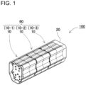
- FIG. 1 is a perspective view of a power supply device in accordance with one exemplary embodiment of the present invention.
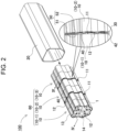
- FIG. 2 is an exploded perspective view with an enlarged side view of a main part showing of the power supply device shown in FIG. 1 with an exterior case removed.
- FIG. 3 is an exploded perspective view of a battery assembly shown in FIG. 2 .
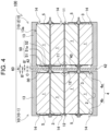
- FIG. 4 is a sectional view of the battery assembly taken on line IV-IV shown in FIG. 2 .
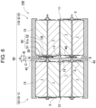
- FIG. 5 is a sectional view of the battery assembly for showing a state in which gas is ejected from a battery cell of FIG. 4 .
- FIG. 6 is a sectional view of the battery assembly for showing a state in which gas is ejected from another battery cell of FIG. 4 .
- Power supply device 100 shown in these drawings includes battery cells 1 having substantially cylindrical shapes, battery blocks 10 (10-1 to 10-3 in e.g., FIG. 1 ) including and holding battery cells 1, battery assembly 60 in which battery blocks 10 are connected to one another, and exterior case 20 accommodating battery assembly 60 therein.
- An outline of power supply device 100 will be described below, and details of the members are described later.
- battery blocks 10-1 to 10-3 are disposed and connected to one another in an axial direction of cylindrical battery cells 1.
- first block surface 11 of battery block 10-1 is away from second block surface 12 of adjacent battery block 10-2 with insulation space 30 between first block surface 11 and second block surface 12 such that first block surface 11 faces second block surface 12 across insulation space 30.
- Power supply device 100 further includes shield plate 40 disposed in insulation space 30.
- Supporter 50 supports shield plate 40.
- Supporter 50 is provided at an inner side from the outer peripheral part of each first block surface 11 of two or more battery blocks 10 and each second block surface 12 of two or more battery blocks 10 facing each other.
- Shield plate 40 thus supported by supporter 50 provided at the inner side of the block surface has outer peripheral part as free ends 42 displaceable with respect to supporter 50.
- free end 42 refers to an outer peripheral part of shield plate 40 and a part in the vicinity thereof, which is a part that is displaceable, that is, deformable, or movable, because the outer peripheral part of shield plate 40 and the vicinity thereof are not supported by, e.g., the supporter.
- the outer peripheral part of shield plate 40 is free end 42, as shown in FIG. 5 . If discharge valve 3 is opened in battery cell 1L of battery block 10-1 and gas is ejected, shield plate 40 is pressed by high-temperature and high-pressure gas, the outer peripheral part of shield plate 40 as free end 42 is displaced toward battery block 10-2 inside insulation space 30.
- This configuration provides flow path B for discharging the ejected gas in a side near battery block 10-1 in which gas is ejected. At this moment, a side near battery block 10-2 is closed by shield plate 40.
- insulation space 30 that is enough to form one flow path B in the outer peripheral parts of the interfaces of battery blocks 10-1 and 10-2 facilitates discharging gas.
- battery blocks 10 are arranged in the axial direction of battery cells 1, and reduces the size of battery blocks 10 in the arrangement direction accordingly. Since power supply device 100 has an elongated shape, power supply device 100 is suitably applied and easily attached to bicycles having various uses of applications, such as power-assisted bicycles, and sport-type bicycles. Power supply device 100 is small and inconspicuous, thus enhancing the appearance of such bicycles.
- each battery cell 1 supplying electric power to power supply device 100 includes exterior can 2 having substantially a tubular shape extending in one direction.
- Each battery cell 1 includes discharge valve 3 on one end surface of the tubular shape.
- Discharge valve 3 is configured to discharge gas in response to an increase of an internal pressure of the can.
- Each battery cell 1 further includes end electrodes 4 at both ends thereof.
- an opening of exterior can 2 made of metal, such as aluminum, is airtightly sealed with a sealing plate.
- a convex electrode is provided on the sealing plate and is used as first end electrode 4a, and the bottom of the exterior can is used as second end electrode 4b.
- a discharge port of discharge valve 3 is disposed close to the convex electrode, or on the bottom surface of the exterior can.
- a lithium-ion battery of with cylindrical battery can be used.
- a lithium-ion battery has a large capacity relative to its size and weight, and can increase the total capacity of the power supply device.
- a battery cell of the power supply device of the present invention is not particularly limited to a lithium-ion battery.
- battery cell 1 is a cylindrical battery, but the battery cell may be a rectangular battery.
- Each battery cell 1 is connected to adjacent battery cells 1 in series or in parallel to one another by welding lead plate 5 to end electrodes 4 at both ends.
- the type and the number of battery cells 1 may be appropriately adjusted depending on electric energy required. For example, ten battery cells of about 5 A/h are used in this exemplary embodiment.
- Battery block 10 includes and holds battery cells 1 arranged in parallel to one another.
- Battery assembly 60 mentioned below includes battery blocks 10 arranged in the axial direction of battery cell 1.
- Each battery block 10 includes battery holder 13 having substantially a tubular shape and holds battery cells 1.
- Battery holder 13 is produced by molding insulating materials such as plastic.
- Battery holder 13 holds exterior cans 2 of battery cells 1 parallel to one another, so that end surfaces of exterior cans 2 are flush with the same plane.
- Battery holder 13 includes insertion section 13a into which battery cell 1 is inserted and disposed in a predetermined position.
- insertion section 13a In power supply device 100 of FIG. 4 , since battery cell 1 is a cylindrical battery, insertion part 13a has a circular columnar shape.
- Battery holder 13 has first block surface 11 and second block surface 12 at both end surface thereof.
- the end surfaces of exterior cans 2 are arranged in the same plane on first block surface 11 and second block surface 12. Both ends of battery holder 13 are closed with first block surface 11 and second block surface 12.
- First block surface 11 and second block surface 12 have openings 14 from which the battery end parts are exposed, respectively. Opening 14 allows the end surfaces of battery cells 1 inserted into insertion section 13a to be exposed to the outside.
- the end surface of battery cell 1 exposed from opening 14 is fixed by welding lead plate 5 as end electrode 4. In FIGs. 1 to 3 , the lead plate is omitted for explanation.
- Battery assembly 60 includes battery blocks 10 arranged in the axial direction of battery cell 1 and connected to one another. As shown in, e.g., FIG. 1 , in this exemplary embodiment, three battery blocks 10-1 to 10-3 are connected, but the number of battery blocks 10 may be appropriately adjusted depending on electric power required. Battery assembly 60 is accommodated in exterior case 20. Exterior case 20 may further include a circuit board on which a charge and discharge circuit for controlling charging and discharging of battery cells 1, a protection circuit, and the like, are mounted.
- Insulation space 30 separates adjacent battery blocks 10 of battery assembly 60 from each other.
- first block surface 11 of battery block 10-1 and second block surface 12 of adjacent battery block 10-2 face each other across insulation space 30 and are separated from each other with insulation space 30 between first block surface 11 of battery block 10-1 and second block surface 12 of adj acent battery block 10-2.
- the width of insulation space 30, in other words, separation distance A between battery blocks 10-1 and 10-2 is about the sum of the width of one flow path B, and a thickness C of shield plate 40.
- the width of the flow path B may be appropriately adjusted depending on types of batteries, and ranges from about 3 mm to 4 mm in accordance with the present embodiment.
- battery assembly 60 including battery cells 1 with the end surfaces thereof facing insulation space 30, if discharge valve 3 of any one of, e.g., battery cells 1 of battery block 10-1 is opened, high-temperature ejected gas discharged from the discharge port is ejected toward second block surface 12 of battery block 10-2.
- the high-temperature ejected gas jetted toward the facing surface of battery cell 1 in the opposite place may cause the thermal runaway of battery cell 1.
- power supply device 100 of FIG. 3 to FIG. 6 includes shield plate 40 disposed substantially in the middle of insulation space 30. If gas is discharged from any one of battery cells 1, shield plate 40 prevents the gas from being ejected into facing another battery block 10.
- the size of shield plate 40 may have an arbitrary size as long as gas ejected into facing battery block 10 can be avoided.
- the size and shape of the shield plate are substantially identical to those of first block surface 11 and second block surface 12 of battery block 10.
- Shield plate 40 may be made of a heat-resistant plate with a heat-resistant temperature, that is, a melting point, which is not melted by the ejected gas discharged from discharge valve 3. Shield plate 40 may have flexibility.
- shield plate 40 may be made of carbon fibers, silica fibers, glass fibers, or flexible materials including these fibers impregnated with resin. When gas is ejected, shield plate 40 with flexibility deforms with a pressure of high-temperature and high-pressure gas, and easily form the below-mentioned flow path B for discharging gas accordingly.
- Shield plate 40 shown in Fig. 4 is disposed parallel to first block surface 11 and second block surface 12 of the adjacent battery blocks. Then, flow path B' with a width which is about 1/2 of the width of flow path B is formed on each of both sides of shield plate 40.
- the separation distance A between battery blocks 10-1 and 10-2 is determined to be about the sum of the width of two flow paths B' (that is, flow path B) and the thickness C of shield plate 40.
- Supporter 50 supports shield plate 40.
- FIGs. 3 and 4 show an example of supporter 50.
- supporter 50 is provided at the inner side than respective outer peripheral parts of first block surface 11 and second block surface 12 of battery blocks 10 facing each other.
- the number of supporters 50 may be appropriately adjusted depending on the size of shield plate 40. For example, in Embodiment 1, four first supporters 51 in total, two in the vertical direction and two in the horizontal direction of first block surface 11 of battery block 10, are provided. Similarly, four second supporters 52 are provided at places corresponding to first supporters 51 on second block surface 12.
- First supporter 51 and second supporter 52 may have arbitrary shapes as long as first supporter 51 and second supporter 52 may be connected to each other.
- first supporter 51 is convex
- second supporter 52 is a concave that can be connected to first supporter 51.
- First supporter 51 and second supporter 52 are connected to each other such that shield plate 40 are interposed between the supporters supporting shield plate 40.
- Shield-plate opening 41 may be provided in shield plate 40 at positions corresponding to first supporter 51 and second supporter 52.
- the size of shield-plate opening 41 is about a size through which, for example, distal end part 51a of first supporter 51 of FIG. 3 can penetrate.
- Distal end part 51a of first supporter 51 penetrating through shield-plate opening 41 is inserted into second supporter 52 and connected to second supporter 52 such that shield plate 40 is sandwiched from both sides thereof by first supporter 51 and second supporter 52.
- first supporter 51 and second supporter 52 Distal end part 51a of first supporter 51 penetrating through shield-plate opening 41 is inserted into second supporter 52 and connected to second supporter 52 such that shield plate 40 is sandwiched from both sides thereof by first supporter 51 and second supporter 52.
- the periphery of the middle of shield plate 40 is fixed and supported.
- the supporter and the shield plate of this exemplary embodiment are not limited to the above-mentioned example.
- the first supporter may be concave, and the second supporter may be convex.
- shield plate 40 does not necessarily have shield-plate opening 41 therein, and the first supporter and the second supporter may be convex, and support by sandwiching shield plate 40 from the both sides.
- Supporter 50 thus provided in the inner side than the outer peripheral parts of first block surface 11 and second block surface 12 does not support the outer peripheral part of shield plate 40 and the vicinity thereof while supporting the periphery of the middle part of shield plate 40.
- the peripheral part of shield plate 40 and the vicinity thereof are free end 42.
- heat-resistant sheet 920 is disposed in the middle part of the block surfaces of the facing battery blocks 910. Since peripheral parts of heat-resistant sheet 920 are fixed, exhaust chambers 930 and 930 are formed on both sides of heat-resistant sheet 920 to form two flow paths B for discharging gas.
- separation distance A" between the block surfaces of battery blocks 910 are about the sum of the widths of the two flow paths B and the thickness C of heat-resistant sheet 920. That is, two flow paths B causes the separation distance A" between the block surfaces of battery block 910 to be wider than separation distance A by one width of flow path B in power supply device 100 of Embodiment 1.
- the outer peripheral part of shield plate 40 is displaceable free end 42. Therefore, if gas is ejected from any one of battery cells 1 of battery block 10, the outer peripheral part of shield plate 40 deforms toward another battery block 10 and forms path B for discharging gas.
- exhaust chambers 930 and 930 are not provided on both sides of heat-resistant sheet 920 as conventionally, one insulation space 30 are shared by battery blocks 10 on both sides, and allows battery blocks 10 to have a small size in the arranging direction.
- a power supply devices being thinner and smaller than conventional device is provided while securing safety, and the power supply device is applicable to various types of bicycles and the like.
- shield plate 40 is made of carbon fibers, silica fibers, glass fibers, or flexible materials including these fibers impregnated with resin, and the inside of the outer peripheral part of shield plate 40 is fixed by supporter 50.
- the power supply device of this disclosure is not limited to the above-mentioned embodiment.
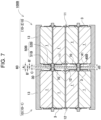
- FIG. 7 is a sectional view of a part of power supply device 100B in accordance with Exemplary Embodiment 2.
- components identical to those of the device according to Embodiment 1 are denoted by the same reference numerals, and the description thereof will be appropriately omitted.
- Power supply device 100B includes shield plate 40B having rigidity to some extent instead of shield plate 40 having flexibility of Embodiment 1.
- shield plate 40B For materials constituting shield plate 40B, previously known materials having thermal resistance can be appropriately used.
- the enhanced rigidity of shield plate 40B enhances durability of power supply device 100B.
- shield plate 40B Since this shield plate 40B has high rigidity, entire shield plate 40B is movable inside insulation space 30 to form flow path B, instead of deforming the outer peripheral part of shield plate 40B to form flow path B for discharging gas. That is, instead deforming a part of shield plate 40B, by moving shield plate 40B per se provides displacement of the outer peripheral part of the shield plate and secures a wide gas discharge flow path.
- shield plate 40B is movable on the outer peripheral surface of supporter 50B in which first supporter 51B and second supporter 52B are connected to each other in direction d3 of arrow 13 denoted (the left and right direction in Fig. 7 ).
- shield plate 40B of FIG. 8 moves toward battery block 10-2, and forms flow path B near battery block 10-1 for discharging gas.
- Power supply device 100B may further include auxiliary support parts 70 configured to melt with heat.
- Auxiliary support part 70 restricts movement of shield plate 40B at normal time in which shield plate 40B is movable inside insulation space 30. This configuration avoids contact of shield plate 40B with the block surfaces due to outer vibration at normal time. This prevents noises from occurring due to contact between shield plate 40B and one of the block surfaces.
- auxiliary support part 70 is provided between first block surface 11 of battery block 10-1 and second block surface 12 of battery block 10-2, and around supporters 50B.
- Auxiliary support part 70 may be made of, e.g., resin.
- Shield plate 40B is safely held inside insulation space 30 by supporter 50B and auxiliary support part 70.
- auxiliary support part 70 melts with heat, smooth discharge of gas can be achieved without preventing movement of shield plate 40B or discharge of gas.
- the power supply device in accordance with Embodiment 2 secures a gas discharge path widely over the entire part by moving not a part but an entire part of shield plate 40B. That is, it is possible to avoid the case where a gas discharge path is partly narrowed, so that advantages that gas can be discharged more smoothly can be achieved.
- auxiliary support part 70 melting with heat is provided around supporter 50B, but the present invention does not limit the position of auxiliary support part 70 to this configuration.
- an auxiliary supporter may be further provided in a place that is different from that of the supporter.
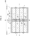
- auxiliary support part 70B may be disposed between supporters 50B.
- auxiliary support part 70B may be increased and secure a wide contact area for holding shield plate 40B while holding shield plate 40B stably.
- auxiliary support parts 70B may be provided at plural positions. As a result, the number of sites holding the shield plate 40B by auxiliary support parts 70B is increased, and the vibration and rattling of the shield plate 40B can be suppressed more stably.
- auxiliary support part 70B may be added.
- auxiliary support part 70B is made of material configured to instantly melt with high-temperature and high-pressure gas, so that auxiliary support part 70B does not prevent gas discharge at the time of gas release.
- the power supply device in accordance with Embodiment 2 has a configuration in which shield plate 40B has shield-plate opening 41 therein to allow supporter 50B to be inserted into shield-plate opening 4.
- the configuration is not limited to this configuration and the supporter may be omitted and shield plate 40B may be held by auxiliary support parts 70B. This configuration provides advantage that holding structure of shield plate 40B can be further simplified and can configured at lower cost.
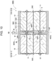
- FIG. 10 is a sectional view of a part of power supply device 100C in accordance with Exemplary Embodiment 3.
- FIG. 10 components identical those of the device of Embodiment 1 are denoted by the same reference numerals, and detailed description thereof will be appropriately omitted.
- supporter 50C further includes third supporter 53C in the middle part of first block surface 11 and second block surface 12 of each battery block 10.
- shield plate 40C in accordance with Embodiment 3 has some rigidity.
- the space for gas discharge is variable.
- the middle part of shield plate 40C is tiltably sandwiched by third supporters 53C provided in first block surface 11 and second block surface 12, respectively.
- Third supporter 53C may appropriately have any configuration supporting the shield plate 40 C tiltably.
- third supporter 53C has a trigonal prismatic shape and linearly contact shield plate 40C to support shield plate 40C so that shield plate 40C may tilt about a rotating axis denoted by the black point in FIG. 10 .
- the apex of the trigonal prismatic shape of third supporter 53C may be preferably curved rather than sharply angled.
- a boss may protrude from the end surface of the shield plate and a shaft hole for receiving the boss may be formed in third supporter 53C so as to allow third supporter 53C to be tiltable.
- third supporter 53C may have a conical shape, the center of the shield plate 40C may be recessed and supported with respect to a point so as to allow the entire peripheral circumference of the shield plate of 360°to incline.
- the power supply device may preferably further include a positioning mechanism in order to smoothly tilt shield plate 40C.
- a positioning mechanism in order to smoothly tilt shield plate 40C.
- shield-plate opening 41 is provided in the inner side of the outer peripheral part of shield plate 40C, and first supporter 51C and second supporter 52C are inserted into shield-plate opening 41 to position the shield plate.
- shield plate 40C to be movable about third supporter 53C in a rotational direction denoted by arrow d4 shown in FIG. 10 .
- end part 42Ca of shield plate 40C near battery cell 1L moves toward battery block 10-2 due to the pressure of high-temperature and high-pressure gas, and forms flow path B for discharging gas.
- end part 42Cb at the opposite side of shield plate 40C moves toward battery cell 1L in which gas is ejected so as to close insulation space 30.
- flow path B for discharging gas can be formed in the side near battery cell 1L in which gas is ejected, so that an ejected gas is discharged in the shortest path.
- the shield plate is not fixed but is floated.
- the volume of the gas discharge flow path demarcated by the shield plate may be variable, and the flow path may be widened on the side where gas is discharged. That is, the position of the shield plate is variable in a space in which a gas discharge amount flow path provided between the facing battery cells, so that two gas discharge paths may be provided by partitioning the common space.
- a gas discharge flow path that is merely used has a small size when not used reduces the size of the power supply device, when gas is discharged, a wide gas discharge flow path is secured on the corresponding side, so that similar safety can be secured.
- the device since the possibility that gas is discharged is extremely low, assuming that the gas is one of a lot of secondary battery cells even if gas is discharged, the device may reduce the gas discharge flow path, which is used to be uniformly provided for the secondary battery cells. Further, when the gas discharge path is used, a gas discharge flow path at the non-used side is used. Thereby, the same flow path volume is secured as conventionally and the advantage of not reducing safety is achieved.
- a power supply device of the present invention is usable as power supplies for powering electric vehicles such as electric bicycles, electric scooters, electric carts, and electric vehicles, and as power supplies for household and factory power storage devices.
Landscapes
- Chemical & Material Sciences (AREA)
- Chemical Kinetics & Catalysis (AREA)
- Electrochemistry (AREA)
- General Chemical & Material Sciences (AREA)
- Engineering & Computer Science (AREA)
- Manufacturing & Machinery (AREA)
- Battery Mounting, Suspending (AREA)
Abstract
Description
- The present invention relates to a power supply device.
- Power supply devices such as battery packs are used as power supplies for power-assisted bicycles, electric motorcycles, power tools, electric cleaners, and the like. In a power supply device, a lot of secondary battery cells are arranged and connected in series or in parallel to increase output and capacity. For example,
power supply device 90 ofPTL 1 shown inFIG. 12 includesbattery units 92 each includingsecondary battery cells 91 arranged in parallel to each other.Battery units 92 are coupled to each other in a position in which end surfaces ofsecondary battery cells 91 face each other, and are accommodated in a housing. - Each
secondary battery cell 91 includes a safety valve. When a pressure in an exterior can becomes high, the high pressure is detected, and the safety valve is opened to discharge high-pressure and high-temperature gas inside the exterior can to the outside of the cell. Sincepower supply device 90 ofFIG. 12 includessecondary battery cells 91 that are disposed such that the end surfaces ofsecondary battery cells 91 face each other, when high-temperature gas is ejected from any one ofsecondary battery cells 91, othersecondary battery cell 91 adj acent to any one ofsecondary battery cells 91 and being disposed with the end surfaces facing the any one ofsecondary battery cells 91 is irradiated with the high-temperature gas and damaged. - Then, in
power supply device 90 ofFIG. 12 , heat-resistant sheet 93 is disposed betweenbattery units 92 facing each other, andexhaust chambers resistant sheet 93. Furthermore, outerperipheral frame parts resistant sheet 93. Outerperipheral frame parts resistant sheet 93. Outerperipheral frame parts resistant sheet 93 and between facingbattery units 92, and the outer peripheral part of heat-resistant sheet 93 is supported and heat-resistant sheet 93 is held betweenbattery units 92. - In
power supply device 90 ofFIG. 12 , in a case of increasingsecondary battery cells 91,secondary battery cells 91 may be stacked in direction d1 which is a longitudinal direction inFIG. 12 . On the other hand, for example, like in a case where a power supply device is used for a power-assisted bicycle, the power supply device may require an elongated long housing due to a limit by a place in which the power supply device is disposed. In this case, while the number of stacks in direction d1 inFIG. 12 in each battery unit is decreased, andbattery units 92 is stacked in direction d2 that is perpendicular to direction d1. In such a configuration, heat-resistant sheet 93 andexhaust chambers - However, when the number of couplings of the battery units in direction d2 is increased in each interface of the battery units, a heat-resistant sheet and exhaust chambers provided on both sides thereof are needed, the size of the housing in the d2 direction was likely to increase cumulatively.
- PTL 1: International Publication No.
WO2019/065169 - One object of the present invention is to provide a power supply device including secondary battery cells such that end surfaces of the secondary battery cells face each other which secures safety and has a small size.
- A power supply device according to an aspect of the present invention includes: a plurality of battery cells including exterior cans and discharge valves, each of the plurality of battery cells including a corresponding one of the exterior cans and a corresponding one of the discharge valves, the corresponding one of the exterior cans having a tubular shape extending in one direction, the corresponding one of the discharge valves being provided at an end surface of the tubular shape of the corresponding one of the exterior cans, the corresponding one of the discharge valves being configured to discharge gas in response to an increase of an internal pressure of the corresponding one of the exterior cases; a plurality of battery blocks holding the plurality of battery cells, each of the plurality of battery blocks holding two or more battery cells out of the plurality of battery cells such that the exterior cans are parallel to one another and end surfaces of the exterior cans of the two or more battery cells are flush with a plane; a shield plate disposed in an insulation space between adjacent battery blocks out of the plurality of the battery blocks, a block surface of one of the adjacent battery blocks at which end surfaces of the exterior cans of the two or more battery cells faces, across the insulation space, a block surface of another of the adjacent battery blocks at which end surfaces of the exterior cans of the two or more battery cells; and a supporter supporting the shield plate, the supporter being provided on an inner side of outer peripheral parts of the block surfaces of the plurality of battery blocks facing each other. The shield plate supported by the supporter includes an outer peripheral part that is a free end displaceable with respect to the supporter.
- In the above-mentioned configuration, the shield plate has a displaceable free end. Even if the discharge valve is opened and gas is ejected in any one of battery cells, high-temperature and high-pressure gas presses the shield plate, and the shield plate is displaced toward the facing battery block in the insulation space, thereby securing a wide flow path for discharging the ejected gas. Thus, although an insulation space is not previously provided on both sides of the shield plate, an insulation space can be shared by battery blocks at both sides. The size of the entire power supply device is reduced accordingly.
-
-
FIG. 1 is a perspective view of a power supply device in accordance with an exemplary embodiment of the present invention. -
FIG. 2 is an exploded perspective view with an enlarged side view of a main part of the power supply device ofFIG. 1 with an exterior case removed. -
FIG. 3 is an exploded perspective view of a battery assembly shown inFIG. 2 . -
FIG. 4 is a sectional view of the battery assembly taken on line IV-IV shown inFIG. 2 . -
FIG. 5 is a sectional view of the battery assembly shown inFIG. 4 for showing a state in which gas is ejected from the battery cell. -
FIG. 6 is a sectional view of another battery assembly shown inFIG. 4 for showing a state in which gas is ejected from the battery cell. -
FIG. 7 is a partial sectional view of a power supply device in accordance withExemplary Embodiment 2. -
FIG. 8 is a sectional view of a battery cell shown inFIG. 7 for showing a state in which gas is ejected from the battery cell. -
FIG. 9 is a partial sectional view of a power supply device in accordance with a modified example. -
FIG. 10 is a partial sectional view of a power supply device in accordance withExemplary Embodiment 3. -
FIG. 11 is a sectional view of a battery cell shown inFIG. 10 for showing a state in which gas is ejected from the battery cell. -
FIG. 12 is a sectional view of a conventional power supply device. -
FIG. 13 is a perspective view of another conventional power supply device. -
FIG. 14 is a sectional view of the power supply device taken on line XIV-XIV shown inFIG. 13 . - A power supply device of one embodiment of the present invention may include the following configuration in addition to the above-mentioned configuration. In the power supply device, the supporter may include: a first supporter provided on a first block surface which is the block surface of the one of the adjacent battery blocks facing each other; and a second supporter provided on a second block surface which is the block surface of the another of the adjacent battery blocks at a position corresponding to the first supporter, the second supporter being connected to the first supporter through the shield plate.
- In the power supply device, the shield plate may have a shield-plate opening therein at a position corresponding to the supporter, and the supporter may be inserted into the shield-plate opening.
- In the power supply device, the supporter may be one of a plurality of supporters provided on end surfaces of the plurality of battery blocks.
- In the power supply device, the supporter may be provided at a middle part of each end surface of the battery block, and the shield plate may be movable in a rotation direction about the supporter. In this configuration, the end part of the shield plate near a battery cell in which gas is ejected moves away from the battery cell, and a flow path for discharging gas is formed. On the other hand, the end part at the opposite side of the shield plate is movable toward the battery cell in which gas is ejected so as to close the insulation space. As a result, a flow path for discharging gas is formed toward a battery cell at which gas is ejected, so that ejected gas can be discharged in the shortest path.
- The power supply device may further include a plurality of auxiliary support parts provided between the block surfaces of the adj acent battery blocks facing each other, the plurality of auxiliary support parts being configured to melt with heat. In this configuration, the shield plate is held in the insulation space by the supporter and the auxiliary support part. On the other hand, if high-temperature and high-pressure gas is ejected from any one of the secondary battery cells, the auxiliary support parts are melted with heat, gas is smoothly discharged without preventing displacement of the shield plate or discharge of gas.
- In the power supply device, the shield plate may be made of carbon fibers, silica fibers, glass fibers, or flexible materials, the flexible materials including carbon fibers, silica fibers, or glass fibers and impregnated with resin. In this configuration, when gas is ejected, a flexible shield plate may warp, and a flow path for discharging gas can be formed easily.
- Furthermore, the shield plate may be made of carbon fibers, silica fibers, glass fibers, or flexible materials, the flexible materials including carbon fibers, silica fibers, or glass fibers and impregnated with resin. In this configuration, the rigidity of the shield plate can be enhanced.
- Hereinafter, exemplary embodiments of the present invention are described with reference to the drawings. However, the exemplary embodiments described below are deemed to be merely illustrative of a configuration for giving a concrete form to the technical idea of the present invention, and therefore, the present invention is not limited to the following. Furthermore, members set forth in claims are never limited to members in the exemplary embodiments. In particular, a size, a material, a shape, relative positioning, or the like, of the component members described in the exemplary embodiments is not aimed at limiting the scope of the present invention only thereto unless otherwise described but merely illustrative. Note here that a size, a positional relationship, or the like, of the members in the respective drawings may be exaggerated for clarifying the description. Furthermore, in the following description, the same or similar members are represented by the same names and reference symbols, and the detailed description thereof is appropriately omitted. As for each component of the present invention, one member may serve as a plurality of components by forming the plurality of components with the same member. On the contrary, a function of one member may be shared by the plurality of members. Furthermore, details described in one exemplary embodiment may be applied to the other embodiments or the like.
- Examples in which the power supply device mentioned below is mainly applied to the power supplies for driving electric vehicles such as electric bicycles, electric scooters, electric carts, and electric vehicles that run only on motors, are described. Note here that the power supply device of the present invention may be used in hybrid vehicles that run on both engines and motors, or in applications where high power is required other than electric vehicles, for example, power storage devices for household or factory use.
-
FIGs. 1 to 6 show a power supply device in accordance withExemplary Embodiment 1.FIG. 1 is a perspective view of a power supply device in accordance with one exemplary embodiment of the present invention.FIG. 2 is an exploded perspective view with an enlarged side view of a main part showing of the power supply device shown inFIG. 1 with an exterior case removed.FIG. 3 is an exploded perspective view of a battery assembly shown inFIG. 2 .FIG. 4 is a sectional view of the battery assembly taken on line IV-IV shown inFIG. 2 .FIG. 5 is a sectional view of the battery assembly for showing a state in which gas is ejected from a battery cell ofFIG. 4 .FIG. 6 is a sectional view of the battery assembly for showing a state in which gas is ejected from another battery cell ofFIG. 4 . -
Power supply device 100 shown in these drawings includesbattery cells 1 having substantially cylindrical shapes, battery blocks 10 (10-1 to 10-3 in e.g.,FIG. 1 ) including and holdingbattery cells 1,battery assembly 60 in which battery blocks 10 are connected to one another, andexterior case 20accommodating battery assembly 60 therein. An outline ofpower supply device 100 will be described below, and details of the members are described later. - In
power supply device 100 shown inFIG. 2 , battery blocks 10-1 to 10-3 are disposed and connected to one another in an axial direction ofcylindrical battery cells 1. For example,first block surface 11 of battery block 10-1 is away fromsecond block surface 12 of adjacent battery block 10-2 withinsulation space 30 betweenfirst block surface 11 andsecond block surface 12 such thatfirst block surface 11 facessecond block surface 12 acrossinsulation space 30. -
Power supply device 100 further includesshield plate 40 disposed ininsulation space 30.Supporter 50 supportsshield plate 40.Supporter 50 is provided at an inner side from the outer peripheral part of eachfirst block surface 11 of two or more battery blocks 10 and eachsecond block surface 12 of two or more battery blocks 10 facing each other.Shield plate 40 thus supported bysupporter 50 provided at the inner side of the block surface has outer peripheral part asfree ends 42 displaceable with respect tosupporter 50. - Herein, "
free end 42" refers to an outer peripheral part ofshield plate 40 and a part in the vicinity thereof, which is a part that is displaceable, that is, deformable, or movable, because the outer peripheral part ofshield plate 40 and the vicinity thereof are not supported by, e.g., the supporter. - The outer peripheral part of
shield plate 40 isfree end 42, as shown inFIG. 5 . Ifdischarge valve 3 is opened inbattery cell 1L of battery block 10-1 and gas is ejected,shield plate 40 is pressed by high-temperature and high-pressure gas, the outer peripheral part ofshield plate 40 asfree end 42 is displaced toward battery block 10-2 insideinsulation space 30. This configuration provides flow path B for discharging the ejected gas in a side near battery block 10-1 in which gas is ejected. At this moment, a side near battery block 10-2 is closed byshield plate 40. As a result,insulation space 30 that is enough to form one flow path B in the outer peripheral parts of the interfaces of battery blocks 10-1 and 10-2 facilitates discharging gas. - Similarly, when gas is ejected from
battery cell 1R of battery block 10-2, as shown inFIG. 6 , free ends 42 ofshield plate 40 are displaced toward battery block 10-1, and flow path B is formed in a side near battery block 10-2. Unlike conventionalpower supply device 90 shown inFIG. 12 , even if twowide exhaust chambers 94 may not be provided at both sides of heat-resistant sheet 93, oneinsulation space 30 is thus shared by battery blocks 10-1 and 10-2 at both ends of heat-resistant sheet 93. - Thus, in
power supply device 100 in accordance with the present embodiment, battery blocks 10 are arranged in the axial direction ofbattery cells 1, and reduces the size of battery blocks 10 in the arrangement direction accordingly. Sincepower supply device 100 has an elongated shape,power supply device 100 is suitably applied and easily attached to bicycles having various uses of applications, such as power-assisted bicycles, and sport-type bicycles.Power supply device 100 is small and inconspicuous, thus enhancing the appearance of such bicycles. - As shown in
Fig. 4 , eachbattery cell 1 supplying electric power topower supply device 100 includes exterior can 2 having substantially a tubular shape extending in one direction. Eachbattery cell 1 includesdischarge valve 3 on one end surface of the tubular shape.Discharge valve 3 is configured to discharge gas in response to an increase of an internal pressure of the can. Eachbattery cell 1 further includesend electrodes 4 at both ends thereof. In thisbattery cell 1, an opening of exterior can 2 made of metal, such as aluminum, is airtightly sealed with a sealing plate. A convex electrode is provided on the sealing plate and is used asfirst end electrode 4a, and the bottom of the exterior can is used assecond end electrode 4b. A discharge port ofdischarge valve 3 is disposed close to the convex electrode, or on the bottom surface of the exterior can. - For
battery cell 1, for example, a lithium-ion battery of with cylindrical battery can be used. A lithium-ion battery has a large capacity relative to its size and weight, and can increase the total capacity of the power supply device. However, a battery cell of the power supply device of the present invention is not particularly limited to a lithium-ion battery. For a battery cell, other chargeable secondary batteries can be used. Furthermore, inpower supply device 100 shown in, for example,FIG. 4 ,battery cell 1 is a cylindrical battery, but the battery cell may be a rectangular battery. Eachbattery cell 1 is connected toadjacent battery cells 1 in series or in parallel to one another by weldinglead plate 5 to endelectrodes 4 at both ends. The type and the number ofbattery cells 1 may be appropriately adjusted depending on electric energy required. For example, ten battery cells of about 5 A/h are used in this exemplary embodiment. -
Battery block 10 includes and holdsbattery cells 1 arranged in parallel to one another.Battery assembly 60 mentioned below includes battery blocks 10 arranged in the axial direction ofbattery cell 1. - Each
battery block 10 includesbattery holder 13 having substantially a tubular shape and holdsbattery cells 1.Battery holder 13 is produced by molding insulating materials such as plastic.Battery holder 13 holdsexterior cans 2 ofbattery cells 1 parallel to one another, so that end surfaces ofexterior cans 2 are flush with the same plane. -
Battery holder 13 includesinsertion section 13a into whichbattery cell 1 is inserted and disposed in a predetermined position. Inpower supply device 100 ofFIG. 4 , sincebattery cell 1 is a cylindrical battery,insertion part 13a has a circular columnar shape. -
Battery holder 13 hasfirst block surface 11 andsecond block surface 12 at both end surface thereof. The end surfaces ofexterior cans 2 are arranged in the same plane onfirst block surface 11 andsecond block surface 12. Both ends ofbattery holder 13 are closed withfirst block surface 11 andsecond block surface 12.First block surface 11 andsecond block surface 12 haveopenings 14 from which the battery end parts are exposed, respectively.Opening 14 allows the end surfaces ofbattery cells 1 inserted intoinsertion section 13a to be exposed to the outside. The end surface ofbattery cell 1 exposed from opening 14 is fixed by weldinglead plate 5 asend electrode 4. InFIGs. 1 to 3 , the lead plate is omitted for explanation. -
Battery assembly 60 includes battery blocks 10 arranged in the axial direction ofbattery cell 1 and connected to one another. As shown in, e.g.,FIG. 1 , in this exemplary embodiment, three battery blocks 10-1 to 10-3 are connected, but the number of battery blocks 10 may be appropriately adjusted depending on electric power required.Battery assembly 60 is accommodated inexterior case 20.Exterior case 20 may further include a circuit board on which a charge and discharge circuit for controlling charging and discharging ofbattery cells 1, a protection circuit, and the like, are mounted. -
Insulation space 30 separates adjacent battery blocks 10 ofbattery assembly 60 from each other. For example, as shown inFIG. 5 ,first block surface 11 of battery block 10-1 andsecond block surface 12 of adjacent battery block 10-2 face each other acrossinsulation space 30 and are separated from each other withinsulation space 30 betweenfirst block surface 11 of battery block 10-1 andsecond block surface 12 of adj acent battery block 10-2. The width ofinsulation space 30, in other words, separation distance A between battery blocks 10-1 and 10-2 is about the sum of the width of one flow path B, and a thickness C ofshield plate 40. The width of the flow path B may be appropriately adjusted depending on types of batteries, and ranges from about 3 mm to 4 mm in accordance with the present embodiment. - In
battery assembly 60 includingbattery cells 1 with the end surfaces thereof facinginsulation space 30, ifdischarge valve 3 of any one of, e.g.,battery cells 1 of battery block 10-1 is opened, high-temperature ejected gas discharged from the discharge port is ejected towardsecond block surface 12 of battery block 10-2. The high-temperature ejected gas jetted toward the facing surface ofbattery cell 1 in the opposite place may cause the thermal runaway ofbattery cell 1. - Thus,
power supply device 100 ofFIG. 3 to FIG. 6 includesshield plate 40 disposed substantially in the middle ofinsulation space 30. If gas is discharged from any one ofbattery cells 1,shield plate 40 prevents the gas from being ejected into facing anotherbattery block 10. The size ofshield plate 40 may have an arbitrary size as long as gas ejected into facingbattery block 10 can be avoided. In this exemplary embodiment, the size and shape of the shield plate are substantially identical to those offirst block surface 11 andsecond block surface 12 ofbattery block 10. -
Shield plate 40 may be made of a heat-resistant plate with a heat-resistant temperature, that is, a melting point, which is not melted by the ejected gas discharged fromdischarge valve 3.Shield plate 40 may have flexibility. For example, inEmbodiment 1,shield plate 40 may be made of carbon fibers, silica fibers, glass fibers, or flexible materials including these fibers impregnated with resin. When gas is ejected,shield plate 40 with flexibility deforms with a pressure of high-temperature and high-pressure gas, and easily form the below-mentioned flow path B for discharging gas accordingly. -
Shield plate 40 shown inFig. 4 is disposed parallel tofirst block surface 11 andsecond block surface 12 of the adjacent battery blocks. Then, flow path B' with a width which is about 1/2 of the width of flow path B is formed on each of both sides ofshield plate 40. Thus, the separation distance A between battery blocks 10-1 and 10-2 is determined to be about the sum of the width of two flow paths B' (that is, flow path B) and the thickness C ofshield plate 40. When gas is ejected frombattery cell 1 of oneblock 10,shield plate 40 thus disposed in this way has the peripheral part ofshield plate 40 deform toward theother battery block 10 so as to form flow path B shown inFIGs. 5 and6 . -
Supporter 50 supportsshield plate 40.FIGs. 3 and4 show an example ofsupporter 50. As shown in these figures,supporter 50 is provided at the inner side than respective outer peripheral parts offirst block surface 11 andsecond block surface 12 of battery blocks 10 facing each other. The number ofsupporters 50 may be appropriately adjusted depending on the size ofshield plate 40. For example, inEmbodiment 1, fourfirst supporters 51 in total, two in the vertical direction and two in the horizontal direction offirst block surface 11 ofbattery block 10, are provided. Similarly, foursecond supporters 52 are provided at places corresponding tofirst supporters 51 onsecond block surface 12. -
First supporter 51 andsecond supporter 52 may have arbitrary shapes as long asfirst supporter 51 andsecond supporter 52 may be connected to each other. In the present embodiment,first supporter 51 is convex, andsecond supporter 52 is a concave that can be connected tofirst supporter 51.First supporter 51 andsecond supporter 52 are connected to each other such thatshield plate 40 are interposed between the supporters supportingshield plate 40. Shield-plate opening 41 may be provided inshield plate 40 at positions corresponding tofirst supporter 51 andsecond supporter 52. The size of shield-plate opening 41 is about a size through which, for example,distal end part 51a offirst supporter 51 ofFIG. 3 can penetrate.Distal end part 51a offirst supporter 51 penetrating through shield-plate opening 41 is inserted intosecond supporter 52 and connected tosecond supporter 52 such thatshield plate 40 is sandwiched from both sides thereof byfirst supporter 51 andsecond supporter 52. Thus, the periphery of the middle ofshield plate 40 is fixed and supported. - The supporter and the shield plate of this exemplary embodiment are not limited to the above-mentioned example. For example, the first supporter may be concave, and the second supporter may be convex. Furthermore,
shield plate 40 does not necessarily have shield-plate opening 41 therein, and the first supporter and the second supporter may be convex, and support by sandwichingshield plate 40 from the both sides. -
Supporter 50 thus provided in the inner side than the outer peripheral parts offirst block surface 11 andsecond block surface 12 does not support the outer peripheral part ofshield plate 40 and the vicinity thereof while supporting the periphery of the middle part ofshield plate 40. In other words, the peripheral part ofshield plate 40 and the vicinity thereof arefree end 42. Thus, as shown inFIG. 5 , whendischarge valve 3 is opened inbattery cell 1L of battery block 10-1 and gas is ejected, high-temperature and high-pressure gas pressesshield plate 40 includingfree end 42, andfree end 42 ofshield plate 40 is configured to deform ininsulation space 30 toward the facing battery block 10-2. This configuration secures flow path B for discharging the ejected gas. - On the other hand, in conventional
power supply device 900 shown inFIG. 13 or14 including twobattery blocks resistant sheet 920 is fixed. In the convex part protruding from the peripheral part of the block surface of the battery block, heat-resistant sheet 920 is sandwiched from the both sides and fixed. Inpower supply device 900, since interfaces of facing battery blocks 910 are closed,discharge port 940 of gas is partially provided. However, the outer peripheral part of heat-resistant sheet 920 which is fixed, unlikeEmbodiment 1, prevents the peripheral part of heat-resistant sheet 920 from being displaced and forming path B. Therefore, the conventional device necessarily formsexhaust chambers resistant sheet 920. - Specifically, as shown in
FIG. 14 , heat-resistant sheet 920 is disposed in the middle part of the block surfaces of the facing battery blocks 910. Since peripheral parts of heat-resistant sheet 920 are fixed,exhaust chambers resistant sheet 920 to form two flow paths B for discharging gas. - In the case that the thickness of heat-
resistant sheet 920 is the thickness C that is the same as the thickness ofshield plate 40, separation distance A" between the block surfaces of battery blocks 910 are about the sum of the widths of the two flow paths B and the thickness C of heat-resistant sheet 920. That is, two flow paths B causes the separation distance A" between the block surfaces ofbattery block 910 to be wider than separation distance A by one width of flow path B inpower supply device 100 ofEmbodiment 1. - On the contrary, in
power supply device 100 ofEmbodiment 1, the outer peripheral part ofshield plate 40 is displaceablefree end 42. Therefore, if gas is ejected from any one ofbattery cells 1 ofbattery block 10, the outer peripheral part ofshield plate 40 deforms toward anotherbattery block 10 and forms path B for discharging gas. Thus, even ifexhaust chambers resistant sheet 920 as conventionally, oneinsulation space 30 are shared bybattery blocks 10 on both sides, and allows battery blocks 10 to have a small size in the arranging direction. As a result, a power supply devices being thinner and smaller than conventional device is provided while securing safety, and the power supply device is applicable to various types of bicycles and the like. - In the device according to
Embodiment 1,shield plate 40 is made of carbon fibers, silica fibers, glass fibers, or flexible materials including these fibers impregnated with resin, and the inside of the outer peripheral part ofshield plate 40 is fixed bysupporter 50. However, the power supply device of this disclosure is not limited to the above-mentioned embodiment.FIG. 7 is a sectional view of a part ofpower supply device 100B in accordance withExemplary Embodiment 2. InFIG. 7 , components identical to those of the device according toEmbodiment 1 are denoted by the same reference numerals, and the description thereof will be appropriately omitted. -
Power supply device 100B includesshield plate 40B having rigidity to some extent instead ofshield plate 40 having flexibility ofEmbodiment 1. For materials constitutingshield plate 40B, previously known materials having thermal resistance can be appropriately used. Furthermore, a metal plate, a metal plate with an insulating material attached to a front surface and a rear surface of the metal plate, a metal plate with both surfaces thereof insulation-treated, a mica sheet, a fire-retardant fiber, or the like, can be used. The enhanced rigidity ofshield plate 40B enhances durability ofpower supply device 100B. - Since this
shield plate 40B has high rigidity,entire shield plate 40B is movableinside insulation space 30 to form flow path B, instead of deforming the outer peripheral part ofshield plate 40B to form flow path B for discharging gas. That is, instead deforming a part ofshield plate 40B, by movingshield plate 40B per se provides displacement of the outer peripheral part of the shield plate and secures a wide gas discharge flow path. - Specifically, instead of the embodiment in which the inside of the outer peripheral part of
shield plate 40 is fixed bysupporter 50 as inEmbodiment 1, as inFIG. 7 ,shield plate 40B is movable on the outer peripheral surface ofsupporter 50B in whichfirst supporter 51B andsecond supporter 52B are connected to each other in direction d3 ofarrow 13 denoted (the left and right direction inFig. 7 ). - If gas is ejected from
battery cell 1L of battery block 10-1,shield plate 40B ofFIG. 8 moves toward battery block 10-2, and forms flow path B near battery block 10-1 for discharging gas. -
Power supply device 100B may further includeauxiliary support parts 70 configured to melt with heat.Auxiliary support part 70 restricts movement ofshield plate 40B at normal time in whichshield plate 40B is movableinside insulation space 30. This configuration avoids contact ofshield plate 40B with the block surfaces due to outer vibration at normal time. This prevents noises from occurring due to contact betweenshield plate 40B and one of the block surfaces. - In
power supply device 100 ofFIG. 7 , as one example,auxiliary support part 70 is provided betweenfirst block surface 11 of battery block 10-1 andsecond block surface 12 of battery block 10-2, and aroundsupporters 50B.Auxiliary support part 70 may be made of, e.g., resin. -
Shield plate 40B is safely held insideinsulation space 30 bysupporter 50B andauxiliary support part 70. On the other hand, when high-temperature and high-pressure gas is ejected from any one ofsecondary battery cells 1, sinceauxiliary support part 70 melts with heat, smooth discharge of gas can be achieved without preventing movement ofshield plate 40B or discharge of gas. - When gas is discharged, the power supply device in accordance with
Embodiment 2 secures a gas discharge path widely over the entire part by moving not a part but an entire part ofshield plate 40B. That is, it is possible to avoid the case where a gas discharge path is partly narrowed, so that advantages that gas can be discharged more smoothly can be achieved. - In the power supply device in accordance with
Embodiment 2 mentioned above,auxiliary support part 70 melting with heat is provided aroundsupporter 50B, but the present invention does not limit the position ofauxiliary support part 70 to this configuration. For example, an auxiliary supporter may be further provided in a place that is different from that of the supporter. For example, as the power supply device shown inFIG. 9 according to a modified example,auxiliary support part 70B may be disposed betweensupporters 50B. - In this configuration, the thickness of
auxiliary support part 70B may be increased and secure a wide contact area for holdingshield plate 40B while holdingshield plate 40B stably. Furthermore,auxiliary support parts 70B may be provided at plural positions. As a result, the number of sites holding theshield plate 40B byauxiliary support parts 70B is increased, and the vibration and rattling of theshield plate 40B can be suppressed more stably. In addition toauxiliary support part 70 shown inFIG. 7 ,auxiliary support part 70B may be added. In any case,auxiliary support part 70B is made of material configured to instantly melt with high-temperature and high-pressure gas, so thatauxiliary support part 70B does not prevent gas discharge at the time of gas release. - The power supply device in accordance with
Embodiment 2 has a configuration in whichshield plate 40B has shield-plate opening 41 therein to allowsupporter 50B to be inserted into shield-plate opening 4. However, the configuration is not limited to this configuration and the supporter may be omitted andshield plate 40B may be held byauxiliary support parts 70B. This configuration provides advantage that holding structure ofshield plate 40B can be further simplified and can configured at lower cost. - In the devices according to
Embodiments supporter 50 orsupport part 50B is provided in the inner side than the outer peripheral part of the block surface of eachbattery block 10 to supportshield plate FIG. 10 is a sectional view of a part ofpower supply device 100C in accordance withExemplary Embodiment 3. InFIG. 10 , components identical those of the device ofEmbodiment 1 are denoted by the same reference numerals, and detailed description thereof will be appropriately omitted. Inpower supply device 100C,supporter 50C further includesthird supporter 53C in the middle part offirst block surface 11 andsecond block surface 12 of eachbattery block 10. - Similar to shield
plate 40B ofEmbodiment 2,shield plate 40C in accordance withEmbodiment 3 has some rigidity. In other words, by tiltingshield plate 40C instead of deforming a part ofshield plate 40C, the space for gas discharge is variable. Specifically, the middle part ofshield plate 40C is tiltably sandwiched bythird supporters 53C provided infirst block surface 11 andsecond block surface 12, respectively.Third supporter 53C may appropriately have any configuration supporting theshield plate 40 C tiltably. - For example,
third supporter 53C has a trigonal prismatic shape and linearly contactshield plate 40C to supportshield plate 40C so thatshield plate 40C may tilt about a rotating axis denoted by the black point inFIG. 10 . The apex of the trigonal prismatic shape ofthird supporter 53C may be preferably curved rather than sharply angled. Alternatively, as the rotating shaft ofshield plate 40C, a boss may protrude from the end surface of the shield plate and a shaft hole for receiving the boss may be formed inthird supporter 53C so as to allowthird supporter 53C to be tiltable. Alternatively,third supporter 53C may have a conical shape, the center of theshield plate 40C may be recessed and supported with respect to a point so as to allow the entire peripheral circumference of the shield plate of 360°to incline. - The power supply device may preferably further include a positioning mechanism in order to smoothly tilt
shield plate 40C. In the example shown inFIG. 10 , in addition tothird supporter 53C, similar to the power supply device in accordance withEmbodiment 2, shield-plate opening 41 is provided in the inner side of the outer peripheral part ofshield plate 40C, andfirst supporter 51C andsecond supporter 52C are inserted into shield-plate opening 41 to position the shield plate. - This configuration allows
shield plate 40C to be movable aboutthird supporter 53C in a rotational direction denoted by arrow d4 shown inFIG. 10 . InFIG. 11 , if gas is ejected frombattery cell 1L of battery block 10-1, end part 42Ca ofshield plate 40C nearbattery cell 1L moves toward battery block 10-2 due to the pressure of high-temperature and high-pressure gas, and forms flow path B for discharging gas. On the other hand, end part 42Cb at the opposite side ofshield plate 40C moves towardbattery cell 1L in which gas is ejected so as to closeinsulation space 30. As a result, flow path B for discharging gas can be formed in the side nearbattery cell 1L in which gas is ejected, so that an ejected gas is discharged in the shortest path. - As mentioned above, in the power supply device according to the present embodiment, the shield plate is not fixed but is floated. Thus, the volume of the gas discharge flow path demarcated by the shield plate may be variable, and the flow path may be widened on the side where gas is discharged. That is, the position of the shield plate is variable in a space in which a gas discharge amount flow path provided between the facing battery cells, so that two gas discharge paths may be provided by partitioning the common space.
- In the above configuration, a gas discharge flow path that is merely used has a small size when not used reduces the size of the power supply device, when gas is discharged, a wide gas discharge flow path is secured on the corresponding side, so that similar safety can be secured. In particular, since the possibility that gas is discharged is extremely low, assuming that the gas is one of a lot of secondary battery cells even if gas is discharged, the device may reduce the gas discharge flow path, which is used to be uniformly provided for the secondary battery cells. Further, when the gas discharge path is used, a gas discharge flow path at the non-used side is used. Thereby, the same flow path volume is secured as conventionally and the advantage of not reducing safety is achieved.
- A power supply device of the present invention is usable as power supplies for powering electric vehicles such as electric bicycles, electric scooters, electric carts, and electric vehicles, and as power supplies for household and factory power storage devices.
-
- 100, 100B, 100C power supply device
- 1 battery cell
- 1L, 1R battery cell in which gas is ejected
- 2 exterior can
- 3 discharge valve
- 4 end electrode
- 4a first end electrode
- 4b second end electrode
- 5 lead plate
- 10 battery block
- 10-1, 10-2, 10-3 battery block
- 11 first block surface
- 12 second block surface
- 13 battery holder
- 13a insertion section
- 14 opening
- 20 exterior case
- 30 insulation space
- 40, 40B, 40C shield plate
- 41 shield-plate opening
- 42 free end
- 42Ca, 42Cb end part
- 50, 50B, 50C supporter
- 51, 51B, 51C first supporter
- 51a distal end part
- 52, 52B, 52C second supporter
- 53C third supporter
- 60 battery assembly
- 70, 70B auxiliary support part
- 90, 900 power supply device
- 910 battery block
- 91 secondary battery cell
- 92 battery unit
- 93, 920 heat-resistant sheet
- 94, 930 exhaust chamber
- 940 discharge port
- 95 outer peripheral frame part
- A, A" separation distance
- B, B' flow path
Claims (8)
- A power supply device comprising:a plurality of battery cells including exterior cans and discharge valves, each of the plurality of battery cells including a corresponding one of the exterior cans and a corresponding one of the discharge valves, the corresponding one of the exterior cans having a tubular shape extending in one direction, the corresponding one of the discharge valves being provided at an end surface of the tubular shape of the corresponding one of the exterior cans, the corresponding one of the discharge valves being configured to discharge gas in response to an increase of an internal pressure of the corresponding one of the exterior cases;a plurality of battery blocks holding the plurality of battery cells, each of the plurality of battery blocks holding two or more battery cells out of the plurality of battery cells such that the exterior cans are parallel to one another and end surfaces of the exterior cans of the two or more battery cells are flush with a plane;a shield plate disposed in an insulation space between adjacent battery blocks out of the plurality of the battery blocks, a block surface of one of the adjacent battery blocks at which end surfaces of the exterior cans of the two or more battery cells faces, across the insulation space, a block surface of another of the adjacent battery blocks at which end surfaces of the exterior cans of the two or more battery cells; anda supporter supporting the shield plate, the supporter being provided on an inner side of outer peripheral parts of the block surfaces of the plurality of battery blocks facing each other, whereinthe shield plate supported by the supporter includes an outer peripheral part that is a free end displaceable with respect to the supporter.
- The power supply device according to claim 1, wherein the supporter includes:a first supporter provided on a first block surface which is the block surface of the one of the adjacent battery blocks facing each other; anda second supporter provided on a second block surface which is the block surface of the another of the adjacent battery blocks at a position corresponding to the first supporter, the second supporter being connected to the first supporter through the shield plate.
- The power supply device according to claim 1 or 2, whereinthe shield plate has a shield-plate opening therein at a position corresponding to the supporter, andthe supporter is inserted into the shield-plate opening.
- The power supply device according to any one of claims 1 to 3, wherein the supporter is one of a plurality of supporters provided on end surfaces of the plurality of battery blocks.
- The power supply device according to any one of claims 1 to 4, whereinthe supporter is provided at a middle part of each end surface of the battery block, andthe shield plate is movable in a rotation direction about the supporter.
- The power supply device according to any one of claims 1 to 5, further comprising a plurality of auxiliary support parts provided between the block surfaces of the adjacent battery blocks facing each other, the plurality of auxiliary support parts being configured to melt with heat.
- The power supply device according to any one of claims 1 to 6, wherein the shield plate is made of carbon fibers, silica fibers, glass fibers, or flexible materials, the flexible materials including carbon fibers, silica fibers, or glass fibers and impregnated with resin.
- The power supply device according to any one of claims 1 to 6, wherein the shield plate is made of a metal plate, a metal plate with an insulating material attached to both surfaces of the metal plate, a metal plate with both surfaces thereof insulation-treated, a mica sheet, or fire-retardant fibers.
Applications Claiming Priority (2)
| Application Number | Priority Date | Filing Date | Title |
|---|---|---|---|
| JP2021054156 | 2021-03-26 | ||
| PCT/JP2022/009587 WO2022202237A1 (en) | 2021-03-26 | 2022-03-07 | Power supply device |
Publications (2)
| Publication Number | Publication Date |
|---|---|
| EP4318770A1 true EP4318770A1 (en) | 2024-02-07 |
| EP4318770A4 EP4318770A4 (en) | 2024-12-11 |
Family
ID=83397007
Family Applications (1)
| Application Number | Title | Priority Date | Filing Date |
|---|---|---|---|
| EP22775033.8A Pending EP4318770A4 (en) | 2021-03-26 | 2022-03-07 | POWER SUPPLY DEVICE |
Country Status (5)
| Country | Link |
|---|---|
| US (1) | US20240194980A1 (en) |
| EP (1) | EP4318770A4 (en) |
| JP (1) | JPWO2022202237A1 (en) |
| CN (1) | CN117099253A (en) |
| WO (1) | WO2022202237A1 (en) |
Cited By (1)
| Publication number | Priority date | Publication date | Assignee | Title |
|---|---|---|---|---|
| EP4496074A4 (en) * | 2022-03-14 | 2025-01-22 | Panasonic Intellectual Property Management Co., Ltd. | BATTERY PACK |
Families Citing this family (5)
| Publication number | Priority date | Publication date | Assignee | Title |
|---|---|---|---|---|
| DE102022124747B3 (en) | 2022-09-27 | 2023-12-14 | Bayerische Motoren Werke Aktiengesellschaft | Battery with a mat as a propagation barrier and motor vehicle with such a battery |
| SE546145C2 (en) * | 2023-07-26 | 2024-06-11 | Ab Solask Energi | Battery module and battery cabinet |
| JP2025129760A (en) * | 2024-02-26 | 2025-09-05 | トヨタ自動車株式会社 | Electricity storage device, vehicle |
| DE102024106686A1 (en) * | 2024-03-08 | 2025-01-23 | Dr. Ing. H.C. F. Porsche Aktiengesellschaft | Traction battery arrangement for an electric vehicle |
| DE102024209185A1 (en) * | 2024-09-24 | 2026-03-26 | Robert Bosch Gesellschaft mit beschränkter Haftung | Battery arrangement for a pedal-powered vehicle and pedal-powered vehicle with battery arrangement |
Family Cites Families (7)
| Publication number | Priority date | Publication date | Assignee | Title |
|---|---|---|---|---|
| WO2007114245A1 (en) * | 2006-03-30 | 2007-10-11 | Matsushita Electric Industrial Co., Ltd. | Electrochemical element |
| JP2012119138A (en) * | 2010-11-30 | 2012-06-21 | Panasonic Corp | Battery module |
| DE102016225057A1 (en) * | 2016-12-15 | 2018-06-21 | Bayerische Motoren Werke Aktiengesellschaft | Battery unit for a traction battery and traction battery |
| PH12020550172B1 (en) * | 2017-09-29 | 2023-09-08 | Panasonic Energy Co Ltd | Power source apparatus |
| EP3748714B1 (en) * | 2018-01-31 | 2024-02-07 | Panasonic Energy Co., Ltd. | Battery pack |
| JP7461722B2 (en) * | 2019-07-30 | 2024-04-04 | パナソニックエナジー株式会社 | Power Supplies |
| JP7461723B2 (en) * | 2019-07-30 | 2024-04-04 | パナソニックエナジー株式会社 | Power Supplies |
-
2022
- 2022-03-07 EP EP22775033.8A patent/EP4318770A4/en active Pending
- 2022-03-07 WO PCT/JP2022/009587 patent/WO2022202237A1/en not_active Ceased
- 2022-03-07 JP JP2023508915A patent/JPWO2022202237A1/ja active Pending
- 2022-03-07 US US18/550,399 patent/US20240194980A1/en active Pending
- 2022-03-07 CN CN202280023378.6A patent/CN117099253A/en active Pending
Cited By (1)
| Publication number | Priority date | Publication date | Assignee | Title |
|---|---|---|---|---|
| EP4496074A4 (en) * | 2022-03-14 | 2025-01-22 | Panasonic Intellectual Property Management Co., Ltd. | BATTERY PACK |
Also Published As
| Publication number | Publication date |
|---|---|
| US20240194980A1 (en) | 2024-06-13 |
| CN117099253A (en) | 2023-11-21 |
| EP4318770A4 (en) | 2024-12-11 |
| WO2022202237A1 (en) | 2022-09-29 |
| JPWO2022202237A1 (en) | 2022-09-29 |
Similar Documents
| Publication | Publication Date | Title |
|---|---|---|
| US20240194980A1 (en) | Power supply device | |
| US12586863B2 (en) | Battery pack with improved gas venting path | |
| US12586865B2 (en) | Battery module, and battery pack and vehicle comprising the same | |
| CN115803950B (en) | Battery module and battery pack including the battery module | |
| KR20230013978A (en) | Battery module with improved safety | |
| US20210143498A1 (en) | Battery module of cell edge direct cooling scheme, and battery pack comprising same | |
| EP4290664B1 (en) | Battery rack and energy storage system comprising the battery rack | |
| JP7828418B2 (en) | Battery module with improved safety | |
| EP4287381B1 (en) | Battery module with reinforced safety | |
| KR102798704B1 (en) | Battery module, battery pack and vehicle including the same | |
| CN116711131A (en) | Battery module and battery pack containing the battery module | |
| KR102885246B1 (en) | Cell unit and battery pack including the same | |
| EP4404361A1 (en) | Battery pack and device including same | |
| EP4718609A2 (en) | Battery module with reinforced safety | |
| KR102795139B1 (en) | Battery module and battery pack including the same and vehicle including the same | |
| KR20240033835A (en) | Battery pack and vehicle including the same | |
| CN116745982A (en) | Battery packs, electric wheelchairs and vehicles | |
| KR20220077517A (en) | Battery pack having gas discharging unit | |
| EP4539227A1 (en) | Battery pack and device including the same | |
| EP4432446B1 (en) | Battery module, and battery pack and vehicle including the same | |
| EP4576371A1 (en) | Battery module, battery pack including same, and vehicle including same | |
| EP4391191A1 (en) | Cell unit and battery pack comprising same | |
| EP4297167B1 (en) | Battery assembly having improved safety | |
| EP4109655B1 (en) | Battery pack, electronic device comprising same, and motor vehicle | |
| KR102956952B1 (en) | Battery Rack |
Legal Events
| Date | Code | Title | Description |
|---|---|---|---|
| STAA | Information on the status of an ep patent application or granted ep patent |
Free format text: STATUS: THE INTERNATIONAL PUBLICATION HAS BEEN MADE |
|
| PUAI | Public reference made under article 153(3) epc to a published international application that has entered the european phase |
Free format text: ORIGINAL CODE: 0009012 |
|
| STAA | Information on the status of an ep patent application or granted ep patent |
Free format text: STATUS: REQUEST FOR EXAMINATION WAS MADE |
|
| 17P | Request for examination filed |
Effective date: 20230911 |
|
| AK | Designated contracting states |
Kind code of ref document: A1 Designated state(s): AL AT BE BG CH CY CZ DE DK EE ES FI FR GB GR HR HU IE IS IT LI LT LU LV MC MK MT NL NO PL PT RO RS SE SI SK SM TR |
|
| DAV | Request for validation of the european patent (deleted) | ||
| DAX | Request for extension of the european patent (deleted) | ||
| A4 | Supplementary search report drawn up and despatched |
Effective date: 20241112 |
|
| RIC1 | Information provided on ipc code assigned before grant |
Ipc: H01M 50/342 20210101ALI20241106BHEP Ipc: H01M 50/293 20210101ALI20241106BHEP Ipc: H01M 50/291 20210101ALI20241106BHEP Ipc: H01M 50/213 20210101ALI20241106BHEP Ipc: H01M 50/204 20210101ALI20241106BHEP Ipc: H01M 50/35 20210101AFI20241106BHEP |
|
| STAA | Information on the status of an ep patent application or granted ep patent |
Free format text: STATUS: EXAMINATION IS IN PROGRESS |
|
| 17Q | First examination report despatched |
Effective date: 20251031 |