EP4318766A1 - Insulating patch, battery cell, battery and device - Google Patents
Insulating patch, battery cell, battery and device Download PDFInfo
- Publication number
- EP4318766A1 EP4318766A1 EP22919475.8A EP22919475A EP4318766A1 EP 4318766 A1 EP4318766 A1 EP 4318766A1 EP 22919475 A EP22919475 A EP 22919475A EP 4318766 A1 EP4318766 A1 EP 4318766A1
- Authority
- EP
- European Patent Office
- Prior art keywords
- hot
- insulation patch
- electrode assembly
- top cover
- melt region
- Prior art date
- Legal status (The legal status is an assumption and is not a legal conclusion. Google has not performed a legal analysis and makes no representation as to the accuracy of the status listed.)
- Pending
Links
- 239000012943 hotmelt Substances 0.000 claims abstract description 129
- 238000009413 insulation Methods 0.000 claims abstract description 125
- 239000004033 plastic Substances 0.000 claims abstract description 36
- 229920003023 plastic Polymers 0.000 claims abstract description 36
- 125000006850 spacer group Chemical group 0.000 claims description 20
- 238000003466 welding Methods 0.000 abstract description 18
- 238000007789 sealing Methods 0.000 abstract description 9
- 230000002452 interceptive effect Effects 0.000 abstract description 5
- 238000010586 diagram Methods 0.000 description 15
- 239000006183 anode active material Substances 0.000 description 7
- 239000006182 cathode active material Substances 0.000 description 7
- 238000011161 development Methods 0.000 description 7
- 230000007246 mechanism Effects 0.000 description 5
- HBBGRARXTFLTSG-UHFFFAOYSA-N Lithium ion Chemical compound [Li+] HBBGRARXTFLTSG-UHFFFAOYSA-N 0.000 description 4
- 230000000712 assembly Effects 0.000 description 4
- 238000000429 assembly Methods 0.000 description 4
- 229910001416 lithium ion Inorganic materials 0.000 description 4
- -1 polypropylene Polymers 0.000 description 4
- 239000004698 Polyethylene Substances 0.000 description 3
- 239000004743 Polypropylene Substances 0.000 description 3
- 239000011248 coating agent Substances 0.000 description 3
- 238000000576 coating method Methods 0.000 description 3
- 239000003792 electrolyte Substances 0.000 description 3
- 238000005516 engineering process Methods 0.000 description 3
- 238000004519 manufacturing process Methods 0.000 description 3
- 239000000463 material Substances 0.000 description 3
- 238000000034 method Methods 0.000 description 3
- 238000012986 modification Methods 0.000 description 3
- 230000004048 modification Effects 0.000 description 3
- 230000008569 process Effects 0.000 description 3
- WHXSMMKQMYFTQS-UHFFFAOYSA-N Lithium Chemical compound [Li] WHXSMMKQMYFTQS-UHFFFAOYSA-N 0.000 description 2
- 230000008901 benefit Effects 0.000 description 2
- 238000013461 design Methods 0.000 description 2
- 229910052744 lithium Inorganic materials 0.000 description 2
- VNWKTOKETHGBQD-UHFFFAOYSA-N methane Chemical compound C VNWKTOKETHGBQD-UHFFFAOYSA-N 0.000 description 2
- 229920000573 polyethylene Polymers 0.000 description 2
- 229920001155 polypropylene Polymers 0.000 description 2
- OKTJSMMVPCPJKN-UHFFFAOYSA-N Carbon Chemical compound [C] OKTJSMMVPCPJKN-UHFFFAOYSA-N 0.000 description 1
- RYGMFSIKBFXOCR-UHFFFAOYSA-N Copper Chemical compound [Cu] RYGMFSIKBFXOCR-UHFFFAOYSA-N 0.000 description 1
- DGAQECJNVWCQMB-PUAWFVPOSA-M Ilexoside XXIX Chemical compound C[C@@H]1CC[C@@]2(CC[C@@]3(C(=CC[C@H]4[C@]3(CC[C@@H]5[C@@]4(CC[C@@H](C5(C)C)OS(=O)(=O)[O-])C)C)[C@@H]2[C@]1(C)O)C)C(=O)O[C@H]6[C@@H]([C@H]([C@@H]([C@H](O6)CO)O)O)O.[Na+] DGAQECJNVWCQMB-PUAWFVPOSA-M 0.000 description 1
- JLVVSXFLKOJNIY-UHFFFAOYSA-N Magnesium ion Chemical compound [Mg+2] JLVVSXFLKOJNIY-UHFFFAOYSA-N 0.000 description 1
- FKNQFGJONOIPTF-UHFFFAOYSA-N Sodium cation Chemical compound [Na+] FKNQFGJONOIPTF-UHFFFAOYSA-N 0.000 description 1
- 241000276425 Xiphophorus maculatus Species 0.000 description 1
- KLARSDUHONHPRF-UHFFFAOYSA-N [Li].[Mn] Chemical compound [Li].[Mn] KLARSDUHONHPRF-UHFFFAOYSA-N 0.000 description 1
- IDSMHEZTLOUMLM-UHFFFAOYSA-N [Li].[O].[Co] Chemical class [Li].[O].[Co] IDSMHEZTLOUMLM-UHFFFAOYSA-N 0.000 description 1
- 229910052782 aluminium Inorganic materials 0.000 description 1
- XAGFODPZIPBFFR-UHFFFAOYSA-N aluminium Chemical compound [Al] XAGFODPZIPBFFR-UHFFFAOYSA-N 0.000 description 1
- 229910052799 carbon Inorganic materials 0.000 description 1
- 238000004891 communication Methods 0.000 description 1
- 229910052802 copper Inorganic materials 0.000 description 1
- 239000010949 copper Substances 0.000 description 1
- 238000005520 cutting process Methods 0.000 description 1
- 230000000694 effects Effects 0.000 description 1
- 239000000446 fuel Substances 0.000 description 1
- 239000002737 fuel gas Substances 0.000 description 1
- 239000007789 gas Substances 0.000 description 1
- 230000003993 interaction Effects 0.000 description 1
- 229910000625 lithium cobalt oxide Inorganic materials 0.000 description 1
- GELKBWJHTRAYNV-UHFFFAOYSA-K lithium iron phosphate Chemical compound [Li+].[Fe+2].[O-]P([O-])([O-])=O GELKBWJHTRAYNV-UHFFFAOYSA-K 0.000 description 1
- GLNWILHOFOBOFD-UHFFFAOYSA-N lithium sulfide Chemical compound [Li+].[Li+].[S-2] GLNWILHOFOBOFD-UHFFFAOYSA-N 0.000 description 1
- 229910001425 magnesium ion Inorganic materials 0.000 description 1
- 229910052751 metal Inorganic materials 0.000 description 1
- 239000002184 metal Substances 0.000 description 1
- 239000003345 natural gas Substances 0.000 description 1
- 238000011160 research Methods 0.000 description 1
- 229910052710 silicon Inorganic materials 0.000 description 1
- 239000010703 silicon Substances 0.000 description 1
- 229910052708 sodium Inorganic materials 0.000 description 1
- 239000011734 sodium Substances 0.000 description 1
- 229910001415 sodium ion Inorganic materials 0.000 description 1
- 238000003860 storage Methods 0.000 description 1
Images




Classifications
-
- H—ELECTRICITY
- H01—ELECTRIC ELEMENTS
- H01M—PROCESSES OR MEANS, e.g. BATTERIES, FOR THE DIRECT CONVERSION OF CHEMICAL ENERGY INTO ELECTRICAL ENERGY
- H01M50/00—Constructional details or processes of manufacture of the non-active parts of electrochemical cells other than fuel cells, e.g. hybrid cells
- H01M50/10—Primary casings; Jackets or wrappings
- H01M50/102—Primary casings; Jackets or wrappings characterised by their shape or physical structure
- H01M50/103—Primary casings; Jackets or wrappings characterised by their shape or physical structure prismatic or rectangular
-
- H—ELECTRICITY
- H01—ELECTRIC ELEMENTS
- H01M—PROCESSES OR MEANS, e.g. BATTERIES, FOR THE DIRECT CONVERSION OF CHEMICAL ENERGY INTO ELECTRICAL ENERGY
- H01M50/00—Constructional details or processes of manufacture of the non-active parts of electrochemical cells other than fuel cells, e.g. hybrid cells
- H01M50/10—Primary casings; Jackets or wrappings
- H01M50/147—Lids or covers
- H01M50/148—Lids or covers characterised by their shape
- H01M50/15—Lids or covers characterised by their shape for prismatic or rectangular cells
-
- H—ELECTRICITY
- H01—ELECTRIC ELEMENTS
- H01M—PROCESSES OR MEANS, e.g. BATTERIES, FOR THE DIRECT CONVERSION OF CHEMICAL ENERGY INTO ELECTRICAL ENERGY
- H01M50/00—Constructional details or processes of manufacture of the non-active parts of electrochemical cells other than fuel cells, e.g. hybrid cells
- H01M50/10—Primary casings; Jackets or wrappings
- H01M50/147—Lids or covers
- H01M50/166—Lids or covers characterised by the methods of assembling casings with lids
- H01M50/169—Lids or covers characterised by the methods of assembling casings with lids by welding, brazing or soldering
-
- H—ELECTRICITY
- H01—ELECTRIC ELEMENTS
- H01M—PROCESSES OR MEANS, e.g. BATTERIES, FOR THE DIRECT CONVERSION OF CHEMICAL ENERGY INTO ELECTRICAL ENERGY
- H01M50/00—Constructional details or processes of manufacture of the non-active parts of electrochemical cells other than fuel cells, e.g. hybrid cells
- H01M50/20—Mountings; Secondary casings or frames; Racks, modules or packs; Suspension devices; Shock absorbers; Transport or carrying devices; Holders
- H01M50/289—Mountings; Secondary casings or frames; Racks, modules or packs; Suspension devices; Shock absorbers; Transport or carrying devices; Holders characterised by spacing elements or positioning means within frames, racks or packs
-
- H—ELECTRICITY
- H01—ELECTRIC ELEMENTS
- H01M—PROCESSES OR MEANS, e.g. BATTERIES, FOR THE DIRECT CONVERSION OF CHEMICAL ENERGY INTO ELECTRICAL ENERGY
- H01M50/00—Constructional details or processes of manufacture of the non-active parts of electrochemical cells other than fuel cells, e.g. hybrid cells
- H01M50/50—Current conducting connections for cells or batteries
- H01M50/572—Means for preventing undesired use or discharge
- H01M50/584—Means for preventing undesired use or discharge for preventing incorrect connections inside or outside the batteries
- H01M50/586—Means for preventing undesired use or discharge for preventing incorrect connections inside or outside the batteries inside the batteries, e.g. incorrect connections of electrodes
-
- H—ELECTRICITY
- H01—ELECTRIC ELEMENTS
- H01M—PROCESSES OR MEANS, e.g. BATTERIES, FOR THE DIRECT CONVERSION OF CHEMICAL ENERGY INTO ELECTRICAL ENERGY
- H01M50/00—Constructional details or processes of manufacture of the non-active parts of electrochemical cells other than fuel cells, e.g. hybrid cells
- H01M50/50—Current conducting connections for cells or batteries
- H01M50/572—Means for preventing undesired use or discharge
- H01M50/584—Means for preventing undesired use or discharge for preventing incorrect connections inside or outside the batteries
- H01M50/59—Means for preventing undesired use or discharge for preventing incorrect connections inside or outside the batteries characterised by the protection means
-
- H—ELECTRICITY
- H01—ELECTRIC ELEMENTS
- H01M—PROCESSES OR MEANS, e.g. BATTERIES, FOR THE DIRECT CONVERSION OF CHEMICAL ENERGY INTO ELECTRICAL ENERGY
- H01M50/00—Constructional details or processes of manufacture of the non-active parts of electrochemical cells other than fuel cells, e.g. hybrid cells
- H01M50/50—Current conducting connections for cells or batteries
- H01M50/572—Means for preventing undesired use or discharge
- H01M50/584—Means for preventing undesired use or discharge for preventing incorrect connections inside or outside the batteries
- H01M50/59—Means for preventing undesired use or discharge for preventing incorrect connections inside or outside the batteries characterised by the protection means
- H01M50/593—Spacers; Insulating plates
-
- H—ELECTRICITY
- H01—ELECTRIC ELEMENTS
- H01M—PROCESSES OR MEANS, e.g. BATTERIES, FOR THE DIRECT CONVERSION OF CHEMICAL ENERGY INTO ELECTRICAL ENERGY
- H01M2220/00—Batteries for particular applications
- H01M2220/20—Batteries in motive systems, e.g. vehicle, ship, plane
-
- Y—GENERAL TAGGING OF NEW TECHNOLOGICAL DEVELOPMENTS; GENERAL TAGGING OF CROSS-SECTIONAL TECHNOLOGIES SPANNING OVER SEVERAL SECTIONS OF THE IPC; TECHNICAL SUBJECTS COVERED BY FORMER USPC CROSS-REFERENCE ART COLLECTIONS [XRACs] AND DIGESTS
- Y02—TECHNOLOGIES OR APPLICATIONS FOR MITIGATION OR ADAPTATION AGAINST CLIMATE CHANGE
- Y02E—REDUCTION OF GREENHOUSE GAS [GHG] EMISSIONS, RELATED TO ENERGY GENERATION, TRANSMISSION OR DISTRIBUTION
- Y02E60/00—Enabling technologies; Technologies with a potential or indirect contribution to GHG emissions mitigation
- Y02E60/10—Energy storage using batteries
Definitions
- the present disclosure relates to the battery field, and in particular, to an insulation patch, a battery cell, a battery, and a device.
- the present disclosure provides an insulation patch, a battery cell, a battery, and a device.
- a non-hot-melt region of the insulation patch does not interfere with a welding position between a top cover member and a shell. Therefore, when the top cover member and the shell are welded, no dry joint occurs, which helps improve sealing between the top cover member and the shell, prevents leakage of an electrode assembly, and improves safety of the electrode assembly.
- the present disclosure provides an insulation patch, configured to coat an electrode assembly, and a side edge of the insulation patch has a hot-melt region and a non-hot-melt region.
- the hot-melt region is configured to hot melt with a lower plastic, and the non-hot-melt region is lower than the hot-melt region.
- an opening in a shape of a rectangle is formed when the insulation patch coats the electrode assembly.
- a side wall of the insulation patch corresponding to a long edge of the rectangle has a plurality of the hot-melt regions.
- a groove is formed in adjacent two of the hot-melt regions, so that the non-hot-melt region is lower than the hot-melt region.
- a groove is formed between adjacent hot-melt regions, so that the non-hot-melt region is lower than the hot-melt region, and a plurality of hot-melt regions are disposed on a long edge of the opening of the insulation patch, to better match with a hot-melt position of the lower plastic, so that a hot-melt region of the insulation patch is better hot melted together with the hot-melt position of the lower plastic, and connection strength of the insulation patch and the lower plastic is increased.
- the groove is in a square or arc shape.
- the groove is designed as a square or an arc shape, so that the groove is easier to be formed in the adjacent hot-melt region and easy to process.
- a depth of the groove ranges from 2 mm to 5 mm.
- a phenomenon that the non-hot-melt region of the insulation patch may interfere with the welding position between the top cover member and the shell because the depth of the groove is too small (for example, less than 2 mm) can be further avoided.
- a phenomenon that a part of the electrode assembly may be exposed and be in contact with the shell when the electrode assembly is coated with the insulation patch because the groove is excessively deep (for example, greater than 5 mm) can be further avoided.
- a side wall of the insulation patch corresponding to a short edge of the rectangle has one hot-melt region.
- the insulation patch can better match the hot-melt position of the lower plastic, so that the hot-melt region of the insulation patch is better hot melted together with the hot-melt position of the lower plastic.
- an orthographic projection along a thickness direction of the insulation patch when the insulation patch is unfolded is I-shaped, and includes a first part located in the middle and a second part and a third part located at two ends of the first part.
- the first part is configured to cover a bottom surface of the electrode assembly, and the second part and the third part are folded separately toward the electrode assembly, so that the second part and the third part that do not protrude from the first part respectively cover a first side and a second side of the electrode assembly that are opposite to each other, where the first side and the second side respectively correspond to two long edges of the rectangle.
- the second part and the third part that protrude from the first part are folded separately toward the electrode assembly, and cover a third side and a fourth side of the electrode assembly that are opposite to each other, where the third side and the fourth side respectively correspond to two short edges of the rectangle.
- the orthographic projection along a thickness direction of the insulation patch when the insulation patch is unfolded is I-shaped, so that a manner of coating the electrode assembly with the insulation patch is simpler, and time for assembling can be reduced.
- the overlap region there is an overlap region when the second part and the third part that protrude from the first part cover the third side and the fourth side, and the overlap region forms the hot-melt region.
- the hot-melt region is formed by using the foregoing overlap region, so that strength of the hot-melt region can be increased.
- chamfered spacers are disposed at corner positions of the second part and the third part that are away from the first part. By disposing the chamfered spacers, an overlap region between the second part and the third part can be prevented from interfering with the welding position between the top cover member and the shell due to bulge.
- an angle of a chamfered spacer ranges from 4 degrees to 20 degrees.
- a phenomenon that the non-hot-melt region of the insulation patch may interfere with the welding position between the top cover member and the shell because the angle of the chamfered spacer is too small (for example, less than 4 degrees) can be further avoided.
- a phenomenon that a part of the electrode assembly may be exposed and be in contact with the shell when the electrode assembly is coated with the insulation patch because the angle of the chamfered spacer is too large (for example, greater than 20 degrees) can be further avoided.
- a shape of the chamfered spacer is a triangle or a trapezoid.
- the shape of the chamfered spacer is designed as a triangle or a trapezoid, so that an overlap region formed by the second part and the third part after the electrode assembly is coated can better match the hot-melt position of the lower plastic, and the chamfered spacer is easier to be processed.
- the present disclosure further provides a battery cell, including: a top cover assembly, a shell, an electrode assembly, and an insulation patch in any one of the foregoing embodiments.
- the top cover assembly includes a top cover member and a lower plastic bonded to the top cover member.
- the shell and the top cover assembly form an enclosed space.
- the electrode assembly is located in the enclosed space.
- the insulation patch coats the electrode assembly in the enclosed space, and is hot melted to the lower plastic via a hot-melt region.
- a pole on the top cover member is connected to a tab of the electrode assembly.
- the battery cell includes the insulation patch in any one of the foregoing embodiments. Therefore, in this embodiment, after the electrode assembly coated with the insulation patch is mounted to the shell, and the hot-melt region of the insulation patch is hot melted to the lower plastic of the top cover assembly, when the top cover member and the shell are welded together by using a laser, a non-hot-melt region of the insulation patch is lower than the hot-melt region, preventing the non-hot-melt region of the insulation patch from interfering with a welding position between the top cover member and the shell. Therefore, when the top cover member and the shell are welded, no dry joint occurs, which helps improve sealing between the top cover member and the shell, prevents leakage of the electrode assembly, and improves safety of the electrode assembly.
- the battery cell further includes a switching member, the switching member is located between the top cover member and the electrode assembly, and the pole on the top cover member is connected to the tab of the electrode assembly by using the switching member.
- the pole on the top cover member is connected to the tab of the electrode assembly by using the switching member.
- the present disclosure further provides a battery, where the battery includes a plurality of the battery cells in any one of the foregoing embodiments.
- the present disclosure further provides a device using a battery as a power supply, and the battery in this embodiment is the battery in any one of the foregoing embodiments.
- Reference numerals of the accompanying drawings in a specific implementation are as follows: 1 - vehicle; 2 - battery; 3 - controller; 4 - motor; 21 - case; 22 - battery cell; 211 - first case assembly; 212 - second case assembly; 213 - accommodating space; 221 - top cover assembly; 222 - shell; 223 - electrode assembly; 224 - insulation patch; 225 - switching member; 2211- top cover member; 2212 - lower plastic; 2241 - hot-melt region; 2242 - non-hot-melt region; 2243- arc-shaped groove; 2244 - square groove; H - depth of a groove; 2245 - first part; 2246 - second part; 2247 - third part; R - chamfered spacer; 5 -; 6 -; 7-.
- the term "and/or” merely describes associations between associated objects, and it indicates three types of relationships. For example, A and/or B may indicate that A exists alone, A and B exist at the same time, or B exists alone.
- the character "/" in this specification generally indicates that the associated objects are in an "or” relationship.
- connection may be a fixed connection, removable connection or integral connection; may be a mechanical connection or electrical connection; may be a direct connection or indirect connection through a medium; and may be a communication or interaction between two elements.
- connection may be a fixed connection, removable connection or integral connection; may be a mechanical connection or electrical connection; may be a direct connection or indirect connection through a medium; and may be a communication or interaction between two elements.
- a power battery is widely used.
- the power battery is not only applied to a power storage system such as a hydraulic power, a fire power, a wind power, and a solar power plant, but also widely used in electric transportation, such as an electric bicycle, an electric motorcycle, and an electric vehicle, and various fields, such as military equipment, and aerospace.
- electric transportation such as an electric bicycle, an electric motorcycle, and an electric vehicle
- various fields such as military equipment, and aerospace.
- a battery technology is another important factor in the development of electric devices such as electric transportation, military equipment, and aerospace.
- the inventor notes that, in a production process of a battery, when a bare electrochemical cell is mounted in an accommodating space formed by a shell and a top cover, an insulation patch needs to be wrapped outside the bare electrochemical cell, to achieve an effect of insulation between the bare electrochemical cell and the shell.
- an insulation patch needs to be wrapped outside the bare electrochemical cell, to achieve an effect of insulation between the bare electrochemical cell and the shell.
- due to interference from the insulation patch when a shell and a top cover are welded by using a laser, poor welding may occur, thereby causing poor sealing between the shell and the top cover, and even causing a leakage of an electrochemical cell in the shell and the top cover, which affects safety of the electrochemical cell.
- the applicant has designed an insulation patch, a battery cell, a battery, and a device after in-depth research.
- a non-hot-melt region of the insulation patch does not interfere with a welding position of the top cover and the shell. Therefore, when a top cover member and the shell are welded, no dry joint occurs, which helps improve sealing between the top cover member and the shell, prevents leakage of an electrode assembly, and improves safety of the electrode assembly.
- the battery mentioned in the present disclosure includes battery cells.
- the battery may include a rechargeable lithium battery, a lithium-ion primary battery, a lithium sulfide battery, a sodium lithium-ion battery, a sodium ion battery, a magnesium ion battery, or the like. This is not limited in the embodiments of the present disclosure.
- the battery is applicable to various electric devices.
- the electric device may be a mobile phone, a portable device, a laptop, an electric motorcycle, an electric vehicle, a steamship, a spacecraft, an electric toy, an electric tool, or the like.
- the vehicle may be a fuel vehicle, a gas vehicle, or a new energy vehicle, and the new energy vehicle may be a pure electric vehicle, a hybrid vehicle, an extended-range vehicle, or the like.
- the spacecraft includes an airplane, a rocket, a spaceshuttle, and a spaceship
- the electric toy includes a stationary or mobile electric toy, such as a game console, an electric toy car, an electric toy ship, and an electric toy plane
- the electric tool includes a metal cutting electric tool, a grinding electric tool, an assembly electric tool, and a railway electric tool, such as an electric drill, an electric grinding machine, an electric wrench, an electric screwdriver, an electric hammer, an electric impact drill, a concrete vibrator, and an electric planer.
- the embodiments of the present disclosure set no special limitation on the foregoing electric device.
- this embodiment provides a device using a battery as a power supply.
- the device can be, for example, but is not limited to, a vehicle, a ship, or an aircraft.
- FIG. 1 is a schematic diagram of a structure of one vehicle according to some embodiments of the present disclosure.
- a battery 2 is disposed inside a vehicle 1, and the battery 2 can be disposed at a bottom, a head, or a tail of the vehicle 1.
- the battery 2 can be configured to supply power to the vehicle 1.
- the battery 2 may be used as an operational power supply of the vehicle 1.
- the vehicle 1 can further include a controller 3 and a motor 4.
- the controller 3 is configured to control the battery 2 to supply power to the motor 4, for example, is configured to enable, navigate, and drive the vehicle 1.
- the battery 2 can be used not only as the operational power supply of the vehicle 1, but also as a driving power supply of the vehicle 1, in place of or partly in place of fuel or natural gas to provide a driving power for the vehicle 1.
- FIG. 2 is an exploded diagram of the battery 2 according to some embodiments of the present disclosure.
- the battery 2 includes a case 21 and a battery cell 22, and the battery cell 22 is accommodated in the case 21.
- the battery cell 22 may be formed by a plurality of battery modules.
- the case 21 is configured to accommodate the battery cell 22, and the case 21 may be of a plurality of structures.
- the case 21 can include a first case assembly 211 and a second case assembly 212, the first case assembly 211 and the second case assembly 212 are mutually covered, and the first case assembly 211 and the second case assembly 212 jointly define an accommodating space 213 for accommodating the battery cell 22.
- the second case assembly 212 can be of a hollow structure with one end opening, the first case assembly 211 is a platy structure, and the first case assembly 211 covers an opening side of the second case assembly 212, so as to form the case 21 with the accommodating space 213.
- Both the first case assembly 211 and the second case assembly 212 can be hollow structures with each side opening.
- An opening side of the first case assembly 211 covers an opening side of the second case assembly 212, so as to form the case 21 with the accommodating space 213.
- the first case assembly 211 and the second case assembly 212 may be in a plurality of shapes, such as a cylinder or a cuboid.
- this embodiment provides a battery cell.
- FIG. 3 is an exploded view of the battery cell according to some embodiments of the present disclosure.
- FIG. 4 is a front view of the battery cell according to some embodiments of the present disclosure.
- FIG. 5 is a schematic diagram of a structure of the battery cell according to some embodiments of the present disclosure.
- the battery cell includes a top cover assembly 221, a shell 222, an electrode assembly 223, and an insulation patch 224.
- the top cover assembly 221 includes a top cover member 2211 and a lower plastic 2212 bonded to the top cover member 2211.
- the shell 222 and the top cover assembly 221 form an enclosed space.
- the electrode assembly 223 is located in the enclosed space.
- the insulation patch 224 coats the electrode assembly 223 in the enclosed space, and is hot melted to the lower plastic 2212 via a hot-melt region.
- a pole on the top cover member 2211 is connected to a tab of the electrode assembly 223.
- the shell 222 and the top cover assembly 221 form a shell, and the shell can be of a plurality of shapes, such as a cylinder or a cuboid.
- a shape of the shell can be determined according to a specific shape of the electrode assembly 223. For example, if the electrode assembly 223 is in a cylindrical structure, the shell can be in a cylindrical structure. If the electrode assembly 223 is a cuboid structure, the shell can be in a cuboid structure.
- the battery cell further includes an electrolyte.
- the shell 222 can accommodate an electrolyte, so as to provide an enclosed space for the electrode assembly and the electrolyte.
- a shell 224 may be in a structure with one side opening, and there is only one top cover assembly 221 disposed and the top cover assembly 221 covers an opening of the shell 224.
- the shell 224 may be in a structure with two sides opening, two top cover assemblies 221 are provided, and the two top cover assemblies 221 respectively cover two openings of the shell 224.
- top cover assembly 221 is connected to the shell 224 by means of welding, bonding, clamping, or other means.
- the battery cell may further include a cathode terminal 5, an anode terminal 6, and a pressure relief mechanism 7, and the cathode terminal 5, the anode terminal 6, and the pressure relief mechanism 7 are all mounted on the top cover assembly 221.
- Both the cathode terminal 5 and the anode terminal 6 are configured to be electrically connected to a cathode plate and an anode plate, so as to lead out electric energy generated by the electrode assembly 223.
- the pressure relief mechanism 7 is configured to discharge internal pressure of the battery cell when the internal pressure of the battery cell reaches a predetermined value.
- the pressure relief mechanism 7 is located between the cathode terminal 5 and the anode terminal 6, and the pressure relief mechanism 7 can be components such as an explosion-proof valve, an explosion-proof plate, an air valve, a pressure relief valve, or a safety valve.
- Electrodes assemblies 223. There may be one or more electrode assemblies 223. For example, as shown in FIG. 3 , there are two electrode assemblies 223.
- the electrode assembly includes a cathode plate, an anode plate, and a separator.
- the battery cell works mainly depending on lithium ions to move between the cathode plate and the anode plate.
- the cathode plate includes a cathode current collector and a cathode active material layer, and a surface of the cathode current collector is coated with the cathode active material layer.
- the cathode current collector includes a cathode current collector part and a positive tab. The cathode current collector part is coated with the cathode active material layer, and the positive tab is not coated with the cathode active material layer.
- a lithium-ion battery is used as an example.
- a material of the cathode current collector may be aluminum, the cathode active material layer includes a cathode active material, and the cathode active material may be lithium cobalt oxides, lithium iron phosphate, ternary lithium, or lithium manganese.
- the anode plate includes an anode current collector and an anode active material layer, and a surface of the anode current collector is coated with the anode active material layer.
- the anode current collector includes an anode current collector part and an anode tab. The anode current collector part is coated with the anode active material layer, and the anode tab is not coated with the anode active material layer.
- a material of the anode current collector may be copper, the anode active material layer includes an anode active material, and the anode active material may be carbon or silicon.
- a material of the separator may be PP (polypropylene, polypropylene), PE (polyethylene, polyethylene), or the like.
- the battery cell further includes a switching member 225, the switching member 225 is located between the top cover member 2211 and the electrode assembly 223, and the pole on the top cover member 2211 is connected to the tab of the electrode assembly 223 by using the switching member 225.
- the pole on the top cover member 2211 is connected to the tab of the electrode assembly 223 by using the switching member 225.
- this embodiment provides an insulation patch.
- FIG. 6 is a schematic diagram of a structure of the insulation patch when an electrode assembly is coated according to some embodiments of the present disclosure.
- FIG. 7 is a schematic diagram of a positional relationship between the top cover assembly 221 and the insulation patch 224.
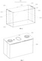
- the insulation patch 224 is configured to coat the electrode assembly 223. As shown in FIG. 6 and FIG. 7 , a side edge of the insulation patch 224 has a hot-melt region 2241 and a non-hot-melt region 2242.
- the hot-melt region 2241 is configured to hot melt with a lower plastic 2212, and the non-hot-melt region 2242 is lower than the hot-melt region 2241.
- the insulation patch 224 is mounted on the shell 222 together with the electrode assembly 223.
- contact of the shell 222 and the insulation patch 224 causes friction on the insulation patch 224, so that an upper edge of the insulation patch 224 is pulled up by a friction force. If the non-hot-melt region 2242 is higher than the hot-melt region 2241 or flush with the hot-melt region 2241, it may cause that the non-hot-melt region 2242 is higher than the lower plastic 2212 when the lower plastic 2212 is hot melted with the hot-melt region 2241.
- the non-hot-melt region 2242 may even exceed an upper surface of the lower plastic 2212 and be in contact with a part of side edge of the top cover member 2211, thereby causing poor welding when the top cover member 2211 and the shell 222 are welded by using a laser.
- the non-hot-melt region 2242 is designed as being lower than the hot-melt region 2241, so that when the insulation patch 224 and the electrode assembly 223 are mounted on the shell 222, an avoidance space is provided for the insulation patch 224 when pulled up by friction, to avoid that the non-hot-melt region 2242 is higher than the lower plastic 2212 when the lower plastic 2212 is hot melted with the hot-melt region 2241, and therefore, poor welding can be avoided when the top cover member 2211 and the shell 222 are welded by using a laser.
- the non-hot-melt region 2242 of the insulation patch 224 is lower than the hot-melt region 2241, so that the non-hot-melt region 2242 of the insulation patch 224 can be avoided to interfere with a welding position between the top cover member 2211 and the shell 222. Therefore, when the top cover member 2211 and the shell 222 are welded, no dry joint occurs, which helps improve sealing between the top cover member 2211 and the shell 222, prevents leakage of the electrode assembly 223, and further improves safety of the electrode assembly 223.
- an opening in a shape of a rectangle is formed when the insulation patch 224 coats the electrode assembly.
- a side wall of the insulation patch 224 corresponding to a long edge of the rectangle has a plurality of the hot-melt regions 2241.
- a groove is formed in adjacent two of the hot-melt regions 2241, so that the non-hot-melt region 2242 is lower than the hot-melt region 2241.
- a groove is formed between adjacent hot-melt regions 2241, so that the non-hot-melt region 2242 is lower than the hot-melt region 2241, and a plurality of hot-melt regions 2241 are disposed on a long edge of the opening of the insulation patch 224, to better match with a hot-melt position of the lower plastic, so that the hot-melt region 2241 of the insulation patch 224 is better hot melted together with the hot-melt position of the lower plastic, and connection strength of the insulation patch 224 and the lower plastic is increased.
- hot-melt regions 2241 are disposed on a long edge of the opening of the insulation patch 224 is used as an example for description, but how many hot-melt regions 2241 are disposed on a long edge of the opening of the insulation patch 224 is not limited.
- a quantity of hot-melt regions 2241 disposed on a long edge of the opening of the insulation patch 224 is set according to a hot-melt position of the lower plastic.
- the groove is in a square or arc shape.
- FIG. 8 is an unfolded diagram of the insulation patch 224 according to an embodiment of the present disclosure, where the groove is an arc-shaped groove 2243.
- the groove is designed as the arc-shaped groove 2243, so that the groove is easier to be formed in the adjacent hot-melt region 2241 and easy to process.
- FIG. 9 is an unfolded diagram of another insulation patch 224 according to an embodiment of the present disclosure, where the groove is a square groove 2244.
- the groove is designed as the square groove 2244, so that the groove is easier to be formed in the adjacent hot-melt region 2241 and easy to process.
- a depth H of the groove ranges from 2 mm to 5 mm.
- the depth H of the groove is 2 mm, 3 mm..., or 5 mm, which is not listed herein.
- a phenomenon that the non-hot-melt region 2242 of the insulation patch 224 may interfere with a welding position between the top cover assembly and the shell because the depth H of the groove is too small (for example, less than 2 mm) can be further avoided.
- a phenomenon that a part of the electrode assembly may be exposed and be in contact with the shell when the electrode assembly is coated with the insulation patch 224 because the depth H of the groove is too large (for example, greater than 5 mm) can be further avoided.
- an opening in a shape of a rectangle is formed when the insulation patch 224 coats the electrode assembly.
- a side wall of the insulation patch 224 corresponding to a short edge of the rectangle has one hot-melt region 2241.
- an orthographic projection along a thickness direction of the insulation patch 224 when the insulation patch 224 is unfolded is I-shaped, and includes a first part 2245 located in the middle and a second part 2246 and a third part 2247 located at two ends of the first part 2245.
- the first part 2245 is configured to cover a bottom surface of the electrode assembly, and the second part 2246 and the third part 2247 are folded separately toward the electrode assembly, so that the second part 2246 and the third part 2247 that do not protrude from the first part 2245 respectively cover a first side and a second side of the electrode assembly that are opposite to each other, where the first side and the second side respectively correspond to two long edges of the rectangle.
- the second part 2246 and the third part 2247 that protrude from the first part 2245 are folded separately toward the electrode assembly, and cover a third side and a fourth side of the electrode assembly that are opposite to each other, where the third side and the fourth side respectively correspond to two short edges of the rectangle.
- the orthographic projection along a thickness direction of the insulation patch 224 when the insulation patch 224 is unfolded is I-shaped, so that a manner of coating the electrode assembly with the insulation patch 224 is simpler, and time for assembling can be reduced.
- the overlap region 2241 is formed by using the foregoing overlap region, so that strength of the hot-melt region 2241 can be increased.
- chamfered spacers R are disposed at corner positions of the second part 2246 and the third part 2247 that are away from the first part 2245. By disposing the chamfered spacers R, an overlap region between the second part 2246 and the third part 2247 can be prevented from interfering with the welding position between the top cover assembly and the shell due to bulge.
- an angle of a chamfered spacer R ranges from 4 degrees to 20 degrees. For example, 4 degrees, 8 degrees..., or 20 degrees, which is not listed herein.
- a phenomenon that the non-hot-melt region 2242 of the insulation patch 224 may interfere with the welding position between the top cover assembly and the shell because the angle of the chamfered spacer R is too small (for example, less than 4 degrees) can be further avoided.
- a phenomenon that a part of the electrode assembly may be exposed and be in contact with the shell when the electrode assembly is coated with the insulation patch 224 because the angle of the chamfered spacer is too large (for example, greater than 20 degrees) can be further avoided.
- a shape of the chamfered spacer R is a triangle or a trapezoid.
- the shape of the chamfered spacer R is designed as a triangle or a trapezoid, so that an overlap region formed by the second part 2246 and the third part 2247 after the electrode assembly is coated can better match the hot-melt position of the lower plastic, and the chamfered spacer R is easier to be processed.
- the present disclosure provides an insulation patch configured to coat the electrode assembly. As shown in FIG. 6 , a side edge of the insulation patch 224 has the hot-melt region 2241 and the non-hot-melt region 2242.
- the hot-melt region 2241 is configured to hot melt with a lower plastic, and the non-hot-melt region 2242 is lower than the hot-melt region 2241.
- An opening in a shape of a rectangle is formed when the insulation patch 224 coats the electrode assembly.
- a side wall of the insulation patch 224 corresponding to a long edge of the rectangle has a plurality of the hot-melt regions.
- a side wall of the insulation patch 224 corresponding to a short edge of the rectangle has one hot-melt region.
- a groove is formed in adjacent two of the hot-melt regions 224 on the side wall of the insulation patch 224 corresponding to the long edge of the rectangular, so that the non-hot-melt region 2242 is lower than the hot-melt region 2241.
- an orthographic projection along a thickness direction of the insulation patch 224 when the insulation patch 224 is unfolded is I-shaped, and includes the first part 2245 located in the middle and the second part 2246 and the third part 2247 located at two ends of the first part 2245.
- the first part 2245 is configured to cover a bottom surface of the electrode assembly, and the second part 2246 and the third part 2247 are folded separately toward the electrode assembly, so that the second part 2246 and the third part 2247 that do not protrude from the first part 2245 respectively cover the first side and the second side of the electrode assembly that are opposite to each other, where the first side and the second side respectively correspond to the two long edges of the rectangle.
- the second part 2246 and the third part 2247 that protrude from the first part 2245 are folded separately toward the electrode assembly, and cover the third side and the fourth side of the electrode assembly that are opposite to each other, where the third side and the fourth side respectively correspond to the two short edges of the rectangle.
- the non-hot-melt region 2242 of the insulation patch 224 is lower than the hot-melt region 2241, so that the non-hot-melt region 2242 of the insulation patch 224 can be avoided to interfere with a welding position between the top cover assembly and the shell. Therefore, when the top cover assembly and the shell are welded, no dry joint occurs, which helps improve sealing between the top cover assembly and the shell, prevents leakage of the electrode assembly, and further improves safety of the electrode assembly.
Landscapes
- Chemical & Material Sciences (AREA)
- Chemical Kinetics & Catalysis (AREA)
- Electrochemistry (AREA)
- General Chemical & Material Sciences (AREA)
- Connection Of Batteries Or Terminals (AREA)
- Sealing Battery Cases Or Jackets (AREA)
Abstract
Description
- The present disclosure relates to the battery field, and in particular, to an insulation patch, a battery cell, a battery, and a device.
- Currently, with increasing vehicle electrification, China has seen an increasing number of electric vehicles. With the development of the electric vehicles, batteries become the key to sustainable development of the automobile industry. A battery production technology is another important factor affecting the development of the electric vehicles. In the production process of a battery, when a bare electrochemical cell is mounted in an accommodating space formed by a shell and a top cover, an insulation patch needs to be wrapped outside the bare electrochemical cell, to achieve insulation between the bare electrochemical cell and the shell.
- However, in the conventional technology, due to interference from an insulation patch, when a shell and a top cover are welded by using a laser, poor welding may occur, thereby causing poor sealing between the shell and the top cover, and even causing a leakage of an electrochemical cell in the shell and the top cover, which affects safety of the electrochemical cell.
- In view of the foregoing problems, the present disclosure provides an insulation patch, a battery cell, a battery, and a device. A non-hot-melt region of the insulation patch does not interfere with a welding position between a top cover member and a shell. Therefore, when the top cover member and the shell are welded, no dry joint occurs, which helps improve sealing between the top cover member and the shell, prevents leakage of an electrode assembly, and improves safety of the electrode assembly.
- According to a first aspect, the present disclosure provides an insulation patch, configured to coat an electrode assembly, and a side edge of the insulation patch has a hot-melt region and a non-hot-melt region. The hot-melt region is configured to hot melt with a lower plastic, and the non-hot-melt region is lower than the hot-melt region.
- In the technical solution of this embodiment of the present disclosure, after the electrode assembly coated with the insulation patch is mounted to the shell, and the hot-melt region of the insulation patch is hot melted to the lower plastic of a top cover assembly, when a top cover member and the shell are welded together by using a laser, the non-hot-melt region of the insulation patch is lower than the hot-melt region, preventing the non-hot-melt region of the insulation patch from interfering with a welding position between the top cover member and the shell. Therefore, when the top cover member and the shell are welded, no dry joint occurs, which helps improve sealing between the top cover member and the shell, prevents leakage of the electrode assembly, and further improves safety of the electrode assembly.
- In some embodiments, an opening in a shape of a rectangle is formed when the insulation patch coats the electrode assembly. A side wall of the insulation patch corresponding to a long edge of the rectangle has a plurality of the hot-melt regions. A groove is formed in adjacent two of the hot-melt regions, so that the non-hot-melt region is lower than the hot-melt region.
- In this embodiment, a groove is formed between adjacent hot-melt regions, so that the non-hot-melt region is lower than the hot-melt region, and a plurality of hot-melt regions are disposed on a long edge of the opening of the insulation patch, to better match with a hot-melt position of the lower plastic, so that a hot-melt region of the insulation patch is better hot melted together with the hot-melt position of the lower plastic, and connection strength of the insulation patch and the lower plastic is increased.
- In some embodiments, the groove is in a square or arc shape. The groove is designed as a square or an arc shape, so that the groove is easier to be formed in the adjacent hot-melt region and easy to process.
- In some embodiments, a depth of the groove ranges from 2 mm to 5 mm. In this embodiment, a phenomenon that the non-hot-melt region of the insulation patch may interfere with the welding position between the top cover member and the shell because the depth of the groove is too small (for example, less than 2 mm) can be further avoided. In this embodiment, a phenomenon that a part of the electrode assembly may be exposed and be in contact with the shell when the electrode assembly is coated with the insulation patch because the groove is excessively deep (for example, greater than 5 mm) can be further avoided.
- In some embodiments, a side wall of the insulation patch corresponding to a short edge of the rectangle has one hot-melt region. In this design manner, the insulation patch can better match the hot-melt position of the lower plastic, so that the hot-melt region of the insulation patch is better hot melted together with the hot-melt position of the lower plastic.
- In some embodiments, an orthographic projection along a thickness direction of the insulation patch when the insulation patch is unfolded is I-shaped, and includes a first part located in the middle and a second part and a third part located at two ends of the first part. The first part is configured to cover a bottom surface of the electrode assembly, and the second part and the third part are folded separately toward the electrode assembly, so that the second part and the third part that do not protrude from the first part respectively cover a first side and a second side of the electrode assembly that are opposite to each other, where the first side and the second side respectively correspond to two long edges of the rectangle. The second part and the third part that protrude from the first part are folded separately toward the electrode assembly, and cover a third side and a fourth side of the electrode assembly that are opposite to each other, where the third side and the fourth side respectively correspond to two short edges of the rectangle.
- In this embodiment, the orthographic projection along a thickness direction of the insulation patch when the insulation patch is unfolded is I-shaped, so that a manner of coating the electrode assembly with the insulation patch is simpler, and time for assembling can be reduced.
- In some embodiments, there is an overlap region when the second part and the third part that protrude from the first part cover the third side and the fourth side, and the overlap region forms the hot-melt region. The hot-melt region is formed by using the foregoing overlap region, so that strength of the hot-melt region can be increased.
- In some embodiments, chamfered spacers are disposed at corner positions of the second part and the third part that are away from the first part. By disposing the chamfered spacers, an overlap region between the second part and the third part can be prevented from interfering with the welding position between the top cover member and the shell due to bulge.
- In some embodiments, an angle of a chamfered spacer ranges from 4 degrees to 20 degrees. In this embodiment, a phenomenon that the non-hot-melt region of the insulation patch may interfere with the welding position between the top cover member and the shell because the angle of the chamfered spacer is too small (for example, less than 4 degrees) can be further avoided. In this embodiment, a phenomenon that a part of the electrode assembly may be exposed and be in contact with the shell when the electrode assembly is coated with the insulation patch because the angle of the chamfered spacer is too large (for example, greater than 20 degrees) can be further avoided.
- In some embodiments, a shape of the chamfered spacer is a triangle or a trapezoid. The shape of the chamfered spacer is designed as a triangle or a trapezoid, so that an overlap region formed by the second part and the third part after the electrode assembly is coated can better match the hot-melt position of the lower plastic, and the chamfered spacer is easier to be processed.
- According to a second aspect, the present disclosure further provides a battery cell, including: a top cover assembly, a shell, an electrode assembly, and an insulation patch in any one of the foregoing embodiments. The top cover assembly includes a top cover member and a lower plastic bonded to the top cover member. The shell and the top cover assembly form an enclosed space. The electrode assembly is located in the enclosed space. The insulation patch coats the electrode assembly in the enclosed space, and is hot melted to the lower plastic via a hot-melt region. A pole on the top cover member is connected to a tab of the electrode assembly.
- In the technical solution of this embodiment, the battery cell includes the insulation patch in any one of the foregoing embodiments. Therefore, in this embodiment, after the electrode assembly coated with the insulation patch is mounted to the shell, and the hot-melt region of the insulation patch is hot melted to the lower plastic of the top cover assembly, when the top cover member and the shell are welded together by using a laser, a non-hot-melt region of the insulation patch is lower than the hot-melt region, preventing the non-hot-melt region of the insulation patch from interfering with a welding position between the top cover member and the shell. Therefore, when the top cover member and the shell are welded, no dry joint occurs, which helps improve sealing between the top cover member and the shell, prevents leakage of the electrode assembly, and improves safety of the electrode assembly.
- In some embodiments, the battery cell further includes a switching member, the switching member is located between the top cover member and the electrode assembly, and the pole on the top cover member is connected to the tab of the electrode assembly by using the switching member. In this embodiment, the pole on the top cover member is connected to the tab of the electrode assembly by using the switching member.
- According to a third aspect, the present disclosure further provides a battery, where the battery includes a plurality of the battery cells in any one of the foregoing embodiments.
- According to a fourth aspect, the present disclosure further provides a device using a battery as a power supply, and the battery in this embodiment is the battery in any one of the foregoing embodiments.
- By reading the detailed description of the following preferred embodiments, various other advantages and benefits will be clear and apparent to those of ordinary skill in the art. The accompanying drawings are provided merely to illustrate the preferred embodiments, rather than to limit the present disclosure. Same components are represented by same reference numerals throughout the accompanying drawings. In the accompanying drawings:
-
FIG. 1 is a schematic diagram of a structure of a vehicle according to some embodiments of the present disclosure; -
FIG. 2 is an exploded diagram of a battery according to some embodiments of the present disclosure; -
FIG. 3 is an exploded diagram of a battery cell according to some embodiments of the present disclosure; -
FIG. 4 is a front view of a battery cell according to some embodiments of the present disclosure; -
FIG. 5 is a schematic diagram of a structure of a battery cell according to some embodiments of the present disclosure; -
FIG. 6 is a schematic diagram of a structure of an insulation patch when an electrode assembly is coated according to some embodiments of the present disclosure; -
FIG. 7 is a schematic diagram of a positional relationship between a top cover assembly and an insulation patch according to some embodiments of the present disclosure; -
FIG. 8 is an unfolded diagram of an insulation patch according to some embodiments of the present disclosure; and -
FIG. 9 is an unfolded diagram of another insulation patch according to some embodiments of the present disclosure. - Reference numerals of the accompanying drawings in a specific implementation are as follows:
1 - vehicle; 2 - battery; 3 - controller; 4 - motor; 21 - case; 22 - battery cell; 211 - first case assembly; 212 - second case assembly; 213 - accommodating space; 221 - top cover assembly; 222 - shell; 223 - electrode assembly; 224 - insulation patch; 225 - switching member; 2211- top cover member; 2212 - lower plastic; 2241 - hot-melt region; 2242 - non-hot-melt region; 2243- arc-shaped groove; 2244 - square groove; H - depth of a groove; 2245 - first part; 2246 - second part; 2247 - third part; R - chamfered spacer; 5 -; 6 -; 7-. - Embodiments of the technical solutions of the present disclosure will be described in detail below with reference to the accompanying drawings. The following embodiments are merely used to more clearly illustrate the technical solutions of the present disclosure. Therefore, these embodiments are merely exemplary and are not intended to limit the protection scope of the present disclosure.
- Unless otherwise defined, all technical and scientific terms used in this specification have the same meanings as those commonly understood by those skilled in the art of the present disclosure. The terms used in this specification are merely intended to describe specific embodiments, and are not intended to limit the present disclosure. The terms "includes" and "has" in the specification and claims of the present disclosure and the foregoing description of the accompanying drawings and any modification thereof are intended to cover non-exclusive inclusion.
- In the description of the embodiments of the present disclosure, technical terms "first", "second", and the like are used merely to distinguish different objects, and cannot be understood as indicating or implying relative importance or implying a quantity, a specific sequence, or a primary and secondary relationship of the indicated technical features. In the description of the embodiments of the present disclosure, "a plurality of' means two or more, unless otherwise specifically defined.
- The "embodiment" mentioned herein means that a specific feature, structure or characteristic described in combination with the embodiment can be included in at least one embodiment of the present disclosure. The phrase appearing in different parts of the specification does not necessarily refer to the same embodiment or an independent or alternative embodiment exclusive of other embodiments. It may be explicitly or implicitly appreciated by those skilled in the art that the embodiments described herein may be combined with another embodiment.
- In the description of the embodiments of the present disclosure, the term "and/or" merely describes associations between associated objects, and it indicates three types of relationships. For example, A and/or B may indicate that A exists alone, A and B exist at the same time, or B exists alone. In addition, the character "/" in this specification generally indicates that the associated objects are in an "or" relationship.
- In the description of the embodiments of the present disclosure, the technical terms such as "central", "longitudinal", "transverse", "length", "width", "thickness", "upper", "lower", "front", "back", "left", "right", "vertical", "horizontal", "top", "bottom", "inner", "outer", "clockwise", "anticlockwise", "axial direction", "radial direction" and "circumferential direction" are orientations or positional relationships shown based on the accompanying drawings. These terms are merely intended to facilitate describing the embodiments of the present disclosure and make the description simple, rather than to indicate or imply that a mentioned device or element must have a specific orientation or be constructed and operated in the specific orientation. Therefore, these terms cannot be construed as a limitation to the present disclosure.
- In the description of the embodiments of the present disclosure, unless otherwise clearly specified and defined, the technical terms such as "mounting", "interconnection", "connection" and "fixation" should be understood in a broad sense. For example, the "connection" may be a fixed connection, removable connection or integral connection; may be a mechanical connection or electrical connection; may be a direct connection or indirect connection through a medium; and may be a communication or interaction between two elements. Those of ordinary skill in the art may understand specific meanings of the foregoing terms in the embodiments of the present disclosure based on a specific situation.
- At present, with the development of the market, a power battery is widely used. The power battery is not only applied to a power storage system such as a hydraulic power, a fire power, a wind power, and a solar power plant, but also widely used in electric transportation, such as an electric bicycle, an electric motorcycle, and an electric vehicle, and various fields, such as military equipment, and aerospace. With the development of electric transportation, military equipment, aerospace, and the like, batteries have become the key to sustainable development of the automotive industry. A battery technology is another important factor in the development of electric devices such as electric transportation, military equipment, and aerospace.
- The inventor notes that, in a production process of a battery, when a bare electrochemical cell is mounted in an accommodating space formed by a shell and a top cover, an insulation patch needs to be wrapped outside the bare electrochemical cell, to achieve an effect of insulation between the bare electrochemical cell and the shell. However, due to interference from the insulation patch, when a shell and a top cover are welded by using a laser, poor welding may occur, thereby causing poor sealing between the shell and the top cover, and even causing a leakage of an electrochemical cell in the shell and the top cover, which affects safety of the electrochemical cell.
- Based on the foregoing, to resolve the foregoing problems, the applicant has designed an insulation patch, a battery cell, a battery, and a device after in-depth research. A non-hot-melt region of the insulation patch does not interfere with a welding position of the top cover and the shell. Therefore, when a top cover member and the shell are welded, no dry joint occurs, which helps improve sealing between the top cover member and the shell, prevents leakage of an electrode assembly, and improves safety of the electrode assembly.
- The battery mentioned in the present disclosure includes battery cells. The battery may include a rechargeable lithium battery, a lithium-ion primary battery, a lithium sulfide battery, a sodium lithium-ion battery, a sodium ion battery, a magnesium ion battery, or the like. This is not limited in the embodiments of the present disclosure. The battery is applicable to various electric devices.
- The electric device may be a mobile phone, a portable device, a laptop, an electric motorcycle, an electric vehicle, a steamship, a spacecraft, an electric toy, an electric tool, or the like. The vehicle may be a fuel vehicle, a gas vehicle, or a new energy vehicle, and the new energy vehicle may be a pure electric vehicle, a hybrid vehicle, an extended-range vehicle, or the like. For example, the spacecraft includes an airplane, a rocket, a spaceshuttle, and a spaceship; the electric toy includes a stationary or mobile electric toy, such as a game console, an electric toy car, an electric toy ship, and an electric toy plane; and the electric tool includes a metal cutting electric tool, a grinding electric tool, an assembly electric tool, and a railway electric tool, such as an electric drill, an electric grinding machine, an electric wrench, an electric screwdriver, an electric hammer, an electric impact drill, a concrete vibrator, and an electric planer. The embodiments of the present disclosure set no special limitation on the foregoing electric device.
- According to some embodiments of the present disclosure, this embodiment provides a device using a battery as a power supply. The device can be, for example, but is not limited to, a vehicle, a ship, or an aircraft. As shown in
FIG. 1, FIG. 1 is a schematic diagram of a structure of one vehicle according to some embodiments of the present disclosure. Abattery 2 is disposed inside avehicle 1, and thebattery 2 can be disposed at a bottom, a head, or a tail of thevehicle 1. Thebattery 2 can be configured to supply power to thevehicle 1. For example, thebattery 2 may be used as an operational power supply of thevehicle 1. - The
vehicle 1 can further include acontroller 3 and amotor 4. Thecontroller 3 is configured to control thebattery 2 to supply power to themotor 4, for example, is configured to enable, navigate, and drive thevehicle 1. - In some embodiments of the present disclosure, the
battery 2 can be used not only as the operational power supply of thevehicle 1, but also as a driving power supply of thevehicle 1, in place of or partly in place of fuel or natural gas to provide a driving power for thevehicle 1. - According to some embodiments of the present disclosure, this embodiment provides a battery.
FIG. 2 is an exploded diagram of thebattery 2 according to some embodiments of the present disclosure. As shown inFIG. 2 , thebattery 2 includes acase 21 and abattery cell 22, and thebattery cell 22 is accommodated in thecase 21. Thebattery cell 22 may be formed by a plurality of battery modules. Thecase 21 is configured to accommodate thebattery cell 22, and thecase 21 may be of a plurality of structures. In some embodiments, thecase 21 can include afirst case assembly 211 and asecond case assembly 212, thefirst case assembly 211 and thesecond case assembly 212 are mutually covered, and thefirst case assembly 211 and thesecond case assembly 212 jointly define anaccommodating space 213 for accommodating thebattery cell 22. Thesecond case assembly 212 can be of a hollow structure with one end opening, thefirst case assembly 211 is a platy structure, and thefirst case assembly 211 covers an opening side of thesecond case assembly 212, so as to form thecase 21 with theaccommodating space 213. Both thefirst case assembly 211 and thesecond case assembly 212 can be hollow structures with each side opening. An opening side of thefirst case assembly 211 covers an opening side of thesecond case assembly 212, so as to form thecase 21 with theaccommodating space 213. Certainly, thefirst case assembly 211 and thesecond case assembly 212 may be in a plurality of shapes, such as a cylinder or a cuboid. - According to some embodiments of the present disclosure, this embodiment provides a battery cell. As shown in
FIG. 3 to FIG. 5 ,FIG. 3 is an exploded view of the battery cell according to some embodiments of the present disclosure.FIG. 4 is a front view of the battery cell according to some embodiments of the present disclosure.FIG. 5 is a schematic diagram of a structure of the battery cell according to some embodiments of the present disclosure. - As shown in
FIG. 3 to FIG. 5 , the battery cell includes atop cover assembly 221, ashell 222, anelectrode assembly 223, and aninsulation patch 224. Thetop cover assembly 221 includes atop cover member 2211 and a lower plastic 2212 bonded to thetop cover member 2211. Theshell 222 and thetop cover assembly 221 form an enclosed space. Theelectrode assembly 223 is located in the enclosed space. Theinsulation patch 224 coats theelectrode assembly 223 in the enclosed space, and is hot melted to thelower plastic 2212 via a hot-melt region. A pole on thetop cover member 2211 is connected to a tab of theelectrode assembly 223. - The
shell 222 and thetop cover assembly 221 form a shell, and the shell can be of a plurality of shapes, such as a cylinder or a cuboid. A shape of the shell can be determined according to a specific shape of theelectrode assembly 223. For example, if theelectrode assembly 223 is in a cylindrical structure, the shell can be in a cylindrical structure. If theelectrode assembly 223 is a cuboid structure, the shell can be in a cuboid structure. - The battery cell further includes an electrolyte. The
shell 222 can accommodate an electrolyte, so as to provide an enclosed space for the electrode assembly and the electrolyte. - A
shell 224 may be in a structure with one side opening, and there is only onetop cover assembly 221 disposed and thetop cover assembly 221 covers an opening of theshell 224. Alternatively, theshell 224 may be in a structure with two sides opening, twotop cover assemblies 221 are provided, and the twotop cover assemblies 221 respectively cover two openings of theshell 224. - For example, the
top cover assembly 221 is connected to theshell 224 by means of welding, bonding, clamping, or other means. - In some embodiments, with reference to
FIG. 3 , the battery cell may further include acathode terminal 5, ananode terminal 6, and apressure relief mechanism 7, and thecathode terminal 5, theanode terminal 6, and thepressure relief mechanism 7 are all mounted on thetop cover assembly 221. Both thecathode terminal 5 and theanode terminal 6 are configured to be electrically connected to a cathode plate and an anode plate, so as to lead out electric energy generated by theelectrode assembly 223. Thepressure relief mechanism 7 is configured to discharge internal pressure of the battery cell when the internal pressure of the battery cell reaches a predetermined value. - For example, the
pressure relief mechanism 7 is located between thecathode terminal 5 and theanode terminal 6, and thepressure relief mechanism 7 can be components such as an explosion-proof valve, an explosion-proof plate, an air valve, a pressure relief valve, or a safety valve. - There may be one or
more electrode assemblies 223. For example, as shown inFIG. 3 , there are twoelectrode assemblies 223. - The electrode assembly includes a cathode plate, an anode plate, and a separator. The battery cell works mainly depending on lithium ions to move between the cathode plate and the anode plate. The cathode plate includes a cathode current collector and a cathode active material layer, and a surface of the cathode current collector is coated with the cathode active material layer. The cathode current collector includes a cathode current collector part and a positive tab. The cathode current collector part is coated with the cathode active material layer, and the positive tab is not coated with the cathode active material layer. A lithium-ion battery is used as an example. A material of the cathode current collector may be aluminum, the cathode active material layer includes a cathode active material, and the cathode active material may be lithium cobalt oxides, lithium iron phosphate, ternary lithium, or lithium manganese. The anode plate includes an anode current collector and an anode active material layer, and a surface of the anode current collector is coated with the anode active material layer. The anode current collector includes an anode current collector part and an anode tab. The anode current collector part is coated with the anode active material layer, and the anode tab is not coated with the anode active material layer. A material of the anode current collector may be copper, the anode active material layer includes an anode active material, and the anode active material may be carbon or silicon. A material of the separator may be PP (polypropylene, polypropylene), PE (polyethylene, polyethylene), or the like.
- According to some embodiments of the present disclosure, the battery cell further includes a switching
member 225, the switchingmember 225 is located between thetop cover member 2211 and theelectrode assembly 223, and the pole on thetop cover member 2211 is connected to the tab of theelectrode assembly 223 by using the switchingmember 225. In this embodiment, the pole on thetop cover member 2211 is connected to the tab of theelectrode assembly 223 by using the switchingmember 225. - According to some embodiments of the present disclosure, this embodiment provides an insulation patch. With reference to
FIG. 6, FIG. 6 is a schematic diagram of a structure of the insulation patch when an electrode assembly is coated according to some embodiments of the present disclosure.FIG. 7 is a schematic diagram of a positional relationship between thetop cover assembly 221 and theinsulation patch 224. - With reference to
FIG. 3 , theinsulation patch 224 is configured to coat theelectrode assembly 223. As shown inFIG. 6 and FIG. 7 , a side edge of theinsulation patch 224 has a hot-melt region 2241 and a non-hot-melt region 2242. The hot-melt region 2241 is configured to hot melt with a lower plastic 2212, and the non-hot-melt region 2242 is lower than the hot-melt region 2241. - For example, after coating the
electrode assembly 223, theinsulation patch 224 is mounted on theshell 222 together with theelectrode assembly 223. When theinsulation patch 224 and theelectrode assembly 223 are mounted on theshell 222, contact of theshell 222 and theinsulation patch 224 causes friction on theinsulation patch 224, so that an upper edge of theinsulation patch 224 is pulled up by a friction force. If the non-hot-melt region 2242 is higher than the hot-melt region 2241 or flush with the hot-melt region 2241, it may cause that the non-hot-melt region 2242 is higher than the lower plastic 2212 when thelower plastic 2212 is hot melted with the hot-melt region 2241. In addition, because thelower plastic 2212 is very thin, the non-hot-melt region 2242 may even exceed an upper surface of thelower plastic 2212 and be in contact with a part of side edge of thetop cover member 2211, thereby causing poor welding when thetop cover member 2211 and theshell 222 are welded by using a laser. - In the present disclosure, the non-hot-
melt region 2242 is designed as being lower than the hot-melt region 2241, so that when theinsulation patch 224 and theelectrode assembly 223 are mounted on theshell 222, an avoidance space is provided for theinsulation patch 224 when pulled up by friction, to avoid that the non-hot-melt region 2242 is higher than the lower plastic 2212 when thelower plastic 2212 is hot melted with the hot-melt region 2241, and therefore, poor welding can be avoided when thetop cover member 2211 and theshell 222 are welded by using a laser. - In conclusion, after the
electrode assembly 223 coated with theinsulation patch 224 is mounted to theshell 222, and the hot-melt region 2241 of aninsulation patch 225 is hot melted to thelower plastic 2212 of thetop cover assembly 221, when thetop cover member 2211 and theshell 222 are welded together by using a laser, the non-hot-melt region 2242 of theinsulation patch 224 is lower than the hot-melt region 2241, so that the non-hot-melt region 2242 of theinsulation patch 224 can be avoided to interfere with a welding position between thetop cover member 2211 and theshell 222. Therefore, when thetop cover member 2211 and theshell 222 are welded, no dry joint occurs, which helps improve sealing between thetop cover member 2211 and theshell 222, prevents leakage of theelectrode assembly 223, and further improves safety of theelectrode assembly 223. - According to some embodiments of the present disclosure, with reference to
FIG. 6 , an opening in a shape of a rectangle is formed when theinsulation patch 224 coats the electrode assembly. A side wall of theinsulation patch 224 corresponding to a long edge of the rectangle has a plurality of the hot-melt regions 2241. A groove is formed in adjacent two of the hot-melt regions 2241, so that the non-hot-melt region 2242 is lower than the hot-melt region 2241. - In this embodiment, a groove is formed between adjacent hot-
melt regions 2241, so that the non-hot-melt region 2242 is lower than the hot-melt region 2241, and a plurality of hot-melt regions 2241 are disposed on a long edge of the opening of theinsulation patch 224, to better match with a hot-melt position of the lower plastic, so that the hot-melt region 2241 of theinsulation patch 224 is better hot melted together with the hot-melt position of the lower plastic, and connection strength of theinsulation patch 224 and the lower plastic is increased. It should be noted that, in this embodiment and the accompanying drawings, that three hot-melt regions 2241 are disposed on a long edge of the opening of theinsulation patch 224 is used as an example for description, but how many hot-melt regions 2241 are disposed on a long edge of the opening of theinsulation patch 224 is not limited. In an actual application, a quantity of hot-melt regions 2241 disposed on a long edge of the opening of theinsulation patch 224 is set according to a hot-melt position of the lower plastic. - According to some embodiments of the present disclosure, the groove is in a square or arc shape. As shown in
FIG. 8, FIG. 8 is an unfolded diagram of theinsulation patch 224 according to an embodiment of the present disclosure, where the groove is an arc-shapedgroove 2243. The groove is designed as the arc-shapedgroove 2243, so that the groove is easier to be formed in the adjacent hot-melt region 2241 and easy to process. - Alternatively, in another embodiment, as shown in
FIG. 9, FIG. 9 is an unfolded diagram of anotherinsulation patch 224 according to an embodiment of the present disclosure, where the groove is asquare groove 2244. The groove is designed as thesquare groove 2244, so that the groove is easier to be formed in the adjacent hot-melt region 2241 and easy to process. - According to some embodiments of the present disclosure, with reference to
FIG. 6 , a depth H of the groove ranges from 2 mm to 5 mm. For example, the depth H of the groove is 2 mm, 3 mm..., or 5 mm, which is not listed herein. In this embodiment, a phenomenon that the non-hot-melt region 2242 of theinsulation patch 224 may interfere with a welding position between the top cover assembly and the shell because the depth H of the groove is too small (for example, less than 2 mm) can be further avoided. In this embodiment, a phenomenon that a part of the electrode assembly may be exposed and be in contact with the shell when the electrode assembly is coated with theinsulation patch 224 because the depth H of the groove is too large (for example, greater than 5 mm) can be further avoided. - According to some embodiments of the present disclosure, with reference to
FIG. 6 , an opening in a shape of a rectangle is formed when theinsulation patch 224 coats the electrode assembly. A side wall of theinsulation patch 224 corresponding to a short edge of the rectangle has one hot-melt region 2241. Generally, there is one hot-melt position corresponding to a short edge of theinsulation patch 224. Therefore, in this design manner, theinsulation patch 224 can better match the hot-melt position of the lower plastic, so that the hot-melt region 2241 of theinsulation patch 224 is better hot melted together with the hot-melt position of the lower plastic. - According to some embodiments of the present disclosure, as shown in
FIG. 8 andFIG. 9 , an orthographic projection along a thickness direction of theinsulation patch 224 when theinsulation patch 224 is unfolded is I-shaped, and includes afirst part 2245 located in the middle and asecond part 2246 and athird part 2247 located at two ends of thefirst part 2245. Thefirst part 2245 is configured to cover a bottom surface of the electrode assembly, and thesecond part 2246 and thethird part 2247 are folded separately toward the electrode assembly, so that thesecond part 2246 and thethird part 2247 that do not protrude from thefirst part 2245 respectively cover a first side and a second side of the electrode assembly that are opposite to each other, where the first side and the second side respectively correspond to two long edges of the rectangle. Thesecond part 2246 and thethird part 2247 that protrude from thefirst part 2245 are folded separately toward the electrode assembly, and cover a third side and a fourth side of the electrode assembly that are opposite to each other, where the third side and the fourth side respectively correspond to two short edges of the rectangle. - In this embodiment, the orthographic projection along a thickness direction of the
insulation patch 224 when theinsulation patch 224 is unfolded is I-shaped, so that a manner of coating the electrode assembly with theinsulation patch 224 is simpler, and time for assembling can be reduced. - According to some embodiments of the present disclosure, with reference to
FIG. 6 , there is an overlap region when thesecond part 2246 and thethird part 2247 that protrude from thefirst part 2245 cover the third side and the fourth side, and the overlap region forms the hot-melt region 2241. The hot-melt region 2241 is formed by using the foregoing overlap region, so that strength of the hot-melt region 2241 can be increased. - According to some embodiments of the present disclosure, with reference to
FIG. 8 andFIG. 9 , chamfered spacers R are disposed at corner positions of thesecond part 2246 and thethird part 2247 that are away from thefirst part 2245. By disposing the chamfered spacers R, an overlap region between thesecond part 2246 and thethird part 2247 can be prevented from interfering with the welding position between the top cover assembly and the shell due to bulge. - According to some embodiments of the present disclosure, with reference to
FIG. 8 andFIG. 9 , an angle of a chamfered spacer R ranges from 4 degrees to 20 degrees. For example, 4 degrees, 8 degrees..., or 20 degrees, which is not listed herein. In this embodiment, a phenomenon that the non-hot-melt region 2242 of theinsulation patch 224 may interfere with the welding position between the top cover assembly and the shell because the angle of the chamfered spacer R is too small (for example, less than 4 degrees) can be further avoided. In this embodiment, a phenomenon that a part of the electrode assembly may be exposed and be in contact with the shell when the electrode assembly is coated with theinsulation patch 224 because the angle of the chamfered spacer is too large (for example, greater than 20 degrees) can be further avoided. - According to some embodiments of the present disclosure, with reference to
FIG. 8 andFIG. 9 , a shape of the chamfered spacer R is a triangle or a trapezoid. The shape of the chamfered spacer R is designed as a triangle or a trapezoid, so that an overlap region formed by thesecond part 2246 and thethird part 2247 after the electrode assembly is coated can better match the hot-melt position of the lower plastic, and the chamfered spacer R is easier to be processed. - According to some embodiments of the present disclosure, the present disclosure provides an insulation patch configured to coat the electrode assembly. As shown in
FIG. 6 , a side edge of theinsulation patch 224 has the hot-melt region 2241 and the non-hot-melt region 2242. The hot-melt region 2241 is configured to hot melt with a lower plastic, and the non-hot-melt region 2242 is lower than the hot-melt region 2241. - An opening in a shape of a rectangle is formed when the
insulation patch 224 coats the electrode assembly. A side wall of theinsulation patch 224 corresponding to a long edge of the rectangle has a plurality of the hot-melt regions. A side wall of theinsulation patch 224 corresponding to a short edge of the rectangle has one hot-melt region. A groove is formed in adjacent two of the hot-melt regions 224 on the side wall of theinsulation patch 224 corresponding to the long edge of the rectangular, so that the non-hot-melt region 2242 is lower than the hot-melt region 2241. - As shown in
FIG. 8 andFIG. 9 , an orthographic projection along a thickness direction of theinsulation patch 224 when theinsulation patch 224 is unfolded is I-shaped, and includes thefirst part 2245 located in the middle and thesecond part 2246 and thethird part 2247 located at two ends of thefirst part 2245. Thefirst part 2245 is configured to cover a bottom surface of the electrode assembly, and thesecond part 2246 and thethird part 2247 are folded separately toward the electrode assembly, so that thesecond part 2246 and thethird part 2247 that do not protrude from thefirst part 2245 respectively cover the first side and the second side of the electrode assembly that are opposite to each other, where the first side and the second side respectively correspond to the two long edges of the rectangle. Thesecond part 2246 and thethird part 2247 that protrude from thefirst part 2245 are folded separately toward the electrode assembly, and cover the third side and the fourth side of the electrode assembly that are opposite to each other, where the third side and the fourth side respectively correspond to the two short edges of the rectangle. There is an overlap region when thesecond part 2246 and thethird part 2247 that protrude from thefirst part 2245 cover the third side and the fourth side, and the overlap region forms the hot-melt region 2241. - In the technical solution of the embodiments of the present disclosure, after the
electrode assembly 223 coated with theinsulation patch 224 is mounted to theshell 222, and the hot-melt region 2241 of theinsulation patch 224 is hot melted to the lower plastic of the top cover assembly, when the top cover assembly and the shell are welded together by using a laser, the non-hot-melt region 2242 of theinsulation patch 224 is lower than the hot-melt region 2241, so that the non-hot-melt region 2242 of theinsulation patch 224 can be avoided to interfere with a welding position between the top cover assembly and the shell. Therefore, when the top cover assembly and the shell are welded, no dry joint occurs, which helps improve sealing between the top cover assembly and the shell, prevents leakage of the electrode assembly, and further improves safety of the electrode assembly. - Finally, it should be noted that the foregoing embodiments are merely for describing the technical solutions of the present disclosure, but not for limiting the present disclosure. Although the present disclosure is described in detail with reference to the foregoing embodiments, a person of ordinary skill in the art should understand that they may still make modifications to the technical solutions described in the foregoing embodiments or make equivalent replacements to some or all technical features thereof; and these modifications or replacements do not make the essence of corresponding technical solutions departing from the scope of the technical solutions of the embodiments of the present disclosure, and shall fall within the scope of claims and specification of the present disclosure. In particular, as long as there is no structural conflict, the technical features in the embodiments may be combined in any way. The present disclosure is not limited to the specific embodiments disclosed herein, but should include all technical solutions falling within the scope of the claims.
Claims (14)
- An insulation patch, configured to coat an electrode assembly, wherein:
a side edge of the insulation patch has a hot-melt region and a non-hot-melt region, the hot-melt region is configured to hot melt with a lower plastic, and the non-hot-melt region is lower than the hot-melt region. - The insulation patch according to claim 1, wherein an opening in a shape of a rectangle is formed when the insulation patch coats the electrode assembly;a side wall of the insulation patch corresponding to a long edge of the rectangle has a plurality of the hot-melt regions; anda groove is formed in adjacent two of the hot-melt regions, so that the non-hot-melt region is lower than the hot-melt region.
- The insulation patch according to claim 2, wherein the groove is in a square or arc shape.
- The insulation patch according to claim 2 or 3, wherein a depth of the groove ranges from 2 mm to 5 mm.
- The insulation patch according to claim 2, wherein a side wall of the insulation patch corresponding to a short edge of the rectangle has one hot-melt region.
- The insulation patch according to claim 5, wherein an orthographic projection along a thickness direction of the insulation patch when the insulation patch is unfolded is I-shaped, and comprises a first part located in the middle and a second part and a third part located at two ends of the first part;the first part is configured to cover a bottom surface of the electrode assembly, the second part and the third part are folded separately toward the electrode assembly, so that the second part and the third part that do not protrude from the first part respectively cover a first side and a second side of the electrode assembly that are opposite to each other, and the first side and the second side respectively correspond to long edges of the rectangle; andthe second part and the third part that protrude from the first part are folded separately toward the electrode assembly, and cover a third side and a fourth side of the electrode assembly that are opposite to each other, and the third side and the fourth side respectively correspond to short edges of the rectangle.
- The insulation patch according to claim 6, wherein there is an overlap region when the second part and the third part that protrude from the first part cover the third side and the fourth side, and the overlap region forms the hot-melt region.
- The insulation patch according to claim 7, wherein chamfered spacers are disposed at corner positions of the second part and the third part that are away from the first part.
- The insulation patch according to claim 8, wherein an angle of the chamfered spacer ranges from 4 degrees to 20 degrees.
- The insulation patch according to claim 8, wherein a shape of the chamfered spacer is a triangle or a trapezoid.
- A battery cell, comprising:a top cover assembly, comprising a top cover member and a lower plastic bonded to the top cover member;a shell that forms an enclosed space with the top cover assembly;an electrode assembly, located in the enclosed space; andthe insulation patch according to any one of claims 1 to 10, wherein the insulation patch is configured to coat the electrode assembly in the enclosed space, and is hot melted to the lower plastic via the hot-melt region; and a pole on the top cover member is connected to a tab of the electrode assembly.
- The battery cell according to claim 11, wherein the battery cell further comprises:
a switching member, wherein the switching member is located between the top cover member and the electrode assembly, and the pole on the top cover member is connected to the tab of the electrode assembly by using the switching member. - A battery, wherein the battery comprises a plurality of the battery cells according to claim 11 or 12.
- A device using a battery as a power source, wherein the battery is the battery according to claim 13.
Applications Claiming Priority (1)
| Application Number | Priority Date | Filing Date | Title |
|---|---|---|---|
| PCT/CN2022/072090 WO2023133823A1 (en) | 2022-01-14 | 2022-01-14 | Insulating patch, battery cell, battery and device |
Publications (2)
| Publication Number | Publication Date |
|---|---|
| EP4318766A1 true EP4318766A1 (en) | 2024-02-07 |
| EP4318766A4 EP4318766A4 (en) | 2025-02-12 |
Family
ID=87279928
Family Applications (1)
| Application Number | Title | Priority Date | Filing Date |
|---|---|---|---|
| EP22919475.8A Pending EP4318766A4 (en) | 2022-01-14 | 2022-01-14 | INSULATION PATCH, BATTERY CELL, BATTERY AND DEVICE |
Country Status (4)
| Country | Link |
|---|---|
| US (1) | US20240145889A1 (en) |
| EP (1) | EP4318766A4 (en) |
| CN (1) | CN117063339A (en) |
| WO (1) | WO2023133823A1 (en) |
Families Citing this family (3)
| Publication number | Priority date | Publication date | Assignee | Title |
|---|---|---|---|---|
| CN116799391B (en) * | 2023-08-29 | 2023-12-26 | 深圳海辰储能控制技术有限公司 | Lower plastic, energy storage device and electric equipment |
| CN117080533A (en) * | 2023-08-31 | 2023-11-17 | 上海兰钧新能源科技有限公司 | A kind of battery and its application |
| CN117117403B (en) * | 2023-09-08 | 2025-06-13 | 厦门海辰储能科技股份有限公司 | End cover assembly, energy storage device and electrical equipment |
Family Cites Families (12)
| Publication number | Priority date | Publication date | Assignee | Title |
|---|---|---|---|---|
| JP2013080563A (en) * | 2011-09-30 | 2013-05-02 | Sanyo Electric Co Ltd | Laminate-type secondary battery |
| CN203103376U (en) * | 2013-02-01 | 2013-07-31 | 宁德新能源科技有限公司 | Power battery packaging assembly |
| JP6262069B2 (en) * | 2014-05-07 | 2018-01-17 | 日立オートモティブシステムズ株式会社 | Secondary battery |
| CN204927359U (en) * | 2015-09-24 | 2015-12-30 | 宁德时代新能源科技有限公司 | Insulation shell structure and adopt lithium ion power batteries of this insulation shell structure |
| CN109346628B (en) * | 2016-03-28 | 2020-10-02 | 宁德时代新能源科技股份有限公司 | Secondary battery top cover assembly, secondary battery containing same and assembling method |
| CN205429021U (en) * | 2016-03-28 | 2016-08-03 | 宁德时代新能源科技股份有限公司 | Secondary cell top cap subassembly, contain secondary cell of this subassembly |
| JP2019121433A (en) * | 2017-12-28 | 2019-07-22 | 株式会社豊田自動織機 | Power storage device |
| JP2019192518A (en) * | 2018-04-26 | 2019-10-31 | 株式会社豊田自動織機 | Power storage device |
| JP2020098688A (en) * | 2018-12-17 | 2020-06-25 | 株式会社豊田自動織機 | Power storage device |
| JP7118242B2 (en) * | 2019-03-20 | 2022-08-15 | ビークルエナジージャパン株式会社 | secondary battery |
| CN212161863U (en) * | 2020-05-27 | 2020-12-15 | 宁德时代新能源科技股份有限公司 | Secondary battery, battery module, and device using secondary battery as power source |
| CN113851769B (en) * | 2021-09-30 | 2025-12-19 | 厦门海辰储能科技股份有限公司 | Battery cell |
-
2022
- 2022-01-14 CN CN202280023121.0A patent/CN117063339A/en active Pending
- 2022-01-14 EP EP22919475.8A patent/EP4318766A4/en active Pending
- 2022-01-14 WO PCT/CN2022/072090 patent/WO2023133823A1/en not_active Ceased
-
2024
- 2024-01-09 US US18/407,461 patent/US20240145889A1/en active Pending
Also Published As
| Publication number | Publication date |
|---|---|
| CN117063339A (en) | 2023-11-14 |
| EP4318766A4 (en) | 2025-02-12 |
| WO2023133823A1 (en) | 2023-07-20 |
| US20240145889A1 (en) | 2024-05-02 |
Similar Documents
| Publication | Publication Date | Title |
|---|---|---|
| CN116583998B (en) | Battery cell, battery, electric equipment and manufacturing method and equipment of battery cell | |
| US20240128604A1 (en) | Battery cell, battery, electrical device, and manufacturing method and device for battery cell | |
| US20230123940A1 (en) | Battery cell, battery and power consuming device | |
| EP4293769A1 (en) | Battery cell, battery, and electric device | |
| US11757161B2 (en) | Battery cell, battery and electricity consuming device | |
| US20240145889A1 (en) | Insulation patch, battery cell, battery, and device | |
| EP4195399A1 (en) | Wound electrode assembly, battery cell, battery and electrical device | |
| US12176551B2 (en) | Battery cell, battery, electrical device, and manufacturing method and device for battery cell | |
| US20230178860A1 (en) | Battery cell, battery, power consuming device, and method and apparatus for manufacturing battery cell | |
| US20240356116A1 (en) | Battery cell, battery, electrical device, and manufacturing device and method for battery cell | |
| US20250105474A1 (en) | Battery cell, battery, and electric apparatus | |
| US20240322375A1 (en) | Battery cell, method and apparatus for manufacturing same, battery, and power consuming device | |
| CN220290875U (en) | Battery cells, batteries and electrical devices | |
| US20240429504A1 (en) | Battery cell and manufacturing method therefor and battery | |
| EP4738557A1 (en) | Battery cell, battery and electric device | |
| US20240055705A1 (en) | Battery cell, battery, power consuming apparatus, and method and apparatus for manufacturing battery cell | |
| JP2025524648A (en) | Battery cells, batteries and power consuming devices | |
| WO2023246152A1 (en) | Battery cell, battery, and electrical device | |
| US20250030126A1 (en) | Battery cell, battery and electric device | |
| US20240380080A1 (en) | Battery cell, battery, electrical device, and method and device for manufacturing battery cell | |
| US20240313337A1 (en) | End Cover, Battery Cell, Battery, and Electrical Device | |
| US11984622B1 (en) | Battery cell, method and apparatus of manufacturing the same, battery, and electric apparatus | |
| CN116941075A (en) | Current collecting component, battery monomer, battery and electric equipment | |
| US20240372178A1 (en) | Battery, electrical device, method for manufacturing battery, and device for manufacturing battery | |
| US20250174851A1 (en) | End cover assembly, battery pack, battery, and electrical device |
Legal Events
| Date | Code | Title | Description |
|---|---|---|---|
| STAA | Information on the status of an ep patent application or granted ep patent |
Free format text: STATUS: THE INTERNATIONAL PUBLICATION HAS BEEN MADE |
|
| PUAI | Public reference made under article 153(3) epc to a published international application that has entered the european phase |
Free format text: ORIGINAL CODE: 0009012 |
|
| STAA | Information on the status of an ep patent application or granted ep patent |
Free format text: STATUS: REQUEST FOR EXAMINATION WAS MADE |
|
| 17P | Request for examination filed |
Effective date: 20231030 |
|
| AK | Designated contracting states |
Kind code of ref document: A1 Designated state(s): AL AT BE BG CH CY CZ DE DK EE ES FI FR GB GR HR HU IE IS IT LI LT LU LV MC MK MT NL NO PL PT RO RS SE SI SK SM TR |
|
| RAP1 | Party data changed (applicant data changed or rights of an application transferred) |
Owner name: CONTEMPORARY AMPEREX TECHNOLOGY(HONG KONG) LIMITED |
|
| RIC1 | Information provided on ipc code assigned before grant |
Ipc: H01M 50/59 20210101ALI20241001BHEP Ipc: H01M 50/15 20210101ALI20241001BHEP Ipc: H01M 50/593 20210101ALI20241001BHEP Ipc: H01M 50/586 20210101ALI20241001BHEP Ipc: H01M 50/169 20210101ALI20241001BHEP Ipc: H01M 50/103 20210101ALI20241001BHEP Ipc: H01M 50/289 20210101AFI20241001BHEP |
|
| A4 | Supplementary search report drawn up and despatched |
Effective date: 20250110 |
|
| RIC1 | Information provided on ipc code assigned before grant |
Ipc: H01M 50/59 20210101ALI20250103BHEP Ipc: H01M 50/15 20210101ALI20250103BHEP Ipc: H01M 50/593 20210101ALI20250103BHEP Ipc: H01M 50/586 20210101ALI20250103BHEP Ipc: H01M 50/169 20210101ALI20250103BHEP Ipc: H01M 50/103 20210101ALI20250103BHEP Ipc: H01M 50/289 20210101AFI20250103BHEP |
|
| DAV | Request for validation of the european patent (deleted) | ||
| DAX | Request for extension of the european patent (deleted) |