EP4318748A2 - Battery cover plate assembly, battery and manufacturing method of battery cover plate assembly - Google Patents
Battery cover plate assembly, battery and manufacturing method of battery cover plate assembly Download PDFInfo
- Publication number
- EP4318748A2 EP4318748A2 EP23159861.6A EP23159861A EP4318748A2 EP 4318748 A2 EP4318748 A2 EP 4318748A2 EP 23159861 A EP23159861 A EP 23159861A EP 4318748 A2 EP4318748 A2 EP 4318748A2
- Authority
- EP
- European Patent Office
- Prior art keywords
- mounting hole
- cover plate
- protrusion
- plate assembly
- battery cover
- Prior art date
- Legal status (The legal status is an assumption and is not a legal conclusion. Google has not performed a legal analysis and makes no representation as to the accuracy of the status listed.)
- Pending
Links
Images



Classifications
-
- H—ELECTRICITY
- H01—ELECTRIC ELEMENTS
- H01M—PROCESSES OR MEANS, e.g. BATTERIES, FOR THE DIRECT CONVERSION OF CHEMICAL ENERGY INTO ELECTRICAL ENERGY
- H01M50/00—Constructional details or processes of manufacture of the non-active parts of electrochemical cells other than fuel cells, e.g. hybrid cells
- H01M50/10—Primary casings; Jackets or wrappings
- H01M50/147—Lids or covers
- H01M50/148—Lids or covers characterised by their shape
- H01M50/15—Lids or covers characterised by their shape for prismatic or rectangular cells
-
- H—ELECTRICITY
- H01—ELECTRIC ELEMENTS
- H01M—PROCESSES OR MEANS, e.g. BATTERIES, FOR THE DIRECT CONVERSION OF CHEMICAL ENERGY INTO ELECTRICAL ENERGY
- H01M50/00—Constructional details or processes of manufacture of the non-active parts of electrochemical cells other than fuel cells, e.g. hybrid cells
- H01M50/10—Primary casings; Jackets or wrappings
- H01M50/147—Lids or covers
- H01M50/155—Lids or covers characterised by the material
- H01M50/157—Inorganic material
- H01M50/159—Metals
-
- H—ELECTRICITY
- H01—ELECTRIC ELEMENTS
- H01M—PROCESSES OR MEANS, e.g. BATTERIES, FOR THE DIRECT CONVERSION OF CHEMICAL ENERGY INTO ELECTRICAL ENERGY
- H01M50/00—Constructional details or processes of manufacture of the non-active parts of electrochemical cells other than fuel cells, e.g. hybrid cells
- H01M50/10—Primary casings; Jackets or wrappings
- H01M50/147—Lids or covers
- H01M50/155—Lids or covers characterised by the material
- H01M50/164—Lids or covers characterised by the material having a layered structure
-
- H—ELECTRICITY
- H01—ELECTRIC ELEMENTS
- H01M—PROCESSES OR MEANS, e.g. BATTERIES, FOR THE DIRECT CONVERSION OF CHEMICAL ENERGY INTO ELECTRICAL ENERGY
- H01M50/00—Constructional details or processes of manufacture of the non-active parts of electrochemical cells other than fuel cells, e.g. hybrid cells
- H01M50/50—Current conducting connections for cells or batteries
- H01M50/572—Means for preventing undesired use or discharge
- H01M50/584—Means for preventing undesired use or discharge for preventing incorrect connections inside or outside the batteries
- H01M50/586—Means for preventing undesired use or discharge for preventing incorrect connections inside or outside the batteries inside the batteries, e.g. incorrect connections of electrodes
-
- H—ELECTRICITY
- H01—ELECTRIC ELEMENTS
- H01M—PROCESSES OR MEANS, e.g. BATTERIES, FOR THE DIRECT CONVERSION OF CHEMICAL ENERGY INTO ELECTRICAL ENERGY
- H01M50/00—Constructional details or processes of manufacture of the non-active parts of electrochemical cells other than fuel cells, e.g. hybrid cells
- H01M50/50—Current conducting connections for cells or batteries
- H01M50/572—Means for preventing undesired use or discharge
- H01M50/584—Means for preventing undesired use or discharge for preventing incorrect connections inside or outside the batteries
- H01M50/59—Means for preventing undesired use or discharge for preventing incorrect connections inside or outside the batteries characterised by the protection means
- H01M50/593—Spacers; Insulating plates
-
- Y—GENERAL TAGGING OF NEW TECHNOLOGICAL DEVELOPMENTS; GENERAL TAGGING OF CROSS-SECTIONAL TECHNOLOGIES SPANNING OVER SEVERAL SECTIONS OF THE IPC; TECHNICAL SUBJECTS COVERED BY FORMER USPC CROSS-REFERENCE ART COLLECTIONS [XRACs] AND DIGESTS
- Y02—TECHNOLOGIES OR APPLICATIONS FOR MITIGATION OR ADAPTATION AGAINST CLIMATE CHANGE
- Y02E—REDUCTION OF GREENHOUSE GAS [GHG] EMISSIONS, RELATED TO ENERGY GENERATION, TRANSMISSION OR DISTRIBUTION
- Y02E60/00—Enabling technologies; Technologies with a potential or indirect contribution to GHG emissions mitigation
- Y02E60/10—Energy storage using batteries
Definitions
- the disclosure relates to the technical field of batteries, and in particular, relates a battery cover plate assembly, a battery, and a manufacturing method of a battery cover plate assembly.
- an insulating piece is provided under the cover plate of the battery cover plate assembly for insulation protection. Due to the limitation of the connection between the cover plate and the insulating piece, the connection between the cover plate and the insulating piece may easily become loose after long-term use.
- the disclosure provides a battery cover plate assembly, a battery, and a manufacturing method of a battery cover plate assembly capable of improving the use performance of the battery cover plate assembly.
- a battery cover plate assembly including a cover plate and an insulating piece is provided.
- a first connection portion is arranged on the cover plate.
- the insulating piece is disposed on one side of the cover plate.
- the insulating piece is provided with a second connection portion, and the first connection portion is connected to the second connection portion.
- One of the first connection portion and the second connection portion is a mounting hole and the other one is a protrusion, and the protrusion is in an interference fit with the mounting hole.
- An area of an opening of the mounting hole is less than a maximum area of a cross section of the mounting hole, and the protrusion is inserted into the mounting hole through the opening of the mounting hole.
- the battery cover plate assembly provided by an embodiment of the disclosure includes the cover plate and the insulating piece, and the cover plate and the insulating piece are connected to each other through the first connection portion and the second connection portion.
- the disclosure further provides a battery including the battery cover plate assembly.
- the battery provided by an embodiment of the disclosure includes the battery cover plate assembly.
- the battery cover plate assembly includes the cover plate and the insulating piece, and the cover plate and the insulating piece are connected to each other through the first connection portion and the second connection portion.
- a manufacturing method of a battery cover plate assembly includes the following step.
- An insulating piece is arranged on one side of a cover plate, so that a first connection portion of the cover plate is connected to a second connection portion of the insulating piece.
- One of the first connection portion and the second connection portion is a mounting hole and the other one is a protrusion, and the protrusion is in an interference fit with the mounting hole.
- An area of an opening of the mounting hole is less than a maximum area of a cross section of the mounting hole, and the protrusion is inserted into the mounting hole through the opening of the mounting hole.
- the cover plate and the insulating piece are connected to each other through the first connection portion and the second connection portion.
- connection In particular, a reference to “the” object or “a” and “an” object is intended to denote also one of a possible plurality of such objects.
- the terms “connect”, “fix” should be broadly interpreted, for example, the term “connect” can be “fixedly connect”, “detachably connect”, “integrally connect”, “electrically connect” or “signal connect”.
- the term “connect” also can be “directly connect” or “indirectly connect via a medium”.
- the battery cover plate assembly includes a cover plate 10 provided with a first connection portion and an insulating piece 20 disposed on one side of the cover plate 10.
- the insulating piece 20 is provided with a second connection portion, and the first connection portion is connected to the second connection portion.
- One of the first connection portion and the second connection portion is a mounting hole 13 and the other one is a protrusion 21, and the protrusion 21 is in an interference fit with the mounting hole 13.
- An area of an opening 133 of the mounting hole 13 is less than a maximum area of a cross section of the mounting hole 13, and the protrusion 21 is inserted into the mounting hole 13 through the opening 133 of the mounting hole 13.
- the battery cover plate assembly provided by an embodiment of the disclosure includes the cover plate 10 and the insulating piece 20, and the cover plate 10 and the insulating piece 20 are connected to each other through the first connection portion and the second connection portion.
- the cover plate 10 and the insulating piece 20 may be reliably fixed.
- the area of the opening 133 of the mounting hole 13 is less than the maximum area of the cross section of the mounting hole 13, that is, the area of the opening 133 of the mounting hole 13 is relatively small. In this way, the connection stability between the protrusion 21 and the mounting hole 13 may be further improved, the connection stability between the cover plate 10 and the insulating piece 20 is ensured, and the safe use performance of the battery cover plate assembly is thereby improved.
- the insulating piece 20 is disposed on one side of the cover plate 10. That is, at least a portion of the insulating piece 20 may be disposed above the cover plate 10, or at least a portion of the insulating piece 20 may be disposed below the cover plate 10, so as to insulate and protect the cover plate 10.
- the connection stability between the cover plate 10 and the insulating piece 20 may be ensured by the interference fit between the protrusion 21 and the mounting hole 13.
- the area of the opening 133 of the mounting hole 13 is less than the area of at least a portion of the inner space of the mounting hole 13.
- the opening 133 of the mounting hole 13 may further limit the protrusion 21, as such, it is ensured that the protrusion 21 and the mounting hole 13 are reliably fixed.
- a cross section of the mounting hole 13 may be treated as a cross section perpendicular to the extending direction of the mounting hole 13, and the mounting hole 13 may have a plurality of cross sections.
- the area of the opening 133 of the mounting hole 13 is less than the maximum area of the cross section of the mounting hole 13. That is, the cross-sectional area of at least a portion of the inner space of the mounting hole 13 is greater than the area of the opening 133.
- the opening of the mounting hole 13 is a circular hole, and the inner space of the mounting hole 13 may be a cylinder, and in this case, the area of the opening of the mounting hole 13 may be less than the cross-sectional area of the cylinder.
- the opening of the mounting hole 13 is a circular hole, and the inner space of the mounting hole 13 may be a frustum, and in this case, the area of the opening of the mounting hole 13 may be less than the cross-sectional area of at least a portion of the frustum.
- the opening of the mounting hole 13 is a circular hole, and the inner space of the mounting hole 13 may be a cylinder and a frustum, and in this case, the area of the opening of the mounting hole 13 may be less than the cross-sectional area of at least a portion of the cylinder and the frustum.
- the inner space of the mounting hole 13 is an irregular space, as long as it can be ensured that the area of the opening of the mounting hole 13 can be less than the cross-sectional area of at least a portion of the inner space of the mounting hole 13.
- the opening 133 of the mounting hole 13 may further limit the protrusion 21. As such, it is ensured that the protrusion 21 and the mounting hole 13 are reliably fixed.
- the opening of the mounting hole 13 may be treated as an end port of the mounting hole 13, that is, an end surface of the mounting hole.
- the orthographic projection of the opening 133 of the mounting hole 13 and the orthographic projection of mounting hole 13 towards the cover plate 10 respectively are a first projection and a second projection, and an area of the first projection is less than an area of the second projection. That is, the maximum circumferential area of the mounting hole 13 may be larger than the area of the opening 133 of the mounting hole 13.
- the cover plate 10 includes an upper surface 11 and a lower surface 12, and the upper surface 11 and the lower surface 12 are disposed opposite to each other.
- the insulating piece 20 may be disposed on the upper surface 11 of the cover plate 10, so as to achieve insulation protection for the upper surface 11 of the cover plate 10.
- the insulating piece 20 may be disposed on the lower surface 12, so as to achieve insulation protection for the lower surface 12 of the cover plate 10.
- the area of the opening 133 of the mounting hole 13 is less than the area of a bottom 134 of the mounting hole 13.
- the bottom 134 of the mounting hole 13 is the end of the mounting hole 13 away from the opening 133 of the mounting hole 13, and the protrusion 21 is inserted into the mounting hole 13 through the opening 133 of the mounting hole 13. That is, the opening 133 of the mounting hole 13 is the end port through which the protrusion 21 is inserted into the mounting hole 13, and the area of the opening 133 of the mounting hole 13 is less than the area of the bottom 134 of the mounting hole 13.
- the opening 133 of the mounting hole 13 may further limit and fix the protrusion 21. As such, it is ensured that the protrusion 21 and the mounting hole 13 are reliably fixed. The problem of loose connection between the insulating piece 20 and the cover plate 10 is prevented from occurring after the battery cover plate assembly is used for a long time.
- the mounting hole 13 may be a blind hole, and in this case, the bottom 134 of the mounting hole 13 may be the bottom wall of the mounting hole 13.
- the mounting hole 13 may be a through hole, and in this case, the bottom 134 of the mounting hole 13 may be another opening of the mounting hole 13.
- the mounting hole 13 includes an expansion segment 131, and the expansion segment 131 has the opening 133 of the mounting hole 13.
- the area of the cross section of the expansion segment 131 gradually increases in a direction from the opening 133 of the mounting hole 13 towards the bottom 134 of the mounting hole 13. Therefore, during the process of inserting the protrusion 21 into the expansion segment 131 from the opening 133, the protrusion 21 may shrink first and then gradually expand, so that the interference fit between the protrusion 21 and the mounting hole 13 is ensured, and the opening 133 with a smaller area can reliably hold the protrusion 21. In this way, the protrusion 21 and the mounting hole 13 are reliably matched, so that the problem of loose connection of the battery cover plate assembly after long-term use is prevented from occurring.
- the mounting hole 13 further includes a straight hole segment 132.
- the straight hole segment 132 communicates with one end of the expansion segment 131 away from the opening 133 of the expansion segment 131, and the area of the cross section of the straight hole segment 131 is consistent in a direction from one end of the straight hole segment 132 connected to the expansion segment 131 towards the bottom 134 of the mounting hole 13.
- the straight hole segment 132 may be easily formed, and a portion of the protrusion 21 may be easily located in the straight hole segment 132, so as to ensure that the protrusion is reliably matched with the mounting hole 13.
- the mounting hole 13 may be formed by the straight hole segment 132 and the expansion segment 131, and the protrusion 21 may gradually extend into the straight hole segment 132 from the expansion segment 131. In this way, the protrusion and the mounting hole 13 may be reliably matched, so as to ensure the reliable connection between the insulating piece 20 and the cover plate 10.
- the expansion segment 131 is a frustum hole segment
- the straight hole segment 132 is a cylindrical hole segment.
- the mounting hole 13 may be easily formed, and it is ensured that the mounting hole 13 may reliably fix the protrusion 21.
- the insulating piece 20 is thus ensured to be stably connected to the cover plate 10, so that the problem of loose connection of the battery cover plate assembly after long-term use is prevented from occurring.
- an included angle between a hole wall of the expansion segment 131 and a hole wall of the straight hole segment 132 is 135° to 179°.
- the extending tendency of the expansion segment 131 from the straight hole segment 132 to the opening 133 of the expansion segment 131 is a gradual shrinking process. Therefore, on the basis of the interference fit between the protrusion 21 and the mounting hole 13, the opening 133 of the expansion segment 131 may also reliably clamp the protrusion 21.
- the included angle between the hole wall of the expansion segment 131 and the hole wall of the straight hole segment 132 may be 135°, 136°, 140°, 145°, 150°, 155°, 156°, 160°, 165°, 170°, 175°, 176°, 178°, or 179° and so on.
- the protrusion 21 includes an elastic portion, and a portion of the protrusion 21 is located in the straight hole segment 132. Therefore, a relatively large portion of the protrusion 21 may extend into the mounting hole 13, so that the fixing performance of the protrusion 21 is ensured.
- At least part of a wall surface of the straight hole segment 131 is spaced apart from the protrusion 21. As such, it is ensured that the protrusion 21 may be fully arranged in the mounting hole 13, and a certain buffer space is provided. Therefore, after the battery cover plate assembly is used for a long time, even if the protrusion 21 is deformed, the mounting hole 13 may still be prevented from being excessively squeezed.
- the mounting hole 13 may be an expanded structure as a whole. That is, the cross-sectional area of the expanded structure gradually increases in the direction from the opening 133 of the mounting hole 13 towards the bottom 134 of the mounting hole 13, and the protrusion 21 may thus be reliably fixed.
- the protrusion is generally embedded in the mounting hole 13 in an upside-down manner, so that the protrusion 21 and the mounting hole 13 may be reliably matched.
- the expanded structure may be a frustum as a whole, or the expanded structure may be an irregular structure with structural changes, which is not limited herein.
- the cover plate 10 is a metal piece
- the insulating piece 20 is a plastic piece
- the first connection portion is the mounting hole 13
- the second connection portion is the protrusion 21
- the protrusion 21 is in an interference fit with the mounting hole 13, so that the cover plate 10 and the insulating piece 20 are reliably fixed.
- the insulating part is a plastic piece and can be formed into protrusions 21 with different structures by injection molding.
- the cover plate 10 is a metal piece, which is relatively difficult to form.
- the mounting hole 13 is provided on the metal piece, so that the deformation of the mounting hole 13 caused by the protrusion 21 may be prevented from occurring, and the stability of the structure is thereby ensured.
- the cover plate 10 is a metal piece
- the first connection portion is the mounting hole 13
- the mounting hole 13 is formed by stamping.
- the mounting hole 13 may be easily manufactured, and the structural strength of the cover plate 10 is improved, that is, the mounting hole 13 formed by stamping may act as a reinforcing structure.
- the mounting hole 13 is a blind hole, and the area of the opening 133 of the mounting hole 13 is less than the area of the bottom 134 of the mounting hole 13. Since the side wall of the mounting hole 13 is arranged to be slope-shaped, the structural strength of the cover plate 10 is prevented from being affected by the mounting hole 13.
- the top end of the protrusion 21 is spaced apart from the bottom 134 of the mounting hole 13, so that the protrusion 21 can be mounted in place. Further, the problem of the mounting hole 13 being excessively squeezed caused by the deformation of the protrusion 21 after long-term use may be prevented from occurring.
- the distance between the top end of the protrusion 21 and the bottom 134 of the mounting hole 13 is 0.01mm to 1mm. Since the protrusion 21 is ensured to be mounted in place, the protrusion 21 may also be deformed and thus squeezes the mounting hole 13 after long-term use.
- the distance between the top end of the protrusion 21 and the bottom 134 of the mounting hole 13 may be 0.01mm, 0.05mm, 0.1mm, 0.2mm, 0.3mm, 0.4mm, 0.5mm, 0.6mm, 0.7mm, 0.8mm, 0.9mm, or 1mm and so on.
- the mounting hole 13 is a circumferentially closed hole, so that the protrusion 21 can be reliably matched with the mounting hole 13, the protrusion 21 and the mounting hole 13 have a reliable contact area, and the mounting hole 13 may be easily formed.
- the mounting hole 13 may be a circumferentially non-closed hole.
- an upper portion of the protrusion 21 is provided with a guide surface 212, so that the protrusion 21 extends into the mounting hole 13 through the guide surface 212. Therefore, the protrusion 21 may easily extend into the mounting hole 13, so the assembly efficiency of the protrusion 21 and the mounting hole 13 is improved, and the assembly efficiency of the battery cover plate assembly is also improved.
- an extension line of the guide surface 212 from a bottom end to a top end is a curve or a straight line. That is, the line formed by the longitudinal section of the guide surface 212 may be a straight line or a curved line.
- the protrusion 21 may easily extends into the mounting hole 13, and the assembly efficiency of the protrusion 21 and the mounting hole 13 is thereby improved.
- the guide surface 212 may be formed on part of the circumferential outer side of the protrusion 21, or the guide surface 212 may be formed on the entire circumferential outer side of the protrusion 21.
- the purpose of the arrangement of the guide surface 212 is to allow the protrusion 21 to easily extend into the mounting hole 13, to make the edge of the protrusion 21 smooth, and to avoid damage to related structures when the protrusion 21 extends into the mounting hole 13.
- an adhesive layer is arranged between the protrusion 21 and the mounting hole 13.
- the protrusion 21 and the mounting hole 13 may achieve second connection through the adhesive layer, the protrusion 21 and the mounting hole 13 are ensured to be stably connected, and the connection stability between the cover plate 10 and the insulating member 20 is further improved.
- the adhesive layer between the protrusion 21 and the mounting hole 13 may be the glue in the related art, which is not limited herein.
- the adhesive layer may be solid adhesive, and the adhesive layer may also be liquid adhesive, which is not limited herein.
- an adhesive layer is provided on the hole wall of the mounting hole 13 to allow the protrusion 21 to be connected to the adhesive layer after being inserted into the mounting hole 13. In this way, the protrusion 21 may be easily arranged, and it is ensured that the protrusion 21 and the mounting hole 13 may be reliably connected through the adhesive layer.
- the protrusion 21 is provided with the adhesive layer, so that after the protrusion 21 is inserted into the mounting hole 13, the protrusion 21 may form a connection with the hole wall of the mounting hole 13.
- the adhesive layer is provided on the side wall of the mounting hole 13, so that after the protrusion 21 is inserted into the mounting hole 13, the side wall of the protrusion 21 may be reliably connected to the side wall of the mounting hole 13, and the protrusion 21 and the mounting hole 13 are thus ensured to be reliably connected.
- an adhesive layer may be provided on the bottom wall of the mounting hole 13, so that the top end of the protrusion 21 and the bottom wall of the mounting hole 13 may be connected to each other through the adhesive layer.
- the cover plate 10 or the insulating piece 20 is provided with a groove 14, and the groove 14 surrounds the mounting hole 13, so that the groove 14 and the mounting hole 13 are spaced apart.
- the groove 14 may be a process hole to assist the formation of the mounting hole 13, or the groove 14 may serve as a buffer structure. In this way, the solid structure between the groove 14 and the mounting hole 13 can form a buffer, and the connection stability between the protrusion 21 and the mounting hole 13 is thus improved.
- a notch 143 of the groove 14 and the opening 133 of the mounting hole 13 may be on the same plane.
- the distance between the notch 143 of the groove 14 and the opening 133 of the mounting hole 13 is 0.2mm to 1mm, and/or the distance between the groove 14 and the mounting hole 13 is 0.2mm to 1mm.
- the distance between the notch 143 of the groove 14 and the opening 133 of the mounting hole 13 may be 0.2mm, 0.25mm, 0.3mm, 0.4mm, 0.5mm, 0.6mm, 0.7mm, 0.8mm, 0.9mm, 0.95mm, or 1mm and so on.
- the distance between the groove 14 and the mounting hole 13 may be further treated as the physical thickness between the mounting hole 13 and the groove 14.
- the distance between the groove 14 and the mounting hole 13 may be 0.2mm, 0.25mm, 0.3mm, 0.4mm, 0.5mm, 0.6mm, 0.7mm, 0.8mm, 0.9mm, 0.95mm, or 1mm and so on.
- the depth of the groove 14 is not greater than the depth of the mounting hole 13, so that the groove 14 may assist the forming of the mounting hole 13, and the groove 14 is also prevented from being excessively large to affect the structural strength.
- the difference between the depth of the mounting hole 13 and the depth of the groove 14 is 0mm to 0.5mm. In this way, it is ensured that the depth of the groove 14 is not greater than the depth of the mounting hole 13, and the problem of weakening the structural strength caused by an excessively large difference between the depth of the mounting hole 13 and the depth of the groove 14 may also be prevented from occurring.
- the difference between the depth of the mounting hole 13 and the depth of the groove 14 may be 0, 0.05mm, 0.1mm, 0.2mm, 0.3mm, 0.4mm, 0.45mm, or 0.5mm, and so on.
- the groove 14 is formed by stamping, so that the mounting hole 13 is provided with the expansion segment 131. That is, the mounting hole 13 may be formed with the straight hole segment first, and the groove 14 may be formed later, so that at least part of the straight hole segment forms the expansion segment 131.
- the depth of the groove 14 is less than the depth of the mounting hole 13, so that the mounting hole 13 is formed by the expansion segment 131 and the straight hole segment 132. That is, the mounting hole 13 may be formed with a larger straight hole segment first, and the groove 14 may be formed later, so that a portion of the straight hole segment forms the expansion segment 131, and the rest of the straight hole segment serves as the straight hole segment 132, as shown in FIG. 4 .
- the groove 14 includes a first side wall 141 and a second side wall 142 opposite to each other.
- the first side wall 141 is located on the side of the groove 14 away from the mounting hole 13
- the second side wall 142 is located on the side of the groove 14 close to the mounting hole 13
- the second side wall 142 is inclined towards the side close to the mounting hole 13 with respect to the first side wall 141.
- the mounting hole 13 is formed by the expansion segment 131 and the straight hole segment 132, and the depth of the groove 14 is approximately equal to the depth of the expansion segment 131, so that the expansion segment 131 can be formed during the process of forming the groove 14.
- the mounting hole 13 may be approximately the expansion segment 131, and the depth of the groove 14 is less than the depth of the expansion segment 131.
- the mounting hole 13 may be formed by machining, or a portion of the expansion segment 131 may be formed in the process of forming the groove 14.
- the mounting hole 13 is formed by the expansion segment 131, and the depth of the groove 14 is approximately equal to the depth of the expansion segment 13. That is, the depth of the groove 14 is approximately equal to the depth of the mounting hole 13, so that the expansion segment 131 may be formed in the process of forming the groove 14,
- the cover plate 10 may only be provided with mounting hole 13 without the groove 14, and the mounting hole 13 may be formed by machining.
- the first side wall 141 is substantially perpendicular to the bottom wall of the groove 14. That is, the first side wall 141 may be a straight wall and the second side wall 142 may be an inclined wall, so that in the process of forming the groove 14 by stamping, the excess material may be squeezed towards the mounting hole 13 as much as possible, so the inclined wall may be formed.
- the straight wall Through the arrangement of the straight wall, the extrusion of the material to the side away from the mounting hole 13 may be avoided as much as possible, and it can also be ensured that the material is extruded to the side close to the mounting hole 13 to form an inclined wall.
- the depth of the groove 14 is less than the depth of the mounting hole 13, so that when groove 14 is stamped, the mounting hole 13 may formed by the expansion segment 131 and the straight hole segment 132. That is, a larger straight hole segment may be formed first, and the groove 14 may be formed later, so that a portion of the straight hole segment forms the expansion segment 131, and the rest of the straight hole segment serves as the straight hole segment 132.
- first connection portions are provided and a plurality of second connection portions are provided.
- the first connection portions and the second connection portions are connected to each other, so the cover plate 10 and the insulating piece 20 are reliably connected to each other in this way.
- a plurality of mounting holes 13 are provided and a plurality of protrusions 21 are provided.
- the protrusions 21 and the mounting holes 13 are connected to each other, so the cover plate 10 and the insulating piece 20 are reliably connected to each other in this way.
- the protrusion 21 may be a one-piece structure, that is, the protrusion 21 may be an integral structure, as shown in FIG. 9 .
- the protrusion 21 may include a plurality of independent structures, and the plurality of independent structures are in an interference fit with the mounting hole 13.
- the diameter of the mounting hole 13 ranges from 2mm to 10mm. This ensures that the mounting hole 13 has a relatively large volume, and the mounting hole 13 is also prevented from being excessively large and occupying too much space, so that only a relatively small space of the cover plate 10 or the insulating piece 20 is occupied.
- the diameter of the largest circumferential outer edge of the protrusion 21 is larger than the diameter of the opening 133 of the mounting hole 13. That is, the maximum area of the cross section of the protrusion 21 is larger than the area of the opening 133 of the mounting hole 13, so as to ensure the interference fit between the protrusion 21 and the mounting hole 13.
- the cover plate 10 is provided with a liquid injection hole 15 through which the battery can be injected with liquid inside, and the liquid injection hole 15 may be sealed by a sealing structure.
- the battery cover plate assembly further includes a terminal component 30 and an explosion-proof valve 40.
- Two terminal components 30 may be provided, the two terminal components 30 may be spaced apart from each other on the cover plate 10, and the explosion-proof valve 40 may be located between the two terminal components 30.
- the battery cover plate assembly is a square battery cover plate assembly.
- An embodiment of the disclosure further provides a battery including the abovementioned battery cover plate assembly.
- a battery provided by an embodiment of the disclosure includes a battery cover plate assembly.
- the battery cover plate assembly includes the cover plate 10 and the insulating piece 20, and the cover plate 10 and the insulating piece 20 are connected to each other through the first connection portion and the second connection portion.
- the cover plate 10 and the insulating piece 20 may be reliably fixed.
- the area of the opening 133 of the mounting hole 13 is less than the maximum area of the cross section of the mounting hole 13, that is, the area of the opening 133 of the mounting hole 13 is relatively small. In this way, the connection stability between the protrusion 21 and the mounting hole 13 may be further improved, the connection stability between the cover plate 10 and the insulating piece 20 is ensured, and the safe use performance of the battery is thereby improved.
- the battery further includes a casing 50, the battery cover plate assembly is connected to the casing 50, and the cover plate 10 may be welded to the casing 50.
- the battery further includes a cell, and the cell is disposed in the battery cover plate assembly and the casing 50.
- the battery may be a quadrangular prismatic battery, that is, a square battery.
- the battery includes a cell and an electrolyte, and the battery is the smallest unit capable of performing electrochemical reactions such as charging/discharging.
- the cell refers to a unit formed by winding or laminating a stacked part, and the stacked part includes a first electrode, a separator, and a second electrode.
- the first electrode is a positive electrode
- the second electrode is a negative electrode.
- the polarities of the first electrode and the second electrode may be interchanged.
- the battery is a laminated battery, which may be conveniently assembled and may further be processed to obtain a battery with a longer length.
- the cell is a laminated cell.
- the cell has first electrode pieces that are stacked on each other, second electrode pieces whose electrical properties are opposite to the first electrode pieces, and diaphragm pieces disposed between the first electrode pieces and the second electrode pieces. Therefore, multiple pairs of the first electrode pieces and the second electrode pieces are stacked to form the laminated cell.
- the battery may be a wound battery. That is, the first electrode pieces, the second electrode pieces whose electrical properties are opposite to the first electrode pieces, and the diaphragm pieces disposed between the first electrode pieces and the second electrode pieces are wound to obtain a wound cell.
- An embodiment of the disclosure further provides a battery apparatus including the abovementioned battery.
- a battery of a battery apparatus includes a battery cover plate assembly.
- the battery cover plate assembly includes the cover plate 10 and the insulating piece 20, and the cover plate 10 and the insulating piece 20 are connected to each other through the first connection portion and the second connection portion.
- the cover plate 10 and the insulating piece 20 may be reliably fixed.
- the area of the opening 133 of the mounting hole 13 is less than the maximum area of the cross section of the mounting hole 13, that is, the area of the opening 133 of the mounting hole 13 is relatively small. In this way, the connection stability between the protrusion 21 and the mounting hole 13 may be further improved, the connection stability between the cover plate 10 and the insulating piece 20 is ensured, and the safe use performance of the battery apparatus is thereby improved.
- the battery apparatus is a battery module or a battery pack.
- the battery module includes a plurality of batteries, and the battery module may further include end plates and side plates.
- the end plates and the side plates are configured to secure a plurality of batteries.
- a plurality of batteries may be formed into a battery module and then may be arranged in a battery box, and the plurality of batteries may be secured by the end plates and the side plates.
- the plurality of batteries may be directly disposed in the battery box, that is, the plurality of batteries are not required to be arranged into groups, and the end plates and the side plates may then be removed.
- An embodiment of the disclosure further provides a manufacturing method of a battery cover plate assembly.
- the manufacturing method of the battery cover plate assembly includes the following step.
- the insulating piece 20 is arranged on one side of the cover plate 10, so that the first connection portion of the cover plate 10 is connected to the second connection portion of the insulating piece 20.
- One of the first connection portion and the second connection portion is a mounting hole 13 and the other one is a protrusion 21, and the protrusion 21 is in an interference fit with the mounting hole 13.
- An area of an opening 133 of the mounting hole 13 is less than a maximum area of a cross section of the mounting hole 13, and the protrusion 21 is inserted into the mounting hole 13 through the opening 133 of the mounting hole 13.
- the cover plate 10 and the insulating piece 20 are connected to each other through the first connection portion and the second connection portion.
- the cover plate 10 and the insulating piece 20 may be reliably fixed.
- the area of the opening 133 of the mounting hole 13 is less than the maximum area of the cross section of the mounting hole 13, that is, the area of the opening 133 of the mounting hole 13 is relatively small. In this way, the connection stability between the protrusion 21 and the mounting hole 13 may be further improved, the connection stability between the cover plate 10 and the insulating piece 20 is ensured, and the safe use performance of the battery cover plate assembly is thereby improved.
- the manufacturing method of the battery cover plate assembly further includes the following step.
- An adhesive layer is arranged between the protrusion 21 and the mounting hole 13.
- the protrusion 21 and the mounting hole 13 may achieve second connection through the adhesive layer, the protrusion 21 and the mounting hole 13 are ensured to be stably connected, and the connection stability between the cover plate 10 and the insulating member 20 is further improved.
- arranging the adhesive layer between the protrusion 21 and the mounting hole 13 further includes the following step. After the adhesive layer is arranged on at least one of the protrusion 21 and the mounting hole 13, the protrusion 21 is inserted into the mounting hole 13, so that the protrusion 21 and the mounting hole 13 may be reliably connected.
- the adhesive layer is arranged on the protrusion 21, and then the protrusion 21 is inserted into the mounting hole 13, so that the adhesive layer is connected to both the protrusion 21 and the mounting hole 13.
- the adhesive layer is arranged on the hole wall of the mounting hole 13, and then the protrusion 21 is inserted into the mounting hole 13, so that the adhesive layer is connected to both the protrusion 21 and the mounting hole 13.
- the adhesive layer is arranged on the protrusion 21
- the adhesive layer is arranged on the hole wall of the mounting hole 13, and then the protrusion 21 is inserted into the mounting hole 13, so that the adhesive layer is connected to both the protrusion 21 and the mounting hole 13.
- the adhesive layer is injected between the protrusion 21 and the mounting hole 13, so that the protrusion 21 and the mounting hole 13 are reliably connected.
- a glue injection hole may be provided on the protrusion 21, and the glue injection hole is subsequently injected into the protrusion 21 and the mounting hole 13, so that an adhesive layer is connected to both the protrusion 21 and the mounting hole 13.
- forming the mounting hole 13 on the cover plate 10 or the insulating piece 20 includes the following.
- the area of the opening 133 of the mounting hole 13 is allowed to be less than the area of the bottom 134 of the mounting hole 13.
- the bottom 134 of the mounting hole 13 is the end of the mounting hole 13 away from the opening 133 of the mounting hole 13, and the protrusion 21 is inserted into the mounting hole 13 through the opening 133 of the mounting hole 13. That is, the opening 133 of the mounting hole 13 is the end port through which the protrusion 21 is inserted into the mounting hole 13, and the area of the opening 133 of the mounting hole 13 is less than the area of the bottom 134 of the mounting hole 13.
- the opening 133 of the mounting hole 13 may further limit and fix the protrusion 21. As such, it is ensured that the protrusion 21 and the mounting hole 13 are reliably fixed. The problem of loose connection between the insulating piece 20 and the cover plate 10 is prevented from occurring after the battery cover plate assembly is used for a long time.
- allowing the area of the opening 133 of the mounting hole 13 to be less than the area of the bottom 134 of the mounting hole 13 includes the following.
- the straight hole segment is formed on the cover plate 10 or the insulating piece 20.
- the groove 14 is formed on the cover plate 10 or the insulating piece 20, and the side wall of the groove 14 close to the straight hole segment is arranged to be inclined, so that at least a portion of the straight hole segment is pressed. Therefore, at least part of the straight hole segment may be formed into a structure that gradually expands from the opening to the bottom, so as to ensure the reliable and fixed connection between the protrusion 21 and the mounting hole 13.
- the straight hole segment and the groove 14 are stamped and formed in sequence, and a portion of the straight hole segment is pressed during the stamping process of the groove 14, so as to form the mounting hole 13 formed by the straight hole segment 132 and the expansion segment 131.
- stamping and forming the straight hole segment and the groove 14 in sequence a simple process is provided, and the expansion segment 131 may be formed during the process of forming the groove 14, so the forming efficiency of the mounting hole 13 is thereby improved.
- the groove 14 formed by stamping includes the first side wall 141 and the second side wall 142 opposite to each other.
- the first side wall 141 is located on the side of the groove 14 away from the mounting hole 13
- the second side wall 142 is located on the side of the groove 14 close to the mounting hole 13
- the second side wall 142 is inclined towards the side close to the mounting hole 13 with respect to the first side wall 141.
- the expansion segment 131 of the mounting hole 13 may be formed.
- the manufacturing method of the battery cover plate assembly forms the abovementioned battery cover plate assembly.
- the formed mounting hole 13 may be a blind hole, etc., and description thereof is not repeated herein.
Landscapes
- Chemical & Material Sciences (AREA)
- Chemical Kinetics & Catalysis (AREA)
- Electrochemistry (AREA)
- General Chemical & Material Sciences (AREA)
- Inorganic Chemistry (AREA)
- Connection Of Batteries Or Terminals (AREA)
- Battery Mounting, Suspending (AREA)
- Sealing Battery Cases Or Jackets (AREA)
Abstract
Description
- The disclosure relates to the technical field of batteries, and in particular, relates a battery cover plate assembly, a battery, and a manufacturing method of a battery cover plate assembly.
- In the related art, an insulating piece is provided under the cover plate of the battery cover plate assembly for insulation protection. Due to the limitation of the connection between the cover plate and the insulating piece, the connection between the cover plate and the insulating piece may easily become loose after long-term use.
- The disclosure provides a battery cover plate assembly, a battery, and a manufacturing method of a battery cover plate assembly capable of improving the use performance of the battery cover plate assembly.
- According to the first aspect of the disclosure, a battery cover plate assembly including a cover plate and an insulating piece is provided.
- A first connection portion is arranged on the cover plate.
- The insulating piece is disposed on one side of the cover plate. The insulating piece is provided with a second connection portion, and the first connection portion is connected to the second connection portion.
- One of the first connection portion and the second connection portion is a mounting hole and the other one is a protrusion, and the protrusion is in an interference fit with the mounting hole. An area of an opening of the mounting hole is less than a maximum area of a cross section of the mounting hole, and the protrusion is inserted into the mounting hole through the opening of the mounting hole.
- The battery cover plate assembly provided by an embodiment of the disclosure includes the cover plate and the insulating piece, and the cover plate and the insulating piece are connected to each other through the first connection portion and the second connection portion.
- According to the second aspect of the disclosure, the disclosure further provides a battery including the battery cover plate assembly.
- The battery provided by an embodiment of the disclosure includes the battery cover plate assembly. The battery cover plate assembly includes the cover plate and the insulating piece, and the cover plate and the insulating piece are connected to each other through the first connection portion and the second connection portion.
- According to the third aspect of the disclosure, a manufacturing method of a battery cover plate assembly is provided and includes the following step.
- An insulating piece is arranged on one side of a cover plate, so that a first connection portion of the cover plate is connected to a second connection portion of the insulating piece.
- One of the first connection portion and the second connection portion is a mounting hole and the other one is a protrusion, and the protrusion is in an interference fit with the mounting hole. An area of an opening of the mounting hole is less than a maximum area of a cross section of the mounting hole, and the protrusion is inserted into the mounting hole through the opening of the mounting hole.
- In the manufacturing method of the battery cover plate assembly provided by an embodiment of the disclosure, the cover plate and the insulating piece are connected to each other through the first connection portion and the second connection portion.
- For a better understanding of the disclosure, reference may be made to exemplary embodiments shown in the following drawings. The components in the drawings are not necessarily to scale and related elements may be omitted, or in some instances proportions may have been exaggerated, so as to emphasize and clearly illustrate the features described herein. In addition, related elements or components can be variously arranged, as known in the art. Further, in the drawings, like reference numerals designate same or like parts throughout the several views.
-
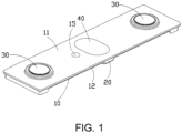
FIG. 1 is a schematic structural view illustrating a battery cover plate assembly according to an exemplary embodiment. -
FIG. 2 is a schematic structural cross-sectional view illustrating a portion the battery cover plate assembly according to an exemplary embodiment. -
FIG. 3 is a schematic structural view illustrating a cover plate of the battery cover plate assembly according to an exemplary embodiment. -
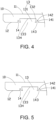
FIG. 4 is a schematic structural cross-sectional view illustrating a portion of the cover plate of the battery cover plate assembly according to the first exemplary embodiment. -
FIG. 5 is a schematic structural cross-sectional view illustrating a portion of the cover plate of the battery cover plate assembly according to the second exemplary embodiment. -
FIG. 6 is a schematic structural cross-sectional view illustrating a portion of the cover plate of the battery cover plate assembly according to the third exemplary embodiment. -
FIG. 7 is a schematic structural cross-sectional view illustrating a portion of the cover plate of the battery cover plate assembly according to the fourth exemplary embodiment. -
FIG. 8 is a schematic structural view illustrating an insulating piece of the battery cover plate assembly according to an exemplary embodiment. -
FIG. 9 is a schematic structural view illustrating a portion of the insulating piece of the battery cover plate assembly according to an exemplary embodiment. -
FIG. 10 is a schematic structural view illustrating a battery according to an exemplary embodiment. -
FIG. 11 is a schematic flow chart of a manufacturing method of a battery cover plate assembly according to an exemplary embodiment. - The technical solutions in the exemplary embodiments of the disclosure will be described clearly and explicitly in conjunction with the drawings in the exemplary embodiments of the disclosure. The description proposed herein is just the exemplary embodiments for the purpose of illustrations only, not intended to limit the scope of the disclosure, so it should be understood that and various modifications and variations could be made thereto without departing from the scope of the disclosure.
- In the description of the present disclosure, unless otherwise specifically defined and limited, the terms "first", "second" and the like are only used for illustrative purposes and are not to be construed as expressing or implying a relative importance. The term "plurality" is two or more. The term "and/or" includes any and all combinations of one or more of the associated listed items.
- In particular, a reference to "the" object or "a" and "an" object is intended to denote also one of a possible plurality of such objects. Unless otherwise defined or described, the terms "connect", "fix" should be broadly interpreted, for example, the term "connect" can be "fixedly connect", "detachably connect", "integrally connect", "electrically connect" or "signal connect". The term "connect" also can be "directly connect" or "indirectly connect via a medium". For the persons skilled in the art, the specific meanings of the abovementioned terms in the present disclosure can be understood according to the specific situation.
- Further, in the description of the present disclosure, it should be understood that spatially relative terms, such as "above", "below" "inside", "outside" and the like, are described based on orientations illustrated in the figures, but are not intended to limit the exemplary embodiments of the present disclosure.
- In the context, it should also be understood that when an element or features is provided "outside" or "inside" of another element(s), it can be directly provided "outside" or "inside" of the other element, or be indirectly provided "outside" or "inside" of the another element(s) by an intermediate element.
- An embodiment of the disclosure includes a battery cover plate assembly. With reference to
FIG. 1 to FIG. 9 , the battery cover plate assembly includes acover plate 10 provided with a first connection portion and aninsulating piece 20 disposed on one side of thecover plate 10. Theinsulating piece 20 is provided with a second connection portion, and the first connection portion is connected to the second connection portion. One of the first connection portion and the second connection portion is amounting hole 13 and the other one is aprotrusion 21, and theprotrusion 21 is in an interference fit with themounting hole 13. An area of anopening 133 of themounting hole 13 is less than a maximum area of a cross section of themounting hole 13, and theprotrusion 21 is inserted into themounting hole 13 through theopening 133 of themounting hole 13. - The battery cover plate assembly provided by an embodiment of the disclosure includes the
cover plate 10 and theinsulating piece 20, and thecover plate 10 and theinsulating piece 20 are connected to each other through the first connection portion and the second connection portion. By arranging one of the first connection portion and the second connection portion as themounting hole 13 and the other one as theprotrusion 21 and arranging theprotrusion 21 and themounting hole 13 to be in an interference fit, thecover plate 10 and theinsulating piece 20 may be reliably fixed. The area of the opening 133 of themounting hole 13 is less than the maximum area of the cross section of themounting hole 13, that is, the area of the opening 133 of themounting hole 13 is relatively small. In this way, the connection stability between theprotrusion 21 and themounting hole 13 may be further improved, the connection stability between thecover plate 10 and theinsulating piece 20 is ensured, and the safe use performance of the battery cover plate assembly is thereby improved. - It should be noted that the
insulating piece 20 is disposed on one side of thecover plate 10. That is, at least a portion of theinsulating piece 20 may be disposed above thecover plate 10, or at least a portion of theinsulating piece 20 may be disposed below thecover plate 10, so as to insulate and protect thecover plate 10. In order to ensure the insulation safety performance of thecover plate 10, it is necessary to ensure the connection stability between thecover plate 10 and theinsulating piece 20. In this embodiment, the connection stability between thecover plate 10 and theinsulating piece 20 may be ensured by the interference fit between theprotrusion 21 and themounting hole 13. Further, the area of the opening 133 of themounting hole 13 is less than the area of at least a portion of the inner space of themounting hole 13. On the basis of the interference fit between theprotrusion 21 and themounting hole 13, theopening 133 of themounting hole 13 may further limit theprotrusion 21, as such, it is ensured that theprotrusion 21 and themounting hole 13 are reliably fixed. - A cross section of the mounting
hole 13 may be treated as a cross section perpendicular to the extending direction of the mountinghole 13, and the mountinghole 13 may have a plurality of cross sections. The area of theopening 133 of the mountinghole 13 is less than the maximum area of the cross section of the mountinghole 13. That is, the cross-sectional area of at least a portion of the inner space of the mountinghole 13 is greater than the area of theopening 133. For instance, the opening of the mountinghole 13 is a circular hole, and the inner space of the mountinghole 13 may be a cylinder, and in this case, the area of the opening of the mountinghole 13 may be less than the cross-sectional area of the cylinder. Alternatively, the opening of the mountinghole 13 is a circular hole, and the inner space of the mountinghole 13 may be a frustum, and in this case, the area of the opening of the mountinghole 13 may be less than the cross-sectional area of at least a portion of the frustum. Alternatively, the opening of the mountinghole 13 is a circular hole, and the inner space of the mountinghole 13 may be a cylinder and a frustum, and in this case, the area of the opening of the mountinghole 13 may be less than the cross-sectional area of at least a portion of the cylinder and the frustum. Certainly, it is not excluded that the inner space of the mountinghole 13 is an irregular space, as long as it can be ensured that the area of the opening of the mountinghole 13 can be less than the cross-sectional area of at least a portion of the inner space of the mountinghole 13. In this embodiment, it is emphasized that on the basis of the interference fit between theprotrusion 21 and the mountinghole 13, theopening 133 of the mountinghole 13 may further limit theprotrusion 21. As such, it is ensured that theprotrusion 21 and the mountinghole 13 are reliably fixed. - The opening of the mounting
hole 13 may be treated as an end port of the mountinghole 13, that is, an end surface of the mounting hole. The orthographic projection of theopening 133 of the mountinghole 13 and the orthographic projection of mountinghole 13 towards thecover plate 10 respectively are a first projection and a second projection, and an area of the first projection is less than an area of the second projection. That is, the maximum circumferential area of the mountinghole 13 may be larger than the area of theopening 133 of the mountinghole 13. - In an embodiment, with reference to
FIG. 4 , thecover plate 10 includes anupper surface 11 and alower surface 12, and theupper surface 11 and thelower surface 12 are disposed opposite to each other. - In an embodiment, the insulating
piece 20 may be disposed on theupper surface 11 of thecover plate 10, so as to achieve insulation protection for theupper surface 11 of thecover plate 10. - In an embodiment, as shown in
FIG. 1 andFIG. 2 , the insulatingpiece 20 may be disposed on thelower surface 12, so as to achieve insulation protection for thelower surface 12 of thecover plate 10. - In an embodiment, the area of the
opening 133 of the mountinghole 13 is less than the area of a bottom 134 of the mountinghole 13. Thebottom 134 of the mountinghole 13 is the end of the mountinghole 13 away from theopening 133 of the mountinghole 13, and theprotrusion 21 is inserted into the mountinghole 13 through theopening 133 of the mountinghole 13. That is, theopening 133 of the mountinghole 13 is the end port through which theprotrusion 21 is inserted into the mountinghole 13, and the area of theopening 133 of the mountinghole 13 is less than the area of the bottom 134 of the mountinghole 13. On the basis of ensuring the interference fit between theprotrusion 21 and the mountinghole 13, theopening 133 of the mountinghole 13 may further limit and fix theprotrusion 21. As such, it is ensured that theprotrusion 21 and the mountinghole 13 are reliably fixed. The problem of loose connection between the insulatingpiece 20 and thecover plate 10 is prevented from occurring after the battery cover plate assembly is used for a long time. - It should be noted that the mounting
hole 13 may be a blind hole, and in this case, thebottom 134 of the mountinghole 13 may be the bottom wall of the mountinghole 13. The mountinghole 13 may be a through hole, and in this case, thebottom 134 of the mountinghole 13 may be another opening of the mountinghole 13. - In an embodiment, the mounting
hole 13 includes anexpansion segment 131, and theexpansion segment 131 has theopening 133 of the mountinghole 13. The area of the cross section of theexpansion segment 131 gradually increases in a direction from theopening 133 of the mountinghole 13 towards thebottom 134 of the mountinghole 13. Therefore, during the process of inserting theprotrusion 21 into theexpansion segment 131 from theopening 133, theprotrusion 21 may shrink first and then gradually expand, so that the interference fit between theprotrusion 21 and the mountinghole 13 is ensured, and theopening 133 with a smaller area can reliably hold theprotrusion 21. In this way, theprotrusion 21 and the mountinghole 13 are reliably matched, so that the problem of loose connection of the battery cover plate assembly after long-term use is prevented from occurring. - In an embodiment, as shown in
FIG. 4 , the mountinghole 13 further includes astraight hole segment 132. Thestraight hole segment 132 communicates with one end of theexpansion segment 131 away from theopening 133 of theexpansion segment 131, and the area of the cross section of thestraight hole segment 131 is consistent in a direction from one end of thestraight hole segment 132 connected to theexpansion segment 131 towards thebottom 134 of the mountinghole 13. In this way, thestraight hole segment 132 may be easily formed, and a portion of theprotrusion 21 may be easily located in thestraight hole segment 132, so as to ensure that the protrusion is reliably matched with the mountinghole 13. - With reference to
FIG. 4 , the mountinghole 13 may be formed by thestraight hole segment 132 and theexpansion segment 131, and theprotrusion 21 may gradually extend into thestraight hole segment 132 from theexpansion segment 131. In this way, the protrusion and the mountinghole 13 may be reliably matched, so as to ensure the reliable connection between the insulatingpiece 20 and thecover plate 10. - In an embodiment, the
expansion segment 131 is a frustum hole segment, and thestraight hole segment 132 is a cylindrical hole segment. In this way, the mountinghole 13 may be easily formed, and it is ensured that the mountinghole 13 may reliably fix theprotrusion 21. The insulatingpiece 20 is thus ensured to be stably connected to thecover plate 10, so that the problem of loose connection of the battery cover plate assembly after long-term use is prevented from occurring. - In an embodiment, an included angle between a hole wall of the
expansion segment 131 and a hole wall of thestraight hole segment 132 is 135° to 179°. As such, the extending tendency of theexpansion segment 131 from thestraight hole segment 132 to theopening 133 of theexpansion segment 131 is a gradual shrinking process. Therefore, on the basis of the interference fit between theprotrusion 21 and the mountinghole 13, theopening 133 of theexpansion segment 131 may also reliably clamp theprotrusion 21. - The included angle between the hole wall of the
expansion segment 131 and the hole wall of thestraight hole segment 132 may be 135°, 136°, 140°, 145°, 150°, 155°, 156°, 160°, 165°, 170°, 175°, 176°, 178°, or 179° and so on. - In an embodiment, the
protrusion 21 includes an elastic portion, and a portion of theprotrusion 21 is located in thestraight hole segment 132. Therefore, a relatively large portion of theprotrusion 21 may extend into the mountinghole 13, so that the fixing performance of theprotrusion 21 is ensured. - In an embodiment, at least part of a wall surface of the
straight hole segment 131 is spaced apart from theprotrusion 21. As such, it is ensured that theprotrusion 21 may be fully arranged in the mountinghole 13, and a certain buffer space is provided. Therefore, after the battery cover plate assembly is used for a long time, even if theprotrusion 21 is deformed, the mountinghole 13 may still be prevented from being excessively squeezed. - In an embodiment, as shown in
FIG. 5 to FIG. 7 , the mountinghole 13 may be an expanded structure as a whole. That is, the cross-sectional area of the expanded structure gradually increases in the direction from theopening 133 of the mountinghole 13 towards thebottom 134 of the mountinghole 13, and theprotrusion 21 may thus be reliably fixed. The protrusion is generally embedded in the mountinghole 13 in an upside-down manner, so that theprotrusion 21 and the mountinghole 13 may be reliably matched. The expanded structure may be a frustum as a whole, or the expanded structure may be an irregular structure with structural changes, which is not limited herein. - In an embodiment, the
cover plate 10 is a metal piece, the insulatingpiece 20 is a plastic piece, the first connection portion is the mountinghole 13, the second connection portion is theprotrusion 21, and theprotrusion 21 is in an interference fit with the mountinghole 13, so that thecover plate 10 and the insulatingpiece 20 are reliably fixed. The insulating part is a plastic piece and can be formed intoprotrusions 21 with different structures by injection molding. Thecover plate 10 is a metal piece, which is relatively difficult to form. The mountinghole 13 is provided on the metal piece, so that the deformation of the mountinghole 13 caused by theprotrusion 21 may be prevented from occurring, and the stability of the structure is thereby ensured. - In an embodiment, the
cover plate 10 is a metal piece, the first connection portion is the mountinghole 13, and the mountinghole 13 is formed by stamping. In this way, the mountinghole 13 may be easily manufactured, and the structural strength of thecover plate 10 is improved, that is, the mountinghole 13 formed by stamping may act as a reinforcing structure. - In an embodiment, with reference to
FIG. 4 to FIG. 7 together, the mountinghole 13 is a blind hole, and the area of theopening 133 of the mountinghole 13 is less than the area of the bottom 134 of the mountinghole 13. Since the side wall of the mountinghole 13 is arranged to be slope-shaped, the structural strength of thecover plate 10 is prevented from being affected by the mountinghole 13. - In an embodiment, as shown in
FIG. 2 , the top end of theprotrusion 21 is spaced apart from thebottom 134 of the mountinghole 13, so that theprotrusion 21 can be mounted in place. Further, the problem of the mountinghole 13 being excessively squeezed caused by the deformation of theprotrusion 21 after long-term use may be prevented from occurring. - In an embodiment, the distance between the top end of the
protrusion 21 and thebottom 134 of the mountinghole 13 is 0.01mm to 1mm. Since theprotrusion 21 is ensured to be mounted in place, theprotrusion 21 may also be deformed and thus squeezes the mountinghole 13 after long-term use. - The distance between the top end of the
protrusion 21 and thebottom 134 of the mountinghole 13 may be 0.01mm, 0.05mm, 0.1mm, 0.2mm, 0.3mm, 0.4mm, 0.5mm, 0.6mm, 0.7mm, 0.8mm, 0.9mm, or 1mm and so on. - In an embodiment, the mounting
hole 13 is a circumferentially closed hole, so that theprotrusion 21 can be reliably matched with the mountinghole 13, theprotrusion 21 and the mountinghole 13 have a reliable contact area, and the mountinghole 13 may be easily formed. - In some embodiments, the mounting
hole 13 may be a circumferentially non-closed hole. - In an embodiment, as shown in
FIG. 9 , an upper portion of theprotrusion 21 is provided with aguide surface 212, so that theprotrusion 21 extends into the mountinghole 13 through theguide surface 212. Therefore, theprotrusion 21 may easily extend into the mountinghole 13, so the assembly efficiency of theprotrusion 21 and the mountinghole 13 is improved, and the assembly efficiency of the battery cover plate assembly is also improved. - In an embodiment, an extension line of the
guide surface 212 from a bottom end to a top end is a curve or a straight line. That is, the line formed by the longitudinal section of theguide surface 212 may be a straight line or a curved line. On the basis of convenient processing, theprotrusion 21 may easily extends into the mountinghole 13, and the assembly efficiency of theprotrusion 21 and the mountinghole 13 is thereby improved. - It should be noted that the
guide surface 212 may be formed on part of the circumferential outer side of theprotrusion 21, or theguide surface 212 may be formed on the entire circumferential outer side of theprotrusion 21. The purpose of the arrangement of theguide surface 212 is to allow theprotrusion 21 to easily extend into the mountinghole 13, to make the edge of theprotrusion 21 smooth, and to avoid damage to related structures when theprotrusion 21 extends into the mountinghole 13. - In an embodiment, an adhesive layer is arranged between the
protrusion 21 and the mountinghole 13. In this way, theprotrusion 21 and the mountinghole 13 may achieve second connection through the adhesive layer, theprotrusion 21 and the mountinghole 13 are ensured to be stably connected, and the connection stability between thecover plate 10 and the insulatingmember 20 is further improved. - The adhesive layer between the
protrusion 21 and the mountinghole 13 may be the glue in the related art, which is not limited herein. The adhesive layer may be solid adhesive, and the adhesive layer may also be liquid adhesive, which is not limited herein. - In an embodiment, an adhesive layer is provided on the hole wall of the mounting
hole 13 to allow theprotrusion 21 to be connected to the adhesive layer after being inserted into the mountinghole 13. In this way, theprotrusion 21 may be easily arranged, and it is ensured that theprotrusion 21 and the mountinghole 13 may be reliably connected through the adhesive layer. - In some embodiments, the
protrusion 21 is provided with the adhesive layer, so that after theprotrusion 21 is inserted into the mountinghole 13, theprotrusion 21 may form a connection with the hole wall of the mountinghole 13. - In an embodiment, the adhesive layer is provided on the side wall of the mounting
hole 13, so that after theprotrusion 21 is inserted into the mountinghole 13, the side wall of theprotrusion 21 may be reliably connected to the side wall of the mountinghole 13, and theprotrusion 21 and the mountinghole 13 are thus ensured to be reliably connected. - In some embodiments, an adhesive layer may be provided on the bottom wall of the mounting
hole 13, so that the top end of theprotrusion 21 and the bottom wall of the mountinghole 13 may be connected to each other through the adhesive layer. - In an embodiment, as shown in
FIG. 4 to FIG. 6 , thecover plate 10 or the insulatingpiece 20 is provided with agroove 14, and thegroove 14 surrounds the mountinghole 13, so that thegroove 14 and the mountinghole 13 are spaced apart. Besides, thegroove 14 may be a process hole to assist the formation of the mountinghole 13, or thegroove 14 may serve as a buffer structure. In this way, the solid structure between thegroove 14 and the mountinghole 13 can form a buffer, and the connection stability between theprotrusion 21 and the mountinghole 13 is thus improved. - In an embodiment, with reference to
FIG. 2 , anotch 143 of thegroove 14 and theopening 133 of the mountinghole 13 may be on the same plane. The distance between thenotch 143 of thegroove 14 and theopening 133 of the mountinghole 13 is 0.2mm to 1mm, and/or the distance between thegroove 14 and the mountinghole 13 is 0.2mm to 1mm. Through the above arrangement, it is avoided that the distance between thenotch 143 of thegroove 14 and theopening 133 of the mountinghole 13 is excessively close to cause the structure to become less stable, and it is also avoided that the distance between thenotch 143 of thegroove 14 and theopening 133 of the mountinghole 13 is excessively long, which is inconvenient for structural molding. - The distance between the
notch 143 of thegroove 14 and theopening 133 of the mountinghole 13 may be 0.2mm, 0.25mm, 0.3mm, 0.4mm, 0.5mm, 0.6mm, 0.7mm, 0.8mm, 0.9mm, 0.95mm, or 1mm and so on. - The distance between the
groove 14 and the mountinghole 13 may be further treated as the physical thickness between the mountinghole 13 and thegroove 14. - The distance between the
groove 14 and the mountinghole 13 may be 0.2mm, 0.25mm, 0.3mm, 0.4mm, 0.5mm, 0.6mm, 0.7mm, 0.8mm, 0.9mm, 0.95mm, or 1mm and so on. - In an embodiment, the depth of the
groove 14 is not greater than the depth of the mountinghole 13, so that thegroove 14 may assist the forming of the mountinghole 13, and thegroove 14 is also prevented from being excessively large to affect the structural strength. - In an embodiment, the difference between the depth of the mounting
hole 13 and the depth of thegroove 14 is 0mm to 0.5mm. In this way, it is ensured that the depth of thegroove 14 is not greater than the depth of the mountinghole 13, and the problem of weakening the structural strength caused by an excessively large difference between the depth of the mountinghole 13 and the depth of thegroove 14 may also be prevented from occurring. - The difference between the depth of the mounting
hole 13 and the depth of thegroove 14 may be 0, 0.05mm, 0.1mm, 0.2mm, 0.3mm, 0.4mm, 0.45mm, or 0.5mm, and so on. - In an embodiment, the
groove 14 is formed by stamping, so that the mountinghole 13 is provided with theexpansion segment 131. That is, the mountinghole 13 may be formed with the straight hole segment first, and thegroove 14 may be formed later, so that at least part of the straight hole segment forms theexpansion segment 131. - In an embodiment, the depth of the
groove 14 is less than the depth of the mountinghole 13, so that the mountinghole 13 is formed by theexpansion segment 131 and thestraight hole segment 132. That is, the mountinghole 13 may be formed with a larger straight hole segment first, and thegroove 14 may be formed later, so that a portion of the straight hole segment forms theexpansion segment 131, and the rest of the straight hole segment serves as thestraight hole segment 132, as shown inFIG. 4 . - In an embodiment, as shown in
FIG. 4 to FIG. 6 , thegroove 14 includes afirst side wall 141 and asecond side wall 142 opposite to each other. Thefirst side wall 141 is located on the side of thegroove 14 away from the mountinghole 13, thesecond side wall 142 is located on the side of thegroove 14 close to the mountinghole 13, and thesecond side wall 142 is inclined towards the side close to the mountinghole 13 with respect to thefirst side wall 141. As such, in the process of forming thegroove 14, theexpansion segment 131 of the mountinghole 13 may be formed. - With reference to
FIG. 4 , the mountinghole 13 is formed by theexpansion segment 131 and thestraight hole segment 132, and the depth of thegroove 14 is approximately equal to the depth of theexpansion segment 131, so that theexpansion segment 131 can be formed during the process of forming thegroove 14. - With reference to
FIG. 5 , the mountinghole 13 may be approximately theexpansion segment 131, and the depth of thegroove 14 is less than the depth of theexpansion segment 131. The mountinghole 13 may be formed by machining, or a portion of theexpansion segment 131 may be formed in the process of forming thegroove 14. - With reference to
FIG. 6 , the mountinghole 13 is formed by theexpansion segment 131, and the depth of thegroove 14 is approximately equal to the depth of theexpansion segment 13. That is, the depth of thegroove 14 is approximately equal to the depth of the mountinghole 13, so that theexpansion segment 131 may be formed in the process of forming thegroove 14, - With reference to
FIG. 7 , thecover plate 10 may only be provided with mountinghole 13 without thegroove 14, and the mountinghole 13 may be formed by machining. - In an embodiment, as shown in
FIG. 4 , thefirst side wall 141 is substantially perpendicular to the bottom wall of thegroove 14. That is, thefirst side wall 141 may be a straight wall and thesecond side wall 142 may be an inclined wall, so that in the process of forming thegroove 14 by stamping, the excess material may be squeezed towards the mountinghole 13 as much as possible, so the inclined wall may be formed. Through the arrangement of the straight wall, the extrusion of the material to the side away from the mountinghole 13 may be avoided as much as possible, and it can also be ensured that the material is extruded to the side close to the mountinghole 13 to form an inclined wall. - The depth of the
groove 14 is less than the depth of the mountinghole 13, so that whengroove 14 is stamped, the mountinghole 13 may formed by theexpansion segment 131 and thestraight hole segment 132. That is, a larger straight hole segment may be formed first, and thegroove 14 may be formed later, so that a portion of the straight hole segment forms theexpansion segment 131, and the rest of the straight hole segment serves as thestraight hole segment 132. - In an embodiment, a plurality of first connection portions are provided and a plurality of second connection portions are provided. The first connection portions and the second connection portions are connected to each other, so the
cover plate 10 and the insulatingpiece 20 are reliably connected to each other in this way. - With reference to
FIG. 3 andFIG. 8 , a plurality of mountingholes 13 are provided and a plurality ofprotrusions 21 are provided. Theprotrusions 21 and the mountingholes 13 are connected to each other, so thecover plate 10 and the insulatingpiece 20 are reliably connected to each other in this way. - The
protrusion 21 may be a one-piece structure, that is, theprotrusion 21 may be an integral structure, as shown inFIG. 9 . Alternatively, theprotrusion 21 may include a plurality of independent structures, and the plurality of independent structures are in an interference fit with the mountinghole 13. - In one embodiment, the diameter of the mounting
hole 13 ranges from 2mm to 10mm. This ensures that the mountinghole 13 has a relatively large volume, and the mountinghole 13 is also prevented from being excessively large and occupying too much space, so that only a relatively small space of thecover plate 10 or the insulatingpiece 20 is occupied. The diameter of the largest circumferential outer edge of theprotrusion 21 is larger than the diameter of theopening 133 of the mountinghole 13. That is, the maximum area of the cross section of theprotrusion 21 is larger than the area of theopening 133 of the mountinghole 13, so as to ensure the interference fit between theprotrusion 21 and the mountinghole 13. - In an embodiment, as shown in
FIG. 1 , thecover plate 10 is provided with aliquid injection hole 15 through which the battery can be injected with liquid inside, and theliquid injection hole 15 may be sealed by a sealing structure. - In an embodiment, as shown in
FIG. 1 , the battery cover plate assembly further includes aterminal component 30 and an explosion-proof valve 40. Twoterminal components 30 may be provided, the twoterminal components 30 may be spaced apart from each other on thecover plate 10, and the explosion-proof valve 40 may be located between the twoterminal components 30. - In an embodiment, the battery cover plate assembly is a square battery cover plate assembly.
- An embodiment of the disclosure further provides a battery including the abovementioned battery cover plate assembly.
- A battery provided by an embodiment of the disclosure includes a battery cover plate assembly. The battery cover plate assembly includes the
cover plate 10 and the insulatingpiece 20, and thecover plate 10 and the insulatingpiece 20 are connected to each other through the first connection portion and the second connection portion. By arranging one of the first connection portion and the second connection portion as the mountinghole 13 and the other one as theprotrusion 21 and arranging theprotrusion 21 and the mountinghole 13 to be in an interference fit, thecover plate 10 and the insulatingpiece 20 may be reliably fixed. The area of theopening 133 of the mountinghole 13 is less than the maximum area of the cross section of the mountinghole 13, that is, the area of theopening 133 of the mountinghole 13 is relatively small. In this way, the connection stability between theprotrusion 21 and the mountinghole 13 may be further improved, the connection stability between thecover plate 10 and the insulatingpiece 20 is ensured, and the safe use performance of the battery is thereby improved. - With reference to
FIG. 10 , the battery further includes acasing 50, the battery cover plate assembly is connected to thecasing 50, and thecover plate 10 may be welded to thecasing 50. The battery further includes a cell, and the cell is disposed in the battery cover plate assembly and thecasing 50. The battery may be a quadrangular prismatic battery, that is, a square battery. - The battery includes a cell and an electrolyte, and the battery is the smallest unit capable of performing electrochemical reactions such as charging/discharging. The cell refers to a unit formed by winding or laminating a stacked part, and the stacked part includes a first electrode, a separator, and a second electrode. When the first electrode is a positive electrode, the second electrode is a negative electrode. The polarities of the first electrode and the second electrode may be interchanged.
- In an embodiment, the battery is a laminated battery, which may be conveniently assembled and may further be processed to obtain a battery with a longer length.
- To be specific, the cell is a laminated cell. The cell has first electrode pieces that are stacked on each other, second electrode pieces whose electrical properties are opposite to the first electrode pieces, and diaphragm pieces disposed between the first electrode pieces and the second electrode pieces. Therefore, multiple pairs of the first electrode pieces and the second electrode pieces are stacked to form the laminated cell.
- Optionally, the battery may be a wound battery. That is, the first electrode pieces, the second electrode pieces whose electrical properties are opposite to the first electrode pieces, and the diaphragm pieces disposed between the first electrode pieces and the second electrode pieces are wound to obtain a wound cell.
- An embodiment of the disclosure further provides a battery apparatus including the abovementioned battery.
- A battery of a battery apparatus provided by an embodiment of the disclosure includes a battery cover plate assembly. The battery cover plate assembly includes the
cover plate 10 and the insulatingpiece 20, and thecover plate 10 and the insulatingpiece 20 are connected to each other through the first connection portion and the second connection portion. By arranging one of the first connection portion and the second connection portion as the mountinghole 13 and the other one as theprotrusion 21 and arranging theprotrusion 21 and the mountinghole 13 to be in an interference fit, thecover plate 10 and the insulatingpiece 20 may be reliably fixed. The area of theopening 133 of the mountinghole 13 is less than the maximum area of the cross section of the mountinghole 13, that is, the area of theopening 133 of the mountinghole 13 is relatively small. In this way, the connection stability between theprotrusion 21 and the mountinghole 13 may be further improved, the connection stability between thecover plate 10 and the insulatingpiece 20 is ensured, and the safe use performance of the battery apparatus is thereby improved. - In an embodiment, the battery apparatus is a battery module or a battery pack.
- The battery module includes a plurality of batteries, and the battery module may further include end plates and side plates. The end plates and the side plates are configured to secure a plurality of batteries.
- Note that a plurality of batteries may be formed into a battery module and then may be arranged in a battery box, and the plurality of batteries may be secured by the end plates and the side plates. The plurality of batteries may be directly disposed in the battery box, that is, the plurality of batteries are not required to be arranged into groups, and the end plates and the side plates may then be removed.
- An embodiment of the disclosure further provides a manufacturing method of a battery cover plate assembly. With reference to
FIG. 11 , the manufacturing method of the battery cover plate assembly includes the following step. - In S101, the insulating
piece 20 is arranged on one side of thecover plate 10, so that the first connection portion of thecover plate 10 is connected to the second connection portion of the insulatingpiece 20. - One of the first connection portion and the second connection portion is a mounting
hole 13 and the other one is aprotrusion 21, and theprotrusion 21 is in an interference fit with the mountinghole 13. An area of anopening 133 of the mountinghole 13 is less than a maximum area of a cross section of the mountinghole 13, and theprotrusion 21 is inserted into the mountinghole 13 through theopening 133 of the mountinghole 13. - In the manufacturing method of the battery cover plate assembly provided by an embodiment of the disclosure, the
cover plate 10 and the insulatingpiece 20 are connected to each other through the first connection portion and the second connection portion. By arranging one of the first connection portion and the second connection portion as the mountinghole 13 and the other one as theprotrusion 21 and arranging theprotrusion 21 and the mountinghole 13 to be in an interference fit, thecover plate 10 and the insulatingpiece 20 may be reliably fixed. The area of theopening 133 of the mountinghole 13 is less than the maximum area of the cross section of the mountinghole 13, that is, the area of theopening 133 of the mountinghole 13 is relatively small. In this way, the connection stability between theprotrusion 21 and the mountinghole 13 may be further improved, the connection stability between thecover plate 10 and the insulatingpiece 20 is ensured, and the safe use performance of the battery cover plate assembly is thereby improved. - In an embodiment, the manufacturing method of the battery cover plate assembly further includes the following step. An adhesive layer is arranged between the
protrusion 21 and the mountinghole 13. In this way, theprotrusion 21 and the mountinghole 13 may achieve second connection through the adhesive layer, theprotrusion 21 and the mountinghole 13 are ensured to be stably connected, and the connection stability between thecover plate 10 and the insulatingmember 20 is further improved. - In an embodiment, arranging the adhesive layer between the
protrusion 21 and the mountinghole 13 further includes the following step. After the adhesive layer is arranged on at least one of theprotrusion 21 and the mountinghole 13, theprotrusion 21 is inserted into the mountinghole 13, so that theprotrusion 21 and the mountinghole 13 may be reliably connected. - Before the
cover plate 10 is connected to the insulatingpiece 20, the adhesive layer is arranged on theprotrusion 21, and then theprotrusion 21 is inserted into the mountinghole 13, so that the adhesive layer is connected to both theprotrusion 21 and the mountinghole 13. Alternatively, before thecover plate 10 is connected to the insulatingpiece 20, the adhesive layer is arranged on the hole wall of the mountinghole 13, and then theprotrusion 21 is inserted into the mountinghole 13, so that the adhesive layer is connected to both theprotrusion 21 and the mountinghole 13. Alternatively, before thecover plate 10 is connected to the insulatingpiece 20, the adhesive layer is arranged on theprotrusion 21, the adhesive layer is arranged on the hole wall of the mountinghole 13, and then theprotrusion 21 is inserted into the mountinghole 13, so that the adhesive layer is connected to both theprotrusion 21 and the mountinghole 13. - In an embodiment, after the
protrusion 21 is inserted into the mountinghole 13, the adhesive layer is injected between theprotrusion 21 and the mountinghole 13, so that theprotrusion 21 and the mountinghole 13 are reliably connected. - After the
protrusion 21 is inserted into the mountinghole 13, theprotrusion 21 and the mountinghole 13 achieve an interference fit. A glue injection hole may be provided on theprotrusion 21, and the glue injection hole is subsequently injected into theprotrusion 21 and the mountinghole 13, so that an adhesive layer is connected to both theprotrusion 21 and the mountinghole 13. - In an embodiment, forming the mounting
hole 13 on thecover plate 10 or the insulatingpiece 20 includes the following. The area of theopening 133 of the mountinghole 13 is allowed to be less than the area of the bottom 134 of the mountinghole 13. Herein, thebottom 134 of the mountinghole 13 is the end of the mountinghole 13 away from theopening 133 of the mountinghole 13, and theprotrusion 21 is inserted into the mountinghole 13 through theopening 133 of the mountinghole 13. That is, theopening 133 of the mountinghole 13 is the end port through which theprotrusion 21 is inserted into the mountinghole 13, and the area of theopening 133 of the mountinghole 13 is less than the area of the bottom 134 of the mountinghole 13. On the basis of ensuring the interference fit between theprotrusion 21 and the mountinghole 13, theopening 133 of the mountinghole 13 may further limit and fix theprotrusion 21. As such, it is ensured that theprotrusion 21 and the mountinghole 13 are reliably fixed. The problem of loose connection between the insulatingpiece 20 and thecover plate 10 is prevented from occurring after the battery cover plate assembly is used for a long time. - In an embodiment, allowing the area of the
opening 133 of the mountinghole 13 to be less than the area of the bottom 134 of the mountinghole 13 includes the following. The straight hole segment is formed on thecover plate 10 or the insulatingpiece 20. Thegroove 14 is formed on thecover plate 10 or the insulatingpiece 20, and the side wall of thegroove 14 close to the straight hole segment is arranged to be inclined, so that at least a portion of the straight hole segment is pressed. Therefore, at least part of the straight hole segment may be formed into a structure that gradually expands from the opening to the bottom, so as to ensure the reliable and fixed connection between theprotrusion 21 and the mountinghole 13. - In an embodiment, the straight hole segment and the
groove 14 are stamped and formed in sequence, and a portion of the straight hole segment is pressed during the stamping process of thegroove 14, so as to form the mountinghole 13 formed by thestraight hole segment 132 and theexpansion segment 131. By stamping and forming the straight hole segment and thegroove 14 in sequence, a simple process is provided, and theexpansion segment 131 may be formed during the process of forming thegroove 14, so the forming efficiency of the mountinghole 13 is thereby improved. - The
groove 14 formed by stamping includes thefirst side wall 141 and thesecond side wall 142 opposite to each other. Thefirst side wall 141 is located on the side of thegroove 14 away from the mountinghole 13, thesecond side wall 142 is located on the side of thegroove 14 close to the mountinghole 13, and thesecond side wall 142 is inclined towards the side close to the mountinghole 13 with respect to thefirst side wall 141. As such, in the process of forming thegroove 14, theexpansion segment 131 of the mountinghole 13 may be formed. - In an embodiment, the manufacturing method of the battery cover plate assembly forms the abovementioned battery cover plate assembly.
- It should be noted that for the related structures involved in the manufacturing method of the battery cover plate assembly in this embodiment, reference may be made to description of the abovementioned battery cover plate assembly, for example, the formed mounting
hole 13 may be a blind hole, etc., and description thereof is not repeated herein. - Other embodiments of the disclosure will be apparent to those skilled in the art from consideration of the specification and practice of the disclosure disclosed herein. The disclosure is intended to cover any variations, uses or adaptations of the disclosure. These variations, uses, or adaptations follow the general principles of the disclosure and include common general knowledge or conventional technical means in the art that are not disclosed in the present disclosure.
Claims (30)
- A battery cover plate assembly, comprising:a cover plate (10), wherein a first connection portion is arranged on the cover plate (10); andan insulating piece (20), wherein the insulating piece (20) is disposed on one side of the cover plate (10), the insulating piece (20) is provided with a second connection portion, and the first connection portion is connected to the second connection portion,wherein one of the first connection portion and the second connection portion is a mounting hole (13) and the other one is a protrusion (21), the protrusion (21) is in an interference fit with the mounting hole (13), an area of an opening (133) of the mounting hole (13) is less than a maximum area of a cross section of the mounting hole (13), and the protrusion (21) is inserted into the mounting hole (13) through the opening (133) of the mounting hole (13).
- The battery cover plate assembly according to claim 1, wherein the area of the opening (133) of the mounting hole (13) is less than an area of a bottom (134) of the mounting hole (13), and the bottom (134) of the mounting hole (13) is one end of the mounting hole (13) away from the opening (133) of the mounting hole (13).
- The battery cover plate assembly according to claim 2, wherein the mounting hole (13) comprises an expansion segment (131), the expansion segment (131) has the opening (133) of the mounting hole (13), and an area of a cross section of the expansion segment (131) gradually increases in a direction from the opening (133) of the mounting hole (13) towards the bottom (134) of the mounting hole (13).
- The battery cover plate assembly according to claim 3, wherein the mounting hole (13) further comprises a straight hole segment (132), the straight hole segment (132) communicates with one end of the expansion segment (131) away from the opening (133) of the expansion segment (131), and an areas of a cross section of the straight hole segment (132) is consistent in a direction from one end of the straight hole segment (132) connected to the expansion segment (131) towards the bottom (134) of the mounting hole (13).
- The battery cover plate assembly according to claim 4, wherein the expansion segment (131) is a frustum hole segment, and the straight hole segment (132) is a cylindrical hole segment.
- The battery cover plate assembly according to claim 5, wherein an included angle between a hole wall of the expansion segment (131) and a hole wall of the straight hole segment (132) is 135° to 179°.
- The battery cover plate assembly according to claim 4, wherein the protrusion (21) comprises an elastic portion, and a portion of the protrusion (21) is located in the straight hole segment (132),
wherein at least part of a wall surface of the straight hole segment (132) is spaced apart from the protrusion (21). - The battery cover plate assembly according to claim 1, wherein the cover plate (10) is a metal piece, the insulating piece (20) is a plastic piece, the first connection portion is the mounting hole (13), and the second connection portion is the protrusion (21).
- The battery cover plate assembly according to claim 8, wherein the mounting hole (13) is formed by stamping.
- The battery cover plate assembly according to claim 1, wherein the mounting hole (13) is a blind hole, and the area of the opening (133) of the mounting hole (13) is less than the area of the bottom (134) of the mounting hole (13).
- The battery cover plate assembly according to claim 10, wherein a top end of the protrusion (21) is spaced apart from the bottom (134) of the mounting hole (13).
- The battery cover plate assembly according to claim 11, wherein a distance between the top end of the protrusion (21) and the bottom (134) of the mounting hole (13) is 0.01mm to 1mm.
- The battery cover plate assembly according to claim 1, wherein the mounting hole (13) is a circumferentially closed hole.
- The battery cover plate assembly according to claim 1, wherein an upper portion of the protrusion (21) is provided with a guide surface, so that the protrusion (21) extends into the mounting hole (13) through the guide surface.
- The battery cover plate assembly according to claim 14, wherein an extension line of the guide surface from a bottom end to a top end is a curve or a straight line.
- The battery cover plate assembly according to claim 1, wherein an adhesive layer is arranged between the protrusion (21) and the mounting hole (13).
- The battery cover plate assembly according to any one of claims 1-16, wherein the cover plate (10) or the insulating piece (20) is provided with a groove (14), and the groove (14) surrounds the mounting hole (13).
- The battery cover plate assembly according to claim 17, wherein a distance between a notch (143) of the groove (14) and the opening (133) of the mounting hole (13) is 0.2mm to 1mm, and/or a distance between the groove (14) and the mounting hole (13) is 0.2mm to 1mm.
- The battery cover plate assembly according to claim 17, wherein a depth of the groove (14) is not greater than a depth of the mounting hole (13), or a difference between the depth of the mounting hole (13) and the depth of the groove (14) is 0mm to 0.5mm.
- The battery cover plate assembly according to claim 18 or 19, wherein the groove (14) comprises a first side wall (141) and a second side wall (142) opposite to each other, the first side wall (141) is located on one side of the groove (14) away from the mounting hole (13), the second side wall (142) is located on one side of the groove (14) close to the mounting hole (13), and the second side wall (142) is inclined towards the side close to the mounting hole (13) relative to the first side wall (141).
- The battery cover plate assembly according to claim 20, wherein the first side wall (141) is substantially perpendicular to a bottom wall of the groove (14).
- The battery cover plate assembly according to any one of claims 1-16, wherein a plurality of first connection portions are provided, and a plurality of second connection portions are provided.
- The battery cover plate assembly according to any one of claims 1-16, wherein a diameter of the mounting hole (13) ranges from 2mm to 10mm.
- A battery, comprising the battery cover plate assembly according to any one of claims 1-23.
- A manufacturing method of a battery cover plate assembly, comprising:arranging an insulating piece (20) on one side of a cover plate (10), so that a first connection portion of the cover plate (10) is connected to a second connection portion of the insulating piece (20),wherein one of the first connection portion and the second connection portion is a mounting hole (13) and the other one is a protrusion (21), the protrusion (21) is in an interference fit with the mounting hole (13), an area of an opening (133) of the mounting hole (13) is less than a maximum area of a cross section of the mounting hole (13), and the protrusion (21) is inserted into the mounting hole (13) through the opening (133) of the mounting hole (13).
- The manufacturing method of the battery cover plate assembly according to claim 25, further comprising:
arranging an adhesive layer between the protrusion (21) and the mounting hole (13). - The manufacturing method of the battery cover plate assembly according to claim 26, wherein arranging the adhesive layer between the protrusion (21) and the mounting hole (13) comprises:inserting the protrusion (21) into the mounting hole (13) after arranging the adhesive layer on at least one of the mounting hole (13) and the protrusion (21); orinjecting the adhesive layer between the protrusion (21) and the mounting hole (13) after inserting the protrusion (21) into the mounting hole (13).
- The manufacturing method of the battery cover plate assembly according to claim 25, wherein forming the mounting hole (13) on the cover plate (10) or the insulating piece (20) comprises:allowing the area of the opening (133) of the mounting hole (13) to be less than an area of a bottom (134) of the mounting hole (13),wherein the bottom (134) of the mounting hole (13) is one end of the mounting hole (13) away from the opening (133) of the mounting hole (13).
- The manufacturing method of the battery cover plate assembly according to claim 28, wherein allowing the area of the opening (133) of the mounting hole (13) to be less than the area of the bottom (134) of the mounting hole (13) comprises:forming a straight hole segment on the cover plate (10) or the insulating piece (20); andforming a groove (14) on the cover plate (10) or the insulating piece (20) and arranging a side wall of the groove (14) close to the straight hole segment to be inclined, so that at least a portion of the straight hole segment is pressed.
- The manufacturing method of the battery cover plate assembly according to claim 29, wherein stamping and forming the straight hole segment and the groove (14) in sequence and pressing a portion of the straight hole segment during the process of stamping the groove (14), so as to form the mounting hole (13) formed by the straight hole segment (132) and an expansion segment (131).
Applications Claiming Priority (1)
| Application Number | Priority Date | Filing Date | Title |
|---|---|---|---|
| CN202210927978.7A CN115207532A (en) | 2022-08-03 | 2022-08-03 | Battery cover plate assembly, battery and manufacturing method of battery cover plate assembly |
Publications (2)
| Publication Number | Publication Date |
|---|---|
| EP4318748A2 true EP4318748A2 (en) | 2024-02-07 |
| EP4318748A3 EP4318748A3 (en) | 2024-05-22 |
Family
ID=83586644
Family Applications (1)
| Application Number | Title | Priority Date | Filing Date |
|---|---|---|---|
| EP23159861.6A Pending EP4318748A3 (en) | 2022-08-03 | 2023-03-03 | Battery cover plate assembly, battery and manufacturing method of battery cover plate assembly |
Country Status (3)
| Country | Link |
|---|---|
| US (1) | US20240047795A1 (en) |
| EP (1) | EP4318748A3 (en) |
| CN (1) | CN115207532A (en) |
Families Citing this family (5)
| Publication number | Priority date | Publication date | Assignee | Title |
|---|---|---|---|---|
| USD1082662S1 (en) * | 2020-04-17 | 2025-07-08 | Accuma Corporation | Battery cover |
| USD1078602S1 (en) * | 2021-07-06 | 2025-06-10 | Lithiumhub Technologies, Llc | Cover for a battery |
| USD1077747S1 (en) * | 2021-07-06 | 2025-06-03 | Lithiumhub Technologies, Llc | Cover for a battery |
| CN218731333U (en) * | 2022-11-16 | 2023-03-24 | 宁德时代新能源科技股份有限公司 | Cover assembly, battery and electrical device |
| CN116404326B (en) * | 2023-06-08 | 2023-09-05 | 深圳海辰储能控制技术有限公司 | End cover assembly, energy storage device and electric equipment |
Family Cites Families (12)
| Publication number | Priority date | Publication date | Assignee | Title |
|---|---|---|---|---|
| ES2021909A6 (en) * | 1989-11-28 | 1991-11-16 | Union Plastica Ltda | Sprung flange battery tray system. |
| CN206133152U (en) * | 2016-11-09 | 2017-04-26 | 信利半导体有限公司 | Backlight and liquid crystal display module |
| CN114976401B (en) * | 2017-08-30 | 2024-03-29 | 宁德时代新能源科技股份有限公司 | Top cover assembly of secondary battery and secondary battery |
| CN108360737A (en) * | 2017-12-31 | 2018-08-03 | 浙江天仁风管有限公司 | The wallboard of mortise and tenon type assembly |
| CN208955087U (en) * | 2018-10-30 | 2019-06-07 | 宁德时代新能源科技股份有限公司 | Secondary cell |
| CN210369544U (en) * | 2019-05-22 | 2020-04-21 | 泉州市元通科技服务有限公司 | A kind of lightweight environmental protection building board |
| CN209981287U (en) * | 2019-08-15 | 2020-01-21 | 宁德时代新能源科技股份有限公司 | Lid assembly for secondary battery and secondary battery |
| CN110797479A (en) * | 2019-11-15 | 2020-02-14 | 王心力 | Lithium battery cover plate structure |
| CN111140581A (en) * | 2020-01-11 | 2020-05-12 | 苏州炬鸿通讯电脑科技有限公司 | A connection structure of a soft connector and a lower insulating pad based on a buckle structure |
| CN112713342B (en) * | 2020-12-31 | 2023-09-01 | 远景动力技术(江苏)有限公司 | A kind of top cover and its assembly method and square case electric core |
| CN113270695A (en) * | 2021-06-24 | 2021-08-17 | 天能帅福得能源股份有限公司 | Square aluminum-shell battery cover plate |
| CN216161824U (en) * | 2021-09-10 | 2022-04-01 | 厦门海辰新能源科技有限公司 | Top cover assembly and battery |
-
2022
- 2022-08-03 CN CN202210927978.7A patent/CN115207532A/en active Pending
-
2023
- 2023-03-03 EP EP23159861.6A patent/EP4318748A3/en active Pending
- 2023-03-13 US US18/182,404 patent/US20240047795A1/en active Pending
Also Published As
| Publication number | Publication date |
|---|---|
| EP4318748A3 (en) | 2024-05-22 |
| US20240047795A1 (en) | 2024-02-08 |
| CN115207532A (en) | 2022-10-18 |
Similar Documents
| Publication | Publication Date | Title |
|---|---|---|
| EP4318748A2 (en) | Battery cover plate assembly, battery and manufacturing method of battery cover plate assembly | |
| KR101166025B1 (en) | Battery module | |
| US20200136110A1 (en) | Battery module | |
| EP2696429B1 (en) | Compressible core for a wound electrode assembly | |
| EP2913868B1 (en) | Secondary battery and method of manufacturing the same | |
| JP4530333B2 (en) | Sealed battery | |
| EP2958171B1 (en) | Secondary battery | |
| KR101142600B1 (en) | Secondary battery | |
| EP3249668B1 (en) | Electric energy storage device having improved installation structure of internal terminal | |
| KR20100044404A (en) | Secondary battery comprising battery case of improved safety | |
| CN114497904A (en) | Battery assembly method and battery | |
| CN115117524A (en) | Battery and method for manufacturing battery | |
| EP2849248A1 (en) | Rechargeable battery | |
| KR20140101228A (en) | Battery module | |
| KR102275545B1 (en) | Bettery cell and fabricating method of the same | |
| CN109755422B (en) | Power battery top cover component, power battery and battery module | |
| JP2010087170A (en) | Electric storage device | |
| JP4451654B2 (en) | Lithium secondary battery | |
| KR20110035426A (en) | Secondary battery | |
| CN220138648U (en) | Single cell | |
| CN218123575U (en) | Battery cover plate assembly and battery | |
| CN216793949U (en) | Battery and battery pack | |
| CN105531848A (en) | Cap assembly including safety valve having protrusion for blocking leakage path and lithium secondary battery including the cap assembly | |
| CN215377461U (en) | Arc steel casing battery packaging structure and arc battery | |
| CN217691516U (en) | Battery with a battery cell |
Legal Events
| Date | Code | Title | Description |
|---|---|---|---|
| PUAI | Public reference made under article 153(3) epc to a published international application that has entered the european phase |
Free format text: ORIGINAL CODE: 0009012 |
|
| STAA | Information on the status of an ep patent application or granted ep patent |
Free format text: STATUS: REQUEST FOR EXAMINATION WAS MADE |
|
| 17P | Request for examination filed |
Effective date: 20230303 |
|
| AK | Designated contracting states |
Kind code of ref document: A2 Designated state(s): AL AT BE BG CH CY CZ DE DK EE ES FI FR GB GR HR HU IE IS IT LI LT LU LV MC ME MK MT NL NO PL PT RO RS SE SI SK SM TR |
|
| PUAL | Search report despatched |
Free format text: ORIGINAL CODE: 0009013 |
|
| AK | Designated contracting states |
Kind code of ref document: A3 Designated state(s): AL AT BE BG CH CY CZ DE DK EE ES FI FR GB GR HR HU IE IS IT LI LT LU LV MC ME MK MT NL NO PL PT RO RS SE SI SK SM TR |
|
| RIC1 | Information provided on ipc code assigned before grant |
Ipc: H01M 50/593 20210101ALI20240412BHEP Ipc: H01M 50/586 20210101ALI20240412BHEP Ipc: H01M 50/164 20210101ALI20240412BHEP Ipc: H01M 50/159 20210101ALI20240412BHEP Ipc: H01M 50/15 20210101AFI20240412BHEP |