EP4318724A1 - Apparatus and method for manufacturing electrode assembly - Google Patents
Apparatus and method for manufacturing electrode assembly Download PDFInfo
- Publication number
- EP4318724A1 EP4318724A1 EP22936039.1A EP22936039A EP4318724A1 EP 4318724 A1 EP4318724 A1 EP 4318724A1 EP 22936039 A EP22936039 A EP 22936039A EP 4318724 A1 EP4318724 A1 EP 4318724A1
- Authority
- EP
- European Patent Office
- Prior art keywords
- pole pieces
- support portion
- pole piece
- driving
- pole
- Prior art date
- Legal status (The legal status is an assumption and is not a legal conclusion. Google has not performed a legal analysis and makes no representation as to the accuracy of the status listed.)
- Pending
Links
Images

Classifications
-
- H—ELECTRICITY
- H01—ELECTRIC ELEMENTS
- H01M—PROCESSES OR MEANS, e.g. BATTERIES, FOR THE DIRECT CONVERSION OF CHEMICAL ENERGY INTO ELECTRICAL ENERGY
- H01M10/00—Secondary cells; Manufacture thereof
- H01M10/05—Accumulators with non-aqueous electrolyte
- H01M10/058—Construction or manufacture
- H01M10/0585—Construction or manufacture of accumulators having only flat construction elements, i.e. flat positive electrodes, flat negative electrodes and flat separators
-
- H—ELECTRICITY
- H01—ELECTRIC ELEMENTS
- H01M—PROCESSES OR MEANS, e.g. BATTERIES, FOR THE DIRECT CONVERSION OF CHEMICAL ENERGY INTO ELECTRICAL ENERGY
- H01M4/00—Electrodes
- H01M4/02—Electrodes composed of, or comprising, active material
- H01M4/04—Processes of manufacture in general
-
- B—PERFORMING OPERATIONS; TRANSPORTING
- B65—CONVEYING; PACKING; STORING; HANDLING THIN OR FILAMENTARY MATERIAL
- B65H—HANDLING THIN OR FILAMENTARY MATERIAL, e.g. SHEETS, WEBS, CABLES
- B65H31/00—Pile receivers
- B65H31/04—Pile receivers with movable end support arranged to recede as pile accumulates
- B65H31/08—Pile receivers with movable end support arranged to recede as pile accumulates the articles being piled one above another
- B65H31/10—Pile receivers with movable end support arranged to recede as pile accumulates the articles being piled one above another and applied at the top of the pile
-
- B—PERFORMING OPERATIONS; TRANSPORTING
- B65—CONVEYING; PACKING; STORING; HANDLING THIN OR FILAMENTARY MATERIAL
- B65H—HANDLING THIN OR FILAMENTARY MATERIAL, e.g. SHEETS, WEBS, CABLES
- B65H31/00—Pile receivers
- B65H31/30—Arrangements for removing completed piles
- B65H31/3054—Arrangements for removing completed piles by moving the surface supporting the lowermost article of the pile, e.g. by using belts or rollers
- B65H31/3063—Arrangements for removing completed piles by moving the surface supporting the lowermost article of the pile, e.g. by using belts or rollers by special supports like carriages, containers, trays, compartments, plates or bars, e.g. moved in a closed loop
-
- B—PERFORMING OPERATIONS; TRANSPORTING
- B65—CONVEYING; PACKING; STORING; HANDLING THIN OR FILAMENTARY MATERIAL
- B65H—HANDLING THIN OR FILAMENTARY MATERIAL, e.g. SHEETS, WEBS, CABLES
- B65H45/00—Folding thin material
- B65H45/02—Folding limp material without application of pressure to define or form crease lines
- B65H45/06—Folding webs
- B65H45/10—Folding webs transversely
- B65H45/101—Folding webs transversely in combination with laying, i.e. forming a zig-zag pile
-
- H—ELECTRICITY
- H01—ELECTRIC ELEMENTS
- H01M—PROCESSES OR MEANS, e.g. BATTERIES, FOR THE DIRECT CONVERSION OF CHEMICAL ENERGY INTO ELECTRICAL ENERGY
- H01M10/00—Secondary cells; Manufacture thereof
- H01M10/04—Construction or manufacture in general
- H01M10/0404—Machines for assembling batteries
-
- H—ELECTRICITY
- H01—ELECTRIC ELEMENTS
- H01M—PROCESSES OR MEANS, e.g. BATTERIES, FOR THE DIRECT CONVERSION OF CHEMICAL ENERGY INTO ELECTRICAL ENERGY
- H01M10/00—Secondary cells; Manufacture thereof
- H01M10/04—Construction or manufacture in general
- H01M10/0459—Cells or batteries with folded separator between plate-like electrodes
-
- H—ELECTRICITY
- H01—ELECTRIC ELEMENTS
- H01M—PROCESSES OR MEANS, e.g. BATTERIES, FOR THE DIRECT CONVERSION OF CHEMICAL ENERGY INTO ELECTRICAL ENERGY
- H01M10/00—Secondary cells; Manufacture thereof
- H01M10/05—Accumulators with non-aqueous electrolyte
- H01M10/052—Li-accumulators
- H01M10/0525—Rocking-chair batteries, i.e. batteries with lithium insertion or intercalation in both electrodes; Lithium-ion batteries
-
- H—ELECTRICITY
- H01—ELECTRIC ELEMENTS
- H01M—PROCESSES OR MEANS, e.g. BATTERIES, FOR THE DIRECT CONVERSION OF CHEMICAL ENERGY INTO ELECTRICAL ENERGY
- H01M10/00—Secondary cells; Manufacture thereof
- H01M10/05—Accumulators with non-aqueous electrolyte
- H01M10/058—Construction or manufacture
- H01M10/0583—Construction or manufacture of accumulators with folded construction elements except wound ones, i.e. folded positive or negative electrodes or separators, e.g. with "Z"-shaped electrodes or separators
-
- H—ELECTRICITY
- H01—ELECTRIC ELEMENTS
- H01M—PROCESSES OR MEANS, e.g. BATTERIES, FOR THE DIRECT CONVERSION OF CHEMICAL ENERGY INTO ELECTRICAL ENERGY
- H01M4/00—Electrodes
- H01M4/02—Electrodes composed of, or comprising, active material
- H01M4/04—Processes of manufacture in general
- H01M4/043—Processes of manufacture in general involving compressing or compaction
- H01M4/0435—Rolling or calendering
-
- H—ELECTRICITY
- H01—ELECTRIC ELEMENTS
- H01M—PROCESSES OR MEANS, e.g. BATTERIES, FOR THE DIRECT CONVERSION OF CHEMICAL ENERGY INTO ELECTRICAL ENERGY
- H01M4/00—Electrodes
- H01M4/02—Electrodes composed of, or comprising, active material
- H01M4/13—Electrodes for accumulators with non-aqueous electrolyte, e.g. for lithium-accumulators; Processes of manufacture thereof
- H01M4/139—Processes of manufacture
-
- B—PERFORMING OPERATIONS; TRANSPORTING
- B65—CONVEYING; PACKING; STORING; HANDLING THIN OR FILAMENTARY MATERIAL
- B65H—HANDLING THIN OR FILAMENTARY MATERIAL, e.g. SHEETS, WEBS, CABLES
- B65H2301/00—Handling processes for sheets or webs
- B65H2301/40—Type of handling process
- B65H2301/42—Piling, depiling, handling piles
- B65H2301/422—Handling piles, sets or stacks of articles
- B65H2301/4223—Pressing piles
-
- B—PERFORMING OPERATIONS; TRANSPORTING
- B65—CONVEYING; PACKING; STORING; HANDLING THIN OR FILAMENTARY MATERIAL
- B65H—HANDLING THIN OR FILAMENTARY MATERIAL, e.g. SHEETS, WEBS, CABLES
- B65H2301/00—Handling processes for sheets or webs
- B65H2301/40—Type of handling process
- B65H2301/44—Moving, forwarding, guiding material
- B65H2301/446—Assisting moving, forwarding or guiding of material
- B65H2301/4461—Assisting moving, forwarding or guiding of material by blowing air towards handled material
-
- B—PERFORMING OPERATIONS; TRANSPORTING
- B65—CONVEYING; PACKING; STORING; HANDLING THIN OR FILAMENTARY MATERIAL
- B65H—HANDLING THIN OR FILAMENTARY MATERIAL, e.g. SHEETS, WEBS, CABLES
- B65H2301/00—Handling processes for sheets or webs
- B65H2301/50—Auxiliary process performed during handling process
- B65H2301/51—Modifying a characteristic of handled material
- B65H2301/512—Changing form of handled material
- B65H2301/5123—Compressing, i.e. diminishing thickness
- B65H2301/51232—Compressing, i.e. diminishing thickness for flattening
-
- B—PERFORMING OPERATIONS; TRANSPORTING
- B65—CONVEYING; PACKING; STORING; HANDLING THIN OR FILAMENTARY MATERIAL
- B65H—HANDLING THIN OR FILAMENTARY MATERIAL, e.g. SHEETS, WEBS, CABLES
- B65H2701/00—Handled material; Storage means
- B65H2701/10—Handled articles or webs
- B65H2701/19—Specific article or web
- B65H2701/1942—Web supporting regularly spaced non-adhesive articles
-
- B—PERFORMING OPERATIONS; TRANSPORTING
- B65—CONVEYING; PACKING; STORING; HANDLING THIN OR FILAMENTARY MATERIAL
- B65H—HANDLING THIN OR FILAMENTARY MATERIAL, e.g. SHEETS, WEBS, CABLES
- B65H2801/00—Application field
- B65H2801/72—Fuel cell manufacture
-
- Y—GENERAL TAGGING OF NEW TECHNOLOGICAL DEVELOPMENTS; GENERAL TAGGING OF CROSS-SECTIONAL TECHNOLOGIES SPANNING OVER SEVERAL SECTIONS OF THE IPC; TECHNICAL SUBJECTS COVERED BY FORMER USPC CROSS-REFERENCE ART COLLECTIONS [XRACs] AND DIGESTS
- Y02—TECHNOLOGIES OR APPLICATIONS FOR MITIGATION OR ADAPTATION AGAINST CLIMATE CHANGE
- Y02E—REDUCTION OF GREENHOUSE GAS [GHG] EMISSIONS, RELATED TO ENERGY GENERATION, TRANSMISSION OR DISTRIBUTION
- Y02E60/00—Enabling technologies; Technologies with a potential or indirect contribution to GHG emissions mitigation
- Y02E60/10—Energy storage using batteries
-
- Y—GENERAL TAGGING OF NEW TECHNOLOGICAL DEVELOPMENTS; GENERAL TAGGING OF CROSS-SECTIONAL TECHNOLOGIES SPANNING OVER SEVERAL SECTIONS OF THE IPC; TECHNICAL SUBJECTS COVERED BY FORMER USPC CROSS-REFERENCE ART COLLECTIONS [XRACs] AND DIGESTS
- Y02—TECHNOLOGIES OR APPLICATIONS FOR MITIGATION OR ADAPTATION AGAINST CLIMATE CHANGE
- Y02P—CLIMATE CHANGE MITIGATION TECHNOLOGIES IN THE PRODUCTION OR PROCESSING OF GOODS
- Y02P70/00—Climate change mitigation technologies in the production process for final industrial or consumer products
- Y02P70/50—Manufacturing or production processes characterised by the final manufactured product
Definitions
- the present application relates to the technical field of batteries, in particular to an apparatus and method for manufacturing an electrode assembly.
- a battery includes a battery cell which includes an electrode assembly.
- the electrode assembly is formed by stacking or winding pole pieces including positive pole pieces and negative pole pieces, and electrical energy is generated by metal ions moving between the positive pole pieces and the negative pole pieces.
- an important process is to stack the pole pieces. Therefore, how to effectively stack pole pieces to obtain an electrode assembly has become a problem to be solved.
- the present application provides an apparatus and method for manufacturing an electrode assembly, which can be used for effectively stacking pole pieces to obtain an electrode assembly.
- an apparatus for manufacturing an electrode assembly includes a driving portion used for driving pole pieces to fall the pole pieces from the driving portion; and a first support portion arranged below the driving portion and used for receiving the pole pieces falling from the driving portion, so that the pole pieces are stacked on the first support portion, where the distance between an initial position of the upper surface of the first support portion and the driving portion is a preset value, the preset value being in a range of W to 2W, the initial position being the position of the upper surface of the first support portion when receiving the first pole piece of the electrode assembly, and W being the length of each pole piece of the electrode assembly.
- an apparatus for manufacturing an electrode assembly includes a driving portion and a first support portion, the driving portion being used for driving pole pieces to fall the pole pieces from the driving portion; and the first support portion being used for receiving the pole pieces falling from the driving portion, so that the pole pieces are stacked on the first support portion, and an electrode assembly formed by stacking multiple continuous pole pieces is obtained. Since the distance between the initial position of the upper surface of the first support portion and the driving portion is in a range of W to 2W, and W is the length of each pole piece, the space between the upper surface of the first support portion and the driving portion can accommodate up to two pole pieces to be stacked. In this way, when the driving portion is driving the latter pole piece to fall, the falling previous pole piece may be subjected to a downward force from the latter pole piece, and be stacked on the first support portion under the action of the force.
- the preset value is in a range of W to 1 + 3 / 2 W to ensure that an ith pole piece has a sufficient inclination relative to the upper surface of the first support portion, and the ith pole piece is easier to stack when subjected to a downward force from the (i+1)th pole piece.
- the preset value is 1.5W.
- the driving portion includes a driving roller and a driven roller arranged opposite to allow the pole pieces to fall between the driving roller and the driven roller, and the distance between the initial position and the driving portion is the distance between the initial position and the center of the driving roller.
- the first support portion descends by a distance S to maintain the distance between the surface of the pole pieces stacked on the first support portion and the driving portion at the preset value, S being the thickness of each pole piece.
- the distance between the surface of the pole pieces stacked on the first support portion and the driving portion gradually decreases.
- the distance between the surface of the pole pieces stacked on the first support portion and the driving portion needs to be maintained in a range of the preset value. Therefore, in this embodiment, every time the driving portion drives a pole piece with a length W, that is, every time one more pole piece is added to the pole pieces stacked on the first support portion, the first support portion descends by a distance S, i.e., the thickness of one pole piece. This allows the distance between the surface of the pole pieces stacked on the first support portion and the driving portion to remain unchanged, thereby ensuring that each pole piece is effectively stacked, and every pole piece is stacked with the same effect.
- the apparatus further includes a second support portion, arranged below the driving portion, and used for rising to a position where the height of the upper surface of the second support portion is the same as that of the upper surface of the first support portion after N pole pieces of the electrode assembly are stacked on the first support portion, and receiving the N pole pieces from the first support portion, N being less than M, M being the total number of the pole pieces included in the electrode assembly, and M and N being positive integers greater than 1.
- a second support portion may be arranged, used for rising to a position where the upper surface of the second support portion is at the same height as that of the first support portion after N pole pieces of an electrode assembly are stacked on the first support portion, and receiving the N pole pieces from the first support portion, so that the remaining M-N pole pieces are stacked on the second support portion.
- the first support portion may immediately return to the initial position thereof and start manufacturing the next electrode assembly, thereby improving the efficiency in manufacturing electrode assemblies.
- the second support portion descends by a distance S to maintain the distance between the surface of the pole pieces stacked on the second support portion and the driving portion at the preset value.
- the distance between the surface of the pole pieces stacked on the second support portion and the driving portion gradually decreases.
- the distance between the surface of the pole pieces stacked on the second support portion and the driving portion needs to be maintained in a range of the preset value. Therefore, in this embodiment, every time the driving portion drives a pole piece with a length W, that is, every time one more pole piece is added to the pole pieces stacked on the second support portion, the second support portion descends by a distance S, i.e., the thickness of one pole piece. This allows the distance between the surface of the pole pieces stacked on the second support portion and the driving portion to remain unchanged, thereby ensuring that each pole piece is effectively stacked, and every pole piece is stacked with the same effect.
- the apparatus further includes a cutting knife arranged above the driving portion, and used for cutting off the pole pieces when the length of the pole pieces driven by the driving portion reaches M ⁇ W.
- the apparatus further includes an accommodating portion, arranged between the driving portion and the first support portion, and including a first baffle and a second baffle that are spaced apart and form a cavity for accommodating the pole pieces.
- the first baffle and the second baffle of the accommodating portion may form a cavity for accommodating the pole pieces, so that the pole pieces are stacked within the cavity, and the problems such as position offset caused during stacking of the pole pieces are avoided.
- the pole pieces include positive pole pieces and negative pole pieces, the negative pole pieces being alternately arranged on both sides of the positive pole pieces.
- the pole pieces further include first separators and second separators arranged on both sides of the positive pole pieces respectively to separate the positive pole pieces from the negative pole pieces.
- the positive pole pieces of two adjacent pole pieces of the electrode assembly are disconnected, or scores are formed between the positive pole pieces of the two adjacent pole pieces.
- the separators of two adjacent pole pieces are continuous, and by disconnecting the positive pole pieces of two adjacent pole pieces, the two adjacent pole pieces may be conveniently stacked under the traction of the separators; or, by forming scores or creases between the positive pole pieces of two adjacent pole pieces, the two adjacent pole pieces may be conveniently stacked under the traction of the separators and the positive pole pieces.
- the apparatus further includes a blowing portion, arranged between the driving portion and the first support portion, and used for blowing air to the first pole piece after the first pole piece falls from the driving portion, so that the first pole piece is stacked on the upper surface of the first support portion.
- a blowing portion arranged between the driving portion and the first support portion, and used for blowing air to the first pole piece after the first pole piece falls from the driving portion, so that the first pole piece is stacked on the upper surface of the first support portion.
- the first pole piece Since there is no other pole piece providing a horizontal traction force for the first pole piece after the first pole piece falls, the first pole piece is blown to tilt by the blowing portion, such that the first pole piece may be stacked flat on the upper surface of the first support portion when subjected to a downward force from a second pole piece.
- the blowing portion includes a first blowing mechanism and a second blowing mechanism arranged on both sides of a falling pole piece respectively; the first blowing mechanism is used for blowing air to the first pole piece when the side of the first pole piece where the negative pole piece is faces the second blowing mechanism; and the second blowing mechanism is used for blowing air to the first pole piece when the side of the first pole piece where the negative pole piece is faces the first blowing mechanism.
- a separator is to be in contact with the upper surface of the first support portion during stacking of the pole pieces. Since both sides of a positive pole piece are coated with the separators respectively, the positive pole piece of the first pole piece needs to be located below the negative pole piece.
- the first blowing mechanism blows air to the first pole piece, so that the negative pole piece of the first pole piece faces upward after the first pole piece is stacked flat on the upper surface of the first support portion; and in contrast, when the side of the first pole piece where the negative pole piece is faces the first blowing mechanism, the second blowing mechanism blows air to the first pole piece, so that the negative pole piece of the first pole piece faces upward after the first pole piece is stacked flat on the upper surface of the first support portion.
- the apparatus further includes a flattening mechanism used for patting the electrode assembly to flatten the surface of the electrode assembly after the last pole piece of the electrode assembly is stacked.
- the last pole piece cannot be subjected to a downward force from another pole piece, the last pole piece may not be stacked on the surface of the stacked pole pieces as flat as the other pole pieces.
- the electrode assembly can be shaped after being tapped by the flattening mechanism, and the surface of the resulting electrode assembly is flatter.
- a method for manufacturing an electrode assembly applied to an apparatus for manufacturing an electrode assembly; the apparatus includes a driving portion and a first support portion arranged below the driving portion; and the method includes: driving pole pieces by a driving roller to fall the pole pieces from the driving portion, controlling the distance between an initial position of the upper surface of the first support portion and the driving portion to be a preset value, and receiving the pole pieces falling from the driving portion by the first support portion, so that the pole pieces are stacked on the first support portion, the preset value being in a range of W to 2W, the initial position being the position of the upper surface of the first support portion when receiving the first pole piece of the electrode assembly, and W being the length of each pole piece of the electrode assembly.
- the preset value is in a range of W to 1 + 3 / 2 W .
- the preset value is 1.5W.
- the driving portion includes a driving roller and a driven roller arranged opposite to allow the pole pieces to fall between the driving roller and the driven roller, and the distance between the initial position and the driving portion is the distance between the initial position and the center of the driving roller.
- the method further includes: every time the driving portion drives the pole piece with a length W, controlling the first support portion to descend by a distance S to maintain the distance between the surface of the pole pieces stacked on the first support portion and the driving portion at the preset value, S being the thickness of each pole piece.
- the apparatus further includes a second support portion arranged below the driving portion; and the method further includes: controlling the second support portion to rise to a position where the height of the upper surface of the second support portion is the same as that of the upper surface of the first support portion after N pole pieces of the electrode assembly are stacked on the first support portion, and receiving the N pole pieces from the first support portion by the second support portion, N being less than M, M being the total number of the pole pieces included in the electrode assembly, and M and N being positive integers greater than 1.
- the method further includes: every time the driving portion drives the pole piece with a length W, controlling the second support portion to descend by a distance S to maintain the distance between the surface of the pole pieces stacked on the second support portion and the driving portion at the preset value.
- the apparatus further includes a cutting knife arranged above the driving portion; and the method further includes: cutting off the pole pieces by the cutting knife when the length of the pole pieces driven by the driving portion reaches M ⁇ W.
- the apparatus further includes an accommodating portion, arranged between the driving portion and the first support portion, and including a first baffle and a second baffle that are spaced apart and form a cavity for accommodating the pole pieces.
- the pole pieces include positive pole pieces and negative pole pieces, the negative pole pieces being alternately arranged on both sides of the positive pole pieces.
- the pole pieces further include first separators and second separators arranged on both sides of the positive pole pieces respectively to separate the positive pole pieces from the negative pole pieces.
- the positive pole pieces of two adjacent pole pieces of the electrode assembly are disconnected, or scores are formed between the positive pole pieces of the two adjacent pole pieces.
- the apparatus further includes a blowing portion arranged between the driving portion and the first support portion; and the method further includes: blowing air to the first pole piece after the first pole piece falls from the driving portion, so that the first pole piece is stacked on the upper surface of the first support portion.
- the blowing portion includes a first blowing mechanism and a second blowing mechanism arranged on both sides of a falling pole piece respectively; and the blowing air to the fist pole piece by the blowing portion incudes: blowing air to the first pole piece by the first blowing mechanism when the side of the first pole piece where the negative pole piece is faces the second blowing mechanism, and blowing air to the first pole piece by the second blowing mechanism when the side of the first pole piece where the negative pole piece is faces the first blowing mechanism.
- the apparatus further includes a flattening mechanism; and the method further includes: patting the electrode assembly by the flattening mechanism to flatten the surface of the electrode assembly after the last pole piece of the electrode assembly is stacked.
- a computer-readable storage medium for storing a computer program that causes a computer to perform the method in the second aspect or any implementation of the second aspect described above.
- a computer program which, when running on a computer, causes the computer to perform the method in the second aspect or any implementation of the second aspect described above.
- mounting should be understood in a broad sense, unless otherwise explicitly specified or defined.
- it may be a fixed connection, a detachable connection, or an integrated connection; and it may be a direct connection or an indirect connection through an intermediate medium, or may be a communication between the interior of two elements.
- mounting may be a fixed connection, a detachable connection, or an integrated connection; and it may be a direct connection or an indirect connection through an intermediate medium, or may be a communication between the interior of two elements.
- the term "and/or" is only an association relationship for describing associated objects, indicating that three relationships may exist.
- a and/or B may represent three situations: A exists alone, both A and B exist, and B exists alone.
- the character "/" in the present application generally means that the associated objects before and after it are in an "or" relationship.
- Multiple in the present application refers to two or more, similarly, “multiple groups” refers to two or more groups, and “multiple pieces” refers to two or more pieces.
- the battery mentioned herein refers to a single physical module that includes one or more battery cells to provide higher voltage and capacity.
- the battery mentioned herein may include a battery module or battery pack, and the like.
- a battery generally includes a box for encapsulating one or more battery cells. The box may prevent liquid or other foreign matters from affecting charging or discharging of the battery cells.
- battery cells may include lithium ion secondary batteries, lithium ion primary batteries, lithium sulfur batteries, sodium lithium ion batteries, sodium ion batteries, or magnesium ion batteries, which are not limited in the embodiments of the present application.
- a battery cell may also be called a cell.
- a battery cell may be cylindrical, flat, rectangular, or in other regular or irregular shapes. The technical solution of the embodiments of the present application may be applied to battery cells of any shape.
- a battery cell includes an electrode assembly and an electrolyte solution, the electrode assembly including positive pole pieces, negative pole pieces, and separators.
- a battery cell works by mainly relying on metal ions moving between the positive and negative pole pieces.
- a positive pole piece includes a positive current collector and a positive active material layer, the surface of the positive current collector being coated with the positive active material layer, the current collector not coated with the positive active material layer protruding from the current collector coated with the positive active material layer, and the current collector not coated with the positive active material layer being used as a positive tab.
- the material of the positive current collector may be aluminum, and the positive active material may be lithium cobalt oxide, lithium iron phosphate, ternary lithium, lithium manganate, or the like.
- a negative pole piece includes a negative current collector and a negative active material layer, the surface of the negative current collector being coated with the negative active material layer, the current collector not coated with the negative active material layer protruding from the current collector coated with the negative active material layer, and the current collector not coated with the negative active material layer being used as a negative tab.
- the material of the negative current collector may be copper, and the negative active material may be carbon, silicon, or the like. To prevent fusing when a large current passes, multiple positive tabs are stacked together, and also multiple negative tabs are stacked together.
- the material of a separator may be polypropylene (PP), polyethylene (PE), or the like.
- the electrode assembly of an embodiment of the present application includes multiple pole pieces stacked together, and the embodiment of the present application provides a solution to effectively stack the pole pieces to obtain the electrode assembly, that is, the distance between a first support portion and a driving portion is reasonably set to be W to 2W, W being the length of each pole piece, so that the pole pieces falling from the driving portion are effectively stacked on the first support portion under a downward force provided by the driving portion to the pole pieces.
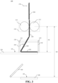
- FIG. 1 shows an apparatus 100 for making an electrode assembly according to an embodiment of the present application.
- the apparatus 100 includes a driving portion 110 and a first support portion 120.
- the driving portion 110 is used for driving pole pieces 200 to fall the pole pieces 200 from the driving portion 110.
- the first support portion 120 is arranged below the driving portion 110 and used for receiving the pole pieces 200 falling from the driving portion 110, so that the pole pieces 200 are stacked on the first support portion 120.
- the distance H1 between an initial position of an upper surface 121 of the first support portion 120 and the driving portion 110 is a preset value.
- the initial position of the upper surface 121 of the first support portion 120 is the position of the upper surface when the first support portion 120 receives the first pole piece of an electrode assembly.
- the preset value is in a range of W to 2W, that is, the preset value is greater than W and less than 2W, and W is the length of each pole piece of the electrode assembly.
- W is not limited in the embodiment of the present application, for example, W may be 100 mm to 200 mm, e.g., 101 mm, 111.1 mm, or 190 mm.
- an apparatus 100 for manufacturing an electrode assembly includes a driving portion 110 and a first support portion 120, the driving portion 110 being used for driving multiple pole pieces 200 to fall multiple pole pieces 200 from the driving portion 110; and the first support portion 120 being used for receiving the multiple pole pieces 200 falling from the driving portion 110, so that the pole pieces 200 are stacked on the first support portion 120, and an electrode assembly formed by stacking the multiple continuous pole pieces 200 is obtained. Since the distance H1 between the initial position of the upper surface 121 of the first support portion 120 and the driving portion 110 is in a range of W to 2W, the height space between the upper surface 121 of the first support portion 120 and the driving portion 110 can accommodate up to two pole pieces 200 to be stacked.
- the falling previous pole piece may be subjected to a downward force from the latter pole piece, and be stacked on the first support portion 120 under the action of the force.
- the pole pieces 200 are effectively stacked without performing complex operations using other components, and the stacking efficiency is high.
- the driving portion 110 includes a driving roller 111 and a driven roller 112 arranged opposite each other to allow the pole pieces 200 to fall between the driving roller 111 and the driven roller 112.
- the distance H1 between the initial position of the upper surface 121 of the first support portion 120 and the driving portion 110 is the distance H1 between the initial position and the center of the driving roller 111. That is, when the pole pieces 200 are driven to fall by the driving roller 111 and the driven roller 112, the distance H1 between the initial position of the upper surface 121 of the first support portion 120 and the center of the driving roller 111 is a preset value being in a range of W to 2W.
- the apparatus 100 will be described in detail below by taking the driving portion 110 including the driving roller 111 and the driven roller 112, and the distance H1 between the initial position of the upper surface 121 of the first support portion 120 and the center of the driving roller 111 being the preset value as an example.
- the preset value is in a range of W to 1 + 3 / 2 W to ensure that the latter pole piece 202 has a sufficient inclination relative to the upper surface 121 of the first support portion 120, so that the previous pole piece 202 is easier to stack when subjected to a downward force from the latter pole piece 203.
- the preset value is 1.5W.
- FIG. 2 shows a possible structure of pole pieces 200 of an embodiment of the present application.
- the pole pieces 200 include positive pole pieces 210 and negative pole pieces 220, the negative pole pieces 220 being alternately arranged on both sides of the positive pole pieces 210.
- the positive pole pieces 210 in the three pole pieces 200 are in the same line, where the negative pole piece 220 in the left pole piece 200 is at the lower side of the positive pole piece 210, the negative pole piece 220 in the middle pole piece 200 is at the upper side of the positive pole piece 210, and the negative pole piece 220 in the right pole piece 200 is at the lower side of the positive pole piece 210.
- the pole pieces 200 further include first separators 230 and second separators 240 arranged on both sides of the positive pole pieces 210 respectively to separate the positive pole pieces 210 from the negative pole pieces 220.
- the positive pole pieces 210 of two adjacent pole pieces 200 of the electrode assembly are disconnected, or scores are formed between the positive pole pieces 210 of the two adjacent pole pieces 200.
- the positive pole pieces 210 of the three pole pieces 200 are in the same line, but the positive pole pieces 210 of the three pole pieces 200 are disconnected from each other. At this time, during stacking of the pole pieces 200, two adjacent pole pieces 200 are connected to each other under the traction of the first separators 230 and the second separators 240.
- the positive pole pieces 210 of two adjacent pole pieces 200 are connected to each other, but scores or creases are formed at the adjacent positions, so that during stacking of the pole pieces 200, the two adjacent pole pieces 200 are connected to each other under the traction of the first separators 230, the second separators 240, and the positive pole pieces 210.
- a pole piece 200 is a composite pole piece strip, which is formed by attaching first separators 230 and second separators 240 to both sides of positive pole pieces 210, then alternately attaching negative pole pieces 220 to the first separators 230 and the second separators 240 on both sides of the positive pole pieces 210, and forming the pole piece 200 by rolling and compositing.
- the thickness of the pole piece 200 is denoted as S
- the length of each pole piece is denoted as W.
- the ith pole piece can be smoothly stacked on the (i-1)th pole piece 201.
- i is greater than 1 and less than M, that is, i is in a range of 2 to M, M being a positive integer greater than 1.
- the apparatus 100 further includes a blowing portion 130, arranged between the driving portion 110 and the first support portion 120, and used for blowing air to the first pole piece after the first pole piece falls from the driving portion 110, so that the first pole piece is stacked on the upper surface 121 of the first support portion 120.
- a blowing portion 130 arranged between the driving portion 110 and the first support portion 120, and used for blowing air to the first pole piece after the first pole piece falls from the driving portion 110, so that the first pole piece is stacked on the upper surface 121 of the first support portion 120.
- the first pole piece is blown to tilt by the blowing portion 130, such that the first pole piece may be stacked flat on the upper surface 121 of the first support portion 120 when subjected to a downward force from a second pole piece.
- the first separator 230 or the second separator 240 is to be in contact with the upper surface 121 of the first support portion 120 during stacking of the pole pieces 200.
- the positive pole piece 210 of the first pole piece needs to be located below the negative pole piece 220.
- the blowing portion 130 includes a first blowing mechanism 131 and a second blowing mechanism 132 arranged on both sides of a falling pole piece 200 respectively.
- the first blowing mechanism 131 is used for blowing air to the first pole piece when the side of the first pole piece where the negative pole piece 220 is faces the second blowing mechanism 132; and the second blowing mechanism 132 is used for blowing air to the first pole piece when the side of the first pole piece where the negative pole piece 220 is faces the first blowing mechanism 131.
- the first blowing mechanism 131 blows air to the first pole piece, so that the negative pole piece 220 of the first pole piece faces upward after the first pole piece is stacked flat on the upper surface 121 of the first support portion 120; and in contrast, when the side of the first pole piece where the negative pole piece 220 is faces the first blowing mechanism 131, the second blowing mechanism 132 blows air to the first pole piece, so that the negative pole piece 220 of the first pole piece faces upward after the first pole piece is stacked flat on the upper surface 121 of the first support portion 120.
- the last pole piece cannot be subjected to a downward force from another pole piece, the last pole piece may not be stacked on the surface of the stacked pole pieces 200 as flat as the other pole pieces 200.
- the apparatus 100 further includes a flattening mechanism 160 used for patting the electrode assembly to flatten the surface of the electrode assembly after the last pole piece of the electrode assembly is stacked.
- the electrode assembly can be shaped after being tapped by the flattening mechanism 160, and the surface of the resulting electrode assembly is flatter.
- the thickness of the pole pieces 200 stacked on the first support portion 120 gradually increases. As the thickness of the pole pieces stacked on the first support portion 120 increases, the distance between the surface of the pole pieces 200 stacked on the first support portion 120 and the driving portion 110 gradually decreases. To ensure that subsequent pole pieces 200 are effectively stacked, the distance between the surface of the pole pieces stacked on the first support portion 120 and the driving portion 110 needs to be maintained in a range of the preset value. That is, during stacking of the pole pieces 200, the distance between the surface of the pole pieces stacked on the first support portion 120 and the driving portion 110 is to be W to 2W, or, further, W to 1 + 3 / 2 W . Preferably, during stacking of the pole pieces 200, the distance between the surface of the pole pieces stacked on the first support portion 120 and the driving portion 110 remains unchanged, for example, equal to the preset value, e.g., 1.5W.
- the first support portion 120 descends by a distance S to maintain the distance between the surface of the pole pieces 200 stacked on the first support portion 120 and the driving portion 110 at the preset value.
- the driving portion 110 drives a pole piece with a length W, that is, every time one pole piece is driven, one more pole piece is added to the pole pieces 200 stacked on the first support portion 120. Therefore, every time the driving portion 110 drives a pole piece with a length W, the first support portion 120 descends by a distance S, i.e., the thickness of one pole piece. This allows the distance between the surface of the pole pieces stacked on the first support portion 120 and the driving portion 110 to remain unchanged, thereby ensuring that each pole piece 200 is effectively stacked, and every pole piece 200 is stacked with the same effect.
- a distance S i.e., the thickness of one pole piece.
- the pole pieces 200 can be effectively stacked as long as the distance between the surface of the pole pieces stacked on the first support portion 120 and the driving portion 110 is within an appropriate range. Therefore, in the embodiment of the present application, every time the driving portion 110 drives a pole piece 200 of another length, e.g., a pole piece 200 with a length K1 ⁇ W, i.e., a K1 pole piece 200, the first support portion 120 descends by a predetermined distance, e.g., a distance K2 ⁇ S, i.e., the thickness of a K2 pole piece 200.
- a predetermined distance e.g., a distance K2 ⁇ S, i.e., the thickness of a K2 pole piece 200.
- K1 may be equal to K2, as long as it is ensured that the distance between the surface of the pole pieces 200 stacked on the first support portion 120 and the driving portion 110 is within an appropriate range, e.g., W to 2W, or W to 1 + 3 / 2 W when each pole piece 200 is stacked.
- the apparatus 100 further includes a second support portion 140.
- the second support portion 140 is arranged below the driving portion 110, and used for rising to a position where the height of the upper surface 141 of the second support portion 140 is the same as the current height of the upper surface 121 of the first support portion 120 after N pole pieces 200 of the electrode assembly are stacked on the first support portion 120, and receiving the N pole pieces 200 from the first support portion 120.
- N is less than M
- M is the total number of the pole pieces 200 included in the electrode assembly
- M and N are positive integers greater than 1.
- the distance between the initial position of the upper surface 141 of the second support portion 140 and the center of the driving roller 111 is H2, H2 is greater than H1, and the value of H2 is not limited in the present application.
- the second support portion 140 rises to a position where the height of the upper surface 141 of the second support portion 140 is the same as the current height of the upper surface 121 of the first support portion 120 after N pole pieces are stacked on the first support portion 120, the rising height of the second support portion 140 being, e.g., H2-H1+N ⁇ S.
- the second support portion 140 receives the N pole pieces 200 from the first support portion 120, so that the remaining M-N pole pieces 200 are stacked on the second support portion 140. In this way, after the M pole pieces 200 are stacked, the second support portion 140 may transfer the M pole pieces 200 to the next process, while the first support portion 120 may immediately return to the initial position thereof and start manufacturing the next electrode assembly, thereby improving the efficiency in manufacturing electrode assemblies.
- the first support portion 120 and the second support portion 140 may be, e.g., support plates or insertion plates.
- One of the first support portion 120 and the second support portion 140 may be provided with an avoidance groove, and the other may be provided with a protrusion, the position of the avoidance groove corresponding to that of the protrusion.
- the first support portion 120 is provided with an avoidance groove
- the second support portion 140 is provided with a protrusion corresponding to the avoidance groove, the avoidance groove being cooperative with the protrusion, the protrusion being capable of extending into or retracting out of the avoidance groove, and the protrusion being used for carrying the stacked pole pieces 200.
- the second support portion 140 rises to a position where the height of the upper surface 141 of the second support portion 140 is the same as the current height of the upper surface 121 of the first support portion 120 after N pole pieces 200 are stacked on the first support portion 120, so that the protrusion extends into the avoidance groove to receive the N pole pieces 200. Then, the first support portion 120 is retracted in a horizontal direction, i.e., the avoidance groove moves relative to the protrusion, and the first support portion 120 no longer supports the pole pieces 200.
- the distance between the surface of the pole pieces 200 stacked on the second support portion 140 and the driving portion 110 gradually decreases.
- the distance between the surface of the pole pieces 200 stacked on the second support portion 140 and the center of the driving roller 222 needs to be maintained in a range of the preset value. That is, during stacking of the remaining M-N pole pieces 200, the distance between the surface of the pole pieces stacked on the second support portion 140 and the driving portion 110 is to be W to 2W, or, further, W to 1 + 3 / 2 W .
- the distance between the surface of the pole pieces stacked on the second support portion 140 and the driving portion 110 remains unchanged, for example, equal to the preset value, e.g., 1.5W.
- the second support portion 140 descends by a distance S to maintain the distance between the surface of the pole pieces stacked on the second support portion 140 and the driving portion 110 at the preset value.
- the driving portion 110 drives a pole piece with a length W, that is, every time one pole piece is driven, one more pole piece is added to the pole pieces 200 stacked on the second support portion 140. Therefore, every time the driving portion 110 drives a pole piece with a length W, the second support portion 140 descends by a distance S, i.e. the thickness of one pole piece. This allows the distance between the surface of the pole pieces stacked on the second support portion 140 and the driving portion 110 to remain unchanged, thereby ensuring that each subsequent pole piece 200 is effectively stacked, and every pole piece 200 is stacked with the same effect.
- the apparatus 100 further includes a cutting knife 170, arranged above the driving portion 110, and used for cutting off the pole piece 200 when the length of the pole piece 200 driven by the driving portion 110 reaches M ⁇ W, thereby completing stacking of M pole pieces 200 of an electrode assembly.
- a cutting knife 170 arranged above the driving portion 110, and used for cutting off the pole piece 200 when the length of the pole piece 200 driven by the driving portion 110 reaches M ⁇ W, thereby completing stacking of M pole pieces 200 of an electrode assembly.
- the apparatus 100 further includes an accommodating portion 150 arranged between the driving portion 110 and the first support portion 120.
- the accommodating portion 150 is used for accommodating pole pieces 200 to be stacked, and for example, as shown in FIG. 5 , the accommodating portion 150 includes a first baffle 151 and a second baffle 152 that are spaced apart and form a cavity for accommodating the pole pieces 200.
- the first baffle 151 and the second baffle 152 of the accommodating portion 150 may form a cavity for accommodating the pole pieces 200, so that the pole pieces 200 are stacked within the cavity, and the problems such as position offset caused during stacking of the pole pieces 200 are avoided.
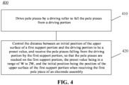
- the apparatus 100 for manufacturing an electrode assembly of the embodiments of the present application is described above in conjunction with FIGs. 1 to 3 , and a method 400 for manufacturing an electrode assembly provided in the embodiments of the present application will be described below in conjunction with FIGs. 4 to 6 .
- a method for manufacturing an electrode assembly is provided, applied to the apparatus 100 for manufacturing an electrode assembly, the apparatus 100 including a driving portion 110 and a first support portion 120, and the first support portion 120 being arranged below the driving portion 110.
- the method 400 includes some or all of the following steps.
- step 410 a pole piece 200 is driven by a driving portion 110 to fall the pole piece 200 from the driving portion 110.
- the distance H1 between an initial position of the upper surface 121 of the first support portion 120 and the driving portion 110 is controlled to be a preset value, and the pole pieces 200 falling from the driving portion 110 are received by the first support portion 120, so that the pole pieces 200 are stacked on the first support portion 120.
- the preset value is in a range of W to 2W
- the initial position is the position of the upper surface 121 of the first support portion 120 when receiving the first pole piece of the electrode assembly
- W is the length of each pole piece 200 of the electrode assembly.
- the driving portion 110 is controlled to drive the pole pieces 200 to fall the pole pieces 200 from the driving portion 110, the pole pieces 200 falling from the driving portion 110 are received by the first support portion 120, so that the pole pieces 200 are stacked on the first support portion 120, and an electrode assembly formed by stacking multiple continuous pole pieces 200 is obtained. Since the distance H1 between the initial position of the upper surface 121 of the first support portion 120 and the driving portion 110 is in a range of W to 2W, the space between the upper surface 121 of the first support portion 120 and the driving portion 120 can accommodate up to two pole pieces 200 to be stacked. In this way, when the driving portion 120 is driving the latter pole piece to fall, the falling previous pole piece 202 may be subjected to a downward force from the latter pole piece, and be stacked on the first support portion 120 under the action of the force.
- the preset value is in a range of W to 1 + 3 / 2 W to ensure that the latter pole piece 202 has a sufficient inclination relative to the upper surface 121 of the first support portion 120, so that the previous pole piece 202 is easier to stack when subjected to a downward force from the latter pole piece 203.
- the preset value is 1.5W.
- the driving portion 110 includes a driving roller 111 and a driven roller 112 arranged opposite each other to allow the pole pieces 200 to fall between the driving roller 111 and the driven roller 112.
- the distance H1 between the initial position of the upper surface 121 of the first support portion 120 and the driving portion 110 is the distance H1 between the initial position and the center of the driving roller 111.
- the distance between the surface of the pole pieces 200 stacked on the first support portion 120 and the driving portion 110 gradually decreases.
- the distance between the surface of the pole pieces 200 stacked on the first support portion 120 and the driving portion 110 needs to be maintained in a range of the preset value. Therefore, every time the driving portion 110 drives a pole piece with a length W, that is, every time one more pole piece is added to the pole pieces 200 stacked on the first support portion 120, the first support portion 120 descends by a distance S, i.e., the thickness of one pole piece. This allows the distance between the surface of the pole pieces stacked on the first support portion 120 and the driving portion 110 to remain unchanged, thereby ensuring that each pole piece 200 is effectively stacked, and every pole piece 200 is stacked with the same effect.
- the apparatus 100 further includes a second support portion 140 arranged below the driving portion 110.
- the method 400 further includes: the second support portion 140 is controlled to rise to a position where the height of the upper surface 141 of the second support portion 140 is the same as that of the upper surface 121 of the first support portion 120 after N pole pieces 200 of an electrode assembly are stacked on the first support portion 120, and the N pole pieces 200 are received from the first support portion 120 by the second support portion 140, N being less than M, M being the total number of the pole pieces 200 included in the electrode assembly, and M and N being positive integers greater than 1.
- the second support portion 140 is controlled to rise to a position where the height of the upper surface 141 of the second support portion 140 is the same as the current height of the upper surface 121 of the first support portion 120 after N pole pieces are stacked on the first support portion 120, and the second support portion 140 receives the N pole pieces 200 from the first support portion 120, so that the remaining M-N pole pieces 200 are stacked on the second support portion 140.
- the second support portion 140 may transfer the M pole pieces 200 to the next process, while the first support portion 120 may immediately return to the initial position thereof and start manufacturing the next electrode assembly, thereby improving the efficiency in manufacturing electrode assemblies.
- the method 400 further includes: every time the driving portion 110 drives the pole piece 200 with a length W, the second support portion 140 is controlled to descend by a distance S to maintain the distance between the surface of the pole pieces 200 stacked on the second support portion 140 and the driving portion 110 at the preset value.
- the distance between the surface of the pole pieces 200 stacked on the second support portion 140 and the driving portion 110 gradually decreases.
- the distance between the surface of the pole pieces 200 stacked on the second support portion 140 and the center of the driving roller 222 needs to be maintained in a range of the preset value. Therefore, in this embodiment, every time the driving portion 110 is controlled to drive a pole piece with a length W, that is, every time one more pole piece is added to the pole pieces 200 stacked on the second support portion 140, the second support portion 140 is controlled to descend by a distance S, i.e., the thickness of one pole piece. This allows the distance between the surface of the pole pieces 200 stacked on the second support portion 140 and the driving portion 110 to remain unchanged, thereby ensuring that each pole piece is effectively stacked, and every pole piece is stacked with the same effect.
- the apparatus 100 further includes a cutting knife 150 arranged above the driving portion 110; and the method 400 further includes: the pole pieces 200 are cut off by the cutting knife 150 when the length of the pole pieces 200 driven by the driving portion 110 reaches M ⁇ W.
- the apparatus 100 further includes an accommodating portion 150, arranged between the driving portion 110 and the first support portion 120, and including a first baffle 151 and a second baffle 152 that are spaced apart and form a cavity for accommodating the pole pieces 200.
- an accommodating portion 150 arranged between the driving portion 110 and the first support portion 120, and including a first baffle 151 and a second baffle 152 that are spaced apart and form a cavity for accommodating the pole pieces 200.
- the pole pieces 200 include positive pole pieces 210 and negative pole pieces 220, and the negative pole pieces 220 are alternately arranged on both sides of the positive pole pieces 210.
- the pole pieces 200 further include first separators 230 and second separators 240 arranged on both sides of the positive pole pieces 210 respectively to separate the positive pole pieces 210 from the negative pole pieces 220.
- the positive pole pieces 210 of two adjacent pole pieces 200 of the electrode assembly are disconnected, or scores are formed between the positive pole pieces 210 of the two adjacent pole pieces 200.
- the first separators 230 and the second separators 240 of two adjacent pole pieces 200 are continuous, and by disconnecting the positive pole pieces 210 of two adjacent pole pieces 200, the two adjacent pole pieces 200 may be conveniently stacked under the traction of the first separators 230 and the second separators 240; or, by forming scores or creases between the positive pole pieces 210 of two adjacent pole pieces 200, the two adjacent pole pieces 200 may be conveniently stacked under the traction of the first separators 230, the second separators 240, and the positive pole pieces 210.
- the apparatus 100 further includes a blowing portion 130 arranged between the driving portion 110 and the first support portion 120.
- the method 400 further includes: the blowing portion 130 blows air to the first pole piece after the first pole piece falls from the driving portion 110, so that the first pole piece is stacked on the upper surface 121 of the first support portion 120.
- the first pole piece Since there is no other pole piece providing a horizontal traction force for the first pole piece after the first pole piece falls, the first pole piece is blown to tilt by the blowing portion 130, such that the first pole piece may be stacked flat on the upper surface 121 of the first support portion 120 when subjected to a downward force from a second pole piece.
- the blowing portion 130 includes a first blowing mechanism 131 and a second blowing mechanism 132 arranged on both sides of a falling pole piece 200 respectively.
- the blowing air to the first pole piece by blowing portion 130 includes: the first blowing mechanism 131 blows air to the first pole piece when the side of the first pole piece where the negative pole piece 220 is faces the second blowing mechanism 132; and the second blowing mechanism 132 blows air to the first pole piece when the side of the first pole piece where the negative pole piece 220 is faces the first blowing mechanism 131.
- first separator 230 or a second separator 240 is to be in contact with the upper surface 121 of the first support portion 120 during stacking of the pole pieces 200. Since both sides of the positive pole piece 210 are coated with the first separator 230 and the second separator 240 respectively, the positive pole piece 210 of the first pole piece needs to be located below the negative pole piece 220.
- the first blowing mechanism 131 blows air to the first pole piece, so that the negative pole piece 220 of the first pole piece faces upward after the first pole piece is stacked flat on the upper surface 121 of the first support portion 120; and in contrast, when the side of the first pole piece where the negative pole piece 220 is faces the first blowing mechanism 131, the second blowing mechanism 132 blows air to the first pole piece, so that the negative pole piece 220 of the first pole piece faces upward after the first pole piece is stacked flat on the upper surface 121 of the first support portion 120.
- the apparatus 100 further includes a flattening mechanism 160; and the method 400 further includes: the electrode assembly is patted by the flattening mechanism 160 to flatten the surface of the electrode assembly after the last pole piece of the electrode assembly is stacked.
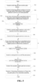
- FIG. 5 shows a potential specific implementation based on the method 400 as shown in FIG. 4 .
- an electrode assembly may be manufactured using the apparatus 100 as shown in FIG. 3 controlled by the method 400 according to the following steps.
- step 501 the driving portion 110 is controlled to drive the pole pieces 200.
- step 502 the blowing portion 130 is controlled to blow air to the first pole piece, and the first support portion 120 is controlled to arrive at an initial position.
- step 503 every time the driving roller 111 is controlled to drive a pole piece with a length W, the first support portion 120 is controlled to descend by a distance S.
- step 504 whether the number of the pole pieces 200 stacked on the first support portion 120 is N is judged.
- step 505 is performed.
- step 505 the second support portion 140 rises to a position where the first support portion 120 is.
- the second support portion 140 rises, so that the height of the surface 141 of the second support portion 140 is the same as the current height of the surface 121 of the first support portion 120.
- step 506 the first support portion 120 is controlled to move out, and the N pole pieces 200 are received by the second support portion 140.
- step 507 every time the driving roller 111 is controlled to drive a pole piece with a length W, the second support portion 140 is controlled to descend by a distance S.
- step 508 whether the length of the pole pieces 200 driven by the driving portion 110 reaches W ⁇ M is judged.
- step 509 is performed.
- step 509 the cutting knife 150 is controlled to cut off the pole pieces 200.
- step 510 whether the tail part of the pole pieces 200 is completely detached from the driving roller 111 is judged.
- step 511 is performed.
- step 511 the second support portion 140 is controlled to move out.
- step 512 the flattening mechanism 140 is controlled to flatten the last pole piece of the electrode assembly.
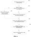
- FIG. 6 Reference may be made to FIG. 6 for specific control of the blowing part 130 and the first support portion 120 in step 502.
- step 601 it is determined that the first pole piece arrives at the blowing portion 130.
- step 602 whether the negative pole piece 220 of the first pole piece is on the right side is judged.
- step 603 If the negative pole piece 220 of the first pole piece is on the right side, step 603 is performed; and if the negative pole piece 220 of the first pole piece is on the left side, step 604 is performed.
- step 603 the first blowing mechanism 131 on the left side blows air to the first pole piece.
- step 604 the second blowing mechanism 132 on the right side blows air to the first pole piece.
- step 605 the first support portion 120 is controlled to move to the initial position thereof.
- the initial position of the first support portion 120 meets the condition that the distance H1 between the upper surface 121 of the first support portion 120 and the center of the driving roller 11 is a preset value, e.g., the preset value may be 1.5W.
- step 606 whether the tail part of the first pole piece arrives at the blowing portion 130 is determined.
- step 607 is performed.
- step 607 the blowing portion 130 is controlled to stop blowing.
- the distance H1 between the initial position of the upper surface 121 of the first support portion 120 and the driving roller 111 is set to be a preset value, so that the space between the upper surface 121 of the first support portion 120 and the driving portion 110 can accommodate up to two pole pieces 200 to be stacked.
- the driving portion 110 is driving the latter pole piece to fall
- the adjacent falling previous pole piece may be subjected to a downward force from the latter pole piece, and be stacked on the first support portion 120 under the action of the force.
- the pole pieces 200 are effectively stacked without performing complex operations using other components, and the stacking efficiency is high.
- the disclosed systems, apparatuses, and methods may be implemented in other manners.
- the apparatus example described above is only illustrative.
- the division of the units is only a logical function division. In an actual implementation, there may be other division methods.
- a plurality of units or components may be combined or may be integrated into another system, or some features may be ignored, or not implemented.
- the shown or discussed mutual coupling or direct coupling or communication connection may be indirect coupling or communication connection through some interfaces, apparatuses, or units, and may be in electrical, mechanical, or in other forms.
- the units described as separate components may or may not be physically separated, and components displayed as units may or may not be physical units, that is, may be located in one place, or may be distributed to a plurality of network units. Some or all of the units may be selected according to actual needs to achieve the purpose of the solution in this example.
Landscapes
- Engineering & Computer Science (AREA)
- Chemical & Material Sciences (AREA)
- Manufacturing & Machinery (AREA)
- Chemical Kinetics & Catalysis (AREA)
- Electrochemistry (AREA)
- General Chemical & Material Sciences (AREA)
- Mechanical Engineering (AREA)
- Materials Engineering (AREA)
- Secondary Cells (AREA)
Abstract
Description
- The present application relates to the technical field of batteries, in particular to an apparatus and method for manufacturing an electrode assembly.
- Energy conservation and emission reduction are the key to sustainable development of the automotive industry, and due to the advantages in energy conservation and environmental protection, electric vehicles have become an important part of sustainable development of the automotive industry. Battery technologies are an important factor affecting the development of electric vehicles.
- Generally, a battery includes a battery cell which includes an electrode assembly. The electrode assembly is formed by stacking or winding pole pieces including positive pole pieces and negative pole pieces, and electrical energy is generated by metal ions moving between the positive pole pieces and the negative pole pieces. In the manufacturing process of electrode assemblies formed by stacking pole pieces, an important process is to stack the pole pieces. Therefore, how to effectively stack pole pieces to obtain an electrode assembly has become a problem to be solved.
- The present application provides an apparatus and method for manufacturing an electrode assembly, which can be used for effectively stacking pole pieces to obtain an electrode assembly.
- In a first aspect, an apparatus for manufacturing an electrode assembly is provided, and the apparatus includes a driving portion used for driving pole pieces to fall the pole pieces from the driving portion; and a first support portion arranged below the driving portion and used for receiving the pole pieces falling from the driving portion, so that the pole pieces are stacked on the first support portion, where the distance between an initial position of the upper surface of the first support portion and the driving portion is a preset value, the preset value being in a range of W to 2W, the initial position being the position of the upper surface of the first support portion when receiving the first pole piece of the electrode assembly, and W being the length of each pole piece of the electrode assembly.
- In an embodiment of the present application, an apparatus for manufacturing an electrode assembly includes a driving portion and a first support portion, the driving portion being used for driving pole pieces to fall the pole pieces from the driving portion; and the first support portion being used for receiving the pole pieces falling from the driving portion, so that the pole pieces are stacked on the first support portion, and an electrode assembly formed by stacking multiple continuous pole pieces is obtained. Since the distance between the initial position of the upper surface of the first support portion and the driving portion is in a range of W to 2W, and W is the length of each pole piece, the space between the upper surface of the first support portion and the driving portion can accommodate up to two pole pieces to be stacked. In this way, when the driving portion is driving the latter pole piece to fall, the falling previous pole piece may be subjected to a downward force from the latter pole piece, and be stacked on the first support portion under the action of the force.
- In one implementation, the preset value is in a range of W to

- In one implementation, the driving portion includes a driving roller and a driven roller arranged opposite to allow the pole pieces to fall between the driving roller and the driven roller, and the distance between the initial position and the driving portion is the distance between the initial position and the center of the driving roller.
- In one implementation, every time the driving portion drives the pole piece with a length W, the first support portion descends by a distance S to maintain the distance between the surface of the pole pieces stacked on the first support portion and the driving portion at the preset value, S being the thickness of each pole piece.
- As the thickness of the pole pieces stacked on the first support portion increases, the distance between the surface of the pole pieces stacked on the first support portion and the driving portion gradually decreases. To ensure that subsequent pole pieces are effectively stacked, the distance between the surface of the pole pieces stacked on the first support portion and the driving portion needs to be maintained in a range of the preset value. Therefore, in this embodiment, every time the driving portion drives a pole piece with a length W, that is, every time one more pole piece is added to the pole pieces stacked on the first support portion, the first support portion descends by a distance S, i.e., the thickness of one pole piece. This allows the distance between the surface of the pole pieces stacked on the first support portion and the driving portion to remain unchanged, thereby ensuring that each pole piece is effectively stacked, and every pole piece is stacked with the same effect.
- In one implementation, the apparatus further includes a second support portion, arranged below the driving portion, and used for rising to a position where the height of the upper surface of the second support portion is the same as that of the upper surface of the first support portion after N pole pieces of the electrode assembly are stacked on the first support portion, and receiving the N pole pieces from the first support portion, N being less than M, M being the total number of the pole pieces included in the electrode assembly, and M and N being positive integers greater than 1.
- When multiple electrode assemblies are continuously manufactured, to improve the manufacturing efficiency, a second support portion may be arranged, used for rising to a position where the upper surface of the second support portion is at the same height as that of the first support portion after N pole pieces of an electrode assembly are stacked on the first support portion, and receiving the N pole pieces from the first support portion, so that the remaining M-N pole pieces are stacked on the second support portion. In this way, after the M pole pieces are stacked, the first support portion may immediately return to the initial position thereof and start manufacturing the next electrode assembly, thereby improving the efficiency in manufacturing electrode assemblies.
- In one implementation, every time the driving portion drives the pole piece with a length W, the second support portion descends by a distance S to maintain the distance between the surface of the pole pieces stacked on the second support portion and the driving portion at the preset value.
- Similarly, as the thickness of the pole pieces stacked on the second support portion increases, the distance between the surface of the pole pieces stacked on the second support portion and the driving portion gradually decreases. To ensure that subsequent pole pieces are effectively stacked, the distance between the surface of the pole pieces stacked on the second support portion and the driving portion needs to be maintained in a range of the preset value. Therefore, in this embodiment, every time the driving portion drives a pole piece with a length W, that is, every time one more pole piece is added to the pole pieces stacked on the second support portion, the second support portion descends by a distance S, i.e., the thickness of one pole piece. This allows the distance between the surface of the pole pieces stacked on the second support portion and the driving portion to remain unchanged, thereby ensuring that each pole piece is effectively stacked, and every pole piece is stacked with the same effect.
- In one implementation, the apparatus further includes a cutting knife arranged above the driving portion, and used for cutting off the pole pieces when the length of the pole pieces driven by the driving portion reaches M×W.
- In one implementation, the apparatus further includes an accommodating portion, arranged between the driving portion and the first support portion, and including a first baffle and a second baffle that are spaced apart and form a cavity for accommodating the pole pieces.
- In this embodiment, the first baffle and the second baffle of the accommodating portion may form a cavity for accommodating the pole pieces, so that the pole pieces are stacked within the cavity, and the problems such as position offset caused during stacking of the pole pieces are avoided.
- In one implementation, the pole pieces include positive pole pieces and negative pole pieces, the negative pole pieces being alternately arranged on both sides of the positive pole pieces.
- In one implementation, the pole pieces further include first separators and second separators arranged on both sides of the positive pole pieces respectively to separate the positive pole pieces from the negative pole pieces.
- In one implementation, the positive pole pieces of two adjacent pole pieces of the electrode assembly are disconnected, or scores are formed between the positive pole pieces of the two adjacent pole pieces.
- In this embodiment, the separators of two adjacent pole pieces are continuous, and by disconnecting the positive pole pieces of two adjacent pole pieces, the two adjacent pole pieces may be conveniently stacked under the traction of the separators; or, by forming scores or creases between the positive pole pieces of two adjacent pole pieces, the two adjacent pole pieces may be conveniently stacked under the traction of the separators and the positive pole pieces.
- In one implementation, the apparatus further includes a blowing portion, arranged between the driving portion and the first support portion, and used for blowing air to the first pole piece after the first pole piece falls from the driving portion, so that the first pole piece is stacked on the upper surface of the first support portion.
- Since there is no other pole piece providing a horizontal traction force for the first pole piece after the first pole piece falls, the first pole piece is blown to tilt by the blowing portion, such that the first pole piece may be stacked flat on the upper surface of the first support portion when subjected to a downward force from a second pole piece.
- In one implementation, the blowing portion includes a first blowing mechanism and a second blowing mechanism arranged on both sides of a falling pole piece respectively; the first blowing mechanism is used for blowing air to the first pole piece when the side of the first pole piece where the negative pole piece is faces the second blowing mechanism; and the second blowing mechanism is used for blowing air to the first pole piece when the side of the first pole piece where the negative pole piece is faces the first blowing mechanism.
- To locate a separator at the outermost side of the electrode assembly, a separator is to be in contact with the upper surface of the first support portion during stacking of the pole pieces. Since both sides of a positive pole piece are coated with the separators respectively, the positive pole piece of the first pole piece needs to be located below the negative pole piece. Therefore, in this embodiment, when the side of the first pole piece where the negative pole piece is faces the second blowing mechanism, the first blowing mechanism blows air to the first pole piece, so that the negative pole piece of the first pole piece faces upward after the first pole piece is stacked flat on the upper surface of the first support portion; and in contrast, when the side of the first pole piece where the negative pole piece is faces the first blowing mechanism, the second blowing mechanism blows air to the first pole piece, so that the negative pole piece of the first pole piece faces upward after the first pole piece is stacked flat on the upper surface of the first support portion.
- In one implementation, the apparatus further includes a flattening mechanism used for patting the electrode assembly to flatten the surface of the electrode assembly after the last pole piece of the electrode assembly is stacked.
- Since the last pole piece cannot be subjected to a downward force from another pole piece, the last pole piece may not be stacked on the surface of the stacked pole pieces as flat as the other pole pieces. After the last pole piece is stacked, the electrode assembly can be shaped after being tapped by the flattening mechanism, and the surface of the resulting electrode assembly is flatter.
- In a second aspect, a method for manufacturing an electrode assembly is provided, applied to an apparatus for manufacturing an electrode assembly; the apparatus includes a driving portion and a first support portion arranged below the driving portion; and the method includes: driving pole pieces by a driving roller to fall the pole pieces from the driving portion, controlling the distance between an initial position of the upper surface of the first support portion and the driving portion to be a preset value, and receiving the pole pieces falling from the driving portion by the first support portion, so that the pole pieces are stacked on the first support portion, the preset value being in a range of W to 2W, the initial position being the position of the upper surface of the first support portion when receiving the first pole piece of the electrode assembly, and W being the length of each pole piece of the electrode assembly.
- In one implementation, the preset value is in a range of W to

- In one implementation, the preset value is 1.5W.
- In one implementation, the driving portion includes a driving roller and a driven roller arranged opposite to allow the pole pieces to fall between the driving roller and the driven roller, and the distance between the initial position and the driving portion is the distance between the initial position and the center of the driving roller.
- In one implementation, the method further includes: every time the driving portion drives the pole piece with a length W, controlling the first support portion to descend by a distance S to maintain the distance between the surface of the pole pieces stacked on the first support portion and the driving portion at the preset value, S being the thickness of each pole piece.
- In one implementation, the apparatus further includes a second support portion arranged below the driving portion; and the method further includes: controlling the second support portion to rise to a position where the height of the upper surface of the second support portion is the same as that of the upper surface of the first support portion after N pole pieces of the electrode assembly are stacked on the first support portion, and receiving the N pole pieces from the first support portion by the second support portion, N being less than M, M being the total number of the pole pieces included in the electrode assembly, and M and N being positive integers greater than 1.
- In one implementation, the method further includes: every time the driving portion drives the pole piece with a length W, controlling the second support portion to descend by a distance S to maintain the distance between the surface of the pole pieces stacked on the second support portion and the driving portion at the preset value.
- In one implementation, the apparatus further includes a cutting knife arranged above the driving portion; and the method further includes: cutting off the pole pieces by the cutting knife when the length of the pole pieces driven by the driving portion reaches M×W.
- In one implementation, the apparatus further includes an accommodating portion, arranged between the driving portion and the first support portion, and including a first baffle and a second baffle that are spaced apart and form a cavity for accommodating the pole pieces.
- In one implementation, the pole pieces include positive pole pieces and negative pole pieces, the negative pole pieces being alternately arranged on both sides of the positive pole pieces.
- In one implementation, the pole pieces further include first separators and second separators arranged on both sides of the positive pole pieces respectively to separate the positive pole pieces from the negative pole pieces.
- In one implementation, the positive pole pieces of two adjacent pole pieces of the electrode assembly are disconnected, or scores are formed between the positive pole pieces of the two adjacent pole pieces.
- In one implementation, the apparatus further includes a blowing portion arranged between the driving portion and the first support portion; and the method further includes: blowing air to the first pole piece after the first pole piece falls from the driving portion, so that the first pole piece is stacked on the upper surface of the first support portion.
- In one implementation, the blowing portion includes a first blowing mechanism and a second blowing mechanism arranged on both sides of a falling pole piece respectively; and the blowing air to the fist pole piece by the blowing portion incudes: blowing air to the first pole piece by the first blowing mechanism when the side of the first pole piece where the negative pole piece is faces the second blowing mechanism, and blowing air to the first pole piece by the second blowing mechanism when the side of the first pole piece where the negative pole piece is faces the first blowing mechanism.
- In one implementation, the apparatus further includes a flattening mechanism; and the method further includes: patting the electrode assembly by the flattening mechanism to flatten the surface of the electrode assembly after the last pole piece of the electrode assembly is stacked.
- In a third aspect, a computer-readable storage medium is provided for storing a computer program that causes a computer to perform the method in the second aspect or any implementation of the second aspect described above.
- In a fourth aspect, a computer program is provided, which, when running on a computer, causes the computer to perform the method in the second aspect or any implementation of the second aspect described above.
-
-
FIG. 1 is a structural diagram of an apparatus for manufacturing an electrode assembly according to an embodiment of the present application; -
FIG. 2 is a structural diagram of pole pieces according to an embodiment of the present application; -
FIG. 3 is a structural diagram of an apparatus for manufacturing an electrode assembly according to another embodiment of the present application; -
FIG. 4 is a schematic flowchart of a method for manufacturing an electrode assembly according to an embodiment of the present application; -
FIG. 5 is a schematic diagram of a specific implementation based on the method shown inFIG. 4 . -
FIG. 6 is a schematic diagram based on the specific implementation of the steps related to the blowing portion in the method shown inFIG. 5 . - The drawings are not drawn to the actual scale.
- To make the objectives, technical solution, and advantages of the embodiments of the present application clearer, the technical solution in the embodiments of the present application will be clearly described below in conjunction with the drawings in the embodiments of the present application. Obviously, the described embodiments are part, not all, of the embodiments of the present application. Based on the embodiments of the present application, all other embodiments obtained by those of ordinary skill in the art without creative efforts shall fall within the protection scope of the present application.
- Unless otherwise defined, all technical and scientific terms used herein have the same meanings as those commonly understood by those skilled in the technical field of the present application. The terms used in the specification of the present application are only for the purpose of describing specific embodiments, and are not intended to limit the present application. The terms "include/comprise" and "have", as well as any variations thereof in the specification, claims, and accompanying drawings of the present application, are intended to cover non exclusive inclusion. The terms "first", "second", and the like in the specification and claims of the present application or in the above drawings are used for distinguishing different objects, rather than describing specific sequences or primary and secondary relationships. "Being vertical" does not mean being strictly vertical, but within an allowable range of error. "Being parallel" does not mean being strictly parallel, but within an allowable range of error.
- The reference to "embodiments" in the present application means that specific features, structures, or characteristics described in combination with the embodiments may be included in at least one embodiment of the present application. The phrase appearing in various parts of the specification does not necessarily refer to the same embodiment, nor is it an independent or alternative embodiment mutually exclusive of other embodiments. It is understood explicitly and implicitly by those skilled in the art that the embodiments described in the present application can be combined with other embodiments.
- In the description of the present application, it should be noted that the terms "mounting", "connecting", "connection" and "attachment" should be understood in a broad sense, unless otherwise explicitly specified or defined. For example, it may be a fixed connection, a detachable connection, or an integrated connection; and it may be a direct connection or an indirect connection through an intermediate medium, or may be a communication between the interior of two elements. For those skilled in the art, the specific meaning of the above terms in the present application may be understood according to specific circumstances.
- In the present application, the term "and/or" is only an association relationship for describing associated objects, indicating that three relationships may exist. For example, A and/or B may represent three situations: A exists alone, both A and B exist, and B exists alone. In addition, the character "/" in the present application generally means that the associated objects before and after it are in an "or" relationship.
- In the embodiments of the present application, the same reference numerals represent the same components, and for simplicity, detailed descriptions of the same components are omitted in different embodiments. It should be understood that the thickness, length, width, and other dimensions of various components in the embodiments of the present application shown in the accompanying drawings, as well as the overall thickness, length, width, and other dimensions of an integrated apparatus, are for illustrative purposes only, and should not constitute any limitation to the present application.
- "Multiple" in the present application refers to two or more, similarly, "multiple groups" refers to two or more groups, and "multiple pieces" refers to two or more pieces.
- In the environment of automotive industry that uses traditional energy as the power supply, environmental pollution is becoming increasingly serious. Positive development of new energy vehicles can reduce environmental pollution. Battery technologies are an important factor affecting the development of new energy vehicles.
- The battery mentioned herein refers to a single physical module that includes one or more battery cells to provide higher voltage and capacity. For example, the battery mentioned herein may include a battery module or battery pack, and the like. A battery generally includes a box for encapsulating one or more battery cells. The box may prevent liquid or other foreign matters from affecting charging or discharging of the battery cells.
- In one implementation, battery cells may include lithium ion secondary batteries, lithium ion primary batteries, lithium sulfur batteries, sodium lithium ion batteries, sodium ion batteries, or magnesium ion batteries, which are not limited in the embodiments of the present application. Generally, a battery cell may also be called a cell. A battery cell may be cylindrical, flat, rectangular, or in other regular or irregular shapes. The technical solution of the embodiments of the present application may be applied to battery cells of any shape.
- A battery cell includes an electrode assembly and an electrolyte solution, the electrode assembly including positive pole pieces, negative pole pieces, and separators. A battery cell works by mainly relying on metal ions moving between the positive and negative pole pieces. A positive pole piece includes a positive current collector and a positive active material layer, the surface of the positive current collector being coated with the positive active material layer, the current collector not coated with the positive active material layer protruding from the current collector coated with the positive active material layer, and the current collector not coated with the positive active material layer being used as a positive tab. Taking a lithium-ion battery as an example, the material of the positive current collector may be aluminum, and the positive active material may be lithium cobalt oxide, lithium iron phosphate, ternary lithium, lithium manganate, or the like. A negative pole piece includes a negative current collector and a negative active material layer, the surface of the negative current collector being coated with the negative active material layer, the current collector not coated with the negative active material layer protruding from the current collector coated with the negative active material layer, and the current collector not coated with the negative active material layer being used as a negative tab. The material of the negative current collector may be copper, and the negative active material may be carbon, silicon, or the like. To prevent fusing when a large current passes, multiple positive tabs are stacked together, and also multiple negative tabs are stacked together. The material of a separator may be polypropylene (PP), polyethylene (PE), or the like.
- The electrode assembly of an embodiment of the present application includes multiple pole pieces stacked together, and the embodiment of the present application provides a solution to effectively stack the pole pieces to obtain the electrode assembly, that is, the distance between a first support portion and a driving portion is reasonably set to be W to 2W, W being the length of each pole piece, so that the pole pieces falling from the driving portion are effectively stacked on the first support portion under a downward force provided by the driving portion to the pole pieces.
-
FIG. 1 shows anapparatus 100 for making an electrode assembly according to an embodiment of the present application. As shown inFIG. 1 , theapparatus 100 includes a drivingportion 110 and afirst support portion 120. - The driving
portion 110 is used for drivingpole pieces 200 to fall thepole pieces 200 from the drivingportion 110. - The
first support portion 120 is arranged below the drivingportion 110 and used for receiving thepole pieces 200 falling from the drivingportion 110, so that thepole pieces 200 are stacked on thefirst support portion 120. The distance H1 between an initial position of anupper surface 121 of thefirst support portion 120 and the drivingportion 110 is a preset value. The initial position of theupper surface 121 of thefirst support portion 120 is the position of the upper surface when thefirst support portion 120 receives the first pole piece of an electrode assembly. In an embodiment of the present application, the preset value is in a range of W to 2W, that is, the preset value is greater than W and less than 2W, and W is the length of each pole piece of the electrode assembly. - The value of W is not limited in the embodiment of the present application, for example, W may be 100 mm to 200 mm, e.g., 101 mm, 111.1 mm, or 190 mm.
- It can be seen that in an embodiment of the present application, an
apparatus 100 for manufacturing an electrode assembly includes a drivingportion 110 and afirst support portion 120, the drivingportion 110 being used for drivingmultiple pole pieces 200 to fallmultiple pole pieces 200 from the drivingportion 110; and thefirst support portion 120 being used for receiving themultiple pole pieces 200 falling from the drivingportion 110, so that thepole pieces 200 are stacked on thefirst support portion 120, and an electrode assembly formed by stacking the multiplecontinuous pole pieces 200 is obtained. Since the distance H1 between the initial position of theupper surface 121 of thefirst support portion 120 and the drivingportion 110 is in a range of W to 2W, the height space between theupper surface 121 of thefirst support portion 120 and the drivingportion 110 can accommodate up to twopole pieces 200 to be stacked. In this way, when the drivingportion 110 is driving the latter pole piece to fall, the falling previous pole piece may be subjected to a downward force from the latter pole piece, and be stacked on thefirst support portion 120 under the action of the force. Moreover, thepole pieces 200 are effectively stacked without performing complex operations using other components, and the stacking efficiency is high. - In one implementation, the driving
portion 110 includes a drivingroller 111 and a drivenroller 112 arranged opposite each other to allow thepole pieces 200 to fall between the drivingroller 111 and the drivenroller 112. At this time, the distance H1 between the initial position of theupper surface 121 of thefirst support portion 120 and the drivingportion 110 is the distance H1 between the initial position and the center of the drivingroller 111. That is, when thepole pieces 200 are driven to fall by the drivingroller 111 and the drivenroller 112, the distance H1 between the initial position of theupper surface 121 of thefirst support portion 120 and the center of the drivingroller 111 is a preset value being in a range of W to 2W. Theapparatus 100 will be described in detail below by taking the drivingportion 110 including the drivingroller 111 and the drivenroller 112, and the distance H1 between the initial position of theupper surface 121 of thefirst support portion 120 and the center of the drivingroller 111 being the preset value as an example. - In one implementation, the preset value is in a range of W to

latter pole piece 202 has a sufficient inclination relative to theupper surface 121 of thefirst support portion 120, so that theprevious pole piece 202 is easier to stack when subjected to a downward force from thelatter pole piece 203. Preferably, the preset value is 1.5W. -
FIG. 2 shows a possible structure ofpole pieces 200 of an embodiment of the present application. As shown inFIG. 2 , thepole pieces 200 includepositive pole pieces 210 andnegative pole pieces 220, thenegative pole pieces 220 being alternately arranged on both sides of thepositive pole pieces 210. - For example, as shown in
FIG. 2 in which threepole pieces 200 are illustrated, thepositive pole pieces 210 in the threepole pieces 200 are in the same line, where thenegative pole piece 220 in theleft pole piece 200 is at the lower side of thepositive pole piece 210, thenegative pole piece 220 in themiddle pole piece 200 is at the upper side of thepositive pole piece 210, and thenegative pole piece 220 in theright pole piece 200 is at the lower side of thepositive pole piece 210. - As shown in
FIG. 2 , thepole pieces 200 further includefirst separators 230 andsecond separators 240 arranged on both sides of thepositive pole pieces 210 respectively to separate thepositive pole pieces 210 from thenegative pole pieces 220. - In one implementation, the
positive pole pieces 210 of twoadjacent pole pieces 200 of the electrode assembly are disconnected, or scores are formed between thepositive pole pieces 210 of the twoadjacent pole pieces 200. - For example, as shown in
FIG. 2 , thepositive pole pieces 210 of the threepole pieces 200 are in the same line, but thepositive pole pieces 210 of the threepole pieces 200 are disconnected from each other. At this time, during stacking of thepole pieces 200, twoadjacent pole pieces 200 are connected to each other under the traction of thefirst separators 230 and thesecond separators 240. - Alternatively, unlike
FIG. 2 , thepositive pole pieces 210 of twoadjacent pole pieces 200 are connected to each other, but scores or creases are formed at the adjacent positions, so that during stacking of thepole pieces 200, the twoadjacent pole pieces 200 are connected to each other under the traction of thefirst separators 230, thesecond separators 240, and thepositive pole pieces 210. - Specifically, as shown in
FIG. 2 , apole piece 200 is a composite pole piece strip, which is formed by attachingfirst separators 230 andsecond separators 240 to both sides ofpositive pole pieces 210, then alternately attachingnegative pole pieces 220 to thefirst separators 230 and thesecond separators 240 on both sides of thepositive pole pieces 210, and forming thepole piece 200 by rolling and compositing. Therefore, thepole piece 200 is formed by compositing two layers of separators, one layer ofpositive pole pieces 210, and one layer ofnegative pole pieces 220, and has a thickness of S=2Sa+Sb+Sc, where Sa is the thickness of theseparators 130 and is also the thickness of theseparators 140, Sb is the thickness of thepositive pole pieces 210, Sc is the thickness of thenegative pole pieces 220, and the length of thepole piece 220 along the strip direction is W. Hereinafter, the thickness of thepole piece 200 is denoted as S, and the length of each pole piece is denoted as W. - During stacking of the
pole piece 200, as shown inFIG. 1 , taking theith pole piece 202 as an example, after theith pole piece 202 falls between the drivingroller 111 and the drivenroller 112 and is to be stacked, on the one hand, because the drivingportion 110 drives the (i+1)th pole piece 203 subsequently, the (i+1)th pole piece 203 receives a downward driving force, and theith pole piece 202 may receive a downward force from the (i+1)th pole piece 203; and on the other hand, due to the traction of the (i-1)pole piece 201 stacked on thefirst support portion 120 to theith pole piece 202, theith pole piece 202 is subjected to left and downward traction forces. In this way, under the traction force of the (i-1)th pole piece 201 and the downward force provided by the (i+1)th pole piece 203, and combined with the gravity, the ith pole piece can be smoothly stacked on the (i-1)th pole piece 201. - It should be understood that here, i is greater than 1 and less than M, that is, i is in a range of 2 to M, M being a positive integer greater than 1. When i=1, that is, for the first pole piece, due to lack of the aforementioned traction force, an additional horizontal force is required to stack the first pole piece flat on the
upper surface 121 of thefirst support portion 120. - In one implementation, as shown in
FIG. 3 , theapparatus 100 further includes a blowingportion 130, arranged between the drivingportion 110 and thefirst support portion 120, and used for blowing air to the first pole piece after the first pole piece falls from the drivingportion 110, so that the first pole piece is stacked on theupper surface 121 of thefirst support portion 120. - It may be seen that, since there is no other pole piece providing a horizontal traction force for the first pole piece after the first pole piece falls, the first pole piece is blown to tilt by the blowing
portion 130, such that the first pole piece may be stacked flat on theupper surface 121 of thefirst support portion 120 when subjected to a downward force from a second pole piece. - Generally, to locate a
first separator 230 or asecond separator 240 at the outermost side of the electrode assembly, thefirst separator 230 or thesecond separator 240 is to be in contact with theupper surface 121 of thefirst support portion 120 during stacking of thepole pieces 200. As can be seen fromFIG. 2 , since both sides of thepositive pole piece 210 are coated with thefirst separator 230 and thesecond separator 240 respectively, thepositive pole piece 210 of the first pole piece needs to be located below thenegative pole piece 220. - For example, as shown in
FIG. 3 , the blowingportion 130 includes afirst blowing mechanism 131 and asecond blowing mechanism 132 arranged on both sides of a fallingpole piece 200 respectively. Thefirst blowing mechanism 131 is used for blowing air to the first pole piece when the side of the first pole piece where thenegative pole piece 220 is faces thesecond blowing mechanism 132; and thesecond blowing mechanism 132 is used for blowing air to the first pole piece when the side of the first pole piece where thenegative pole piece 220 is faces thefirst blowing mechanism 131. - Therefore, when the side of the first pole piece where the
negative pole piece 220 is faces thesecond blowing mechanism 132, thefirst blowing mechanism 131 blows air to the first pole piece, so that thenegative pole piece 220 of the first pole piece faces upward after the first pole piece is stacked flat on theupper surface 121 of thefirst support portion 120; and in contrast, when the side of the first pole piece where thenegative pole piece 220 is faces thefirst blowing mechanism 131, thesecond blowing mechanism 132 blows air to the first pole piece, so that thenegative pole piece 220 of the first pole piece faces upward after the first pole piece is stacked flat on theupper surface 121 of thefirst support portion 120. - Since the last pole piece cannot be subjected to a downward force from another pole piece, the last pole piece may not be stacked on the surface of the stacked
pole pieces 200 as flat as theother pole pieces 200. - In one implementation, the
apparatus 100 further includes aflattening mechanism 160 used for patting the electrode assembly to flatten the surface of the electrode assembly after the last pole piece of the electrode assembly is stacked. - In this way, after the
last pole piece 200 is stacked, the electrode assembly can be shaped after being tapped by theflattening mechanism 160, and the surface of the resulting electrode assembly is flatter. - As can be seen from
FIGs. 1 and3 , during stacking of thepole pieces 200, the thickness of thepole pieces 200 stacked on thefirst support portion 120 gradually increases. As the thickness of the pole pieces stacked on thefirst support portion 120 increases, the distance between the surface of thepole pieces 200 stacked on thefirst support portion 120 and the drivingportion 110 gradually decreases. To ensure thatsubsequent pole pieces 200 are effectively stacked, the distance between the surface of the pole pieces stacked on thefirst support portion 120 and the drivingportion 110 needs to be maintained in a range of the preset value. That is, during stacking of thepole pieces 200, the distance between the surface of the pole pieces stacked on thefirst support portion 120 and the drivingportion 110 is to be W to 2W, or, further, W to
pole pieces 200, the distance between the surface of the pole pieces stacked on thefirst support portion 120 and the drivingportion 110 remains unchanged, for example, equal to the preset value, e.g., 1.5W. - In one implementation, every time the driving
portion 110 drives a pole piece with a length W, thefirst support portion 120 descends by a distance S to maintain the distance between the surface of thepole pieces 200 stacked on thefirst support portion 120 and the drivingportion 110 at the preset value. - Every time the driving
portion 110 drives a pole piece with a length W, that is, every time one pole piece is driven, one more pole piece is added to thepole pieces 200 stacked on thefirst support portion 120. Therefore, every time the drivingportion 110 drives a pole piece with a length W, thefirst support portion 120 descends by a distance S, i.e., the thickness of one pole piece. This allows the distance between the surface of the pole pieces stacked on thefirst support portion 120 and the drivingportion 110 to remain unchanged, thereby ensuring that eachpole piece 200 is effectively stacked, and everypole piece 200 is stacked with the same effect. - Actually, the
pole pieces 200 can be effectively stacked as long as the distance between the surface of the pole pieces stacked on thefirst support portion 120 and the drivingportion 110 is within an appropriate range. Therefore, in the embodiment of the present application, every time the drivingportion 110 drives apole piece 200 of another length, e.g., apole piece 200 with a length K1×W, i.e., aK1 pole piece 200, thefirst support portion 120 descends by a predetermined distance, e.g., a distance K2×S, i.e., the thickness of aK2 pole piece 200. K1 may be equal to K2, as long as it is ensured that the distance between the surface of thepole pieces 200 stacked on thefirst support portion 120 and the drivingportion 110 is within an appropriate range, e.g., W to 2W, or W to
pole piece 200 is stacked. - When multiple electrode assemblies are continuously manufactured, to improve the manufacturing efficiency, in one implementation, the
apparatus 100 further includes asecond support portion 140. Thesecond support portion 140 is arranged below the drivingportion 110, and used for rising to a position where the height of theupper surface 141 of thesecond support portion 140 is the same as the current height of theupper surface 121 of thefirst support portion 120 afterN pole pieces 200 of the electrode assembly are stacked on thefirst support portion 120, and receiving theN pole pieces 200 from thefirst support portion 120. N is less than M, M is the total number of thepole pieces 200 included in the electrode assembly, and M and N are positive integers greater than 1. - For example, as shown in
FIG. 3 , the distance between the initial position of theupper surface 141 of thesecond support portion 140 and the center of the drivingroller 111 is H2, H2 is greater than H1, and the value of H2 is not limited in the present application. Thesecond support portion 140 rises to a position where the height of theupper surface 141 of thesecond support portion 140 is the same as the current height of theupper surface 121 of thefirst support portion 120 after N pole pieces are stacked on thefirst support portion 120, the rising height of thesecond support portion 140 being, e.g., H2-H1+N×S. Next, thesecond support portion 140 receives theN pole pieces 200 from thefirst support portion 120, so that the remainingM-N pole pieces 200 are stacked on thesecond support portion 140. In this way, after theM pole pieces 200 are stacked, thesecond support portion 140 may transfer theM pole pieces 200 to the next process, while thefirst support portion 120 may immediately return to the initial position thereof and start manufacturing the next electrode assembly, thereby improving the efficiency in manufacturing electrode assemblies. - The
first support portion 120 and thesecond support portion 140 may be, e.g., support plates or insertion plates. One of thefirst support portion 120 and thesecond support portion 140 may be provided with an avoidance groove, and the other may be provided with a protrusion, the position of the avoidance groove corresponding to that of the protrusion. For example, thefirst support portion 120 is provided with an avoidance groove, and thesecond support portion 140 is provided with a protrusion corresponding to the avoidance groove, the avoidance groove being cooperative with the protrusion, the protrusion being capable of extending into or retracting out of the avoidance groove, and the protrusion being used for carrying the stackedpole pieces 200. Thesecond support portion 140 rises to a position where the height of theupper surface 141 of thesecond support portion 140 is the same as the current height of theupper surface 121 of thefirst support portion 120 afterN pole pieces 200 are stacked on thefirst support portion 120, so that the protrusion extends into the avoidance groove to receive theN pole pieces 200. Then, thefirst support portion 120 is retracted in a horizontal direction, i.e., the avoidance groove moves relative to the protrusion, and thefirst support portion 120 no longer supports thepole pieces 200. - Similarly, as the thickness of the
pole pieces 200 stacked on thesecond support portion 140 increases, the distance between the surface of thepole pieces 200 stacked on thesecond support portion 140 and the drivingportion 110 gradually decreases. To ensure thatsubsequent pole pieces 200 are effectively stacked, the distance between the surface of thepole pieces 200 stacked on thesecond support portion 140 and the center of the driving roller 222 needs to be maintained in a range of the preset value. That is, during stacking of the remainingM-N pole pieces 200, the distance between the surface of the pole pieces stacked on thesecond support portion 140 and the drivingportion 110 is to be W to 2W, or, further, W to
pole pieces 200, the distance between the surface of the pole pieces stacked on thesecond support portion 140 and the drivingportion 110 remains unchanged, for example, equal to the preset value, e.g., 1.5W. - In one implementation, every time the driving
portion 110 drives a pole piece with a length W, thesecond support portion 140 descends by a distance S to maintain the distance between the surface of the pole pieces stacked on thesecond support portion 140 and the drivingportion 110 at the preset value. - Every time the driving
portion 110 drives a pole piece with a length W, that is, every time one pole piece is driven, one more pole piece is added to thepole pieces 200 stacked on thesecond support portion 140. Therefore, every time the drivingportion 110 drives a pole piece with a length W, thesecond support portion 140 descends by a distance S, i.e. the thickness of one pole piece. This allows the distance between the surface of the pole pieces stacked on thesecond support portion 140 and the drivingportion 110 to remain unchanged, thereby ensuring that eachsubsequent pole piece 200 is effectively stacked, and everypole piece 200 is stacked with the same effect. - Reference may be made to the previous description of the
first support portion 120 for specific details of thesecond support portion 140, which will not be repeated here for simplicity. - In one implementation, as shown in
FIG. 3 , theapparatus 100 further includes a cuttingknife 170, arranged above the drivingportion 110, and used for cutting off thepole piece 200 when the length of thepole piece 200 driven by the drivingportion 110 reaches M×W, thereby completing stacking ofM pole pieces 200 of an electrode assembly. - In one implementation, the
apparatus 100 further includes anaccommodating portion 150 arranged between the drivingportion 110 and thefirst support portion 120. Theaccommodating portion 150 is used foraccommodating pole pieces 200 to be stacked, and for example, as shown inFIG. 5 , theaccommodating portion 150 includes afirst baffle 151 and asecond baffle 152 that are spaced apart and form a cavity for accommodating thepole pieces 200. - In this embodiment, the
first baffle 151 and thesecond baffle 152 of theaccommodating portion 150 may form a cavity for accommodating thepole pieces 200, so that thepole pieces 200 are stacked within the cavity, and the problems such as position offset caused during stacking of thepole pieces 200 are avoided. - The
apparatus 100 for manufacturing an electrode assembly of the embodiments of the present application is described above in conjunction withFIGs. 1 to 3 , and amethod 400 for manufacturing an electrode assembly provided in the embodiments of the present application will be described below in conjunction withFIGs. 4 to 6 . - As shown in
FIG. 4 , a method for manufacturing an electrode assembly is provided, applied to theapparatus 100 for manufacturing an electrode assembly, theapparatus 100 including a drivingportion 110 and afirst support portion 120, and thefirst support portion 120 being arranged below the drivingportion 110. As shown inFIG. 4 , themethod 400 includes some or all of the following steps. - In
step 410, apole piece 200 is driven by a drivingportion 110 to fall thepole piece 200 from the drivingportion 110. - In
step 420, the distance H1 between an initial position of theupper surface 121 of thefirst support portion 120 and the drivingportion 110 is controlled to be a preset value, and thepole pieces 200 falling from the drivingportion 110 are received by thefirst support portion 120, so that thepole pieces 200 are stacked on thefirst support portion 120. The preset value is in a range of W to 2W, the initial position is the position of theupper surface 121 of thefirst support portion 120 when receiving the first pole piece of the electrode assembly, and W is the length of eachpole piece 200 of the electrode assembly. - Based on the
method 400, the drivingportion 110 is controlled to drive thepole pieces 200 to fall thepole pieces 200 from the drivingportion 110, thepole pieces 200 falling from the drivingportion 110 are received by thefirst support portion 120, so that thepole pieces 200 are stacked on thefirst support portion 120, and an electrode assembly formed by stacking multiplecontinuous pole pieces 200 is obtained. Since the distance H1 between the initial position of theupper surface 121 of thefirst support portion 120 and the drivingportion 110 is in a range of W to 2W, the space between theupper surface 121 of thefirst support portion 120 and the drivingportion 120 can accommodate up to twopole pieces 200 to be stacked. In this way, when the drivingportion 120 is driving the latter pole piece to fall, the fallingprevious pole piece 202 may be subjected to a downward force from the latter pole piece, and be stacked on thefirst support portion 120 under the action of the force. - In one implementation, the preset value is in a range of W to

latter pole piece 202 has a sufficient inclination relative to theupper surface 121 of thefirst support portion 120, so that theprevious pole piece 202 is easier to stack when subjected to a downward force from thelatter pole piece 203. Preferably, the preset value is 1.5W. - In one implementation, the driving
portion 110 includes a drivingroller 111 and a drivenroller 112 arranged opposite each other to allow thepole pieces 200 to fall between the drivingroller 111 and the drivenroller 112. At this time, the distance H1 between the initial position of theupper surface 121 of thefirst support portion 120 and the drivingportion 110 is the distance H1 between the initial position and the center of the drivingroller 111. - As the thickness of the
pole pieces 200 stacked on thefirst support portion 120 increases, the distance between the surface of thepole pieces 200 stacked on thefirst support portion 120 and the drivingportion 110 gradually decreases. To ensure thatsubsequent pole pieces 200 are effectively stacked, the distance between the surface of thepole pieces 200 stacked on thefirst support portion 120 and the drivingportion 110 needs to be maintained in a range of the preset value. Therefore, every time the drivingportion 110 drives a pole piece with a length W, that is, every time one more pole piece is added to thepole pieces 200 stacked on thefirst support portion 120, thefirst support portion 120 descends by a distance S, i.e., the thickness of one pole piece. This allows the distance between the surface of the pole pieces stacked on thefirst support portion 120 and the drivingportion 110 to remain unchanged, thereby ensuring that eachpole piece 200 is effectively stacked, and everypole piece 200 is stacked with the same effect. - When multiple electrode assemblies are continuously manufactured, to improve the manufacturing efficiency, in one implementation, the
apparatus 100 further includes asecond support portion 140 arranged below the drivingportion 110. Themethod 400 further includes: thesecond support portion 140 is controlled to rise to a position where the height of theupper surface 141 of thesecond support portion 140 is the same as that of theupper surface 121 of thefirst support portion 120 afterN pole pieces 200 of an electrode assembly are stacked on thefirst support portion 120, and theN pole pieces 200 are received from thefirst support portion 120 by thesecond support portion 140, N being less than M, M being the total number of thepole pieces 200 included in the electrode assembly, and M and N being positive integers greater than 1. - The
second support portion 140 is controlled to rise to a position where the height of theupper surface 141 of thesecond support portion 140 is the same as the current height of theupper surface 121 of thefirst support portion 120 after N pole pieces are stacked on thefirst support portion 120, and thesecond support portion 140 receives theN pole pieces 200 from thefirst support portion 120, so that the remainingM-N pole pieces 200 are stacked on thesecond support portion 140. In this way, after theM pole pieces 200 are stacked, thesecond support portion 140 may transfer theM pole pieces 200 to the next process, while thefirst support portion 120 may immediately return to the initial position thereof and start manufacturing the next electrode assembly, thereby improving the efficiency in manufacturing electrode assemblies. - In one implementation, the
method 400 further includes: every time the drivingportion 110 drives thepole piece 200 with a length W, thesecond support portion 140 is controlled to descend by a distance S to maintain the distance between the surface of thepole pieces 200 stacked on thesecond support portion 140 and the drivingportion 110 at the preset value. - Similarly, as the thickness of the
pole pieces 200 stacked on thesecond support portion 140 increases, the distance between the surface of thepole pieces 200 stacked on thesecond support portion 140 and the drivingportion 110 gradually decreases. To ensure thatsubsequent pole pieces 200 are effectively stacked, the distance between the surface of thepole pieces 200 stacked on thesecond support portion 140 and the center of the driving roller 222 needs to be maintained in a range of the preset value. Therefore, in this embodiment, every time the drivingportion 110 is controlled to drive a pole piece with a length W, that is, every time one more pole piece is added to thepole pieces 200 stacked on thesecond support portion 140, thesecond support portion 140 is controlled to descend by a distance S, i.e., the thickness of one pole piece. This allows the distance between the surface of thepole pieces 200 stacked on thesecond support portion 140 and the drivingportion 110 to remain unchanged, thereby ensuring that each pole piece is effectively stacked, and every pole piece is stacked with the same effect. - In one implementation, the
apparatus 100 further includes a cuttingknife 150 arranged above the drivingportion 110; and themethod 400 further includes: thepole pieces 200 are cut off by the cuttingknife 150 when the length of thepole pieces 200 driven by the drivingportion 110 reaches M×W. - In one implementation, the
apparatus 100 further includes anaccommodating portion 150, arranged between the drivingportion 110 and thefirst support portion 120, and including afirst baffle 151 and asecond baffle 152 that are spaced apart and form a cavity for accommodating thepole pieces 200. Thus, thepole pieces 200 are stacked within the cavity, and the problems such as position offset caused during stacking of thepole pieces 200 are avoided. - In one implementation, the
pole pieces 200 includepositive pole pieces 210 andnegative pole pieces 220, and thenegative pole pieces 220 are alternately arranged on both sides of thepositive pole pieces 210. - In one implementation, the
pole pieces 200 further includefirst separators 230 andsecond separators 240 arranged on both sides of thepositive pole pieces 210 respectively to separate thepositive pole pieces 210 from thenegative pole pieces 220. - In one implementation, the
positive pole pieces 210 of twoadjacent pole pieces 200 of the electrode assembly are disconnected, or scores are formed between thepositive pole pieces 210 of the twoadjacent pole pieces 200. - The
first separators 230 and thesecond separators 240 of twoadjacent pole pieces 200 are continuous, and by disconnecting thepositive pole pieces 210 of twoadjacent pole pieces 200, the twoadjacent pole pieces 200 may be conveniently stacked under the traction of thefirst separators 230 and thesecond separators 240; or, by forming scores or creases between thepositive pole pieces 210 of twoadjacent pole pieces 200, the twoadjacent pole pieces 200 may be conveniently stacked under the traction of thefirst separators 230, thesecond separators 240, and thepositive pole pieces 210. - In one implementation, the
apparatus 100 further includes a blowingportion 130 arranged between the drivingportion 110 and thefirst support portion 120. Themethod 400 further includes: the blowingportion 130 blows air to the first pole piece after the first pole piece falls from the drivingportion 110, so that the first pole piece is stacked on theupper surface 121 of thefirst support portion 120. - Since there is no other pole piece providing a horizontal traction force for the first pole piece after the first pole piece falls, the first pole piece is blown to tilt by the blowing
portion 130, such that the first pole piece may be stacked flat on theupper surface 121 of thefirst support portion 120 when subjected to a downward force from a second pole piece. - In one implementation, the blowing
portion 130 includes afirst blowing mechanism 131 and asecond blowing mechanism 132 arranged on both sides of a fallingpole piece 200 respectively. The blowing air to the first pole piece by blowingportion 130 includes: thefirst blowing mechanism 131 blows air to the first pole piece when the side of the first pole piece where thenegative pole piece 220 is faces thesecond blowing mechanism 132; and thesecond blowing mechanism 132 blows air to the first pole piece when the side of the first pole piece where thenegative pole piece 220 is faces thefirst blowing mechanism 131. - To locate a
first separator 230 or asecond separator 240 at the outermost side of the electrode assembly, thefirst separator 230 or thesecond separator 240 is to be in contact with theupper surface 121 of thefirst support portion 120 during stacking of thepole pieces 200. Since both sides of thepositive pole piece 210 are coated with thefirst separator 230 and thesecond separator 240 respectively, thepositive pole piece 210 of the first pole piece needs to be located below thenegative pole piece 220. Therefore, in this embodiment, when the side of the first pole piece where thenegative pole piece 220 is faces thesecond blowing mechanism 132, thefirst blowing mechanism 131 blows air to the first pole piece, so that thenegative pole piece 220 of the first pole piece faces upward after the first pole piece is stacked flat on theupper surface 121 of thefirst support portion 120; and in contrast, when the side of the first pole piece where thenegative pole piece 220 is faces thefirst blowing mechanism 131, thesecond blowing mechanism 132 blows air to the first pole piece, so that thenegative pole piece 220 of the first pole piece faces upward after the first pole piece is stacked flat on theupper surface 121 of thefirst support portion 120. - In one implementation, the
apparatus 100 further includes aflattening mechanism 160; and themethod 400 further includes: the electrode assembly is patted by theflattening mechanism 160 to flatten the surface of the electrode assembly after the last pole piece of the electrode assembly is stacked. - It should be understood that reference may be made to the previous description of the
apparatus 100 for specific details of themethod 400, which will not be repeated here for simplicity. -
FIG. 5 shows a potential specific implementation based on themethod 400 as shown inFIG. 4 . As shown inFIG. 5 , an electrode assembly may be manufactured using theapparatus 100 as shown inFIG. 3 controlled by themethod 400 according to the following steps. - As shown in
FIG. 5 , instep 501, the drivingportion 110 is controlled to drive thepole pieces 200. - In
step 502, the blowingportion 130 is controlled to blow air to the first pole piece, and thefirst support portion 120 is controlled to arrive at an initial position. - In
step 503, every time the drivingroller 111 is controlled to drive a pole piece with a length W, thefirst support portion 120 is controlled to descend by a distance S. - In
step 504, whether the number of thepole pieces 200 stacked on thefirst support portion 120 is N is judged. - If the number of the
pole pieces 200 stacked on thefirst support portion 120 is N,step 505 is performed. - In
step 505, thesecond support portion 140 rises to a position where thefirst support portion 120 is. - At this time, the
second support portion 140 rises, so that the height of thesurface 141 of thesecond support portion 140 is the same as the current height of thesurface 121 of thefirst support portion 120. - In
step 506, thefirst support portion 120 is controlled to move out, and theN pole pieces 200 are received by thesecond support portion 140. - In
step 507, every time the drivingroller 111 is controlled to drive a pole piece with a length W, thesecond support portion 140 is controlled to descend by a distance S. - In
step 508, whether the length of thepole pieces 200 driven by the drivingportion 110 reaches W×M is judged. - If the length of the
pole pieces 200 driven by the drivingportion 110 reaches W×M,step 509 is performed. - In
step 509, the cuttingknife 150 is controlled to cut off thepole pieces 200. - In
step 510, whether the tail part of thepole pieces 200 is completely detached from the drivingroller 111 is judged. - If the tail part of the
pole pieces 200 is not completely detached from the drivingroller 111,step 511 is performed. - In
step 511, thesecond support portion 140 is controlled to move out. - In step 512, the
flattening mechanism 140 is controlled to flatten the last pole piece of the electrode assembly. - Reference may be made to
FIG. 6 for specific control of the blowingpart 130 and thefirst support portion 120 instep 502. - As shown in
FIG. 6 , instep 601, it is determined that the first pole piece arrives at the blowingportion 130. - In
step 602, whether thenegative pole piece 220 of the first pole piece is on the right side is judged. - If the
negative pole piece 220 of the first pole piece is on the right side,step 603 is performed; and if thenegative pole piece 220 of the first pole piece is on the left side,step 604 is performed. - In
step 603, thefirst blowing mechanism 131 on the left side blows air to the first pole piece. - In
step 604, thesecond blowing mechanism 132 on the right side blows air to the first pole piece. - In
step 605, thefirst support portion 120 is controlled to move to the initial position thereof. - The initial position of the
first support portion 120 meets the condition that the distance H1 between theupper surface 121 of thefirst support portion 120 and the center of the driving roller 11 is a preset value, e.g., the preset value may be 1.5W. - In
step 606, whether the tail part of the first pole piece arrives at the blowingportion 130 is determined. - If the tail part of the first pole piece arrives at the blowing
portion 130,step 607 is performed. - In
step 607, the blowingportion 130 is controlled to stop blowing. - It can be seen that based on the
method 400 as shown inFIGs. 5 and6 , the distance H1 between the initial position of theupper surface 121 of thefirst support portion 120 and the drivingroller 111 is set to be a preset value, so that the space between theupper surface 121 of thefirst support portion 120 and the drivingportion 110 can accommodate up to twopole pieces 200 to be stacked. In this way, when the drivingportion 110 is driving the latter pole piece to fall, the adjacent falling previous pole piece may be subjected to a downward force from the latter pole piece, and be stacked on thefirst support portion 120 under the action of the force. Moreover, thepole pieces 200 are effectively stacked without performing complex operations using other components, and the stacking efficiency is high. - Those of ordinary skill in the art may realize that units and algorithm steps of each example described in combination with the embodiments disclosed herein can be implemented in electronic hardware, or a combination of computer software and electronic hardware. Whether these functions are performed in hardware or software depends on the specific application and design constraint of the technical solution. Those skilled in the art may implement the described functions by different methods for each specific application, but such implementations should not be considered beyond the scope of the present application.
- Those skilled in the art may clearly understand that, for the convenience and brevity of description, the specific working process of the systems, apparatuses, and units described above may be obtained with reference to the corresponding process in the foregoing method embodiments, which will not be repeated here.
- In some embodiments provided in the present application, it should be understood that the disclosed systems, apparatuses, and methods may be implemented in other manners. For example, the apparatus example described above is only illustrative. For example, the division of the units is only a logical function division. In an actual implementation, there may be other division methods. For example, a plurality of units or components may be combined or may be integrated into another system, or some features may be ignored, or not implemented. On the other hand, the shown or discussed mutual coupling or direct coupling or communication connection may be indirect coupling or communication connection through some interfaces, apparatuses, or units, and may be in electrical, mechanical, or in other forms.
- The units described as separate components may or may not be physically separated, and components displayed as units may or may not be physical units, that is, may be located in one place, or may be distributed to a plurality of network units. Some or all of the units may be selected according to actual needs to achieve the purpose of the solution in this example.
Claims (30)
- An apparatus (100) for manufacturing an electrode assembly, the apparatus (100) comprising:a driving portion (110), used for driving pole pieces (200) to fall the pole pieces (200) from the driving portion (110); anda first support portion (120), arranged below the driving portion (110), and used for receiving the pole pieces (200) falling from the driving portion (110), so that the pole pieces (200) are stacked on the first support portion (120), the distance (H1) between an initial position of the upper surface (121) of the first support portion (120) and the driving portion (110) being a preset value, the preset value being in a range of W to 2W, the initial position being the position of the upper surface of the first support portion (120) when receiving the first pole piece of the electrode assembly, and W being the length of each pole piece (200) of the electrode assembly.
- The apparatus (100) according to claim 1, wherein the preset value is in a range of W to

- The apparatus (100) according to claim 2, wherein the preset value is 1.5W.
- The apparatus (100) according to any one of claims 1 to 3, wherein the driving portion (110) comprises a driving roller (111) and a driven roller (112) arranged opposite each other to allow the pole pieces (200) to fall between the driving roller (111) and the driven roller (112), and the distance (H1) between the initial position and the driving portion (110) is the distance (H1) between the initial position and the center of the driving roller (111).
- The apparatus (100) according to any one of claims 1 to 4, wherein every time the driving portion (110) drives the pole piece (200) with a length W, the first support portion (120) descends by a distance S to maintain the distance between the surface of the pole pieces (200) stacked on the first support portion (120) and the driving portion (110) at the preset value, and S is the thickness of each pole piece (200).
- The apparatus (100) according to any one of claims 1 to 5, wherein the apparatus (100) further comprises:
a second support portion (140), arranged below the driving portion (110), and used for rising to a position where the height of the upper surface (141) of the second support portion (140) is the same as that of the upper surface (121) of the first support portion (120) after N pole pieces (200) of the electrode assembly are stacked on the first support portion (120), and receiving the N pole pieces (200) from the first support portion (120), N being less than M, M being the total number of the pole pieces (200) comprised in the electrode assembly, and M and N being positive integers greater than 1. - The apparatus (100) according to claim 6, wherein every time the driving portion (110) drives the pole piece (200) with a length W, the second support portion (140) descends by a distance S to maintain the distance between the surface of the pole pieces (200) stacked on the second support portion (140) and the driving portion (110) at the preset value.
- The apparatus (100) according to claim 7, wherein the apparatus (100) further comprises:
a cutting knife (170), arranged above the driving portion (110), and used for cutting off the pole pieces (200) when the length of the pole pieces (200) driven by the driving portion (110) reaches M×W. - The apparatus (100) according to any one of claims 1 to 8, wherein the apparatus (100) further comprises:
an accommodating portion (150), arranged between the driving portion (110) and the first support portion (120), the accommodating portion (150) comprising a first baffle (151) and the second baffle (152) that are spaced apart and form a cavity for accommodating the pole pieces (200). - The apparatus (100) according to any one of claims 1 to 9, wherein the pole pieces (200) comprise positive pole pieces (210) and negative pole pieces (220), and the negative pole pieces (220) are alternately arranged on both sides of the positive pole pieces (210).
- The apparatus (100) according to claim 10, wherein the pole pieces (200) further comprise first separators (230) and second separators (240), and the first separators (230) and the second separators (240) are arranged on both sides of the positive pole pieces (210) respectively to separate the positive pole pieces (210) from the negative pole pieces (220).
- The apparatus (100) according to claim 10 or 11, wherein the positive pole pieces (210) of two adjacent pole pieces (200) of the electrode assembly are disconnected, or scores are formed between the positive pole pieces (210) of the two adjacent pole pieces (200).
- The apparatus (100) according to any one of claims 1 to 12, wherein the apparatus (100) further comprises:
a blowing portion (130), arranged between the driving portion (110) and the first support portion (120), and used for blowing air to the first pole piece after the first pole piece falls from the driving portion (110), so that the first pole piece is stacked on the upper surface of the first support portion (120). - The apparatus (100) according to claim 13, wherein the blowing portion (130) comprises a first blowing mechanism (131) and a second blowing mechanism (132), the first blowing mechanism (131) and the second blowing mechanism (132) being arranged on both sides of the falling pole pieces (200) respectively;the first blowing mechanism (131) is used for blowing air to the first pole piece when the side of the first pole piece where the negative pole piece (220) is faces the second blowing mechanism (132); andthe second blowing mechanism (132) is used for blowing air to the first pole piece when the side of the first pole piece where the negative pole piece (220) is faces the first blowing mechanism (131).
- The apparatus (100) according to any one of claims 1 to 14, wherein the apparatus (100) further comprises:
a flattening mechanism (160), used for patting the electrode assembly to flatten the surface of the electrode assembly after the last pole piece of the electrode assembly is stacked. - A method (400) for manufacturing an electrode assembly, wherein the method (400) is applied to an apparatus (100) for manufacturing an electrode assembly, the apparatus (100) comprises a driving portion (110) and a first support portion (120), the first support portion (120) is arranged below the driving portion (110), and the method (400) comprises:in (410), driving pole pieces (200) by the driving portion (110) to fall the pole pieces (200) from the driving portion (110); andin (420), controlling the distance (H1) between an initial position of the upper surface (121) of the first support portion (120) and the driving portion (110) at a preset value, and receiving the pole pieces (200) falling from the driving portion (110) by the first support portion (120), so that the pole pieces (200) are stacked on the first support portion (120), the preset value being in a range of W to 2W, the initial position being the position of the upper surface of the first support portion (120) when receiving the first pole piece of the electrode assembly, and W being the length of each pole piece (200) of the electrode assembly.
- The method (400) according to claim 16, wherein the preset value is in a range of W to

- The method (400) according to claim 16 or 17, wherein the preset value is 1.5W.
- The method (400) according to any one of claims 16 to 18, wherein the driving portion (110) comprises a driving roller (111) and a driven roller (112) arranged opposite each other to allow the pole pieces (200) to fall between the driving roller (111) and the driven roller (112), and the distance (H1) between the initial position and the driving portion (110) is the distance (H1) between the initial position and the center of the driving roller (111).
- The method (400) according to any one of claims 16 to 18, wherein the method (400) further comprises:
every time the driving portion (110) drives the pole piece (200) with a length W, controlling the first support portion (120) to descend by a distance S to maintain the distance between the surface of the pole pieces (200) stacked on the first support portion (120) and the driving portion (110) at the preset value, S being the thickness of each pole piece (200). - The method (400) according to any one of claims 16 to 20, wherein the apparatus (100) further comprises a second support portion (140) arranged below the driving portion (110), and the method (400) further comprises:
controlling the second support portion (140) to rise to a position where the height of the upper surface (141) of the second support portion (140) is the same as that of the upper surface (121) of the first support portion (120) after N pole pieces (200) of the electrode assembly are stacked on the first support portion (120), and receiving the N pole pieces (200) from the first support portion (120) by the second support portion (140), N being less than M, M being the total number of the pole pieces (200) comprised in the electrode assembly, and M and N being positive integers greater than 1. - The method (400) according to claim 21, wherein the method (400) further comprises:
every time the driving portion (110) drives the pole piece (200) with a length W, controlling the second support portion (140) to descend by a distance S to maintain the distance between the surface of the pole pieces (200) stacked on the second support portion (140) and the driving portion (110) at the preset value. - The method (400) according to claim 22, wherein the apparatus (100) further comprises a cutting knife (170), the cutting knife (170) being arranged above the driving portion (110), and the method (400) further comprises:
cutting off the pole pieces (200) by the cutting knife (170) when the length of the pole pieces (200) driven by the driving portion (110) reaches M×W. - The method (400) according to any one of claims 16 to 23, wherein the apparatus (100) further comprises an accommodating portion (150), the accommodating portion (150) is arranged between the driving portion (110) and the first support portion (120), the accommodating portion (150) comprises a first baffle (151) and the second baffle (152) that are spaced apart, and the first baffle (151) and the second baffle (152) form a cavity for accommodating the pole pieces (200).
- The method (400) according to any one of claims 16 to 24, wherein the pole pieces (200) comprise positive pole pieces (210) and negative pole pieces (220), and the negative pole pieces (220) are alternately arranged on both sides of the positive pole pieces (210).
- The method (400) according to claim 25, wherein the pole pieces (200) further comprise first separators (230) and second separators (240), and the first separators (230) and the second separators (240) are arranged on both sides of the positive pole pieces (210) respectively to separate the positive pole pieces (210) from the negative pole pieces (220).
- The method (400) according to claim 25 or 26, wherein the positive pole pieces (210) of two adjacent pole pieces (200) of the electrode assembly are disconnected, or scores are formed between the positive pole pieces (210) of the two adjacent pole pieces (200).
- The method (400) according to any one of claims 16 to 27, wherein the apparatus (100) further comprises a blowing portion (130), the blowing portion (130) is arranged between the driving portion (110) and the first support portion (120), and the method (400) further comprises:
blowing air to the first pole piece by the blowing portion (130) after the first pole piece falls from the driving portion (110), so that the first pole piece is stacked on the upper surface of the first support portion (120). - The method (400) according to claim 26, wherein the blowing portion (130) comprises a first blowing mechanism (131) and a second blowing mechanism (132), the first blowing mechanism (131) and the second blowing mechanism (132) being arranged on both sides of the falling pole pieces (200) respectively; and
the blowing air to the first pole piece by the blowing portion (130) comprises:blowing air to the first pole piece by the first blowing mechanism (131) when the side of the first pole piece where the negative pole piece (220) is faces the second blowing mechanism (132); andblowing air to the first pole piece by the second blowing mechanism (132) when the side of the first pole piece where the negative pole piece (220) is faces the first blowing mechanism (131). - The method (400) according to any one of claims 16 to 29, wherein the apparatus (100) further comprises a flattening mechanism (160), and the method (400) further comprises:
patting the electrode assembly by the flattening mechanism (160) to flatten the surface of the electrode assembly after the last pole piece of the electrode assembly is stacked.
Applications Claiming Priority (1)
| Application Number | Priority Date | Filing Date | Title |
|---|---|---|---|
| PCT/CN2022/085765 WO2023193227A1 (en) | 2022-04-08 | 2022-04-08 | Apparatus and method for manufacturing electrode assembly |
Publications (2)
| Publication Number | Publication Date |
|---|---|
| EP4318724A1 true EP4318724A1 (en) | 2024-02-07 |
| EP4318724A4 EP4318724A4 (en) | 2024-08-07 |
Family
ID=88243888
Family Applications (1)
| Application Number | Title | Priority Date | Filing Date |
|---|---|---|---|
| EP22936039.1A Pending EP4318724A4 (en) | 2022-04-08 | 2022-04-08 | APPARATUS AND METHOD FOR MANUFACTURING ELECTRODE ASSEMBLY |
Country Status (4)
| Country | Link |
|---|---|
| US (1) | US20230335801A1 (en) |
| EP (1) | EP4318724A4 (en) |
| CN (1) | CN117813715A (en) |
| WO (1) | WO2023193227A1 (en) |
Families Citing this family (1)
| Publication number | Priority date | Publication date | Assignee | Title |
|---|---|---|---|---|
| CN119840223B (en) * | 2023-10-18 | 2025-12-12 | 宁德时代新能源科技股份有限公司 | Convex forming device, battery production system and winding method |
Family Cites Families (7)
| Publication number | Priority date | Publication date | Assignee | Title |
|---|---|---|---|---|
| CN207183427U (en) * | 2017-08-29 | 2018-04-03 | 惠州市齐新旺科技有限公司 | A kind of roll unit for making battery smooth |
| CN111786004B (en) * | 2020-07-14 | 2025-12-05 | 海目星激光科技集团股份有限公司 | A battery cell forming and stacking equipment and method |
| CN111786031B (en) * | 2020-08-03 | 2024-09-06 | 宁德时代新能源科技股份有限公司 | Opposite side push and swing folding equipment |
| CN111864248B (en) * | 2020-08-20 | 2025-03-04 | 宁德时代新能源科技股份有限公司 | A stacking system and a battery cell stacking method |
| CN111916839B (en) * | 2020-08-28 | 2025-02-18 | 宁德时代新能源科技股份有限公司 | Blow-fold forming device |
| CN212277278U (en) * | 2020-08-28 | 2021-01-01 | 深圳吉阳智能科技有限公司 | Blow-lamination forming device |
| CN213459845U (en) * | 2020-10-20 | 2021-06-15 | 深圳吉阳智能科技有限公司 | Lamination equipment and lamination structure |
-
2022
- 2022-04-08 CN CN202280055448.6A patent/CN117813715A/en active Pending
- 2022-04-08 EP EP22936039.1A patent/EP4318724A4/en active Pending
- 2022-04-08 WO PCT/CN2022/085765 patent/WO2023193227A1/en not_active Ceased
-
2023
- 2023-06-08 US US18/331,670 patent/US20230335801A1/en active Pending
Also Published As
| Publication number | Publication date |
|---|---|
| WO2023193227A1 (en) | 2023-10-12 |
| US20230335801A1 (en) | 2023-10-19 |
| CN117813715A (en) | 2024-04-02 |
| EP4318724A4 (en) | 2024-08-07 |
Similar Documents
| Publication | Publication Date | Title |
|---|---|---|
| EP2782166B1 (en) | Electrode sheet comprising notched portion | |
| KR20220139384A (en) | Electrode Assemblies, Battery Cells, Cells and Power Consuming Devices | |
| US20250392013A1 (en) | Battery cell, battery, and electric device | |
| EP4258441A1 (en) | Battery, electric device, and battery preparation method and device | |
| JP7761637B2 (en) | Electrode assembly, battery cell, battery, and method and device for manufacturing the electrode assembly | |
| WO2022170493A1 (en) | Battery, electric apparatus, and battery manufacturing method and device | |
| US20230395869A1 (en) | Electrode assembly and manufacturing method and device, battery cell, battery, electric device | |
| EP2779296A1 (en) | Secondary battery including multiple electrode assemblies | |
| EP4576345A1 (en) | Secondary battery | |
| US12586872B2 (en) | Electrode assembly, battery cell, battery and electric device | |
| WO2023221606A1 (en) | Current collector, electrode sheet, electrode assembly, battery cell, battery and electric apparatus | |
| CN116097488B (en) | Electrode assembly, battery cell, battery, and method and apparatus for manufacturing electrode assembly | |
| EP4318724A1 (en) | Apparatus and method for manufacturing electrode assembly | |
| US20230411700A1 (en) | Electrode assembly, manufacturing method therefor, battery cell, battery, and electric apparatus | |
| KR20110082892A (en) | Novel structure of electrode assembly | |
| US12512517B2 (en) | Electrode assembly, method and system for manufacturing same, battery cell, battery, and electrical device | |
| CN110931840A (en) | Multi-winding-core unit stacking type battery cell | |
| EP4379913A1 (en) | Battery, electrical device, and method and device for preparing battery | |
| EP4254637A1 (en) | Electrode assembly and manufacturing method therefor, battery cell, battery, and electrical device | |
| CN114639900B (en) | Batteries and Electrical Devices | |
| CN217114705U (en) | Battery cell and battery | |
| CN223296952U (en) | End plate, battery, vehicle and electric equipment | |
| CN219144421U (en) | Multipolar ear power battery | |
| CN220382160U (en) | Cell pallets, battery cells, batteries and electrical devices | |
| EP4407740A1 (en) | Battery cell, battery, and electric device |
Legal Events
| Date | Code | Title | Description |
|---|---|---|---|
| STAA | Information on the status of an ep patent application or granted ep patent |
Free format text: STATUS: UNKNOWN |
|
| STAA | Information on the status of an ep patent application or granted ep patent |
Free format text: STATUS: THE INTERNATIONAL PUBLICATION HAS BEEN MADE |
|
| PUAI | Public reference made under article 153(3) epc to a published international application that has entered the european phase |
Free format text: ORIGINAL CODE: 0009012 |
|
| STAA | Information on the status of an ep patent application or granted ep patent |
Free format text: STATUS: REQUEST FOR EXAMINATION WAS MADE |
|
| 17P | Request for examination filed |
Effective date: 20231026 |
|
| AK | Designated contracting states |
Kind code of ref document: A1 Designated state(s): AL AT BE BG CH CY CZ DE DK EE ES FI FR GB GR HR HU IE IS IT LI LT LU LV MC MK MT NL NO PL PT RO RS SE SI SK SM TR |
|
| REG | Reference to a national code |
Ref country code: DE Ref legal event code: R079 Free format text: PREVIOUS MAIN CLASS: H01M0010058500 Ipc: B65H0045101000 |
|
| A4 | Supplementary search report drawn up and despatched |
Effective date: 20240709 |
|
| RIC1 | Information provided on ipc code assigned before grant |
Ipc: H01M 10/0525 20100101ALI20240703BHEP Ipc: H01M 10/04 20060101ALI20240703BHEP Ipc: H01M 4/139 20100101ALI20240703BHEP Ipc: H01M 4/04 20060101ALI20240703BHEP Ipc: H01M 10/0583 20100101ALI20240703BHEP Ipc: B65H 31/30 20060101ALI20240703BHEP Ipc: B65H 31/10 20060101ALI20240703BHEP Ipc: H01M 10/0585 20100101ALI20240703BHEP Ipc: B65H 45/101 20060101AFI20240703BHEP |
|
| RAP1 | Party data changed (applicant data changed or rights of an application transferred) |
Owner name: CONTEMPORARY AMPEREX TECHNOLOGY(HONG KONG) LIMITED |
|
| DAV | Request for validation of the european patent (deleted) | ||
| DAX | Request for extension of the european patent (deleted) | ||
| GRAP | Despatch of communication of intention to grant a patent |
Free format text: ORIGINAL CODE: EPIDOSNIGR1 |
|
| STAA | Information on the status of an ep patent application or granted ep patent |
Free format text: STATUS: GRANT OF PATENT IS INTENDED |
|
| INTG | Intention to grant announced |
Effective date: 20260210 |
|
| GRAS | Grant fee paid |
Free format text: ORIGINAL CODE: EPIDOSNIGR3 |
|
| GRAA | (expected) grant |
Free format text: ORIGINAL CODE: 0009210 |
|
| STAA | Information on the status of an ep patent application or granted ep patent |
Free format text: STATUS: THE PATENT HAS BEEN GRANTED |