EP4318282A1 - Control device, illegal command detection method, and program - Google Patents
Control device, illegal command detection method, and program Download PDFInfo
- Publication number
- EP4318282A1 EP4318282A1 EP22779647.1A EP22779647A EP4318282A1 EP 4318282 A1 EP4318282 A1 EP 4318282A1 EP 22779647 A EP22779647 A EP 22779647A EP 4318282 A1 EP4318282 A1 EP 4318282A1
- Authority
- EP
- European Patent Office
- Prior art keywords
- command
- target
- extension
- unauthorized
- unit
- Prior art date
- Legal status (The legal status is an assumption and is not a legal conclusion. Google has not performed a legal analysis and makes no representation as to the accuracy of the status listed.)
- Pending
Links
Images





Classifications
-
- G—PHYSICS
- G06—COMPUTING OR CALCULATING; COUNTING
- G06F—ELECTRIC DIGITAL DATA PROCESSING
- G06F21/00—Security arrangements for protecting computers, components thereof, programs or data against unauthorised activity
- G06F21/50—Monitoring users, programs or devices to maintain the integrity of platforms, e.g. of processors, firmware or operating systems
- G06F21/52—Monitoring users, programs or devices to maintain the integrity of platforms, e.g. of processors, firmware or operating systems during program execution, e.g. stack integrity ; Preventing unwanted data erasure; Buffer overflow
- G06F21/54—Monitoring users, programs or devices to maintain the integrity of platforms, e.g. of processors, firmware or operating systems during program execution, e.g. stack integrity ; Preventing unwanted data erasure; Buffer overflow by adding security routines or objects to programs
-
- G—PHYSICS
- G06—COMPUTING OR CALCULATING; COUNTING
- G06F—ELECTRIC DIGITAL DATA PROCESSING
- G06F8/00—Arrangements for software engineering
- G06F8/40—Transformation of program code
-
- G—PHYSICS
- G06—COMPUTING OR CALCULATING; COUNTING
- G06F—ELECTRIC DIGITAL DATA PROCESSING
- G06F21/00—Security arrangements for protecting computers, components thereof, programs or data against unauthorised activity
- G06F21/50—Monitoring users, programs or devices to maintain the integrity of platforms, e.g. of processors, firmware or operating systems
- G06F21/52—Monitoring users, programs or devices to maintain the integrity of platforms, e.g. of processors, firmware or operating systems during program execution, e.g. stack integrity ; Preventing unwanted data erasure; Buffer overflow
-
- G—PHYSICS
- G06—COMPUTING OR CALCULATING; COUNTING
- G06F—ELECTRIC DIGITAL DATA PROCESSING
- G06F21/00—Security arrangements for protecting computers, components thereof, programs or data against unauthorised activity
- G06F21/50—Monitoring users, programs or devices to maintain the integrity of platforms, e.g. of processors, firmware or operating systems
- G06F21/55—Detecting local intrusion or implementing counter-measures
- G06F21/554—Detecting local intrusion or implementing counter-measures involving event detection and direct action
-
- G—PHYSICS
- G06—COMPUTING OR CALCULATING; COUNTING
- G06F—ELECTRIC DIGITAL DATA PROCESSING
- G06F21/00—Security arrangements for protecting computers, components thereof, programs or data against unauthorised activity
- G06F21/50—Monitoring users, programs or devices to maintain the integrity of platforms, e.g. of processors, firmware or operating systems
- G06F21/55—Detecting local intrusion or implementing counter-measures
- G06F21/56—Computer malware detection or handling, e.g. anti-virus arrangements
- G06F21/566—Dynamic detection, i.e. detection performed at run-time, e.g. emulation, suspicious activities
Definitions
- the present disclosure relates to a control device, an unauthorized command detection method, and a program.
- PTL 1 discloses a technique capable of detecting falsification of a program.
- a behavior pattern of a normal program is recorded as a basic pattern, and then a behavior of the program is recorded during the execution of the program.
- the behavior pattern is determined from the behavior of the program, it is confirmed whether or not the behavior pattern coincides with the basic pattern. When these patterns do not coincide with each other, it is determined that the program has been falsified.
- An object of the present invention is to provide a control device, an unauthorized command detection method, and a program capable of detecting falsification of a program at an early stage while reducing a load.
- a control device includes a processor, a main storage unit that stores an extension program executed by the processor and unauthorized command information indicating a target command that is at least a part of commands included in a predetermined program, the extension program being obtained by converting the target command into an extension command, and a command monitoring unit that compares an execution command that is a command executed by the processor with the target command indicated by the unauthorized command information, and determines whether or not the execution command is an unauthorized command based on the comparison result.
- FIG. 1 is a diagram illustrating a configuration example of a control device according to a first embodiment of the present disclosure.
- a control device 101 illustrated in FIG. 1 includes a main storage unit 102, a CPU 103, a command monitoring unit 104, an output control unit 105, and a peripheral device 106.
- the main storage unit 102 stores a main application program (hereinafter, abbreviated as a main application) 107 and unauthorized command information 108.
- the main application 107 is an extension program obtained by converting a target command that is at least a part of a command included in an original application program (hereinafter, abbreviated as an original application) that is a predetermined program into an extension command to be described later.
- the original application and the main application 107 are, for example, control programs for controlling a controlled target such as an autonomous body that grasps an own situation and operates.
- the unauthorized command information 108 is information for detecting falsification of the main application 107, and is information indicating a target command which is a command before conversion of the extension command included in the main application 107.
- the CPU 103 is a processor that reads the main application 107 stored in the main storage unit 102, executes each command included in the read main application 107, and performs various calculations.
- the CPU 103 includes a register that retains data to be used for calculation, a calculator that executes calculation by using the data retained in the register, and the like.
- the CPU 103 acquires the command of the main application 107 from the main storage unit 102, deciphers a bit string of the command, determines the selection of the register and the calculator corresponding to the command and an operation of the calculator, and executes the calculation corresponding to the command.
- the CPU 103 In a case where the calculation result is output to an outside of the control device 101 such as the controlled target, the CPU 103 outputs, as output data, the calculation result to the output control unit 105. Further, the CPU 103 outputs execution command information indicating an execution command which is an executed command to the command monitoring unit 104.
- the command monitoring unit 104 acquires unauthorized command information 108 from the main storage unit 102, and acquires the execution command information from the CPU 103.
- the command monitoring unit 104 compares the target command indicated by the unauthorized command information 108 with the execution command indicated by the execution command information, and determines whether or not the execution command is an unauthorized command. Specifically, in a case where a value of a feature portion indicating a feature of the command coincides with any of target commands indicated by the execution command by the unauthorized command information 108, the command monitoring unit 104 determines that the execution command is an unauthorized command and determines that the program is falsified.
- the command monitoring unit 104 outputs an output stop signal to the output control unit 105, stops the output of the CPU 103, and outputs an abnormality notification signal to the peripheral device 106.
- the output control unit 105 controls the output of the output data of the CPU 103 to the outside. Specifically, the output control unit 105 transmits the output data from the CPU 103 to the peripheral device 106 in a case where the output stop signal is not received from the command monitoring unit 104, and stops the transmission of the output data in a case where the output stop signal is received.
- the peripheral device 106 is an output unit that outputs the output data from the output control unit 105 and the abnormality notification signal from the command monitoring unit 104 to the outside of the control device 101.
- the transmission method of the output data is, for example, communication via a wireless or wired network.
- Examples of the transmission method of the abnormality notification signal include lighting of an LED or the like, message communication via a wireless or wired network, and output of ON and OFF signals.
- the CPU 103 has an extended configuration for executing an extension command in the main application 107.
- the extended configuration is a configuration for processing the extension command as a command equivalent to the target command before conversion.
- the equivalent command is, for example, a command to output an equivalent result.
- FIG. 2 is a diagram illustrating a configuration of a circuit generator that designs the CPU 103 having the extended configuration.
- the circuit generator 201 illustrated in FIG. 2 includes an extension command generation unit 202 and a circuit generation unit 203.
- Target command information indicating a target command to be converted into an extension command is input to the extension command generation unit 202.
- the extension command generation unit 202 converts the target command indicated by the target command information into the extension command and notifies the circuit generation unit 203 of the extension command.
- the extension command is a command to replace bits for designating a calculation method (specifically, the calculator and the operation of the calculator) in the target command with a value for the extension command.
- bits for designating a register, an address, and an immediate value of the extension command inherit bits of an original target command. Note that, the bit to be replaced is different for each type of the command.
- the bits for designating the calculation method are feature portions representing the features of the above-described command.
- the circuit generation unit 203 designs a CPU having an extended configuration for processing the extension command notified from the extension command generation unit 202 as the command equivalent to the target command. Specifically, the circuit generation unit 203 designs the CPU having the extended configuration that executes processing according to the calculation method designated by the extension command in accordance with the type of the extension command, and outputs the design information.
- the CPU generated according to the design information is mounted on the control device 101 as the CPU 103.
- the circuit generation unit 203 generates design information of a CPU having an extension function by rearranging the design information of the existing CPU that does not need to execute the extension command in accordance with the extension command.
- a main recombination portion of the design information is a portion of the circuit that outputs a control signal of each calculator.
- the design information of the existing CPU may be stored in advance in the circuit generator 201 or may be input from an outside.
- the circuit generation unit 203 may be realized by dedicated hardware, or may be realized by software in a computer such as a personal computer.
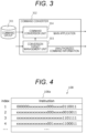
- FIG. 3 is a diagram illustrating a configuration example of a command converter that generates the main application 107.
- a command group 301 which is a set of commands included in the original application is input to the command converter 302 illustrated in FIG. 3 .
- the command converter 302 includes a conversion target management unit 303 and a command conversion unit 304.
- the conversion target management unit 303 determines, as a target command, a command designated by an instruction from the outside, and generates an extension command corresponding to the target command.
- the generation method of the extension command is similar to the generation method by the extension command generation unit 202.
- the conversion target management unit 303 notifies the command conversion unit 304 of the target command and the extension command. Further, the conversion target management unit 303 outputs information indicating the target command as the unauthorized command information 108, and stores the information in the main storage unit 102 of the control device 101 in FIG. 1 . Accordingly, in a case where the same command as the target command indicated by the unauthorized command information 108 is executed by the CPU 103, since the executed execution command is not an extension command, it is possible to determine that the execution command is an unauthorized command.
- the command conversion unit 304 replaces the target command included in the command group 301 with the extension command notified from the conversion target management unit 303.
- the command conversion unit 304 outputs, as the main application 107, the command group 301 in which the target command is replaced with the extension command and stores the command group 301 in the main storage unit 102 of the control device 101 of FIG. 1 .
- the command converter 302 may be realized by dedicated hardware, or may be realized by software in a computer such as a personal computer.
- FIG. 4 is a diagram illustrating a configuration example of the unauthorized command information 108.
- the unauthorized command information 108 illustrated in FIG. 4 indicates a target command (instruction) 108a for each index for specifying the target command.
- the target command 108a is 32-bit data in the example of FIG. 4 .
- values other than the feature portion may be indicated by an indefinite value (in FIG. 4 , "x"), but the feature portion indicates an actual value of "0" or "1".
- a 31st bit to a 25th bit, a 14th bit to a 12th bit, and a 6th bit to a 0th bit are bits for designating the calculation method.
- the arrangement of the bits illustrated in FIG. 4 is merely an example, and the bits for designating the calculation method are changed in accordance with a command set architecture to be applied or the like.
- FIG. 5 is a diagram illustrating a configuration example of the command monitoring unit 104 illustrated in FIG. 1 .
- the command monitoring unit 104 illustrated in FIG. 5 includes command comparison units 501 to 503 and an OR circuit 504.
- the command comparison unit is provided for each type of the extension command.
- the example of FIG. 5 illustrates the command monitoring unit 104 in a case where the target commands with the indexes 1 to 3 in FIG. 4 are converted into the extension commands.
- the number of command comparison units is three in FIG. 5
- the number of command comparison units is not limited to three in practice, and is increased or decreased in accordance with the type of the extension command.
- Pieces of different unauthorized command information 1 to 3 are input to and retained in the command comparison units 501 to 503.
- the pieces of unauthorized command information 1 to 3 indicate the target commands with the indexes 1 to 3, respectively.
- the execution command information is input from the CPU 103 to each of the command comparison units 501 to 503.
- Each of the command comparison units 501 to 503 compares the execution command indicated by the execution command information with the target command indicated by the retained unauthorized command information, and determines whether or not all the values of the feature portions are the same. In a case where all the values of the feature portions are the same, each of the command comparison units 501 to 503 determines that the execution command is an unauthorized command. In a case where the issued command is an unauthorized command, each of the command comparison units 501 to 503 outputs, as an abnormality detection signal indicating that an abnormality is detected, an H-level signal having a value of "1" to the OR circuit 504.
- the OR circuit 504 outputs, as an abnormality notification signal and an output stop signal, the abnormality detection signal to the command monitoring unit 104 and the output control unit 105.
- FIGS. 6 to 8 are diagrams illustrating configuration examples of the command comparison units 501 to 503 in FIG. 5 .
- FIG. 6 illustrates a configuration example of the command comparison unit 501.
- the command comparison unit 501 is a command comparison unit corresponding to the unauthorized command information 1 with an index of 1 in FIG. 4 , and includes a 6-bit comparison unit 602, a 3-bit comparison unit 603, and a 7-bit comparison unit 604 which are comparators for comparing bits of portions different from each other in the execution command and the target command, and an AND circuit 605.
- the 6-bit comparison unit 602 compares a 31st bit to a 25th bit of the target command indicated by the unauthorized command information 108 with a 31st bit to a 25th bit of the execution command indicated by the execution command information, and outputs an abnormality notification signal to the AND circuit 605 in a case where all the values coincide.
- the 3-bit comparison unit 603 compares a 14th bit to a 12th bit of the target command with a 14th bit to a 12th bit of the execution command, and outputs an abnormality notification signal to the AND circuit 605 in a case where all the values coincide.
- the 7-bit comparison unit 604 compares a 6th bit to a 0th bit of the unauthorized command with a 6th bit to a 0th bit of the execution command information, and outputs an abnormality notification signal to the AND circuit 605 in a case where all the values coincide.
- the AND circuit 605 outputs the abnormality detection signal as the comparison result.
- FIG. 7 illustrates a configuration example of the command comparison unit 502.
- the command comparison unit 502 is a command comparison unit corresponding to the unauthorized command information 2 with an index of 2 in FIG. 4 , and has a configuration in which the 6-bit comparison unit 602 is removed from the command comparison unit 501 illustrated in FIG. 6 .
- the command comparison unit 502 outputs the abnormality notification signal in a case where the 14th bit to the 12th bit between the target command and the execution command coincide and the 6th bit to the 0th bit in the target command and the execution command coincide.
- FIG. 8 illustrates a configuration example of the command comparison unit 503.
- the command comparison unit 503 is a command comparison unit corresponding to the unauthorized command information with an index of 3 in FIG. 4 , and has a configuration in which the 3-bit comparison unit 603 and the AND circuit 605 are removed from the command comparison unit 502 illustrated in FIG. 7 .
- the command comparison unit 503 outputs the abnormality notification signal in a case where the 6th bit to the 0th bit between the target command and the execution command coincide.
- the main storage unit 102 stores the main application 107 and the unauthorized command information 108.
- the main application 107 is an extension program obtained by converting the target command that is at least a part of the command included in the predetermined program into the extension command.
- the unauthorized command information 108 indicates the target command.
- the command monitoring unit 104 compares the execution command which is the command executed by the CPU 103 with the target command indicated by the unauthorized command information 108, and determines whether or not the execution command is the unauthorized command based on the comparison result.
- the CPU 103 has an extended configuration for processing the extension command as the command equivalent to the target command.
- the extension program it is possible to handle the extension program as being equivalent to the original program.
- the processor is designed in accordance with the extension command. Thus, it is possible to reduce the restriction on the command available as the extension command.
- the command monitoring unit 104 includes the comparators 602 to 604 that compare bits of feature portions having different values between the target command and the extension command in the execution command and the target command.
- the present embodiment is different from the first embodiment in a configuration of a command monitoring unit 104.
- the command monitoring unit 104 includes a plurality of command comparison units having a common configuration, and changes a portion to be compared between a target command and an execution command in accordance with a type of the target command.
- an unauthorized command information 108 includes the type of the target command.
- FIG. 9 is a diagram illustrating a configuration example of the unauthorized command information 108 including a type of a command.
- the unauthorized command information 108 illustrated in FIG. 9 indicates a target command 108a and a type (Type) 108b of the target command 108a for each index.
- the target command 108a is equivalent to the target command 108a illustrated in FIG. 4 .
- FIG. 10 is a diagram illustrating a configuration example of the command monitoring unit 104 of the present embodiment.
- the command monitoring unit 104 illustrated in FIG. 10 includes one or a plurality of command comparison units 1001 and an OR circuit 504. In a case where there are a plurality of command comparison units 1001, the configurations thereof are common.
- the example of FIG. 10 illustrates the command monitoring unit 104 in a case where target commands with indexes 1 to 3 in FIG. 9 are converted into extension commands.
- there are three command comparison units 1001 but the number of command comparison units 1001 is not limited to three in practice, and is increased or decreased in accordance with the type of the extension command.
- Pieces of different unauthorized command information 1 to 3 are input to and retained in the command comparison units 1001. Further, execution command information from the CPU 103 is input to each command comparison unit 1001.
- Each command comparison unit 1001 compares the execution command indicated by the execution command information with the target command indicated by the retained unauthorized command information, and determines whether or not all values of the feature portions are the same. In a case where all the values of the feature portions are the same, each command comparison unit 1001 determines that the execution command is an unauthorized command. In a case where the issued command is an unauthorized command, each of the command comparison units 1001 outputs, as an abnormality detection signal indicating that an abnormality is detected, an H-level signal having a value of "1" to the OR circuit 504.
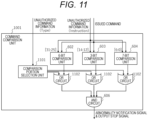
- FIG. 11 is a diagram illustrating a configuration example of the command comparison unit 1001.
- the command comparison unit 1001 illustrated in FIG. 11 further includes a comparison portion selection unit 1101 and a plurality of OR circuits 1102 in addition to the configuration of the command comparison unit 501 illustrated in FIG. 6 .
- the OR circuits 1102 are provided to correspond to a 6-bit comparison unit 602, a 3-bit comparison unit 603, and a 7-bit comparison unit 604, and are connected to an output terminal of the corresponding comparison unit. Accordingly, in the example of FIG. 11 , there are three OR circuits 1102.
- the type 108b of the unauthorized command information 108 is input to the comparison portion selection unit 1101.
- the comparison portion selection unit 1101 determines which of the 6-bit comparison unit 602, the 3-bit comparison unit 603, and the 7-bit comparison unit 604 is used as a use comparator to be used for determining whether or not the execution command is an unauthorized command in accordance with the type 108b of the command.
- the comparison portion selection unit 1101 outputs an L-level signal having a value of "0" to the OR circuit 1102 corresponding to the use comparison unit, and outputs an H-level signal having a value of "1" to the OR circuit 1102 corresponding to the comparator which is not the use comparator.
- the H-level signal is constantly output from the OR circuit 1102 corresponding to the comparator that is not the use comparator, and the H-level signal is output from the OR circuit 1102 corresponding to the use comparator in a case where the abnormality detection signal (H-level signal) is output from the use comparator. Accordingly, in a case where the abnormality detection signal is output from the use comparator, the abnormality detection signal is output as the comparison result from an AND circuit 605.
- the comparator used to determine whether or not the execution command is an unauthorized command is selected in accordance with the type of the target command.
- the configuration of the command monitoring unit 104 since it is not necessary to change the configuration of the command monitoring unit 104 in accordance with the type of the target command, it is not necessary to change the configuration of the command monitoring unit 104 even though a main application 107 or the like is changed. Accordingly, it is possible to detect the falsification of the program at an early stage while the update and replacement speed of the main application are maintained.
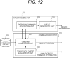
- FIG. 12 is a diagram illustrating configurations of a circuit generator 201 and a command converter 302 of the present embodiment.
- the circuit generator 201 and the command converter 302 are connected to communicate with each other.
- a conversion target management unit 303 of the command converter 302 retains target command information indicating a target command, transmits the target command information to an extension command generation unit 202 of the circuit generator 201 via a command conversion unit 304, and outputs the target command information as unauthorized command information 108.
- the extension command generation unit 202 generates an extension command based on the target command information.
- the circuit generation unit 203 designs a CPU having an extended configuration for processing the extension command as a command equivalent to the target command based on the extension command, and outputs design information.
- the extension command generation unit 202 notifies the command conversion unit 304 of command conversion information indicating the extension command and the target command.
- the command conversion unit 304 replaces the target command included in the command group 301 with the extension command indicated by the command conversion information.
- the command conversion unit 304 outputs, as a main application 107, the command group 301 in which the target command is replaced with the extension command.
- the extension command is generated based on the target command, and the CPU 103 is designed based on the extension command.
- the CPU 103 is designed based on the extension command.
- a command to be converted is determined in accordance with a command tendency by a main application 107.
- FIG. 13 is a diagram illustrating a configuration example of a circuit generator 201 and a command converter 302 of the present embodiment.
- the configuration illustrated in FIG. 13 is different from the configuration illustrated in FIG. 12 in that the command converter 302 further includes a conversion target determination unit 1301.
- a command group 301 is input to the conversion target determination unit 1301.
- the conversion target determination unit 1301 determines a target command from the command group 301 according to a predetermined determination condition.
- the determination condition is, for example, a condition related to a use frequency of each command included in the command group 301 in an original application. More specifically, the determination condition is a command whose use frequency is equal to or higher than a threshold value, or a predetermined number of commands in descending order of use frequency.
- the use frequency may be an appearance frequency in a source code of the original application, or may be an execution frequency when the original application is executed by a personal computer or an actual control device 101. Note that, the determination condition is not limited to the condition related to the use frequency, and may be a command corresponding to a predetermined priority order.
- the conversion target determination unit 1301 determines a command conforming to the determination condition as a target command, and outputs target command information indicating the target command to an extension command generation unit 202 and a conversion target management unit 303.
- the extension command generation unit 202 generates an extension command based on the target command information from the conversion target determination unit 1301, and outputs extension command information indicating the extension command to the command conversion unit 304.
- the conversion target management unit 303 outputs the target command information from the conversion target determination unit 1301 to the command conversion unit 304, and outputs the target command information as unauthorized command information 108.
- the command conversion unit 304 replaces the target command included in the command group 301 with the extension command indicated by the extension command information.
- the command conversion unit 304 outputs, as a main application 107, the command group 301 in which the target command is replaced with the extension command.
- the other processing is similar to the processing of the third embodiment.
- FIG. 14 is a diagram illustrating another configuration example of the circuit generator 201 and the command converter 302 of the present embodiment.
- the target command indicated by the target command information retained in advance by the conversion target management unit 303 is converted into the extension command.
- the conversion target determination unit 1301 determines the command conforming to the determination condition as the target command, and outputs first target command information indicating the target command to the extension command generation unit 202 and the conversion target management unit 303.
- the conversion target management unit 303 retains second target command information indicating the target command, and transmits the second target command information and the first target command information from conversion target determination unit 1301 to the extension command generation unit 202 of the circuit generator 201 via the command conversion unit 304, and outputs the second target command information and the first target command information as the unauthorized command information 108.
- the extension command generation unit 202 generates the extension command based on the first target command information from the conversion target determination unit 1301 and the second target command information from the conversion target management unit 303, and notifies the command conversion unit 304 of the command conversion information indicating the extension command and the target command indicated by the first target command information and the second target command information.
- the command conversion unit 304 replaces the target command included in the command group 301 with the extension command indicated by the command conversion information.
- the command conversion unit 304 outputs, as a main application 107, the command group 301 in which the target command is replaced with the extension command.
- the other processing is similar to the processing of the third embodiment.
- the target command includes the command conforming to the predetermined determination condition among the commands included in the command group 301 of the original application.
- the determination condition relates to the use frequency of the command, it is possible to select the appropriate target command for early detection of the unauthorized command.
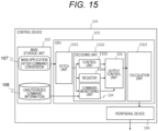
- FIG. 15 is a diagram illustrating a configuration example of a control device according to a fifth embodiment of the present disclosure.
- the CPU 103 includes a fetch unit 1501, a decoding unit 1502, and a calculation unit 1503.
- the fetch unit 1501 acquires, as an execution command, a command of a main application 107.
- the decoding unit 1502 interprets an operation of the command acquired by the fetch unit 1501.
- the calculation unit 1503 executes processing according to the operation interpreted by the decoding unit 1502.
- the decoding unit 1502 includes a control unit 1505, a register 1504, a command monitoring unit 104, and an output control unit 105.
- the control unit 1505 interprets an operation of an execution command acquired by the fetch unit 1501. For example, the control unit 1505 determines a calculator to be operated according to the execution command and an operation of the calculator.
- the register 1504 outputs a value retained in a register to be used in the processing by the execution command acquired by the fetch unit 1501.
- the command monitoring unit 104 compares the execution command with the target command indicated by the unauthorized command information 108, and inputs an output stop signal to the output control unit 105 in a case where the execution command is an unauthorized command.
- the output control unit 105 stops the calculation and output by the calculation unit 1503 based on the unauthorized command by clearing a value of the signal output to the calculation unit 1503.
- the operation of the calculation unit 1503 can be stopped. Accordingly, it is possible to suppress the calculation by the unauthorized command, and it is possible to reduce power consumption. Further, since it is possible to monitor the unauthorized command without outputting a signal to the outside of the CPU 103, it is possible to suppress a transmission delay of information. Accordingly, it is possible to suppress a decrease in a frequency of the control device 101.
Landscapes
- Engineering & Computer Science (AREA)
- Computer Security & Cryptography (AREA)
- Software Systems (AREA)
- Theoretical Computer Science (AREA)
- General Engineering & Computer Science (AREA)
- Computer Hardware Design (AREA)
- General Physics & Mathematics (AREA)
- Physics & Mathematics (AREA)
- Virology (AREA)
- Health & Medical Sciences (AREA)
- General Health & Medical Sciences (AREA)
- Storage Device Security (AREA)
- Executing Machine-Instructions (AREA)
- Devices For Executing Special Programs (AREA)
Abstract
Description
- The present disclosure relates to a control device, an unauthorized command detection method, and a program.
- In recent years, in an embedded system that supports an industrial electronic control device, a load has been increased due to improvement in control performance, tightening of environmental regulations, addition of new calculation processing accompanying autonomy of devices, and the like.
- Further, application of autonomous control to a social system has been progressing, and it is necessary to operate an autonomous body such as a self-propelled robot in an area where an unspecified number of people or devices enter. In such a situation, there is a problem that a risk of attack on the autonomous body increases. Thus, a mechanism for preventing the attack on the autonomous body in advance or suppressing an influence of the attack is required. As means for attacking the autonomous body, falsification of a program for controlling the autonomous body has been known.
-
PTL 1 discloses a technique capable of detecting falsification of a program. In this technique, a behavior pattern of a normal program is recorded as a basic pattern, and then a behavior of the program is recorded during the execution of the program. When the behavior pattern is determined from the behavior of the program, it is confirmed whether or not the behavior pattern coincides with the basic pattern. When these patterns do not coincide with each other, it is determined that the program has been falsified. - PTL 1:
JP 2017-505944 A - However, in a case where the behavior pattern of the program is monitored as in the technique described in
PTL 1, since the falsification of the program is detected after a series of operations of the program is performed, there is a problem that it takes a long time from the execution of the falsified program to the detection of the falsification. Further, in order to monitor the behavior pattern, it is necessary to record the behavior pattern of the program being executed, read the behavior pattern and the basic pattern recorded in advance, and compare these patterns. Thus, there is also a problem that a load related to monitoring is large. Thus, resources available for original functions such as autonomous control are reduced. Note that, it is also conceivable to compare the behavior pattern with the basic pattern while the original function is stopped. However, in this case, a time required for detecting the falsification becomes longer, and there is a concern that a time required from the occurrence of an abnormal operation to the handling cannot be satisfied. - An object of the present invention is to provide a control device, an unauthorized command detection method, and a program capable of detecting falsification of a program at an early stage while reducing a load.
- A control device according to one aspect of the present disclosure includes a processor, a main storage unit that stores an extension program executed by the processor and unauthorized command information indicating a target command that is at least a part of commands included in a predetermined program, the extension program being obtained by converting the target command into an extension command, and a command monitoring unit that compares an execution command that is a command executed by the processor with the target command indicated by the unauthorized command information, and determines whether or not the execution command is an unauthorized command based on the comparison result.
- According to the present invention, it is possible to detect the falsification of the program at an early stage while reducing the load.
-
- [
FIG. 1] FIG. 1 is a diagram illustrating a configuration example of a control device according to a first embodiment of the present disclosure. - [
FIG. 2] FIG. 2 is a diagram illustrating a configuration example of a circuit generator according to the first embodiment of the present disclosure. - [
FIG. 3] FIG. 3 is a diagram illustrating a configuration example of a command converter according to the first embodiment of the present disclosure. - [
FIG. 4] FIG. 4 is a diagram illustrating a configuration example of unauthorized command information according to the first embodiment of the present disclosure. - [
FIG. 5] FIG. 5 is a diagram illustrating a configuration example of a command monitoring unit according to the first embodiment of the present disclosure. - [
FIG. 6] FIG. 6 is a diagram illustrating a configuration example of a command comparison unit according to the first embodiment of the present invention. - [
FIG. 7] FIG. 7 is a diagram illustrating another configuration example of the command comparison unit according to the first embodiment of the present disclosure. - [
FIG. 8] FIG. 8 is a diagram illustrating still another configuration example of the command comparison unit according to the first embodiment of the present disclosure. - [
FIG. 9] FIG. 9 is a diagram illustrating a configuration example of unauthorized command information according to a second embodiment of the present disclosure. - [
FIG. 10] FIG. 10 is a diagram illustrating a configuration example of a command monitoring unit according to the second embodiment of the present disclosure. - [
FIG. 11] FIG. 11 is a diagram illustrating a configuration example of a command comparison unit according to the second embodiment of the present disclosure. - [
FIG. 12] FIG. 12 is a diagram illustrating a configuration example of a circuit generator and a command converter according to a third embodiment of the present disclosure. - [
FIG. 13] FIG. 13 is a diagram illustrating a configuration example of a circuit generator and a command converter according to a fourth embodiment of the present disclosure. - [
FIG. 14] FIG. 14 is a diagram illustrating another configuration example of the circuit generator and the command converter according to the fourth embodiment of the present disclosure. - [
FIG. 15] FIG. 15 is a diagram illustrating a configuration example of a control device according to a fifth embodiment of the present disclosure. - Hereinafter, embodiments of the present disclosure will be described with reference to the drawings. Note that, in the configuration of each embodiment, the same portions or portions having similar functions share the same reference signs in different drawings, and redundant descriptions may be omitted.
-
FIG. 1 is a diagram illustrating a configuration example of a control device according to a first embodiment of the present disclosure. Acontrol device 101 illustrated inFIG. 1 includes amain storage unit 102, aCPU 103, acommand monitoring unit 104, anoutput control unit 105, and aperipheral device 106. - The
main storage unit 102 stores a main application program (hereinafter, abbreviated as a main application) 107 andunauthorized command information 108. Themain application 107 is an extension program obtained by converting a target command that is at least a part of a command included in an original application program (hereinafter, abbreviated as an original application) that is a predetermined program into an extension command to be described later. The original application and themain application 107 are, for example, control programs for controlling a controlled target such as an autonomous body that grasps an own situation and operates. Theunauthorized command information 108 is information for detecting falsification of themain application 107, and is information indicating a target command which is a command before conversion of the extension command included in themain application 107. - The
CPU 103 is a processor that reads themain application 107 stored in themain storage unit 102, executes each command included in the readmain application 107, and performs various calculations. Specifically, theCPU 103 includes a register that retains data to be used for calculation, a calculator that executes calculation by using the data retained in the register, and the like. TheCPU 103 acquires the command of themain application 107 from themain storage unit 102, deciphers a bit string of the command, determines the selection of the register and the calculator corresponding to the command and an operation of the calculator, and executes the calculation corresponding to the command. - In a case where the calculation result is output to an outside of the
control device 101 such as the controlled target, theCPU 103 outputs, as output data, the calculation result to theoutput control unit 105. Further, theCPU 103 outputs execution command information indicating an execution command which is an executed command to thecommand monitoring unit 104. - The
command monitoring unit 104 acquiresunauthorized command information 108 from themain storage unit 102, and acquires the execution command information from theCPU 103. Thecommand monitoring unit 104 compares the target command indicated by theunauthorized command information 108 with the execution command indicated by the execution command information, and determines whether or not the execution command is an unauthorized command. Specifically, in a case where a value of a feature portion indicating a feature of the command coincides with any of target commands indicated by the execution command by theunauthorized command information 108, thecommand monitoring unit 104 determines that the execution command is an unauthorized command and determines that the program is falsified. - In a case where the execution command is the unauthorized command, the
command monitoring unit 104 outputs an output stop signal to theoutput control unit 105, stops the output of theCPU 103, and outputs an abnormality notification signal to theperipheral device 106. - The
output control unit 105 controls the output of the output data of theCPU 103 to the outside. Specifically, theoutput control unit 105 transmits the output data from theCPU 103 to theperipheral device 106 in a case where the output stop signal is not received from thecommand monitoring unit 104, and stops the transmission of the output data in a case where the output stop signal is received. - The
peripheral device 106 is an output unit that outputs the output data from theoutput control unit 105 and the abnormality notification signal from thecommand monitoring unit 104 to the outside of thecontrol device 101. The transmission method of the output data is, for example, communication via a wireless or wired network. Examples of the transmission method of the abnormality notification signal include lighting of an LED or the like, message communication via a wireless or wired network, and output of ON and OFF signals. - The
CPU 103 has an extended configuration for executing an extension command in themain application 107. The extended configuration is a configuration for processing the extension command as a command equivalent to the target command before conversion. The equivalent command is, for example, a command to output an equivalent result. -
FIG. 2 is a diagram illustrating a configuration of a circuit generator that designs theCPU 103 having the extended configuration. Thecircuit generator 201 illustrated inFIG. 2 includes an extensioncommand generation unit 202 and acircuit generation unit 203. - Target command information indicating a target command to be converted into an extension command is input to the extension
command generation unit 202. The extensioncommand generation unit 202 converts the target command indicated by the target command information into the extension command and notifies thecircuit generation unit 203 of the extension command. The extension command is a command to replace bits for designating a calculation method (specifically, the calculator and the operation of the calculator) in the target command with a value for the extension command. Thus, bits for designating a register, an address, and an immediate value of the extension command inherit bits of an original target command. Note that, the bit to be replaced is different for each type of the command. Further, the bits for designating the calculation method are feature portions representing the features of the above-described command. - The
circuit generation unit 203 designs a CPU having an extended configuration for processing the extension command notified from the extensioncommand generation unit 202 as the command equivalent to the target command. Specifically, thecircuit generation unit 203 designs the CPU having the extended configuration that executes processing according to the calculation method designated by the extension command in accordance with the type of the extension command, and outputs the design information. The CPU generated according to the design information is mounted on thecontrol device 101 as theCPU 103. - In the present embodiment, the
circuit generation unit 203 generates design information of a CPU having an extension function by rearranging the design information of the existing CPU that does not need to execute the extension command in accordance with the extension command. In this case, a main recombination portion of the design information is a portion of the circuit that outputs a control signal of each calculator. Note that, the design information of the existing CPU may be stored in advance in thecircuit generator 201 or may be input from an outside. Further, thecircuit generation unit 203 may be realized by dedicated hardware, or may be realized by software in a computer such as a personal computer. - Note that, as the number of target commands increases, since the number of types of extension commands available in an original function of the CPU 103 (for example, a function of controlling the controlled target) decreases, it is desirable to appropriately set the number of target commands in accordance with the number of commands of the original application and other restrictions.
-
FIG. 3 is a diagram illustrating a configuration example of a command converter that generates themain application 107. Acommand group 301 which is a set of commands included in the original application is input to thecommand converter 302 illustrated inFIG. 3 . Further, thecommand converter 302 includes a conversiontarget management unit 303 and acommand conversion unit 304. - The conversion
target management unit 303 determines, as a target command, a command designated by an instruction from the outside, and generates an extension command corresponding to the target command. The generation method of the extension command is similar to the generation method by the extensioncommand generation unit 202. The conversiontarget management unit 303 notifies thecommand conversion unit 304 of the target command and the extension command. Further, the conversiontarget management unit 303 outputs information indicating the target command as theunauthorized command information 108, and stores the information in themain storage unit 102 of thecontrol device 101 inFIG. 1 . Accordingly, in a case where the same command as the target command indicated by theunauthorized command information 108 is executed by theCPU 103, since the executed execution command is not an extension command, it is possible to determine that the execution command is an unauthorized command. - In a case where the target command notified from the conversion
target management unit 303 is included in thecommand group 301, thecommand conversion unit 304 replaces the target command included in thecommand group 301 with the extension command notified from the conversiontarget management unit 303. Thecommand conversion unit 304 outputs, as themain application 107, thecommand group 301 in which the target command is replaced with the extension command and stores thecommand group 301 in themain storage unit 102 of thecontrol device 101 ofFIG. 1 . Note that, thecommand converter 302 may be realized by dedicated hardware, or may be realized by software in a computer such as a personal computer. -
FIG. 4 is a diagram illustrating a configuration example of theunauthorized command information 108. Theunauthorized command information 108 illustrated inFIG. 4 indicates a target command (instruction) 108a for each index for specifying the target command. Thetarget command 108a is 32-bit data in the example ofFIG. 4 . In theunauthorized command information 108, among values of bits of thetarget command 108a, values other than the feature portion (the bits for designating the calculation method) may be indicated by an indefinite value (inFIG. 4 , "x"), but the feature portion indicates an actual value of "0" or "1". - For example, in a first command (index = 1), a 31st bit to a 25th bit, a 14th bit to a 12th bit, and a 6th bit to a 0th bit are bits for designating the calculation method. In a case where the command coincides with the execution command with all of these values, it is determined that the execution command is an unauthorized command. Note that, the bits for designating the calculation method are different depending on the type of the command, and for example, a third command (index = 3) designates the calculation method with values from a 6th bit to a 0th bit. Note that, the arrangement of the bits illustrated in
FIG. 4 is merely an example, and the bits for designating the calculation method are changed in accordance with a command set architecture to be applied or the like. -
FIG. 5 is a diagram illustrating a configuration example of thecommand monitoring unit 104 illustrated inFIG. 1 . Thecommand monitoring unit 104 illustrated inFIG. 5 includescommand comparison units 501 to 503 and an ORcircuit 504. The command comparison unit is provided for each type of the extension command. The example ofFIG. 5 illustrates thecommand monitoring unit 104 in a case where the target commands with theindexes 1 to 3 inFIG. 4 are converted into the extension commands. Thus, although the number of command comparison units is three inFIG. 5 , the number of command comparison units is not limited to three in practice, and is increased or decreased in accordance with the type of the extension command. - Pieces of different
unauthorized command information 1 to 3 are input to and retained in thecommand comparison units 501 to 503. Here, the pieces ofunauthorized command information 1 to 3 indicate the target commands with theindexes 1 to 3, respectively. Further, the execution command information is input from theCPU 103 to each of thecommand comparison units 501 to 503. - Each of the
command comparison units 501 to 503 compares the execution command indicated by the execution command information with the target command indicated by the retained unauthorized command information, and determines whether or not all the values of the feature portions are the same. In a case where all the values of the feature portions are the same, each of thecommand comparison units 501 to 503 determines that the execution command is an unauthorized command. In a case where the issued command is an unauthorized command, each of thecommand comparison units 501 to 503 outputs, as an abnormality detection signal indicating that an abnormality is detected, an H-level signal having a value of "1" to theOR circuit 504. - In a case where the abnormality detection signal is output from at least one of the
command comparison units 501 to 503, theOR circuit 504 outputs, as an abnormality notification signal and an output stop signal, the abnormality detection signal to thecommand monitoring unit 104 and theoutput control unit 105. -
FIGS. 6 to 8 are diagrams illustrating configuration examples of thecommand comparison units 501 to 503 inFIG. 5 . -
FIG. 6 illustrates a configuration example of thecommand comparison unit 501. Thecommand comparison unit 501 is a command comparison unit corresponding to theunauthorized command information 1 with an index of 1 inFIG. 4 , and includes a 6-bit comparison unit 602, a 3-bit comparison unit 603, and a 7-bit comparison unit 604 which are comparators for comparing bits of portions different from each other in the execution command and the target command, and an ANDcircuit 605. - The 6-
bit comparison unit 602 compares a 31st bit to a 25th bit of the target command indicated by theunauthorized command information 108 with a 31st bit to a 25th bit of the execution command indicated by the execution command information, and outputs an abnormality notification signal to the ANDcircuit 605 in a case where all the values coincide. The 3-bit comparison unit 603 compares a 14th bit to a 12th bit of the target command with a 14th bit to a 12th bit of the execution command, and outputs an abnormality notification signal to the ANDcircuit 605 in a case where all the values coincide. The 7-bit comparison unit 604 compares a 6th bit to a 0th bit of the unauthorized command with a 6th bit to a 0th bit of the execution command information, and outputs an abnormality notification signal to the ANDcircuit 605 in a case where all the values coincide. - In a case where the abnormality detection signals are output from all the comparison units (6-
bit comparison unit 602, 3-bit comparison unit 603, and 7-bit comparison unit 604), the ANDcircuit 605 outputs the abnormality detection signal as the comparison result. -
FIG. 7 illustrates a configuration example of thecommand comparison unit 502. Thecommand comparison unit 502 is a command comparison unit corresponding to theunauthorized command information 2 with an index of 2 inFIG. 4 , and has a configuration in which the 6-bit comparison unit 602 is removed from thecommand comparison unit 501 illustrated inFIG. 6 . Thus, thecommand comparison unit 502 outputs the abnormality notification signal in a case where the 14th bit to the 12th bit between the target command and the execution command coincide and the 6th bit to the 0th bit in the target command and the execution command coincide. -
FIG. 8 illustrates a configuration example of thecommand comparison unit 503. Thecommand comparison unit 503 is a command comparison unit corresponding to the unauthorized command information with an index of 3 inFIG. 4 , and has a configuration in which the 3-bit comparison unit 603 and the ANDcircuit 605 are removed from thecommand comparison unit 502 illustrated inFIG. 7 . Thus, thecommand comparison unit 503 outputs the abnormality notification signal in a case where the 6th bit to the 0th bit between the target command and the execution command coincide. - As described above, according to the present embodiment, the
main storage unit 102 stores themain application 107 and theunauthorized command information 108. Themain application 107 is an extension program obtained by converting the target command that is at least a part of the command included in the predetermined program into the extension command. Theunauthorized command information 108 indicates the target command. Thecommand monitoring unit 104 compares the execution command which is the command executed by theCPU 103 with the target command indicated by theunauthorized command information 108, and determines whether or not the execution command is the unauthorized command based on the comparison result. - With the above configuration, it is possible to monitor the falsification of the program in units of commands when the program is executed. Thus, it is not necessary to record, read, and compare action patterns, and thus, it is possible to reduce a load related to monitoring processing. Further, since the falsification of the program can be detected without waiting for the confirmation of the action pattern, the time required for detecting the falsification can be shortened. Accordingly, it is possible to detect the falsification of the program at an early stage while reducing the load.
- Further, in the present embodiment, the
CPU 103 has an extended configuration for processing the extension command as the command equivalent to the target command. Thus, it is possible to handle the extension program as being equivalent to the original program. - Further, in the present embodiment, the processor is designed in accordance with the extension command. Thus, it is possible to reduce the restriction on the command available as the extension command.
- Further, in the present embodiment, the
command monitoring unit 104 includes thecomparators 602 to 604 that compare bits of feature portions having different values between the target command and the extension command in the execution command and the target command. Thus, since it is possible to configure thecommand monitoring unit 104 in accordance with the extension command, it is possible to reduce the load of the monitoring processing. - The present embodiment is different from the first embodiment in a configuration of a
command monitoring unit 104. Specifically, thecommand monitoring unit 104 includes a plurality of command comparison units having a common configuration, and changes a portion to be compared between a target command and an execution command in accordance with a type of the target command. Thus, anunauthorized command information 108 includes the type of the target command. -
FIG. 9 is a diagram illustrating a configuration example of theunauthorized command information 108 including a type of a command. Theunauthorized command information 108 illustrated inFIG. 9 indicates atarget command 108a and a type (Type) 108b of thetarget command 108a for each index. Thetarget command 108a is equivalent to thetarget command 108a illustrated inFIG. 4 . -
FIG. 10 is a diagram illustrating a configuration example of thecommand monitoring unit 104 of the present embodiment. Thecommand monitoring unit 104 illustrated inFIG. 10 includes one or a plurality ofcommand comparison units 1001 and an ORcircuit 504. In a case where there are a plurality ofcommand comparison units 1001, the configurations thereof are common. The example ofFIG. 10 illustrates thecommand monitoring unit 104 in a case where target commands withindexes 1 to 3 inFIG. 9 are converted into extension commands. Thus, inFIG. 10 , there are threecommand comparison units 1001, but the number ofcommand comparison units 1001 is not limited to three in practice, and is increased or decreased in accordance with the type of the extension command. - Pieces of different
unauthorized command information 1 to 3 are input to and retained in thecommand comparison units 1001. Further, execution command information from theCPU 103 is input to eachcommand comparison unit 1001. - Each
command comparison unit 1001 compares the execution command indicated by the execution command information with the target command indicated by the retained unauthorized command information, and determines whether or not all values of the feature portions are the same. In a case where all the values of the feature portions are the same, eachcommand comparison unit 1001 determines that the execution command is an unauthorized command. In a case where the issued command is an unauthorized command, each of thecommand comparison units 1001 outputs, as an abnormality detection signal indicating that an abnormality is detected, an H-level signal having a value of "1" to theOR circuit 504. -
FIG. 11 is a diagram illustrating a configuration example of thecommand comparison unit 1001. Thecommand comparison unit 1001 illustrated inFIG. 11 further includes a comparisonportion selection unit 1101 and a plurality of ORcircuits 1102 in addition to the configuration of thecommand comparison unit 501 illustrated inFIG. 6 . The ORcircuits 1102 are provided to correspond to a 6-bit comparison unit 602, a 3-bit comparison unit 603, and a 7-bit comparison unit 604, and are connected to an output terminal of the corresponding comparison unit. Accordingly, in the example ofFIG. 11 , there are three ORcircuits 1102. - The
type 108b of theunauthorized command information 108 is input to the comparisonportion selection unit 1101. The comparisonportion selection unit 1101 determines which of the 6-bit comparison unit 602, the 3-bit comparison unit 603, and the 7-bit comparison unit 604 is used as a use comparator to be used for determining whether or not the execution command is an unauthorized command in accordance with thetype 108b of the command. As a selection signal for selecting the use comparator, the comparisonportion selection unit 1101 outputs an L-level signal having a value of "0" to theOR circuit 1102 corresponding to the use comparison unit, and outputs an H-level signal having a value of "1" to theOR circuit 1102 corresponding to the comparator which is not the use comparator. - Accordingly, the H-level signal is constantly output from the
OR circuit 1102 corresponding to the comparator that is not the use comparator, and the H-level signal is output from theOR circuit 1102 corresponding to the use comparator in a case where the abnormality detection signal (H-level signal) is output from the use comparator. Accordingly, in a case where the abnormality detection signal is output from the use comparator, the abnormality detection signal is output as the comparison result from an ANDcircuit 605. - As described above, according to the present embodiment, the comparator used to determine whether or not the execution command is an unauthorized command is selected in accordance with the type of the target command. Thus, since it is not necessary to change the configuration of the
command monitoring unit 104 in accordance with the type of the target command, it is not necessary to change the configuration of thecommand monitoring unit 104 even though amain application 107 or the like is changed. Accordingly, it is possible to detect the falsification of the program at an early stage while the update and replacement speed of the main application are maintained. - In the present embodiment, an example in which an extension command and a CPU are designed in accordance with target command information will be described.
-
FIG. 12 is a diagram illustrating configurations of acircuit generator 201 and acommand converter 302 of the present embodiment. In the present embodiment, as illustrated inFIG. 12 , thecircuit generator 201 and thecommand converter 302 are connected to communicate with each other. - A conversion
target management unit 303 of thecommand converter 302 retains target command information indicating a target command, transmits the target command information to an extensioncommand generation unit 202 of thecircuit generator 201 via acommand conversion unit 304, and outputs the target command information asunauthorized command information 108. - The extension
command generation unit 202 generates an extension command based on the target command information. Thecircuit generation unit 203 designs a CPU having an extended configuration for processing the extension command as a command equivalent to the target command based on the extension command, and outputs design information. - Further, the extension
command generation unit 202 notifies thecommand conversion unit 304 of command conversion information indicating the extension command and the target command. In a case where the target command indicated by the command conversion information is included in acommand group 301, thecommand conversion unit 304 replaces the target command included in thecommand group 301 with the extension command indicated by the command conversion information. Thecommand conversion unit 304 outputs, as amain application 107, thecommand group 301 in which the target command is replaced with the extension command. - As described above, according to the present embodiment, the extension command is generated based on the target command, and the
CPU 103 is designed based on the extension command. Thus, since it is possible to appropriately set an extension command for monitoring the falsification of the program, it is possible to set an appropriate extension command corresponding to a tendency of a predetermined program to be used or malware to be monitored. - In the present embodiment, a command to be converted is determined in accordance with a command tendency by a
main application 107. -
FIG. 13 is a diagram illustrating a configuration example of acircuit generator 201 and acommand converter 302 of the present embodiment. The configuration illustrated inFIG. 13 is different from the configuration illustrated inFIG. 12 in that thecommand converter 302 further includes a conversiontarget determination unit 1301. - A
command group 301 is input to the conversiontarget determination unit 1301. The conversiontarget determination unit 1301 determines a target command from thecommand group 301 according to a predetermined determination condition. The determination condition is, for example, a condition related to a use frequency of each command included in thecommand group 301 in an original application. More specifically, the determination condition is a command whose use frequency is equal to or higher than a threshold value, or a predetermined number of commands in descending order of use frequency. The use frequency may be an appearance frequency in a source code of the original application, or may be an execution frequency when the original application is executed by a personal computer or anactual control device 101. Note that, the determination condition is not limited to the condition related to the use frequency, and may be a command corresponding to a predetermined priority order. - The conversion
target determination unit 1301 determines a command conforming to the determination condition as a target command, and outputs target command information indicating the target command to an extensioncommand generation unit 202 and a conversiontarget management unit 303. - The extension
command generation unit 202 generates an extension command based on the target command information from the conversiontarget determination unit 1301, and outputs extension command information indicating the extension command to thecommand conversion unit 304. - Further, the conversion
target management unit 303 outputs the target command information from the conversiontarget determination unit 1301 to thecommand conversion unit 304, and outputs the target command information asunauthorized command information 108. In a case where the target command indicated by the target conversion information is included in thecommand group 301, thecommand conversion unit 304 replaces the target command included in thecommand group 301 with the extension command indicated by the extension command information. Thecommand conversion unit 304 outputs, as amain application 107, thecommand group 301 in which the target command is replaced with the extension command. The other processing is similar to the processing of the third embodiment. -
FIG. 14 is a diagram illustrating another configuration example of thecircuit generator 201 and thecommand converter 302 of the present embodiment. In the example ofFIG. 14 , in addition to the target command determined by the conversiontarget determination unit 1301, the target command indicated by the target command information retained in advance by the conversiontarget management unit 303 is converted into the extension command. - Specifically, the conversion
target determination unit 1301 determines the command conforming to the determination condition as the target command, and outputs first target command information indicating the target command to the extensioncommand generation unit 202 and the conversiontarget management unit 303. - The conversion
target management unit 303 retains second target command information indicating the target command, and transmits the second target command information and the first target command information from conversiontarget determination unit 1301 to the extensioncommand generation unit 202 of thecircuit generator 201 via thecommand conversion unit 304, and outputs the second target command information and the first target command information as theunauthorized command information 108. - The extension
command generation unit 202 generates the extension command based on the first target command information from the conversiontarget determination unit 1301 and the second target command information from the conversiontarget management unit 303, and notifies thecommand conversion unit 304 of the command conversion information indicating the extension command and the target command indicated by the first target command information and the second target command information. In a case where the target command indicated by the command conversion information is included in acommand group 301, thecommand conversion unit 304 replaces the target command included in thecommand group 301 with the extension command indicated by the command conversion information. Thecommand conversion unit 304 outputs, as amain application 107, thecommand group 301 in which the target command is replaced with the extension command. The other processing is similar to the processing of the third embodiment. - As described above, according to the present embodiment, the target command includes the command conforming to the predetermined determination condition among the commands included in the
command group 301 of the original application. Thus, it is possible to select the appropriate target command. In particular, in the present embodiment, since the determination condition relates to the use frequency of the command, it is possible to select the appropriate target command for early detection of the unauthorized command. - In the present embodiment, an example in which a
command monitoring unit 104 is provided inside aCPU 103 will be described. -
FIG. 15 is a diagram illustrating a configuration example of a control device according to a fifth embodiment of the present disclosure. In the example ofFIG. 15 , theCPU 103 includes a fetchunit 1501, adecoding unit 1502, and acalculation unit 1503. - The fetch
unit 1501 acquires, as an execution command, a command of amain application 107. Thedecoding unit 1502 interprets an operation of the command acquired by the fetchunit 1501. Thecalculation unit 1503 executes processing according to the operation interpreted by thedecoding unit 1502. - Specifically, the
decoding unit 1502 includes acontrol unit 1505, aregister 1504, acommand monitoring unit 104, and anoutput control unit 105. Thecontrol unit 1505 interprets an operation of an execution command acquired by the fetchunit 1501. For example, thecontrol unit 1505 determines a calculator to be operated according to the execution command and an operation of the calculator. Theregister 1504 outputs a value retained in a register to be used in the processing by the execution command acquired by the fetchunit 1501. Thecommand monitoring unit 104 compares the execution command with the target command indicated by theunauthorized command information 108, and inputs an output stop signal to theoutput control unit 105 in a case where the execution command is an unauthorized command. Theoutput control unit 105 stops the calculation and output by thecalculation unit 1503 based on the unauthorized command by clearing a value of the signal output to thecalculation unit 1503. - As described above, in the present embodiment, since the unauthorized command can be monitored inside the
CPU 103, the operation of thecalculation unit 1503 can be stopped. Accordingly, it is possible to suppress the calculation by the unauthorized command, and it is possible to reduce power consumption. Further, since it is possible to monitor the unauthorized command without outputting a signal to the outside of theCPU 103, it is possible to suppress a transmission delay of information. Accordingly, it is possible to suppress a decrease in a frequency of thecontrol device 101. - The above-described embodiment of the present disclosure is an example for describing the present disclosure, and is not intended to limit the scope of the present disclosure only to the embodiment. Those skilled in the art can implement the present disclosure in various other aspects without departing from the scope of the present disclosure.
-
- 101
- control device
- 102
- main storage unit
- 103
- CPU
- 104
- command monitoring unit
- 105
- output control unit
- 106
- peripheral device
- 107
- main application program
- 108
- unauthorized command information
- 201
- circuit generator
- 201
- circuit generation unit
- 202
- extension command generation unit
- 203
- circuit generation unit
- 301
- command group
- 302
- command converter
- 303
- conversion target management unit
- 304
- command conversion unit
- 501 to 503
- command comparison unit
- 504
- OR circuit
- 602
- 6-bit comparison unit
- 603
- 3-bit comparison unit
- 604
- 7-bit comparison unit
- 605
- AND circuit
- 1001
- command comparison unit
- 1101
- comparison portion selection unit
- 1102
- OR circuit
- 1301
- conversion target determination unit
- 1501
- fetch unit
- 1502
- decoding unit
- 1503
- calculation unit
- 1504
- register
- 1505
- control unit
Claims (12)
- A control device comprising:a processor;a main storage unit that stores an extension program executed by the processor and unauthorized command information indicating a target command that is at least a part of commands included in a predetermined program, the extension program being obtained by converting the target command into an extension command; anda command monitoring unit that compares an execution command that is a command executed by the processor with the target command indicated by the unauthorized command information, and determines whether or not the execution command is an unauthorized command based on the comparison result.
- The control device according to claim 1, wherein the processor has an extended configuration for processing the extension command as a command equivalent to the target command.
- The control device according to claim 2, whereinthe extension command is created based on the target command, andthe processor is designed based on the extension command.
- The control device according to claim 1, wherein the target command includes a command conforming to a predetermined determination condition among the commands included in the predetermined program.
- The control device according to claim 4, wherein the determination condition includes a condition related to a use frequency of each command in the predetermined program.
- The control device according to claim 1, wherein the command monitoring unit includes a command comparison unit that includes a comparator that compares bits in feature portions having different values between the target command and the extension command in the execution command and the target command.
- The control device according to claim 1, wherein the command monitoring unit includesa plurality of comparators that compare bits of portions different from each other between the execution command and the target command, anda selection unit that selects a comparator to be used for determining whether or not the execution command is the unauthorized command from among the plurality of comparators in accordance with a type of the target command.
- The control device according to claim 1, wherein the command monitoring unit is provided inside the processor.
- The control device according to claim 1, wherein the command monitoring unit stops an output of the processor in a case where the execution command is the unauthorized command.
- The control device according to claim 1, wherein the extension program is a program for controlling an autonomous body.
- An unauthorized command detection method by a control device that includes a processor and a main storage unit that stores an extension program executed by the processor and unauthorized command information indicating a target command that is at least a part of commands included in a predetermined program, the extension program being obtained by converting the target command into an extension command, the method comprising:comparing execution command information indicating an execution command that is a command executed by the processor with the unauthorized command information; anddetermining whether or not the execution command is an unauthorized command based on the comparison result.
- A program causing a control device, which includes a processor and a main storage unit that stores an extension program executed by the processor and unauthorized command information indicating a target command that is at least a part of commands included in a predetermined program, the extension program being obtained by converting the target command into an extension command, to execute a procedure of:comparing execution command information indicating an execution command that is a command executed by the processor with the unauthorized command information; anddetermining whether or not the execution command is an unauthorized command based on the comparison result.
Applications Claiming Priority (2)
| Application Number | Priority Date | Filing Date | Title |
|---|---|---|---|
| JP2021055288A JP7495371B2 (en) | 2021-03-29 | 2021-03-29 | Control device, unauthorized command detection method and program |
| PCT/JP2022/006972 WO2022209420A1 (en) | 2021-03-29 | 2022-02-21 | Control device, illegal command detection method, and program |
Publications (2)
| Publication Number | Publication Date |
|---|---|
| EP4318282A1 true EP4318282A1 (en) | 2024-02-07 |
| EP4318282A4 EP4318282A4 (en) | 2025-04-02 |
Family
ID=83456021
Family Applications (1)
| Application Number | Title | Priority Date | Filing Date |
|---|---|---|---|
| EP22779647.1A Pending EP4318282A4 (en) | 2021-03-29 | 2022-02-21 | CONTROL DEVICE, METHOD FOR DETECTING ILLEGAL COMMANDS AND PROGRAM |
Country Status (4)
| Country | Link |
|---|---|
| US (1) | US20240176873A1 (en) |
| EP (1) | EP4318282A4 (en) |
| JP (1) | JP7495371B2 (en) |
| WO (1) | WO2022209420A1 (en) |
Family Cites Families (12)
| Publication number | Priority date | Publication date | Assignee | Title |
|---|---|---|---|---|
| WO2005106619A1 (en) | 2004-04-29 | 2005-11-10 | Koninklijke Philips Electronics, N.V. | Intrusion detection during program execution in a computer |
| JP5766648B2 (en) | 2012-04-26 | 2015-08-19 | 日本電信電話株式会社 | Control monitoring device, control monitoring method, and control monitoring program |
| IL242523A0 (en) | 2015-04-16 | 2016-04-21 | Yuval Elovici | Method and system for protecting computerized systems from malicious code by means of mutable instructions |
| US11074199B2 (en) * | 2016-01-27 | 2021-07-27 | Hewlett Packard Enterprise Development Lp | Securing a memory device |
| WO2017187520A1 (en) * | 2016-04-26 | 2017-11-02 | 三菱電機株式会社 | Intrusion detection device, intrusion detection method, and intrusion detection program |
| JP2018022296A (en) * | 2016-08-02 | 2018-02-08 | 株式会社日立製作所 | Supervisory control device |
| JP2018109908A (en) * | 2017-01-05 | 2018-07-12 | 富士通株式会社 | Similarity determination program, similarity determination method, and information processing apparatus |
| US10305701B2 (en) * | 2017-07-17 | 2019-05-28 | The Boeing Company | Phase-modulated signal parameter estimation using streaming calculations |
| JP7595401B2 (en) * | 2018-11-29 | 2024-12-06 | 株式会社日立製作所 | Autonomous system and control method thereof |
| EP3754526A1 (en) | 2019-06-18 | 2020-12-23 | Gemalto Sa | Method for controlling an execution flow of an application |
| US11409868B2 (en) * | 2019-09-26 | 2022-08-09 | At&T Intellectual Property I, L.P. | Ransomware detection and mitigation |
| CN112069031B (en) * | 2020-09-03 | 2023-06-23 | 中国平安财产保险股份有限公司 | Abnormality query method, device, equipment and computer readable storage medium |
-
2021
- 2021-03-29 JP JP2021055288A patent/JP7495371B2/en active Active
-
2022
- 2022-02-21 US US18/283,413 patent/US20240176873A1/en active Pending
- 2022-02-21 EP EP22779647.1A patent/EP4318282A4/en active Pending
- 2022-02-21 WO PCT/JP2022/006972 patent/WO2022209420A1/en not_active Ceased
Also Published As
| Publication number | Publication date |
|---|---|
| WO2022209420A1 (en) | 2022-10-06 |
| JP7495371B2 (en) | 2024-06-04 |
| JP2022152497A (en) | 2022-10-12 |
| EP4318282A4 (en) | 2025-04-02 |
| US20240176873A1 (en) | 2024-05-30 |
Similar Documents
| Publication | Publication Date | Title |
|---|---|---|
| KR101759008B1 (en) | Profiling code execution | |
| RU2526716C2 (en) | Heuristic code analysis method | |
| CN102652297A (en) | Arithmetic processing device, information processing device and control method thereof | |
| US8959317B2 (en) | Processor and method for saving designated registers in interrupt processing based on an interrupt factor | |
| EP3812933B1 (en) | Vulnerability evaluation apparatus | |
| CN114064430A (en) | Computer temperature abnormity processing method and system | |
| WO2018071093A1 (en) | Programmable hardware security counters | |
| EP4318282A1 (en) | Control device, illegal command detection method, and program | |
| KR20150046119A (en) | Protection scheme for embedded code | |
| JP3749233B2 (en) | Instruction execution method and apparatus in pipeline | |
| CN114826388A (en) | Novel zero-insertion-loss OLP optical line protection switching monitoring method and device | |
| WO2021172435A1 (en) | Failure handling device and system, rule list generation method, and non-transitory computer-readable medium | |
| CN112803595B (en) | High reliability intelligent power distribution control switch and method with breakpoint recovery function | |
| JP2015176402A (en) | Self-diagnostic device and self-diagnostic method | |
| US20180284875A1 (en) | Power consumption reduction device, power consumption reduction method, and power consumption reduction program | |
| CN119668946A (en) | A data security protection method and device based on multi-core low-voltage distribution network chip | |
| US7424641B2 (en) | Control system and method for validating operation of the control system | |
| USH2202H1 (en) | Method and apparatus to dynamically hook runtime processes without interrupting the flow of execution | |
| KR102419867B1 (en) | System and method to detect injection attack type malicious code | |
| CN100389411C (en) | A Method of Realizing Logical Interrupt Priority in Embedded Real-time Operating System | |
| US20220382581A1 (en) | Method, arrangement, and computer program product for organizing the excitation of processing paths for testing a microelectric circuit | |
| KR100244472B1 (en) | Branch prediction circuit | |
| CN113687621B (en) | Alarm suppression method, system, device and storage medium based on time sequence alarm information | |
| JP6423285B2 (en) | Data processing system | |
| KR20110032449A (en) | Behavior based detection device and method |
Legal Events
| Date | Code | Title | Description |
|---|---|---|---|
| STAA | Information on the status of an ep patent application or granted ep patent |
Free format text: STATUS: THE INTERNATIONAL PUBLICATION HAS BEEN MADE |
|
| PUAI | Public reference made under article 153(3) epc to a published international application that has entered the european phase |
Free format text: ORIGINAL CODE: 0009012 |
|
| STAA | Information on the status of an ep patent application or granted ep patent |
Free format text: STATUS: REQUEST FOR EXAMINATION WAS MADE |
|
| 17P | Request for examination filed |
Effective date: 20230920 |
|
| AK | Designated contracting states |
Kind code of ref document: A1 Designated state(s): AL AT BE BG CH CY CZ DE DK EE ES FI FR GB GR HR HU IE IS IT LI LT LU LV MC MK MT NL NO PL PT RO RS SE SI SK SM TR |
|
| DAV | Request for validation of the european patent (deleted) | ||
| DAX | Request for extension of the european patent (deleted) | ||
| A4 | Supplementary search report drawn up and despatched |
Effective date: 20250305 |
|
| RIC1 | Information provided on ipc code assigned before grant |
Ipc: G06F 9/318 20180101ALI20250227BHEP Ipc: G06F 8/51 20180101ALI20250227BHEP Ipc: G06F 21/55 20130101AFI20250227BHEP |