EP4318174A1 - Input apparatus and electronic apparatus - Google Patents
Input apparatus and electronic apparatus Download PDFInfo
- Publication number
- EP4318174A1 EP4318174A1 EP23180894.0A EP23180894A EP4318174A1 EP 4318174 A1 EP4318174 A1 EP 4318174A1 EP 23180894 A EP23180894 A EP 23180894A EP 4318174 A1 EP4318174 A1 EP 4318174A1
- Authority
- EP
- European Patent Office
- Prior art keywords
- input apparatus
- input
- user
- tilt
- spherical surface
- Prior art date
- Legal status (The legal status is an assumption and is not a legal conclusion. Google has not performed a legal analysis and makes no representation as to the accuracy of the status listed.)
- Pending
Links
Images


Classifications
-
- G—PHYSICS
- G03—PHOTOGRAPHY; CINEMATOGRAPHY; ANALOGOUS TECHNIQUES USING WAVES OTHER THAN OPTICAL WAVES; ELECTROGRAPHY; HOLOGRAPHY
- G03B—APPARATUS OR ARRANGEMENTS FOR TAKING PHOTOGRAPHS OR FOR PROJECTING OR VIEWING THEM; APPARATUS OR ARRANGEMENTS EMPLOYING ANALOGOUS TECHNIQUES USING WAVES OTHER THAN OPTICAL WAVES; ACCESSORIES THEREFOR
- G03B17/00—Details of cameras or camera bodies; Accessories therefor
- G03B17/02—Bodies
-
- G—PHYSICS
- G06—COMPUTING OR CALCULATING; COUNTING
- G06F—ELECTRIC DIGITAL DATA PROCESSING
- G06F3/00—Input arrangements for transferring data to be processed into a form capable of being handled by the computer; Output arrangements for transferring data from processing unit to output unit, e.g. interface arrangements
- G06F3/01—Input arrangements or combined input and output arrangements for interaction between user and computer
- G06F3/03—Arrangements for converting the position or the displacement of a member into a coded form
- G06F3/033—Pointing devices displaced or positioned by the user, e.g. mice, trackballs, pens or joysticks; Accessories therefor
- G06F3/0338—Pointing devices displaced or positioned by the user, e.g. mice, trackballs, pens or joysticks; Accessories therefor with detection of limited linear or angular displacement of an operating part of the device from a neutral position, e.g. isotonic or isometric joysticks
-
- G—PHYSICS
- G06—COMPUTING OR CALCULATING; COUNTING
- G06F—ELECTRIC DIGITAL DATA PROCESSING
- G06F3/00—Input arrangements for transferring data to be processed into a form capable of being handled by the computer; Output arrangements for transferring data from processing unit to output unit, e.g. interface arrangements
- G06F3/01—Input arrangements or combined input and output arrangements for interaction between user and computer
- G06F3/03—Arrangements for converting the position or the displacement of a member into a coded form
- G06F3/033—Pointing devices displaced or positioned by the user, e.g. mice, trackballs, pens or joysticks; Accessories therefor
- G06F3/0362—Pointing devices displaced or positioned by the user, e.g. mice, trackballs, pens or joysticks; Accessories therefor with detection of one-dimensional [1D] translations or rotations of an operating part of the device, e.g. scroll wheels, sliders, knobs, rollers or belts
-
- H—ELECTRICITY
- H04—ELECTRIC COMMUNICATION TECHNIQUE
- H04N—PICTORIAL COMMUNICATION, e.g. TELEVISION
- H04N23/00—Cameras or camera modules comprising electronic image sensors; Control thereof
- H04N23/60—Control of cameras or camera modules
- H04N23/62—Control of parameters via user interfaces
-
- G—PHYSICS
- G05—CONTROLLING; REGULATING
- G05G—CONTROL DEVICES OR SYSTEMS INSOFAR AS CHARACTERISED BY MECHANICAL FEATURES ONLY
- G05G1/00—Controlling members, e.g. knobs or handles; Assemblies or arrangements thereof; Indicating position of controlling members
- G05G1/04—Controlling members for hand actuation by pivoting movement, e.g. levers
- G05G1/06—Details of their grip parts
-
- G—PHYSICS
- G05—CONTROLLING; REGULATING
- G05G—CONTROL DEVICES OR SYSTEMS INSOFAR AS CHARACTERISED BY MECHANICAL FEATURES ONLY
- G05G9/00—Manually-actuated control mechanisms provided with one single controlling member co-operating with two or more controlled members, e.g. selectively, simultaneously
- G05G9/02—Manually-actuated control mechanisms provided with one single controlling member co-operating with two or more controlled members, e.g. selectively, simultaneously the controlling member being movable in different independent ways, movement in each individual way actuating one controlled member only
- G05G9/04—Manually-actuated control mechanisms provided with one single controlling member co-operating with two or more controlled members, e.g. selectively, simultaneously the controlling member being movable in different independent ways, movement in each individual way actuating one controlled member only in which movement in two or more ways can occur simultaneously
- G05G9/047—Manually-actuated control mechanisms provided with one single controlling member co-operating with two or more controlled members, e.g. selectively, simultaneously the controlling member being movable in different independent ways, movement in each individual way actuating one controlled member only in which movement in two or more ways can occur simultaneously the controlling member being movable by hand about orthogonal axes, e.g. joysticks
Definitions
- One of the aspects of the embodiments relates generally to an input apparatus for information input, and more particularly to an input apparatus for input through tilt operation.
- Japanese Patent Laid-Open No. 2002-236548 discloses an input apparatus configured to receive input through multidirectional tilt operations and press operation as an operation member for selecting various setting items in capturing still images, moving (or motion) images, etc.
- the input apparatus disclosed in Japanese Patent Laid-Open No. 2002-236548 has a smooth operation surface of the input apparatus that the finger of the user touches.
- the finger of the user may easily slip on the operation surface, and the user may incorrectly operate the input apparatus.
- Some input apparatuses configured to receive input through the multidirectional tilt operations and installed in electronic apparatuses such as conventional cameras have a concave or convex portion on a flat operation surface that the finger of the user touches.
- these shaped input apparatuses have difficulty in the press operation and may hurt the user in the continuous press operation.
- the present invention in its first aspect provides an input apparatus as specified in claims 1 to 5.
- the present invention in its second aspect provides claims 6 to 9.
- the electronic apparatus includes, for example, a digital camera.
- the electronic apparatus will be referred to as camera 100 hereinafter.
- FIG. 1 is a rear view of the camera 100 according to this embodiment.
- the camera 100 has a grip portion 101 to be gripped by the right hand of a user.
- the camera 100 includes an input apparatus 200 at a position where the user can operate it with his thumb in a case where the user holds the camera 100 via the grip portion 101, and the input apparatus 200 is configured to receive input through press operation in a pressing direction and tilt operation in multiple directions.
- Coordinate axes illustrated in FIG. 1 are provided to define directions in the description, and are also used in other figures.
- An X-axis is set to a horizontal direction of the camera 100
- a Y-axis is set to a vertical direction
- a Z-axis is set to a depth direction.
- FIG. 2 is a sectional view of the input apparatus 200.
- FIG. 3 illustrates the input apparatus 200 during tilt operation.
- the input apparatus 200 includes a keytop 201, a movable switch 203 mounted on a printed wiring board 202, a drip-proof member 204, and a support member 205.
- the keytop 201 is engaged with the shaft portion 203a of the movable switch 203.
- the user can tilt or press down the keytop 201 by pressing his finger against a contacted portion 211 of the keytop 201.
- the user can input information to the movable switch 203 by tilting in eight directions and pressing down in the axial direction (-Z direction in each figure).
- FIG. 1 illustrates the input apparatus 200 during tilt operation.
- the input apparatus 200 includes a keytop 201, a movable switch 203 mounted on a printed wiring board 202, a drip-proof member 204, and a support member 205.
- the keytop 201 is engaged with the shaft portion 203a
- the tilt operation of the input apparatus 200 is performed by tilting the keytop 201 by an angle ⁇ relative to each of the eight directions. This operation inputs operation information in the tilt direction into the movable switch 203.
- the drip-proof member 204 is engaged with and held in a concave portion 201a provided in part of the keytop 201. In a case where the keytop 201 is moved, the drip-proof member 204 moves together with the concave portion 201a to maintain its engagement with the concave portion 201a.
- the drip-proof member 204 is sandwiched and fixed between the support member 205 and an exterior cover member 206. Thereby, water and dust can be prevented from entering the camera 100.
- FIG. 4 is a perspective view of the contacted portion 211 of the keytop 201.
- the contacted portion 211 mainly includes a knurled portion (operation surface) 301 having a twill shape, that the finger pad of the user touches, and a wall portion 302 for preventing the finger of the user from slipping during tilt operation.
- FIG. 5 is an enlarged sectional view of the contacted portion 211.
- the contacted portion 211 (the outer shape of the knurled portion 301) has a circular outer shape, and the contacted portion 211 (the knurled portion 301) has a diameter ⁇ .
- Each vertex of the twill shape of the knurled portion 301 is on a spherical surface (P surface in FIG. 5 ) having a radius SR.
- the wall portion 302 formed at the end of the knurled portion 301 protrudes from the P surface by a height H.
- the wall portion 302 is provided continuously along the outer circumference of the circular knurled portion 301, but this embodiment is not limited to this example.
- the wall portion 302 may be provided discontinuously along the outer circumference of the circular knurled portion 301. That is, a plurality of arcuate wall portions may be provided along the outer circumference of the knurled portion 301. Since the knurled portion 301 is a spherical surface, the axis of the press operation direction can be easily recognized, and the operability of the press operation is improved. Since the knurled portion 301 is a spherical surface, the user can easily place his finger on the tilt operation, and the operability of the tilt operation is improved. Since the knurled portion 301 has a twill shape, the frictional force with the finger is improved during tilt operation, and the operability of tilt operation is improved.
- the radius SR of the spherical surface and the diameter ⁇ of the contacted portion 211 may satisfy the following inequality (1): 0.8 ⁇ ⁇ SR ⁇ 1.2 ⁇
- the contacted portion 211 may have a shape that satisfies inequality (1).
- a convex angle of the twill shape of the knurled portion 301 (angle between the normal to the P surface and the convex slope of the twill shape) is ⁇ .
- the convex angle ⁇ and the operation angle ⁇ during the tilt operation illustrated in FIG. 3 satisfy the following inequality (2). 45 ° ⁇ ⁇ ⁇ 90 ° ⁇ 2 ⁇
- the contacted portion 211 may have a shape that satisfies the inequality (2).
- the contacted portion 211 of the keytop 201 may be disposed closest to the user (+Z direction) in an area where the thumb of the user is projected. This is because the accessibility of the thumb decreases as the contacted portion 211 of the keytop 201 is positioned in the -Z direction. However, this condition is not essential.
- the above configuration can provide the input apparatus 200 capable of improving the operability of both tilt operation and press operation.
- FIG. 6 illustrates the camera 600 held by the user.
- the camera 600 includes an input apparatus 700 configured to receive input through the press and tilt operations.
- the user tilts the input apparatus 700 with his right thumb.
- the ease of operation differs depending on the direction.
- the operation in the direction of approaching the grip (operation in the +X direction in the figure) is easy to apply force, the operability improves.
- the operation in the direction away from the grip (operation in the -X direction in FIG. 6 ) is difficult.
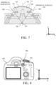
- FIG. 7 is a sectional view of the input apparatus 700.
- the input apparatus 700 includes the same elements as those of the input apparatus 200 except for a keytop 701.
- a knurled portion of a contacted portion 711 of the keytop 701 includes a knurled portion 703 on the -X side and a knurled portion 704 on the +X side with respect to a central axis 702 as a boundary.
- the vertices of the twill shape are located on a spherical surface 705 with a center 707 and a radius SR2.
- the vertices of the twill shape are located on a spherical surface 706 with a center 708 and a radius SR3.
- the center 707 is positioned on the central axis 702 and the center 708 is positioned on the -X side of the central axis 702.
- This variation improves the ease of the tilt operation by the thus configured spherical surfaces, but can acquire similar effects by changing the size of the radius SR depending on the area. That is, the vertices of the twill shape may be located on a plurality of spherical surfaces having different radii.
- the configuration according to this variation can provide the input apparatus 700 with improved operability of both the tilt operation and the press operation.
- FIG. 8 is a rear view of camera 800 according to the second embodiment.
- the camera 800 includes an input apparatus 900 configured to receive input through press and tilt operations.
- a dial 902 is disposed around the input apparatus 900.
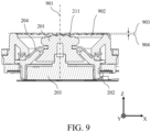
- FIG. 9 is a sectional view of the input apparatus 900. Since the configuration of the input apparatus 900 is similar to that of the input apparatus 200 in the first embodiment, those elements, which are corresponding elements in the first embodiment, will be designated by the same reference numerals. A difference between this embodiment and the first embodiment is a rotationally operable dial (rotating input apparatus) 902 disposed around the input apparatus 900 with a rotation center coaxial with an operation axis 901 for the tilt operation and press operation of the input apparatus 900. That is, the dial 902 is rotatable around the operation axis 901 for the tilt operation and press operation in the input apparatus 900. As illustrated in FIG.
- the operation surface 903 of the dial 902 is higher than a height 904 of the vertex of the contacted portion 211 of the input apparatus 900.
- the height 904 of the vertex of the contacted portion 211 can be made lower than the conventional height or the operation surface 903 of the dial 902. Therefore, as described above, the height of the operation surface 903 of the dial 902 can be higher than the height 904 of the vertex of the contacted portion 211, and the contacted portion 211 of the input apparatus 900 does not hinder the rotational operation of the dial 902.
- the configuration according to this embodiment can provide the input apparatus 900 with improved operability of both the tilt operation and the press operation even in a case where the rotationally operable member is disposed around the input apparatus 900.
- An input apparatus includes an operation surface having a twill shape and configured to receive input through tilt operation and press operation, and a wall portion formed at an end of the operation surface.
- Each vertex of the twill shape is located on a spherical surface.
- the wall portion protrudes from the spherical surface.
Landscapes
- Engineering & Computer Science (AREA)
- General Engineering & Computer Science (AREA)
- Theoretical Computer Science (AREA)
- Human Computer Interaction (AREA)
- Physics & Mathematics (AREA)
- General Physics & Mathematics (AREA)
- Multimedia (AREA)
- Signal Processing (AREA)
- Switches With Compound Operations (AREA)
- Mechanical Control Devices (AREA)
- Position Input By Displaying (AREA)
- Camera Bodies And Camera Details Or Accessories (AREA)
Abstract
Description
- One of the aspects of the embodiments relates generally to an input apparatus for information input, and more particularly to an input apparatus for input through tilt operation.
- An electronic apparatus is demanded for a wide variety of operation members. For example,
Japanese Patent Laid-Open No. 2002-236548 - However, the input apparatus disclosed in
Japanese Patent Laid-Open No. 2002-236548 - Some input apparatuses configured to receive input through the multidirectional tilt operations and installed in electronic apparatuses such as conventional cameras have a concave or convex portion on a flat operation surface that the finger of the user touches. However, these shaped input apparatuses have difficulty in the press operation and may hurt the user in the continuous press operation.
- The present invention in its first aspect provides an input apparatus as specified in claims 1 to 5.
- The present invention in its second aspect provides claims 6 to 9.
- Further features of the disclosure will become apparent from the following description of embodiments with reference to the attached drawings.
-
-
FIG. 1 is a rear view of a camera according to a first embodiment. -
FIG. 2 is a sectional view of an input apparatus according to the first embodiment. -
FIG. 3 illustrates the input apparatus during tilt operation according to the first embodiment. -
FIG. 4 is a perspective view of a contacted portion of a keytop according to the first embodiment. -
FIG. 5 is an enlarged sectional view of the contacted portion according to the first embodiment. -
FIG. 6 illustrates how the user holds a camera according to a variation of the first embodiment. -
FIG. 7 is a sectional view of an input apparatus according to the variation. -
FIG. 8 is a rear view of a camera according to a second embodiment. -
FIG. 9 is a sectional view of the input apparatus according to the second embodiment. - Referring now to the accompanying drawings, a detailed description will be given of embodiments according to the disclosure. Corresponding elements in respective figures will be designated by the same reference numerals, and a duplicate description thereof will be omitted.
- Referring now to
FIGs. 1 to 5 , a description will be given of an electronic apparatus according to a first embodiment. The electronic apparatus according to this embodiment includes, for example, a digital camera. The electronic apparatus will be referred to ascamera 100 hereinafter. -
FIG. 1 is a rear view of thecamera 100 according to this embodiment. Thecamera 100 has agrip portion 101 to be gripped by the right hand of a user. Thecamera 100 includes aninput apparatus 200 at a position where the user can operate it with his thumb in a case where the user holds thecamera 100 via thegrip portion 101, and theinput apparatus 200 is configured to receive input through press operation in a pressing direction and tilt operation in multiple directions. Coordinate axes illustrated inFIG. 1 are provided to define directions in the description, and are also used in other figures. An X-axis is set to a horizontal direction of thecamera 100, a Y-axis is set to a vertical direction, and a Z-axis is set to a depth direction. -
FIG. 2 is a sectional view of theinput apparatus 200.FIG. 3 illustrates theinput apparatus 200 during tilt operation. Theinput apparatus 200 includes akeytop 201, amovable switch 203 mounted on a printedwiring board 202, a drip-proof member 204, and asupport member 205. Thekeytop 201 is engaged with theshaft portion 203a of themovable switch 203. The user can tilt or press down thekeytop 201 by pressing his finger against a contactedportion 211 of thekeytop 201. Thereby, the user can input information to themovable switch 203 by tilting in eight directions and pressing down in the axial direction (-Z direction in each figure). As illustrated inFIG. 3 , the tilt operation of theinput apparatus 200 is performed by tilting thekeytop 201 by an angle α relative to each of the eight directions. This operation inputs operation information in the tilt direction into themovable switch 203. The drip-proof member 204 is engaged with and held in aconcave portion 201a provided in part of thekeytop 201. In a case where thekeytop 201 is moved, the drip-proof member 204 moves together with theconcave portion 201a to maintain its engagement with theconcave portion 201a. The drip-proof member 204 is sandwiched and fixed between thesupport member 205 and anexterior cover member 206. Thereby, water and dust can be prevented from entering thecamera 100. -
FIG. 4 is a perspective view of the contactedportion 211 of thekeytop 201. The contactedportion 211 mainly includes a knurled portion (operation surface) 301 having a twill shape, that the finger pad of the user touches, and awall portion 302 for preventing the finger of the user from slipping during tilt operation. -
FIG. 5 is an enlarged sectional view of the contactedportion 211. The contacted portion 211 (the outer shape of the knurled portion 301) has a circular outer shape, and the contacted portion 211 (the knurled portion 301) has a diameter ϕ. Each vertex of the twill shape of theknurled portion 301 is on a spherical surface (P surface inFIG. 5 ) having a radius SR. Thewall portion 302 formed at the end of theknurled portion 301 protrudes from the P surface by a height H. In this embodiment, thewall portion 302 is provided continuously along the outer circumference of the circularknurled portion 301, but this embodiment is not limited to this example. Thewall portion 302 may be provided discontinuously along the outer circumference of the circularknurled portion 301. That is, a plurality of arcuate wall portions may be provided along the outer circumference of theknurled portion 301. Since theknurled portion 301 is a spherical surface, the axis of the press operation direction can be easily recognized, and the operability of the press operation is improved. Since theknurled portion 301 is a spherical surface, the user can easily place his finger on the tilt operation, and the operability of the tilt operation is improved. Since theknurled portion 301 has a twill shape, the frictional force with the finger is improved during tilt operation, and the operability of tilt operation is improved. - The radius SR of the spherical surface and the diameter ϕ of the contacted
portion 211 may satisfy the following inequality (1):
- In a case where the radius SR becomes smaller than 0.8ϕ and the user presses down the
keytop 201, the pressure applied to the finger becomes biased toward the center of thecontacted portion 211, causing pain in the finger if the press operation continues. On the other hand, in a case where the radius SR becomes larger than 1.2ϕ and the user presses down thekeytop 201, the pressure applied to the finger becomes dispersed around the contactedportion 211, and the certainty of the press operation decreases. Therefore, the contactedportion 211 according to this embodiment may have a shape that satisfies inequality (1). - A convex angle of the twill shape of the knurled portion 301 (angle between the normal to the P surface and the convex slope of the twill shape) is θ. The convex angle θ and the operation angle α during the tilt operation illustrated in
FIG. 3 satisfy the following inequality (2).
- In a case where the angle θ becomes lower than 45° and the finger of the user touches the
keytop 201, the pressure received from each vertex of the twill shape increases, causing pain in the finger. In a case where θ is higher than 90°-2α and the finger of the user touches thekeytop 201, the finger continuously touches the twill shape and easily slips. Therefore, the contactedportion 211 according to this embodiment may have a shape that satisfies the inequality (2). - The contacted
portion 211 of thekeytop 201 according to this embodiment may be disposed closest to the user (+Z direction) in an area where the thumb of the user is projected. This is because the accessibility of the thumb decreases as the contactedportion 211 of thekeytop 201 is positioned in the -Z direction. However, this condition is not essential. - The above configuration can provide the
input apparatus 200 capable of improving the operability of both tilt operation and press operation. - Referring now to
FIGs. 6 and7 , a description of an electronic apparatus according to a variation of the first embodiment. Similarly to the first embodiment, the electronic apparatus according to this variation is a digital camera as an example. The electronic apparatus will be referred to as acamera 600 hereinafter.FIG. 6 illustrates thecamera 600 held by the user. Thecamera 600 includes aninput apparatus 700 configured to receive input through the press and tilt operations. As illustrated inFIG. 6 , the user tilts theinput apparatus 700 with his right thumb. In the tilt operation, the ease of operation differs depending on the direction. The operation in the direction of approaching the grip (operation in the +X direction in the figure) is easy to apply force, the operability improves. The operation in the direction away from the grip (operation in the -X direction inFIG. 6 ) is difficult. -
FIG. 7 is a sectional view of theinput apparatus 700. Theinput apparatus 700 includes the same elements as those of theinput apparatus 200 except for akeytop 701. A knurled portion of a contactedportion 711 of thekeytop 701 includes aknurled portion 703 on the -X side and aknurled portion 704 on the +X side with respect to acentral axis 702 as a boundary. In theknurled portion 703, the vertices of the twill shape are located on aspherical surface 705 with acenter 707 and a radius SR2. In theknurled portion 704, the vertices of the twill shape are located on aspherical surface 706 with acenter 708 and a radius SR3. Thecenter 707 is positioned on thecentral axis 702 and thecenter 708 is positioned on the -X side of thecentral axis 702. Thus, the user can easily perform the tilt operation even in a moving direction away from the grip. - In this variation, the vertices of the twill shape are located on a plurality of spherical surfaces having different centers. More specifically, the size of the radius SR remains unchanged (SR2=SR3), and the center position of the spherical surface is shifted. This variation improves the ease of the tilt operation by the thus configured spherical surfaces, but can acquire similar effects by changing the size of the radius SR depending on the area. That is, the vertices of the twill shape may be located on a plurality of spherical surfaces having different radii.
- The configuration according to this variation can provide the
input apparatus 700 with improved operability of both the tilt operation and the press operation. - Referring now to
FIGs. 8 and9 , a description will be given of an electronic apparatus according to a second embodiment. The electronic apparatus according to this embodiment is, for example, a digital camera. The electronic apparatus will be referred to as acamera 800 hereinafter.FIG. 8 is a rear view ofcamera 800 according to the second embodiment. Thecamera 800 includes aninput apparatus 900 configured to receive input through press and tilt operations. Adial 902 is disposed around theinput apparatus 900. -
FIG. 9 is a sectional view of theinput apparatus 900. Since the configuration of theinput apparatus 900 is similar to that of theinput apparatus 200 in the first embodiment, those elements, which are corresponding elements in the first embodiment, will be designated by the same reference numerals. A difference between this embodiment and the first embodiment is a rotationally operable dial (rotating input apparatus) 902 disposed around theinput apparatus 900 with a rotation center coaxial with anoperation axis 901 for the tilt operation and press operation of theinput apparatus 900. That is, thedial 902 is rotatable around theoperation axis 901 for the tilt operation and press operation in theinput apparatus 900. As illustrated inFIG. 9 , theoperation surface 903 of thedial 902 is higher than aheight 904 of the vertex of the contactedportion 211 of theinput apparatus 900. This is because the contactedportion 211 according to this embodiment is less slippery relative to the keytop of the conventional input apparatus and the press operation is easier. Theheight 904 of the vertex of the contactedportion 211 can be made lower than the conventional height or theoperation surface 903 of thedial 902. Therefore, as described above, the height of theoperation surface 903 of thedial 902 can be higher than theheight 904 of the vertex of the contactedportion 211, and the contactedportion 211 of theinput apparatus 900 does not hinder the rotational operation of thedial 902. - The configuration according to this embodiment can provide the
input apparatus 900 with improved operability of both the tilt operation and the press operation even in a case where the rotationally operable member is disposed around theinput apparatus 900. - While the disclosure has been described with reference to embodiments, it is to be understood that the disclosure is not limited to the disclosed embodiments. The scope of the following claims is to be accorded the broadest interpretation so as to encompass all such modifications and equivalent structures and functions.
- An input apparatus includes an operation surface having a twill shape and configured to receive input through tilt operation and press operation, and a wall portion formed at an end of the operation surface. Each vertex of the twill shape is located on a spherical surface. The wall portion protrudes from the spherical surface.
Claims (9)
- An input apparatus (200, 700, 900) comprising:an operation surface (301) having a twill shape and configured to receive input through tilt operation and press operation; anda wall portion (302) formed at an end of the operation surface,characterized in that each vertex of the twill shape is located on a spherical surface (P surface),wherein the wall portion protrudes from the spherical surface.
- The input apparatus according to claim 1, characterized in that the operation surface has a circular outer shape, wherein the following inequality is satisfied:

- The input apparatus according to claim 1 or 2, characterized in that the following inequality is satisfied:

- The input apparatus according to any one of claims 1 to 3, characterized in that the spherical surface includes a plurality of spherical surfaces with different centers.
- The input apparatus according to claim 4, characterized in that the spherical surface includes a plurality of spherical surfaces with different radii
- An electronic apparatus (100, 600, 800) comprising:a grip portion (101) to be gripped by a user; andthe input apparatus (200, 700, 900) according to any one of claims 1 to 5 so that the user gripping the grip portion can operate the input apparatus with a finger of the user.
- The electronic apparatus according to claim 6, further comprising a rotational input apparatus (902) that is rotationally operable and disposed around the input apparatus.
- The electronic apparatus according to claim 7, characterized in that the rotational input apparatus is a dial (902) rotatable around an operation axis (901) of the tilt operation and the press operation in the input apparatus.
- The electronic apparatus according to claim 7, characterized in that the operation surface of the rotational input apparatus is higher than the vertex of the operation surface in the input apparatus.
Applications Claiming Priority (1)
| Application Number | Priority Date | Filing Date | Title |
|---|---|---|---|
| JP2022123744A JP2024021132A (en) | 2022-08-03 | 2022-08-03 | Input devices and electronic equipment |
Publications (1)
| Publication Number | Publication Date |
|---|---|
| EP4318174A1 true EP4318174A1 (en) | 2024-02-07 |
Family
ID=86942912
Family Applications (1)
| Application Number | Title | Priority Date | Filing Date |
|---|---|---|---|
| EP23180894.0A Pending EP4318174A1 (en) | 2022-08-03 | 2023-06-22 | Input apparatus and electronic apparatus |
Country Status (3)
| Country | Link |
|---|---|
| US (1) | US12608092B2 (en) |
| EP (1) | EP4318174A1 (en) |
| JP (1) | JP2024021132A (en) |
Citations (9)
| Publication number | Priority date | Publication date | Assignee | Title |
|---|---|---|---|---|
| JPS6013622Y2 (en) * | 1982-10-19 | 1985-05-01 | 株式会社太洋工作所 | injection mold |
| US5432530A (en) * | 1991-05-15 | 1995-07-11 | Fujitsu Limited | Pointing device and method of control of same |
| JPH0828216A (en) * | 1994-07-14 | 1996-01-30 | Jidosha Buhin Kogyo Kk | Roller supporting structure of roller type rocker arm |
| EP0960685B1 (en) * | 1995-10-05 | 2002-01-09 | Minnesota Mining And Manufacturing Company | Method for knurling a workpiece |
| JP2002236548A (en) | 2001-02-09 | 2002-08-23 | Alps Electric Co Ltd | Coordinate input device and keyboard input device, and electronic equipment |
| US6831629B2 (en) * | 2001-01-19 | 2004-12-14 | Nagano Fujitsu Component Limited | Pointing device |
| US20100124634A1 (en) * | 1996-09-26 | 2010-05-20 | Slotta Mark R | Cushioned cap with annular portion and method for forming same |
| US20130100016A1 (en) * | 2011-10-20 | 2013-04-25 | Alps Electric Co., Ltd. | Input device |
| US20210250471A1 (en) * | 2020-02-07 | 2021-08-12 | Canon Kabushiki Kaisha | Information input device and image capturing device of the same |
Family Cites Families (9)
| Publication number | Priority date | Publication date | Assignee | Title |
|---|---|---|---|---|
| TW353171B (en) * | 1995-05-10 | 1999-02-21 | Nintendo Co Ltd | Manipulator provided with an analog joy stick |
| DE602004010763T2 (en) * | 2003-10-14 | 2008-04-30 | Alps Electric Co., Ltd. | Joystick Input Device |
| US20050269769A1 (en) * | 2004-06-07 | 2005-12-08 | Herschel Naghi | Handheld controller |
| US20120039579A1 (en) * | 2010-08-12 | 2012-02-16 | Play Pusher, Inc. | Multi-angle audio and video production system and method |
| CN114930483B (en) * | 2020-01-10 | 2025-06-17 | 阿尔卑斯阿尔派株式会社 | Multi-directional input device |
| US20220305373A1 (en) * | 2021-03-25 | 2022-09-29 | Microsoft Technology Licensing, Llc | Sound reducing directional input stick |
| JP7781550B2 (en) * | 2021-07-05 | 2025-12-08 | キヤノン株式会社 | electronic equipment |
| EP4365715B1 (en) * | 2021-09-24 | 2026-02-25 | Nintendo Co., Ltd. | Directional input device and controller |
| JP7694909B2 (en) * | 2021-11-17 | 2025-06-18 | アルプスアルパイン株式会社 | Composite Input Device |
-
2022
- 2022-08-03 JP JP2022123744A patent/JP2024021132A/en active Pending
-
2023
- 2023-06-22 EP EP23180894.0A patent/EP4318174A1/en active Pending
- 2023-07-26 US US18/359,484 patent/US12608092B2/en active Active
Patent Citations (9)
| Publication number | Priority date | Publication date | Assignee | Title |
|---|---|---|---|---|
| JPS6013622Y2 (en) * | 1982-10-19 | 1985-05-01 | 株式会社太洋工作所 | injection mold |
| US5432530A (en) * | 1991-05-15 | 1995-07-11 | Fujitsu Limited | Pointing device and method of control of same |
| JPH0828216A (en) * | 1994-07-14 | 1996-01-30 | Jidosha Buhin Kogyo Kk | Roller supporting structure of roller type rocker arm |
| EP0960685B1 (en) * | 1995-10-05 | 2002-01-09 | Minnesota Mining And Manufacturing Company | Method for knurling a workpiece |
| US20100124634A1 (en) * | 1996-09-26 | 2010-05-20 | Slotta Mark R | Cushioned cap with annular portion and method for forming same |
| US6831629B2 (en) * | 2001-01-19 | 2004-12-14 | Nagano Fujitsu Component Limited | Pointing device |
| JP2002236548A (en) | 2001-02-09 | 2002-08-23 | Alps Electric Co Ltd | Coordinate input device and keyboard input device, and electronic equipment |
| US20130100016A1 (en) * | 2011-10-20 | 2013-04-25 | Alps Electric Co., Ltd. | Input device |
| US20210250471A1 (en) * | 2020-02-07 | 2021-08-12 | Canon Kabushiki Kaisha | Information input device and image capturing device of the same |
Also Published As
| Publication number | Publication date |
|---|---|
| US20240045513A1 (en) | 2024-02-08 |
| US12608092B2 (en) | 2026-04-21 |
| JP2024021132A (en) | 2024-02-16 |
Similar Documents
| Publication | Publication Date | Title |
|---|---|---|
| US12357907B2 (en) | Input device | |
| JP2019061038A (en) | Imaging apparatus | |
| JPH10214128A (en) | Joystick type multi-function controller | |
| US20050113144A1 (en) | Pivotal display for a mobile communications device | |
| CN115022441B (en) | Electronic equipment | |
| EP3133628B1 (en) | Input apparatus | |
| KR20070039133A (en) | Computer input device | |
| US20240167621A1 (en) | Head mounted device | |
| EP4318174A1 (en) | Input apparatus and electronic apparatus | |
| JPH0937358A (en) | Keyboard and video camera control system | |
| US20060175154A1 (en) | Torque adjusting mechanism | |
| JP2011023313A (en) | Electronic equipment | |
| JP7624534B2 (en) | Input device, game controller, information processing device | |
| JPH0973365A (en) | Pen mouse | |
| TWI915212B (en) | Electronic operation system, bracelet mouse, and detection machine of bracelet mouse | |
| CN112242264B (en) | Electronic Devices | |
| JP4784468B2 (en) | Operating device | |
| JPH08278434A (en) | Lens barrel | |
| WO2024161461A1 (en) | Controller | |
| JP2006318687A (en) | Directional input device | |
| CN116583811A (en) | operating device | |
| JP2024176795A (en) | Ring-shaped device | |
| JP6652817B2 (en) | Operation input device | |
| JP2024176778A (en) | Ring-shaped device | |
| JP2024176818A (en) | Ring-shaped device |
Legal Events
| Date | Code | Title | Description |
|---|---|---|---|
| PUAI | Public reference made under article 153(3) epc to a published international application that has entered the european phase |
Free format text: ORIGINAL CODE: 0009012 |
|
| STAA | Information on the status of an ep patent application or granted ep patent |
Free format text: STATUS: THE APPLICATION HAS BEEN PUBLISHED |
|
| AK | Designated contracting states |
Kind code of ref document: A1 Designated state(s): AL AT BE BG CH CY CZ DE DK EE ES FI FR GB GR HR HU IE IS IT LI LT LU LV MC ME MK MT NL NO PL PT RO RS SE SI SK SM TR |
|
| STAA | Information on the status of an ep patent application or granted ep patent |
Free format text: STATUS: REQUEST FOR EXAMINATION WAS MADE |
|
| 17P | Request for examination filed |
Effective date: 20240807 |
|
| RBV | Designated contracting states (corrected) |
Designated state(s): AL AT BE BG CH CY CZ DE DK EE ES FI FR GB GR HR HU IE IS IT LI LT LU LV MC ME MK MT NL NO PL PT RO RS SE SI SK SM TR |
|
| STAA | Information on the status of an ep patent application or granted ep patent |
Free format text: STATUS: EXAMINATION IS IN PROGRESS |
|
| 17Q | First examination report despatched |
Effective date: 20251031 |