EP4318154A1 - Diagnostic device and diagnostic method - Google Patents
Diagnostic device and diagnostic method Download PDFInfo
- Publication number
- EP4318154A1 EP4318154A1 EP21933003.2A EP21933003A EP4318154A1 EP 4318154 A1 EP4318154 A1 EP 4318154A1 EP 21933003 A EP21933003 A EP 21933003A EP 4318154 A1 EP4318154 A1 EP 4318154A1
- Authority
- EP
- European Patent Office
- Prior art keywords
- value
- diagnosis
- status
- normalization
- limit value
- Prior art date
- Legal status (The legal status is an assumption and is not a legal conclusion. Google has not performed a legal analysis and makes no representation as to the accuracy of the status listed.)
- Withdrawn
Links
Images







Classifications
-
- F—MECHANICAL ENGINEERING; LIGHTING; HEATING; WEAPONS; BLASTING
- F24—HEATING; RANGES; VENTILATING
- F24F—AIR-CONDITIONING; AIR-HUMIDIFICATION; VENTILATION; USE OF AIR CURRENTS FOR SCREENING
- F24F11/00—Control or safety arrangements
- F24F11/30—Control or safety arrangements for purposes related to the operation of the system, e.g. for safety or monitoring
- F24F11/32—Responding to malfunctions or emergencies
- F24F11/38—Failure diagnosis
-
- F—MECHANICAL ENGINEERING; LIGHTING; HEATING; WEAPONS; BLASTING
- F24—HEATING; RANGES; VENTILATING
- F24F—AIR-CONDITIONING; AIR-HUMIDIFICATION; VENTILATION; USE OF AIR CURRENTS FOR SCREENING
- F24F11/00—Control or safety arrangements
- F24F11/50—Control or safety arrangements characterised by user interfaces or communication
- F24F11/52—Indication arrangements, e.g. displays
-
- G—PHYSICS
- G05—CONTROLLING; REGULATING
- G05B—CONTROL OR REGULATING SYSTEMS IN GENERAL; FUNCTIONAL ELEMENTS OF SUCH SYSTEMS; MONITORING OR TESTING ARRANGEMENTS FOR SUCH SYSTEMS OR ELEMENTS
- G05B23/00—Testing or monitoring of control systems or parts thereof
- G05B23/02—Electric testing or monitoring
- G05B23/0205—Electric testing or monitoring by means of a monitoring system capable of detecting and responding to faults
- G05B23/0218—Electric testing or monitoring by means of a monitoring system capable of detecting and responding to faults characterised by the fault detection method dealing with either existing or incipient faults
- G05B23/0221—Preprocessing measurements, e.g. data collection rate adjustment; Standardization of measurements; Time series or signal analysis, e.g. frequency analysis or wavelets; Trustworthiness of measurements; Indexes therefor; Measurements using easily measured parameters to estimate parameters difficult to measure; Virtual sensor creation; De-noising; Sensor fusion; Unconventional preprocessing inherently present in specific fault detection methods like PCA-based methods
-
- F—MECHANICAL ENGINEERING; LIGHTING; HEATING; WEAPONS; BLASTING
- F24—HEATING; RANGES; VENTILATING
- F24F—AIR-CONDITIONING; AIR-HUMIDIFICATION; VENTILATION; USE OF AIR CURRENTS FOR SCREENING
- F24F2130/00—Control inputs relating to environmental factors not covered by group F24F2110/00
Definitions
- the present disclosure relates to a technique to diagnose an operational status of a device.
- Patent Literature 1 There is a technique described in Patent Literature 1, as a technique to diagnose an operational status of a device.
- the technique of Patent Literature 1 regards a predetermined period after an air conditioner is installed, as a period during which the air conditioner is normal, and stores a set of status values during the period, as a normal operational status.
- a status value is a value relating to a status of the air conditioner, and is, for example, a value indicated by a sensor that detects the status of the air conditioner, or a value that sets control details for the air conditioner.
- Patent Literature 1 compares the set of status values of the air conditioner acquired for diagnosis with the normal operational status. Then, the technique of Patent Literature 1 performs, for example, an F test or a t test, and determines that the air conditioner is abnormal when there is a significant difference between the two.
- Patent Literature 1 JP 4281334 B2
- Patent Literature 1 can detect that the device is abnormal. However, according to the technique of Patent Literature 1, when it is detected that the device is abnormal, operation of the device needs to stop for repair or the like of the device. Further, since the device is already abnormal, it may take a long time for the repair or the like.
- the fact that the operational status of the device is changing needs to be detected at a stage before the device results in an abnormality, that is, a transitional stage (an intermediate stage between normal and abnormal) during which a transition is made from normal to abnormal. Then, when the operational status of the device is changing, it is desirable to perform appropriate maintenance and to avoid the device from stopping the operation.
- a transitional stage an intermediate stage between normal and abnormal
- Patent Literature 1 has a problem of being unable to detect a change in the operational status of the device at the stage before the device results in the abnormality.
- One of main purposes of the present disclosure is to solve a problem such as above. More specifically, the present disclosure mainly aims to detect a change in an operational status of a device at a stage before the device results in an abnormality.
- a diagnosis apparatus includes:
- normalization makes it possible to detect a change in an operational status of a device at a stage before the device results in an abnormality.
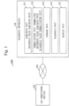
- Fig. 1 illustrate a configuration example of a diagnosis system 1000 according to the present embodiment.
- the diagnosis system 1000 is configured with a diagnosis apparatus 100 and an air conditioner 200.
- the diagnosis apparatus 100 and the air conditioner 200 are connected by a network 300.
- the network 300 may be a wired network or a wireless network.
- a plurality of types of sensors are arranged in the air conditioner 200.
- the status value is a value indicating an operational status of the air conditioner 200.
- the operational status of the air conditioner 200 is, for example, a refrigerant status, a load status, or the like.
- the status value is a concept that includes a reference value and a diagnosis value to be described below. That is, the status value measured during a normal estimation period to be described below is the reference value, and the status value measured during a diagnosis period to be described below is the diagnosis value.
- the air conditioner 200 transmits to the diagnosis apparatus 100, a plurality of types of status values measured by the plurality of types of sensors.
- Pd a discharge pressure-of-refrigerant
- Ps a suction pressure-of-refrigerant
- Td a discharge temperature-of-refrigerant
- Ts a suction temperature-of-refrigerant
- Tl an outlet liquid temperature-of-condenser
- Ti an intake air temperature-of-evaporator
- f a frequency-of-compressor
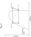
- Pd, Ps, Td, Ts, and Tl are basic physical quantities that constitute a p-h diagram ( Fig. 9 ) which is often used for representing a refrigerant status. Further, To, Ti, and f (correspond to load) are physical quantities representing an environmental condition.
- the present embodiment will be described under an assumption that the air conditioner 200 collectively transmits to the diagnosis apparatus 100, the plurality of types of status values measured by the plurality of types of sensors. However, each sensor may individually transmit the status value to the diagnosis apparatus 100.
- the air conditioner 200 is an example of a device.
- the diagnosis apparatus 100 acquires the plurality of types of status values from the air conditioner 200, and normalizes each of the acquired plurality of types of status values. Then, the diagnosis apparatus 100 diagnoses the operational status of the air conditioner 200, using the normalized plurality of types of status values.
- To acquire the plurality of types of status values from the air conditioner 200 includes a case where the diagnosis apparatus 100 acquires the status value from each sensor.
- the diagnosis apparatus 100 includes an acquiring unit 101, a normalization unit 102, a storage unit 103, a diagnosis unit 104, and a display unit 105, as functional configurations.
- the acquiring unit 101 Details of the acquiring unit 101, the normalization unit 102, the storage unit 103, the diagnosis unit 104, and the display unit 105 will be described below.
- An operational procedure of the diagnosis apparatus 100 is equivalent to a diagnosis method.
- Fig. 2 illustrates a hardware configuration example of the diagnosis apparatus 100 illustrated in Fig. 1 .
- the diagnosis apparatus 100 is a computer.
- the diagnosis apparatus 100 includes a processor 901, a main storage device 902, an auxiliary storage device 903, a communication device 904, and an input/output device 905, as pieces of hardware.
- the auxiliary storage device 903 stores programs that implement functions of the acquiring unit 101, the normalization unit 102, the diagnosis unit 104, and the display unit 105 illustrated in Fig. 1 .
- These programs are loaded from the auxiliary storage device 903 into the main storage device 902. Then, the processor 901 executes these programs and performs operation of the acquiring unit 101, the normalization unit 102, the diagnosis unit 104, and the display unit 105 to be described below.
- Fig. 3 schematically illustrates a state in which the processor 901 executes the programs that implement the functions of the acquiring unit 101, the normalization unit 102, the diagnosis unit 104, and the display unit 105.
- the normalization unit 102 illustrated in Fig. 1 is implemented by the main storage device 902 or the auxiliary storage device 903.
- the communication device 904 communicates with the air conditioner 200 via the network 300.
- the input/output device 905 is, for example, a keyboard, a mouse, or a display device.
- the acquiring unit 101 acquires (receives) the plurality of types of status values, using the communication device 904.
- the acquiring unit 101 acquires as a plurality of types of reference values, the plurality of types of status values of the air conditioner 200, during the normal estimation period.
- the normal estimation period is a period during which the air conditioner 200 is estimated to operate normally.
- the acquiring unit 101 acquires from the air conditioner 200 as a plurality of types of diagnosis values, the plurality of types of status values, during the diagnosis period.
- the diagnosis period is a period during which it is not clear whether or not the air conditioner 200 operates normally and which is after the normal estimation period.
- the acquiring unit 101 is equivalent to a diagnosis value acquiring unit.
- the normalization unit 102 normalizes the plurality of types of reference values acquired during the normal estimation period, according to a predetermined normalization rule.
- a value obtained from the normalization of the reference value is referred to as a normalized reference value.
- the normalization unit 102 normalizes the plurality of types of diagnosis values acquired during the diagnosis period, according to the normalization rule.
- a value obtained from the normalization of the diagnosis value is referred to as a normalized diagnosis value.
- the normalization unit 102 is equivalent to a normalized reference value acquiring unit and a diagnosis value normalization unit.
- the storage unit 103 stores a plurality of types of normalized reference values and a plurality of types of normalized diagnosis values.
- the storage unit 103 stores the normalization rule.
- the diagnosis unit 104 diagnoses the operational status of the air conditioner 200 during the diagnosis period, using the normalized reference values and the normalized diagnosis values.
- the display unit 105 displays on a display device, a diagnosis result notification message indicating a diagnosis result of the diagnosis unit 104.
- Fig. 3 illustrate an operational example of the diagnosis apparatus 100 during the normal estimation period according to the present embodiment.
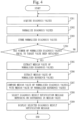
- Fig. 4 illustrates an operational example of the diagnosis apparatus 100 during the diagnosis period according to the present embodiment.
- the flow of Fig. 3 is repeated at a predetermined execution cycle.
- the execution cycle is, for example, one minute.
- the acquiring unit 101 acquires (receives) from the air conditioner 200, the plurality of types of status values as the reference values, within the normal estimation period (step S101).
- the acquiring unit 101 outputs the acquired reference values to the normalization unit 102.
- the air conditioner 200 is in a transitional status immediately after startup and/or when a load changes, since a refrigerant status and/or an actuator status significantly fluctuates. It is desirable to avoid the normal estimation period from including a period of the transitional status such as above. That is, it is desirable that the normal estimation period is only a stable period during which the air conditioner 200 is stable. The stable period can be determined based on, for example, an elapsed time from the startup of the air conditioner 200 or a time during which the actuator status continuously remains unchanged.
- step S101 the acquiring unit 101 acquires as the reference values, Pd, Ps, Td, Ts, T, To, Ti, and f.
- Pd will be mainly described for simplifying the description. The following description is applied also to the status values other than Pd.
- the normalization unit 102 normalizes each of the reference values acquired in step S101 according to the normalization rule (step S102).
- the reference value normalized by the normalization unit 102 is the normalized reference value.
- the normalization unit 102 stores the normalized reference values obtained in step S102 into the storage unit 103 (step S103).
- step S104 the acquiring unit 101 determines whether or not the normal estimation period has ended.
- step S101 is performed again in a next execution cycle (for example, after one minute has elapsed).
- the normal estimation period is, for example, one month from installation of the air conditioner 200.
- the normal estimation period may be any period during which the air conditioner 200 is estimated to operate normally.
- the operational flow of Fig. 4 begins with start of the diagnosis period.
- the diagnosis period is designated by, for example, a user of the diagnosis apparatus 100 via the input/output device 905.
- the acquiring unit 101 acquires (receives) from the air conditioner 200, the plurality of types of status values as the diagnosis values (step S201).
- the acquiring unit 101 outputs the acquired diagnosis values to the normalization unit 102.
- the normalization unit 102 normalizes each of the diagnosis values acquired in step S201 according to the normalization rule (step S202).
- the diagnosis value normalized by the normalization unit 102 is the normalized diagnosis value.
- the normalization unit 102 stores the normalized diagnosis values obtained in step S202 into the storage unit 103 (step S203).
- the normalization unit 102 determines whether or not the number of normalized diagnosis values equal to a target number has been obtained (step S204).
- step S205 When the number of normalized diagnosis values equal to the target number has been obtained, the process proceeds to step S205.
- step S201 is performed again in a next execution cycle (for example, after one minute has elapsed).
- the target number can be arbitrarily decided by the user of the diagnosis apparatus 100.
- the diagnosis unit 104 extracts a median value of the normalized diagnosis values (step S205).
- the diagnosis unit 104 reads from the storage unit 103, the number of normalized diagnosis values equal to the target value for the status value Pd. Then, the diagnosis unit 104 extracts the median value of the read number of normalized diagnosis values equal to the target number for the status value Pd. The diagnosis unit 104 performs the same operation for the other status values.
- the diagnosis unit 104 extracts a median value of the normalized reference values (step S206).
- the diagnosis unit 104 reads from the storage unit 103, the plurality of normalized reference values for the status value Pd. Then, the diagnosis unit 104 extracts the median value of the read plurality of normalized reference values for the status value Pd. The diagnosis unit 104 performs the same operation for the other status values.
- the diagnosis unit 104 compares the median value of the normalized diagnosis values extracted in step S205 with the median value of the normalized reference values extracted in step S206 (step S207).
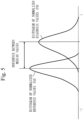
- the diagnosis unit 104 may generate a histogram of the normalized diagnosis values for the status value Pd and a histogram of the normalized reference values for the status value Pd, and compare median values of the histograms with each other.
- diagnosis unit 104 may compare the normalized diagnosis values with the normalized reference values, using a method other than the comparison of the median values.
- the diagnosis unit 104 selects the diagnosis result notification message depending on a difference in the median value obtained from the comparison in step S207 (step S208).
- diagnosis result notification messages are prepared depending on a level of the difference in the median value.
- the diagnosis unit 104 selects the diagnosis result notification message corresponding to the level of the difference in the median value obtained from the comparison in step S207.
- diagnosis unit 104 displays on, for example, a display device, the diagnosis result notification message selected in step S208, via the display unit 105 (step S209).
- step S102 a procedure of the normalization by the normalization unit 102 performed in step S102 and step S202 will be described.
- step S102 the procedure of the normalization in step S102 will be described with reference to Figs. 7 and 8 .
- Fig. 7 it is assumed that the execution cycle is one minute. 1 min in the column of "execution cycle” means the first cycle of the execution cycle. Further, 2 min means the second cycle of the execution cycle. Although only up to 2 min is indicated in Fig. 7 , it is assumed that there are also items of the execution cycles after 3 min.
- reference values obtained during each execution cycle is indicated in the column of "reference values".
- a subscript of the reference value corresponds to the number of times of execution cycles.
- an "upper limit value-of-reference value”, a “lower limit value-of-reference value”, and a “normalized reference value” for each execution cycle are indicated in the column of "Pd". Although only the column of "Pd” is indicated in Fig. 7 for the depiction convenience, there are the “upper limit value-of-reference value”, the “lower limit value-of-reference value”, and the “normalized reference value” similarly also for the other reference values such as Ps.
- the "upper limit value-of-reference value” is an upper limit value possible for the reference value Pd during each execution cycle.
- the upper limit value-of-reference value of the reference value Pd is written as Pdmax.
- the subscript of Pdmax corresponds to the number of times of execution cycles.
- the "lower limit value-of-reference value” is a lower limit value possible for the reference value Pd during each execution cycle.
- the lower limit value-of-reference value of the reference value Pd is written as Pdmin.
- the subscript of Pdmin corresponds to the number of times of execution cycles.
- the normalization unit 102 acquires the upper limit value-of-reference value Pdmax and the lower limit value-of-reference value Pdmin at a time point when the reference value Pd is acquired from the air conditioner 200.
- the normalization rule is a rule that defines to decide, based on a ratio of a difference between a status value (Pd n ) of n (n ⁇ 1) th cycle of the execution cycle and an upper limit value-of-status value (Pdmax n ) to a difference between the status value (Pd n ) and a lower limit value-of-status value (Pdmin n ), a position of the status value (Pd n ) within a normalization range (a range from "1" to "-1" in the example of Fig. 7 ) which is a numerical value range from a predetermined upper limit value to a predetermined lower limit value, and to normalize the status value (Pd n ).
- the normalization unit 102 acquires as an upper limit value-of-reference value Pdmax 1 and a lower limit value-of-reference value Pdmin 1 , an upper limit value and a lower limit value possible for the reference value Pd 1 at a time point when the reference value Pd 1 of the first cycle of the execution cycle is acquired.
- the normalization unit 102 decides a position of the reference value Pd 1 within the numerical value range (the normalization range) between "1" and "-1” and normalizes the reference value Pd 1 , based on a ratio of a difference between the reference value Pd 1 and the upper limit value-of-reference value Pdmax 1 to a difference between the reference value Pd 1 and the lower limit value-of-reference value Pdmin 1 .
- the normalized reference value of the reference value Pd 1 is written as "Pdi*".
- the normalized reference value of a reference value Pd 2 is written as "Pd 2 *".
- the normalized reference value Pd 1 * is a numerical value within the numerical value range (the normalization range) between "1" and "-1" (the normalized reference value Pd 1 * is "0.4" in the example of Fig. 7 ).
- the normalization unit 102 normalizes the reference value Pd 1 , using equations (1), (2), and (3) indicated in Fig. 8 .
- Fig. 7 describes the procedure of the normalization by the normalization unit 102, and the normalization unit 102 does not need to use the table illustrated in Fig. 7 for the normalization.
- step S202 is also performed according to the procedure indicated in Figs. 7 and 8 .
- the normalization unit 102 acquires as an upper limit value-of-diagnosis value Pdmax i and a lower limit value-of-diagnosis value Pdmin i , an upper limit value and a lower limit value possible for the diagnosis value Pd i at a time point when the diagnosis value Pd i of i (i ⁇ 1) th cycle of the execution cycle is acquired during the diagnosis period.
- the normalization unit 102 decides a position of the diagnosis value Pd i within the numerical value range (the normalization range) between "1" and "-1” and normalizes the diagnosis value Pd i , based on a ratio of a difference between the diagnosis value Pd i and the upper limit value-of-diagnosis value Pdmax i to a difference between the diagnosis value Pd i and the lower limit value-of-diagnosis value Pdmin i .
- diagnosis value Pd i is within a range between the upper limit value-of-diagnosis value Pdmax i and the lower limit value-of-diagnosis value Pdmin i
- the normalized diagnosis value Pd i is a numerical value within the numerical value range (the normalization range) between "1" and "-1".
- Pdmax is an upper limit value of the discharge pressure Pd within a range in which the air conditioner 200 does not abnormally stop. In order to prevent damage due to an excessive increase in the discharge pressure Pd, the air conditioner 200 normally forcibly stops operation when the discharge pressure Pd exceeds a predetermined value. Pdmax is the predetermined value functioning in this way.
- Pdmax is normally described in specifications, a service manual, or the like of the air conditioner 200, as an explanation of the abnormal stop. Therefore, for example, the user of the diagnosis apparatus 100 sets Pdmax in advance in the normalization unit 102.
- Pdmin is a lower limit value of the discharge pressure Pd within the range in which the air conditioner 200 does not abnormally stop.
- Psmax is an upper limit value of the suction pressure Ps within a range in which the air conditioner 200 does not abnormally stop.
- the normalization unit 102 acquires as Psmax, a saturation pressure conversion value of the intake air temperature-of-evaporator Ti. This is because an evaporation temperature is lower than the intake air temperature-of-evaporator Ti.
- Psmin is a lower limit value of the suction pressure Ps within the range in which the air conditioner 200 does not abnormally stop.
- the air conditioner 200 In order to prevent damage due to an excessive decrease in the suction pressure Ps, the air conditioner 200 normally forcibly stops the operation when the suction pressure Ps falls below a predetermined value.
- Psmin is the predetermined value mentioned above.
- Psmin is normally described in the specifications, the service manual, or the like of the air conditioner 200, as an explanation of the abnormal stop. Therefore, for example, the user of the diagnosis apparatus 100 sets Psmin in advance in the normalization unit 102.
- an upper limit value-of-status value Tdmax and a lower limit value-of-status value Tdmin of the discharge temperature-of-refrigerant Td an upper limit value-of-status value Tsmax and a lower limit value-of-status value Tsmin of the suction temperature-of-refrigerant Ts, and an upper limit value-of-status value Tlmax and a lower limit value-of-status value Tlmin of the intake air temperature-of-condenser T 1 , will be described.
- Tdmax is an upper limit value of the discharge temperature Td within a range in which the air conditioner 200 does not abnormally stop. In order to prevent damage due to an excessive increase in the discharge temperature Td, the air conditioner 200 normally forcibly stops the operation when the discharge temperature Td exceeds a predetermined value. Tdmax is the predetermined value functioning in this way.
- Tdmax is normally described in the specifications, the service manual, or the like of the air conditioner 200, as an explanation of the abnormal stop. Therefore, for example, the user of the diagnosis apparatus 100 sets Tdmax in advance in the normalization unit 102.
- Tdmin is a lower limit value of the discharge temperature Td within the range in which the air conditioner 200 does not abnormally stop.
- the normalization unit 102 acquires the condensation temperature as Tdmin. This is because the air conditioner 200 normally has a discharge overheat degree > 0.
- the condensation temperature is a value obtained from conversion of the discharge pressure Pd into a saturation temperature.
- Tsmax is an upper limit value of the suction temperature-of-refrigerant Ts within a range in which the air conditioner 200 does not abnormally stop.
- Tsmin is a lower limit value of the suction temperature-of-refrigerant Ts within the range in which the air conditioner 200 does not abnormally stop.
- the normalization unit 102 acquires the evaporation temperature as Tsmin. This is because the air conditioner 200 normally has a suction overheat degree > 0.
- the evaporation temperature is a value obtained from conversion of the suction pressure Ps into a saturation temperature.
- Tlmax is an upper limit value of the outlet liquid temperature-of-condenser Tl within a range in which the air conditioner 200 does not abnormally stop.
- the normalization unit 102 acquires the condensation temperature as Tlmax. This is because the air conditioner 200 normally has a supercooling degree > 0.
- the condensation temperature is a value obtained from convention of the discharge pressure Pd into a saturation temperature.
- Tlmin is a lower limit value of the outlet liquid temperature-of-condenser Tl within the range in which the air conditioner 200 does not abnormally stop.
- the normalization unit 102 acquires the intake air temperature-of-condenser To as Tlmin. This is because the outlet liquid temperature-of-condenser Tl is higher than the intake air temperature-of-condenser To.
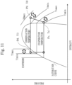
- Tdmax, Tdmin, Tsmax, Tsmin, Tlmax, and Tlmin are added on the p-h diagram illustrated in Fig. 9 .
- the diagnosis apparatus 100 compares the normalized diagnosis values with the normalized reference values. That is, by normalizing the reference values and the diagnosis values, the diagnosis apparatus 100 is able to diagnose the operational status of the air conditioner 200 even if an environmental condition changes between a time of initial installation and a time of diagnosis of the air conditioner 200. Therefore, according to the present embodiment, it is possible to diagnose whether the air conditioner 200 is approaching abnormality or there is no change in the operational status of the air conditioner 200. That is, according to the present embodiment, it is possible to detect the change in the operational status of the air conditioner 200 in a transitional stage before the air conditioner 200 results in an abnormality.
- a service person of the air conditioner 200 can take a measure for preventing the abnormality, such as a field survey. As a result, it is possible to continue the operation of the air conditioner 200.
- the description has proceeded using the air conditioner 200 as an example of the device.
- the device is not limited to the air conditioner 200. This embodiment can be applied also to any device as long as the device may change its operational status as time elapses.
- the normalization unit 102 normalizes the reference values to obtain the normalized reference values.
- an external device normalizes the reference values, and the normalization unit 102 may acquire the normalized reference values from the external device.
- diagnosis accuracy is improved by performing diagnosis in consideration of an operational environment of the air conditioner 200 at a time when a diagnosis value is measured.
- Embodiment 1 differences from Embodiment 1 will be mainly described.
- the configuration of the diagnosis system 1000 according to the present embodiment is as illustrated in Fig. 1 .
- the hardware configuration example of the diagnosis apparatus 100 according to the present embodiment is as illustrated in Fig. 2 .
- Fig. 12 illustrates an operational example of the diagnosis apparatus 100 during the normal estimation period according to the present embodiment.
- Fig. 13 illustrates an operational example of the diagnosis apparatus 100 during the diagnosis period according to the present embodiment.
- the acquiring unit 101 acquires (receives) from the air conditioner 200, reference values and operational environment information, during the normal estimation period (step S111).
- the operational environment information is information indicating an operational environment of the air conditioner 200 at a time point when a reference value is measured.
- the operational environment is, for example, an outdoor air temperature, an indoor air temperature, or the like.
- the acquiring unit 101 may acquire any status value as the operational environment information.
- the acquiring unit 101 may acquire as the operational environment information, for example, the frequency-of-compressor f.
- the acquiring unit 101 outputs to the normalization unit 102, the acquired reference values and the acquired operational environment information.
- Step S102 the normalization unit 102 normalizes each of the reference values acquired in step S101 according to the normalization rule (step S102).
- Step S102 is the same as that illustrated in Fig. 3 .
- the normalization unit 102 associates the normalized reference values and the operational environment information with each other, and stores them into the storage unit 103 (step S113).
- Step S104 is the same as that illustrated in Fig. 3 .
- the acquiring unit 101 receives (acquires) from the air conditioner 200, diagnosis values and the operational environment information (step S211).
- the operational environment information acquired in step S211 is also information indicating an operational environment of the air conditioner 200 at a time point when a diagnosis value is measured.
- Step S202 the normalization unit 102 normalizes each of the diagnosis values acquired in step S201 according to the normalization rule (step S202).
- Step S202 is the same as that illustrated in Fig. 4 .
- the normalization unit 102 associates the normalized diagnosis values and the operational environment information with each other, and stores them into the storage unit 103 (step S213).
- Step S204 the normalization unit 102 determines whether or not the number of normalized diagnosis values equal to a target number has been obtained (step S204). Step S204 is the same as that illustrated in Fig. 4 .
- Step S205 is the same as that illustrated in Fig. 4 .
- the diagnosis unit 104 extracts a median value of the normalized reference values whose operational environment is common to that of the normalized diagnosis values (step S216). "Operational environment is common" means that the operational environment is the same as or similar to another.
- the diagnosis unit 104 identifies the operational environment indicated in the operational environment information that is associated with the normalized diagnosis values from which the median value has been extracted in step S205. Then, the diagnosis unit 104 reads from the storage unit 103, a plurality of normalized reference values associated with the operational environment information indicating the operational environment that is the same as or similar to the identified operational environment. Then, the diagnosis unit 104 extracts a median value among the read plurality of normalized reference values.
- Step S207 is the same as that illustrated in Fig. 4 .
- Step S208 is the same as that illustrated in Fig. 4 .
- diagnosis unit 104 displays on, for example, a display device, via the display unit 105, the diagnosis result notification message selected in step S208 (step S209).
- Step S209 is the same as that illustrated in Fig. 4 .
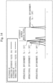
- Fig. 14 illustrates an example of steps S216 and S207 in Fig. 13 .
- the diagnosis unit 104 extracts a median value among the read plurality of normalized reference values (step S216).
- the diagnosis apparatus 100 selects the normalized reference value whose operational environment is the same as or similar to the operational environment of the normalized diagnosis value. Therefore, according to the present embodiment, the diagnosis apparatus 100 is possible to perform diagnosis, using the normalized reference value whose operational environment is close to that of the normalized diagnosis value. As a result, it is possible to improve diagnosis accuracy.
- installation conditions normally differ for each air conditioner 200.
- the installation conditions are such as the length of a refrigerant pipe, an amount of additional refrigerant filled, and an air flow status around a suction port. If the installation conditions differ, operational statuses differ for each air conditioner 200 even if outdoor air temperatures, indoor air temperatures, loads, and the like are the same.
- the normalization unit 102 corrects the reference value or the upper limit value-of-reference value and the lower limit value-of-reference value according to a correction rule. Further, in the present embodiment, the normalization unit 102 corrects the diagnosis value or the upper limit value-of-diagnosis value and the lower limit value-of-diagnosis value according to the correction rule. For example, the normalization unit 102 performs correction based on a standard status value, an upper limit value-of-standard status value and a lower limit value-of-standard status value.
- the standard status value, the upper limit value-of-standard status value and the lower limit value-of-standard status value are hereinafter referred to as a standard status value, a standard upper limit value and a standard lower limit value, respectively. Further, the standard status value, the standard upper limit value and the standard lower limit value are correctively referred to as a standard value.
- the standard value is, for example, a value such as a value measured at a time of factory shipment, a value indicated in catalog specifications or a service handbook, or the like.
- Embodiment 1 differences from Embodiment 1 will be mainly described.
- Fig. 15 illustrates a configuration example of the diagnosis system 1000 according to the present embodiment.
- a database 106 is added, compared with Fig. 1 .
- the database 106 stores standard status values, standard upper limit values and standard lower limit values.
- the database 106 is implemented by the main storage device 902 or the auxiliary storage device 903.
- the normalization unit 102 corrects the reference value or the upper limit value-of-reference value and the lower limit value-of-reference value according to the correction rule, using the standard value. Then, the normalization unit 102 performs normalization, using the corrected reference value or the corrected upper limit value-of-reference value and the corrected lower limit value-of-reference value, and obtains the normalized reference value.
- the normalization unit 102 corrects the diagnosis value or the upper limit value-of-diagnosis value and the lower limit value-of-diagnosis value according to the correction rule, using the standard value. Then, the normalization unit 102 performs normalization, using the corrected diagnosis value or the corrected upper limit value-of-diagnosis value and the corrected lower limit value-of-diagnosis value, and obtains the normalized diagnosis value.
- the storage unit 103 also stores the correction rule in addition to the normalization rule.
- a hardware configuration example of the diagnosis apparatus 100 according to the present embodiment is as illustrated in Fig. 2 .
- step S102 the normalization unit 102 normalizes each reference value according to the normalization rule.
- the status value or the upper limit value-of-status value and the lower limit value-of-status value is/are corrected according to the correction rule.
- the normalization unit 102 corrects in step S102, the reference value or the upper limit value-of-reference value and the lower limit value-of-reference value, using the standard value. Then, the normalization unit 102 performs normalization, using the corrected reference value or the corrected upper limit value-of-reference value and the corrected lower limit value-of-reference value, and obtains the normalized reference value.
- step S102 Since the processes other than step S102 are the same as those described in Embodiment 1, the description thereof is omitted.
- the operation of the diagnosis apparatus 100 according to the present embodiment during the diagnosis period is as illustrated in Fig. 4 .
- step S202 the normalization unit 102 normalizes each diagnosis value according to the normalization rule.
- the normalization rule it is described in the normalization rule that the status value is corrected according to the correction rule.
- the normalization unit 102 corrects in step S202, the diagnosis value, using the standard value. Then, the normalization unit 102 performs normalization, using the corrected diagnosis value, and obtains the normalized diagnosis value.
- step S202 Since the processes other than step S202 are the same as those illustrated in Embodiment 1, the description thereof is omitted.
- Fig. 16 illustrates a procedure for the correction in steps S102 and S202.
- Fig. 16 illustrates an example of the correction for the status value Pd 1 .
- the normalization unit 102 corrects the reference value Pdi in step S102
- the normalization unit 102 is able to correct the diagnosis value Pd i in step S202 by the same procedure as described below.
- the reference value Pd 1 before correction is a value close to the upper limit value-of-reference value Pdmax 1 .
- the standard status value Pd is positioned approximately midway between the standard lower limit value Pdmin and the standard upper limit value Pdmax.
- the normalization unit 102 calculates the corrected reference value Pd 1 # according to an equation (1).
- a midpoint m 1 included in the equation (1) is calculated, using an equation (2), and the midpoint m is calculated, using an equation (3).
- the corrected reference value Pd 1 # is located approximately midway between the lower limit value-of-reference value Pdmin 1 and the upper limit value-of-reference value Pdmax 1 , as illustrated in "after correction" in Fig. 16 .
- the diagnosis apparatus 100 corrects the reference value and also corrects the diagnosis value, depending on the installation conditions. Therefore, according to the present embodiment, it is possible to absorb differences in the installation conditions and it is possible to improve diagnosis accuracy.
- Embodiments 1 and 3 have been described above and two or more of these embodiments may be implemented in combination.
- one of these embodiments may be partially implemented.
- two or more of these embodiments may be partially implemented in combination.
- the processor 901 illustrated in Fig. 2 is an Integrated Circuit (IC) that performs processing.
- IC Integrated Circuit
- the processor 901 is a Central Processing Unit (CPU), a Digital Signal Processor (DSP), or the like.
- the main storage device 902 illustrated in Fig. 2 is a Random Access Memory (RAM).
- RAM Random Access Memory
- the auxiliary storage device 903 illustrated in Fig. 2 is a Read Only Memory (ROM), a flash memory, a Hard Disk Drive (HDD), or the like.
- ROM Read Only Memory
- HDD Hard Disk Drive
- the communication device 904 illustrated in Fig. 2 is an electronic circuit that executes a communication process for data.
- the communication device 904 is, for example, a communication chip or a Network Interface Card (NIC).
- NIC Network Interface Card
- the input/output device 905 is, for example, a mouse, a keyboard, or a display device.
- auxiliary storage device 903 also stores an Operating System (OS).
- OS Operating System
- the processor 901 While executing at least the part of the OS, the processor 901 executes programs that implement functions of the acquiring unit 101, the normalization unit 102, the diagnosis unit 104, and the display unit 105.
- processor 901 By the processor 901 executing the OS, task management, memory management, file management, communication control, and the like are performed.
- At least one of information, data, a signal value, and a variable value that indicate results of processes of the acquiring unit 101, the normalization unit 102, the diagnosis unit 104, and the display unit 105 is stored in at least one of the main storage device 902, the auxiliary storage device 903, and a register and a cache memory in the processor 901.
- the programs that implement the functions of the acquiring unit 101, the normalization unit 102, the diagnosis unit 104, and the display unit 105 may be stored in a portable recording medium such as a magnetic disk, a flexible disk, an optical disc, a compact disc, a Blu-ray (registered trademark) disc, or a DVD. Then, the portable recording medium storing the programs that implement the functions of the acquiring unit 101, the normalization unit 102, the diagnosis unit 104, and the display unit 105 may be distributed.
- a portable recording medium such as a magnetic disk, a flexible disk, an optical disc, a compact disc, a Blu-ray (registered trademark) disc, or a DVD.
- each of the acquiring unit 101, the normalization unit 102, the diagnosis unit 104, and the display unit 105 may be read as a “circuit", “step”, “procedure”, “process”, or “circuitry”.
- the diagnosis apparatus 100 may be implemented by a processing circuit.
- the processing circuit is, for example, a logic Integrated Circuit (IC), a Gate Array (GA), an Application Specific Integrated Circuit (ASIC), or a Field-Programmable Gate Array (FPGA).
- each of the acquiring unit 101, the normalization unit 102, the diagnosis unit 104, and the display unit 105 is implemented as a part of the processing circuit.
- processing circuitry a superordinate concept of the processor and the processing circuit.
- each of the processor and the processing circuit is a specific example of the "processing circuitry”.
- 100 diagnosis apparatus; 101: acquiring unit; 102: normalization unit; 103: storage unit; 104: diagnosis unit; 105: display unit; 106: database; 200: air conditioner; 300: network; 901: processor; 902: main storage device; 903: auxiliary storage device; 904: communication device; 905: input/output device; 1000: diagnosis system
Landscapes
- Engineering & Computer Science (AREA)
- General Engineering & Computer Science (AREA)
- Chemical & Material Sciences (AREA)
- Combustion & Propulsion (AREA)
- Mechanical Engineering (AREA)
- Biomedical Technology (AREA)
- Health & Medical Sciences (AREA)
- Human Computer Interaction (AREA)
- Physics & Mathematics (AREA)
- General Physics & Mathematics (AREA)
- Automation & Control Theory (AREA)
- Air Conditioning Control Device (AREA)
- Testing Of Devices, Machine Parts, Or Other Structures Thereof (AREA)
- Testing And Monitoring For Control Systems (AREA)
Abstract
Description
- The present disclosure relates to a technique to diagnose an operational status of a device.
- There is a technique described in
Patent Literature 1, as a technique to diagnose an operational status of a device. The technique ofPatent Literature 1 regards a predetermined period after an air conditioner is installed, as a period during which the air conditioner is normal, and stores a set of status values during the period, as a normal operational status. A status value is a value relating to a status of the air conditioner, and is, for example, a value indicated by a sensor that detects the status of the air conditioner, or a value that sets control details for the air conditioner. - Then, the technique of
Patent Literature 1 compares the set of status values of the air conditioner acquired for diagnosis with the normal operational status. Then, the technique ofPatent Literature 1 performs, for example, an F test or a t test, and determines that the air conditioner is abnormal when there is a significant difference between the two. - Patent Literature 1:
JP 4281334 B2 - The technique of
Patent Literature 1 can detect that the device is abnormal. However, according to the technique ofPatent Literature 1, when it is detected that the device is abnormal, operation of the device needs to stop for repair or the like of the device. Further, since the device is already abnormal, it may take a long time for the repair or the like. - In order to continue to provide a user of the device with safety, security, comfort, convenience, and the like, the fact that the operational status of the device is changing needs to be detected at a stage before the device results in an abnormality, that is, a transitional stage (an intermediate stage between normal and abnormal) during which a transition is made from normal to abnormal. Then, when the operational status of the device is changing, it is desirable to perform appropriate maintenance and to avoid the device from stopping the operation.
- The technique of
Patent Literature 1 has a problem of being unable to detect a change in the operational status of the device at the stage before the device results in the abnormality. - One of main purposes of the present disclosure is to solve a problem such as above. More specifically, the present disclosure mainly aims to detect a change in an operational status of a device at a stage before the device results in an abnormality.
- A diagnosis apparatus according to the present disclosure includes:
- a normalized reference value acquiring unit to acquire a normalized reference value being a value obtained from normalization of a reference value according to a predetermined normalization rule, the reference value being a status value acquired from a device during a normal estimation period during which the device is estimated to operate normally, the status value indicating an operational status of the device;
- a diagnosis value acquiring unit to acquire from the device, the status value as a diagnosis value during a diagnosis period during which it is not clear whether or not the device operates normally and which is after the normal estimation period;
- a diagnosis value normalization unit to normalize the diagnosis value according to the normalization rule; and
- a diagnosis unit to diagnose the operational status of the device during the diagnosis period, using the normalized reference value and a normalized diagnosis value obtained from the normalization of the diagnosis value by the diagnosis value normalization unit.
- According to the present disclosure, normalization makes it possible to detect a change in an operational status of a device at a stage before the device results in an abnormality.
-
-
Fig. 1 is a diagram illustrating a configuration example of a diagnosis system according toEmbodiment 1. -
Fig. 2 is a diagram illustrating a hardware configuration example of a diagnosis apparatus according toEmbodiment 1. -
Fig. 3 is a flowchart illustrating an operational example of the diagnosis apparatus during a normal estimation period according toEmbodiment 1. -
Fig. 4 is a flowchart illustrating an operational example of the diagnosis apparatus during a diagnosis period according toEmbodiment 1. -
Fig. 5 is a diagram illustrating an example of a histogram of normalized reference values (Pd) and an example of a histogram of normalized diagnosis values (Pd) according toEmbodiment 1. -
Fig. 6 is a diagram illustrating examples of diagnosis result notification messages according toEmbodiment 1. -
Fig. 7 is a diagram describing a procedure of normalization according toEmbodiment 1. -
Fig. 8 is a diagram describing the procedure of the normalization according toEmbodiment 1. -
Fig. 9 is a diagram illustrating an example of a p-h diagram according toEmbodiment 1. -
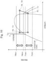
Fig. 10 is a diagram illustrating examples of upper limit value-of-status values and lower limit value-of-status values according toEmbodiment 1. -
Fig. 11 is a diagram illustrating examples of the upper limit value-of-status values and the lower limit value-of-status values according toEmbodiment 1. -
Fig. 12 is a flowchart illustrating an operational example of the diagnosis apparatus during the normal estimation period according toEmbodiment 2. -
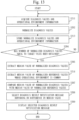
Fig. 13 is a flowchart illustrating an operational example of the diagnosis apparatus during the diagnosis period according toEmbodiment 2. -
Fig. 14 is a diagram illustrating an example of a histogram of normalized reference values (Pd) for each operational environment and an example of a histogram of normalized diagnosis values (Pd) for which the operational environment is set according toEmbodiment 2. -
Fig. 15 is a diagram illustrating a configuration example of the diagnosis system according toEmbodiment 3. -
Fig. 16 is a diagram describing a procedure of correction according toEmbodiment 3. - Embodiments will be described hereinafter with reference to the drawings. In the following description of the embodiments and the drawings, portions denoted by the same reference signs indicate the same or corresponding portions.
-
Fig. 1 illustrate a configuration example of adiagnosis system 1000 according to the present embodiment. - The
diagnosis system 1000 according to the present embodiment is configured with adiagnosis apparatus 100 and anair conditioner 200. Thediagnosis apparatus 100 and theair conditioner 200 are connected by anetwork 300. Thenetwork 300 may be a wired network or a wireless network. - A plurality of types of sensors are arranged in the
air conditioner 200. - Each of the plurality of types of sensors measures a status value. The status value is a value indicating an operational status of the
air conditioner 200. The operational status of theair conditioner 200 is, for example, a refrigerant status, a load status, or the like. - The status value is a concept that includes a reference value and a diagnosis value to be described below. That is, the status value measured during a normal estimation period to be described below is the reference value, and the status value measured during a diagnosis period to be described below is the diagnosis value.
- The
air conditioner 200 transmits to thediagnosis apparatus 100, a plurality of types of status values measured by the plurality of types of sensors. - In the present embodiment, it is assumed that as the status values, for example, Pd: a discharge pressure-of-refrigerant, Ps: a suction pressure-of-refrigerant, Td: a discharge temperature-of-refrigerant, Ts: a suction temperature-of-refrigerant, Tl: an outlet liquid temperature-of-condenser, To: an intake air temperature-of-condenser, Ti: an intake air temperature-of-evaporator, and f: a frequency-of-compressor, are measured.
- Pd, Ps, Td, Ts, and Tl are basic physical quantities that constitute a p-h diagram (
Fig. 9 ) which is often used for representing a refrigerant status. Further, To, Ti, and f (correspond to load) are physical quantities representing an environmental condition. - The present embodiment will be described under an assumption that the
air conditioner 200 collectively transmits to thediagnosis apparatus 100, the plurality of types of status values measured by the plurality of types of sensors. However, each sensor may individually transmit the status value to thediagnosis apparatus 100. - The
air conditioner 200 is an example of a device. - The
diagnosis apparatus 100 acquires the plurality of types of status values from theair conditioner 200, and normalizes each of the acquired plurality of types of status values. Then, thediagnosis apparatus 100 diagnoses the operational status of theair conditioner 200, using the normalized plurality of types of status values. - "To acquire the plurality of types of status values from the
air conditioner 200" includes a case where thediagnosis apparatus 100 acquires the status value from each sensor. - As illustrated in
Fig. 1 , thediagnosis apparatus 100 includes an acquiringunit 101, anormalization unit 102, astorage unit 103, adiagnosis unit 104, and adisplay unit 105, as functional configurations. - Details of the acquiring
unit 101, thenormalization unit 102, thestorage unit 103, thediagnosis unit 104, and thedisplay unit 105 will be described below. - An operational procedure of the
diagnosis apparatus 100 is equivalent to a diagnosis method. -
Fig. 2 illustrates a hardware configuration example of thediagnosis apparatus 100 illustrated inFig. 1 . - The
diagnosis apparatus 100 is a computer. - The
diagnosis apparatus 100 includes aprocessor 901, amain storage device 902, anauxiliary storage device 903, acommunication device 904, and an input/output device 905, as pieces of hardware. - The
auxiliary storage device 903 stores programs that implement functions of the acquiringunit 101, thenormalization unit 102, thediagnosis unit 104, and thedisplay unit 105 illustrated inFig. 1 . - These programs are loaded from the
auxiliary storage device 903 into themain storage device 902. Then, theprocessor 901 executes these programs and performs operation of the acquiringunit 101, thenormalization unit 102, thediagnosis unit 104, and thedisplay unit 105 to be described below. -
Fig. 3 schematically illustrates a state in which theprocessor 901 executes the programs that implement the functions of the acquiringunit 101, thenormalization unit 102, thediagnosis unit 104, and thedisplay unit 105. - The
normalization unit 102 illustrated inFig. 1 is implemented by themain storage device 902 or theauxiliary storage device 903. - The
communication device 904 communicates with theair conditioner 200 via thenetwork 300. - The input/
output device 905 is, for example, a keyboard, a mouse, or a display device. - Next, details of the acquiring
unit 101, thenormalization unit 102, thestorage unit 103, thediagnosis unit 104, and thedisplay unit 105 illustrated inFig. 1 will be described. - The acquiring
unit 101 acquires (receives) the plurality of types of status values, using thecommunication device 904. - More specifically, the acquiring
unit 101 acquires as a plurality of types of reference values, the plurality of types of status values of theair conditioner 200, during the normal estimation period. The normal estimation period is a period during which theair conditioner 200 is estimated to operate normally. - Further, the acquiring
unit 101 acquires from theair conditioner 200 as a plurality of types of diagnosis values, the plurality of types of status values, during the diagnosis period. The diagnosis period is a period during which it is not clear whether or not theair conditioner 200 operates normally and which is after the normal estimation period. - The acquiring
unit 101 is equivalent to a diagnosis value acquiring unit. - The
normalization unit 102 normalizes the plurality of types of reference values acquired during the normal estimation period, according to a predetermined normalization rule. A value obtained from the normalization of the reference value is referred to as a normalized reference value. - Further, the
normalization unit 102 normalizes the plurality of types of diagnosis values acquired during the diagnosis period, according to the normalization rule. A value obtained from the normalization of the diagnosis value is referred to as a normalized diagnosis value. - The
normalization unit 102 is equivalent to a normalized reference value acquiring unit and a diagnosis value normalization unit. - The
storage unit 103 stores a plurality of types of normalized reference values and a plurality of types of normalized diagnosis values. - Further, the
storage unit 103 stores the normalization rule. - The
diagnosis unit 104 diagnoses the operational status of theair conditioner 200 during the diagnosis period, using the normalized reference values and the normalized diagnosis values. - The
display unit 105 displays on a display device, a diagnosis result notification message indicating a diagnosis result of thediagnosis unit 104. -
Fig. 3 illustrate an operational example of thediagnosis apparatus 100 during the normal estimation period according to the present embodiment. -
Fig. 4 illustrates an operational example of thediagnosis apparatus 100 during the diagnosis period according to the present embodiment. - First, the operational example of the
diagnosis apparatus 100 during the normal estimation period will be described with reference toFig. 3 . - The flow of
Fig. 3 is repeated at a predetermined execution cycle. The execution cycle is, for example, one minute. - First, the acquiring
unit 101 acquires (receives) from theair conditioner 200, the plurality of types of status values as the reference values, within the normal estimation period (step S101). The acquiringunit 101 outputs the acquired reference values to thenormalization unit 102. - The
air conditioner 200 is in a transitional status immediately after startup and/or when a load changes, since a refrigerant status and/or an actuator status significantly fluctuates. It is desirable to avoid the normal estimation period from including a period of the transitional status such as above. That is, it is desirable that the normal estimation period is only a stable period during which theair conditioner 200 is stable. The stable period can be determined based on, for example, an elapsed time from the startup of theair conditioner 200 or a time during which the actuator status continuously remains unchanged. - Further, in step S101, as described above, the acquiring
unit 101 acquires as the reference values, Pd, Ps, Td, Ts, T, To, Ti, and f. However, in the following, Pd will be mainly described for simplifying the description. The following description is applied also to the status values other than Pd. - Next, the
normalization unit 102 normalizes each of the reference values acquired in step S101 according to the normalization rule (step S102). - As described above, the reference value normalized by the
normalization unit 102 is the normalized reference value. - Details of the normalization will be described below.
- Next, the
normalization unit 102 stores the normalized reference values obtained in step S102 into the storage unit 103 (step S103). - Next, the acquiring
unit 101 determines whether or not the normal estimation period has ended (step S104). - When the normal estimation period has ended, the flow of
Fig. 3 ends. - On the other hand, when the normal estimation period has not ended, step S101 is performed again in a next execution cycle (for example, after one minute has elapsed).
- The normal estimation period is, for example, one month from installation of the
air conditioner 200. The normal estimation period may be any period during which theair conditioner 200 is estimated to operate normally. - When it is assumed that the execution cycle is one minute and the normal estimation period is thirty days, 43,200 pieces of reference values Pd are obtained (60 (minutes) × 24 (hours) × 30 (days) = 43,200 pieces). Similarly, 43,200 pieces are obtained for each of other reference values.
- Next, the operational example of the
diagnosis apparatus 100 during the diagnosis period will be described with reference toFig. 4 . - The operational flow of
Fig. 4 begins with start of the diagnosis period. The diagnosis period is designated by, for example, a user of thediagnosis apparatus 100 via the input/output device 905. - First, the acquiring
unit 101 acquires (receives) from theair conditioner 200, the plurality of types of status values as the diagnosis values (step S201). The acquiringunit 101 outputs the acquired diagnosis values to thenormalization unit 102. - Next, the
normalization unit 102 normalizes each of the diagnosis values acquired in step S201 according to the normalization rule (step S202). - As described above, the diagnosis value normalized by the
normalization unit 102 is the normalized diagnosis value. - Details of the normalization will be described below.
- Next, the
normalization unit 102 stores the normalized diagnosis values obtained in step S202 into the storage unit 103 (step S203). - Next, the
normalization unit 102 determines whether or not the number of normalized diagnosis values equal to a target number has been obtained (step S204). - When the number of normalized diagnosis values equal to the target number has been obtained, the process proceeds to step S205.
- On the other hand, the number of normalized diagnosis values equal to the target number has not been obtained, step S201 is performed again in a next execution cycle (for example, after one minute has elapsed).
- The target number may be, for example, the number of normalized diagnosis values in one day (60 × 24 = 1,440) or may be the number of normalized diagnosis values in 30 days (60 × 24 × 30 = 43,200). The target number can be arbitrarily decided by the user of the
diagnosis apparatus 100. - When the number of normalized diagnosis values equal to the target number has been obtained (YES in step S204), the
diagnosis unit 104 extracts a median value of the normalized diagnosis values (step S205). - Specifically, the
diagnosis unit 104 reads from thestorage unit 103, the number of normalized diagnosis values equal to the target value for the status value Pd. Then, thediagnosis unit 104 extracts the median value of the read number of normalized diagnosis values equal to the target number for the status value Pd. Thediagnosis unit 104 performs the same operation for the other status values. - Next, the
diagnosis unit 104 extracts a median value of the normalized reference values (step S206). - Specifically, the
diagnosis unit 104 reads from thestorage unit 103, the plurality of normalized reference values for the status value Pd. Then, thediagnosis unit 104 extracts the median value of the read plurality of normalized reference values for the status value Pd. Thediagnosis unit 104 performs the same operation for the other status values. - Next, the
diagnosis unit 104 compares the median value of the normalized diagnosis values extracted in step S205 with the median value of the normalized reference values extracted in step S206 (step S207). - For example, as illustrated in
Fig. 5 , thediagnosis unit 104 may generate a histogram of the normalized diagnosis values for the status value Pd and a histogram of the normalized reference values for the status value Pd, and compare median values of the histograms with each other. - Alternatively, the
diagnosis unit 104 may compare the normalized diagnosis values with the normalized reference values, using a method other than the comparison of the median values. - Next, the
diagnosis unit 104 selects the diagnosis result notification message depending on a difference in the median value obtained from the comparison in step S207 (step S208). - In the present embodiment, as illustrated in
Fig. 6 , it is assumed that the diagnosis result notification messages are prepared depending on a level of the difference in the median value. - The
diagnosis unit 104 selects the diagnosis result notification message corresponding to the level of the difference in the median value obtained from the comparison in step S207. - Finally, the
diagnosis unit 104 displays on, for example, a display device, the diagnosis result notification message selected in step S208, via the display unit 105 (step S209). - Next, a procedure of the normalization by the
normalization unit 102 performed in step S102 and step S202 will be described. - In the following, the procedure of the normalization in step S102 will be described with reference to
Figs. 7 and8 . - In
Fig. 7 , it is assumed that the execution cycle is one minute. 1 min in the column of "execution cycle" means the first cycle of the execution cycle. Further, 2 min means the second cycle of the execution cycle. Although only up to 2 min is indicated inFig. 7 , it is assumed that there are also items of the execution cycles after 3 min. - Further, the reference values obtained during each execution cycle is indicated in the column of "reference values". A subscript of the reference value corresponds to the number of times of execution cycles.
- Further, an "upper limit value-of-reference value", a "lower limit value-of-reference value", and a "normalized reference value" for each execution cycle are indicated in the column of "Pd". Although only the column of "Pd" is indicated in
Fig. 7 for the depiction convenience, there are the "upper limit value-of-reference value", the "lower limit value-of-reference value", and the "normalized reference value" similarly also for the other reference values such as Ps. - The "upper limit value-of-reference value" is an upper limit value possible for the reference value Pd during each execution cycle. The upper limit value-of-reference value of the reference value Pd is written as Pdmax. The subscript of Pdmax corresponds to the number of times of execution cycles.
- The "lower limit value-of-reference value" is a lower limit value possible for the reference value Pd during each execution cycle. The lower limit value-of-reference value of the reference value Pd is written as Pdmin. The subscript of Pdmin corresponds to the number of times of execution cycles.
- In this way, the upper limit value and the lower limit value possible for the reference value Pd vary depending on time points.
- The
normalization unit 102 acquires the upper limit value-of-reference value Pdmax and the lower limit value-of-reference value Pdmin at a time point when the reference value Pd is acquired from theair conditioner 200. - Details of the upper limit value-of-reference value Pdmax and the lower limit value-of-reference value Pdmin will be described below.
- In the present embodiment, the normalization rule is a rule that defines to decide, based on a ratio of a difference between a status value (Pdn) of n (n ≥ 1) th cycle of the execution cycle and an upper limit value-of-status value (Pdmaxn) to a difference between the status value (Pdn) and a lower limit value-of-status value (Pdminn), a position of the status value (Pdn) within a normalization range (a range from "1" to "-1" in the example of
Fig. 7 ) which is a numerical value range from a predetermined upper limit value to a predetermined lower limit value, and to normalize the status value (Pdn). - For example, the
normalization unit 102 acquires as an upper limit value-of-reference value Pdmax1 and a lower limit value-of-reference value Pdmin1, an upper limit value and a lower limit value possible for the reference value Pd1 at a time point when the reference value Pd1 of the first cycle of the execution cycle is acquired. Then, thenormalization unit 102 decides a position of the reference value Pd1 within the numerical value range (the normalization range) between "1" and "-1" and normalizes the reference value Pd1, based on a ratio of a difference between the reference value Pd1 and the upper limit value-of-reference value Pdmax1 to a difference between the reference value Pd1 and the lower limit value-of-reference value Pdmin1. The normalized reference value of the reference value Pd1 is written as "Pdi*". Similarly, the normalized reference value of a reference value Pd2 is written as "Pd2*". - If the reference value Pd1 is within a range between the upper limit value-of-reference value Pdmax1 and the lower limit value-of-reference value Pdmin1, the normalized reference value Pd1* is a numerical value within the numerical value range (the normalization range) between "1" and "-1" (the normalized reference value Pd1* is "0.4" in the example of
Fig. 7 ). - Specifically, the
normalization unit 102 normalizes the reference value Pd1, using equations (1), (2), and (3) indicated inFig. 8 . -
Fig. 7 describes the procedure of the normalization by thenormalization unit 102, and thenormalization unit 102 does not need to use the table illustrated inFig. 7 for the normalization. - The normalization of step S202 is also performed according to the procedure indicated in
Figs. 7 and8 . - That is, based on the normalization rule described above, the
normalization unit 102 acquires as an upper limit value-of-diagnosis value Pdmaxi and a lower limit value-of-diagnosis value Pdmini, an upper limit value and a lower limit value possible for the diagnosis value Pdi at a time point when the diagnosis value Pdi of i (i ≥ 1) th cycle of the execution cycle is acquired during the diagnosis period. Then, thenormalization unit 102 decides a position of the diagnosis value Pdi within the numerical value range (the normalization range) between "1" and "-1" and normalizes the diagnosis value Pdi, based on a ratio of a difference between the diagnosis value Pdi and the upper limit value-of-diagnosis value Pdmaxi to a difference between the diagnosis value Pdi and the lower limit value-of-diagnosis value Pdmini. - If the diagnosis value Pdi is within a range between the upper limit value-of-diagnosis value Pdmaxi and the lower limit value-of-diagnosis value Pdmini, the normalized diagnosis value Pdi is a numerical value within the numerical value range (the normalization range) between "1" and "-1".
- Next, Pdmax, Pdmin, an upper limit value-of-status value Psmax of the suction pressure Ps, and a lower limit value-of-status value Psmin of the suction pressure Ps will be described.
- Pdmax is an upper limit value of the discharge pressure Pd within a range in which the
air conditioner 200 does not abnormally stop. In order to prevent damage due to an excessive increase in the discharge pressure Pd, theair conditioner 200 normally forcibly stops operation when the discharge pressure Pd exceeds a predetermined value. Pdmax is the predetermined value functioning in this way. - Pdmax is normally described in specifications, a service manual, or the like of the
air conditioner 200, as an explanation of the abnormal stop. Therefore, for example, the user of thediagnosis apparatus 100 sets Pdmax in advance in thenormalization unit 102. - Pdmin is a lower limit value of the discharge pressure Pd within the range in which the
air conditioner 200 does not abnormally stop. Specifically, thenormalization unit 102 acquires as Pdmin, a saturation pressure conversion value of the intake air temperature-of-condenser To. This is because a condensation temperature is higher than the intake air temperature-of-condenser To (= an outdoor air temperature). - Further, Psmax is an upper limit value of the suction pressure Ps within a range in which the
air conditioner 200 does not abnormally stop. Specifically, thenormalization unit 102 acquires as Psmax, a saturation pressure conversion value of the intake air temperature-of-evaporator Ti. This is because an evaporation temperature is lower than the intake air temperature-of-evaporator Ti. - Further, Psmin is a lower limit value of the suction pressure Ps within the range in which the
air conditioner 200 does not abnormally stop. In order to prevent damage due to an excessive decrease in the suction pressure Ps, theair conditioner 200 normally forcibly stops the operation when the suction pressure Ps falls below a predetermined value. Psmin is the predetermined value mentioned above. - Psmin is normally described in the specifications, the service manual, or the like of the
air conditioner 200, as an explanation of the abnormal stop. Therefore, for example, the user of thediagnosis apparatus 100 sets Psmin in advance in thenormalization unit 102. - In
Fig. 10 , Pdmax, Pdmin, Psmax, and Psmin are added on the p-h diagram illustrated inFig. 9 . - Next, an upper limit value-of-status value Tdmax and a lower limit value-of-status value Tdmin of the discharge temperature-of-refrigerant Td, an upper limit value-of-status value Tsmax and a lower limit value-of-status value Tsmin of the suction temperature-of-refrigerant Ts, and an upper limit value-of-status value Tlmax and a lower limit value-of-status value Tlmin of the intake air temperature-of-condenser T1, will be described.
- Tdmax is an upper limit value of the discharge temperature Td within a range in which the
air conditioner 200 does not abnormally stop. In order to prevent damage due to an excessive increase in the discharge temperature Td, theair conditioner 200 normally forcibly stops the operation when the discharge temperature Td exceeds a predetermined value. Tdmax is the predetermined value functioning in this way. - Tdmax is normally described in the specifications, the service manual, or the like of the
air conditioner 200, as an explanation of the abnormal stop. Therefore, for example, the user of thediagnosis apparatus 100 sets Tdmax in advance in thenormalization unit 102. - Further, Tdmin is a lower limit value of the discharge temperature Td within the range in which the
air conditioner 200 does not abnormally stop. Specifically, thenormalization unit 102 acquires the condensation temperature as Tdmin. This is because theair conditioner 200 normally has a discharge overheat degree > 0. Here, the condensation temperature is a value obtained from conversion of the discharge pressure Pd into a saturation temperature. - Tsmax is an upper limit value of the suction temperature-of-refrigerant Ts within a range in which the
air conditioner 200 does not abnormally stop. Specifically, thenormalization unit 102 acquires the intake air temperature-of-condenser To (= the outdoor air temperature) as Tsmax. This is because the suction temperature Ts is lower than the intake air temperature-of-condenser To. - Tsmin is a lower limit value of the suction temperature-of-refrigerant Ts within the range in which the
air conditioner 200 does not abnormally stop. Specifically, thenormalization unit 102 acquires the evaporation temperature as Tsmin. This is because theair conditioner 200 normally has a suction overheat degree > 0. Here, the evaporation temperature is a value obtained from conversion of the suction pressure Ps into a saturation temperature. - Tlmax is an upper limit value of the outlet liquid temperature-of-condenser Tl within a range in which the
air conditioner 200 does not abnormally stop. Specifically, thenormalization unit 102 acquires the condensation temperature as Tlmax. This is because theair conditioner 200 normally has a supercooling degree > 0. Here, the condensation temperature is a value obtained from convention of the discharge pressure Pd into a saturation temperature. - Tlmin is a lower limit value of the outlet liquid temperature-of-condenser Tl within the range in which the
air conditioner 200 does not abnormally stop. Specifically, thenormalization unit 102 acquires the intake air temperature-of-condenser To as Tlmin. This is because the outlet liquid temperature-of-condenser Tl is higher than the intake air temperature-of-condenser To. - In
Fig. 11 , Tdmax, Tdmin, Tsmax, Tsmin, Tlmax, and Tlmin are added on the p-h diagram illustrated inFig. 9 . - Thus, in the present embodiment, the
diagnosis apparatus 100 compares the normalized diagnosis values with the normalized reference values. That is, by normalizing the reference values and the diagnosis values, thediagnosis apparatus 100 is able to diagnose the operational status of theair conditioner 200 even if an environmental condition changes between a time of initial installation and a time of diagnosis of theair conditioner 200. Therefore, according to the present embodiment, it is possible to diagnose whether theair conditioner 200 is approaching abnormality or there is no change in the operational status of theair conditioner 200. That is, according to the present embodiment, it is possible to detect the change in the operational status of theair conditioner 200 in a transitional stage before theair conditioner 200 results in an abnormality. - When the
air conditioner 200 is approaching the abnormality, a service person of theair conditioner 200 can take a measure for preventing the abnormality, such as a field survey. As a result, it is possible to continue the operation of theair conditioner 200. - In the present embodiment, the description has proceeded using the
air conditioner 200 as an example of the device. However, the device is not limited to theair conditioner 200. This embodiment can be applied also to any device as long as the device may change its operational status as time elapses. - Further, in the present embodiment, the configuration has been described in which the
normalization unit 102 normalizes the reference values to obtain the normalized reference values. Alternatively, an external device normalizes the reference values, and thenormalization unit 102 may acquire the normalized reference values from the external device. - In the present embodiment, an example will be described in which diagnosis accuracy is improved by performing diagnosis in consideration of an operational environment of the
air conditioner 200 at a time when a diagnosis value is measured. - In the present embodiment, differences from
Embodiment 1 will be mainly described. - Matters not described below are the same as those in
Embodiment 1. - The configuration of the
diagnosis system 1000 according to the present embodiment is as illustrated inFig. 1 . - Further, the hardware configuration example of the
diagnosis apparatus 100 according to the present embodiment is as illustrated inFig. 2 . -
Fig. 12 illustrates an operational example of thediagnosis apparatus 100 during the normal estimation period according to the present embodiment. -
Fig. 13 illustrates an operational example of thediagnosis apparatus 100 during the diagnosis period according to the present embodiment. - First, the operational example of the
diagnosis apparatus 100 during the normal estimation period will be described with reference toFig. 12 . - First, the acquiring
unit 101 acquires (receives) from theair conditioner 200, reference values and operational environment information, during the normal estimation period (step S111). - The operational environment information is information indicating an operational environment of the
air conditioner 200 at a time point when a reference value is measured. The operational environment is, for example, an outdoor air temperature, an indoor air temperature, or the like. Further, the acquiringunit 101 may acquire any status value as the operational environment information. The acquiringunit 101 may acquire as the operational environment information, for example, the frequency-of-compressor f. - The acquiring
unit 101 outputs to thenormalization unit 102, the acquired reference values and the acquired operational environment information. - Next, the
normalization unit 102 normalizes each of the reference values acquired in step S101 according to the normalization rule (step S102). Step S102 is the same as that illustrated inFig. 3 . - Next, the
normalization unit 102 associates the normalized reference values and the operational environment information with each other, and stores them into the storage unit 103 (step S113). - Next, the acquiring
unit 101 determines whether or not the normal estimation period has ended (step S104). Step S104 is the same as that illustrated inFig. 3 . - Next, the operational example of the
diagnosis apparatus 100 during the diagnosis period will be described with reference toFig. 13 . - First, the acquiring
unit 101 receives (acquires) from theair conditioner 200, diagnosis values and the operational environment information (step S211). - Further, as with the operational environment information acquired in step S111, the operational environment information acquired in step S211 is also information indicating an operational environment of the
air conditioner 200 at a time point when a diagnosis value is measured. - Next, the
normalization unit 102 normalizes each of the diagnosis values acquired in step S201 according to the normalization rule (step S202). Step S202 is the same as that illustrated inFig. 4 . - Next, the
normalization unit 102 associates the normalized diagnosis values and the operational environment information with each other, and stores them into the storage unit 103 (step S213). - Next, the
normalization unit 102 determines whether or not the number of normalized diagnosis values equal to a target number has been obtained (step S204). Step S204 is the same as that illustrated inFig. 4 . - When the number of normalized diagnosis values equal to the target number has been obtained (YES in step S204), the
diagnosis unit 104 extracts a median value of the normalized diagnosis values (step S205). Step S205 is the same as that illustrated inFig. 4 . - Next, the
diagnosis unit 104 extracts a median value of the normalized reference values whose operational environment is common to that of the normalized diagnosis values (step S216). "Operational environment is common" means that the operational environment is the same as or similar to another. - Specifically, the
diagnosis unit 104 identifies the operational environment indicated in the operational environment information that is associated with the normalized diagnosis values from which the median value has been extracted in step S205. Then, thediagnosis unit 104 reads from thestorage unit 103, a plurality of normalized reference values associated with the operational environment information indicating the operational environment that is the same as or similar to the identified operational environment. Then, thediagnosis unit 104 extracts a median value among the read plurality of normalized reference values. - Next, the
diagnosis unit 104 compares the median value of the normalized diagnosis values extracted in step S205 with the median value of the normalized reference values extracted in step S216 (step S207). Step S207 is the same as that illustrated inFig. 4 . - Next, the
diagnosis unit 104 selects the diagnosis result notification message corresponding to a difference in the median value obtained from the comparison of the median value of the normalized diagnosis values with the median value of the normalized reference values in step S207 (step S208). Step S208 is the same as that illustrated inFig. 4 . - Finally, the
diagnosis unit 104 displays on, for example, a display device, via thedisplay unit 105, the diagnosis result notification message selected in step S208 (step S209). Step S209 is the same as that illustrated inFig. 4 . -
Fig. 14 illustrates an example of steps S216 and S207 inFig. 13 . - In the example of
Fig. 14 , the operational environment of the normalized diagnosis value of the status value Pd is "To = 26°C". That is, the operational environment indicated in the operational environment information associated with the normalized diagnosis value of the status value Pd is "To = 26°C". To is the intake air temperature-of-condenser (= the outdoor air temperature). - In the example of
Fig. 14 , there are "To = 20°C, "To = 25°C" and "To = 30°C" as operational environments of the normalized reference value of the status value Pd. That is, there are the normalized reference value associated with the operational environment information indicating "To = 20°C" as the operational environment, the normalized reference value associated with the operational environment information indicating "To = 25°C" as the operational environment, and the normalized reference value associated with the operational environment information indicating "To = 30°C" as the operational environment. - The operational environment similar to "To = 26°C" which is the operational environment of the normalized diagnosis value, is "To = 25°C". Therefore, the
diagnosis unit 104 reads from thestorage unit 103, the plurality of normalized reference values associated with the operational environment information indicating "To = 25°C". - Then, the
diagnosis unit 104 extracts a median value among the read plurality of normalized reference values (step S216). - After that, the
diagnosis unit 104 compares a median value of the normalized diagnosis values whose operational environments are "To = 26°C" with the median value of the normalized reference values whose operational environments are "To = 25°C" (step S207). -
Fig. 14 illustrates the example in which thediagnosis unit 104 compares the median value of a histogram of the normalized diagnosis values whose operational environments are "To = 26°C" with the median value of a histogram of the normalized reference values whose operational environments are "To = 25°C". - Thus, in the present embodiment, when there is a plurality of normalized reference values whose operational environments differ from each other, the
diagnosis apparatus 100 selects the normalized reference value whose operational environment is the same as or similar to the operational environment of the normalized diagnosis value. Therefore, according to the present embodiment, thediagnosis apparatus 100 is possible to perform diagnosis, using the normalized reference value whose operational environment is close to that of the normalized diagnosis value. As a result, it is possible to improve diagnosis accuracy. - Even for the same models, installation conditions normally differ for each
air conditioner 200. The installation conditions are such as the length of a refrigerant pipe, an amount of additional refrigerant filled, and an air flow status around a suction port. If the installation conditions differ, operational statuses differ for eachair conditioner 200 even if outdoor air temperatures, indoor air temperatures, loads, and the like are the same. - Therefore, even during the normal estimation period, there is a case where the reference value is close to the upper limit value-of-reference value or the lower limit value-of-reference value depending on the installation conditions. Further, similarly, even if the
air conditioner 200 is normal, there is a case where the diagnosis value is close to the upper limit value-of-diagnosis value or the lower limit value-of-diagnosis value depending on the installation conditions. - In the present embodiment, the
normalization unit 102 corrects the reference value or the upper limit value-of-reference value and the lower limit value-of-reference value according to a correction rule. Further, in the present embodiment, thenormalization unit 102 corrects the diagnosis value or the upper limit value-of-diagnosis value and the lower limit value-of-diagnosis value according to the correction rule. For example, thenormalization unit 102 performs correction based on a standard status value, an upper limit value-of-standard status value and a lower limit value-of-standard status value. - The standard status value, the upper limit value-of-standard status value and the lower limit value-of-standard status value are hereinafter referred to as a standard status value, a standard upper limit value and a standard lower limit value, respectively. Further, the standard status value, the standard upper limit value and the standard lower limit value are correctively referred to as a standard value.
- The standard value is, for example, a value such as a value measured at a time of factory shipment, a value indicated in catalog specifications or a service handbook, or the like.
- In the present embodiment, differences from
Embodiment 1 will be mainly described. - Matters not described below are the same as those in
Embodiment 1. -
Fig. 15 illustrates a configuration example of thediagnosis system 1000 according to the present embodiment. - In
Fig. 15 , adatabase 106 is added, compared withFig. 1 . - The
database 106 stores standard status values, standard upper limit values and standard lower limit values. Thedatabase 106 is implemented by themain storage device 902 or theauxiliary storage device 903. - In the present embodiment, the
normalization unit 102 corrects the reference value or the upper limit value-of-reference value and the lower limit value-of-reference value according to the correction rule, using the standard value. Then, thenormalization unit 102 performs normalization, using the corrected reference value or the corrected upper limit value-of-reference value and the corrected lower limit value-of-reference value, and obtains the normalized reference value. - Further, the
normalization unit 102 corrects the diagnosis value or the upper limit value-of-diagnosis value and the lower limit value-of-diagnosis value according to the correction rule, using the standard value. Then, thenormalization unit 102 performs normalization, using the corrected diagnosis value or the corrected upper limit value-of-diagnosis value and the corrected lower limit value-of-diagnosis value, and obtains the normalized diagnosis value. - Further, in the present embodiment, the
storage unit 103 also stores the correction rule in addition to the normalization rule. - Since the acquiring
unit 101, thediagnosis unit 104, and thedisplay unit 105 illustrated inFig. 15 are the same as those illustrated inFig. 1 , the description thereof is omitted. - A hardware configuration example of the
diagnosis apparatus 100 according to the present embodiment is as illustrated inFig. 2 . - Operation of the
diagnosis apparatus 100 according to the present embodiment during a normal estimation period is as illustrated inFig. 3 . - In step S102, the
normalization unit 102 normalizes each reference value according to the normalization rule. However, in the present embodiment, it is described in the normalization rule that the status value or the upper limit value-of-status value and the lower limit value-of-status value is/are corrected according to the correction rule. - Therefore, in the present embodiment, the
normalization unit 102 corrects in step S102, the reference value or the upper limit value-of-reference value and the lower limit value-of-reference value, using the standard value. Then, thenormalization unit 102 performs normalization, using the corrected reference value or the corrected upper limit value-of-reference value and the corrected lower limit value-of-reference value, and obtains the normalized reference value. - Since the processes other than step S102 are the same as those described in
Embodiment 1, the description thereof is omitted. - The operation of the
diagnosis apparatus 100 according to the present embodiment during the diagnosis period is as illustrated inFig. 4 . - In step S202, the
normalization unit 102 normalizes each diagnosis value according to the normalization rule. However, in the present embodiment, as described above, it is described in the normalization rule that the status value is corrected according to the correction rule. - Therefore, in the present embodiment, the
normalization unit 102 corrects in step S202, the diagnosis value, using the standard value. Then, thenormalization unit 102 performs normalization, using the corrected diagnosis value, and obtains the normalized diagnosis value. - Since the processes other than step S202 are the same as those illustrated in
Embodiment 1, the description thereof is omitted. -
Fig. 16 illustrates a procedure for the correction in steps S102 and S202. -
Fig. 16 illustrates an example of the correction for the status value Pd1. - In the following, the example in which the
normalization unit 102 corrects the reference value Pdi in step S102 will be described, but thenormalization unit 102 is able to correct the diagnosis value Pdi in step S202 by the same procedure as described below. - As illustrated in "before correction" in
Fig. 16 , the reference value Pd1 before correction is a value close to the upper limit value-of-reference value Pdmax1. - On the other hand, as illustrated in "standard value" in
Fig. 16 , the standard status value Pd is positioned approximately midway between the standard lower limit value Pdmin and the standard upper limit value Pdmax. - The
normalization unit 102 calculates the corrected reference value Pd1# according to an equation (1). A midpoint m1 included in the equation (1) is calculated, using an equation (2), and the midpoint m is calculated, using an equation (3). - By the
normalization unit 102 correcting the reference value Pd1, the corrected reference value Pd1# is located approximately midway between the lower limit value-of-reference value Pdmin1 and the upper limit value-of-reference value Pdmax1, as illustrated in "after correction" inFig. 16 . - Thus, in the present embodiment, the
diagnosis apparatus 100 corrects the reference value and also corrects the diagnosis value, depending on the installation conditions. Therefore, according to the present embodiment, it is possible to absorb differences in the installation conditions and it is possible to improve diagnosis accuracy. - Embodiments 1 and 3 have been described above and two or more of these embodiments may be implemented in combination.
- Alternatively, one of these embodiments may be partially implemented.
- Alternatively, two or more of these embodiments may be partially implemented in combination.
- Further, the configurations and procedures described in these embodiments may be modified as necessary.
- Finally, a supplementary description of the hardware configuration of the
diagnosis apparatus 100 will be given. - The
processor 901 illustrated inFig. 2 is an Integrated Circuit (IC) that performs processing. - The
processor 901 is a Central Processing Unit (CPU), a Digital Signal Processor (DSP), or the like. - The
main storage device 902 illustrated inFig. 2 is a Random Access Memory (RAM). - The
auxiliary storage device 903 illustrated inFig. 2 is a Read Only Memory (ROM), a flash memory, a Hard Disk Drive (HDD), or the like. - The
communication device 904 illustrated inFig. 2 is an electronic circuit that executes a communication process for data. - The
communication device 904 is, for example, a communication chip or a Network Interface Card (NIC). - As described above, the input/
output device 905 is, for example, a mouse, a keyboard, or a display device. - Further, the
auxiliary storage device 903 also stores an Operating System (OS). - Then, at least a part of the OS is executed by the
processor 901. - While executing at least the part of the OS, the
processor 901 executes programs that implement functions of the acquiringunit 101, thenormalization unit 102, thediagnosis unit 104, and thedisplay unit 105. - By the
processor 901 executing the OS, task management, memory management, file management, communication control, and the like are performed. - Further, at least one of information, data, a signal value, and a variable value that indicate results of processes of the acquiring
unit 101, thenormalization unit 102, thediagnosis unit 104, and thedisplay unit 105 is stored in at least one of themain storage device 902, theauxiliary storage device 903, and a register and a cache memory in theprocessor 901. - Further, the programs that implement the functions of the acquiring
unit 101, thenormalization unit 102, thediagnosis unit 104, and thedisplay unit 105 may be stored in a portable recording medium such as a magnetic disk, a flexible disk, an optical disc, a compact disc, a Blu-ray (registered trademark) disc, or a DVD. Then, the portable recording medium storing the programs that implement the functions of the acquiringunit 101, thenormalization unit 102, thediagnosis unit 104, and thedisplay unit 105 may be distributed. - Further, the "unit" of each of the acquiring
unit 101, thenormalization unit 102, thediagnosis unit 104, and thedisplay unit 105 may be read as a "circuit", "step", "procedure", "process", or "circuitry". - Further, the
diagnosis apparatus 100 may be implemented by a processing circuit. The processing circuit is, for example, a logic Integrated Circuit (IC), a Gate Array (GA), an Application Specific Integrated Circuit (ASIC), or a Field-Programmable Gate Array (FPGA). - In this case, each of the acquiring
unit 101, thenormalization unit 102, thediagnosis unit 104, and thedisplay unit 105 is implemented as a part of the processing circuit. - In the present description, a superordinate concept of the processor and the processing circuit is referred to as "processing circuitry".
- That is, each of the processor and the processing circuit is a specific example of the "processing circuitry".
- 100: diagnosis apparatus; 101: acquiring unit; 102: normalization unit; 103: storage unit; 104: diagnosis unit; 105: display unit; 106: database; 200: air conditioner; 300: network; 901: processor; 902: main storage device; 903: auxiliary storage device; 904: communication device; 905: input/output device; 1000: diagnosis system
Claims (8)
- A diagnosis apparatus comprising:a normalized reference value acquiring unit to acquire a normalized reference value being a value obtained from normalization of a reference value according to a predetermined normalization rule, the reference value being a status value acquired from a device during a normal estimation period during which the device is estimated to operate normally, the status value indicating an operational status of the device;a diagnosis value acquiring unit to acquire from the device, the status value as a diagnosis value during a diagnosis period during which it is not clear whether or not the device operates normally and which is after the normal estimation period;a diagnosis value normalization unit to normalize the diagnosis value according to the normalization rule; anda diagnosis unit to diagnose the operational status of the device during the diagnosis period, using the normalized reference value and a normalized diagnosis value obtained from the normalization of the diagnosis value by the diagnosis value normalization unit.
- The diagnosis apparatus according to claim 1, whereinthe normalized reference value acquiring unit acquires a plurality of normalized reference values obtained according to the normalization rule from the normalization of a plurality of reference values acquired from the device at a plurality of times within the normal estimation period,the diagnosis value acquiring unit acquires a plurality of diagnosis values from the device at a plurality of times within the diagnosis period,the diagnosis value normalization unit normalizes the plurality of diagnosis values according to the normalization rule, andthe diagnosis unit diagnoses the operational status of the device during the diagnosis period, using the plurality of normalized reference values and a plurality of normalized diagnosis values obtained from the normalization by the diagnosis value normalization unit.
- ] The diagnosis apparatus according to claim 2, wherein
the diagnosis unit compares a median value of the plurality of normalized diagnosis values with a median value of the plurality of normalized reference values, and diagnoses the operational status of the device during the diagnosis period. - The diagnosis apparatus according to claim 3, wherein
the diagnosis unit selects a diagnosis result notification message from among a plurality of diagnosis result notification messages each of which indicates a diagnosis result, depending on a difference between the median value of the plurality of normalized diagnosis values and the median value of the plurality of normalized reference values, and outputs the selected diagnosis result notification message. - The diagnosis apparatus according to claim 2, whereinthe normalized reference value acquiring unit acquires operational environment information indicating an operational environment of the device at a time point when a reference value corresponding to each of the plurality of normalized reference values is acquired from the device,the diagnosis value acquiring unit acquires operational environment information indicating an operational environment of the device at a time point when each of the plurality of diagnosis values is acquired from the device, andthe diagnosis unit diagnoses the operational status of the device during the diagnosis period, using a normalized diagnosis value and a normalized reference value each of whose operational environment information indicates a common operational environment.
- The diagnosis apparatus according to claim 1, whereinthe normalization rule is a rule that defines to acquire an upper limit value-of-status value and a lower limit value-of-status value which are an upper limit value and a lower limit value possible for the status value at a time point when the status value is acquired from the device, to decide a position of the status value within a normalization range which is a numerical value range from a predetermined upper limit value to a predetermined lower limit value, based on a ratio of a difference between the status value and the upper limit value-of-status value to a difference between the status value and the lower limit value-of-status value, and to normalize the status value,the normalized reference value acquiring unit acquires a normalized reference value obtained according to the normalization rule by acquiring an upper limit value-of-reference value and a lower limit value-of-reference value which are an upper limit value and a lower limit value possible for the reference value at a time point when the reference value is acquired from the device, and by deciding a position of the reference value within the normalization range, based on a ratio of a difference between the reference value and the upper limit value-of-reference value to a difference between the reference value and the lower limit value-of-reference value, andthe diagnosis value normalization unit, according to the normalization rule, acquires an upper limit value-of-diagnosis value and a lower limit value-of-diagnosis value which are an upper limit value and a lower limit value possible for the diagnosis value at a time point when the diagnosis value is acquired from the device, decides a position of the diagnosis value within the normalization range, based on a ratio of a difference between the diagnosis value and the upper limit value-of-diagnosis value to a difference between the diagnosis value and the lower limit value-of-diagnosis value, and normalizes the diagnosis value.
- The diagnosis apparatus according to claim 1, whereinthe normalization rule is a rule that defines to acquire an upper limit value-of-status value and a lower limit value-of-status value which are an upper limit value and a lower limit value possible for the status value at a time point when the status value is acquired from the device, to correct the status value according to a predetermined correction rule, to decide a position of the status value within a normalization range which is a numerical value range from a predetermine upper limit value to a predetermined lower limit value, based on a ratio of a difference between the corrected status value and the upper limit value-of-status value to a difference between the corrected status value and the lower limit value-of-status value, and to normalize the status value,the normalized reference value acquiring unit acquires a normalized reference value obtained according to the normalization rule by acquiring an upper limit value-of-reference value and a lower limit value-of-reference value which are an upper limit value and a lower limit value possible for the reference value at a time point when the reference value is acquired from the device, by correcting the reference value according to the correction rule, and by deciding a position of the corrected reference value within the normalization range, based on a ratio of a difference between the corrected reference value and the upper limit value-of-reference value to a difference between the corrected reference value and the lower limit value-of-reference value, andthe diagnosis value normalization unit, according to the normalization rule, acquires an upper limit value-of-diagnosis value and a lower limit value-of-diagnosis value which are an upper limit value and a lower limit value possible for the diagnosis value at a time point when the diagnosis value is acquired from the device, corrects the diagnosis value according to the correction rule, decides a position of the corrected diagnosis value within the normalization range, based on a ratio of a difference between the corrected diagnosis value and the upper limit value-of-diagnosis value to a difference between the corrected diagnosis value and the lower limit value-of-diagnosis value, and normalizes the diagnosis value.
- A diagnosis method comprising:by a computer, acquiring a normalized reference value being a value obtained from normalization of a reference value according to a predetermined normalization rule, the reference value being a status value acquired from a device during a normal estimation period during which the device is estimated to operate normally, the status value indicating an operational status of the device;by the computer, acquiring from the device, the status value as a diagnosis value during a diagnosis period during which it is not clear whether or not the device operates normally and which is after the normal estimation period;by the computer, normalizing the diagnosis value according to the normalization rule; andby the computer, diagnosing the operational status of the device during the diagnosis period, using the normalized reference value and a normalized diagnosis value obtained from the normalization of the diagnosis value.
Applications Claiming Priority (1)
| Application Number | Priority Date | Filing Date | Title |
|---|---|---|---|
| PCT/JP2021/012379 WO2022201393A1 (en) | 2021-03-24 | 2021-03-24 | Diagnostic device and diagnostic method |
Publications (2)
| Publication Number | Publication Date |
|---|---|
| EP4318154A1 true EP4318154A1 (en) | 2024-02-07 |
| EP4318154A4 EP4318154A4 (en) | 2024-04-24 |
Family
ID=83396614
Family Applications (1)
| Application Number | Title | Priority Date | Filing Date |
|---|---|---|---|
| EP21933003.2A Withdrawn EP4318154A4 (en) | 2021-03-24 | 2021-03-24 | DIAGNOSTIC DEVICE AND DIAGNOSTIC METHOD |
Country Status (4)
| Country | Link |
|---|---|
| US (1) | US20240125499A1 (en) |
| EP (1) | EP4318154A4 (en) |
| JP (1) | JP7395055B2 (en) |
| WO (1) | WO2022201393A1 (en) |
Family Cites Families (5)
| Publication number | Priority date | Publication date | Assignee | Title |
|---|---|---|---|---|
| JP4281334B2 (en) | 2002-11-20 | 2009-06-17 | ダイキン工業株式会社 | Abnormality diagnosis system |
| JP6641678B2 (en) * | 2014-06-30 | 2020-02-05 | 株式会社Ihi | Fault diagnosis device |
| US20170086693A1 (en) * | 2015-09-30 | 2017-03-30 | Aaron Peterson | User Interfaces for Heart Test Devices |
| JP6597453B2 (en) * | 2016-03-30 | 2019-10-30 | 株式会社Ihi | Abnormality diagnosis method, abnormality diagnosis device, and abnormality diagnosis program |
| WO2017184073A1 (en) * | 2016-04-18 | 2017-10-26 | Sembcorp Industries Ltd | System and method for wastewater treatment process control |
-
2021
- 2021-03-24 WO PCT/JP2021/012379 patent/WO2022201393A1/en not_active Ceased
- 2021-03-24 EP EP21933003.2A patent/EP4318154A4/en not_active Withdrawn
- 2021-03-24 US US18/262,308 patent/US20240125499A1/en active Pending
- 2021-03-24 JP JP2023508285A patent/JP7395055B2/en active Active
Also Published As
| Publication number | Publication date |
|---|---|
| JP7395055B2 (en) | 2023-12-08 |
| JPWO2022201393A1 (en) | 2022-09-29 |
| US20240125499A1 (en) | 2024-04-18 |
| WO2022201393A1 (en) | 2022-09-29 |
| EP4318154A4 (en) | 2024-04-24 |
Similar Documents
| Publication | Publication Date | Title |
|---|---|---|
| CN111272454B (en) | Abnormality diagnosis device and abnormality diagnosis method | |
| CN114353854B (en) | Method, apparatus, and medium for online locating of anomaly sensors | |
| US12572624B1 (en) | Failure predictor detection device, failure predictor detection method, training device, and trained learning model generation method | |
| US11480948B2 (en) | Monitoring target selecting device, monitoring target selecting method, and program | |
| US12000604B2 (en) | Failure diagnosis system configured to diagnose a state of an air-conditioning apparatus having a refrigerant circuit | |
| US10725458B2 (en) | Life prediction device | |
| WO2025237017A1 (en) | Anomaly detection method, anomaly detection apparatus, electric appliance and readable storage medium | |
| CN112364900B (en) | Equipment alarm management method, device, client and medium for smart building | |
| EP4318154A1 (en) | Diagnostic device and diagnostic method | |
| EP4116632B1 (en) | Air-conditioning system, management device, sensor data acquisition method and program | |
| CN111023418A (en) | Pressure sensor abnormity control method and device and air conditioner | |
| CN113375287B (en) | Low-voltage sensor fault identification control method and device and multi-split air conditioning system | |
| CN110940032B (en) | Power module temperature detection control method and device, storage medium and air conditioner | |
| KR102825528B1 (en) | Diagnostic devices, diagnostic methods and programs | |
| CN109520098B (en) | Control method and control device for compressor frequency and air conditioner | |
| US20210248899A1 (en) | Notification device, notification method, and program | |
| AU2020432994B2 (en) | State detection system | |
| JP2022155028A (en) | Device state monitor, program and device state monitoring method | |
| US12163437B2 (en) | Industrial plant monitoring device, industrial plant monitoring method, and program | |
| JP7035402B2 (en) | Blower abnormality diagnosis device, power device and blower abnormality diagnosis method | |
| JP7660762B2 (en) | Fault determination system and fault determination method | |
| EP4459199B1 (en) | Failure diagnosis device, failure diagnosis method, and failure diagnosis program | |
| JP7545818B2 (en) | Abnormality diagnosis device and abnormality diagnosis method | |
| Heo et al. | FDD CX: A Fault Detection and Diagnostic Commissioning Tool for Residential Air Conditioners and Heat Pumps | |
| KR20250073871A (en) | Method and apparatus for monitoring condition of sensor |
Legal Events
| Date | Code | Title | Description |
|---|---|---|---|
| STAA | Information on the status of an ep patent application or granted ep patent |
Free format text: STATUS: THE INTERNATIONAL PUBLICATION HAS BEEN MADE |
|
| PUAI | Public reference made under article 153(3) epc to a published international application that has entered the european phase |
Free format text: ORIGINAL CODE: 0009012 |
|
| STAA | Information on the status of an ep patent application or granted ep patent |
Free format text: STATUS: REQUEST FOR EXAMINATION WAS MADE |
|
| 17P | Request for examination filed |
Effective date: 20230918 |
|
| AK | Designated contracting states |
Kind code of ref document: A1 Designated state(s): AL AT BE BG CH CY CZ DE DK EE ES FI FR GB GR HR HU IE IS IT LI LT LU LV MC MK MT NL NO PL PT RO RS SE SI SK SM TR |
|
| A4 | Supplementary search report drawn up and despatched |
Effective date: 20240321 |
|
| RIC1 | Information provided on ipc code assigned before grant |
Ipc: F24F 11/38 20180101ALI20240315BHEP Ipc: G01M 99/00 20110101ALI20240315BHEP Ipc: G05B 23/02 20060101AFI20240315BHEP |
|
| DAV | Request for validation of the european patent (deleted) | ||
| DAX | Request for extension of the european patent (deleted) | ||
| STAA | Information on the status of an ep patent application or granted ep patent |
Free format text: STATUS: THE APPLICATION HAS BEEN WITHDRAWN |
|
| 18W | Application withdrawn |
Effective date: 20240909 |