EP4318101A1 - Eyeglass lens manufacturing method and eyeglass lens - Google Patents
Eyeglass lens manufacturing method and eyeglass lens Download PDFInfo
- Publication number
- EP4318101A1 EP4318101A1 EP22779609.1A EP22779609A EP4318101A1 EP 4318101 A1 EP4318101 A1 EP 4318101A1 EP 22779609 A EP22779609 A EP 22779609A EP 4318101 A1 EP4318101 A1 EP 4318101A1
- Authority
- EP
- European Patent Office
- Prior art keywords
- protuberances
- spectacle lens
- hard coat
- coat film
- protuberance
- Prior art date
- Legal status (The legal status is an assumption and is not a legal conclusion. Google has not performed a legal analysis and makes no representation as to the accuracy of the status listed.)
- Pending
Links
- 238000004519 manufacturing process Methods 0.000 title claims abstract description 49
- 239000000758 substrate Substances 0.000 claims abstract description 94
- 238000000034 method Methods 0.000 claims abstract description 38
- 229920005989 resin Polymers 0.000 claims abstract description 31
- 239000011347 resin Substances 0.000 claims abstract description 31
- 230000001678 irradiating effect Effects 0.000 claims abstract description 7
- 210000001525 retina Anatomy 0.000 claims description 22
- 238000009826 distribution Methods 0.000 claims description 21
- 230000004515 progressive myopia Effects 0.000 claims description 18
- 210000005252 bulbus oculi Anatomy 0.000 claims description 13
- 230000015572 biosynthetic process Effects 0.000 claims description 8
- 230000005855 radiation Effects 0.000 claims description 7
- 238000000465 moulding Methods 0.000 description 19
- VYPSYNLAJGMNEJ-UHFFFAOYSA-N silicon dioxide Inorganic materials O=[Si]=O VYPSYNLAJGMNEJ-UHFFFAOYSA-N 0.000 description 18
- 239000000203 mixture Substances 0.000 description 13
- 125000004432 carbon atom Chemical group C* 0.000 description 10
- 238000013461 design Methods 0.000 description 9
- 229910052751 metal Inorganic materials 0.000 description 9
- 239000002184 metal Substances 0.000 description 9
- 239000002245 particle Substances 0.000 description 9
- 150000001875 compounds Chemical class 0.000 description 8
- 239000000463 material Substances 0.000 description 7
- 229910044991 metal oxide Inorganic materials 0.000 description 7
- 150000004706 metal oxides Chemical class 0.000 description 7
- 125000000217 alkyl group Chemical group 0.000 description 6
- 239000011521 glass Substances 0.000 description 6
- -1 isocyanate compound Chemical class 0.000 description 6
- 150000003961 organosilicon compounds Chemical class 0.000 description 5
- 239000004033 plastic Substances 0.000 description 5
- 229920003023 plastic Polymers 0.000 description 5
- 125000003118 aryl group Chemical group 0.000 description 4
- 239000011248 coating agent Substances 0.000 description 4
- 230000003287 optical effect Effects 0.000 description 4
- 229920005668 polycarbonate resin Polymers 0.000 description 4
- 239000004431 polycarbonate resin Substances 0.000 description 4
- 238000012545 processing Methods 0.000 description 4
- 229920001187 thermosetting polymer Polymers 0.000 description 4
- 238000010521 absorption reaction Methods 0.000 description 3
- 238000000576 coating method Methods 0.000 description 3
- MTHSVFCYNBDYFN-UHFFFAOYSA-N diethylene glycol Chemical compound OCCOCCO MTHSVFCYNBDYFN-UHFFFAOYSA-N 0.000 description 3
- 125000001997 phenyl group Chemical group [H]C1=C([H])C([H])=C(*)C([H])=C1[H] 0.000 description 3
- 238000002360 preparation method Methods 0.000 description 3
- XOLBLPGZBRYERU-UHFFFAOYSA-N tin dioxide Chemical compound O=[Sn]=O XOLBLPGZBRYERU-UHFFFAOYSA-N 0.000 description 3
- PPBRXRYQALVLMV-UHFFFAOYSA-N Styrene Chemical compound C=CC1=CC=CC=C1 PPBRXRYQALVLMV-UHFFFAOYSA-N 0.000 description 2
- 125000002252 acyl group Chemical group 0.000 description 2
- 125000000484 butyl group Chemical group [H]C([*])([H])C([H])([H])C([H])([H])C([H])([H])[H] 0.000 description 2
- 125000001495 ethyl group Chemical group [H]C([H])([H])C([H])([H])* 0.000 description 2
- 239000012948 isocyanate Substances 0.000 description 2
- 238000005259 measurement Methods 0.000 description 2
- 125000002496 methyl group Chemical group [H]C([H])([H])* 0.000 description 2
- 238000012986 modification Methods 0.000 description 2
- 230000004048 modification Effects 0.000 description 2
- 230000004379 myopia Effects 0.000 description 2
- 208000001491 myopia Diseases 0.000 description 2
- TWNQGVIAIRXVLR-UHFFFAOYSA-N oxo(oxoalumanyloxy)alumane Chemical compound O=[Al]O[Al]=O TWNQGVIAIRXVLR-UHFFFAOYSA-N 0.000 description 2
- RVTZCBVAJQQJTK-UHFFFAOYSA-N oxygen(2-);zirconium(4+) Chemical compound [O-2].[O-2].[Zr+4] RVTZCBVAJQQJTK-UHFFFAOYSA-N 0.000 description 2
- 238000006116 polymerization reaction Methods 0.000 description 2
- 125000001436 propyl group Chemical group [H]C([*])([H])C([H])([H])C([H])([H])[H] 0.000 description 2
- 229910052814 silicon oxide Inorganic materials 0.000 description 2
- 125000003944 tolyl group Chemical group 0.000 description 2
- 125000000391 vinyl group Chemical group [H]C([*])=C([H])[H] 0.000 description 2
- 125000005023 xylyl group Chemical group 0.000 description 2
- 229910001928 zirconium oxide Inorganic materials 0.000 description 2
- 125000003903 2-propenyl group Chemical group [H]C([*])([H])C([H])=C([H])[H] 0.000 description 1
- 239000004925 Acrylic resin Substances 0.000 description 1
- 229920000178 Acrylic resin Polymers 0.000 description 1
- LTPBRCUWZOMYOC-UHFFFAOYSA-N Beryllium oxide Chemical compound O=[Be] LTPBRCUWZOMYOC-UHFFFAOYSA-N 0.000 description 1
- 239000004721 Polyphenylene oxide Substances 0.000 description 1
- GWEVSGVZZGPLCZ-UHFFFAOYSA-N Titan oxide Chemical compound O=[Ti]=O GWEVSGVZZGPLCZ-UHFFFAOYSA-N 0.000 description 1
- XLOMVQKBTHCTTD-UHFFFAOYSA-N Zinc monoxide Chemical compound [Zn]=O XLOMVQKBTHCTTD-UHFFFAOYSA-N 0.000 description 1
- 230000002745 absorbent Effects 0.000 description 1
- 239000002250 absorbent Substances 0.000 description 1
- 125000002777 acetyl group Chemical group [H]C([H])([H])C(*)=O 0.000 description 1
- 125000003277 amino group Chemical group 0.000 description 1
- 230000003373 anti-fouling effect Effects 0.000 description 1
- 229910000410 antimony oxide Inorganic materials 0.000 description 1
- 125000003236 benzoyl group Chemical group [H]C1=C([H])C([H])=C(C([H])=C1[H])C(*)=O 0.000 description 1
- JKJWYKGYGWOAHT-UHFFFAOYSA-N bis(prop-2-enyl) carbonate Chemical compound C=CCOC(=O)OCC=C JKJWYKGYGWOAHT-UHFFFAOYSA-N 0.000 description 1
- SYFOAKAXGNMQAX-UHFFFAOYSA-N bis(prop-2-enyl) carbonate;2-(2-hydroxyethoxy)ethanol Chemical compound OCCOCCO.C=CCOC(=O)OCC=C SYFOAKAXGNMQAX-UHFFFAOYSA-N 0.000 description 1
- 238000006243 chemical reaction Methods 0.000 description 1
- 238000007796 conventional method Methods 0.000 description 1
- 238000005336 cracking Methods 0.000 description 1
- 238000005520 cutting process Methods 0.000 description 1
- 238000007598 dipping method Methods 0.000 description 1
- 230000000694 effects Effects 0.000 description 1
- 125000003700 epoxy group Chemical group 0.000 description 1
- 230000004438 eyesight Effects 0.000 description 1
- 125000000524 functional group Chemical group 0.000 description 1
- 125000004051 hexyl group Chemical group [H]C([H])([H])C([H])([H])C([H])([H])C([H])([H])C([H])([H])C([H])([H])* 0.000 description 1
- 150000002440 hydroxy compounds Chemical class 0.000 description 1
- 238000001746 injection moulding Methods 0.000 description 1
- 239000007788 liquid Substances 0.000 description 1
- 238000002844 melting Methods 0.000 description 1
- 230000008018 melting Effects 0.000 description 1
- 125000001117 oleyl group Chemical group [H]C([*])([H])C([H])([H])C([H])([H])C([H])([H])C([H])([H])C([H])([H])C([H])([H])C([H])([H])/C([H])=C([H])\C([H])([H])C([H])([H])C([H])([H])C([H])([H])C([H])([H])C([H])([H])C([H])([H])C([H])([H])[H] 0.000 description 1
- 125000000962 organic group Chemical group 0.000 description 1
- VTRUBDSFZJNXHI-UHFFFAOYSA-N oxoantimony Chemical compound [Sb]=O VTRUBDSFZJNXHI-UHFFFAOYSA-N 0.000 description 1
- 125000001147 pentyl group Chemical group C(CCCC)* 0.000 description 1
- 230000002093 peripheral effect Effects 0.000 description 1
- 229920001225 polyester resin Polymers 0.000 description 1
- 239000004645 polyester resin Substances 0.000 description 1
- 229920000570 polyether Polymers 0.000 description 1
- 229920006295 polythiol Polymers 0.000 description 1
- 125000001501 propionyl group Chemical group O=C([*])C([H])([H])C([H])([H])[H] 0.000 description 1
- 208000014733 refractive error Diseases 0.000 description 1
- 239000005871 repellent Substances 0.000 description 1
- 239000007787 solid Substances 0.000 description 1
- 238000004528 spin coating Methods 0.000 description 1
- 125000000446 sulfanediyl group Chemical group *S* 0.000 description 1
- 229920002803 thermoplastic polyurethane Polymers 0.000 description 1
- 229920005992 thermoplastic resin Polymers 0.000 description 1
- 125000003396 thiol group Chemical group [H]S* 0.000 description 1
- 229910001887 tin oxide Inorganic materials 0.000 description 1
- ZNOKGRXACCSDPY-UHFFFAOYSA-N tungsten trioxide Chemical compound O=[W](=O)=O ZNOKGRXACCSDPY-UHFFFAOYSA-N 0.000 description 1
- 229920002554 vinyl polymer Polymers 0.000 description 1
Images


Classifications
-
- B—PERFORMING OPERATIONS; TRANSPORTING
- B29—WORKING OF PLASTICS; WORKING OF SUBSTANCES IN A PLASTIC STATE IN GENERAL
- B29D—PRODUCING PARTICULAR ARTICLES FROM PLASTICS OR FROM SUBSTANCES IN A PLASTIC STATE
- B29D11/00—Producing optical elements, e.g. lenses or prisms
- B29D11/00009—Production of simple or compound lenses
- B29D11/00317—Production of lenses with markings or patterns
- B29D11/00326—Production of lenses with markings or patterns having particular surface properties, e.g. a micropattern
-
- G—PHYSICS
- G02—OPTICS
- G02C—SPECTACLES; SUNGLASSES OR GOGGLES INSOFAR AS THEY HAVE THE SAME FEATURES AS SPECTACLES; CONTACT LENSES
- G02C7/00—Optical parts
- G02C7/02—Lenses; Lens systems ; Methods of designing lenses
- G02C7/022—Ophthalmic lenses having special refractive features achieved by special materials or material structures
-
- B—PERFORMING OPERATIONS; TRANSPORTING
- B29—WORKING OF PLASTICS; WORKING OF SUBSTANCES IN A PLASTIC STATE IN GENERAL
- B29C—SHAPING OR JOINING OF PLASTICS; SHAPING OF MATERIAL IN A PLASTIC STATE, NOT OTHERWISE PROVIDED FOR; AFTER-TREATMENT OF THE SHAPED PRODUCTS, e.g. REPAIRING
- B29C59/00—Surface shaping of articles, e.g. embossing; Apparatus therefor
- B29C59/02—Surface shaping of articles, e.g. embossing; Apparatus therefor by mechanical means, e.g. pressing
- B29C59/022—Surface shaping of articles, e.g. embossing; Apparatus therefor by mechanical means, e.g. pressing characterised by the disposition or the configuration, e.g. dimensions, of the embossments or the shaping tools therefor
-
- B—PERFORMING OPERATIONS; TRANSPORTING
- B29—WORKING OF PLASTICS; WORKING OF SUBSTANCES IN A PLASTIC STATE IN GENERAL
- B29C—SHAPING OR JOINING OF PLASTICS; SHAPING OF MATERIAL IN A PLASTIC STATE, NOT OTHERWISE PROVIDED FOR; AFTER-TREATMENT OF THE SHAPED PRODUCTS, e.g. REPAIRING
- B29C59/00—Surface shaping of articles, e.g. embossing; Apparatus therefor
- B29C59/16—Surface shaping of articles, e.g. embossing; Apparatus therefor by wave energy or particle radiation, e.g. infrared heating
-
- B—PERFORMING OPERATIONS; TRANSPORTING
- B29—WORKING OF PLASTICS; WORKING OF SUBSTANCES IN A PLASTIC STATE IN GENERAL
- B29D—PRODUCING PARTICULAR ARTICLES FROM PLASTICS OR FROM SUBSTANCES IN A PLASTIC STATE
- B29D11/00—Producing optical elements, e.g. lenses or prisms
- B29D11/00009—Production of simple or compound lenses
-
- B—PERFORMING OPERATIONS; TRANSPORTING
- B29—WORKING OF PLASTICS; WORKING OF SUBSTANCES IN A PLASTIC STATE IN GENERAL
- B29D—PRODUCING PARTICULAR ARTICLES FROM PLASTICS OR FROM SUBSTANCES IN A PLASTIC STATE
- B29D11/00—Producing optical elements, e.g. lenses or prisms
- B29D11/00009—Production of simple or compound lenses
- B29D11/00028—Bifocal lenses; Multifocal lenses
-
- B—PERFORMING OPERATIONS; TRANSPORTING
- B29—WORKING OF PLASTICS; WORKING OF SUBSTANCES IN A PLASTIC STATE IN GENERAL
- B29D—PRODUCING PARTICULAR ARTICLES FROM PLASTICS OR FROM SUBSTANCES IN A PLASTIC STATE
- B29D11/00—Producing optical elements, e.g. lenses or prisms
- B29D11/00009—Production of simple or compound lenses
- B29D11/00355—Production of simple or compound lenses with a refractive index gradient
-
- B—PERFORMING OPERATIONS; TRANSPORTING
- B29—WORKING OF PLASTICS; WORKING OF SUBSTANCES IN A PLASTIC STATE IN GENERAL
- B29D—PRODUCING PARTICULAR ARTICLES FROM PLASTICS OR FROM SUBSTANCES IN A PLASTIC STATE
- B29D11/00—Producing optical elements, e.g. lenses or prisms
- B29D11/00865—Applying coatings; tinting; colouring
-
- G—PHYSICS
- G02—OPTICS
- G02B—OPTICAL ELEMENTS, SYSTEMS OR APPARATUS
- G02B1/00—Optical elements characterised by the material of which they are made; Optical coatings for optical elements
- G02B1/10—Optical coatings produced by application to, or surface treatment of, optical elements
- G02B1/14—Protective coatings, e.g. hard coatings
-
- G—PHYSICS
- G02—OPTICS
- G02B—OPTICAL ELEMENTS, SYSTEMS OR APPARATUS
- G02B3/00—Simple or compound lenses
- G02B3/02—Simple or compound lenses with non-spherical faces
- G02B3/08—Simple or compound lenses with non-spherical faces with discontinuous faces, e.g. Fresnel lens
-
- G—PHYSICS
- G02—OPTICS
- G02C—SPECTACLES; SUNGLASSES OR GOGGLES INSOFAR AS THEY HAVE THE SAME FEATURES AS SPECTACLES; CONTACT LENSES
- G02C7/00—Optical parts
- G02C7/02—Lenses; Lens systems ; Methods of designing lenses
- G02C7/06—Lenses; Lens systems ; Methods of designing lenses bifocal; multifocal ; progressive
-
- B—PERFORMING OPERATIONS; TRANSPORTING
- B29—WORKING OF PLASTICS; WORKING OF SUBSTANCES IN A PLASTIC STATE IN GENERAL
- B29C—SHAPING OR JOINING OF PLASTICS; SHAPING OF MATERIAL IN A PLASTIC STATE, NOT OTHERWISE PROVIDED FOR; AFTER-TREATMENT OF THE SHAPED PRODUCTS, e.g. REPAIRING
- B29C2791/00—Shaping characteristics in general
- B29C2791/004—Shaping under special conditions
- B29C2791/009—Using laser
-
- G—PHYSICS
- G02—OPTICS
- G02C—SPECTACLES; SUNGLASSES OR GOGGLES INSOFAR AS THEY HAVE THE SAME FEATURES AS SPECTACLES; CONTACT LENSES
- G02C2202/00—Generic optical aspects applicable to one or more of the subgroups of G02C7/00
- G02C2202/24—Myopia progression prevention
Definitions
- the present invention relates to a method for manufacturing a spectacle lens, and a spectacle lens.
- Patent document 1 describes a spectacle lens that suppresses a progression of refractive error such as myopia.
- a convex surface which is an object-side surface of the spectacle lens.
- light beams incident from the object-side surface are normally emitted from an eyeball-side surface and focused on a retina of a wearer.
- light beams that have passed through the minute convex portions are focused at a position closer to the object-side (front-side) than a wearer's retina. As a result, the progression of myopia is suppressed.
- Patent document 2 describes a method for manufacturing a spectacle lens molding mold having concave portions for forming the above minute convex portions.
- Patent Document 2 A manufacturing method described in Patent Document 2 involves a problem such that a material and design type of a lens substrate are limited due to use of a metal molding mold (hereinafter also referred to as a metal mold), and also involves a problem such that it is difficult to prepare many types of convex molds, resulting in a limited convex curve of a spectacle lens, thereby limiting an optical prescription of the spectacle lens, due to a high cost of manufacturing metal molds.
- a metal molding mold hereinafter also referred to as a metal mold
- One embodiment of the present invention is to provide a technique of manufacturing a spectacle lens capable of suppressing a progression of myopia without using a molding mold having concave portions.
- a first aspect of the present invention provides a method for manufacturing a spectacle lens, including:
- a second aspect of the present invention provides the method for manufacturing a spectacle lens according to the first aspect, wherein in the formation of the protuberances, the protuberances are formed due to local expanding of the hard coat film by laser irradiation.
- a third aspect of the present invention provides the method for manufacturing a spectacle lens according to the first aspect, wherein in the formation of the protuberances, the protuberances are formed due to local expanding of the lens substrate by laser irradiation.
- a fourth aspect of the present invention provides a method for manufacturing a spectacle lens, including:
- a fifth aspect of the present invention provides the method for manufacturing a spectacle lens according to the fourth aspect, further including: forming a hard coat film on at least one main surface of the lens substrate including the protuberances in which the lens substrate is protruded.
- a sixth aspect of the present invention provides the method for manufacturing a spectacle lens according to the fifth aspect, wherein the hard coat film contains ultraviolet curable resin.
- a seventh aspect of the present invention provides the method for manufacturing a spectacle lens according to any one of the first to sixth aspects, wherein the laser is a CO 2 laser.
- An eighth aspect of the present invention provides the method for manufacturing a spectacle lens according to any one of the first to seventh aspects, wherein a radiation intensity distribution of the laser is a Gaussian distribution.
- a nineth aspect of the present invention provides the method for manufacturing a spectacle lens according to any one of the first to eighth aspects, wherein in the formation of the protuberances, laser irradiation is performed, with an irradiation distance of the laser set to be larger or smaller than a focal length of the laser.
- a tenth aspect of the present invention provides the method for manufacturing a spectacle lens according to any one of the first to nineth aspects, wherein
- An eleventh aspect of the present invention provides a spectacle lens, including:
- a twelfth aspect of the present invention provides a spectacle lens, including:
- a thirteenth aspect of the present invention provides the spectacle lens according to the twelfth aspect, wherein the spectacle lens is a myopia progression suppressing lens, and the protuberances have a configuration such that light beams passing through at least a part of the protuberance converge before reaching the retina through the eyeball and are incident on the retina as a divergent light.
- a fourteenth aspect of the present invention provides the spectacle lens according to the eleventh or twelfth aspect, wherein the protuberance has a surface shape of including a concave portion in a center.
- a fifteenth aspect of the present invention provides the spectacle lens according to the eleventh or twelfth aspect, wherein a surface shape of the plurality of protuberances is a bell shape having a Gaussian distribution.
- a sixteenth aspect of the present invention provides the spectacle lens according to the eleventh or twelfth aspect, wherein a surface shape of the plurality of protuberances is a spherical shape.
- the spectacle lens described herein has an object-side surface and an eyeball-side surface.
- the "object-side surface” means a surface located on the object-side when a spectacle having spectacle lenses are worn by a wearer
- the "eyeball-side surface” is the opposite, ie the surface that is located on the eyeball-side when the spectacle having spectacle lenses are worn by the wearer.
- This relationship also applies to a lens substrate that serves as the basis of the spectacle lens. That is, the lens substrate also has the object-side surface and the eyeball-side surface.
- a to B means a numerical range of "A or more and B or less”.
- FIG. 1 is a plan view of the object-side surface of the spectacle lens 100 according to the present embodiment.
- the spectacle lens 100 of the present embodiment includes a base portion 10 and a plurality of protuberances 20.
- the base portion 10 is the portion where light beams incident from the object-side surface are emitted from the eyeball side surface, and converges on a retina through an eyeball.
- the plurality of protuberances 20 are the protuberances in contact with the base portion 10 and having a property that the light beams passing through at least a part of the protuberance are incident on the retina as a divergent light.
- the light beams passing through at least a part of the protuberance 20 converges through an eyeball before reaching the retina (position closer to the object-side than the retina) and are incident on the retina as a divergent light.
- the base portion 10 has an optical surface determined based on a wearer's prescription, that is, has a portion having a shape capable of realizing a prescribed refractive power of the wearer, which is the portion corresponding to a first refractive region of Patent document 1.
- the protuberance 20 is a region at least a part of which does not allow a base power image to be converged at a converging position.
- the protuberance 20 is a portion having a protruded shape, which is a portion corresponding to the minute convex portions described in Patent document 1.
- the spectacle lens 100 of the present embodiment is a myopia progression suppressing lens, like the spectacle lens described in Patent document 1.
- the plurality of protuberances 20 of the present embodiment may be formed on at least one of the object-side surface or the eyeball-side surface, out of the two main surfaces of the spectacle lens 100.
- the present embodiment shows a case where the plurality of protuberances 20 are provided only on the object-side surface (convex surface) of the spectacle lens 100.
- the plurality of protuberances 20 are arranged, for example, in an island shape (that is, separated from each other without adjacent to each other).
- An arrangement mode of the plurality of protuberances 20 is not particularly limited.
- the present embodiment shows a case where the protuberances 20 are arranged independently and sparsely so that the centers of the protuberances 20 are the vertices of an equilateral triangle (hereinafter also referred to as an equilateral triangular arrangement).
- the number of protuberances 20 included in the spectacle lens 100 is not particularly limited.
- a region in which the protuberance 20 is not formed may be provided in the center portion of the spectacle lens 100, or as described in FIG. 10 of Patent document 1, a region in which the protuberance 20 is not formed, may not be provided in the center portion of the spectacle lens 100.
- the present embodiment shows a case where the region in which the protuberance 20 is not formed is provided in the center portion of the spectacle lens 100.
- the center portion of the spectacle lens 100 means a lens center (geometric center, optical center, or centering center) of the spectacle lens 100 and the vicinity thereof.
- the present embodiment shows a case where the line of sight of the wearer of the spectacle lens 100 passes through the center of the lens when viewed from the front.
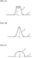
- FIGS. 2A, 2B, and 2C are cross-sectional views schematically showing an example of the surface shape of the protuberance 20.
- the surface shape of the protuberance 20 may have a concave portion in the center, or as shown in FIG. 2B , may be a bell shape with a Gaussian distribution (normal distribution curve), or as shown in FIG. 2C , may be spherical, and further may be a shape of coexistence of them.
- the bell shape having a Gaussian distribution also includes a shape having a curve that can be approximated to a Gaussian distribution.
- the spherical shape includes not only a shape whose surface is a perfect sphere, but also a shape whose surface can be approximated to a spherical surface.
- the diameter D of the protuberance 20 is, for example, 0.6 to 2.0 mm, and the height h is, for example, 0.1 to 10 ⁇ m. Further, when the surface shape of the protuberance 20 has a concave portion in the center as shown in FIG. 2A , the depth d of the concave portion is, for example, 0.1 to 5 ⁇ m.
- FIG. 3 is a flow chart showing an example of a method for manufacturing the spectacle lens 100 according to the present embodiment.
- the method for manufacturing the spectacle lens 100 of the present embodiment includes, for example, a lens substrate forming step S101, a hard coat film forming step S102, a protuberance forming step S103, and an antireflection film forming step S104.
- the lens substrate forming step S101 is, for example, a step of forming a lens substrate by performing cast polymerization using a molding mold such as a glass mold die.
- the lens substrate may be, for example, a plastic lens substrate or a glass lens substrate.
- the glass lens substrate may be, for example, a lens substrate comprising inorganic glass.
- a plastic lens substrate is preferable from a viewpoint of light weight and resistance to cracking.
- plastic lens substrate examples include styrene resins including (meth)acrylic resins, polycarbonate resins, allyl resins, allyl carbonate resins such as diethylene glycol bisallyl carbonate resin (CR-39), vinyl resins, polyester resins, polyether resins, urethane resins obtained by reacting an isocyanate compound with a hydroxy compound such as diethylene glycol, thiourethane resins obtained by reacting an isocyanate compound with a polythiol compound, and cured products obtained by curing curable compositions containing (thio)epoxy compounds having one or more disulfide bonds per molecule (generally also referred to as transparent resins).
- styrene resins including (meth)acrylic resins, polycarbonate resins, allyl resins, allyl carbonate resins such as diethylene glycol bisallyl carbonate resin (CR-39), vinyl resins, polyester resins, polyether resins, urethane resins obtained by reacting an
- a curable composition may also be referred to as a polymerizable composition.
- the lens substrate an undyed one (colorless lens) may be used, or a dyed one (dyed lens) may be used.
- the thickness and diameter of the lens substrate are not particularly limited, for example, the thickness (center thickness) may be about 1 to 30 mm, and the diameter may be about 50 to 100 mm.
- the refractive index of the lens substrate may be, for example, about 1.60 to 1.75. However, the refractive index of the lens substrate is not limited to this range, and may be within this range or vertically apart from this range. In the present invention and this specification, the refractive index refers to the refractive index for light with a wavelength of 500 nm.
- a molding mold having concave portions for forming minute convex portions is used in a conventional method for manufacturing a spectacle lens for suppressing the progression of myopia.
- the molding mold having concave portions is not required to be used in the lens substrate forming step S101 of the present embodiment. This contributes to reducing a manufacturing cost of the spectacle lens 100.
- the molding mold suited to the design of the minute convex portions is not required to be respectively prepared, thereby making the molding mold versatile.
- a metal mold that has undergone a cutting process has been used.
- a molding mold such as a glass mold can be used in addition to the metal mold. Accordingly, as described above, a wide variety of lens substrate materials can be used. That is, it can be said that the degree of freedom in designing the spectacle lens 100, which is a lens for suppressing the progression of myopia, can be improved.
- thermoplastic resin such as polycarbonate resin can be molded in a short period of time by injection molding, and can be used for mass production of the lens substrates without preparing a large number of expensive metal molds.
- a long time is required to cause a reaction of a polymerization-type resin material (for example, thermosetting resin) other than polycarbonate resin, resulting in low productivity.
- a large number of expensive metal molds are required to be prepared and meanwhile, according to the present invention, preparation of the metal mold is not required.
- the effect of the present invention is remarkably obtained in the case of using a resin material such as a high refractive index material (often a thermosetting resin) having a refractive index exceeding 1.60.
- the hard coat film forming step S102 is, for example, a step of forming a resin-containing hard coat film on at least one main surface (preferably both main surfaces) of the lens substrate formed in the lens substrate forming step S101.
- the lens substrate forming step S101 and the hard coat film forming step S102 may be combined to be a lens substrate preparation step of preparing a lens substrate in which a resin-containing hard coat film is formed on at least one or the main surfaces.
- the method of forming the hard coat film is not particularly limited, and for example, a spin coating, a dipping, etc., can be used.
- the hard coat film includes a cured film formed by curing a curable composition containing a curable compound.
- the hard coat film contributes to improving the durability of a spectacle lens.
- the curable compound means a compound having a curable functional group
- the curable composition means a composition containing one or more curable compounds.
- Examples of the curable composition for forming the hard coat film include a curable composition containing an organosilicon compound as a curable compound, and also include a curable composition containing metal oxide particles together with the organosilicon compound.
- An example of the curable composition capable of forming a hard coat film is the curable composition described in JP-A-63-10640 .
- organosilicon compound includes an organosilicon compound represented by the following general formula (I) and a hydrolyzate thereof.
- R 1 represents an organic group having a glycidoxy group, an epoxy group, a vinyl group, a methacryloxy group, an acryloxy group, a mercapto group, an amino group, a phenyl group, etc.
- R 2 represents an alkyl group having 1 to 4 carbon atoms, an acyl group having 1 to 4 carbon atoms or an aryl group having 6 to 10 carbon atoms
- R 3 represents an alkyl group having 1 to 6 carbon atoms or an aryl group having 6 to 10 carbon atoms
- a and b represent 0 or 1 respectively.
- the alkyl group having 1 to 4 carbon atoms represented by R 2 is a linear or branched alkyl group, and specific examples thereof include a methyl group, an ethyl group, a propyl group, a butyl group, etc.
- Examples of the acyl groups having 1 to 4 carbon atoms represented by R 2 include an acetyl group, a propionyl group, an oleyl group, a benzoyl group, etc.
- Examples of the aryl group having 6 to 10 carbon atoms represented by R 2 include a phenyl group, a xylyl group, a tolyl group, etc.
- the alkyl group having 1 to 6 carbon atoms represented by R 3 is a linear or branched alkyl group, and specific examples thereof include a methyl group, an ethyl group, a propyl group, a butyl group, a pentyl group, and a hexyl.
- the aryl group having 6 to 10 carbon atoms represented by R 3 includes, for example, a phenyl group, a xylyl group, a tolyl group, etc.
- Specific examples of the compound represented by formula (I) include compounds described in paragraph 0073 of JP-A-2007-077327 . Since the organosilicon compound represented by the general formula (I) has a curable group, a hard coat film can be formed by performing a curing treatment after coating.
- Metal oxide particles can contribute to adjusting the refractive index and improving the hardness of a cured film.
- Specific examples of the metal oxide particles include tungsten oxide (WO 3 ), zinc oxide (ZnO), silicon oxide (SiO 2 ), aluminum oxide (Al 2 O 3 ), titanium oxide (TiO 2 ), zirconium oxide (ZrO 2 ), tin oxide (SnO 2 ), beryllium oxide (BeO), antimony oxide (SbzOs), etc., and single or a combination of two or more kinds of metal oxide particles can be used.
- the particle size of the metal oxide particles is preferably in a range of 5 to 30 nm from a viewpoint of achieving both scratch resistance and optical properties of the hard coat film.
- the content of the metal oxide particles in the curable composition can be appropriately set in consideration of the refractive index and hardness of the hard coat film to be formed, and generally, the content may be about 5 to 80% by mass based on a solid content of the curable composition. Further, the metal oxide particles are preferably colloidal particles, from a viewpoint of dispersibility in the hard coat film.
- the hard coat film in order to form a hard coat film on the lens substrate on which the minute convex portions are formed, the hard coat film was required to be thin (for example, the film thickness of the hard coat film was less than 2 ⁇ m) so that the minute convex portions would not be buried in the hard coat film.
- the hard coat film forming step S102 of the present embodiment since the hard coat film is formed on the lens substrate on which the minute convex portions are not formed, there is no particular limit in the thickness of the hard coat film (for example, the film thickness of the hard coat film may be 0.1 to 100 ⁇ m).
- the degree of freedom is improved in designing the spectacle lens 100, which is a lens for suppressing the progression of myopia.
- the scratch resistance of the spectacle lens 100 is improved. Further, liquid puddles do not occur around the minute convex portions, and the risk of not being able to obtain defocus as designed can be reduced.
- the protuberance forming step S103 is, for example, a step of irradiating the hard coat film formed in the hard coat film forming step S102 with a laser to form, on the hard coat film, a plurality of protuberances 20 in which at least one of the lens substrate or the hard coat film is protruded. Due to containing resin, the hard coat film may be locally softened and expanded by laser irradiation, thereby forming the protuberances 20. That is, the hard coat film formed on the lens substrate thermally expands due to laser irradiation, and the film thickness is locally increased, and the surface of the hard coat film is protruded to form the protuberances 20.
- the protuberance 20 in this case is a protruded surface of the hard coat film.
- the lens substrate due to containing resin and having higher laser absorption than the hard coat film, the lens substrate is considered to be softened and expanded, thereby pushing up the hard coat film, resulting in forming the protuberance 20.
- the lens substrate may be thermally expanded by laser irradiation, and the hard coat film may cover the formed protuberances on the surface of the lens substrate, resulting in forming the protuberances 20. That is, in this case, the protuberances 20 are formed due to thermal expansion of the lens substrate to form surface protuberances, and covering the surface protuberances with a hard coat film.
- the present embodiment mainly shows the case of the protuberances of the hard coat film.
- the laser used in the protuberance forming step S103 is preferably a CO 2 laser.
- the hard coat film has a higher laser absorption rate, which makes it easier to soften and expand the hard coat film, thereby making it easy to form the protuberances 20.
- Lasers other than CO 2 laser for example, infrared laser, green laser, ultraviolet laser, etc. may be used in the protuberance forming step S103. In this case, it is preferable to coat the hard coat film with an absorbent that facilitates laser absorption.
- the laser irradiation when forming one protuberance 20, the laser irradiation may be performed at a fixed point, or the laser irradiation may be performed while applying scanning using a galvanometer scanner, etc.
- a radiation intensity distribution of the laser used in the protuberance forming step S103 is preferably Gaussian distribution. This makes it easier to smoothly protrude the edge of the protuberance 20. Therefore due to the formation of the protuberances 20, the influence on the vision through the spectacle lens 100 can be reduced.
- a beam shaper, etc. may be used to control the radiation intensity distribution of the laser.
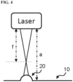
- FIG. 4 is a view schematically showing the state of laser irradiation in the protuberance forming step S103.
- the protuberance forming step S103 it is preferable to perform laser irradiation, with a distance between a laser irradiation device and the hard coat film (hereinafter referred to as irradiation distance a) being larger or smaller than a focal length f of the laser. That is, it is preferable to perform laser irradiation, with the hard coat film being shifted with respect to the focus position of the laser irradiation device either farther or closer.
- the size and shape of the protuberance 20 can be adjusted by controlling the distribution of the irradiation energy on the hard coat film.
- the irradiation distance a being longer than the focal length f, and the hard coat film being shifted to farther from the focus position of the laser irradiation device.
- the irradiation distance a of the laser it is preferable to set the irradiation distance a of the laser to be the focal length f ⁇ 0.1 to 30 mm of the laser.
- the size and surface shape of the protuberance 20 can be controlled by adjusting the laser output, irradiation distance, irradiation time, radiation intensity distribution, etc.
- the surface shape of the protuberance 20 can be made into a bell shape having a Gaussian distribution as shown in FIG. 2B .
- the surface shape of the protuberance 20 can be made to have a concave portion in the center as shown in FIG. 2A . It is considered that the softening of the hard coat film progresses remarkably in the vicinity of the center of the laser, causing melting of the hard coat film. The surface shape having a concave portion in the center is thus obtained.
- the design of the minute convex portions is limited depending on the design of the molding mold.
- the design of the protuberance 20 is not limited because the protuberance 20 is formed as a retrofit by laser processing without using the molding mold having concave portions. Accordingly, even when using the same molding mold, the design of the protuberance 20 can be flexibly changed. In other words, it can be said that the degree of freedom is improved in designing the spectacle lens 100, which is a lens for suppressing the progression of myopia.
- the laser irradiation may soften and expand the lens substrate as well as the hard coat film.
- the hard coat film forming step S102 it is preferable to form a hard coat film having a larger coefficient of thermal expansion than the coefficient of thermal expansion of the lens substrate.
- the antireflection film forming step S104 is, for example, a step of forming an antireflection film on the hard coat film on which the protuberances 20 are formed in the protuberance forming step S103.
- various films such as a water-repellent or a hydrophilic antifouling film and an antifogging film may be formed. A known technique can be applied to the method of forming these coating films. Note that the antireflection film forming step S104 can be omitted.
- the antireflection film forming step S104 is preferably performed in a low temperature environment, for example, about 80 to 100 degrees. Thereby, the protuberance 20 formed in the protuberance forming step S103 is softened again, and the risk of deformation, etc., occurring can be reduced.
- the antireflection film (and various coating films described above) formed in the antireflection film forming step S104 is considerably thinner (for example, about 0.1 ⁇ m) than the height of the protuberance 20, the risk of the protuberance 20 being buried by the antireflection film, etc., can be reduced.
- the spectacle lens 100 including the base portion 10 (the portion where the protuberance 20 is not formed in the protuberance forming step S103) and the plurality of protuberances 20, can be manufactured. Since the plurality of protuberances 20 have the property that the light beams passing through at least a part of the protuberance 20 is incident on the retina as a divergent light, the spectacle lens 100 can suppress the progression of myopia. Accordingly, by the method for manufacturing the spectacle lens 100 of the present embodiment, the spectacle lens 100 capable of suppressing the progression of myopia can be manufactured without using the molding mold having concave portions.
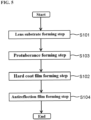
- FIG. 5 is a flow chart showing an example of a method for manufacturing the spectacle lens 100 according to the present embodiment.
- the method for manufacturing the spectacle lens 100 of the present embodiment includes, for example, the lens substrate forming step S 101, the protuberance forming step S103, the hard coat film forming step S102, and the antireflection film forming step S104, in which an order of the hard coat film forming step S102 and the protuberance forming step S103 is reversed from that of the first embodiment.
- the lens substrate forming step S101 of the present embodiment is, like the first embodiment, a step of forming a lens substrate by performing cast polymerization using a molding mold such as a glass mold.
- a resin-containing plastic lens substrate is used as the lens substrate.
- the protuberance forming step S103 of the present embodiment is, for example, a step of irradiating the lens substrate formed in the lens substrate forming step S101 with a laser to form a plurality of protuberances 20 in which the lens substrate is protruded.
- a laser due to the resin-containing lens substrate, it is considered that the lens substrate is locally softened and expanded by the laser irradiation, thereby forming the protuberances 20.
- the laser irradiation can be performed in the same manner as in the first embodiment.
- the hard coat film forming step S102 of the present embodiment is, for example, a step of forming a hard coat film on at least one main surface (preferably both main surfaces) of the lens substrate formed in the lens substrate forming step S101.
- a resin-containing hard coat film is formed on at least one main surface of the lens substrate including the protuberances 20.
- a hard coat film containing UV curable resin ultraviolet curable resin
- UV curable resin ultraviolet curable resin
- the protuberances 20 may be softened again and deformed because the hard coat film is heated during curing.
- the hard coat film containing UV curable resin the hard coat film can be photo-cured. Therefore, the risk of softening again and deforming the protuberances 20 can be reduced.
- the hard coat film may be formed so as to fill the concave portion of the protuberance 20 in the hard coat film forming step S102 of the present embodiment.
- the anti-reflection film forming step S104 of the present embodiment can be performed in the same manner as in the first embodiment, so the description thereof is omitted.
- the spectacle lens 100 including the base portion 10 and the plurality of protuberances 20 can also be manufactured by the above steps, as in the first embodiment. Accordingly, the method for manufacturing the spectacle lens 100 according to the present embodiment also realize the manufacture of the spectacle lens 100 capable of suppressing the progression of myopia without using a molding mold having concave portions.
- the spectacle lens 100 has a fixed design of the plurality of protuberances 20, but in the spectacle lens 100, the design of the plurality of protuberances 20 may be changed. Specifically, for example, the diameter D of the protuberance 20 may be increased from the center portion toward the peripheral portion of the spectacle lens 100.
- a lens substrate having a hard coat film formed on both main surfaces was prepared.
- a plastic lens substrate having a refractive index of 1.60 was used as the lens substrate.
- the hard coat film was formed using a thermosetting coating agent.
- the hard coat film of the lens substrate prepared in (1) was irradiated with a CO 2 laser to form a plurality of protuberances 20, and samples 1 to 12 were obtained.
- the used CO 2 laser had a focal length of 145 mm, an average output of 12 W, a peak wavelength of 10.6 ⁇ m, with a radiation intensity distribution being the Gaussian distribution.
- a fixed point irradiation of CO 2 laser was applied for 50 to 200 milliseconds.
- Irradiation conditions (irradiation distance, output) for samples 1 to 12 are shown in Table 1. In Table 1, the irradiation distance is shown with the focal length of the CO 2 laser as a reference (0 mm), and the output is shown with the average output of the CO 2 laser as a reference (100%).
- the surface shape (diameter D, height h, depth d of the concave portion) was measured for the protuberances 20 (samples 1 to 12) formed in (2) using a surface profile measuring machine (Talysurf CCIMP-HSXL).
- Table 1 shows the results.
- A represents a case of having a concave portion in the center
- B represents a case of not having a concave portion in the center (for example, a bell shape with a Gaussian distribution as shown in FIG. 2B , or a spherical shape as shown in FIG. 2C )
- A-B represents a case of coexistence of A and B.
- the size and surface shape of the protuberance 20 could be controlled by adjusting the laser irradiation conditions (irradiation distance, output). Accordingly, it was confirmed that the design freedom of the spectacle lens 100, which is a lens for suppressing the progress of myopia, could be improved by forming the protuberance 20 as a retrofit by laser processing without using a molding mold having concave portions.
Landscapes
- Engineering & Computer Science (AREA)
- Health & Medical Sciences (AREA)
- Physics & Mathematics (AREA)
- Ophthalmology & Optometry (AREA)
- Mechanical Engineering (AREA)
- General Physics & Mathematics (AREA)
- Optics & Photonics (AREA)
- Manufacturing & Machinery (AREA)
- General Health & Medical Sciences (AREA)
- Toxicology (AREA)
- Eyeglasses (AREA)
Abstract
Description
- The present invention relates to a method for manufacturing a spectacle lens, and a spectacle lens.
- Patent document 1 describes a spectacle lens that suppresses a progression of refractive error such as myopia. Specifically, for example, spherical minute convex portions having a diameter of about 1 mm are formed on a convex surface, which is an object-side surface of the spectacle lens. In the spectacle lens, light beams incident from the object-side surface are normally emitted from an eyeball-side surface and focused on a retina of a wearer. On the other hand, light beams that have passed through the minute convex portions are focused at a position closer to the object-side (front-side) than a wearer's retina. As a result, the progression of myopia is suppressed.
- Further, Patent document 2 describes a method for manufacturing a spectacle lens molding mold having concave portions for forming the above minute convex portions.
-
- [Patent Document 1]
US Application Publication No. 2017/0131567 - [Patent Document 2] International Publication No.
2019/124353 - A manufacturing method described in Patent Document 2 involves a problem such that a material and design type of a lens substrate are limited due to use of a metal molding mold (hereinafter also referred to as a metal mold), and also involves a problem such that it is difficult to prepare many types of convex molds, resulting in a limited convex curve of a spectacle lens, thereby limiting an optical prescription of the spectacle lens, due to a high cost of manufacturing metal molds.
- One embodiment of the present invention is to provide a technique of manufacturing a spectacle lens capable of suppressing a progression of myopia without using a molding mold having concave portions.
- A first aspect of the present invention provides a method for manufacturing a spectacle lens, including:
- preparing a lens substrate having a resin-containing hard coat film formed on at least one main surface; and
- forming a plurality of protuberances in which at least one of the lens substrate or the hard coat film is protruded, by irradiating the hard coat film with a laser.
- A second aspect of the present invention provides the method for manufacturing a spectacle lens according to the first aspect, wherein in the formation of the protuberances, the protuberances are formed due to local expanding of the hard coat film by laser irradiation.
- A third aspect of the present invention provides the method for manufacturing a spectacle lens according to the first aspect, wherein in the formation of the protuberances, the protuberances are formed due to local expanding of the lens substrate by laser irradiation.
- A fourth aspect of the present invention provides a method for manufacturing a spectacle lens, including:
- preparing a lens substrate containing a resin; and
- irradiating the lens substrate with a laser to form a plurality of protuberances in which the lens substrate is protruded.
- A fifth aspect of the present invention provides the method for manufacturing a spectacle lens according to the fourth aspect, further including:
forming a hard coat film on at least one main surface of the lens substrate including the protuberances in which the lens substrate is protruded. - A sixth aspect of the present invention provides the method for manufacturing a spectacle lens according to the fifth aspect, wherein the hard coat film contains ultraviolet curable resin.
- A seventh aspect of the present invention provides the method for manufacturing a spectacle lens according to any one of the first to sixth aspects, wherein the laser is a CO2 laser.
- An eighth aspect of the present invention provides the method for manufacturing a spectacle lens according to any one of the first to seventh aspects, wherein a radiation intensity distribution of the laser is a Gaussian distribution.
- A nineth aspect of the present invention provides the method for manufacturing a spectacle lens according to any one of the first to eighth aspects, wherein in the formation of the protuberances, laser irradiation is performed, with an irradiation distance of the laser set to be larger or smaller than a focal length of the laser.
- A tenth aspect of the present invention provides the method for manufacturing a spectacle lens according to any one of the first to nineth aspects, wherein
- the spectacle lens is a myopia progression suppressing lens, and
- the protuberances have a property that light beams passing through at least a part of the protuberance are incident on the retina as a divergent light.
- An eleventh aspect of the present invention provides a spectacle lens, including:
- a base portion where a light incident from an object-side surface is emitted from an eyeball side surface and converges on a retina through an eyeball; and
- a plurality of protuberances in contact with the base portion and having a property that light beams passing through at least a part of the protuberance are incident on the retina as a divergent light,
- the spectacle lens including a lens substrate and a hard coat film on the lens substrate, and
- the plurality of protuberances being the protuberances in which a surface of the hard coat film is protruded.
- A twelfth aspect of the present invention provides a spectacle lens, including:
- a base portion where a luminous incident from an object-side surface is emitted from an eyeball side surface and converges on a retina through an eyeball.; and
- a plurality of protuberances that are in contact with the base portion and have a property that light beams passing through at least a part of the protuberance are incident on the retina as a divergent light,
- the spectacle lens including a lens substrate and a hard coat film on the lens substrate, and
- the plurality of protuberance being the protuberances in which a surface protuberance due to thermal expansion of the lens substrate is coated with the hard coat film.
- A thirteenth aspect of the present invention provides the spectacle lens according to the twelfth aspect, wherein the spectacle lens is a myopia progression suppressing lens, and the protuberances have a configuration such that light beams passing through at least a part of the protuberance converge before reaching the retina through the eyeball and are incident on the retina as a divergent light.
- A fourteenth aspect of the present invention provides the spectacle lens according to the eleventh or twelfth aspect, wherein the protuberance has a surface shape of including a concave portion in a center.
- A fifteenth aspect of the present invention provides the spectacle lens according to the eleventh or twelfth aspect, wherein a surface shape of the plurality of protuberances is a bell shape having a Gaussian distribution.
- A sixteenth aspect of the present invention provides the spectacle lens according to the eleventh or twelfth aspect, wherein a surface shape of the plurality of protuberances is a spherical shape.
- According to one embodiment of the present invention, there is provided a technique of manufacturing a spectacle lens capable of suppressing a progression of myopia without using a molding mold having concave portions.
-
-
FIG. 1 is a plan view of an object-side surface of aspectacle lens 100 according to a first embodiment of the present invention. -
FIG. 2A is a cross-sectional view schematically showing an example of a surface shape of aprotuberance 20 according to the first embodiment of the present invention. -
FIG. 2B is a cross-sectional view schematically showing an example of the surface shape of theprotuberance 20 according to the first embodiment of the present invention. -
FIG. 2C is a cross-sectional view schematically showing an example of the surface shape of theprotuberance 20 according to the first embodiment of the present invention. -
FIG. 3 is a flow chart showing an example of a method for manufacturing thespectacle lens 100 according to the first embodiment of the present invention. -
FIG. 4 is a view schematically showing a state of performing laser irradiation in a protuberance forming step S103 according to the first embodiment of the present invention. -
FIG. 5 is a flow chart showing an example of a method for manufacturing thespectacle lens 100 according to a second embodiment of the present invention. - Next, one embodiment of the present invention will be described below with reference to the drawings. The present invention is not limited to these examples, but is indicated by the scope of the claims, and is intended to include all modifications within the meaning and scope of equivalents to the scope of the claims.
- The spectacle lens described herein has an object-side surface and an eyeball-side surface. The "object-side surface" means a surface located on the object-side when a spectacle having spectacle lenses are worn by a wearer, and the "eyeball-side surface" is the opposite, ie the surface that is located on the eyeball-side when the spectacle having spectacle lenses are worn by the wearer. This relationship also applies to a lens substrate that serves as the basis of the spectacle lens. That is, the lens substrate also has the object-side surface and the eyeball-side surface.
- In the present specification, "A to B" means a numerical range of "A or more and B or less".
-
FIG. 1 is a plan view of the object-side surface of thespectacle lens 100 according to the present embodiment. Thespectacle lens 100 of the present embodiment includes abase portion 10 and a plurality ofprotuberances 20. Thebase portion 10 is the portion where light beams incident from the object-side surface are emitted from the eyeball side surface, and converges on a retina through an eyeball. The plurality ofprotuberances 20 are the protuberances in contact with thebase portion 10 and having a property that the light beams passing through at least a part of the protuberance are incident on the retina as a divergent light. For example, the light beams passing through at least a part of theprotuberance 20 converges through an eyeball before reaching the retina (position closer to the object-side than the retina) and are incident on the retina as a divergent light. - The
base portion 10 has an optical surface determined based on a wearer's prescription, that is, has a portion having a shape capable of realizing a prescribed refractive power of the wearer, which is the portion corresponding to a first refractive region of Patent document 1. - The
protuberance 20 is a region at least a part of which does not allow a base power image to be converged at a converging position. Theprotuberance 20 is a portion having a protruded shape, which is a portion corresponding to the minute convex portions described in Patent document 1. Thespectacle lens 100 of the present embodiment is a myopia progression suppressing lens, like the spectacle lens described in Patent document 1. Similarly to the minute convex portions of Patent document 1, the plurality ofprotuberances 20 of the present embodiment may be formed on at least one of the object-side surface or the eyeball-side surface, out of the two main surfaces of thespectacle lens 100. For example, the present embodiment shows a case where the plurality ofprotuberances 20 are provided only on the object-side surface (convex surface) of thespectacle lens 100. - The plurality of
protuberances 20 are arranged, for example, in an island shape (that is, separated from each other without adjacent to each other). An arrangement mode of the plurality ofprotuberances 20 is not particularly limited. For example, as shown inFIG. 1 , the present embodiment shows a case where theprotuberances 20 are arranged independently and sparsely so that the centers of theprotuberances 20 are the vertices of an equilateral triangle (hereinafter also referred to as an equilateral triangular arrangement). The number ofprotuberances 20 included in thespectacle lens 100 is not particularly limited. - As described in
FIG. 1 of Patent document 1, a region in which theprotuberance 20 is not formed may be provided in the center portion of thespectacle lens 100, or as described in FIG. 10 of Patent document 1, a region in which theprotuberance 20 is not formed, may not be provided in the center portion of thespectacle lens 100. For example, as shown inFIG. 1 , the present embodiment shows a case where the region in which theprotuberance 20 is not formed is provided in the center portion of thespectacle lens 100. In the present embodiment, the center portion of thespectacle lens 100 means a lens center (geometric center, optical center, or centering center) of thespectacle lens 100 and the vicinity thereof. For example, the present embodiment shows a case where the line of sight of the wearer of thespectacle lens 100 passes through the center of the lens when viewed from the front. -
FIGS. 2A, 2B, and 2C are cross-sectional views schematically showing an example of the surface shape of theprotuberance 20. As shown inFIG. 2A , the surface shape of theprotuberance 20 may have a concave portion in the center, or as shown inFIG. 2B , may be a bell shape with a Gaussian distribution (normal distribution curve), or as shown inFIG. 2C , may be spherical, and further may be a shape of coexistence of them. In this specification, the bell shape having a Gaussian distribution also includes a shape having a curve that can be approximated to a Gaussian distribution. Further, the spherical shape includes not only a shape whose surface is a perfect sphere, but also a shape whose surface can be approximated to a spherical surface. - The diameter D of the
protuberance 20 is, for example, 0.6 to 2.0 mm, and the height h is, for example, 0.1 to 10 µm. Further, when the surface shape of theprotuberance 20 has a concave portion in the center as shown inFIG. 2A , the depth d of the concave portion is, for example, 0.1 to 5 µm. -
FIG. 3 is a flow chart showing an example of a method for manufacturing thespectacle lens 100 according to the present embodiment. As shown inFIG. 3 , the method for manufacturing thespectacle lens 100 of the present embodiment includes, for example, a lens substrate forming step S101, a hard coat film forming step S102, a protuberance forming step S103, and an antireflection film forming step S104. - The lens substrate forming step S101 is, for example, a step of forming a lens substrate by performing cast polymerization using a molding mold such as a glass mold die.
- Various lens substrates commonly used for spectacle lenses can be used, as the lens substrate. The lens substrate may be, for example, a plastic lens substrate or a glass lens substrate. The glass lens substrate may be, for example, a lens substrate comprising inorganic glass. As the lens substrate, a plastic lens substrate is preferable from a viewpoint of light weight and resistance to cracking. Examples of the plastic lens substrate include styrene resins including (meth)acrylic resins, polycarbonate resins, allyl resins, allyl carbonate resins such as diethylene glycol bisallyl carbonate resin (CR-39), vinyl resins, polyester resins, polyether resins, urethane resins obtained by reacting an isocyanate compound with a hydroxy compound such as diethylene glycol, thiourethane resins obtained by reacting an isocyanate compound with a polythiol compound, and cured products obtained by curing curable compositions containing (thio)epoxy compounds having one or more disulfide bonds per molecule (generally also referred to as transparent resins). A curable composition may also be referred to as a polymerizable composition. As the lens substrate, an undyed one (colorless lens) may be used, or a dyed one (dyed lens) may be used. Although the thickness and diameter of the lens substrate are not particularly limited, for example, the thickness (center thickness) may be about 1 to 30 mm, and the diameter may be about 50 to 100 mm. The refractive index of the lens substrate may be, for example, about 1.60 to 1.75. However, the refractive index of the lens substrate is not limited to this range, and may be within this range or vertically apart from this range. In the present invention and this specification, the refractive index refers to the refractive index for light with a wavelength of 500 nm.
- Here, in a conventional method for manufacturing a spectacle lens for suppressing the progression of myopia, a molding mold having concave portions for forming minute convex portions is used. In contrast, in the lens substrate forming step S101 of the present embodiment, the molding mold having concave portions is not required to be used. This contributes to reducing a manufacturing cost of the
spectacle lens 100. Further, the molding mold suited to the design of the minute convex portions is not required to be respectively prepared, thereby making the molding mold versatile. - Further, in a conventional spectacle lens manufacturing method for suppressing the progression of myopia, in order to accurately apply processing to the molding mold to obtain concave portions for forming the minute convex portions, a metal mold that has undergone a cutting process has been used. In contrast, in the lens substrate forming step S101 of the present embodiment, it is not required to apply processing of the concave portions for forming the minute convex portions, and therefore a molding mold such as a glass mold can be used in addition to the metal mold. Accordingly, as described above, a wide variety of lens substrate materials can be used. That is, it can be said that the degree of freedom in designing the
spectacle lens 100, which is a lens for suppressing the progression of myopia, can be improved. Particularly, in the case of using the metal mold, there is a concern that the material for the lens substrate will be limited to polycarbonate resin due to a manufacturing problem. Specifically, for example, thermoplastic resin such as polycarbonate resin can be molded in a short period of time by injection molding, and can be used for mass production of the lens substrates without preparing a large number of expensive metal molds. However, a long time is required to cause a reaction of a polymerization-type resin material (for example, thermosetting resin) other than polycarbonate resin, resulting in low productivity. Then, in order to solve this problem and cope with mass production of lens substrates, a large number of expensive metal molds are required to be prepared and meanwhile, according to the present invention, preparation of the metal mold is not required. Accordingly, regardless of the material of the lens substrate, efficient manufacturing is realized under a condition that does not excessively increase the manufacturing cost. For example, the effect of the present invention is remarkably obtained in the case of using a resin material such as a high refractive index material (often a thermosetting resin) having a refractive index exceeding 1.60. - The hard coat film forming step S102 is, for example, a step of forming a resin-containing hard coat film on at least one main surface (preferably both main surfaces) of the lens substrate formed in the lens substrate forming step S101. The lens substrate forming step S101 and the hard coat film forming step S102 may be combined to be a lens substrate preparation step of preparing a lens substrate in which a resin-containing hard coat film is formed on at least one or the main surfaces.
- In the hard coat film forming step S102, the method of forming the hard coat film is not particularly limited, and for example, a spin coating, a dipping, etc., can be used.
- The hard coat film includes a cured film formed by curing a curable composition containing a curable compound. The hard coat film contributes to improving the durability of a spectacle lens. The curable compound means a compound having a curable functional group, and the curable composition means a composition containing one or more curable compounds.
- Examples of the curable composition for forming the hard coat film include a curable composition containing an organosilicon compound as a curable compound, and also include a curable composition containing metal oxide particles together with the organosilicon compound. An example of the curable composition capable of forming a hard coat film is the curable composition described in
JP-A-63-10640 - Further, one aspect of the organosilicon compound includes an organosilicon compound represented by the following general formula (I) and a hydrolyzate thereof.
(R1)a(R3)bSi(OR2)4-(a+b) (I)
- In general formula (I), R1 represents an organic group having a glycidoxy group, an epoxy group, a vinyl group, a methacryloxy group, an acryloxy group, a mercapto group, an amino group, a phenyl group, etc., R2 represents an alkyl group having 1 to 4 carbon atoms, an acyl group having 1 to 4 carbon atoms or an aryl group having 6 to 10 carbon atoms, R3 represents an alkyl group having 1 to 6 carbon atoms or an aryl group having 6 to 10 carbon atoms, and a and b represent 0 or 1 respectively.
- The alkyl group having 1 to 4 carbon atoms represented by R2 is a linear or branched alkyl group, and specific examples thereof include a methyl group, an ethyl group, a propyl group, a butyl group, etc. Examples of the acyl groups having 1 to 4 carbon atoms represented by R2 include an acetyl group, a propionyl group, an oleyl group, a benzoyl group, etc. Examples of the aryl group having 6 to 10 carbon atoms represented by R2 include a phenyl group, a xylyl group, a tolyl group, etc. The alkyl group having 1 to 6 carbon atoms represented by R3 is a linear or branched alkyl group, and specific examples thereof include a methyl group, an ethyl group, a propyl group, a butyl group, a pentyl group, and a hexyl. The aryl group having 6 to 10 carbon atoms represented by R3 includes, for example, a phenyl group, a xylyl group, a tolyl group, etc. Specific examples of the compound represented by formula (I) include compounds described in paragraph 0073 of
JP-A-2007-077327 - Metal oxide particles can contribute to adjusting the refractive index and improving the hardness of a cured film. Specific examples of the metal oxide particles include tungsten oxide (WO3), zinc oxide (ZnO), silicon oxide (SiO2), aluminum oxide (Al2O3), titanium oxide (TiO2), zirconium oxide (ZrO2), tin oxide (SnO2), beryllium oxide (BeO), antimony oxide (SbzOs), etc., and single or a combination of two or more kinds of metal oxide particles can be used. The particle size of the metal oxide particles is preferably in a range of 5 to 30 nm from a viewpoint of achieving both scratch resistance and optical properties of the hard coat film. The content of the metal oxide particles in the curable composition can be appropriately set in consideration of the refractive index and hardness of the hard coat film to be formed, and generally, the content may be about 5 to 80% by mass based on a solid content of the curable composition. Further, the metal oxide particles are preferably colloidal particles, from a viewpoint of dispersibility in the hard coat film.
- Here, in a conventional spectacle lens manufacturing method for suppressing the progression of myopia, in order to form a hard coat film on the lens substrate on which the minute convex portions are formed, the hard coat film was required to be thin (for example, the film thickness of the hard coat film was less than 2 µm) so that the minute convex portions would not be buried in the hard coat film. In contrast, in the hard coat film forming step S102 of the present embodiment, since the hard coat film is formed on the lens substrate on which the minute convex portions are not formed, there is no particular limit in the thickness of the hard coat film (for example, the film thickness of the hard coat film may be 0.1 to 100 µm). That is, it can be said that the degree of freedom is improved in designing the
spectacle lens 100, which is a lens for suppressing the progression of myopia. Particularly, by setting the film thickness of the hard coat film to 2 µm or more, the scratch resistance of thespectacle lens 100 is improved. Further, liquid puddles do not occur around the minute convex portions, and the risk of not being able to obtain defocus as designed can be reduced. - The protuberance forming step S103 is, for example, a step of irradiating the hard coat film formed in the hard coat film forming step S102 with a laser to form, on the hard coat film, a plurality of
protuberances 20 in which at least one of the lens substrate or the hard coat film is protruded. Due to containing resin, the hard coat film may be locally softened and expanded by laser irradiation, thereby forming theprotuberances 20. That is, the hard coat film formed on the lens substrate thermally expands due to laser irradiation, and the film thickness is locally increased, and the surface of the hard coat film is protruded to form theprotuberances 20. That is, theprotuberance 20 in this case is a protruded surface of the hard coat film. Further, due to containing resin and having higher laser absorption than the hard coat film, the lens substrate is considered to be softened and expanded, thereby pushing up the hard coat film, resulting in forming theprotuberance 20. In this case, the lens substrate may be thermally expanded by laser irradiation, and the hard coat film may cover the formed protuberances on the surface of the lens substrate, resulting in forming theprotuberances 20. That is, in this case, theprotuberances 20 are formed due to thermal expansion of the lens substrate to form surface protuberances, and covering the surface protuberances with a hard coat film. - The present embodiment mainly shows the case of the protuberances of the hard coat film.
- The laser used in the protuberance forming step S103 is preferably a CO2 laser. By using the CO2 laser, the hard coat film has a higher laser absorption rate, which makes it easier to soften and expand the hard coat film, thereby making it easy to form the
protuberances 20. Lasers other than CO2 laser (for example, infrared laser, green laser, ultraviolet laser, etc.) may be used in the protuberance forming step S103. In this case, it is preferable to coat the hard coat film with an absorbent that facilitates laser absorption. - In the protuberance forming step S103, when forming one
protuberance 20, the laser irradiation may be performed at a fixed point, or the laser irradiation may be performed while applying scanning using a galvanometer scanner, etc. - A radiation intensity distribution of the laser used in the protuberance forming step S103 is preferably Gaussian distribution. This makes it easier to smoothly protrude the edge of the
protuberance 20. Therefore due to the formation of theprotuberances 20, the influence on the vision through thespectacle lens 100 can be reduced. In the protuberance forming step S103, a beam shaper, etc., may be used to control the radiation intensity distribution of the laser. -
FIG. 4 is a view schematically showing the state of laser irradiation in the protuberance forming step S103. In the protuberance forming step S103, it is preferable to perform laser irradiation, with a distance between a laser irradiation device and the hard coat film (hereinafter referred to as irradiation distance a) being larger or smaller than a focal length f of the laser. That is, it is preferable to perform laser irradiation, with the hard coat film being shifted with respect to the focus position of the laser irradiation device either farther or closer. Thereby, the size and shape of theprotuberance 20 can be adjusted by controlling the distribution of the irradiation energy on the hard coat film.FIG. 4 shows a case where the laser irradiation is performed, with the irradiation distance a being longer than the focal length f, and the hard coat film being shifted to farther from the focus position of the laser irradiation device. Thereby, it becomes easier to control the diameter of theprotuberance 20. Specifically, for example, it is preferable to set the irradiation distance a of the laser to be the focal length f ±0.1 to 30 mm of the laser. - In the protuberance forming step S103, for example, the size and surface shape of the
protuberance 20 can be controlled by adjusting the laser output, irradiation distance, irradiation time, radiation intensity distribution, etc. Specifically, for example, by setting the radiation intensity distribution of the laser as a Gaussian distribution, the surface shape of theprotuberance 20 can be made into a bell shape having a Gaussian distribution as shown inFIG. 2B . Further, for example, by adjusting at least one of the laser output, irradiation distance, and irradiation time, the surface shape of theprotuberance 20 can be made to have a concave portion in the center as shown inFIG. 2A . It is considered that the softening of the hard coat film progresses remarkably in the vicinity of the center of the laser, causing melting of the hard coat film. The surface shape having a concave portion in the center is thus obtained. - Here, in a conventional spectacle lens manufacturing method for suppressing the progression of myopia, since the minute convex portions are formed using a molding mold having concave portions, the design of the minute convex portions (defocus power, size, shape, layout, etc.) is limited depending on the design of the molding mold. In contrast, in the method for manufacturing the
spectacle lens 100 of the present embodiment, the design of theprotuberance 20 is not limited because theprotuberance 20 is formed as a retrofit by laser processing without using the molding mold having concave portions. Accordingly, even when using the same molding mold, the design of theprotuberance 20 can be flexibly changed. In other words, it can be said that the degree of freedom is improved in designing thespectacle lens 100, which is a lens for suppressing the progression of myopia. - The case of using the resin-containing lens substrate will be considered. In the protuberance forming step S103, the laser irradiation may soften and expand the lens substrate as well as the hard coat film. In this case, in the hard coat film forming step S102, it is preferable to form a hard coat film having a larger coefficient of thermal expansion than the coefficient of thermal expansion of the lens substrate. Thereby, even when the lens substrate softens and expands, the
protuberance 20 can be stably formed. - The antireflection film forming step S104 is, for example, a step of forming an antireflection film on the hard coat film on which the
protuberances 20 are formed in the protuberance forming step S103. In the antireflection film forming step S104, in addition to (or instead of) the antireflection film, various films such as a water-repellent or a hydrophilic antifouling film and an antifogging film may be formed. A known technique can be applied to the method of forming these coating films. Note that the antireflection film forming step S104 can be omitted. - The antireflection film forming step S104 is preferably performed in a low temperature environment, for example, about 80 to 100 degrees. Thereby, the
protuberance 20 formed in the protuberance forming step S103 is softened again, and the risk of deformation, etc., occurring can be reduced. - Since the antireflection film (and various coating films described above) formed in the antireflection film forming step S104 is considerably thinner (for example, about 0.1 µm) than the height of the
protuberance 20, the risk of theprotuberance 20 being buried by the antireflection film, etc., can be reduced. - Through the above steps, the
spectacle lens 100 including the base portion 10 (the portion where theprotuberance 20 is not formed in the protuberance forming step S103) and the plurality ofprotuberances 20, can be manufactured. Since the plurality ofprotuberances 20 have the property that the light beams passing through at least a part of theprotuberance 20 is incident on the retina as a divergent light, thespectacle lens 100 can suppress the progression of myopia. Accordingly, by the method for manufacturing thespectacle lens 100 of the present embodiment, thespectacle lens 100 capable of suppressing the progression of myopia can be manufactured without using the molding mold having concave portions. - Next, a second embodiment of the present invention will be described, focusing on a point different from the first embodiment. Elements that are substantially the same as those described in the first embodiment are denoted by the same reference numerals, and descriptions thereof are omitted.
-
FIG. 5 is a flow chart showing an example of a method for manufacturing thespectacle lens 100 according to the present embodiment. As shown inFIG. 5 , the method for manufacturing thespectacle lens 100 of the present embodiment includes, for example, the lens substrate forming step S 101, the protuberance forming step S103, the hard coat film forming step S102, and the antireflection film forming step S104, in which an order of the hard coat film forming step S102 and the protuberance forming step S103 is reversed from that of the first embodiment. - The lens substrate forming step S101 of the present embodiment is, like the first embodiment, a step of forming a lens substrate by performing cast polymerization using a molding mold such as a glass mold. However, in the present embodiment, a resin-containing plastic lens substrate is used as the lens substrate.
- The protuberance forming step S103 of the present embodiment is, for example, a step of irradiating the lens substrate formed in the lens substrate forming step S101 with a laser to form a plurality of
protuberances 20 in which the lens substrate is protruded. In the present embodiment, due to the resin-containing lens substrate, it is considered that the lens substrate is locally softened and expanded by the laser irradiation, thereby forming theprotuberances 20. The laser irradiation can be performed in the same manner as in the first embodiment. - The hard coat film forming step S102 of the present embodiment is, for example, a step of forming a hard coat film on at least one main surface (preferably both main surfaces) of the lens substrate formed in the lens substrate forming step S101. In the hard coat film forming step S102 of the present embodiment, a resin-containing hard coat film is formed on at least one main surface of the lens substrate including the
protuberances 20. - In the hard coat film forming step S102 of the present embodiment, it is preferable to form a hard coat film containing UV curable resin (ultraviolet curable resin). For example, when a hard coat film containing thermosetting resin is formed on the lens substrate on which the
protuberances 20 are formed, theprotuberances 20 may be softened again and deformed because the hard coat film is heated during curing. In contrast, by forming the hard coat film containing UV curable resin, the hard coat film can be photo-cured. Therefore, the risk of softening again and deforming theprotuberances 20 can be reduced. - In the protuberance forming step S103, when forming the
protuberance 20 having a surface shape including a concave portion in the center as shown inFIG. 2A , the hard coat film may be formed so as to fill the concave portion of theprotuberance 20 in the hard coat film forming step S102 of the present embodiment. - The anti-reflection film forming step S104 of the present embodiment can be performed in the same manner as in the first embodiment, so the description thereof is omitted.
- The
spectacle lens 100 including thebase portion 10 and the plurality ofprotuberances 20 can also be manufactured by the above steps, as in the first embodiment. Accordingly, the method for manufacturing thespectacle lens 100 according to the present embodiment also realize the manufacture of thespectacle lens 100 capable of suppressing the progression of myopia without using a molding mold having concave portions. - The embodiments of the present invention have been specifically described above, but the present invention is not limited to the above-described embodiments, and various modifications can be made without departing from the scope of the invention.
- For example, in the above-described embodiment, explanation is given for a case where the
spectacle lens 100 has a fixed design of the plurality ofprotuberances 20, but in thespectacle lens 100, the design of the plurality ofprotuberances 20 may be changed. Specifically, for example, the diameter D of theprotuberance 20 may be increased from the center portion toward the peripheral portion of thespectacle lens 100. - Next, examples according to the present invention will be described. These examples are one example of the present invention, and the present invention is not limited to these examples.
- First, a lens substrate having a hard coat film formed on both main surfaces was prepared. A plastic lens substrate having a refractive index of 1.60 was used as the lens substrate. The hard coat film was formed using a thermosetting coating agent.
- Next, the hard coat film of the lens substrate prepared in (1) was irradiated with a CO2 laser to form a plurality of
protuberances 20, and samples 1 to 12 were obtained. The used CO2 laser had a focal length of 145 mm, an average output of 12 W, a peak wavelength of 10.6 µm, with a radiation intensity distribution being the Gaussian distribution. In forming oneprotuberance 20, a fixed point irradiation of CO2 laser was applied for 50 to 200 milliseconds. Irradiation conditions (irradiation distance, output) for samples 1 to 12 are shown in Table 1. In Table 1, the irradiation distance is shown with the focal length of the CO2 laser as a reference (0 mm), and the output is shown with the average output of the CO2 laser as a reference (100%). - The surface shape (diameter D, height h, depth d of the concave portion) was measured for the protuberances 20 (samples 1 to 12) formed in (2) using a surface profile measuring machine (Talysurf CCIMP-HSXL). Table 1 shows the results. In the classification of shapes in Table 1, as shown in
FIG. 2A , A represents a case of having a concave portion in the center, B represents a case of not having a concave portion in the center (for example, a bell shape with a Gaussian distribution as shown inFIG. 2B , or a spherical shape as shown inFIG. 2C ), and A-B represents a case of coexistence of A and B.[Table 1] Irradiation condition Result of surface shape measurement Irradiation distance Output (W) Classification of shapes Diameter D (mm) Height h (µm) Depth d (µm) Sample 1 0 100% A 1.75 1.698 0.722 Sample 2 -1mm 95% A 1.39 1.432 0.23 Sample 3 - 7mm 100% A 1.523 1.938 2.468 Sample 4 - 2mm 100% A 1.384 1.333 0.338 Sample 5 0 84% A~B 1.024 1.343 0.031 Sample 6 0 84% A 1.434 1.585 0.294 Sample 7 +2mm 179% A~B 1.017 1.202 0.034 Sample 8 -5mm 132% A 1.112 1.075 0.284 Sample 9 +2mm 126% A 1.327 1.393 0.185 Sample 10+2mm 105% A 1.378 1.613 0.189 Sample 11 +13mm 737% A~B 1.137 0.814 0.018 Sample 12 +18mm 737% A 1.144 0.98 0.118 - As shown in Table 1, it was confirmed that the size and surface shape of the
protuberance 20 could be controlled by adjusting the laser irradiation conditions (irradiation distance, output). Accordingly, it was confirmed that the design freedom of thespectacle lens 100, which is a lens for suppressing the progress of myopia, could be improved by forming theprotuberance 20 as a retrofit by laser processing without using a molding mold having concave portions. -
- 10
- Base portion
- 20
- Protuberance
- 100
- Spectacle lenses
- S101
- Lens substrate forming step
- S102
- Hard coat film forming step
- S103
- Protuberance forming step
- S104
- Antireflection film forming step
Claims (16)
- A method for manufacturing a spectacle lens, comprising:preparing a lens substrate having a resin-containing hard coat film formed on at least one main surface; andforming a plurality of protuberances in which at least one of the lens substrate or the hard coat film is protruded, by irradiating the hard coat film with a laser.
- The method for manufacturing a spectacle lens according to claim 1, wherein in the formation of the protuberances, the protuberances are formed due to local expanding of the hard coat film by laser irradiation.
- The method for manufacturing a spectacle lens according to claim 1, wherein in the formation of the protuberances, the protuberances are formed due to local expanding of the lens substrate by laser irradiation.
- A method for manufacturing a spectacle lens, comprising:preparing a resin-containing lens substrate; andirradiating the lens substrate with a laser to form a plurality of protuberances in which the lens substrate is protruded.
- The method for manufacturing a spectacle lens according to claim 4, further comprising:
forming a hard coat film on at least one main surface of the lens substrate including the protuberances in which the lens substrate is protruded. - The method for manufacturing a spectacle lens according to claim 5, wherein the hard coat film contains ultraviolet curable resin.
- The method for manufacturing a spectacle lens according to any one of claims 1 to 6, wherein the laser is a CO2 laser.
- The method for manufacturing a spectacle lens according to any one of claims 1 to 7, wherein a radiation intensity distribution of the laser is a Gaussian distribution.
- The method for manufacturing a spectacle lens according to any one of claims 1 to 8, wherein in the formation of the protuberances, laser irradiation is performed, with an irradiation distance of the laser set to be larger or smaller than a focal length of the laser.
- The method for manufacturing a spectacle lens according to any one of claims 1 to 9, whereinthe spectacle lens is a myopia progression suppressing lens, andthe protuberances have a property that light beams passing through at least a part of the protuberance are incident on the retina as a divergent light.
- A spectacle lens, comprising:a base portion where a light incident from an object-side surface is emitted from an eyeball side surface and converges on a retina through an eyeball; anda plurality of protuberances in contact with the base portion and having a property that light beams passing through at least a part of the protuberance are incident on the retina as a divergent light,the spectacle lens including a lens substrate and a hard coat film on the lens substrate, andthe plurality of protuberances being the protuberances in which a surface of the hard coat film is protruded.
- A spectacle lens, comprising:a base portion where a luminous incident from an object-side surface is emitted from an eyeball side surface and converges on a retina through an eyeball.; anda plurality of protuberances that are in contact with the base portion and have a property that light beams passing through at least a part of the protuberance are incident on the retina as a divergent light,the spectacle lens including a lens substrate and a hard coat film on the lens substrate, andthe plurality of protuberance being the protuberances in which a surface protuberance due to thermal expansion of the lens substrate is coated with the hard coat film.
- The spectacle lens according to claim 12, wherein the spectacle lens is a myopia progression suppressing lens, and the protuberances have a configuration such that light beams passing through at least a part of the protuberance converge before reaching the retina through the eyeball and are incident on the retina as a divergent light.
- The spectacle lens according to claim 11 or 12, wherein the protuberance has a surface shape of including a concave portion in a center.
- The spectacle lens according to claim 11 or 12, wherein a surface shape of the plurality of protuberances is a bell shape having a Gaussian distribution.
- The spectacle lens according to claim 11 or 12, wherein a surface shape of the plurality of protuberances is a spherical shape.
Applications Claiming Priority (2)
| Application Number | Priority Date | Filing Date | Title |
|---|---|---|---|
| JP2021059939 | 2021-03-31 | ||
| PCT/JP2022/006181 WO2022209382A1 (en) | 2021-03-31 | 2022-02-16 | Eyeglass lens manufacturing method and eyeglass lens |
Publications (2)
| Publication Number | Publication Date |
|---|---|
| EP4318101A1 true EP4318101A1 (en) | 2024-02-07 |
| EP4318101A4 EP4318101A4 (en) | 2025-02-19 |
Family
ID=83458768
Family Applications (1)
| Application Number | Title | Priority Date | Filing Date |
|---|---|---|---|
| EP22779609.1A Pending EP4318101A4 (en) | 2021-03-31 | 2022-02-16 | METHOD FOR PRODUCING A SPECTACULAR LENS AND SPECTACULAR LENS |
Country Status (6)
| Country | Link |
|---|---|
| US (1) | US20240184141A1 (en) |
| EP (1) | EP4318101A4 (en) |
| JP (1) | JPWO2022209382A1 (en) |
| KR (1) | KR20230162771A (en) |
| CN (1) | CN116868109B (en) |
| WO (1) | WO2022209382A1 (en) |
Family Cites Families (18)
| Publication number | Priority date | Publication date | Assignee | Title |
|---|---|---|---|---|
| JPS6310640A (en) | 1986-06-30 | 1988-01-18 | Hoya Corp | Coating composition for plastic lens |
| US7351241B2 (en) * | 2003-06-02 | 2008-04-01 | Carl Zeiss Meditec Ag | Method and apparatus for precision working of material |
| JP5021194B2 (en) | 2005-09-15 | 2012-09-05 | Hoya株式会社 | Curable composition and optical member using the same |
| DE102008056136A1 (en) * | 2008-10-29 | 2010-05-20 | 3D-Micromac Ag | Laser marking method, laser marking device and optical element |
| JP7109190B2 (en) | 2015-03-27 | 2022-07-29 | アジレント・テクノロジーズ・インク | Methods and systems for determining the integrated metabolic baseline and metabolic capacity of living cells |
| US10268050B2 (en) | 2015-11-06 | 2019-04-23 | Hoya Lens Thailand Ltd. | Spectacle lens |
| CN120447231A (en) * | 2016-10-25 | 2025-08-08 | 华柏恩视觉研究中心有限公司 | Device, system and/or method for myopia control |
| CN112659601A (en) | 2017-12-19 | 2021-04-16 | 豪雅镜片泰国有限公司 | Method for manufacturing spectacle lens molding die and method for manufacturing spectacle lens |
| US10884264B2 (en) * | 2018-01-30 | 2021-01-05 | Sightglass Vision, Inc. | Ophthalmic lenses with light scattering for treating myopia |
| US10921612B2 (en) * | 2018-03-29 | 2021-02-16 | Reopia Optics, Llc. | Spectacles and associated methods for presbyopia treatment and myopia progression control |
| KR20190124353A (en) | 2018-04-25 | 2019-11-05 | 한국성전(주) | keyboard cover for computer |
| TWI774968B (en) * | 2018-07-12 | 2022-08-21 | 美商賽特眼鏡視光有限公司 | Methods and devices for reducing myopia in children |
| US12416818B2 (en) * | 2019-03-01 | 2025-09-16 | Sightglass Vision, Inc. | Ophthalmic lenses for reducing myopic progression and methods of making the same |
| US20200361165A1 (en) * | 2019-05-15 | 2020-11-19 | Sun Yang Optics Development Co., Ltd. | Optical lens with laser induced periodic surface structure |
| CN111796436A (en) * | 2020-07-15 | 2020-10-20 | 明月镜片股份有限公司 | A kind of lens for slowing myopia progression and preparation method thereof |
| EP3988290A1 (en) * | 2020-10-23 | 2022-04-27 | Carl Zeiss Vision International GmbH | Method for manufacturing a spectacle lens |
| EP3988288A1 (en) * | 2020-10-23 | 2022-04-27 | Carl Zeiss Vision International GmbH | Method of manufacturing a spectacle lens |
| WO2023175193A2 (en) * | 2022-03-18 | 2023-09-21 | Carl Zeiss Vision International Gmbh | Coated lens and method for manufacturing the same |
-
2022
- 2022-02-16 US US18/284,642 patent/US20240184141A1/en active Pending
- 2022-02-16 WO PCT/JP2022/006181 patent/WO2022209382A1/en not_active Ceased
- 2022-02-16 KR KR1020237023658A patent/KR20230162771A/en active Pending
- 2022-02-16 EP EP22779609.1A patent/EP4318101A4/en active Pending
- 2022-02-16 JP JP2023510627A patent/JPWO2022209382A1/ja active Pending
- 2022-02-16 CN CN202280015450.0A patent/CN116868109B/en active Active
Also Published As
| Publication number | Publication date |
|---|---|
| EP4318101A4 (en) | 2025-02-19 |
| KR20230162771A (en) | 2023-11-28 |
| CN116868109B (en) | 2026-03-24 |
| JPWO2022209382A1 (en) | 2022-10-06 |
| WO2022209382A1 (en) | 2022-10-06 |
| CN116868109A (en) | 2023-10-10 |
| US20240184141A1 (en) | 2024-06-06 |
Similar Documents
| Publication | Publication Date | Title |
|---|---|---|
| KR102501015B1 (en) | eyeglass lenses | |
| US20210341751A1 (en) | Eyeglass lens, method for manufacturing eyeglass lens, and lens coating | |
| CN113050297B (en) | Glasses lenses | |
| CN114787695B (en) | Method for manufacturing eyeglass lenses | |
| KR102501014B1 (en) | eyeglass lenses | |
| CN216210284U (en) | Glasses lens | |
| EP3779567B1 (en) | Method for manufacturing spectacle lens | |
| KR102863397B1 (en) | eyeglass lenses | |
| KR102501016B1 (en) | eyeglass lenses | |
| EP4468065A1 (en) | Eyeglass lens and method for designing eyeglass lens | |
| US20240184141A1 (en) | Method for manufacturing spectacle lens, and spectacle lens | |
| EP4316769A1 (en) | Mold manufacturing method, optical member manufacturing method, and spectacle lens | |
| JPH09113852A (en) | Plastic lens for high refractive index glasses | |
| WO2023127731A1 (en) | Spectacle lens and method for manufacturing spectacle lens |
Legal Events
| Date | Code | Title | Description |
|---|---|---|---|
| STAA | Information on the status of an ep patent application or granted ep patent |
Free format text: STATUS: THE INTERNATIONAL PUBLICATION HAS BEEN MADE |
|
| PUAI | Public reference made under article 153(3) epc to a published international application that has entered the european phase |
Free format text: ORIGINAL CODE: 0009012 |
|
| STAA | Information on the status of an ep patent application or granted ep patent |
Free format text: STATUS: REQUEST FOR EXAMINATION WAS MADE |
|
| 17P | Request for examination filed |
Effective date: 20231031 |
|
| AK | Designated contracting states |
Kind code of ref document: A1 Designated state(s): AL AT BE BG CH CY CZ DE DK EE ES FI FR GB GR HR HU IE IS IT LI LT LU LV MC MK MT NL NO PL PT RO RS SE SI SK SM TR |
|
| DAV | Request for validation of the european patent (deleted) | ||
| DAX | Request for extension of the european patent (deleted) | ||
| REG | Reference to a national code |
Ref country code: DE Ref legal event code: R079 Free format text: PREVIOUS MAIN CLASS: G02C0007060000 Ipc: B29D0011000000 |
|
| A4 | Supplementary search report drawn up and despatched |
Effective date: 20250117 |
|
| RIC1 | Information provided on ipc code assigned before grant |
Ipc: G02C 7/02 20060101ALI20250113BHEP Ipc: B29C 59/16 20060101ALI20250113BHEP Ipc: B29C 59/02 20060101ALI20250113BHEP Ipc: G02B 1/14 20150101ALI20250113BHEP Ipc: G02C 7/06 20060101ALI20250113BHEP Ipc: B29D 11/00 20060101AFI20250113BHEP |