EP4318076A1 - Optical scanning apparatus and image forming apparatus - Google Patents
Optical scanning apparatus and image forming apparatus Download PDFInfo
- Publication number
- EP4318076A1 EP4318076A1 EP23189209.2A EP23189209A EP4318076A1 EP 4318076 A1 EP4318076 A1 EP 4318076A1 EP 23189209 A EP23189209 A EP 23189209A EP 4318076 A1 EP4318076 A1 EP 4318076A1
- Authority
- EP
- European Patent Office
- Prior art keywords
- space
- optical scanning
- scanning apparatus
- light source
- casing
- Prior art date
- Legal status (The legal status is an assumption and is not a legal conclusion. Google has not performed a legal analysis and makes no representation as to the accuracy of the status listed.)
- Granted
Links
Images


Classifications
-
- G—PHYSICS
- G03—PHOTOGRAPHY; CINEMATOGRAPHY; ANALOGOUS TECHNIQUES USING WAVES OTHER THAN OPTICAL WAVES; ELECTROGRAPHY; HOLOGRAPHY
- G03G—ELECTROGRAPHY; ELECTROPHOTOGRAPHY; MAGNETOGRAPHY
- G03G15/00—Apparatus for electrographic processes using a charge pattern
- G03G15/04—Apparatus for electrographic processes using a charge pattern for exposing, i.e. imagewise exposure by optically projecting the original image on a photoconductive recording material
- G03G15/04036—Details of illuminating systems, e.g. lamps, reflectors
-
- G—PHYSICS
- G02—OPTICS
- G02B—OPTICAL ELEMENTS, SYSTEMS OR APPARATUS
- G02B26/00—Optical devices or arrangements for the control of light using movable or deformable optical elements
- G02B26/08—Optical devices or arrangements for the control of light using movable or deformable optical elements for controlling the direction of light
- G02B26/10—Scanning systems
- G02B26/12—Scanning systems using multifaceted mirrors
-
- G—PHYSICS
- G02—OPTICS
- G02B—OPTICAL ELEMENTS, SYSTEMS OR APPARATUS
- G02B26/00—Optical devices or arrangements for the control of light using movable or deformable optical elements
- G02B26/08—Optical devices or arrangements for the control of light using movable or deformable optical elements for controlling the direction of light
- G02B26/10—Scanning systems
- G02B26/105—Scanning systems with one or more pivoting mirrors or galvano-mirrors
-
- H—ELECTRICITY
- H04—ELECTRIC COMMUNICATION TECHNIQUE
- H04N—PICTORIAL COMMUNICATION, e.g. TELEVISION
- H04N1/00—Scanning, transmission or reproduction of documents or the like, e.g. facsimile transmission; Details thereof
- H04N1/04—Scanning arrangements, i.e. arrangements for the displacement of active reading or reproducing elements relative to the original or reproducing medium, or vice versa
-
- H—ELECTRICITY
- H04—ELECTRIC COMMUNICATION TECHNIQUE
- H04N—PICTORIAL COMMUNICATION, e.g. TELEVISION
- H04N1/00—Scanning, transmission or reproduction of documents or the like, e.g. facsimile transmission; Details thereof
- H04N1/04—Scanning arrangements, i.e. arrangements for the displacement of active reading or reproducing elements relative to the original or reproducing medium, or vice versa
- H04N1/113—Scanning arrangements, i.e. arrangements for the displacement of active reading or reproducing elements relative to the original or reproducing medium, or vice versa using oscillating or rotating mirrors
Definitions
- the present invention relates to an optical scanning apparatus that performs optical scanning, and to an image forming apparatus that includes the optical scanning apparatus.
- Japanese Patent Application Publication No. 2015-200852 proposes an image forming apparatus that includes an optical scanning apparatus.
- the optical scanning apparatus deflects a laser beam controlled in accordance with image data, and scans a photosensitive drum with the deflected laser beam.
- image forming apparatuses have been required to have higher printing speed.
- a known method for achieving this requirement is to rotate a polygon mirror disposed in the optical scanning apparatus, at a higher speed.
- the optical scanning apparatus generates heat, so that the casing and optical elements of the optical scanning apparatus are thermally deformed. As a result, the print precision will deteriorate.
- a motor and a board for driving the polygon mirror are cooled by using a heatsink.
- a box is disposed above a casing that accommodates a polygon mirror, and the box communicates with the casing through a communicating pipe.
- the box is kept airtight, and the interior of the casing is cooled by the convection of the air contained in the casing and the box.
- the present invention in its one aspect provides an optical scanning apparatus as specified in claim 1.
- a printer 1 of the present embodiment which serves as an image forming apparatus, is an electrophotographic laser-beam printer. As illustrated in FIG. 1 , the printer 1 includes a sheet stacking portion 21, an image forming portion 30, a fixing apparatus 8, and a discharging roller pair 9. The sheet stacking portion 21 is disposed in a lower portion of a printer body 1A, and the image forming portion 30 forms an image on a sheet P fed from the sheet stacking portion 21.
- the image forming portion 30 starts an image forming process in accordance with image information sent from, for example, an external computer connected to the printer 1.
- the image forming portion 30 includes a process cartridge 3, an optical scanning apparatus 2, and a transfer roller 7.
- the process cartridge 3 includes a photosensitive drum 4 that serves as an image bearing member, a charging roller 3a, and a developing roller 3b.
- the optical scanning apparatus 2 emits a laser beam L toward the photosensitive drum 4, in accordance with the image information sent from the external computer.
- the photosensitive drum 4 is charged in advance by the charging roller 3a.
- the electrostatic latent image is formed on the photosensitive drum 4.
- the electrostatic latent image is developed by the developing roller 3b, so that a toner image is formed on the photosensitive drum 4.
- a sheet P stacked on the sheet stacking portion 21 is fed by a feeding roller 5. Note that the sheet P is separated from other sheets, one by one, by a separation portion (not illustrated).
- the sheet P is then conveyed by an intermediate conveyance roller pair 6, toward the transfer roller 7.
- the transfer roller 7 is applied with transfer bias, and transfers the toner image formed on the photosensitive drum 4, onto the sheet P.
- the sheet P onto which the toner image has been transferred by the transfer roller 7 is heated and pressed by the fixing apparatus 8, so that the toner image is fixed to the sheet P.
- the sheet P is then discharged to a discharging tray 22 by the discharging roller pair 9.
- the process cartridge 3 includes the photosensitive drum 4, the charging roller 3a, and the developing roller 3b.
- the process cartridge 3 may include a drum cartridge that includes the photosensitive drum 4 and the charging roller 3a, and a developing cartridge that includes the developing roller 3b.
- the developing cartridge is detachably attached to the drum cartridge.
- the sheet may be a paper sheet, such as a sheet for any purpose or an envelope, a plastic film such as an overhead projector (OHP) sheet, or a cloth sheet.
- OHP overhead projector
- FIG. 2 is a perspective view illustrating the optical scanning apparatus 2 and an air duct 10.
- FIG. 3A is a plan view illustrating the optical scanning apparatus 2 and the air duct 10.
- FIG. 3B is a cross-sectional view taken along a 3B-3B line of FIG. 3A . Note that in FIGS. 2 and 3A , part of a cover portion 207 is cut out for illustrating the interior of a casing 250 of the optical scanning apparatus 2. In practice, however, the optical scanning apparatus 2 is sealed by the casing 250.
- the optical scanning apparatus 2 includes a laser light-source unit 202 that serves as a light source, an image forming lens 203 that serves as an optical element, a light deflector 204, a scanning lens 205, the casing 250, and a laser board 206.
- the laser light-source unit 202, the image forming lens 203, the light deflector 204, and the scanning lens 205 are accommodated in the casing 250, and supported by a base portion 201 of the casing 250.
- the casing 250 includes the base portion 201 and the cover portion 207.
- the base portion 201 is formed like a box, and one portion of the base portion 201 is opened.
- the cover portion 207 covers the opening portion of the base portion 201.
- the laser board 206 is supported by the base portion 201 in the outside of the casing 250.
- the light deflector 204 includes a polygon mirror 2041, a driving portion (not illustrated), and an integrated circuit 2043.
- the polygon mirror 2041 is supported by a rotary shaft 2042 such that the polygon mirror 2041 can rotate around the rotary shaft 2042.
- the driving portion includes a motor that rotates the polygon mirror 2041.
- the integrated circuit 2043 controls the driving portion.
- the polygon mirror 2041 includes a plurality of reflecting surfaces 2041a configured to reflect light emitted from the laser light-source unit 202.
- the laser board 206 causes the laser light-source unit 202 to emit a laser beam in accordance with the image information sent from the external computer.
- the laser beam emitted from the laser light-source unit 202 is imaged on the polygon mirror 2041 of the light deflector 204 by the image forming lens 203.
- the polygon mirror 2041 is rotated on the rotary shaft 2042 in a direction indicated by an arrow RD in FIGS. 2 and 3A , by the driving portion (not illustrated). With this rotation, the laser beam is deflected by the polygon mirror 2041, and the photosensitive drum 4 is scanned with the deflected laser beam by the polygon mirror 2041.
- the laser beam passes through the scanning lens 205, and forms an electrostatic latent image on the photosensitive drum 4 (see FIG. 1 ).
- the base portion 201 of the optical scanning apparatus 2 includes four fixing portions 2017, 2018, 2019, and 2020.
- the four fixing portions 2017, 2018, 2019, and 2020 are fixed to the frame of the printer body 1A (see FIG. 1 ) of the printer 1, via screws.
- the air duct 10 is disposed in the vicinity of the optical scanning apparatus 2 of the printer 1, and forms a wind channel through which cooling wind is conveyed to the optical scanning apparatus 2.
- the cooling wind is taken in from the outside of the printer 1 by an air blowing fan (not illustrated).
- the air that has passed through the air duct 10 is emitted from an air outlet 1001 disposed in the air duct 10, to the optical scanning apparatus 2.
- the base portion 201 includes a first wall-surface group 2011 and a second wall-surface group 2012.
- the first wall-surface group 2011 surrounds the light deflector 204, and the second wall-surface group 2012 is formed continuously with the first wall-surface group 2011 via a partition wall 2050.
- the first wall-surface group 2011 includes wall surfaces 2011a, 2011b, 2011c, 2011d, and 2011e; and defines a first space 2013. That is, the light deflector 204 is accommodated in the first space 2013.
- the second wall-surface group 2012 includes wall surfaces 2012a, 2012b, 2012c, and 2012d; and defines a second space 2014 that is different from the first space 2013.
- the partition wall 2050 is disposed between the first space 2013 and the second space 2014, and defines a communicating space 2016 that causes the first space 2013 and the second space 2014 to communicate with each other.
- the partition wall 2050 includes the wall surface 2011e, which is a portion of the wall surfaces that define the first space 2013, and the wall surface 2012d, which is disposed opposite to the wall surface 2011e and is a portion of the wall surfaces that define the second space 2014.
- optical elements such as the laser light-source unit 202 and the image forming lens 203, are not disposed.
- the second space 2014 is disposed further from the rotary shaft 2042 of the polygon mirror 2041 than the partition wall 2050 in a radial direction orthogonal to an axial direction AD of the rotary shaft 2042, and is disposed such that the second space 2014 overlaps with the first space 2013 in the axial direction AD.
- the second space 2014 overlaps with the laser light-source unit 202 and the image forming lens 203 in a laser emission direction ED of the laser light-source unit 202.
- the second space 2014 is arranged to be shifted from the laser light-source unit 202 and the image forming lens 203 in an orthogonal direction OD orthogonal to the emission direction ED and the axial direction AD.
- the second space 2014 is disposed between the communicating space 2016 and the laser board 206 in the emission direction ED.
- the second space 2014 is disposed between the partition wall 2050 and the laser board 206 in the emission direction ED.
- the first space 2013 is arranged to be shifted from the laser light-source unit 202, the image forming lens 203, and the second space 2014 in the emission direction ED. That is, the second space 2014 is provided in a dead space surrounded by the laser board 206, the laser light-source unit 202, the image forming lens 203, and the fixing portion 2020.
- the second space 2014 is defined in the casing 250 so as not to upsize the optical scanning apparatus 2.
- the second space 2014 is disposed downstream of the communicating space 2016 in the direction indicated by the arrow RD, which is the rotational direction of the polygon mirror 2041, and at a position at which the second space 2014 faces the air outlet 1001 disposed in the air duct 10.
- the wall surface 2011d which is a portion of the wall surfaces that defines the first space 2013, projects toward a direction separating from the rotary shaft 2042 more than the wall surface 2011c is in a radial direction orthogonal to the axial direction AD. More specifically, the wall surface 2011d is formed in an arc shape around the rotary shaft 2042, and projects toward a direction in which the wall surface 2011d is separated more from the rotary shaft 2042 than the wall surfaces 2011c and 2012c are. Note that the wall surface 2011c serves as a first surface, extends in the emission direction ED and the axial direction AD, and defines a part of the first space 2013.
- the wall surface 2011d serves as a second surface, and is formed continuously with the wall surfaces 2011c and 2012c and disposed upstream of the partition wall 2050 in the direction indicated by the arrow RD.
- the wall surface 2011d is formed an arc shape in this manner, the capacity of the first space 2013 can be increased by using a space between the fixing portions 2019 and 2020. As a result, the temperature rise in the casing 250 can be reduced.
- the wall surface 2011d is formed in an arc shape, it is possible to reduce wind noise caused by the airflow, generated by the polygon mirror 2041, abutting against the wall surface 2011d.
- the partition wall 2050 includes an opening portion 2051 formed in an upper portion of the partition wall 2050. As illustrated in FIGS. 2 and 3B , the opening portion 2051 is formed so that the partition wall 2050 becomes lower in height than the wall surfaces 2011d, 2012a, and 2012c in the axial direction AD.
- the opening portion 2051 is disposed between the first space 2013 and the second space 2014, and defines the communicating space 2016.
- the communicating space 2016 is disposed above the polygon mirror 2041 and arranged to be shifted from the polygon mirror 2041 in the axial direction AD.
- the airflow generated in the vicinity of the polygon mirror 2041 and having high wind velocity mainly collides with the wall surface 2011e of the partition wall 2050 in the first place. Since the airflow collides with the wall surface 2011e, the wind noise caused by the airflow passing through the communicating space 2016 and directly colliding with the wall surface 2012a can be reduced.
- the whole of the communicating space 2016 is arranged to be shifted from the polygon mirror 2041 in the axial direction AD.
- the communicating space 2016 may be disposed at a position at which at least one portion of the communicating space 2016 is arranged to be shifted from the polygon mirror 2041 in the axial direction AD.
- the communicating space 2016 may be disposed at a position at which the whole of the communicating space 2016 overlaps with the polygon mirror 2041 in the axial direction AD. Airflow in Casing of Optical Scanning Apparatus
- FIGS. 4A and 4B the airflow in the casing 250 of the optical scanning apparatus 2 will be described with reference to FIGS. 4A and 4B .
- airflow AF is generated around the polygon mirror 2041 in the casing 250, along the direction indicated by the arrow RD. This is because the polygon mirror 2041 agitates the air contained in the casing 250, in the direction indicated by the arrow RD.
- the air is heated by the heat generated by the integrated circuit 2043 and a rotor bearing portion of the light deflector 204, and rides the airflow AF and flows in the casing 250.
- Part of the air like airflow AF1, flows from the first space 2013 toward the communicating space 2016.
- the airflow AF1 flows from the communicating space 2016 into the second space 2014, and convects in the second space 2014, along the cover portion 207 and the wall surfaces 2012a, 2012b, 2012c, and the like of the casing 250.
- cooling wind AF2 emitted from the air outlet 1001 of the air duct 10 is blown toward the second space 2014 of the casing 250. That is, the air outlet 1001 is an air blowing portion that blows air toward an outer wall of the casing 250, which defines the second space 2014.
- the air outlet 1001 is disposed opposite to the first space 2013 with respect to the laser light-source unit 202, the image forming lens 203, and the second space 2014 in the emission direction ED.
- part of the cooling wind AF2 flows on the outer surfaces of the second wall-surface group 2012 and the cover portion 207 that surround the second space 2014.
- a portion of the second wall-surface group 2012, which defines the second space 2014, is formed by the outer wall of the casing 250. More specifically, at least the wall surfaces 2012b and 2012c of the second wall-surface group 2012 are formed by the outer wall of the casing 250.
- the air in the second space 2014 which is heated by the airflow AF1 that flows from the first space 2013 into the second space 2014, is cooled by the cooling wind AF2 that flows along the outer surface of the casing 250 in a state where the cooling wind AF2 is in contact with the outer surface. Then, the air cooled in the second space 2014 flows out into the first space 2013 through the communicating space 2016.
- the second space 2014 defined by the second wall-surface group 2012 is provided in a dead space of the casing 250.
- the first space 2013, in which the light deflector 204 is disposed, and the second space 2014 communicate with each other via the communicating space 2016, and the first space 2013 and the second space 2014 are disposed at positions at which the first space 2013 and the second space 2014 overlap with each other in the axial direction AD.
- the casing 250 of the optical scanning apparatus 2 is configured simply in this manner, the increase in cost and size can be prevented.
- part of the air heated in the first space 2013, in which the light deflector 204 is disposed rides the airflow and flows into the second space 2014. Then, the air is cooled in the second space 2014, and returns to the first space 2013. With this operation, the cooling performance of the optical scanning apparatus 2 can be increased. That is, it is possible to provide the optical scanning apparatus 2 whose cooling performance is increased while the increase in cost and size is prevented. Since the cooling performance of the optical scanning apparatus 2 is increased, the print precision on the photosensitive drum 4 is increased, which increases the image quality.
- the communicating space 2016 is arranged to be shifted from the polygon mirror 2041 in the axial direction AD, the wind noise, caused by the airflow generated by the polygon mirror 2041, can be reduced.
- a part of the walls that define the second space 2014 is the outer wall of the casing 250, and the cooling wind AF2 from the air duct 10 is blown toward the outer wall. As a result, the air in the second space 2014 can be cooled efficiently. Thus, the cooling performance of the optical scanning apparatus 2 can be increased.
- the polygon mirror 2041 rotates counterclockwise in the rotational direction (indicated by the arrow RD).
- the present disclosure is not limited to this.
- the polygon mirror 2041 may rotate clockwise. In this case, the same effects as those of the present embodiment can be produced if the second space 2014 is arranged downstream of the communicating space 2016 in the rotational direction of the polygon mirror 2041.
- the communicating space 2016 is defined by the opening portion 2051 of the partition wall 2050.
- the present disclosure is not limited to this.
- a through-hole portion may be formed in the partition wall 2050, and the internal space of the through-hole portion may serve as the communicating space 2016.
- the communicating space 2016 is disposed at a position that is higher than the polygon mirror 2041 in the axial direction AD.
- the present disclosure is not limited to this.
- the communicating space 2016 may be disposed at a position that is lower than the polygon mirror 2041 in the axial direction AD. That is, the communicating space 2016 has only to be disposed so as not to overlap with the polygon mirror 2041.
- the optical scanning apparatus 2 is configured such that a portion of the casing 250, especially a portion that defines the second space 2014, is cooled by the cooling wind AF2 from the air duct 10.
- the cooling wind AF2 may be blown on another portion of the casing 250 or on an area near the casing 250 as long as the second space 2014 can be cooled.
- the air duct 10 may not be used, and the airflow generated by a fan may be directly blown on the casing 250.
- the casing 250 may be cooled not by the cooling wind, but by a heatsink or the like.
- the laser light-source unit 202 is used as the light source of the optical scanning apparatus 2.
- the present disclosure is not limited to this.
- another light source such as an incandescent lamp, a halogen lamp, a fluorescent lamp, or a light emitting diode, may be used.
- the image forming lens 203 is disposed in the casing 250.
- the present disclosure is not limited to this.
- the image forming lens 203 may not be disposed, and the light emitted from the laser light-source unit 202 may be reflected by the polygon mirror 2041, without passing through the image forming lens 203.
- the present embodiment has been described for the electrophotographic printer 1, but the present invention is not limited to this.
- the present invention may also be applied to an ink-jet image forming apparatus that forms images on sheets by injecting ink from a nozzle.
- An optical scanning apparatus (2) includes a light source (202), a polygon mirror (2041) being configured to be rotated around a rotary shaft (2042), and a casing (250) configured to accommodate the light source (202) and the polygon mirror (2041).
- the casing (250) defines a first space (2013) that accommodates the polygon mirror (2041) and a second space (2014) that is different from the first space (2013), the casing (250) including a partition wall (2050) disposed between the first space (2013) and the second space (2014).
- the second space (2014) is disposed further from the rotary shaft (2042) than the partition wall (2050) in a radial direction orthogonal to an axial direction (AD) of the rotary shaft (2042), and is disposed such that the second space (2014) overlaps with the first space (2013) in the axial direction (AD).
Landscapes
- Physics & Mathematics (AREA)
- General Physics & Mathematics (AREA)
- Optics & Photonics (AREA)
- Engineering & Computer Science (AREA)
- Multimedia (AREA)
- Signal Processing (AREA)
- Laser Beam Printer (AREA)
- Mechanical Optical Scanning Systems (AREA)
- Facsimile Scanning Arrangements (AREA)
Abstract
Description
- The present invention relates to an optical scanning apparatus that performs optical scanning, and to an image forming apparatus that includes the optical scanning apparatus.
-
Japanese Patent Application Publication No. 2015-200852 - For this reason, in the optical scanning apparatus described in
Japanese Patent Application Publication No. 2015-200852 Japanese Patent Application Publication No. 2014-016646 - However, in the optical scanning apparatus described in
Japanese Patent Application Publication No. 2015-200852 Japanese Patent Application Publication No. 2014-016646 - The present invention in its one aspect provides an optical scanning apparatus as specified in
claim 1. - Further features of the present invention will become apparent from the following description of exemplary embodiments with reference to the attached drawings.
-
-
FIG. 1 is an overall schematic diagram illustrating a printer of the present embodiment. -
FIG. 2 is a perspective view illustrating an optical scanning apparatus and an air duct. -
FIG. 3A is a plan view illustrating the optical scanning apparatus and the air duct. -
FIG. 3B is a cross-sectional view taken along a 3B-3B line ofFIG. 3A . -
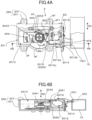
FIG. 4A is a plan view illustrating airflow in the optical scanning apparatus and the air duct. -
FIG. 4B is a cross-sectional view taken along a 4B-4B line ofFIG. 4A . - A
printer 1 of the present embodiment, which serves as an image forming apparatus, is an electrophotographic laser-beam printer. As illustrated inFIG. 1 , theprinter 1 includes asheet stacking portion 21, animage forming portion 30, afixing apparatus 8, and adischarging roller pair 9. Thesheet stacking portion 21 is disposed in a lower portion of aprinter body 1A, and theimage forming portion 30 forms an image on a sheet P fed from thesheet stacking portion 21. - When an image forming instruction is sent to the
printer 1, theimage forming portion 30 starts an image forming process in accordance with image information sent from, for example, an external computer connected to theprinter 1. Theimage forming portion 30 includes aprocess cartridge 3, anoptical scanning apparatus 2, and atransfer roller 7. Theprocess cartridge 3 includes aphotosensitive drum 4 that serves as an image bearing member, acharging roller 3a, and a developingroller 3b. Theoptical scanning apparatus 2 emits a laser beam L toward thephotosensitive drum 4, in accordance with the image information sent from the external computer. Thephotosensitive drum 4 is charged in advance by thecharging roller 3a. Thus, by the laser beam L emitted to thephotosensitive drum 4, an electrostatic latent image is formed on thephotosensitive drum 4. After that, the electrostatic latent image is developed by the developingroller 3b, so that a toner image is formed on thephotosensitive drum 4. - In parallel with the above-described image forming process, a sheet P stacked on the
sheet stacking portion 21 is fed by afeeding roller 5. Note that the sheet P is separated from other sheets, one by one, by a separation portion (not illustrated). The sheet P is then conveyed by an intermediateconveyance roller pair 6, toward thetransfer roller 7. Thetransfer roller 7 is applied with transfer bias, and transfers the toner image formed on thephotosensitive drum 4, onto the sheet P. - The sheet P onto which the toner image has been transferred by the
transfer roller 7 is heated and pressed by thefixing apparatus 8, so that the toner image is fixed to the sheet P. The sheet P is then discharged to adischarging tray 22 by thedischarging roller pair 9. - In the present embodiment, the
process cartridge 3 includes thephotosensitive drum 4, thecharging roller 3a, and the developingroller 3b. However, the present disclosure is not limited to this. For example, theprocess cartridge 3 may include a drum cartridge that includes thephotosensitive drum 4 and thecharging roller 3a, and a developing cartridge that includes the developingroller 3b. In this case, the developing cartridge is detachably attached to the drum cartridge. The sheet may be a paper sheet, such as a sheet for any purpose or an envelope, a plastic film such as an overhead projector (OHP) sheet, or a cloth sheet. - Next, a configuration of the
optical scanning apparatus 2 will be described with reference toFIGS. 2 to 3B .FIG. 2 is a perspective view illustrating theoptical scanning apparatus 2 and anair duct 10.FIG. 3A is a plan view illustrating theoptical scanning apparatus 2 and theair duct 10.FIG. 3B is a cross-sectional view taken along a 3B-3B line ofFIG. 3A . Note that inFIGS. 2 and3A , part of acover portion 207 is cut out for illustrating the interior of acasing 250 of theoptical scanning apparatus 2. In practice, however, theoptical scanning apparatus 2 is sealed by thecasing 250. - As illustrated in
FIG. 2 , theoptical scanning apparatus 2 includes a laser light-source unit 202 that serves as a light source, animage forming lens 203 that serves as an optical element, alight deflector 204, ascanning lens 205, thecasing 250, and alaser board 206. The laser light-source unit 202, theimage forming lens 203, thelight deflector 204, and thescanning lens 205 are accommodated in thecasing 250, and supported by abase portion 201 of thecasing 250. Thecasing 250 includes thebase portion 201 and thecover portion 207. Thebase portion 201 is formed like a box, and one portion of thebase portion 201 is opened. Thecover portion 207 covers the opening portion of thebase portion 201. - The
laser board 206 is supported by thebase portion 201 in the outside of thecasing 250. Thelight deflector 204 includes apolygon mirror 2041, a driving portion (not illustrated), and anintegrated circuit 2043. Thepolygon mirror 2041 is supported by arotary shaft 2042 such that thepolygon mirror 2041 can rotate around therotary shaft 2042. The driving portion includes a motor that rotates thepolygon mirror 2041. Theintegrated circuit 2043 controls the driving portion. Thepolygon mirror 2041 includes a plurality of reflectingsurfaces 2041a configured to reflect light emitted from the laser light-source unit 202. - The
laser board 206 causes the laser light-source unit 202 to emit a laser beam in accordance with the image information sent from the external computer. The laser beam emitted from the laser light-source unit 202 is imaged on thepolygon mirror 2041 of thelight deflector 204 by theimage forming lens 203. Thepolygon mirror 2041 is rotated on therotary shaft 2042 in a direction indicated by an arrow RD inFIGS. 2 and3A , by the driving portion (not illustrated). With this rotation, the laser beam is deflected by thepolygon mirror 2041, and thephotosensitive drum 4 is scanned with the deflected laser beam by thepolygon mirror 2041. The laser beam passes through thescanning lens 205, and forms an electrostatic latent image on the photosensitive drum 4 (seeFIG. 1 ). - As illustrated in
FIG. 3A , thebase portion 201 of theoptical scanning apparatus 2 includes four fixingportions fixing portions printer body 1A (seeFIG. 1 ) of theprinter 1, via screws. Theair duct 10 is disposed in the vicinity of theoptical scanning apparatus 2 of theprinter 1, and forms a wind channel through which cooling wind is conveyed to theoptical scanning apparatus 2. The cooling wind is taken in from the outside of theprinter 1 by an air blowing fan (not illustrated). The air that has passed through theair duct 10 is emitted from anair outlet 1001 disposed in theair duct 10, to theoptical scanning apparatus 2. - Next, a configuration of the
base portion 201 of theoptical scanning apparatus 2 will be described with reference toFIGS. 3A and 3B . Thebase portion 201 includes a first wall-surface group 2011 and a second wall-surface group 2012. The first wall-surface group 2011 surrounds thelight deflector 204, and the second wall-surface group 2012 is formed continuously with the first wall-surface group 2011 via apartition wall 2050. The first wall-surface group 2011 includeswall surfaces first space 2013. That is, thelight deflector 204 is accommodated in thefirst space 2013. - The second wall-
surface group 2012 includeswall surfaces second space 2014 that is different from thefirst space 2013. Thepartition wall 2050 is disposed between thefirst space 2013 and thesecond space 2014, and defines a communicatingspace 2016 that causes thefirst space 2013 and thesecond space 2014 to communicate with each other. Thepartition wall 2050 includes thewall surface 2011e, which is a portion of the wall surfaces that define thefirst space 2013, and thewall surface 2012d, which is disposed opposite to thewall surface 2011e and is a portion of the wall surfaces that define thesecond space 2014. In thesecond space 2014, optical elements, such as the laser light-source unit 202 and theimage forming lens 203, are not disposed. - The
second space 2014 is disposed further from therotary shaft 2042 of thepolygon mirror 2041 than thepartition wall 2050 in a radial direction orthogonal to an axial direction AD of therotary shaft 2042, and is disposed such that thesecond space 2014 overlaps with thefirst space 2013 in the axial direction AD. In addition, thesecond space 2014 overlaps with the laser light-source unit 202 and theimage forming lens 203 in a laser emission direction ED of the laser light-source unit 202. In addition, thesecond space 2014 is arranged to be shifted from the laser light-source unit 202 and theimage forming lens 203 in an orthogonal direction OD orthogonal to the emission direction ED and the axial direction AD. In addition, thesecond space 2014 is disposed between the communicatingspace 2016 and thelaser board 206 in the emission direction ED. In other words, thesecond space 2014 is disposed between thepartition wall 2050 and thelaser board 206 in the emission direction ED. Thefirst space 2013 is arranged to be shifted from the laser light-source unit 202, theimage forming lens 203, and thesecond space 2014 in the emission direction ED. That is, thesecond space 2014 is provided in a dead space surrounded by thelaser board 206, the laser light-source unit 202, theimage forming lens 203, and the fixingportion 2020. Thus, thesecond space 2014 is defined in thecasing 250 so as not to upsize theoptical scanning apparatus 2. - In addition, the
second space 2014 is disposed downstream of the communicatingspace 2016 in the direction indicated by the arrow RD, which is the rotational direction of thepolygon mirror 2041, and at a position at which thesecond space 2014 faces theair outlet 1001 disposed in theair duct 10. - The
wall surface 2011d, which is a portion of the wall surfaces that defines thefirst space 2013, projects toward a direction separating from therotary shaft 2042 more than thewall surface 2011c is in a radial direction orthogonal to the axial direction AD. More specifically, thewall surface 2011d is formed in an arc shape around therotary shaft 2042, and projects toward a direction in which thewall surface 2011d is separated more from therotary shaft 2042 than the wall surfaces 2011c and 2012c are. Note that thewall surface 2011c serves as a first surface, extends in the emission direction ED and the axial direction AD, and defines a part of thefirst space 2013. Thewall surface 2011d serves as a second surface, and is formed continuously with the wall surfaces 2011c and 2012c and disposed upstream of thepartition wall 2050 in the direction indicated by the arrow RD. - Since the
wall surface 2011d is formed an arc shape in this manner, the capacity of thefirst space 2013 can be increased by using a space between the fixingportions casing 250 can be reduced. In addition, since thewall surface 2011d is formed in an arc shape, it is possible to reduce wind noise caused by the airflow, generated by thepolygon mirror 2041, abutting against thewall surface 2011d. - The
partition wall 2050 includes anopening portion 2051 formed in an upper portion of thepartition wall 2050. As illustrated inFIGS. 2 and3B , theopening portion 2051 is formed so that thepartition wall 2050 becomes lower in height than thewall surfaces opening portion 2051 is disposed between thefirst space 2013 and thesecond space 2014, and defines the communicatingspace 2016. The communicatingspace 2016 is disposed above thepolygon mirror 2041 and arranged to be shifted from thepolygon mirror 2041 in the axial direction AD. Thus, the airflow generated in the vicinity of thepolygon mirror 2041 and having high wind velocity mainly collides with thewall surface 2011e of thepartition wall 2050 in the first place. Since the airflow collides with thewall surface 2011e, the wind noise caused by the airflow passing through the communicatingspace 2016 and directly colliding with thewall surface 2012a can be reduced. - In the present embodiment, the whole of the communicating
space 2016 is arranged to be shifted from thepolygon mirror 2041 in the axial direction AD. However, the present disclosure is not limited to this. For example, the communicatingspace 2016 may be disposed at a position at which at least one portion of the communicatingspace 2016 is arranged to be shifted from thepolygon mirror 2041 in the axial direction AD. In another case, the communicatingspace 2016 may be disposed at a position at which the whole of the communicatingspace 2016 overlaps with thepolygon mirror 2041 in the axial direction AD. Airflow in Casing of Optical Scanning Apparatus - Next, the airflow in the
casing 250 of theoptical scanning apparatus 2 will be described with reference toFIGS. 4A and 4B . As illustrated inFIGS. 4A and 4B , when thepolygon mirror 2041 rotates in a direction indicated by the arrow RD, airflow AF is generated around thepolygon mirror 2041 in thecasing 250, along the direction indicated by the arrow RD. This is because thepolygon mirror 2041 agitates the air contained in thecasing 250, in the direction indicated by the arrow RD. - The air is heated by the heat generated by the
integrated circuit 2043 and a rotor bearing portion of thelight deflector 204, and rides the airflow AF and flows in thecasing 250. Part of the air, like airflow AF1, flows from thefirst space 2013 toward the communicatingspace 2016. After that, the airflow AF1 flows from the communicatingspace 2016 into thesecond space 2014, and convects in thesecond space 2014, along thecover portion 207 and thewall surfaces casing 250. - On the other hand, cooling wind AF2 emitted from the
air outlet 1001 of theair duct 10 is blown toward thesecond space 2014 of thecasing 250. That is, theair outlet 1001 is an air blowing portion that blows air toward an outer wall of thecasing 250, which defines thesecond space 2014. Theair outlet 1001 is disposed opposite to thefirst space 2013 with respect to the laser light-source unit 202, theimage forming lens 203, and thesecond space 2014 in the emission direction ED. After the cooling wind AF2 collides with thecasing 250, part of the cooling wind AF2 flows on the outer surfaces of the second wall-surface group 2012 and thecover portion 207 that surround thesecond space 2014. - A portion of the second wall-
surface group 2012, which defines thesecond space 2014, is formed by the outer wall of thecasing 250. More specifically, at least the wall surfaces 2012b and 2012c of the second wall-surface group 2012 are formed by the outer wall of thecasing 250. Thus, the air in thesecond space 2014, which is heated by the airflow AF1 that flows from thefirst space 2013 into thesecond space 2014, is cooled by the cooling wind AF2 that flows along the outer surface of thecasing 250 in a state where the cooling wind AF2 is in contact with the outer surface. Then, the air cooled in thesecond space 2014 flows out into thefirst space 2013 through the communicatingspace 2016. By repeating the above-described cycle, the air heated in thecasing 250 can be cooled efficiently, and the temperature rise in thecasing 250 can be reduced. - As described above, in the present embodiment, the
second space 2014 defined by the second wall-surface group 2012 is provided in a dead space of thecasing 250. In addition, thefirst space 2013, in which thelight deflector 204 is disposed, and thesecond space 2014 communicate with each other via the communicatingspace 2016, and thefirst space 2013 and thesecond space 2014 are disposed at positions at which thefirst space 2013 and thesecond space 2014 overlap with each other in the axial direction AD. - Since the
casing 250 of theoptical scanning apparatus 2 is configured simply in this manner, the increase in cost and size can be prevented. In addition, part of the air heated in thefirst space 2013, in which thelight deflector 204 is disposed, rides the airflow and flows into thesecond space 2014. Then, the air is cooled in thesecond space 2014, and returns to thefirst space 2013. With this operation, the cooling performance of theoptical scanning apparatus 2 can be increased. That is, it is possible to provide theoptical scanning apparatus 2 whose cooling performance is increased while the increase in cost and size is prevented. Since the cooling performance of theoptical scanning apparatus 2 is increased, the print precision on thephotosensitive drum 4 is increased, which increases the image quality. - In addition, since the communicating
space 2016 is arranged to be shifted from thepolygon mirror 2041 in the axial direction AD, the wind noise, caused by the airflow generated by thepolygon mirror 2041, can be reduced. A part of the walls that define thesecond space 2014 is the outer wall of thecasing 250, and the cooling wind AF2 from theair duct 10 is blown toward the outer wall. As a result, the air in thesecond space 2014 can be cooled efficiently. Thus, the cooling performance of theoptical scanning apparatus 2 can be increased. - In the present embodiment, the
polygon mirror 2041 rotates counterclockwise in the rotational direction (indicated by the arrow RD). However, the present disclosure is not limited to this. For example, thepolygon mirror 2041 may rotate clockwise. In this case, the same effects as those of the present embodiment can be produced if thesecond space 2014 is arranged downstream of the communicatingspace 2016 in the rotational direction of thepolygon mirror 2041. - In the present embodiment, the communicating
space 2016 is defined by theopening portion 2051 of thepartition wall 2050. However, the present disclosure is not limited to this. For example, a through-hole portion may be formed in thepartition wall 2050, and the internal space of the through-hole portion may serve as the communicatingspace 2016. - In the present embodiment, the communicating
space 2016 is disposed at a position that is higher than thepolygon mirror 2041 in the axial direction AD. However, the present disclosure is not limited to this. For example, the communicatingspace 2016 may be disposed at a position that is lower than thepolygon mirror 2041 in the axial direction AD. That is, the communicatingspace 2016 has only to be disposed so as not to overlap with thepolygon mirror 2041. - In the present embodiment, the
optical scanning apparatus 2 is configured such that a portion of thecasing 250, especially a portion that defines thesecond space 2014, is cooled by the cooling wind AF2 from theair duct 10. However, the present disclosure is not limited to this. For example, the cooling wind AF2 may be blown on another portion of thecasing 250 or on an area near thecasing 250 as long as thesecond space 2014 can be cooled. In another case, theair duct 10 may not be used, and the airflow generated by a fan may be directly blown on thecasing 250. Furthermore, thecasing 250 may be cooled not by the cooling wind, but by a heatsink or the like. - In the present embodiment, the laser light-
source unit 202 is used as the light source of theoptical scanning apparatus 2. However, the present disclosure is not limited to this. For example, another light source, such as an incandescent lamp, a halogen lamp, a fluorescent lamp, or a light emitting diode, may be used. - In the present embodiment, the
image forming lens 203 is disposed in thecasing 250. However, the present disclosure is not limited to this. For example, theimage forming lens 203 may not be disposed, and the light emitted from the laser light-source unit 202 may be reflected by thepolygon mirror 2041, without passing through theimage forming lens 203. - The present embodiment has been described for the
electrophotographic printer 1, but the present invention is not limited to this. For example, the present invention may also be applied to an ink-jet image forming apparatus that forms images on sheets by injecting ink from a nozzle. - While the present invention has been described with reference to exemplary embodiments, it is to be understood that the invention is not limited to the disclosed exemplary embodiments. The scope of the following claims is to be accorded the broadest interpretation so as to encompass all such modifications and equivalent structures and functions.
An optical scanning apparatus (2) includes a light source (202), a polygon mirror (2041) being configured to be rotated around a rotary shaft (2042), and a casing (250) configured to accommodate the light source (202) and the polygon mirror (2041). The casing (250) defines a first space (2013) that accommodates the polygon mirror (2041) and a second space (2014) that is different from the first space (2013), the casing (250) including a partition wall (2050) disposed between the first space (2013) and the second space (2014). The second space (2014) is disposed further from the rotary shaft (2042) than the partition wall (2050) in a radial direction orthogonal to an axial direction (AD) of the rotary shaft (2042), and is disposed such that the second space (2014) overlaps with the first space (2013) in the axial direction (AD).
Claims (14)
- An optical scanning apparatus (2) comprising:a light source (202);a polygon mirror (2041) including a plurality of reflecting surfaces (2041a) configured to reflect light emitted from the light source (202), the polygon mirror (2041) being configured to be rotated around a rotary shaft (2042); anda casing (250) configured to accommodate the light source (202) and the polygon mirror (2041),wherein the casing (250) defines a first space (2013) that accommodates the polygon mirror (2041) and a second space (2014) that is different from the first space (2013), the casing (250) including a partition wall (2050) disposed between the first space (2013) and the second space (2014), andwherein the second space (2014) is disposed further from the rotary shaft (2042) than the partition wall (2050) in a radial direction orthogonal to an axial direction (AD) of the rotary shaft (2042), and is disposed such that the second space (2014) overlaps with the first space (2013) in the axial direction (AD).
- The optical scanning apparatus (2) according to claim 1, wherein the partition wall (2050) defines a communicating space (2016) configured to communicate the first space (2013) and the second space (2014) with each other.
- The optical scanning apparatus (2) according to claim 2, wherein at least a portion of the communicating space (2016) is arranged to be shifted from the polygon mirror (2041) in the axial direction (AD).
- The optical scanning apparatus (2) according to claim 2, wherein a whole of the communicating space (2016) is arranged to be shifted from the polygon mirror (2041) in the axial direction (AD).
- The optical scanning apparatus (2) according to any one of claims 1 through 4, wherein at least a part of walls that define the second space (2014) is an outer wall of the casing (250).
- The optical scanning apparatus (2) according to any one of claims 1 through 5, wherein the casing (250) includes:a first surface (2011c) configured to define a portion of the first space (2013), the first surface (2011c) extending in an emission direction (ED) in which the light source (202) emits the light and extending in the axial direction (AD); anda second surface (2011d) configured to be formed continuously with the first surface (2011c), and define a portion of the first space (2013), the second surface (2011d) projecting toward a direction separating from the rotary shaft (2042) in the radial direction more than the first surface (2011c), andwherein the second surface (2011d) is disposed upstream of the partition wall (2050) in a rotational direction of the rotary shaft (2042).
- The optical scanning apparatus (2) according to claim 6, wherein the second surface (2011d) is formed in an arc shape around the rotary shaft (2042).
- The optical scanning apparatus (2) according to any one of claims 1 through 7, further comprising an optical element (203) configured to image the light emitted from the light source (202) on the polygon mirror (2041).
- The optical scanning apparatus (2) according to claim 8, wherein the optical element (203) is not disposed in the second space (2014).
- The optical scanning apparatus (2) according to claim 8 or 9, wherein the second space (2014) overlaps with the light source (202) and the optical element (203) in an emission direction (ED) in which the light source (202) emits the light, and is arranged to be shifted from the light source (202) and the optical element (203) in an orthogonal direction, the orthogonal direction being orthogonal to the emission direction (ED) and the axial direction (AD).
- The optical scanning apparatus (2) according to claim 10, wherein the partition wall (2050) extends in the orthogonal direction, and
wherein the first space (2013) is shifted from the light source (202), the optical element (203), and the second space (2014) in the emission direction (ED). - An image forming apparatus comprising:the optical scanning apparatus (2) according to any one of claims 1 through 11;an image bearing member (4) on which an electrostatic latent image is formed by being scanned by the optical scanning apparatus (2); andan air blowing portion (1001) configured to blow air toward an outer wall of the casing (250), the outer wall being configured to define the second space (2014).
- The image forming apparatus according to claim 12, wherein the air blowing portion (1001) is disposed opposite to the first space (2013) with respect to the light source (202) and the second space (2014) in an emission direction (ED) in which the light source (202) emits the light.
- The image forming apparatus according to claim 12 or 13, wherein the light source (202) is a laser light-source unit (202) configured to emit a laser beam,wherein the optical scanning apparatus (2) includes a laser board (206) configured to control the laser light-source unit (202), andwherein the second space (2014) is disposed between the partition wall (2050) and the laser board (206) in an emission direction (ED) in which the light source (202) emits the light.
Applications Claiming Priority (1)
| Application Number | Priority Date | Filing Date | Title |
|---|---|---|---|
| JP2022125218A JP2024021978A (en) | 2022-08-05 | 2022-08-05 | Optical scanning device and image forming device |
Publications (2)
| Publication Number | Publication Date |
|---|---|
| EP4318076A1 true EP4318076A1 (en) | 2024-02-07 |
| EP4318076B1 EP4318076B1 (en) | 2025-10-08 |
Family
ID=87554907
Family Applications (1)
| Application Number | Title | Priority Date | Filing Date |
|---|---|---|---|
| EP23189209.2A Active EP4318076B1 (en) | 2022-08-05 | 2023-08-02 | Optical scanning apparatus and image forming apparatus |
Country Status (4)
| Country | Link |
|---|---|
| US (1) | US12372894B2 (en) |
| EP (1) | EP4318076B1 (en) |
| JP (1) | JP2024021978A (en) |
| CN (1) | CN117527982A (en) |
Citations (4)
| Publication number | Priority date | Publication date | Assignee | Title |
|---|---|---|---|---|
| US20060086494A1 (en) * | 2004-10-23 | 2006-04-27 | Samsung Electronics Co., Ltd. | System using radiation of far infrared ray for heat release |
| US20100091083A1 (en) * | 2008-10-10 | 2010-04-15 | Yukio Itami | Optical scanning device and image forming apparatus |
| JP2014016646A (en) | 2013-09-30 | 2014-01-30 | Kyocera Document Solutions Inc | Optical scanner and image forming apparatus including the same |
| JP2015200852A (en) | 2014-04-10 | 2015-11-12 | 京セラドキュメントソリューションズ株式会社 | Optical scanner, and image forming apparatus including optical scanner |
Family Cites Families (6)
| Publication number | Priority date | Publication date | Assignee | Title |
|---|---|---|---|---|
| JP5038239B2 (en) * | 2008-06-30 | 2012-10-03 | 株式会社リコー | Optical scanning apparatus and image forming apparatus |
| JP5247371B2 (en) * | 2008-11-19 | 2013-07-24 | キヤノン株式会社 | Scanning optical device and image forming apparatus having the same |
| JP2013011793A (en) * | 2011-06-30 | 2013-01-17 | Canon Inc | Optical scanner and electrophotographic image forming apparatus |
| JP7056170B2 (en) * | 2018-01-25 | 2022-04-19 | コニカミノルタ株式会社 | Optical scanning device and image forming device |
| JP2019191356A (en) * | 2018-04-25 | 2019-10-31 | キヤノン株式会社 | Optical scanner and image formation device |
| JP7391566B2 (en) * | 2019-08-09 | 2023-12-05 | キヤノン株式会社 | Optical scanning device and image forming device using the same |
-
2022
- 2022-08-05 JP JP2022125218A patent/JP2024021978A/en active Pending
-
2023
- 2023-07-26 US US18/359,102 patent/US12372894B2/en active Active
- 2023-08-01 CN CN202310956363.1A patent/CN117527982A/en active Pending
- 2023-08-02 EP EP23189209.2A patent/EP4318076B1/en active Active
Patent Citations (4)
| Publication number | Priority date | Publication date | Assignee | Title |
|---|---|---|---|---|
| US20060086494A1 (en) * | 2004-10-23 | 2006-04-27 | Samsung Electronics Co., Ltd. | System using radiation of far infrared ray for heat release |
| US20100091083A1 (en) * | 2008-10-10 | 2010-04-15 | Yukio Itami | Optical scanning device and image forming apparatus |
| JP2014016646A (en) | 2013-09-30 | 2014-01-30 | Kyocera Document Solutions Inc | Optical scanner and image forming apparatus including the same |
| JP2015200852A (en) | 2014-04-10 | 2015-11-12 | 京セラドキュメントソリューションズ株式会社 | Optical scanner, and image forming apparatus including optical scanner |
Also Published As
| Publication number | Publication date |
|---|---|
| US12372894B2 (en) | 2025-07-29 |
| JP2024021978A (en) | 2024-02-16 |
| CN117527982A (en) | 2024-02-06 |
| US20240045355A1 (en) | 2024-02-08 |
| EP4318076B1 (en) | 2025-10-08 |
Similar Documents
| Publication | Publication Date | Title |
|---|---|---|
| US8144180B2 (en) | Optical scanning apparatus and image forming apparatus including the same | |
| US11086248B2 (en) | Image forming apparatus with fan configured for dust-resistant cooling of optical scanning unit | |
| EP4318076B1 (en) | Optical scanning apparatus and image forming apparatus | |
| US9285769B2 (en) | Image forming apparatus including a duct for airflow having a sectional area that becomes gradually smaller toward a part of a rotating shaft exposed into the duct | |
| JP4398289B2 (en) | Optical writing apparatus and image forming apparatus | |
| US10382641B2 (en) | Optical scanning device that directs heat away from a deflector and image forming device including same | |
| US10425550B2 (en) | Optical scanning device with duct for heat dissipation, and image forming device having the same | |
| JPH1152267A (en) | Optical deflection scanning device and image forming apparatus equipped with the same | |
| JP2006178166A (en) | Image forming apparatus | |
| JP5589456B2 (en) | Image forming apparatus | |
| JP6170461B2 (en) | Optical scanning device and image forming apparatus including the optical scanning device | |
| CN223598125U (en) | Image forming apparatus having a plurality of image forming units | |
| JP2004361826A (en) | Cooling device and image forming device | |
| JP6493528B2 (en) | Optical scanning apparatus and image forming apparatus | |
| JP5297597B2 (en) | Scanning optical device and image forming apparatus equipped with the same | |
| JP5401140B2 (en) | Optical scanning apparatus and image forming apparatus | |
| JP2011137941A (en) | Optical scanning apparatus and image forming apparatus | |
| JPH07191593A (en) | Image recorder | |
| JP5016365B2 (en) | Scanning optical device and image forming apparatus equipped with the same | |
| JPH09216415A (en) | Image forming device | |
| JP2006201441A (en) | Image forming apparatus | |
| JP6600768B2 (en) | Scanning optical apparatus and image forming apparatus | |
| JP2024001407A (en) | Image formation apparatus | |
| JP2024033971A (en) | Image forming device | |
| JP2000194250A (en) | Image forming device |
Legal Events
| Date | Code | Title | Description |
|---|---|---|---|
| PUAI | Public reference made under article 153(3) epc to a published international application that has entered the european phase |
Free format text: ORIGINAL CODE: 0009012 |
|
| STAA | Information on the status of an ep patent application or granted ep patent |
Free format text: STATUS: THE APPLICATION HAS BEEN PUBLISHED |
|
| AK | Designated contracting states |
Kind code of ref document: A1 Designated state(s): AL AT BE BG CH CY CZ DE DK EE ES FI FR GB GR HR HU IE IS IT LI LT LU LV MC ME MK MT NL NO PL PT RO RS SE SI SK SM TR |
|
| STAA | Information on the status of an ep patent application or granted ep patent |
Free format text: STATUS: REQUEST FOR EXAMINATION WAS MADE |
|
| 17P | Request for examination filed |
Effective date: 20240807 |
|
| RBV | Designated contracting states (corrected) |
Designated state(s): AL AT BE BG CH CY CZ DE DK EE ES FI FR GB GR HR HU IE IS IT LI LT LU LV MC ME MK MT NL NO PL PT RO RS SE SI SK SM TR |
|
| GRAP | Despatch of communication of intention to grant a patent |
Free format text: ORIGINAL CODE: EPIDOSNIGR1 |
|
| STAA | Information on the status of an ep patent application or granted ep patent |
Free format text: STATUS: GRANT OF PATENT IS INTENDED |
|
| INTG | Intention to grant announced |
Effective date: 20250321 |
|
| GRAS | Grant fee paid |
Free format text: ORIGINAL CODE: EPIDOSNIGR3 |
|
| GRAA | (expected) grant |
Free format text: ORIGINAL CODE: 0009210 |
|
| STAA | Information on the status of an ep patent application or granted ep patent |
Free format text: STATUS: THE PATENT HAS BEEN GRANTED |
|
| AK | Designated contracting states |
Kind code of ref document: B1 Designated state(s): AL AT BE BG CH CY CZ DE DK EE ES FI FR GB GR HR HU IE IS IT LI LT LU LV MC ME MK MT NL NO PL PT RO RS SE SI SK SM TR |
|
| REG | Reference to a national code |
Ref country code: GB Ref legal event code: FG4D Ref country code: CH Ref legal event code: F10 Free format text: ST27 STATUS EVENT CODE: U-0-0-F10-F00 (AS PROVIDED BY THE NATIONAL OFFICE) Effective date: 20251008 |
|
| REG | Reference to a national code |
Ref country code: DE Ref legal event code: R096 Ref document number: 602023007264 Country of ref document: DE |
|
| REG | Reference to a national code |
Ref country code: IE Ref legal event code: FG4D |
|
| REG | Reference to a national code |
Ref country code: NL Ref legal event code: MP Effective date: 20251008 |
|
| REG | Reference to a national code |
Ref country code: AT Ref legal event code: MK05 Ref document number: 1845284 Country of ref document: AT Kind code of ref document: T Effective date: 20251008 |
|
| PG25 | Lapsed in a contracting state [announced via postgrant information from national office to epo] |
Ref country code: NL Free format text: LAPSE BECAUSE OF FAILURE TO SUBMIT A TRANSLATION OF THE DESCRIPTION OR TO PAY THE FEE WITHIN THE PRESCRIBED TIME-LIMIT Effective date: 20251008 |
|
| PG25 | Lapsed in a contracting state [announced via postgrant information from national office to epo] |
Ref country code: ES Free format text: LAPSE BECAUSE OF FAILURE TO SUBMIT A TRANSLATION OF THE DESCRIPTION OR TO PAY THE FEE WITHIN THE PRESCRIBED TIME-LIMIT Effective date: 20251008 |
|
| REG | Reference to a national code |
Ref country code: LT Ref legal event code: MG9D |
|
| PG25 | Lapsed in a contracting state [announced via postgrant information from national office to epo] |
Ref country code: NO Free format text: LAPSE BECAUSE OF FAILURE TO SUBMIT A TRANSLATION OF THE DESCRIPTION OR TO PAY THE FEE WITHIN THE PRESCRIBED TIME-LIMIT Effective date: 20260108 |
|
| PG25 | Lapsed in a contracting state [announced via postgrant information from national office to epo] |
Ref country code: AT Free format text: LAPSE BECAUSE OF FAILURE TO SUBMIT A TRANSLATION OF THE DESCRIPTION OR TO PAY THE FEE WITHIN THE PRESCRIBED TIME-LIMIT Effective date: 20251008 Ref country code: FI Free format text: LAPSE BECAUSE OF FAILURE TO SUBMIT A TRANSLATION OF THE DESCRIPTION OR TO PAY THE FEE WITHIN THE PRESCRIBED TIME-LIMIT Effective date: 20251008 Ref country code: HR Free format text: LAPSE BECAUSE OF FAILURE TO SUBMIT A TRANSLATION OF THE DESCRIPTION OR TO PAY THE FEE WITHIN THE PRESCRIBED TIME-LIMIT Effective date: 20251008 |
|
| PG25 | Lapsed in a contracting state [announced via postgrant information from national office to epo] |
Ref country code: RS Free format text: LAPSE BECAUSE OF FAILURE TO SUBMIT A TRANSLATION OF THE DESCRIPTION OR TO PAY THE FEE WITHIN THE PRESCRIBED TIME-LIMIT Effective date: 20260108 |
|
| PG25 | Lapsed in a contracting state [announced via postgrant information from national office to epo] |
Ref country code: IS Free format text: LAPSE BECAUSE OF FAILURE TO SUBMIT A TRANSLATION OF THE DESCRIPTION OR TO PAY THE FEE WITHIN THE PRESCRIBED TIME-LIMIT Effective date: 20260208 |
|
| PG25 | Lapsed in a contracting state [announced via postgrant information from national office to epo] |
Ref country code: PT Free format text: LAPSE BECAUSE OF FAILURE TO SUBMIT A TRANSLATION OF THE DESCRIPTION OR TO PAY THE FEE WITHIN THE PRESCRIBED TIME-LIMIT Effective date: 20260209 |
|
| PG25 | Lapsed in a contracting state [announced via postgrant information from national office to epo] |
Ref country code: PL Free format text: LAPSE BECAUSE OF FAILURE TO SUBMIT A TRANSLATION OF THE DESCRIPTION OR TO PAY THE FEE WITHIN THE PRESCRIBED TIME-LIMIT Effective date: 20251008 |
|
| PG25 | Lapsed in a contracting state [announced via postgrant information from national office to epo] |
Ref country code: LV Free format text: LAPSE BECAUSE OF FAILURE TO SUBMIT A TRANSLATION OF THE DESCRIPTION OR TO PAY THE FEE WITHIN THE PRESCRIBED TIME-LIMIT Effective date: 20251008 |
|
| PG25 | Lapsed in a contracting state [announced via postgrant information from national office to epo] |
Ref country code: BG Free format text: LAPSE BECAUSE OF FAILURE TO SUBMIT A TRANSLATION OF THE DESCRIPTION OR TO PAY THE FEE WITHIN THE PRESCRIBED TIME-LIMIT Effective date: 20251008 |