EP4318021A1 - Electronic device - Google Patents
Electronic device Download PDFInfo
- Publication number
- EP4318021A1 EP4318021A1 EP22775244.1A EP22775244A EP4318021A1 EP 4318021 A1 EP4318021 A1 EP 4318021A1 EP 22775244 A EP22775244 A EP 22775244A EP 4318021 A1 EP4318021 A1 EP 4318021A1
- Authority
- EP
- European Patent Office
- Prior art keywords
- transmission
- antennas
- reception
- electronic device
- signals
- Prior art date
- Legal status (The legal status is an assumption and is not a legal conclusion. Google has not performed a legal analysis and makes no representation as to the accuracy of the status listed.)
- Pending
Links
- 230000005540 biological transmission Effects 0.000 claims abstract description 401
- 238000012545 processing Methods 0.000 description 65
- 230000010363 phase shift Effects 0.000 description 21
- 230000006870 function Effects 0.000 description 20
- 238000010586 diagram Methods 0.000 description 18
- 238000006243 chemical reaction Methods 0.000 description 15
- 238000005516 engineering process Methods 0.000 description 13
- 239000000758 substrate Substances 0.000 description 13
- 238000000034 method Methods 0.000 description 9
- 238000001514 detection method Methods 0.000 description 8
- 238000004891 communication Methods 0.000 description 4
- 238000012937 correction Methods 0.000 description 4
- 230000000052 comparative effect Effects 0.000 description 2
- 230000001934 delay Effects 0.000 description 2
- 230000000694 effects Effects 0.000 description 2
- 238000009434 installation Methods 0.000 description 2
- 239000000463 material Substances 0.000 description 2
- 229920003051 synthetic elastomer Polymers 0.000 description 2
- 229920003002 synthetic resin Polymers 0.000 description 2
- 239000000057 synthetic resin Substances 0.000 description 2
- 239000005061 synthetic rubber Substances 0.000 description 2
- 239000013598 vector Substances 0.000 description 2
- 241000238631 Hexapoda Species 0.000 description 1
- 241001465754 Metazoa Species 0.000 description 1
- 230000003247 decreasing effect Effects 0.000 description 1
- 230000002708 enhancing effect Effects 0.000 description 1
- 238000003384 imaging method Methods 0.000 description 1
- 238000005259 measurement Methods 0.000 description 1
- 230000003287 optical effect Effects 0.000 description 1
- 230000005855 radiation Effects 0.000 description 1
- 239000004065 semiconductor Substances 0.000 description 1
- 230000002123 temporal effect Effects 0.000 description 1
Images




Classifications
-
- G—PHYSICS
- G01—MEASURING; TESTING
- G01S—RADIO DIRECTION-FINDING; RADIO NAVIGATION; DETERMINING DISTANCE OR VELOCITY BY USE OF RADIO WAVES; LOCATING OR PRESENCE-DETECTING BY USE OF THE REFLECTION OR RERADIATION OF RADIO WAVES; ANALOGOUS ARRANGEMENTS USING OTHER WAVES
- G01S7/00—Details of systems according to groups G01S13/00, G01S15/00, G01S17/00
- G01S7/02—Details of systems according to groups G01S13/00, G01S15/00, G01S17/00 of systems according to group G01S13/00
- G01S7/03—Details of HF subsystems specially adapted therefor, e.g. common to transmitter and receiver
- G01S7/032—Constructional details for solid-state radar subsystems
-
- G—PHYSICS
- G01—MEASURING; TESTING
- G01S—RADIO DIRECTION-FINDING; RADIO NAVIGATION; DETERMINING DISTANCE OR VELOCITY BY USE OF RADIO WAVES; LOCATING OR PRESENCE-DETECTING BY USE OF THE REFLECTION OR RERADIATION OF RADIO WAVES; ANALOGOUS ARRANGEMENTS USING OTHER WAVES
- G01S13/00—Systems using the reflection or reradiation of radio waves, e.g. radar systems; Analogous systems using reflection or reradiation of waves whose nature or wavelength is irrelevant or unspecified
- G01S13/88—Radar or analogous systems specially adapted for specific applications
- G01S13/93—Radar or analogous systems specially adapted for specific applications for anti-collision purposes
- G01S13/931—Radar or analogous systems specially adapted for specific applications for anti-collision purposes of land vehicles
-
- G—PHYSICS
- G01—MEASURING; TESTING
- G01S—RADIO DIRECTION-FINDING; RADIO NAVIGATION; DETERMINING DISTANCE OR VELOCITY BY USE OF RADIO WAVES; LOCATING OR PRESENCE-DETECTING BY USE OF THE REFLECTION OR RERADIATION OF RADIO WAVES; ANALOGOUS ARRANGEMENTS USING OTHER WAVES
- G01S7/00—Details of systems according to groups G01S13/00, G01S15/00, G01S17/00
- G01S7/02—Details of systems according to groups G01S13/00, G01S15/00, G01S17/00 of systems according to group G01S13/00
- G01S7/03—Details of HF subsystems specially adapted therefor, e.g. common to transmitter and receiver
-
- H—ELECTRICITY
- H01—ELECTRIC ELEMENTS
- H01Q—ANTENNAS, i.e. RADIO AERIALS
- H01Q1/00—Details of, or arrangements associated with, antennas
- H01Q1/27—Adaptation for use in or on movable bodies
- H01Q1/32—Adaptation for use in or on road or rail vehicles
- H01Q1/3208—Adaptation for use in or on road or rail vehicles characterised by the application wherein the antenna is used
- H01Q1/3233—Adaptation for use in or on road or rail vehicles characterised by the application wherein the antenna is used particular used as part of a sensor or in a security system, e.g. for automotive radar, navigation systems
-
- H—ELECTRICITY
- H01—ELECTRIC ELEMENTS
- H01Q—ANTENNAS, i.e. RADIO AERIALS
- H01Q13/00—Waveguide horns or mouths; Slot antennas; Leaky-waveguide antennas; Equivalent structures causing radiation along the transmission path of a guided wave
- H01Q13/20—Non-resonant leaky-waveguide or transmission-line antennas; Equivalent structures causing radiation along the transmission path of a guided wave
- H01Q13/206—Microstrip transmission line antennas
-
- H—ELECTRICITY
- H01—ELECTRIC ELEMENTS
- H01Q—ANTENNAS, i.e. RADIO AERIALS
- H01Q21/00—Antenna arrays or systems
- H01Q21/06—Arrays of individually energised antenna units similarly polarised and spaced apart
- H01Q21/061—Two dimensional planar arrays
- H01Q21/065—Patch antenna array
-
- G—PHYSICS
- G01—MEASURING; TESTING
- G01S—RADIO DIRECTION-FINDING; RADIO NAVIGATION; DETERMINING DISTANCE OR VELOCITY BY USE OF RADIO WAVES; LOCATING OR PRESENCE-DETECTING BY USE OF THE REFLECTION OR RERADIATION OF RADIO WAVES; ANALOGOUS ARRANGEMENTS USING OTHER WAVES
- G01S7/00—Details of systems according to groups G01S13/00, G01S15/00, G01S17/00
- G01S7/02—Details of systems according to groups G01S13/00, G01S15/00, G01S17/00 of systems according to group G01S13/00
- G01S7/35—Details of non-pulse systems
- G01S7/352—Receivers
- G01S7/356—Receivers involving particularities of FFT processing
Definitions
- the present disclosure relates to an electronic device.
- a technology for measuring a distance or the like between a vehicle of interest and a predetermined object is regarded as important.
- various studies have been conducted particularly on a radar (Radio Detecting and Ranging) technology for measuring a distance or the like to an object such as an obstacle by transmitting a radio wave such as a millimeter wave and receiving a reflected wave reflected off the object.
- a radar Radio Detecting and Ranging
- Such a technology for measuring a distance or the like expectedly becomes more important in the future with progresses of a technology for assisting drivers in driving and an automated-driving-related technology for partially or entirely automating driving.
- Patent Literature 1 has proposed a millimeter-wave transmission/reception device in which multiple patch antennas are connected in parallel by transmission lines all having an equal length.
- Patent Literature 1 has also proposed a millimeter-wave transmission/reception device in which multiple sets of multiple patch antennas that are longitudinally arranged and are directly connected to each other by transmission lines each having an equal length are further arranged in a lateral direction. With such arrangements of the patch antennas, an effect of enhancing the directivity of transmission waves in a front direction can be expected.
- Patent Literature 2 has proposed a radar device in which patch antennas are connected at an interval of n ⁇ (where n denotes an integer of 2 or greater and ⁇ denotes a wavelength of a center frequency to be used). With such an arrangement of the patch antennas, a tilt angle in a vertical direction is increased at a frequency shifted from the center frequency, and an effect of adjusting a radiation direction of a radar wave by utilizing the change in the tilt angle can be expected.
- an electronic device in one embodiment, includes a plurality of transmission antennas, a plurality of reception antennas, and an electronic component.
- the plurality of transmission antennas is each configured to transmit a transmission wave.
- the plurality of reception antennas is each configured to receive a reflected wave that is the transmission wave having been reflected.
- the electronic component is configured to output respective transmission signals to the plurality of transmission antennas and receive respective reception signals from the plurality of reception antennas.
- the electronic component has a first edge where a plurality of transmission terminals each configured to output a respective one of the transmission signals to a respective one of the plurality of transmission antennas is arranged, and a second edge where a plurality of reception terminals each configured to receive a respective one of the reception signals from a respective one of the plurality of reception antennas is arranged.
- At least one of the first edge or the second edge is located obliquely relative to at least one of a direction in which respective feeding points of the plurality of transmission antennas are arranged or a direction in which respective feeding points of the plurality of reception antennas are arranged.
- a signal loss in transmission lines to antennas that transmit and receive signals for detecting the object is successfully reduced if the transmission lines are shortened.
- the present disclosure provides an electronic device that may allow shortened transmission lines to antennas that transmit and receive signals for detecting an object.
- One embodiment can provide an electronic device that may allow shortened transmission lines to antennas that transmit and receive signals for detecting an object.
- One embodiment is described in detail below with reference to the drawings.
- An electronic device is mounted in a vehicle (mobility device) such as an automobile, for example, and thus is capable of detecting a predetermined object located around the mobility device.
- the electronic device according to the one embodiment is capable of transmitting a transmission wave to an area around the mobility device from a transmission antenna installed on or in the mobility device.
- the electronic device according to the one embodiment is also capable of receiving a reflected wave that is the reflected transmission wave, from a reception antenna installed on or in the mobility device.
- a radar sensor or the like installed on or in the mobility device may include at least one of the transmission antenna or the reception antenna.
- the mobility device in which the electronic device according to the one embodiment is mounted is not limited to an automobile.
- the electronic device according to the one embodiment may be mounted in various mobility devices such as a bus, a truck, a motorcycle, a bicycle, a ship, an aircraft, agricultural machinery such as a tractor, a snowplow, a garbage truck, a police car, an ambulance, and a drone.
- the mobility device in which the electronic device according to the one embodiment is mounted is not necessarily limited to a mobility device that moves by its own motive power.
- the mobility device in which the electronic device according to the one embodiment is mounted may be a trailer towed by a tractor.
- the electronic device is capable of measuring a distance or the like between a sensor and a predetermined object when at least one of the sensor or the object is movable.
- the electronic device according to the one embodiment is also capable of measuring a distance or the like between the sensor and the object even when both the sensor and the object are stationary.
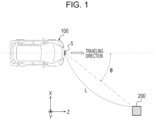
- FIG. 1 is a diagram for describing how the electronic device according to the one embodiment is used.
- FIG. 1 illustrates an example in which a sensor, including a transmission antenna and a reception antenna, according to the one embodiment is installed on a mobility device.
- a sensor 5, including a transmission antenna and a reception antenna, according to the one embodiment is installed on a mobility device 100 illustrated in FIG. 1 .
- the mobility device 100 illustrated in FIG. 1 includes an electronic device 1 according to the one embodiment mounted (for example, built) therein. A specific configuration of the electronic device 1 is described later.
- the sensor 5 may include at least one of the transmission antenna or the reception antenna, for example.
- the sensor 5 may appropriately include at least any of other functional units, such as at least part of a controller 10 ( FIG. 2 ) included in the electronic device 1.
- the mobility device 100 illustrated in FIG. 1 may be an automotive vehicle such as a passenger car but may be a mobility device of any type. In FIG. 1 , the mobility device 100 may move (travel or slowly travel), for example, in a positive Z-axis direction (traveling direction) illustrated in FIG. 1 or in another direction, or may be stationary without moving.
- the sensor 5 including the transmission antenna is installed on the mobility device 100.
- only one sensor 5 including the transmission antenna and the reception antenna is installed at a front portion of the mobility device 100.
- the position where the sensor 5 is installed on the mobility device 100 is not limited to the position illustrated in FIG. 1 and may be another appropriate position.
- the sensor 5 illustrated in FIG. 1 may be installed on a left side, on a right side, and/or at a rear portion of the mobility device 100.
- the number of such sensors 5 may be any number equal to or greater than 1 depending on various conditions (or requirements) such as a range and/or an accuracy of measurement performed at the mobility device 100.
- the sensor 5 may be installed inside the mobility device 100.
- the inside the mobility device 100 may be, for example, a space inside a bumper, a space inside a body, a space inside a headlight, or a space such as a driver's space.
- the sensor 5 transmits an electromagnetic wave as a transmission wave from the transmission antenna. For example, when a predetermined object (for example, an object 200 illustrated in FIG. 1 ) is located around the mobility device 100, at least part of the transmission wave transmitted from the sensor 5 is reflected off the object to become a reflected wave. For example, the reception antenna of the sensor 5 receives such a reflected wave. In this manner, the electronic device 1 mounted in the mobility device 100 can detect the object.
- a predetermined object for example, an object 200 illustrated in FIG. 1
- the sensor 5 including the transmission antenna may be typically a radar (Radio Detecting and Ranging) sensor that transmits and receives a radio wave.
- the sensor 5 is not limited to a radar sensor.
- the sensor 5 according to the one embodiment may be, for example, a sensor based on the LIDAR (Light Detection and Ranging, Laser Imaging Detection and Ranging) technology that uses an optical wave.
- LIDAR Light Detection and Ranging, Laser Imaging Detection and Ranging
- Each of these sensors can include, for example, a patch antenna. Since the technologies such as the radar and the LIDAR are already known, detailed description may be appropriately simplified or omitted.
- the electronic device 1 mounted in the mobility device 100 illustrated in FIG. 1 receives, from the reception antenna, the reflected wave of the transmission wave transmitted from the transmission antenna of the sensor 5. In this manner, the electronic device 1 can detect the predetermined object 200 located within a predetermined distance from the mobility device 100. For example, as illustrated in FIG. 1 , the electronic device 1 can measure a distance L between the mobility device 100, which is a vehicle of interest, and the predetermined object 200. The electronic device 1 can also measure a relative velocity between the mobility device 100, which is the vehicle of interest, and the predetermined object 200. The electronic device 1 can further measure a direction (an angle of arrival ⁇ ) from which the reflected wave from the predetermined object 200 arrives at the mobility device 100, which is the vehicle of interest.
- the object 200 may be, for example, at least any of an oncoming automobile traveling in a lane adjacent to a lane of the mobility device 100, an automobile traveling next to the mobility device 100, an automobile traveling in front of or behind the mobility device 100 in the same lane, or the like.
- the object 200 may also be any object located around the mobility device 100, such as a motorcycle, a bicycle, a stroller, a person such as a pedestrian, an animal, other forms of life such as an insect, a guardrail, a median strip, a road sign, a step on a sidewalk, a wall, or an obstacle.
- the object 200 may be in motion or stationary.
- the object 200 may be an automobile or the like that is parked or stationary around the mobility device 100.
- FIG. 1 a ratio between a size of the sensor 5 and a size of the mobility device 100 does not necessarily indicate an actual ratio.
- FIG. 1 illustrates the sensor 5 that is installed at an outer portion of the mobility device 100. However, in one embodiment, the sensor 5 may be installed at various positions of the mobility device 100. For example, in one embodiment, the sensor 5 may be installed inside a bumper of the mobility device 100 so as not to be seen in the appearance of the mobility device 100.
- the transmission antenna of the sensor 5 transmits a radio wave in a frequency band, such as a millimeter wave (equal to or higher than 30 GHz) or a quasi-millimeter wave (for example, around 20 GHz to 30 GHz).
- a radio wave having a frequency bandwidth of 4 GHz such as from 77 GHz to 81 GHz.
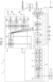
- FIG. 2 is a functional block diagram schematically illustrating an example of a configuration of the electronic device 1 according to the one embodiment. An example of the configuration of the electronic device 1 according to the one embodiment is described below.
- a frequency-modulated continuous wave radar (hereinafter, referred to as an FMCW radar) is often used.
- the FMCW radar sweeps a frequency of a to-be-transmitted radio wave to generate a transmission signal.
- a frequency of the radio wave used by such a millimeter-wave FMCW radar which uses a radio wave of a frequency band of 79 GHz, for example, has a frequency bandwidth of 4 GHz such as from 77 GHz to 81 GHz, for example.
- the radar of the frequency band of 79 GHz has a feature that a usable frequency bandwidth is wider than other millimeter-wave and/or quasi-millimeter-wave radars of frequency bands of 24 GHz, 60 GHz, and 76 GHz, for example. Such an embodiment is described below.
- the electronic device 1 includes the sensor 5 and an ECU (Electronic Control Unit) 50.
- the ECU 60 controls various operations of the mobility device 100.
- the ECU 60 may include at least one or more ECUs.
- the "electronic device” may mean, for example, the electronic device 1 illustrated in FIG. 2 (that is, including the sensor 5 and the ECU 60, for example) or may mean, for example, the sensor 5 illustrated in FIG. 2 .
- the electronic device 1 includes the controller 10.
- the electronic device 1 according to the one embodiment may also appropriately include another functional unit such as at least any of a transmission unit 20 or reception units 30A to 30D.
- the electronic device 1 may include multiple reception units such as the reception units 30A to 30D.
- the reception units 30A, 30B, 30C, and 30D are simply referred to as "reception units 30" below.
- the controller 10 may include a distance FFT processing unit 11, a velocity FFT processing unit 12, an angle-of-arrival estimating unit 13, and an object detecting unit 14. These functional units included in the controller 10 are further described later.
- the transmission unit 20 may include a signal generating unit 21, a synthesizer 22, phase control units 23A, 23B, and 23C, amplifiers 24A, 24B, and 24C, and transmission antennas 26A, 26B, and 26C.
- phase control units 23A, 23B, and 23C are simply referred to as "phase control units 23" below.
- amplifiers 24A, 24B, and 24C are not distinguished from one another, the amplifiers 24A, 24B, and 24C are simply referred to as "amplifiers 24" below.
- the transmission antennas 26A, 26B, and 26C are simply referred to as "transmission antennas 26" below.
- each of the reception units 30 may include a respective one of reception antennas 31A to 31D.
- the reception antennas 31A, 31B, 31C, and 31D are simply referred to as "reception antennas 31" below.
- each of the plurality of reception units 30 may include an LNA 33, a phase control unit 34, a mixer 35, an IF unit 36, and an AD conversion unit 37.
- the reception units 30A to 30D may have the same and/or similar configuration.
- FIG. 2 schematically illustrates the configuration of the reception unit 30A alone as a representative example.
- the sensor 5 described above may include, for example, the transmission antennas 26 and the reception antennas 31.
- the sensor 5 may also appropriately include at least any of other functional units such as the controller 10.
- the controller 10 included in the electronic device 1 is capable of controlling the individual functional units of the electronic device 1 and controlling operations of the entire electronic device 1.
- the controller 10 may include at least one processor, for example, a CPU (Central Processing Unit) or a DSP (Digital Signal Processor).
- the controller 10 may be collectively implemented by one processor, may be implemented by some processors, or may be implemented by discrete individual processors.
- the processor may be implemented as one integrated circuit.
- the integrated circuit is also referred to as an IC.
- the processor may be implemented as multiple integrated circuits and discrete circuits connected to be able to perform communication.
- the processor may be implemented based on various other known technologies.
- the controller 10 may be configured as, for example, a CPU and a program executed by the CPU.
- the controller 10 may include a memory of any type as appropriate.
- the memory of any type may store various parameters for setting a range in which an object is detected based on a transmission wave T transmitted from each transmission antenna 26 and a reflected wave R received from each reception antenna 31.
- the controller 10 is capable of controlling at least one of the transmission unit 20 or the reception units 30.
- the controller 10 may control at least one of the transmission unit 20 or the reception units 30, based on various kinds of information stored in the memory of any type, for example.
- the controller 10 may instruct the signal generating unit 21 to generate a signal or may control the signal generating unit 21 to generate a signal.
- the signal generating unit 21 In accordance with control performed by the controller 10, the signal generating unit 21 generates a signal (transmission signal) to be transmitted as the transmission wave T from each of the transmission antennas 26.
- the signal generating unit 21 may allocate a frequency of the transmission signal in accordance with control performed by the controller 10, for example.
- the signal generating unit 21 may allocate the frequency of the transmission signal in accordance with a parameter set by the controller 10.
- the signal generating unit 21 receives frequency information from the controller 10 and generates a signal having a predetermined frequency in a frequency band such as from 77 GHz to 81 GHz, for example.
- the signal generating unit 21 may include a functional unit such as a voltage control oscillator (VCO), for example.
- VCO voltage control oscillator
- the signal generating unit 21 may be configured as hardware having the function, for example as a microcomputer, or for example as a processor such as a CPU and a program or the like executed by the processor.
- Each functional unit described below may also be configured as hardware having the function, for example as a microcomputer if possible, or for example as a processor such as a CPU and a program or the like executed by the processor if possible.
- the signal generating unit 21 may generate a transmission signal (transmission chirp signal) such as a chirp signal, for example.
- the signal generating unit 21 may generate a signal (linear chirp signal) whose frequency changes linearly and periodically.
- the signal generating unit 21 may generate a chirp signal whose frequency linearly and periodically increases from 77 GHz to 81 GHz as time elapses.
- the signal generating unit 21 may generate a signal whose frequency periodically repeats a linear increase (up-chirp) from 77 GHz to 81 GHz and a decrease (down-chirp) as time elapses.
- the controller 10 may set in advance the signal generated by the signal generating unit 21.
- the memory of any type or the like may store in advance the signal generated by the signal generating unit 21. Since a chirp signal used in a technical field such as the radar is known, more detailed description is appropriately simplified or omitted.
- the signal generated by the signal generating unit 21 is supplied to the synthesizer 22.
- FIG. 3 is a diagram for describing an example of chirp signals generated by the signal generating unit 21.
- the horizontal axis represents elapsed time
- the vertical axis represents a frequency.
- the signal generating unit 21 generates linear chirp signals whose frequency changes linearly and periodically.
- FIG. 3 illustrates chirp signals c1, c2, ..., c8.
- the frequency of each chirp signal linearly increases as time elapses.
- one subframe includes eight chirp signals c1, c2, ..., c8. That is, each of subframes such as a subframe 1 and a subframe 2 illustrated in FIG. 3 includes eight chirp signals c1, c2, ..., c8.
- one frame includes 16 subframes such as the subframes 1 to 16. That is, each of frames such as a frame 1 and a frame 2 illustrated in FIG. 3 includes 16 subframes.
- a frame interval of a predetermined length may be included between frames.
- Each single frame illustrated in FIG. 3 may have a length of about 30 ms to 50 ms, for example.
- the frame 2 and subsequent frames may have the same and/or similar configuration.
- the frame 3 and subsequent frames may have the same and/or similar configuration.
- the signal generating unit 21 may generate a transmission signal as any number of frames.
- an illustration of some chirp signals is omitted.
- the memory of any type or the like may store a relationship between time and a frequency of the transmission signal generated by the signal generating unit 21.
- the electronic device 1 may transmit a transmission signal made up of subframes each including multiple chirp signals.
- the electronic device 1 according to the one embodiment may transmit a transmission signal made up of frames each including a predetermined number of subframes.
- the electronic device 1 transmits a transmission signal having the frame structure illustrated in FIG. 3 .
- the frame structure illustrated in FIG. 3 is an example.
- the number of chirp signals included in one subframe is not limited to eight.
- the signal generating unit 21 may generate a subframe including any number of (for example, multiple) chirp signals.
- the subframe structure illustrated in FIG. 3 is also an example.
- the number of subframes included in one frame is not limited to 16.
- the signal generating unit 21 may generate a frame including any number of (for example, multiple) subframes.
- the signal generating unit 21 may generate signals having different frequencies.
- the signal generating unit 21 may generate multiple discrete signals of bandwidths in which frequencies f are different from each other.
- the synthesizer 22 increases the frequency of the signal generated by the signal generating unit 21 to a frequency in a predetermined frequency band.
- the synthesizer 22 may increase the frequency of the signal generated by the signal generating unit 21 to a frequency selected as a frequency of the transmission wave T to be transmitted from each of the transmission antennas 26.
- the controller 10 may set the frequency selected as the frequency of the transmission wave T to be transmitted from each of the transmission antennas 26.
- the frequency selected as the frequency of the transmission wave T to be transmitted from each of the transmission antennas 26 may be a frequency selected by the controller 10.
- the memory of any type may store the frequency selected as the frequency of the transmission wave T to be transmitted from each of the transmission antennas 26.
- the signal whose frequency has been increased by the synthesizer 22 is supplied to the phase control unit 23 and the mixer 35.
- the signal whose frequency has been increased by the synthesizer 22 may be supplied to each of the multiple phase control units 23.
- the signal whose frequency has been increased by the synthesizer 22 may be supplied to the mixer 35 of each of the multiple reception units 30.
- Each of the phase control units 23 controls (adjusts) a phase of the transmission signal supplied from the synthesizer 22. Specifically, for example, in accordance with control performed by the controller 10, each of the phase control units 23 may appropriately advance or delay the phase of the signal supplied from the synthesizer 22 to adjust the phase of the transmission signal. In this case, based on a difference between paths of the transmission waves T to be transmitted from the multiple transmission antennas 26, the phase control units 23 may adjust the phases of the respective transmission signals. The phase control units 23 appropriately adjust the phases of the respective transmission signals, so that the transmission waves T transmitted from the multiple transmission antennas 26 enhance with one another in a predetermined direction to form a beam (beamforming).
- the memory of any type may store a correlation between a direction of beamforming and amounts of phase by which the respective transmission signals to be transmitted by the multiple transmission antennas 26 are to be controlled.
- Each of the phase control units 23 may include, for example, a phase shifter of any type. The transmission signal whose phase is controlled by each of the phase control units 23 is supplied to a respective one of the amplifiers 24.
- the amplifier 24 amplifies power (electric power) of the transmission signal supplied from the phase control unit 23 in accordance with control performed by the controller 10, for example.
- each of the multiple amplifiers 24 may amplify power (electric power) of the transmission signal supplied from a respective one of the multiple phase control units 23 in accordance with control performed by the controller 10, for example. Since the technology for amplifying power of a transmission signal is already known, more detailed description is omitted.
- the amplifier 24 is connected to the transmission antenna 26.
- the transmission antenna 26 outputs (transmits), as the transmission wave T, the transmission signal amplified by the amplifier 24.
- each of the multiple transmission antennas 26 may output (transmit), as the transmission wave T, the transmission signal amplified by a respective one of the multiple amplifiers 24. Since the transmission antennas 26 can have a configuration that is the same as and/or similar to the configuration of transmission antennas for use in the known radar technology, more detailed description is omitted.
- the electronic device 1 which includes the transmission antennas 26, can transmit transmission signals (for example, transmission chirp signals) as the transmission waves T from the respective transmission antennas 26.
- transmission signals for example, transmission chirp signals
- At least one of the functional units of the electronic device 1 may be housed in one housing.
- the one housing may have a hard-to-open structure.
- the transmission antennas 26, the reception antennas 31, and the amplifiers 24 are desirably housed in one housing, and this housing desirably has a hard-to-open structure.
- each of the transmission antennas 26 may transmit the transmission wave T to outside the mobility device 100 through a cover member such as a radar cover, for example.
- the radar cover may be made of a material, for example, a synthetic resin or rubber, that allows an electromagnetic wave to pass therethrough.
- This radar cover may also serve as a housing of the sensor 5, for example. Covering the transmission antennas 26 with a member such as the radar cover can reduce a risk of the transmission antennas 26 being damaged or malfunctioning because of a contact with an external object.
- the radar cover and the housing may also be referred to as a radome.
- FIG. 2 illustrates an example of the electronic device 1 that includes three transmission antennas 26.
- the electronic device 1 may include any number of transmission antennas 26.
- the electronic device 1 may include the multiple transmission antennas 26 when the transmission waves T transmitted from the respective transmission antennas 26 form a beam in a predetermined direction.
- the electronic device 1 may include the multiple phase control units 23 and the multiple amplifiers 24 to correspond to the multiple transmission antennas 26.
- Each of the multiple phase control units 23 may control the phase of a respective one of the multiple transmission waves supplied from the synthesizer 22 and to be transmitted from the respective transmission antennas 26.
- Each of the multiple amplifiers 24 may amplify power of a respective one of the multiple transmission signals to be transmitted from the respective transmission antennas 26.
- the sensor 5 may include the multiple transmission antennas.
- the electronic device 1 illustrated FIG. 2 includes the multiple transmission antennas 26, the electronic device 1 may include multiple functional units necessary for transmitting the transmission waves T from the multiple transmission antennas 26.
- the reception antenna 31 receives the reflected wave R.
- the reflected wave R is the transmission wave T reflected off the predetermined object 200.
- multiple antennas such as the reception antennas 31A to 31D, for example, may be included. Since the reception antennas 31 can have a configuration that is the same as and/or similar to the configuration of reception antennas for use in the known radar technology, more detailed description is omitted.
- the reception antenna 31 is connected to the LNA 33. A reception signal based on the reflected wave R received by the reception antenna 31 is supplied to the LNA 33.
- the electronic device 1 can receive, from each of the multiple reception antennas 31, the reflected wave R that is the transmission wave T that has been transmitted as the transmission signal (transmission chirp signal) such as a chirp signal, for example, and has been reflected off the predetermined object 200.
- the transmission chirp signal is transmitted as the transmission wave T in this manner
- the reception signal based on the received reflected wave R is referred to as a reception chirp signal. That is, the electronic device 1 receives the reception signal (for example, the reception chirp signal) as the reflected wave R from each of the reception antennas 31.
- each of the reception antennas 31 may receive the reflected wave R from outside the mobility device 100 through a cover member such as a radar cover, for example.
- the radar cover may be made of a material, for example, a synthetic resin or rubber, that allows an electromagnetic wave to pass therethrough.
- This radar cover may also serve as a housing of the sensor 5, for example. Covering the reception antennas 31 with a member such as the radar cover can reduce a risk of the reception antennas 31 being damaged or malfunctioning because of a contact with an external object.
- the radar cover and the housing may also be referred to as a radome.
- the reception antenna 31 When the reception antenna 31 is installed near the transmission antenna 26, these reception antenna 31 and transmission antenna 26 may be collectively included in one sensor 5. That is, for example, the one sensor 5 may include at least one transmission antenna 26 and at least one reception antenna 31.
- the one sensor 5 may include the multiple transmission antennas 26 and the multiple reception antennas 31.
- one radar sensor may be covered with a cover member such as one radar cover, for example.
- the LNA 33 amplifies, with low noise, the reception signal based on the reflected wave R received by the reception antenna 31.
- the LNA 33 may be a low-noise amplifier and amplifies, with low noise, the reception signal supplied from the reception antenna 31.
- the reception signal amplified by the LNA 33 is supplied to the phase control unit 34.
- the phase control unit 34 controls (adjusts) a phase of the reception signal supplied from the LNA 33. Specifically, for example, in accordance with control performed by the controller 10, the phase control unit 34 may appropriately advance or delay the phase of the signal supplied from the LNA 33 to adjust the phase of the reception signal. In this case, based on a difference between paths of the reflected waves R received from the multiple reception antennas 31, the phase control units 34 may adjust the phases of the respective reception signals. In this case, for example, the memory of any type may store amounts of phase by which the respective reception signals received from the multiple reception antennas 31 are to be controlled.
- the phase control unit 34 may include, for example, a phase shifter of any type. The transmission signal whose phase is controlled by the phase control unit 34 is supplied to the mixer 35.
- the mixer 35 mixes (multiplies) the reception signal having a radio frequency (RF) and supplied from the phase control unit 34 and the transmission signal supplied from the synthesizer 22 to generate a beat signal.
- the beat signal obtained by the mixer 35 through mixing is supplied to the IF unit 36.
- the IF unit 36 performs frequency conversion on the beat signal supplied from the mixer 35 to decrease the frequency of the beat signal to an intermediate frequency (IF).
- IF intermediate frequency
- the beat signal whose frequency has been decreased by the IF unit 36 is supplied to the AD conversion unit 37.
- the AD conversion unit 37 digitizes the analog beat signal supplied from the IF unit 36.
- the AD conversion unit 37 may be configured as an analog-to-digital conversion circuit (Analog-to-Digital Converter (ADC)) of any type.
- ADC Analog-to-Digital Converter
- the digitized beat signal obtained by the AD conversion unit 37 is supplied to the distance FFT processing unit 11 of the controller 10.
- the digitized beat signals obtained by the respective AD conversion units 37 may be supplied to the distance FFT processing unit 11.
- the distance FFT processing unit 11 estimates a distance between the mobility device 100 equipped with the electronic device 1 and the object 200, based on the beat signals supplied from the respective AD conversion units 37.
- the distance FFT processing unit 11 may include a processing unit that performs fast Fourier transform, for example.
- the distance FFT processing unit 11 may be configured as a circuit, chip, or the like of any type that performs fast Fourier transform (FFT).
- the distance FFT processing unit 11 performs FFT processing (hereinafter, appropriately referred to as "distance FFT processing") on the digitized beat signals obtained by the AD conversion units 37.
- the distance FFT processing unit 11 may perform FFT processing on complex signals supplied from the AD conversion units 37.
- the digitized beat signals obtained by the AD conversion units 37 can be represented as temporal changes in signal intensity (power).
- the distance FFT processing unit 11 performs FFT processing on such beat signals, so that the beat signals can be represented as a signal intensity (power) for each frequency. If a peak in a result obtained by the distance FFT processing is equal to or greater than a predetermined threshold, the distance FFT processing unit 11 may determine that the predetermined object 200 is located at the distance corresponding to the peak.
- a method for determining that an object (reflecting object) that reflects a transmission wave is located when a peak value that is equal to or greater than a threshold is detected from the average power or amplitude of a disturbance signal, such as a constant false alarm rate (CFAR) detection process, is known.
- the electronic device 1 can detect the object 200 that reflects the transmission wave T, based on the transmission signal transmitted as the transmission wave T and the reception signal received as the reflected wave R.
- the distance FFT processing unit 11 can estimate a distance to a predetermined object, based on one chirp signal (for example, c1 illustrated in FIG. 3 ). That is, the electronic device 1 can measure (estimate) the distance L illustrated in FIG. 1 by performing the distance FFT processing. Since a technique for measuring (estimating) a distance to a predetermined object by performing FFT processing on a beat signal is known, more detailed description is appropriately simplified or omitted. Results (for example, distance information) of the distance FFT processing performed by the distance FFT processing unit 11 may be supplied to the velocity FFT processing unit 12. The results of the distance FFT processing performed by the distance FFT processing unit 11 may also be supplied to the object detecting unit 14.
- the velocity FFT processing unit 12 estimates a relative velocity between the mobility device 100 equipped with the electronic device 1 and the object 200, based on the beat signals on which the distance FFT processing has been performed by the distance FFT processing unit 11.
- the velocity FFT processing unit 12 may include a processing unit that performs fast Fourier transform, for example.
- the velocity FFT processing unit 12 may be configured as a circuit, chip, or the like of any type that performs fast Fourier transform (FFT).
- the velocity FFT processing unit 12 further performs FFT processing (hereinafter, appropriately referred to as "velocity FFT processing") on the beat signals on which the distance FFT processing unit 11 has performed the distance FFT processing.
- the velocity FFT processing unit 12 may perform FFT processing on the complex signals supplied from the distance FFT processing unit 11.
- the velocity FFT processing unit 12 can estimate a relative velocity to the predetermined object, based on a subframe (for example, the subframe 1 illustrated in FIG. 3 ) including chirp signals.
- the velocity FFT processing unit 12 can estimate a relative velocity to the predetermined object by determining a phase of a peak in a result of the velocity FFT processing performed on these multiple vectors. That is, the electronic device 1 can measure (estimate) a relative velocity between the mobility device 100 and the predetermined object 200 illustrated in FIG. 1 by performing the velocity FFT processing. Since a technique for measuring (estimating) a relative velocity to a predetermined object by performing velocity FFT processing on a result of distance FFT processing is known, more detailed description is appropriately simplified or omitted. Results (for example, velocity information) of the velocity FFT processing performed by the velocity FFT processing unit 12 may be supplied to the angle-of-arrival estimating unit 13. The results of the velocity FFT processing performed by the velocity FFT processing unit 12 may also be supplied to the object detecting unit 14.
- the angle-of-arrival estimating unit 13 estimates a direction from which the reflected wave R arrives from the predetermined object 200, based on the result of the velocity FFT processing performed by the velocity FFT processing unit 12.
- the electronic device 1 can estimate the direction from which the reflected wave R arrives by receiving the reflected wave R from the multiple reception antennas 31.
- the multiple reception antennas 31 are arranged at a predetermined interval. In this case, the transmission wave T transmitted from the transmission antenna 26 is reflected off the predetermined object 200 to become the reflected wave R.
- Each of the multiple reception antennas 31 arranged at the predetermined interval receives the reflected wave R.
- the angle-of-arrival estimating unit 13 can estimate the direction from which the reflected wave R arrives at each of the multiple reception antennas 31, based on the phase of the reflected wave R received by the reception antenna 31 and a difference in path of the reflected wave R. That is, the electronic device 1 can measure (estimate) the angle of arrival ⁇ illustrated in FIG. 1 , based on the result of the velocity FFT processing.
- Various techniques for estimating a direction from which the reflected wave R arrives, based on a result of velocity FFT processing have been proposed.
- known direction-of-arrival estimation algorithms include MUSIC (MUltiple Signal Classification), ESPRIT (Estimation of Signal Parameters via Rotational Invariance Technique), and the like.
- MUSIC MUltiple Signal Classification
- ESPRIT Estimat of Signal Parameters via Rotational Invariance Technique
- the object detecting unit 14 detects an object located in a range in which the transmission waves T are transmitted, based on the information supplied from at least any of the distance FFT processing unit 11, the velocity FFT processing unit 12, or the angle-of-arrival estimating unit 13.
- the object detecting unit 14 may perform detection of an object by performing, for example, clustering processing based on the supplied distance information, velocity information, and angle information.
- clustering processing for example, average power of points constituting the detected object may be calculated.
- the distance information, the velocity information, the angle information, and the power information of the object detected by the object detecting unit 14 may be supplied to the ECU 60.
- communication may be performed using a communication interface such as a CAN (Controller Area Network), for example.
- the controller 10 sets various parameters that define a transmission signal and a reception signal with which an object that reflects the transmission wave T as the reflected wave R is to be detected. That is, the controller 10 may set various parameters for transmitting the transmission wave T from the transmission antenna 26 and various parameters for receiving the reflected wave R from the reception antenna 31.
- the controller 10 may set various parameters related to transmission of the transmission wave T and reception of the reflected wave R in order to detect an object.
- the controller 10 may define a range or the like in which the reflected wave R is desirably received in order to detect the object located in an object detection range by receiving the reflected wave R.
- the controller 10 may define a range or the like to which a beam of the transmission waves T is desirably directed in order to detect an object located in the object detection range by transmitting the transmission waves T from the multiple transmission antennas 26.
- the controller 10 may also set various parameters for transmitting the transmission wave T and receiving the reflected wave R.
- the various parameters set by the controller 10 may be supplied to the signal generating unit 21.
- the signal generating unit 21 can generate the transmission signal to be transmitted as the transmission waves T, based on the various parameters set by the controller 10.
- the various parameters set by the controller 10 may be supplied to the object detecting unit 14.
- the object detecting unit 14 can perform object detection processing in the object detection range determined based on the various parameters set by the controller 10.
- the ECU 60 included in the electronic device 1 is capable of controlling functional units of the mobility device 100 and controlling operations of the entire mobility device 100.
- the ECU 60 may include at least one processor, for example, a CPU (Central Processing Unit) or a DSP (Digital Signal Processor).
- the ECU 60 may be collectively implemented by one processor, may be implemented by some processors, or may be implemented by discrete individual processors.
- the processor may be implemented as one integrated circuit.
- the integrated circuit is also referred to as an IC.
- the processor may be implemented as multiple integrated circuits and discrete circuits connected to be able to perform communication.
- the processor may be implemented based on various other known technologies.
- the ECU 60 may be configured as, for example, a CPU and a program executed by the CPU.
- the ECU 60 may appropriately include a memory necessary for operations of the ECU 60.
- At least part of the functions of the controller 10 may be functions of the ECU 60, or at least part of the functions of the ECU 60 may be functions of the controller 10.
- the electronic device 1 illustrated in FIG. 2 includes the three transmission antennas 26 and the four reception antennas 31.
- the electronic device 1 according to the one embodiment may include any number of (multiple) transmission antennas 26 and any number of (multiple) reception antennas 31.
- the electronic device 1 according to the one embodiment may include the multiple transmission antennas 26 that transmit respective transmission waves, and the multiple reception antennas 31 that receive respective reflected waves that are the reflected transmission waves.
- the electronic device 1 when the electronic device 1 includes the two transmission antennas 26 and the four reception antennas 31, the electronic device 1 can be regarded to include a virtual antenna array virtually including eight antennas.
- the electronic device 1 may receive the reflected wave R of 16 subframes illustrated in FIG. 3 by using, for example, the eight virtual antennas.
- the configuration of the sensor 5 included in the electronic device 1 according to the one embodiment is further described. Prior to description of a specific configuration of the sensor 5 included in the electronic device 1 according to the one embodiment, a sensor generally assumed as a device such as a known radar sensor is described.
- FIG. 4 is a diagram illustrating a comparative example for describing an arrangement of the transmission antennas, the reception antennas, and an electronic component in the electronic device 1 according to the one embodiment. That is, FIG. 4 is a diagram illustrating a configuration of a sensor assumed as a target to be compared with the sensor 5 included in the electronic device 1 according to the one embodiment.
- a sensor 50 illustrated in FIG. 4 includes the multiple transmission antennas 26, the multiple reception antennas 31, and an electronic component 40.
- the multiple transmission antennas 26, the multiple reception antennas 31, and the electronic component 40 may be arranged on a planar substrate parallel to an XY plane, for example.
- the sensor 50 may include the transmission antennas 26A, 26B, and 26C, for example.
- the transmission antennas 26A, 26B, and 26C are simply referred to as "transmission antennas 26" below.
- the multiple transmission antennas 26 illustrated in FIG. 4 may correspond to the multiple transmission antennas 26 described in FIG. 2 , for example.
- the sensor 50 may include, for example, the reception antennas 31A, 31B, 31C, and 31D.
- the reception antennas 31A, 31B, 31C, and 31D are simply referred to as "reception antennas 31" below.
- the multiple reception antennas 31 illustrated in FIG. 4 may correspond to the multiple reception antennas 31 described with reference to FIG. 2 , for example.
- the multiple transmission antennas 26 and the multiple reception antennas 31 illustrated in FIG. 4 each are depicted as four patch antennas (microstrip antennas) connected in series in a longitudinal direction (a Y-axis direction illustrated in FIG. 4 ).
- the multiple transmission antennas 26 and the multiple reception antennas 31 each may be any number of patch antennas or antennas of another form.
- the patch antennas of each of the multiple transmission antennas 26 and the multiple reception antennas 31 illustrated in FIG. 4 are disposed with positions thereof being aligned in the longitudinal direction (the Y-axis direction illustrated in FIG. 4 ).
- the patch antennas of each of the multiple transmission antennas 26 and the multiple reception antennas 31 may be arranged with positions thereof being shifted in the longitudinal direction (the Y-axis direction illustrated in FIG. 4 ).
- the patch antennas of each of the multiple transmission antennas 26 and the multiple reception antennas 31 illustrated in FIG. 4 are depicted as quadrangular (rectangular) microstrip antennas but may have another shape such as circular microstrip antennas
- the electronic component 40 illustrated in FIG. 4 may be, for example, a component including at least part of the functions of at least any of the transmission unit 20, the reception units 30, and the controller 10 illustrated in FIG. 2 .
- the electronic component 40 illustrated in FIG. 4 may be a component including all the functions of the transmission unit 20, the reception units 30, and the controller 10 illustrated in FIG. 2 .
- the electronic component 40 illustrated in FIG. 4 may output respective transmission signals to the multiple transmission antennas 26 and receive respective reception signals from the multiple reception antennas 31.
- the electronic component 40 may be, for example, a packaged semiconductor integrated circuit such as a chip or a die.
- the electronic component 40 may be, for example, a SoC (System-on-a-chip). That is, the electronic component 40 may be an integrated circuit product in which functions for application purposes as well as functions of a general microcontroller including a processor core are integrated in a single chip of an integrated circuit and are designed to operate in cooperation to function as a system.
- SoC System-on-a-chip
- the electronic component 40 may have, for example, a quadrangular shape.
- the electronic component 40 may at least have a first edge 41 and a second edge 42.
- the first edge 41 may be an edge in a substantially vertical direction, that is, an edge substantially parallel to the Y-axis direction illustrated in FIG. 4 .
- the second edge 42 may be an edge in a substantially horizontal direction, that is, an edge substantially parallel to the X-axis direction illustrated in FIG. 4 .
- the first edge 41 of the electronic component 40 illustrated in FIG. 4 may be an edge where multiple transmission terminals (for example, p1 to p3) that output respective transmission signals to the multiple transmission antennas 26 are arranged.
- the multiple transmission terminals p1 to p3 illustrated in FIG. 4 may be, for example, output ports.
- feeding points (f1 to f3) of the multiple transmission antennas 26A to 26C and the multiple transmission terminals (p1 to p3) at the first edge 41 of the electronic component 40 may be connected by transmission lines (25A to 25C), respectively.
- the second edge 42 of the electronic component 40 illustrated in FIG. 4 may be an edge where multiple reception terminals (for example, p4 to p7) that receive respective reception signals from the multiple reception antennas 31 are arranged.
- the multiple reception terminals p4 and p7 illustrated in FIG. 4 may be, for example, input ports.
- feeding points (f4 to f7) of the multiple reception antennas 31A to 31D and the multiple reception terminals (p4 to p7) at the second edge 42 of the electronic component 40 may be connected by transmission lines (32A to 32D), respectively.
- the sensor 50 illustrated in FIG. 4 may control phases of RF signals to be output to the respective feeding points (f1 to f3) of the multiple transmission antennas 26.
- the sensor 50 illustrated in FIG. 4 can control the directivity of the multiple transmission antennas 26.
- the transmission lines (25A to 25C) from the multiple transmission terminals (p1 to p3) of the electronic component 40 to the feeding points (f1 to f3) of the multiple transmission antennas 26 may be wires having an equal length, respectively.
- the sensor 50 can make a phase difference of the transmission signals at the multiple transmission antennas 26 zero.
- the transmission lines (25A to 25C) of the respective transmission signals may have the equal length.
- the directivity of combined power can be set to 0 deg. through software processing.
- the sensor 50 illustrated in FIG. 4 may detect phase differences between RF signals input from the multiple reception antennas 31 to the multiple reception terminals (p4 to p7) of the electronic component 40. Thus, the sensor 50 illustrated in FIG. 4 can estimate the direction of arrival of the reflected wave that is the transmission wave reflected off an object (for example, the ESPRIT method). As illustrated in FIG. 4 , the transmission lines (32A to 32D) from the feeding points (f4 to f7) of the multiple reception antennas 31 to the multiple reception terminals (p4 to p7) of the electronic component 40 may be wires having an equal length, respectively. Thus, the sensor 50 can make a phase difference of the reception signals at the multiple reception antennas 31 zero.
- the transmission lines (32A to 32D) of the respective reception signals may have the equal length.
- the phase difference of the signals at the direction of arrival of 0 deg. can be set to 0 deg. through software processing.
- setting the transmission lines (25A to 25C) of the respective transmission signals and/or the transmission lines (32A to 32D) of the respective reception signals to have equal lengths can make the initial value of the phase difference of the signals 0 deg.
- the transmission lines (25A to 25C) of the respective transmission signals and/or the transmission lines (32A to 32D) of the respective reception signals have equal lengths
- at least some of the transmission lines are to be wired to detour.
- the transmission line 25C illustrated in FIG. 4 is wired to detour on a substrate as compared with the transmission lines 25A and 25B.
- the transmission lines 32B and 32C illustrated in FIG. 4 are wired to detour on the substrate as compared with the transmission lines 32A and 32D.
- the transmission lines wired to detour on the substrate in this manner are longer than the transmission lines connected with shortest paths. As the transmission line becomes longer, a loss of the signal passing through the transmission line may increase.
- a mounting area of the transmission line increases on the substrate. This may make it difficult to reduce the size of the device.
- the transmission lines of the respective transmission signals and/or the transmission lines of the respective reception signals are made as short as possible. Such an embodiment is further described below.
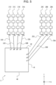
- FIG. 5 is a diagram illustrating a configuration example of the sensor 5 according to the one embodiment. Specifically, FIG. 5 is a diagram illustrating an example of the arrangement of the multiple transmission antennas 26, the multiple reception antennas 31, and the electronic component 40 in the electronic device (the sensor 5) according to the one embodiment.
- the transmission lines (25A to 25C) of the respective transmission signals and the transmission lines (32A to 32D) of the respective reception signals have shapes different from those of the sensor 50 illustrated in FIG. 4 .
- the transmission lines (25A to 25C) of the respective transmission signals and the transmission lines (32A to 32D) of the respective reception signals are linearly wired.
- the transmission lines (25A to 25C) of the respective transmission signals and the transmission lines (32A to 32D) of the respective reception signals can have lengths of shortest paths or lengths close to the shortest paths.
- the electronic component 40 implements a function different from that of the electronic component 40 of the sensor 50 illustrated in FIG. 4 .
- the senor 5 can be configured in the same manner as the sensor 50 illustrated in FIG. 4 .
- the same or similar description as that of the sensor 50 illustrated in FIG. 4 will be appropriately simplified or omitted.
- the feeding points (f1 to f3) of the multiple transmission antennas 26 may be connected to the multiple transmission terminals (p1 to p3) by the transmission lines (25A to 25C), respectively.
- the feeding points (f4 to f7) of the multiple reception antennas 31 may be connected to the multiple reception terminals (p4 to p7) by the transmission lines (32A to 32D), respectively.
- the feeding points (f1 to f3) of the multiple transmission antennas 26 may be connected to the multiple transmission terminals (p1 to p3) by the transmission lines (25A to 25C) with the shortest paths, respectively.
- the feeding points (f4 to f7) of the multiple reception antennas 31 may be connected to the multiple reception terminals (p4 to p7) by the transmission lines (32A to 32D) with the shortest paths, respectively.
- the electronic component 40 of the sensor 5 illustrated in FIG. 5 outputs respective transmission signals to the multiple transmission antennas 26 and receives respective reception signals from the multiple reception antennas 31.
- the electronic component 40 has the function of at least one of the phase control units 23 of the transmission unit 20 or the phase control units 34 of the respective reception units 30 illustrated in FIG. 2 .
- the electronic component 40 of the sensor 5 illustrated in FIG. 5 may include a function other than the function of at least one of the phase control units 23 of the transmission unit 20 or the phase control units 34 of the respective reception units 30 illustrated in FIG. 2 as appropriate.
- the electronic component 40 illustrated in FIG. 5 controls (adjusts) the phases of the respective transmission signals to be output from the multiple transmission terminals (p1 to p3) to the multiple transmission antennas 26 with the function of the phase control units 23 of the transmission unit 20.
- the phase control units 23 of the transmission unit 20 may adjust the phases of the respective transmission signals in accordance with the respective lengths of the multiple transmission lines (25A to 25C) of the transmission signals. In general, a signal delays more in a longer transmission line among multiple transmission lines of transmission signals.
- the phase control units 23 of the transmission unit 20 may adjust the phases of the respective transmission signals in advance such that the phase of the signal is advanced more for the longer transmission line among the multiple transmission lines of the transmission signals, for example.
- the phase control units 23 of the transmission unit 20 may adjust the phases of the respective transmission signals such that the transmission signals are in phase at the feeding points (f1 to f3) of the multiple transmission antennas 26.
- the electronic component 40 may adjust the phases of the respective transmission signals to be output from the multiple transmission terminals (p1 to p3).
- the electronic component 40 may adjust the phases of the respective transmission signals to be output from the multiple transmission terminals (p1 to p3), in accordance with the lengths of the transmission lines (f1 to f3) from the multiple transmission terminals (25A to 25C) to the feeding points (p1 to p3) of the multiple transmission antennas 26, respectively.
- the electronic component 40 may adjust the phases of the respective transmission signals such that the transmission signals to be output from the multiple transmission terminals (p1 to p3) are in phase at the feeding points (f1 to f3) of the multiple transmission antennas 26, respectively.
- the electronic component 40 illustrated in FIG. 5 controls (adjusts) the phases of the respective reception signals input from the multiple reception antennas 31 to the multiple reception terminals (p4 to p7) with the function of the phase control units 34 of the respective reception units 30.
- the phase control units 34 of the respective reception units 30 may adjust the phases of the respective reception signals in accordance with the respective lengths of the multiple transmission lines (32A to 32D) of the reception signals. In general, a signal delays more in a longer transmission line among multiple transmission lines of reception signals.
- the phase control units 34 of the respective reception units 30 may adjust the phases of the respective reception signals such that the phase of the signal is advanced more for the longer transmission line among the multiple transmission lines of the reception signals, for example.
- the phase control units 34 of the respective reception units 30 may adjust the phases of the respective reception signals such that the reception signals are in phase at the multiple reception terminals (p4 to p7) of the electronic component 40.
- the electronic component 40 may adjust the phases of the respective reception signals input to the multiple reception terminals (p4 to p7).
- the electronic component 40 may adjust the phases of the respective reception signals input to the multiple reception terminals (p4 to p7), in accordance with the lengths of the transmission lines (32A to 32D) from the feeding points (f4 to f7) of the multiple reception antennas 31 to the multiple reception terminals (p4 to p7), respectively.
- the electronic component 40 may adjust the phases of the respective reception signals such that the reception signals input to the multiple reception terminals (p4 to p7) are in phase.
- the transmission lines (25A to 25C) from the multiple transmission terminals (p1 to p3) to the feeding points (f1 to f3) of the multiple transmission antennas 26 have different lengths.
- a phase difference occurs in the transmission signals at the feeding points (f1 to f3) of the multiple transmission antennas 26.
- ⁇ 1 denotes an amount of phase shift in the transmission line 25A
- ⁇ 2 denotes an amount of phase shift in the transmission line 25B
- ⁇ 3 denotes an amount of phase shift in the transmission line 25C.
- a relationship of ⁇ 1 > ⁇ 2 > ⁇ 3 holds.
- ⁇ 4 denotes an amount of phase shift in the transmission line 32A
- ⁇ 5 denotes an amount of phase shift in the transmission line 32B
- ⁇ 6 denotes an amount of phase shift in the transmission line 32C
- ⁇ 7 denotes an amount of phase shift in the transmission line 32D.
- the transmission lines 32A and 32D have an equal length
- the transmission lines 32B and 32C have an equal length.
- the phase control units 23 and/or the phase control units 34 may offset the phases of the signals at the multiple transmission terminals (p1 to p3) and/or the multiple reception terminals (p4 to p7).
- the phase control units 23 of the electronic component 40 can equalize the phase differences of the signals between the multiple transmission terminals (p1 to p3) in the electronic component 40 and the feeding points (f1 to f3) of the multiple transmission antennas 26.
- the phase control units 34 of the electronic component 40 can equalize the phase differences of the signals between the feeding points (f4 to f37) of the multiple reception antennas 31 and the multiple reception terminals (p4 to p7) of the electronic component 40.
- an amount of phase shift at the transmission terminal p1 is 0 deg.
- an amount of phase shift at the transmission terminal p2 is ⁇ 2 deg.
- an amount of phase shift at the transmission terminal p3 is ⁇ 3 deg. (where ⁇ 3 > ⁇ 2).
- amounts of phase shift at the reception terminals p4 and p7 are 0 deg. and amounts of phase shifts at the reception terminals p5 and p6 are ⁇ 5 deg.
- the electronic device (the sensor 5) includes the multiple transmission antennas 26, the multiple reception antennas 31, and the electronic component 40.
- the multiple transmission antennas 26 each transmit a transmission wave.
- the multiple reception antennas 31 each receive a reflected wave that is the transmission wave having been reflected.
- the electronic component 40 outputs respective transmission signals to the multiple transmission antennas 25 and receive respective reception signals from the multiple reception antennas 31.
- the electronic device (the sensor 5) according to the one embodiment can detect an object similarly to an ordinary radar sensor or the like. That is, the electronic device (the sensor 5) according to the one embodiment may detect an object that reflects the transmission wave, based on the transmission signals each transmitted as the transmission wave and the reception signals each received as the reflected wave.
- the electronic component 40 may have the first edge 41 and the second edge 42.
- the first edge 41 may be an edge where multiple transmission terminals (for example, p1 to p3) that output the respective transmission signals to the multiple transmission antennas 26 are arranged.
- the second edge 42 may be an edge where multiple reception terminals (for example, p4 to p7) that receive the respective reception signals from the multiple reception antennas 31 are arranged.
- the respective feeding points (f1 to f3) of the multiple transmission antennas 26 and the respective feeding points (f4 to f7) of the multiple reception antennas 31 may be arranged on a same straight line or may be arranged in parallel to each other. As described above, in one embodiment, a direction in which the respective feeding points (f1 to f3) of the multiple transmission antennas 26 are arranged and a direction in which the respective feeding points (f4 to f7) of the multiple reception antennas 31 are arranged may be parallel to each other.
- the electronic component 40 may have a quadrangular shape, for example. As illustrated in FIG. 5 , the electronic component 40 may at least have the first edge 41 and the second edge 42, for example.
- the first edge 41 may be an edge in a substantially vertical direction, that is, an edge substantially parallel to the Y-axis direction illustrated in FIG. 5 .
- the second edge 42 may be an edge in a substantially horizontal direction, that is, an edge substantially parallel to the X-axis direction illustrated in FIG. 5 .
- the first edge 41 and the second edge 42 of the electronic component 40 may be arranged to be not in parallel to each other.
- multiple transmission lines that connect the electronic component 40 to the transmission antennas 26 and/or the reception antennas 31 may have different lengths.
- the sensor 5 according to the one embodiment may offset the phases of the signals at the transmission terminals (p1 to p3) and/or the reception terminals (p4 to p7) to individual initial values.
- the lengths of the transmission lines (25A to 25C and/or 32A to 32D) can be reduced.
- the sensor 5 according to the one embodiment can reduce a loss of signals passing through the respective transmission lines.
- the transmission lines need detour on the substrate.
- the sensor 5 according to the one embodiment can have a smaller mounting area of the transmission lines on the substrate and make it easier to reduce the size of the device.
- FIG. 6 is a diagram illustrating a configuration example of a sensor according to another embodiment. Specifically, FIG. 6 is a diagram illustrating an example of the arrangement of the multiple transmission antennas 26, the multiple reception antennas 31, and the electronic component 40 in an electronic device (sensor) according to another embodiment.
- a sensor 5' according to the another embodiment is different from the sensor 5 illustrated in FIG. 5 in that the installation manner of the electronic component 40 is changed.
- the first edge 41 of the electronic component 40 is an edge in the substantially vertical direction, that is, an edge substantially parallel to the Y-axis direction illustrated in FIG. 5 .
- the first edge 41 of the electronic component 40 is an edge in the substantially horizontal direction, that is, an edge substantially parallel to the X-axis direction illustrated in FIG. 5 .
- the first edge 41 of the electronic component 40 may be an edge in an oblique direction, that is, an edge that is parallel to neither the X-axis direction nor the Y-axis direction illustrated in FIG. 6 .
- the first edge 41 of the electronic component 40 may be an edge in an oblique direction, that is, an edge that is parallel to neither the X-axis direction nor the Y-axis direction illustrated in FIG. 6 .
- lengths of the transmission lines may be slightly changed in the sensor 5' illustrated in FIG. 6 .
- the transmission lines (25A to 25C and/or 32A to 32D) illustrated in FIG. 6 may be shorter than the transmission lines (25A to 25C and/or 32A to 32D) illustrated in FIG. 5 .
- the senor 5' can be configured in the same manner as the sensor 5 illustrated in FIG. 5 .
- the same or similar description as that of the sensor 5 illustrated in FIG. 5 is appropriately simplified or omitted.
- the electronic component 40 is obliquely mounted. This may allow the transmission lines that connect the electronic component 40 to the transmission antennas 26 and/or the reception antennas 31 to be further shortened. Thus, the sensor 5' illustrated in FIG. 6 can reduce a loss of signals passing through the respective transmission lines. In the sensor 5' illustrated in FIG. 6 , the transmission lines need not detour on the substrate. Thus, the sensor 5' illustrated in FIG. 6 can have a smaller mounting area of the transmission lines on the substrate and makes it easier to reduce the size of the device.
- an amount of phase shift at the transmission terminal p1 is 0 deg.
- an amount of phase shift at the transmission terminal p2 is ⁇ 2' deg.
- an amount of phase shift at the transmission terminal p3 is ⁇ 3' deg. (where ⁇ 3' > ⁇ 2', ⁇ 2 > ⁇ 2', and ⁇ 3 > ⁇ 3').
- an amount of phase shift at the reception terminal p4 is 0 deg.
- an amount of phase shift at the reception terminal p5 is ⁇ 5' deg.
- an amount of phase shift at the reception terminal p6 is ⁇ 6' deg.
- an amount of phase shift of the reception terminal p7 is ⁇ 7 deg.
- the sensor 5' according to the one embodiment can obtain the desired directivity of the transmission waves. Likewise, the sensor 5' according to the one embodiment can estimate the direction of arrival of the reflected waves with the multiple reception antennas 31.
- At least one of the first edge 41 or the second edge 42 may be located obliquely relative to at least one of a direction in which the respective feeding points (f1 to f3) of the multiple transmission antennas 26 are arranged or a direction in which the respective feeding points (f4 to f7) of the multiple reception antennas 31 are arranged.
- FIG. 7 is a diagram illustrating a variation of the sensor 5' illustrated in FIG. 6 .
- FIG. 7 is a diagram illustrating an example of the arrangement of the multiple transmission antennas 26, the multiple reception antennas 31, and the electronic component 40 in a variation of the sensor 5' illustrated in FIG. 6 .
- the multiple transmission antennas 26 and the multiple reception antennas 31 may be disposed on a surface on an identical side to a surface on which the electronic component 40 is disposed (for example, on a surface facing the positive Z-axis direction).
- the multiple transmission antennas 26 and the multiple reception antennas 31 may be disposed on a surface different from a surface on which the electronic component 40 is disposed.
- the multiple transmission antennas 26 and the multiple reception antennas 31 are disposed on a front surface side (a surface facing the positive Z-axis direction illustrated in FIG. 7 ) of a planar substrate.
- the electronic component 40 is disposed on a back surface side (a surface facing the negative Z-axis direction illustrated in FIG. 7 ) of the planar substrate.
- the multiple transmission antennas 26 and the multiple reception antennas 31 may be disposed on a surface (for example, the surface facing the positive Z-axis direction) on an opposite side to a surface (for example, the surface facing the negative Z-axis direction) on which the electronic component 40 is disposed.
- each of the transmission lines may be folded from one surface to the other surface or may pass through a through hole of the substrate.
- each functional unit, each means, each step, or the like can be added to another embodiment or replaced with each functional unit, each means, each step, or the like in another embodiment without causing any logical contradiction.
- multiple functional units, means, steps, or the like may be combined into one or may be divided.
- the embodiments of the present disclosure described above are not limited to strict implementation according to the respective embodiments described above, and may be implemented by appropriately combining the features or omitting part thereof.
- the transmission unit 20 includes the phase control units 23 and the reception units 30 includes the respective phase control units 34.
- the phase control units 23 and the phase control units 34 may be provided at any positions where the phase control units 23 and the phase control units 34 can control (adjust) the phases of the transmission signals and the reception signals.
- the phase control units 23 may be provided at any position in the transmission unit 20.
- the phase control units 34 may be provided at any position in the respective reception units 30, or may be provided in, for example, a controller or the like at a subsequent stage of the AD conversion unit 37.
- the description has been given on the assumption that the electronic component 40 includes the phase control units 23 and the phase control units 34.
- the phase control units 23 and the phase control units 34 may be provided outside the electronic component 40.
- the embodiments described above are not limited to implementation as the electronic device (the sensor 5).
- the embodiments described above may be implemented as a method for controlling a device such as the electronic device (the sensor 5).
- the embodiments described above may be implemented as a program for controlling a device such as the electronic device (the sensor 5).
- the electronic device may include, as the minimum configuration, at least part of at least one of the sensor 5 or the controller 10, for example.
- the electronic device according to one embodiment may appropriately include at least any of the signal generating unit 21, the synthesizer 22, the phase control units 23, the amplifiers 24, or the transmission antennas 26 illustrated in FIG. 2 in addition to the controller 10.
- the electronic device according to the one embodiment may appropriately include at least any of the reception antenna 31, the LNA 33, the phase control unit 34, the mixer 35, the IF unit 36, or the AD conversion unit 37 instead of or along with the functional units described above.
- the electronic device according to the one embodiment may include a memory of any type. As described above, the electronic device according to the one embodiment can employ various configurations.
- the electronic device according to the one embodiment is mounted in the mobility device 100, for example, at least any of the functional units described above may be installed at an appropriate place such as the inside of the mobility device 100.
- at least any of the transmission antennas 26 and the reception antennas 31 may be installed outside the mobility device 100.
Landscapes
- Engineering & Computer Science (AREA)
- Radar, Positioning & Navigation (AREA)
- Remote Sensing (AREA)
- Physics & Mathematics (AREA)
- Computer Networks & Wireless Communication (AREA)
- General Physics & Mathematics (AREA)
- Electromagnetism (AREA)
- Computer Security & Cryptography (AREA)
- Radar Systems Or Details Thereof (AREA)
- Variable-Direction Aerials And Aerial Arrays (AREA)
Abstract
Description
- This application claims priority from
Japanese Patent Application No. 2021-54213 filed in Japan on March 26, 2021 - The present disclosure relates to an electronic device.
- For example, in fields such as automobile-related industries, a technology for measuring a distance or the like between a vehicle of interest and a predetermined object is regarded as important. Recently, various studies have been conducted particularly on a radar (Radio Detecting and Ranging) technology for measuring a distance or the like to an object such as an obstacle by transmitting a radio wave such as a millimeter wave and receiving a reflected wave reflected off the object. Such a technology for measuring a distance or the like expectedly becomes more important in the future with progresses of a technology for assisting drivers in driving and an automated-driving-related technology for partially or entirely automating driving.
- In a technology such as the radar described above, various proposals have been made for arrangement of antennas that transmit and receive signals. For example,
Patent Literature 1 has proposed a millimeter-wave transmission/reception device in which multiple patch antennas are connected in parallel by transmission lines all having an equal length.Patent Literature 1 has also proposed a millimeter-wave transmission/reception device in which multiple sets of multiple patch antennas that are longitudinally arranged and are directly connected to each other by transmission lines each having an equal length are further arranged in a lateral direction. With such arrangements of the patch antennas, an effect of enhancing the directivity of transmission waves in a front direction can be expected. -
Patent Literature 2 has proposed a radar device in which patch antennas are connected at an interval of nλ (where n denotes an integer of 2 or greater and λ denotes a wavelength of a center frequency to be used). With such an arrangement of the patch antennas, a tilt angle in a vertical direction is increased at a frequency shifted from the center frequency, and an effect of adjusting a radiation direction of a radar wave by utilizing the change in the tilt angle can be expected. -
- Patent Literature 1:
Japanese Unexamined Patent Application Publication No. 10-261917 - Patent Literature 2:
Japanese Unexamined Patent Application Publication No. 2010-220008 - In one embodiment, an electronic device includes a plurality of transmission antennas, a plurality of reception antennas, and an electronic component. The plurality of transmission antennas is each configured to transmit a transmission wave. The plurality of reception antennas is each configured to receive a reflected wave that is the transmission wave having been reflected. The electronic component is configured to output respective transmission signals to the plurality of transmission antennas and receive respective reception signals from the plurality of reception antennas.
- The electronic component has a first edge where a plurality of transmission terminals each configured to output a respective one of the transmission signals to a respective one of the plurality of transmission antennas is arranged, and a second edge where a plurality of reception terminals each configured to receive a respective one of the reception signals from a respective one of the plurality of reception antennas is arranged.
- At least one of the first edge or the second edge is located obliquely relative to at least one of a direction in which respective feeding points of the plurality of transmission antennas are arranged or a direction in which respective feeding points of the plurality of reception antennas are arranged.
-
-
FIG. 1 is a diagram for describing how an electronic device according to one embodiment is used. -
FIG. 2 is a functional block diagram schematically illustrating a configuration of the electronic device according to the one embodiment. -
FIG. 3 is a diagram for describing a structure of a transmission signal according to the one embodiment. -
FIG. 4 is a diagram illustrating a comparative example for describing an arrangement of transmission antennas, reception antennas, and an electronic component in the electronic device according to the one embodiment. -
FIG. 5 is a diagram illustrating an example of an arrangement of the transmission antennas, the reception antennas, and the electronic component in the electronic device according to the one embodiment. -
FIG. 6 is a diagram illustrating another example of the arrangement of the transmission antennas, the reception antennas, and the electronic component in the electronic device according to the one embodiment. -
FIG. 7 is a diagram illustrating still another example of the arrangement of the transmission antennas, the reception antennas, and the electronic component in the electronic device according to the one embodiment. - In an electronic device that detects a predetermined object by receiving a reflected wave of a transmission wave that has been transmitted and has been reflected off the object, a signal loss in transmission lines to antennas that transmit and receive signals for detecting the object is successfully reduced if the transmission lines are shortened. The present disclosure provides an electronic device that may allow shortened transmission lines to antennas that transmit and receive signals for detecting an object. One embodiment can provide an electronic device that may allow shortened transmission lines to antennas that transmit and receive signals for detecting an object. One embodiment is described in detail below with reference to the drawings.
- An electronic device according to one embodiment is mounted in a vehicle (mobility device) such as an automobile, for example, and thus is capable of detecting a predetermined object located around the mobility device. To this end, the electronic device according to the one embodiment is capable of transmitting a transmission wave to an area around the mobility device from a transmission antenna installed on or in the mobility device. The electronic device according to the one embodiment is also capable of receiving a reflected wave that is the reflected transmission wave, from a reception antenna installed on or in the mobility device. For example, a radar sensor or the like installed on or in the mobility device may include at least one of the transmission antenna or the reception antenna.
- Atypical configuration example is described below in which the electronic device according to the one embodiment is mounted in an automobile such as a passenger car. However, the mobility device in which the electronic device according to the one embodiment is mounted is not limited to an automobile. The electronic device according to the one embodiment may be mounted in various mobility devices such as a bus, a truck, a motorcycle, a bicycle, a ship, an aircraft, agricultural machinery such as a tractor, a snowplow, a garbage truck, a police car, an ambulance, and a drone. The mobility device in which the electronic device according to the one embodiment is mounted is not necessarily limited to a mobility device that moves by its own motive power. For example, the mobility device in which the electronic device according to the one embodiment is mounted may be a trailer towed by a tractor. The electronic device according to the one embodiment is capable of measuring a distance or the like between a sensor and a predetermined object when at least one of the sensor or the object is movable. The electronic device according to the one embodiment is also capable of measuring a distance or the like between the sensor and the object even when both the sensor and the object are stationary.
- An example of how the electronic device according to the one embodiment detects an object is described.
-
FIG. 1 is a diagram for describing how the electronic device according to the one embodiment is used.FIG. 1 illustrates an example in which a sensor, including a transmission antenna and a reception antenna, according to the one embodiment is installed on a mobility device. - A
sensor 5, including a transmission antenna and a reception antenna, according to the one embodiment is installed on amobility device 100 illustrated inFIG. 1 . Themobility device 100 illustrated inFIG. 1 includes anelectronic device 1 according to the one embodiment mounted (for example, built) therein. A specific configuration of theelectronic device 1 is described later. Thesensor 5 may include at least one of the transmission antenna or the reception antenna, for example. Thesensor 5 may appropriately include at least any of other functional units, such as at least part of a controller 10 (FIG. 2 ) included in theelectronic device 1. Themobility device 100 illustrated inFIG. 1 may be an automotive vehicle such as a passenger car but may be a mobility device of any type. InFIG. 1 , themobility device 100 may move (travel or slowly travel), for example, in a positive Z-axis direction (traveling direction) illustrated inFIG. 1 or in another direction, or may be stationary without moving. - As illustrated in
FIG. 1 , thesensor 5 including the transmission antenna is installed on themobility device 100. In the example illustrated inFIG. 1 , only onesensor 5 including the transmission antenna and the reception antenna is installed at a front portion of themobility device 100. The position where thesensor 5 is installed on themobility device 100 is not limited to the position illustrated inFIG. 1 and may be another appropriate position. For example, thesensor 5 illustrated inFIG. 1 may be installed on a left side, on a right side, and/or at a rear portion of themobility device 100. The number ofsuch sensors 5 may be any number equal to or greater than 1 depending on various conditions (or requirements) such as a range and/or an accuracy of measurement performed at themobility device 100. Thesensor 5 may be installed inside themobility device 100. The inside themobility device 100 may be, for example, a space inside a bumper, a space inside a body, a space inside a headlight, or a space such as a driver's space. - The
sensor 5 transmits an electromagnetic wave as a transmission wave from the transmission antenna. For example, when a predetermined object (for example, anobject 200 illustrated inFIG. 1 ) is located around themobility device 100, at least part of the transmission wave transmitted from thesensor 5 is reflected off the object to become a reflected wave. For example, the reception antenna of thesensor 5 receives such a reflected wave. In this manner, theelectronic device 1 mounted in themobility device 100 can detect the object. - The
sensor 5 including the transmission antenna may be typically a radar (Radio Detecting and Ranging) sensor that transmits and receives a radio wave. However, thesensor 5 is not limited to a radar sensor. Thesensor 5 according to the one embodiment may be, for example, a sensor based on the LIDAR (Light Detection and Ranging, Laser Imaging Detection and Ranging) technology that uses an optical wave. Each of these sensors can include, for example, a patch antenna. Since the technologies such as the radar and the LIDAR are already known, detailed description may be appropriately simplified or omitted. - The
electronic device 1 mounted in themobility device 100 illustrated inFIG. 1 receives, from the reception antenna, the reflected wave of the transmission wave transmitted from the transmission antenna of thesensor 5. In this manner, theelectronic device 1 can detect thepredetermined object 200 located within a predetermined distance from themobility device 100. For example, as illustrated inFIG. 1 , theelectronic device 1 can measure a distance L between themobility device 100, which is a vehicle of interest, and thepredetermined object 200. Theelectronic device 1 can also measure a relative velocity between themobility device 100, which is the vehicle of interest, and thepredetermined object 200. Theelectronic device 1 can further measure a direction (an angle of arrival θ) from which the reflected wave from thepredetermined object 200 arrives at themobility device 100, which is the vehicle of interest. - The
object 200 may be, for example, at least any of an oncoming automobile traveling in a lane adjacent to a lane of themobility device 100, an automobile traveling next to themobility device 100, an automobile traveling in front of or behind themobility device 100 in the same lane, or the like. Theobject 200 may also be any object located around themobility device 100, such as a motorcycle, a bicycle, a stroller, a person such as a pedestrian, an animal, other forms of life such as an insect, a guardrail, a median strip, a road sign, a step on a sidewalk, a wall, or an obstacle. Theobject 200 may be in motion or stationary. For example, theobject 200 may be an automobile or the like that is parked or stationary around themobility device 100. - In
FIG. 1 , a ratio between a size of thesensor 5 and a size of themobility device 100 does not necessarily indicate an actual ratio.FIG. 1 illustrates thesensor 5 that is installed at an outer portion of themobility device 100. However, in one embodiment, thesensor 5 may be installed at various positions of themobility device 100. For example, in one embodiment, thesensor 5 may be installed inside a bumper of themobility device 100 so as not to be seen in the appearance of themobility device 100. - Atypical example is described below in which the transmission antenna of the
sensor 5 transmits a radio wave in a frequency band, such as a millimeter wave (equal to or higher than 30 GHz) or a quasi-millimeter wave (for example, around 20 GHz to 30 GHz). For example, the transmission antenna of thesensor 5 may transmit a radio wave having a frequency bandwidth of 4 GHz such as from 77 GHz to 81 GHz. -
FIG. 2 is a functional block diagram schematically illustrating an example of a configuration of theelectronic device 1 according to the one embodiment. An example of the configuration of theelectronic device 1 according to the one embodiment is described below. - When a distance or the like is measured by using a millimeter-wave radar, a frequency-modulated continuous wave radar (hereinafter, referred to as an FMCW radar) is often used. The FMCW radar sweeps a frequency of a to-be-transmitted radio wave to generate a transmission signal. Thus, a frequency of the radio wave used by such a millimeter-wave FMCW radar, which uses a radio wave of a frequency band of 79 GHz, for example, has a frequency bandwidth of 4 GHz such as from 77 GHz to 81 GHz, for example. The radar of the frequency band of 79 GHz has a feature that a usable frequency bandwidth is wider than other millimeter-wave and/or quasi-millimeter-wave radars of frequency bands of 24 GHz, 60 GHz, and 76 GHz, for example. Such an embodiment is described below.
- As illustrated in
FIG. 2 , theelectronic device 1 according to the one embodiment includes thesensor 5 and an ECU (Electronic Control Unit) 50. TheECU 60 controls various operations of themobility device 100. TheECU 60 may include at least one or more ECUs. In the present disclosure, the "electronic device" may mean, for example, theelectronic device 1 illustrated inFIG. 2 (that is, including thesensor 5 and theECU 60, for example) or may mean, for example, thesensor 5 illustrated inFIG. 2 . - The
electronic device 1 according to the one embodiment includes thecontroller 10. Theelectronic device 1 according to the one embodiment may also appropriately include another functional unit such as at least any of atransmission unit 20 orreception units 30A to 30D. As illustrated inFIG. 2 , theelectronic device 1 may include multiple reception units such as thereception units 30A to 30D. When thereception units reception units - The
controller 10 may include a distanceFFT processing unit 11, a velocityFFT processing unit 12, an angle-of-arrival estimating unit 13, and anobject detecting unit 14. These functional units included in thecontroller 10 are further described later. - As illustrated in
FIG. 2 , thetransmission unit 20 may include asignal generating unit 21, asynthesizer 22,phase control units amplifiers transmission antennas phase control units phase control units amplifiers amplifiers transmission antennas transmission antennas - As illustrated in
FIG. 2 , each of the reception units 30 may include a respective one ofreception antennas 31A to 31D. When thereception antennas reception antennas FIG. 2 , each of the plurality of reception units 30 may include anLNA 33, aphase control unit 34, amixer 35, anIF unit 36, and anAD conversion unit 37. Thereception units 30A to 30D may have the same and/or similar configuration.FIG. 2 schematically illustrates the configuration of thereception unit 30A alone as a representative example. - The
sensor 5 described above may include, for example, the transmission antennas 26 and the reception antennas 31. Thesensor 5 may also appropriately include at least any of other functional units such as thecontroller 10. - The
controller 10 included in theelectronic device 1 according to the one embodiment is capable of controlling the individual functional units of theelectronic device 1 and controlling operations of the entireelectronic device 1. To provide control and processing capabilities for executing various functions, thecontroller 10 may include at least one processor, for example, a CPU (Central Processing Unit) or a DSP (Digital Signal Processor). Thecontroller 10 may be collectively implemented by one processor, may be implemented by some processors, or may be implemented by discrete individual processors. The processor may be implemented as one integrated circuit. The integrated circuit is also referred to as an IC. The processor may be implemented as multiple integrated circuits and discrete circuits connected to be able to perform communication. The processor may be implemented based on various other known technologies. In the one embodiment, thecontroller 10 may be configured as, for example, a CPU and a program executed by the CPU. Thecontroller 10 may include a memory of any type as appropriate. In the one embodiment, the memory of any type may store various parameters for setting a range in which an object is detected based on a transmission wave T transmitted from each transmission antenna 26 and a reflected wave R received from each reception antenna 31. - In the
electronic device 1 according to the one embodiment, thecontroller 10 is capable of controlling at least one of thetransmission unit 20 or the reception units 30. In this case, thecontroller 10 may control at least one of thetransmission unit 20 or the reception units 30, based on various kinds of information stored in the memory of any type, for example. In theelectronic device 1 according to the one embodiment, thecontroller 10 may instruct thesignal generating unit 21 to generate a signal or may control thesignal generating unit 21 to generate a signal. - In accordance with control performed by the
controller 10, thesignal generating unit 21 generates a signal (transmission signal) to be transmitted as the transmission wave T from each of the transmission antennas 26. When generating a transmission signal, thesignal generating unit 21 may allocate a frequency of the transmission signal in accordance with control performed by thecontroller 10, for example. Specifically, thesignal generating unit 21 may allocate the frequency of the transmission signal in accordance with a parameter set by thecontroller 10. For example, thesignal generating unit 21 receives frequency information from thecontroller 10 and generates a signal having a predetermined frequency in a frequency band such as from 77 GHz to 81 GHz, for example. Thesignal generating unit 21 may include a functional unit such as a voltage control oscillator (VCO), for example. - The
signal generating unit 21 may be configured as hardware having the function, for example as a microcomputer, or for example as a processor such as a CPU and a program or the like executed by the processor. Each functional unit described below may also be configured as hardware having the function, for example as a microcomputer if possible, or for example as a processor such as a CPU and a program or the like executed by the processor if possible. - In the
electronic device 1 according to the one embodiment, thesignal generating unit 21 may generate a transmission signal (transmission chirp signal) such as a chirp signal, for example. In particular, thesignal generating unit 21 may generate a signal (linear chirp signal) whose frequency changes linearly and periodically. For example, thesignal generating unit 21 may generate a chirp signal whose frequency linearly and periodically increases from 77 GHz to 81 GHz as time elapses. For example, thesignal generating unit 21 may generate a signal whose frequency periodically repeats a linear increase (up-chirp) from 77 GHz to 81 GHz and a decrease (down-chirp) as time elapses. For example, thecontroller 10 may set in advance the signal generated by thesignal generating unit 21. For example, the memory of any type or the like may store in advance the signal generated by thesignal generating unit 21. Since a chirp signal used in a technical field such as the radar is known, more detailed description is appropriately simplified or omitted. The signal generated by thesignal generating unit 21 is supplied to thesynthesizer 22. -
FIG. 3 is a diagram for describing an example of chirp signals generated by thesignal generating unit 21. - In
FIG. 3 , the horizontal axis represents elapsed time, and the vertical axis represents a frequency. In the example illustrated inFIG. 3 , thesignal generating unit 21 generates linear chirp signals whose frequency changes linearly and periodically.FIG. 3 illustrates chirp signals c1, c2, ..., c8. As illustrated inFIG. 3 , the frequency of each chirp signal linearly increases as time elapses. - In the example illustrated in
FIG. 3 , one subframe includes eight chirp signals c1, c2, ..., c8. That is, each of subframes such as asubframe 1 and asubframe 2 illustrated inFIG. 3 includes eight chirp signals c1, c2, ..., c8. In the example illustrated inFIG. 3 , one frame includes 16 subframes such as thesubframes 1 to 16. That is, each of frames such as aframe 1 and aframe 2 illustrated inFIG. 3 includes 16 subframes. As illustrated inFIG. 3 , a frame interval of a predetermined length may be included between frames. Each single frame illustrated inFIG. 3 may have a length of about 30 ms to 50 ms, for example. - In
FIG. 3 , theframe 2 and subsequent frames may have the same and/or similar configuration. InFIG. 3 , the frame 3 and subsequent frames may have the same and/or similar configuration. In theelectronic device 1 according to the one embodiment, thesignal generating unit 21 may generate a transmission signal as any number of frames. InFIG. 3 , an illustration of some chirp signals is omitted. As described above, for example, the memory of any type or the like may store a relationship between time and a frequency of the transmission signal generated by thesignal generating unit 21. - As described above, the
electronic device 1 according to the one embodiment may transmit a transmission signal made up of subframes each including multiple chirp signals. Theelectronic device 1 according to the one embodiment may transmit a transmission signal made up of frames each including a predetermined number of subframes. - In the description below, the
electronic device 1 transmits a transmission signal having the frame structure illustrated inFIG. 3 . However, the frame structure illustrated inFIG. 3 is an example. For example, the number of chirp signals included in one subframe is not limited to eight. In one embodiment, thesignal generating unit 21 may generate a subframe including any number of (for example, multiple) chirp signals. The subframe structure illustrated inFIG. 3 is also an example. For example, the number of subframes included in one frame is not limited to 16. In one embodiment, thesignal generating unit 21 may generate a frame including any number of (for example, multiple) subframes. Thesignal generating unit 21 may generate signals having different frequencies. Thesignal generating unit 21 may generate multiple discrete signals of bandwidths in which frequencies f are different from each other. - Referring back to
FIG. 2 , thesynthesizer 22 increases the frequency of the signal generated by thesignal generating unit 21 to a frequency in a predetermined frequency band. Thesynthesizer 22 may increase the frequency of the signal generated by thesignal generating unit 21 to a frequency selected as a frequency of the transmission wave T to be transmitted from each of the transmission antennas 26. For example, thecontroller 10 may set the frequency selected as the frequency of the transmission wave T to be transmitted from each of the transmission antennas 26. For example, the frequency selected as the frequency of the transmission wave T to be transmitted from each of the transmission antennas 26 may be a frequency selected by thecontroller 10. For example, the memory of any type may store the frequency selected as the frequency of the transmission wave T to be transmitted from each of the transmission antennas 26. The signal whose frequency has been increased by thesynthesizer 22 is supplied to the phase control unit 23 and themixer 35. When the multiple phase control units 23 are present, the signal whose frequency has been increased by thesynthesizer 22 may be supplied to each of the multiple phase control units 23. When the multiple reception units 30 are present, the signal whose frequency has been increased by thesynthesizer 22 may be supplied to themixer 35 of each of the multiple reception units 30. - Each of the phase control units 23 controls (adjusts) a phase of the transmission signal supplied from the
synthesizer 22. Specifically, for example, in accordance with control performed by thecontroller 10, each of the phase control units 23 may appropriately advance or delay the phase of the signal supplied from thesynthesizer 22 to adjust the phase of the transmission signal. In this case, based on a difference between paths of the transmission waves T to be transmitted from the multiple transmission antennas 26, the phase control units 23 may adjust the phases of the respective transmission signals. The phase control units 23 appropriately adjust the phases of the respective transmission signals, so that the transmission waves T transmitted from the multiple transmission antennas 26 enhance with one another in a predetermined direction to form a beam (beamforming). In this case, for example, the memory of any type may store a correlation between a direction of beamforming and amounts of phase by which the respective transmission signals to be transmitted by the multiple transmission antennas 26 are to be controlled. Each of the phase control units 23 may include, for example, a phase shifter of any type. The transmission signal whose phase is controlled by each of the phase control units 23 is supplied to a respective one of the amplifiers 24. - The amplifier 24 amplifies power (electric power) of the transmission signal supplied from the phase control unit 23 in accordance with control performed by the
controller 10, for example. When thesensor 5 includes the multiple transmission antennas 26, each of the multiple amplifiers 24 may amplify power (electric power) of the transmission signal supplied from a respective one of the multiple phase control units 23 in accordance with control performed by thecontroller 10, for example. Since the technology for amplifying power of a transmission signal is already known, more detailed description is omitted. The amplifier 24 is connected to the transmission antenna 26. - The transmission antenna 26 outputs (transmits), as the transmission wave T, the transmission signal amplified by the amplifier 24. When the
sensor 5 includes the multiple transmission antennas 26, each of the multiple transmission antennas 26 may output (transmit), as the transmission wave T, the transmission signal amplified by a respective one of the multiple amplifiers 24. Since the transmission antennas 26 can have a configuration that is the same as and/or similar to the configuration of transmission antennas for use in the known radar technology, more detailed description is omitted. - Accordingly, the
electronic device 1 according to the one embodiment, which includes the transmission antennas 26, can transmit transmission signals (for example, transmission chirp signals) as the transmission waves T from the respective transmission antennas 26. At least one of the functional units of theelectronic device 1 may be housed in one housing. In this case, the one housing may have a hard-to-open structure. For example, the transmission antennas 26, the reception antennas 31, and the amplifiers 24 are desirably housed in one housing, and this housing desirably has a hard-to-open structure. When thesensor 5 is installed on themobility device 100 such as an automobile, each of the transmission antennas 26 may transmit the transmission wave T to outside themobility device 100 through a cover member such as a radar cover, for example. In this case, the radar cover may be made of a material, for example, a synthetic resin or rubber, that allows an electromagnetic wave to pass therethrough. This radar cover may also serve as a housing of thesensor 5, for example. Covering the transmission antennas 26 with a member such as the radar cover can reduce a risk of the transmission antennas 26 being damaged or malfunctioning because of a contact with an external object. The radar cover and the housing may also be referred to as a radome. -
FIG. 2 illustrates an example of theelectronic device 1 that includes three transmission antennas 26. However, in one embodiment, theelectronic device 1 may include any number of transmission antennas 26. On the other hand, in one embodiment, theelectronic device 1 may include the multiple transmission antennas 26 when the transmission waves T transmitted from the respective transmission antennas 26 form a beam in a predetermined direction. In the one embodiment, theelectronic device 1 may include the multiple phase control units 23 and the multiple amplifiers 24 to correspond to the multiple transmission antennas 26. Each of the multiple phase control units 23 may control the phase of a respective one of the multiple transmission waves supplied from thesynthesizer 22 and to be transmitted from the respective transmission antennas 26. Each of the multiple amplifiers 24 may amplify power of a respective one of the multiple transmission signals to be transmitted from the respective transmission antennas 26. In this case, thesensor 5 may include the multiple transmission antennas. As described above, when theelectronic device 1 illustratedFIG. 2 includes the multiple transmission antennas 26, theelectronic device 1 may include multiple functional units necessary for transmitting the transmission waves T from the multiple transmission antennas 26. - The reception antenna 31 receives the reflected wave R. The reflected wave R is the transmission wave T reflected off the
predetermined object 200. As the reception antenna 31, multiple antennas such as thereception antennas 31A to 31D, for example, may be included. Since the reception antennas 31 can have a configuration that is the same as and/or similar to the configuration of reception antennas for use in the known radar technology, more detailed description is omitted. The reception antenna 31 is connected to theLNA 33. A reception signal based on the reflected wave R received by the reception antenna 31 is supplied to theLNA 33. - The
electronic device 1 according to the one embodiment can receive, from each of the multiple reception antennas 31, the reflected wave R that is the transmission wave T that has been transmitted as the transmission signal (transmission chirp signal) such as a chirp signal, for example, and has been reflected off thepredetermined object 200. When the transmission chirp signal is transmitted as the transmission wave T in this manner, the reception signal based on the received reflected wave R is referred to as a reception chirp signal. That is, theelectronic device 1 receives the reception signal (for example, the reception chirp signal) as the reflected wave R from each of the reception antennas 31. When thesensor 5 is installed on themobility device 100 such as an automobile, each of the reception antennas 31 may receive the reflected wave R from outside themobility device 100 through a cover member such as a radar cover, for example. In this case, the radar cover may be made of a material, for example, a synthetic resin or rubber, that allows an electromagnetic wave to pass therethrough. This radar cover may also serve as a housing of thesensor 5, for example. Covering the reception antennas 31 with a member such as the radar cover can reduce a risk of the reception antennas 31 being damaged or malfunctioning because of a contact with an external object. The radar cover and the housing may also be referred to as a radome. - When the reception antenna 31 is installed near the transmission antenna 26, these reception antenna 31 and transmission antenna 26 may be collectively included in one
sensor 5. That is, for example, the onesensor 5 may include at least one transmission antenna 26 and at least one reception antenna 31. For example, the onesensor 5 may include the multiple transmission antennas 26 and the multiple reception antennas 31. In such a case, one radar sensor may be covered with a cover member such as one radar cover, for example. - The
LNA 33 amplifies, with low noise, the reception signal based on the reflected wave R received by the reception antenna 31. TheLNA 33 may be a low-noise amplifier and amplifies, with low noise, the reception signal supplied from the reception antenna 31. The reception signal amplified by theLNA 33 is supplied to thephase control unit 34. - The
phase control unit 34 controls (adjusts) a phase of the reception signal supplied from theLNA 33. Specifically, for example, in accordance with control performed by thecontroller 10, thephase control unit 34 may appropriately advance or delay the phase of the signal supplied from theLNA 33 to adjust the phase of the reception signal. In this case, based on a difference between paths of the reflected waves R received from the multiple reception antennas 31, thephase control units 34 may adjust the phases of the respective reception signals. In this case, for example, the memory of any type may store amounts of phase by which the respective reception signals received from the multiple reception antennas 31 are to be controlled. Thephase control unit 34 may include, for example, a phase shifter of any type. The transmission signal whose phase is controlled by thephase control unit 34 is supplied to themixer 35. - The
mixer 35 mixes (multiplies) the reception signal having a radio frequency (RF) and supplied from thephase control unit 34 and the transmission signal supplied from thesynthesizer 22 to generate a beat signal. The beat signal obtained by themixer 35 through mixing is supplied to theIF unit 36. - The
IF unit 36 performs frequency conversion on the beat signal supplied from themixer 35 to decrease the frequency of the beat signal to an intermediate frequency (IF). The beat signal whose frequency has been decreased by theIF unit 36 is supplied to theAD conversion unit 37. - The
AD conversion unit 37 digitizes the analog beat signal supplied from theIF unit 36. TheAD conversion unit 37 may be configured as an analog-to-digital conversion circuit (Analog-to-Digital Converter (ADC)) of any type. The digitized beat signal obtained by theAD conversion unit 37 is supplied to the distanceFFT processing unit 11 of thecontroller 10. When the multiple reception units 30 are present, the digitized beat signals obtained by the respectiveAD conversion units 37 may be supplied to the distanceFFT processing unit 11. - The distance
FFT processing unit 11 estimates a distance between themobility device 100 equipped with theelectronic device 1 and theobject 200, based on the beat signals supplied from the respectiveAD conversion units 37. The distanceFFT processing unit 11 may include a processing unit that performs fast Fourier transform, for example. In this case, the distanceFFT processing unit 11 may be configured as a circuit, chip, or the like of any type that performs fast Fourier transform (FFT). - The distance
FFT processing unit 11 performs FFT processing (hereinafter, appropriately referred to as "distance FFT processing") on the digitized beat signals obtained by theAD conversion units 37. For example, the distanceFFT processing unit 11 may perform FFT processing on complex signals supplied from theAD conversion units 37. The digitized beat signals obtained by theAD conversion units 37 can be represented as temporal changes in signal intensity (power). The distanceFFT processing unit 11 performs FFT processing on such beat signals, so that the beat signals can be represented as a signal intensity (power) for each frequency. If a peak in a result obtained by the distance FFT processing is equal to or greater than a predetermined threshold, the distanceFFT processing unit 11 may determine that thepredetermined object 200 is located at the distance corresponding to the peak. For example, a method for determining that an object (reflecting object) that reflects a transmission wave is located when a peak value that is equal to or greater than a threshold is detected from the average power or amplitude of a disturbance signal, such as a constant false alarm rate (CFAR) detection process, is known. - As described above, the
electronic device 1 according to the one embodiment can detect theobject 200 that reflects the transmission wave T, based on the transmission signal transmitted as the transmission wave T and the reception signal received as the reflected wave R. - The distance
FFT processing unit 11 can estimate a distance to a predetermined object, based on one chirp signal (for example, c1 illustrated inFIG. 3 ). That is, theelectronic device 1 can measure (estimate) the distance L illustrated inFIG. 1 by performing the distance FFT processing. Since a technique for measuring (estimating) a distance to a predetermined object by performing FFT processing on a beat signal is known, more detailed description is appropriately simplified or omitted. Results (for example, distance information) of the distance FFT processing performed by the distanceFFT processing unit 11 may be supplied to the velocityFFT processing unit 12. The results of the distance FFT processing performed by the distanceFFT processing unit 11 may also be supplied to theobject detecting unit 14. - The velocity
FFT processing unit 12 estimates a relative velocity between themobility device 100 equipped with theelectronic device 1 and theobject 200, based on the beat signals on which the distance FFT processing has been performed by the distanceFFT processing unit 11. The velocityFFT processing unit 12 may include a processing unit that performs fast Fourier transform, for example. In this case, the velocityFFT processing unit 12 may be configured as a circuit, chip, or the like of any type that performs fast Fourier transform (FFT). - The velocity
FFT processing unit 12 further performs FFT processing (hereinafter, appropriately referred to as "velocity FFT processing") on the beat signals on which the distanceFFT processing unit 11 has performed the distance FFT processing. For example, the velocityFFT processing unit 12 may perform FFT processing on the complex signals supplied from the distanceFFT processing unit 11. The velocityFFT processing unit 12 can estimate a relative velocity to the predetermined object, based on a subframe (for example, thesubframe 1 illustrated inFIG. 3 ) including chirp signals. When the distance FFT processing is performed on the beat signals in the above-described manner, multiple vectors can be generated. The velocityFFT processing unit 12 can estimate a relative velocity to the predetermined object by determining a phase of a peak in a result of the velocity FFT processing performed on these multiple vectors. That is, theelectronic device 1 can measure (estimate) a relative velocity between themobility device 100 and thepredetermined object 200 illustrated inFIG. 1 by performing the velocity FFT processing. Since a technique for measuring (estimating) a relative velocity to a predetermined object by performing velocity FFT processing on a result of distance FFT processing is known, more detailed description is appropriately simplified or omitted. Results (for example, velocity information) of the velocity FFT processing performed by the velocityFFT processing unit 12 may be supplied to the angle-of-arrival estimating unit 13. The results of the velocity FFT processing performed by the velocityFFT processing unit 12 may also be supplied to theobject detecting unit 14. - The angle-of-
arrival estimating unit 13 estimates a direction from which the reflected wave R arrives from thepredetermined object 200, based on the result of the velocity FFT processing performed by the velocityFFT processing unit 12. Theelectronic device 1 can estimate the direction from which the reflected wave R arrives by receiving the reflected wave R from the multiple reception antennas 31. For example, the multiple reception antennas 31 are arranged at a predetermined interval. In this case, the transmission wave T transmitted from the transmission antenna 26 is reflected off thepredetermined object 200 to become the reflected wave R. Each of the multiple reception antennas 31 arranged at the predetermined interval receives the reflected wave R. The angle-of-arrival estimating unit 13 can estimate the direction from which the reflected wave R arrives at each of the multiple reception antennas 31, based on the phase of the reflected wave R received by the reception antenna 31 and a difference in path of the reflected wave R. That is, theelectronic device 1 can measure (estimate) the angle of arrival θ illustrated inFIG. 1 , based on the result of the velocity FFT processing. - Various techniques for estimating a direction from which the reflected wave R arrives, based on a result of velocity FFT processing have been proposed. For example, known direction-of-arrival estimation algorithms include MUSIC (MUltiple Signal Classification), ESPRIT (Estimation of Signal Parameters via Rotational Invariance Technique), and the like. Thus, more detailed description of the known techniques is appropriately simplified or omitted. Information (angle information) of the angle of arrival θ estimated by the angle-of-
arrival estimating unit 13 may be supplied to theobject detecting unit 14. - The
object detecting unit 14 detects an object located in a range in which the transmission waves T are transmitted, based on the information supplied from at least any of the distanceFFT processing unit 11, the velocityFFT processing unit 12, or the angle-of-arrival estimating unit 13. Theobject detecting unit 14 may perform detection of an object by performing, for example, clustering processing based on the supplied distance information, velocity information, and angle information. For example, a known algorithm used in clustering of data includes DBSCAN (Density-based spatial clustering of applications with noise) or the like. In the clustering processing, for example, average power of points constituting the detected object may be calculated. The distance information, the velocity information, the angle information, and the power information of the object detected by theobject detecting unit 14 may be supplied to theECU 60. In this case, when themobility device 100 is an automobile, communication may be performed using a communication interface such as a CAN (Controller Area Network), for example. - The
controller 10 sets various parameters that define a transmission signal and a reception signal with which an object that reflects the transmission wave T as the reflected wave R is to be detected. That is, thecontroller 10 may set various parameters for transmitting the transmission wave T from the transmission antenna 26 and various parameters for receiving the reflected wave R from the reception antenna 31. - In particular, in the one embodiment, the
controller 10 may set various parameters related to transmission of the transmission wave T and reception of the reflected wave R in order to detect an object. For example, thecontroller 10 may define a range or the like in which the reflected wave R is desirably received in order to detect the object located in an object detection range by receiving the reflected wave R. For example, thecontroller 10 may define a range or the like to which a beam of the transmission waves T is desirably directed in order to detect an object located in the object detection range by transmitting the transmission waves T from the multiple transmission antennas 26. Thecontroller 10 may also set various parameters for transmitting the transmission wave T and receiving the reflected wave R. - The various parameters set by the
controller 10 may be supplied to thesignal generating unit 21. Thus, thesignal generating unit 21 can generate the transmission signal to be transmitted as the transmission waves T, based on the various parameters set by thecontroller 10. The various parameters set by thecontroller 10 may be supplied to theobject detecting unit 14. Thus, theobject detecting unit 14 can perform object detection processing in the object detection range determined based on the various parameters set by thecontroller 10. - The
ECU 60 included in theelectronic device 1 according to the one embodiment is capable of controlling functional units of themobility device 100 and controlling operations of theentire mobility device 100. To provide control and processing capabilities for executing various functions, theECU 60 may include at least one processor, for example, a CPU (Central Processing Unit) or a DSP (Digital Signal Processor). TheECU 60 may be collectively implemented by one processor, may be implemented by some processors, or may be implemented by discrete individual processors. The processor may be implemented as one integrated circuit. The integrated circuit is also referred to as an IC. The processor may be implemented as multiple integrated circuits and discrete circuits connected to be able to perform communication. The processor may be implemented based on various other known technologies. In one embodiment, theECU 60 may be configured as, for example, a CPU and a program executed by the CPU. TheECU 60 may appropriately include a memory necessary for operations of theECU 60. At least part of the functions of thecontroller 10 may be functions of theECU 60, or at least part of the functions of theECU 60 may be functions of thecontroller 10. - The
electronic device 1 illustrated inFIG. 2 includes the three transmission antennas 26 and the four reception antennas 31. However, theelectronic device 1 according to the one embodiment may include any number of (multiple) transmission antennas 26 and any number of (multiple) reception antennas 31. As described above, theelectronic device 1 according to the one embodiment may include the multiple transmission antennas 26 that transmit respective transmission waves, and the multiple reception antennas 31 that receive respective reflected waves that are the reflected transmission waves. For example, when theelectronic device 1 includes the two transmission antennas 26 and the four reception antennas 31, theelectronic device 1 can be regarded to include a virtual antenna array virtually including eight antennas. As described above, theelectronic device 1 may receive the reflected wave R of 16 subframes illustrated inFIG. 3 by using, for example, the eight virtual antennas. - The configuration of the
sensor 5 included in theelectronic device 1 according to the one embodiment is further described. Prior to description of a specific configuration of thesensor 5 included in theelectronic device 1 according to the one embodiment, a sensor generally assumed as a device such as a known radar sensor is described. -
FIG. 4 is a diagram illustrating a comparative example for describing an arrangement of the transmission antennas, the reception antennas, and an electronic component in theelectronic device 1 according to the one embodiment. That is,FIG. 4 is a diagram illustrating a configuration of a sensor assumed as a target to be compared with thesensor 5 included in theelectronic device 1 according to the one embodiment. - A
sensor 50 illustrated inFIG. 4 includes the multiple transmission antennas 26, the multiple reception antennas 31, and anelectronic component 40. The multiple transmission antennas 26, the multiple reception antennas 31, and theelectronic component 40 may be arranged on a planar substrate parallel to an XY plane, for example. - As illustrated in
FIG. 4 , thesensor 50 may include thetransmission antennas transmission antennas transmission antennas FIG. 4 may correspond to the multiple transmission antennas 26 described inFIG. 2 , for example. - As illustrated in
FIG. 4 , thesensor 50 may include, for example, thereception antennas reception antennas reception antennas FIG. 4 may correspond to the multiple reception antennas 31 described with reference toFIG. 2 , for example. - The multiple transmission antennas 26 and the multiple reception antennas 31 illustrated in
FIG. 4 each are depicted as four patch antennas (microstrip antennas) connected in series in a longitudinal direction (a Y-axis direction illustrated inFIG. 4 ). However, the multiple transmission antennas 26 and the multiple reception antennas 31 each may be any number of patch antennas or antennas of another form. The patch antennas of each of the multiple transmission antennas 26 and the multiple reception antennas 31 illustrated inFIG. 4 are disposed with positions thereof being aligned in the longitudinal direction (the Y-axis direction illustrated inFIG. 4 ). However, the patch antennas of each of the multiple transmission antennas 26 and the multiple reception antennas 31 may be arranged with positions thereof being shifted in the longitudinal direction (the Y-axis direction illustrated inFIG. 4 ). The patch antennas of each of the multiple transmission antennas 26 and the multiple reception antennas 31 illustrated inFIG. 4 are depicted as quadrangular (rectangular) microstrip antennas but may have another shape such as circular microstrip antennas, for example. - The
electronic component 40 illustrated inFIG. 4 may be, for example, a component including at least part of the functions of at least any of thetransmission unit 20, the reception units 30, and thecontroller 10 illustrated inFIG. 2 . Theelectronic component 40 illustrated inFIG. 4 may be a component including all the functions of thetransmission unit 20, the reception units 30, and thecontroller 10 illustrated inFIG. 2 . - The
electronic component 40 illustrated inFIG. 4 may output respective transmission signals to the multiple transmission antennas 26 and receive respective reception signals from the multiple reception antennas 31. Theelectronic component 40 may be, for example, a packaged semiconductor integrated circuit such as a chip or a die. In one embodiment, theelectronic component 40 may be, for example, a SoC (System-on-a-chip). That is, theelectronic component 40 may be an integrated circuit product in which functions for application purposes as well as functions of a general microcontroller including a processor core are integrated in a single chip of an integrated circuit and are designed to operate in cooperation to function as a system. - As illustrated in
FIG. 4 , theelectronic component 40 may have, for example, a quadrangular shape. For example, as illustrated inFIG. 4 , theelectronic component 40 may at least have afirst edge 41 and asecond edge 42. In theelectronic component 40 illustrated inFIG. 4 , for example, thefirst edge 41 may be an edge in a substantially vertical direction, that is, an edge substantially parallel to the Y-axis direction illustrated inFIG. 4 . In theelectronic component 40 illustrated inFIG. 4 , for example, thesecond edge 42 may be an edge in a substantially horizontal direction, that is, an edge substantially parallel to the X-axis direction illustrated inFIG. 4 . - The
first edge 41 of theelectronic component 40 illustrated inFIG. 4 may be an edge where multiple transmission terminals (for example, p1 to p3) that output respective transmission signals to the multiple transmission antennas 26 are arranged. The multiple transmission terminals p1 to p3 illustrated inFIG. 4 may be, for example, output ports. As illustrated inFIG. 4 , feeding points (f1 to f3) of themultiple transmission antennas 26A to 26C and the multiple transmission terminals (p1 to p3) at thefirst edge 41 of theelectronic component 40 may be connected by transmission lines (25A to 25C), respectively. - The
second edge 42 of theelectronic component 40 illustrated inFIG. 4 may be an edge where multiple reception terminals (for example, p4 to p7) that receive respective reception signals from the multiple reception antennas 31 are arranged. The multiple reception terminals p4 and p7 illustrated inFIG. 4 may be, for example, input ports. As illustrated inFIG. 4 , feeding points (f4 to f7) of themultiple reception antennas 31A to 31D and the multiple reception terminals (p4 to p7) at thesecond edge 42 of theelectronic component 40 may be connected by transmission lines (32A to 32D), respectively. - The
sensor 50 illustrated inFIG. 4 may control phases of RF signals to be output to the respective feeding points (f1 to f3) of the multiple transmission antennas 26. Thus, thesensor 50 illustrated inFIG. 4 can control the directivity of the multiple transmission antennas 26. As illustrated inFIG. 4 , the transmission lines (25A to 25C) from the multiple transmission terminals (p1 to p3) of theelectronic component 40 to the feeding points (f1 to f3) of the multiple transmission antennas 26 may be wires having an equal length, respectively. Thus, thesensor 50 can make a phase difference of the transmission signals at the multiple transmission antennas 26 zero. - As described above, in the
sensor 50, the transmission lines (25A to 25C) of the respective transmission signals may have the equal length. Thus, when that initial values of the phases of the signals transmitted from the multiple transmission terminals (p1 to p3) in theelectronic components 40 are equal to 0 deg. and power is fed to the multiple transmission antennas 26 with a phase difference of zero, the directivity of combined power can be set to 0 deg. through software processing. - The
sensor 50 illustrated inFIG. 4 may detect phase differences between RF signals input from the multiple reception antennas 31 to the multiple reception terminals (p4 to p7) of theelectronic component 40. Thus, thesensor 50 illustrated inFIG. 4 can estimate the direction of arrival of the reflected wave that is the transmission wave reflected off an object (for example, the ESPRIT method). As illustrated inFIG. 4 , the transmission lines (32A to 32D) from the feeding points (f4 to f7) of the multiple reception antennas 31 to the multiple reception terminals (p4 to p7) of theelectronic component 40 may be wires having an equal length, respectively. Thus, thesensor 50 can make a phase difference of the reception signals at the multiple reception antennas 31 zero. - As described above, in the
sensor 50, the transmission lines (32A to 32D) of the respective reception signals may have the equal length. Thus, when the direction of arrival of the reflected wave is estimated using the phase difference of the signals received from the multiple reception antennas 31, the phase difference of the signals at the direction of arrival of 0 deg. can be set to 0 deg. through software processing. - As described above, setting the transmission lines (25A to 25C) of the respective transmission signals and/or the transmission lines (32A to 32D) of the respective reception signals to have equal lengths can make the initial value of the phase difference of the signals 0 deg.
- On the other hand, as illustrated in
FIG. 4 , when the transmission lines (25A to 25C) of the respective transmission signals and/or the transmission lines (32A to 32D) of the respective reception signals have equal lengths, at least some of the transmission lines are to be wired to detour. For example, thetransmission line 25C illustrated inFIG. 4 is wired to detour on a substrate as compared with thetransmission lines transmission lines FIG. 4 are wired to detour on the substrate as compared with thetransmission lines - Accordingly, in the
sensor 5 according to the one embodiment, the transmission lines of the respective transmission signals and/or the transmission lines of the respective reception signals are made as short as possible. Such an embodiment is further described below. -
FIG. 5 is a diagram illustrating a configuration example of thesensor 5 according to the one embodiment. Specifically,FIG. 5 is a diagram illustrating an example of the arrangement of the multiple transmission antennas 26, the multiple reception antennas 31, and theelectronic component 40 in the electronic device (the sensor 5) according to the one embodiment. - As illustrated in
FIG. 5 , in thesensor 5 according to the one embodiment, the transmission lines (25A to 25C) of the respective transmission signals and the transmission lines (32A to 32D) of the respective reception signals have shapes different from those of thesensor 50 illustrated inFIG. 4 . Specifically, in thesensor 5 illustrated inFIG. 5 , the transmission lines (25A to 25C) of the respective transmission signals and the transmission lines (32A to 32D) of the respective reception signals are linearly wired. Thus, in thesensor 5 illustrated inFIG. 5 , the transmission lines (25A to 25C) of the respective transmission signals and the transmission lines (32A to 32D) of the respective reception signals can have lengths of shortest paths or lengths close to the shortest paths. In thesensor 5 according to the one embodiment, theelectronic component 40 implements a function different from that of theelectronic component 40 of thesensor 50 illustrated inFIG. 4 . - Other than the foregoing, the
sensor 5 according to the one embodiment can be configured in the same manner as thesensor 50 illustrated inFIG. 4 . Thus, the same or similar description as that of thesensor 50 illustrated inFIG. 4 will be appropriately simplified or omitted. - As described above, in the electronic device (the sensor 5) according to the one embodiment, the feeding points (f1 to f3) of the multiple transmission antennas 26 may be connected to the multiple transmission terminals (p1 to p3) by the transmission lines (25A to 25C), respectively. In the electronic device (the sensor 5) according to the one embodiment, the feeding points (f4 to f7) of the multiple reception antennas 31 may be connected to the multiple reception terminals (p4 to p7) by the transmission lines (32A to 32D), respectively.
- In the electronic device (the sensor 5) according to the one embodiment, the feeding points (f1 to f3) of the multiple transmission antennas 26 may be connected to the multiple transmission terminals (p1 to p3) by the transmission lines (25A to 25C) with the shortest paths, respectively. Likewise, in the electronic device (the sensor 5) according to the one embodiment, the feeding points (f4 to f7) of the multiple reception antennas 31 may be connected to the multiple reception terminals (p4 to p7) by the transmission lines (32A to 32D) with the shortest paths, respectively.
- As in the
electronic component 40 of thesensor 50 illustrated inFIG. 4 , theelectronic component 40 of thesensor 5 illustrated inFIG. 5 outputs respective transmission signals to the multiple transmission antennas 26 and receives respective reception signals from the multiple reception antennas 31. On the other hand, in thesensor 5 illustrated inFIG. 5 , theelectronic component 40 has the function of at least one of the phase control units 23 of thetransmission unit 20 or thephase control units 34 of the respective reception units 30 illustrated inFIG. 2 . Theelectronic component 40 of thesensor 5 illustrated inFIG. 5 may include a function other than the function of at least one of the phase control units 23 of thetransmission unit 20 or thephase control units 34 of the respective reception units 30 illustrated inFIG. 2 as appropriate. - The
electronic component 40 illustrated inFIG. 5 controls (adjusts) the phases of the respective transmission signals to be output from the multiple transmission terminals (p1 to p3) to the multiple transmission antennas 26 with the function of the phase control units 23 of thetransmission unit 20. The phase control units 23 of thetransmission unit 20 may adjust the phases of the respective transmission signals in accordance with the respective lengths of the multiple transmission lines (25A to 25C) of the transmission signals. In general, a signal delays more in a longer transmission line among multiple transmission lines of transmission signals. Thus, the phase control units 23 of thetransmission unit 20 may adjust the phases of the respective transmission signals in advance such that the phase of the signal is advanced more for the longer transmission line among the multiple transmission lines of the transmission signals, for example. For example, the phase control units 23 of thetransmission unit 20 may adjust the phases of the respective transmission signals such that the transmission signals are in phase at the feeding points (f1 to f3) of the multiple transmission antennas 26. - As described above, the
electronic component 40 may adjust the phases of the respective transmission signals to be output from the multiple transmission terminals (p1 to p3). In this case, theelectronic component 40 may adjust the phases of the respective transmission signals to be output from the multiple transmission terminals (p1 to p3), in accordance with the lengths of the transmission lines (f1 to f3) from the multiple transmission terminals (25A to 25C) to the feeding points (p1 to p3) of the multiple transmission antennas 26, respectively. In particular, theelectronic component 40 may adjust the phases of the respective transmission signals such that the transmission signals to be output from the multiple transmission terminals (p1 to p3) are in phase at the feeding points (f1 to f3) of the multiple transmission antennas 26, respectively. - The
electronic component 40 illustrated inFIG. 5 controls (adjusts) the phases of the respective reception signals input from the multiple reception antennas 31 to the multiple reception terminals (p4 to p7) with the function of thephase control units 34 of the respective reception units 30. Thephase control units 34 of the respective reception units 30 may adjust the phases of the respective reception signals in accordance with the respective lengths of the multiple transmission lines (32A to 32D) of the reception signals. In general, a signal delays more in a longer transmission line among multiple transmission lines of reception signals. Thus, thephase control units 34 of the respective reception units 30 may adjust the phases of the respective reception signals such that the phase of the signal is advanced more for the longer transmission line among the multiple transmission lines of the reception signals, for example. For example, thephase control units 34 of the respective reception units 30 may adjust the phases of the respective reception signals such that the reception signals are in phase at the multiple reception terminals (p4 to p7) of theelectronic component 40. - As described above, the
electronic component 40 may adjust the phases of the respective reception signals input to the multiple reception terminals (p4 to p7). In this case, theelectronic component 40 may adjust the phases of the respective reception signals input to the multiple reception terminals (p4 to p7), in accordance with the lengths of the transmission lines (32A to 32D) from the feeding points (f4 to f7) of the multiple reception antennas 31 to the multiple reception terminals (p4 to p7), respectively. In particular, theelectronic component 40 may adjust the phases of the respective reception signals such that the reception signals input to the multiple reception terminals (p4 to p7) are in phase. - As illustrated in
FIG. 5 , the transmission lines (25A to 25C) from the multiple transmission terminals (p1 to p3) to the feeding points (f1 to f3) of the multiple transmission antennas 26 have different lengths. Thus, when the phase difference of the transmission signals output from the multiple transmission terminals (p1 to p3) is 0 deg., a phase difference occurs in the transmission signals at the feeding points (f1 to f3) of the multiple transmission antennas 26. For example, in the example illustrated inFIG. 5 , δ1 denotes an amount of phase shift in thetransmission line 25A, δ2 denotes an amount of phase shift in thetransmission line 25B, and δ3 denotes an amount of phase shift in thetransmission line 25C. In this case, a relationship of δ1 > δ2 > δ3 holds. - Likewise, a phase difference also occurs in the reception signals at the feeding points (f4 to f7) of the multiple reception antennas 31. For example, in the example illustrated in
FIG. 5 , δ4 denotes an amount of phase shift in thetransmission line 32A, δ5 denotes an amount of phase shift in thetransmission line 32B, δ6 denotes an amount of phase shift in thetransmission line 32C, and δ7 denotes an amount of phase shift in thetransmission line 32D. In this case, a relationship of 64 = δ7 > δ5 = δ6 holds. In the example illustrated inFIG. 5 , thetransmission lines transmission lines - Based on the relationships described above, the phase control units 23 and/or the
phase control units 34 may offset the phases of the signals at the multiple transmission terminals (p1 to p3) and/or the multiple reception terminals (p4 to p7). Thus, the phase control units 23 of theelectronic component 40 can equalize the phase differences of the signals between the multiple transmission terminals (p1 to p3) in theelectronic component 40 and the feeding points (f1 to f3) of the multiple transmission antennas 26. Thephase control units 34 of theelectronic component 40 can equalize the phase differences of the signals between the feeding points (f4 to f37) of the multiple reception antennas 31 and the multiple reception terminals (p4 to p7) of theelectronic component 40. - Suppose that an amount of phase shift at the transmission terminal p1 is 0 deg., an amount of phase shift at the transmission terminal p2 is δ2 deg., and an amount of phase shift at the transmission terminal p3 is δ3 deg. (where δ3 > δ2). Suppose that amounts of phase shift at the reception terminals p4 and p7 are 0 deg. and amounts of phase shifts at the reception terminals p5 and p6 are δ5 deg. By setting the amounts of phase shift above as initial values and varying the phase differences between the signals at the multiple transmission antennas 26, the
sensor 5 according to the one embodiment can obtain the desired directivity of the transmission waves. Likewise, thesensor 5 according to the one embodiment can estimate the direction of arrival of the reflected waves with the multiple reception antennas 31. - As described above, the electronic device (the sensor 5) according to the one embodiment includes the multiple transmission antennas 26, the multiple reception antennas 31, and the
electronic component 40. The multiple transmission antennas 26 each transmit a transmission wave. The multiple reception antennas 31 each receive a reflected wave that is the transmission wave having been reflected. Theelectronic component 40 outputs respective transmission signals to the multiple transmission antennas 25 and receive respective reception signals from the multiple reception antennas 31. In this manner, the electronic device (the sensor 5) according to the one embodiment can detect an object similarly to an ordinary radar sensor or the like. That is, the electronic device (the sensor 5) according to the one embodiment may detect an object that reflects the transmission wave, based on the transmission signals each transmitted as the transmission wave and the reception signals each received as the reflected wave. - As illustrated in
FIG. 5 , in the one embodiment, theelectronic component 40 may have thefirst edge 41 and thesecond edge 42. Thefirst edge 41 may be an edge where multiple transmission terminals (for example, p1 to p3) that output the respective transmission signals to the multiple transmission antennas 26 are arranged. Thesecond edge 42 may be an edge where multiple reception terminals (for example, p4 to p7) that receive the respective reception signals from the multiple reception antennas 31 are arranged. - As illustrated in
FIG. 5 , in one embodiment, the respective feeding points (f1 to f3) of the multiple transmission antennas 26 and the respective feeding points (f4 to f7) of the multiple reception antennas 31 may be arranged on a same straight line or may be arranged in parallel to each other. As described above, in one embodiment, a direction in which the respective feeding points (f1 to f3) of the multiple transmission antennas 26 are arranged and a direction in which the respective feeding points (f4 to f7) of the multiple reception antennas 31 are arranged may be parallel to each other. - As illustrated in
FIG. 5 , in one embodiment, theelectronic component 40 may have a quadrangular shape, for example. As illustrated inFIG. 5 , theelectronic component 40 may at least have thefirst edge 41 and thesecond edge 42, for example. In theelectronic component 40 illustrated inFIG. 5 , for example, thefirst edge 41 may be an edge in a substantially vertical direction, that is, an edge substantially parallel to the Y-axis direction illustrated inFIG. 5 . In theelectronic component 40 illustrated inFIG. 5 , for example, thesecond edge 42 may be an edge in a substantially horizontal direction, that is, an edge substantially parallel to the X-axis direction illustrated inFIG. 5 . As described above, in the one embodiment, thefirst edge 41 and thesecond edge 42 of theelectronic component 40 may be arranged to be not in parallel to each other. - As described above, in the
sensor 5 according to the one embodiment, multiple transmission lines that connect theelectronic component 40 to the transmission antennas 26 and/or the reception antennas 31 may have different lengths. In such a configuration, thesensor 5 according to the one embodiment may offset the phases of the signals at the transmission terminals (p1 to p3) and/or the reception terminals (p4 to p7) to individual initial values. In thesensor 5 according to the one embodiment, the lengths of the transmission lines (25A to 25C and/or 32A to 32D) can be reduced. Thus, thesensor 5 according to the one embodiment can reduce a loss of signals passing through the respective transmission lines. In thesensor 5 according to the one embodiment, the transmission lines need detour on the substrate. Thus, thesensor 5 according to the one embodiment can have a smaller mounting area of the transmission lines on the substrate and make it easier to reduce the size of the device. -
FIG. 6 is a diagram illustrating a configuration example of a sensor according to another embodiment. Specifically,FIG. 6 is a diagram illustrating an example of the arrangement of the multiple transmission antennas 26, the multiple reception antennas 31, and theelectronic component 40 in an electronic device (sensor) according to another embodiment. - As illustrated in
FIG. 6 , a sensor 5' according to the another embodiment is different from thesensor 5 illustrated inFIG. 5 in that the installation manner of theelectronic component 40 is changed. In thesensor 5 illustrated inFIG. 5 , thefirst edge 41 of theelectronic component 40 is an edge in the substantially vertical direction, that is, an edge substantially parallel to the Y-axis direction illustrated inFIG. 5 . In thesensor 5 illustrated inFIG. 5 , thefirst edge 41 of theelectronic component 40 is an edge in the substantially horizontal direction, that is, an edge substantially parallel to the X-axis direction illustrated inFIG. 5 . On the other hand, in the sensor 5' illustrated inFIG. 6 , thefirst edge 41 of theelectronic component 40 may be an edge in an oblique direction, that is, an edge that is parallel to neither the X-axis direction nor the Y-axis direction illustrated inFIG. 6 . In the sensor 5' illustrated inFIG. 6 , thefirst edge 41 of theelectronic component 40 may be an edge in an oblique direction, that is, an edge that is parallel to neither the X-axis direction nor the Y-axis direction illustrated inFIG. 6 . - As a result of the change in the installation manner of the
electronic component 40, lengths of the transmission lines (25A to 25C and/or 32A to 32D) may be slightly changed in the sensor 5' illustrated inFIG. 6 . For example, the transmission lines (25A to 25C and/or 32A to 32D) illustrated inFIG. 6 may be shorter than the transmission lines (25A to 25C and/or 32A to 32D) illustrated inFIG. 5 . - Other than the foregoing, the sensor 5' according to the another embodiment can be configured in the same manner as the
sensor 5 illustrated inFIG. 5 . Thus, the same or similar description as that of thesensor 5 illustrated inFIG. 5 is appropriately simplified or omitted. - As described above, in the sensor 5' illustrated in
FIG. 6 , theelectronic component 40 is obliquely mounted. This may allow the transmission lines that connect theelectronic component 40 to the transmission antennas 26 and/or the reception antennas 31 to be further shortened. Thus, the sensor 5' illustrated inFIG. 6 can reduce a loss of signals passing through the respective transmission lines. In the sensor 5' illustrated inFIG. 6 , the transmission lines need not detour on the substrate. Thus, the sensor 5' illustrated inFIG. 6 can have a smaller mounting area of the transmission lines on the substrate and makes it easier to reduce the size of the device. - Suppose that an amount of phase shift at the transmission terminal p1 is 0 deg., an amount of phase shift at the transmission terminal p2 is δ2' deg., and an amount of phase shift at the transmission terminal p3 is δ3' deg. (where δ3' > δ2', δ2 > δ2', and δ3 > δ3'). Suppose that an amount of phase shift at the reception terminal p4 is 0 deg., an amount of phase shift at the reception terminal p5 is δ5' deg., an amount of phase shift at the reception terminal p6 is δ6' deg., and an amount of phase shift of the reception terminal p7 is δ7 deg. (where δ5' > δ6' > δ7, δ5 > δ5', and δ6 > δ6'). By setting the amounts of phase shift above as initial values and varying the phase differences between the signals at the multiple transmission antennas 26, the sensor 5' according to the one embodiment can obtain the desired directivity of the transmission waves. Likewise, the sensor 5' according to the one embodiment can estimate the direction of arrival of the reflected waves with the multiple reception antennas 31.
- As described above, in the one embodiment, at least one of the
first edge 41 or thesecond edge 42 may be located obliquely relative to at least one of a direction in which the respective feeding points (f1 to f3) of the multiple transmission antennas 26 are arranged or a direction in which the respective feeding points (f4 to f7) of the multiple reception antennas 31 are arranged. - A variation of the above-described embodiment is described.
-
FIG. 7 is a diagram illustrating a variation of the sensor 5' illustrated inFIG. 6 . Specifically,FIG. 7 is a diagram illustrating an example of the arrangement of the multiple transmission antennas 26, the multiple reception antennas 31, and theelectronic component 40 in a variation of the sensor 5' illustrated inFIG. 6 . - For example, in
FIGs. 5 and6 , the description has been given on the assumption that the multiple transmission antennas 26 and the multiple reception antennas 31 are disposed on the same surface as theelectronic component 40. As described above, in the sensor according to the one embodiment, the multiple transmission antennas 26 and the multiple reception antennas 31 may be disposed on a surface on an identical side to a surface on which theelectronic component 40 is disposed (for example, on a surface facing the positive Z-axis direction). - However, as in a
sensor 5" illustrated inFIG. 7 , the multiple transmission antennas 26 and the multiple reception antennas 31 may be disposed on a surface different from a surface on which theelectronic component 40 is disposed. In thesensor 5" illustrated inFIG. 7 , the multiple transmission antennas 26 and the multiple reception antennas 31 are disposed on a front surface side (a surface facing the positive Z-axis direction illustrated inFIG. 7 ) of a planar substrate. On the other hand, in thesensor 5" illustrated inFIG. 7 , theelectronic component 40 is disposed on a back surface side (a surface facing the negative Z-axis direction illustrated inFIG. 7 ) of the planar substrate. As described above, in the sensor according to one embodiment, the multiple transmission antennas 26 and the multiple reception antennas 31 may be disposed on a surface (for example, the surface facing the positive Z-axis direction) on an opposite side to a surface (for example, the surface facing the negative Z-axis direction) on which theelectronic component 40 is disposed. - In the
sensor 5" illustrated inFIG. 7 , each of the transmission lines (25A to 25C and/or 32A to 32D) may be folded from one surface to the other surface or may pass through a through hole of the substrate. - While the present disclosure has been described based on the various drawings and the embodiments, it is to be noted that a person skilled in the art can easily make various variations or corrections based on the present disclosure. Therefore, it is to be noted that these variations or corrections are within the scope of the present disclosure. For example, functions and the like included in each functional unit can be rearranged without causing any logical contradiction. Multiple functional units or the like may be combined into one or may be divided. The embodiments according to the present disclosure described above are not limited to strict implementation according to the respective embodiments described above, and may be implemented by appropriately combining the features or omitting part thereof. That is, a person skilled in the art can make various variations and corrections to the contents of the present disclosure based on the present disclosure. Therefore, these variations and corrections are within the scope of the present disclosure. For example, in each embodiment, each functional unit, each means, each step, or the like can be added to another embodiment or replaced with each functional unit, each means, each step, or the like in another embodiment without causing any logical contradiction. In each embodiment, multiple functional units, means, steps, or the like may be combined into one or may be divided. The embodiments of the present disclosure described above are not limited to strict implementation according to the respective embodiments described above, and may be implemented by appropriately combining the features or omitting part thereof.
- For example, in
FIG. 2 , the example has been described in which thetransmission unit 20 includes the phase control units 23 and the reception units 30 includes the respectivephase control units 34. However, the phase control units 23 and thephase control units 34 may be provided at any positions where the phase control units 23 and thephase control units 34 can control (adjust) the phases of the transmission signals and the reception signals. For example, the phase control units 23 may be provided at any position in thetransmission unit 20. For example, thephase control units 34 may be provided at any position in the respective reception units 30, or may be provided in, for example, a controller or the like at a subsequent stage of theAD conversion unit 37. In the embodiments described above, the description has been given on the assumption that theelectronic component 40 includes the phase control units 23 and thephase control units 34. However, the phase control units 23 and thephase control units 34 may be provided outside theelectronic component 40. - The embodiments described above are not limited to implementation as the electronic device (the sensor 5). For example, the embodiments described above may be implemented as a method for controlling a device such as the electronic device (the sensor 5). For example, the embodiments described above may be implemented as a program for controlling a device such as the electronic device (the sensor 5).
- The electronic device according to one embodiment may include, as the minimum configuration, at least part of at least one of the
sensor 5 or thecontroller 10, for example. On the other hand, the electronic device according to one embodiment may appropriately include at least any of thesignal generating unit 21, thesynthesizer 22, the phase control units 23, the amplifiers 24, or the transmission antennas 26 illustrated inFIG. 2 in addition to thecontroller 10. The electronic device according to the one embodiment may appropriately include at least any of the reception antenna 31, theLNA 33, thephase control unit 34, themixer 35, theIF unit 36, or theAD conversion unit 37 instead of or along with the functional units described above. The electronic device according to the one embodiment may include a memory of any type. As described above, the electronic device according to the one embodiment can employ various configurations. When the electronic device according to the one embodiment is mounted in themobility device 100, for example, at least any of the functional units described above may be installed at an appropriate place such as the inside of themobility device 100. On the other hand, in one embodiment, for example, at least any of the transmission antennas 26 and the reception antennas 31 may be installed outside themobility device 100. -
- 1
- electronic device
- 5
- sensor
- 10
- controller
- 11
- distance FFT processing unit
- 12
- velocity FFT processing unit
- 13
- angle-of-arrival estimating unit
- 14
- object detecting unit
- 20
- transmission unit
- 21
- signal generating unit
- 22
- synthesizer
- 23
- phase control unit
- 24
- amplifier
- 25
- transmission line
- 26
- transmission antenna
- 30
- reception unit
- 31
- reception antenna
- 32
- transmission line
- 33
- LNA
- 34
- phase control unit
- 35
- mixer
- 36
- IF unit
- 37
- AD conversion unit
- 40
- electronic component
- 60
- ECU
- 100
- mobility device
- 200
- object
Claims (14)
- An electronic device comprising:a plurality of transmission antennas each configured to transmit a transmission wave;a plurality of reception antennas each configured to receive a reflected wave that is the transmission wave having been reflected; andan electronic component configured to output respective transmission signals to the plurality of transmission antennas and receive respective reception signals from the plurality of reception antennas, whereinthe electronic component has a first edge where a plurality of transmission terminals each configured to output a respective one of the transmission signals to a respective one of the plurality of transmission antennas is arranged, and a second edge where a plurality of reception terminals each configured to receive a respective one of the reception signals from a respective one of the plurality of reception antennas is arranged, andat least one of the first edge or the second edge is located obliquely relative to at least one of a direction in which respective feeding points of the plurality of transmission antennas are arranged or a direction in which respective feeding points of the plurality of reception antennas are arranged.
- The electronic device according to claim 1, wherein the respective feeding points of the plurality of transmission antennas are each connected to a respective one of the plurality of transmission terminals by a transmission line, and the respective feeding points of the plurality of reception antennas are each connected to a respective one of the plurality of reception terminals by a transmission line.
- The electronic device according to claim 2, wherein the respective feeding points of the plurality of transmission antennas are each connected to the respective one of the plurality of transmission terminals by the transmission line with a shortest path.
- The electronic device according to claim 2 or 3, wherein the respective feeding points of the plurality of reception antennas are each connected to the respective one of the plurality of reception terminals by the transmission line with a shortest path.
- The electronic device according to claim 2, wherein the electronic component is configured to adjust a phase of at least one of each of the transmission signals to be output from a respective one of the plurality of transmission terminals or each of the reception signals input to a respective one of the plurality of reception terminals.
- The electronic device according to claim 5, wherein the electronic component is configured to adjust the phase of each of the transmission signals to be output from the respective one of the plurality of transmission terminals, in accordance with a length of the transmission line from the respective one of the plurality of transmission terminals to a respective one of the feeding points of the plurality of transmission antennas.
- The electronic device according to claim 6, wherein the electronic component is configured to adjust the phase of each of the transmission signals to be output from the respective one of the plurality of transmission terminals such that the transmission signals are in phase at the respective feeding points of the plurality of transmission antennas.
- The electronic device according to any of claims 5 to 7, wherein the electronic component is configured to adjust the phase of each of the reception signals input to the respective one of the plurality of reception terminals, in accordance with a length of the transmission line from a respective one of the feeding points of the plurality of reception antennas to the respective one of the plurality of reception terminals.
- The electronic device according to claim 8, wherein the electronic component is configured to adjust the phase of each of the reception signals such that the reception signals each input to the respective one of the plurality of reception terminals are in phase.
- The electronic device according to any of claims 1 to 9, wherein the direction in which the respective feeding points of the plurality of transmission antennas are arranged and the direction in which the respective feeding points of the plurality of reception antennas are arranged are parallel to each other.
- The electronic device according to any of claims 1 to 10, wherein the first edge and the second edge of the electronic component are not parallel to each other.
- The electronic device according to any of claims 1 to 11, wherein the plurality of transmission antennas and the plurality of reception antennas are disposed on a surface on an identical side to a surface on which the electronic component is disposed.
- The electronic device according to any of claims 1 to 11, wherein the plurality of transmission antennas and the plurality of reception antennas are disposed on a surface on an opposite side to a surface on which the electronic component is disposed.
- The electronic device according to any of claims 1 to 13, wherein the electronic device is configured to detect an object that reflects the transmission wave, based on the transmission signals each transmitted as the transmission wave and the reception signals each received as the reflected wave.
Applications Claiming Priority (2)
| Application Number | Priority Date | Filing Date | Title |
|---|---|---|---|
| JP2021054213A JP7588018B2 (en) | 2021-03-26 | 2021-03-26 | Electronics |
| PCT/JP2022/011419 WO2022202453A1 (en) | 2021-03-26 | 2022-03-14 | Electronic device |
Publications (2)
| Publication Number | Publication Date |
|---|---|
| EP4318021A1 true EP4318021A1 (en) | 2024-02-07 |
| EP4318021A4 EP4318021A4 (en) | 2025-03-05 |
Family
ID=83397143
Family Applications (1)
| Application Number | Title | Priority Date | Filing Date |
|---|---|---|---|
| EP22775244.1A Pending EP4318021A4 (en) | 2021-03-26 | 2022-03-14 | ELECTRONIC DEVICE |
Country Status (5)
| Country | Link |
|---|---|
| US (1) | US20240175978A1 (en) |
| EP (1) | EP4318021A4 (en) |
| JP (3) | JP7588018B2 (en) |
| CN (1) | CN117043626A (en) |
| WO (1) | WO2022202453A1 (en) |
Family Cites Families (21)
| Publication number | Priority date | Publication date | Assignee | Title |
|---|---|---|---|---|
| JP3279180B2 (en) * | 1996-06-07 | 2002-04-30 | 三菱電機株式会社 | Array antenna device |
| JPH10261917A (en) | 1997-03-19 | 1998-09-29 | Fujitsu Ltd | Millimeter wave transceiver |
| DE102004046634A1 (en) * | 2004-09-25 | 2006-03-30 | Robert Bosch Gmbh | Antenna radar system and method of operation |
| KR101338787B1 (en) * | 2012-02-09 | 2013-12-06 | 주식회사 에이스테크놀로지 | Radar Array Antenna |
| JP6230849B2 (en) * | 2013-08-26 | 2017-11-15 | 富士通テン株式会社 | Antenna, radar apparatus, and signal processing method |
| US9772401B2 (en) | 2014-03-17 | 2017-09-26 | Qualcomm Incorporated | Systems, methods, and apparatus for radar-based detection of objects in a predetermined space |
| KR102378478B1 (en) * | 2015-08-31 | 2022-03-25 | 엘지이노텍 주식회사 | Radar module and automotive radar apparatus having the same |
| JP2017157961A (en) | 2016-02-29 | 2017-09-07 | パナソニック株式会社 | Antenna board |
| US10381750B2 (en) * | 2017-08-17 | 2019-08-13 | Lg Electronics Inc. | Electronic device |
| DE102017223471A1 (en) * | 2017-12-20 | 2019-06-27 | Robert Bosch Gmbh | Device for emitting and receiving electromagnetic radiation |
| WO2020004942A1 (en) * | 2018-06-27 | 2020-01-02 | 주식회사 비트센싱 | Radar device and antenna device used for radar device |
| KR102232075B1 (en) * | 2018-06-27 | 2021-03-25 | 주식회사 비트센싱 | Radar and antenna built in radar |
| DE102018215393A1 (en) * | 2018-09-11 | 2020-03-12 | Conti Temic Microelectronic Gmbh | Radar system with a plastic antenna with reduced sensitivity to interference waves on the antenna and to reflections from a sensor cover |
| US11340329B2 (en) | 2018-12-07 | 2022-05-24 | Apple Inc. | Electronic devices with broadband ranging capabilities |
| US11579287B2 (en) * | 2019-01-23 | 2023-02-14 | The Government Of The United States Of America, As Represented By The Secretary Of The Navy | Millimeter-wave radar for unmanned aerial vehicle swarming, tracking, and collision avoidance |
| CN210666009U (en) | 2019-08-27 | 2020-06-02 | 青岛若愚科技有限公司 | Device applied to rectangular microstrip millimeter wave radar sensor |
| WO2021137191A1 (en) * | 2019-12-31 | 2021-07-08 | Vayyar Imaging Ltd. | Systems and methods for shaping beams produced by antenna arrays |
| CN112103645B (en) * | 2020-09-10 | 2024-12-10 | 成都多普勒科技有限公司 | A high-gain automotive millimeter-wave radar array antenna |
| US11810875B2 (en) * | 2021-04-09 | 2023-11-07 | Nxp B.V. | Packaged integrated circuit device with built-in baluns |
| US12189017B2 (en) * | 2022-01-27 | 2025-01-07 | Smart Radar System, Inc. | In-cabin radar apparatus |
| US20240329194A1 (en) * | 2023-03-28 | 2024-10-03 | Magna Electronics, Llc | Metamaterial vehicle radar sensor assemblies |
-
2021
- 2021-03-26 JP JP2021054213A patent/JP7588018B2/en active Active
-
2022
- 2022-03-14 WO PCT/JP2022/011419 patent/WO2022202453A1/en not_active Ceased
- 2022-03-14 CN CN202280022890.9A patent/CN117043626A/en active Pending
- 2022-03-14 US US18/552,154 patent/US20240175978A1/en active Pending
- 2022-03-14 EP EP22775244.1A patent/EP4318021A4/en active Pending
-
2024
- 2024-11-11 JP JP2024197020A patent/JP7821863B2/en active Active
-
2025
- 2025-12-09 JP JP2025243837A patent/JP2026034527A/en active Pending
Also Published As
| Publication number | Publication date |
|---|---|
| JP2026034527A (en) | 2026-02-27 |
| CN117043626A (en) | 2023-11-10 |
| US20240175978A1 (en) | 2024-05-30 |
| EP4318021A4 (en) | 2025-03-05 |
| JP2022151235A (en) | 2022-10-07 |
| WO2022202453A1 (en) | 2022-09-29 |
| JP7588018B2 (en) | 2024-11-21 |
| JP2025015581A (en) | 2025-01-30 |
| JP7821863B2 (en) | 2026-02-27 |
Similar Documents
| Publication | Publication Date | Title |
|---|---|---|
| EP3961243A1 (en) | Electronic apparatus, control method for electronic apparatus, and control program for electronic apparatus | |
| CN112654888A (en) | Electronic device, control method for electronic device, and control program for electronic device | |
| EP3865904A1 (en) | Electronic device, electronic device control method, and electronic device control program | |
| EP3943980A1 (en) | Electronic device, electronic device control method, and electronic device control program | |
| EP4006574A1 (en) | Electronic device, electronic device control method, and program | |
| EP3825717B1 (en) | Electronic device, electronic device control method, and electronic device control program | |
| EP4375704A1 (en) | Electronic device, method for controlling electronic device, and program | |
| EP4067935A1 (en) | Electronic device, method for controlling electronic device, and program | |
| EP4254006A1 (en) | Electronic device, method for controlling electronic device, and program | |
| EP4254380A1 (en) | Electronic apparatus, control method for electronic apparatus, and program | |
| EP3978954A1 (en) | Electronic device, electronic device control method, and program | |
| EP4318022A1 (en) | Electronic device | |
| EP4318021A1 (en) | Electronic device | |
| EP3855213A1 (en) | Electronic device, electronic device control method, and electronic device control program | |
| US12196846B2 (en) | Electronic device, method for controlling electronic device, and program | |
| EP3978947A1 (en) | Electronic device, method for controlling electronic device, and program | |
| US12546856B2 (en) | Electronic device, method for controlling electronic device, and program | |
| EP4375705A1 (en) | Electronic device, method for controlling electronic device, and program |
Legal Events
| Date | Code | Title | Description |
|---|---|---|---|
| STAA | Information on the status of an ep patent application or granted ep patent |
Free format text: STATUS: THE INTERNATIONAL PUBLICATION HAS BEEN MADE |
|
| PUAI | Public reference made under article 153(3) epc to a published international application that has entered the european phase |
Free format text: ORIGINAL CODE: 0009012 |
|
| STAA | Information on the status of an ep patent application or granted ep patent |
Free format text: STATUS: REQUEST FOR EXAMINATION WAS MADE |
|
| 17P | Request for examination filed |
Effective date: 20230906 |
|
| AK | Designated contracting states |
Kind code of ref document: A1 Designated state(s): AL AT BE BG CH CY CZ DE DK EE ES FI FR GB GR HR HU IE IS IT LI LT LU LV MC MK MT NL NO PL PT RO RS SE SI SK SM TR |
|
| DAV | Request for validation of the european patent (deleted) | ||
| DAX | Request for extension of the european patent (deleted) | ||
| REG | Reference to a national code |
Ref country code: DE Ref legal event code: R079 Free format text: PREVIOUS MAIN CLASS: G01S0007030000 Ipc: H01Q0013200000 |
|
| A4 | Supplementary search report drawn up and despatched |
Effective date: 20250131 |
|
| RIC1 | Information provided on ipc code assigned before grant |
Ipc: G01S 13/931 20200101ALI20250127BHEP Ipc: G01S 7/03 20060101ALI20250127BHEP Ipc: H01Q 21/06 20060101ALI20250127BHEP Ipc: H01Q 1/32 20060101ALI20250127BHEP Ipc: H01Q 13/20 20060101AFI20250127BHEP |