EP4317929A2 - Tubular handling apparatus - Google Patents
Tubular handling apparatus Download PDFInfo
- Publication number
- EP4317929A2 EP4317929A2 EP23217144.7A EP23217144A EP4317929A2 EP 4317929 A2 EP4317929 A2 EP 4317929A2 EP 23217144 A EP23217144 A EP 23217144A EP 4317929 A2 EP4317929 A2 EP 4317929A2
- Authority
- EP
- European Patent Office
- Prior art keywords
- load cell
- tong
- eye
- handling apparatus
- tubular handling
- Prior art date
- Legal status (The legal status is an assumption and is not a legal conclusion. Google has not performed a legal analysis and makes no representation as to the accuracy of the status listed.)
- Withdrawn
Links
- 238000012546 transfer Methods 0.000 claims abstract description 17
- 230000008878 coupling Effects 0.000 claims abstract description 14
- 238000010168 coupling process Methods 0.000 claims abstract description 14
- 238000005859 coupling reaction Methods 0.000 claims abstract description 14
- 238000004891 communication Methods 0.000 claims description 6
- 229920001296 polysiloxane Polymers 0.000 claims description 3
- 210000004027 cell Anatomy 0.000 description 73
- 238000001514 detection method Methods 0.000 description 7
- 238000000034 method Methods 0.000 description 7
- 230000006835 compression Effects 0.000 description 6
- 238000007906 compression Methods 0.000 description 6
- 239000002184 metal Substances 0.000 description 5
- 239000003550 marker Substances 0.000 description 4
- 238000005259 measurement Methods 0.000 description 3
- 238000005452 bending Methods 0.000 description 2
- 238000006243 chemical reaction Methods 0.000 description 2
- 238000010586 diagram Methods 0.000 description 2
- 238000009499 grossing Methods 0.000 description 2
- 238000003754 machining Methods 0.000 description 2
- 230000000284 resting effect Effects 0.000 description 2
- 230000005540 biological transmission Effects 0.000 description 1
- 210000005056 cell body Anatomy 0.000 description 1
- 238000010276 construction Methods 0.000 description 1
- 238000005553 drilling Methods 0.000 description 1
- 239000012530 fluid Substances 0.000 description 1
- 238000004519 manufacturing process Methods 0.000 description 1
- 239000000463 material Substances 0.000 description 1
- 238000011002 quantification Methods 0.000 description 1
- 230000004044 response Effects 0.000 description 1
- 238000005070 sampling Methods 0.000 description 1
Images



Classifications
-
- E—FIXED CONSTRUCTIONS
- E21—EARTH OR ROCK DRILLING; MINING
- E21B—EARTH OR ROCK DRILLING; OBTAINING OIL, GAS, WATER, SOLUBLE OR MELTABLE MATERIALS OR A SLURRY OF MINERALS FROM WELLS
- E21B19/00—Handling rods, casings, tubes or the like outside the borehole, e.g. in the derrick; Apparatus for feeding the rods or cables
- E21B19/16—Connecting or disconnecting pipe couplings or joints
- E21B19/165—Control or monitoring arrangements therefor
- E21B19/166—Arrangements of torque limiters or torque indicators
-
- E—FIXED CONSTRUCTIONS
- E21—EARTH OR ROCK DRILLING; MINING
- E21B—EARTH OR ROCK DRILLING; OBTAINING OIL, GAS, WATER, SOLUBLE OR MELTABLE MATERIALS OR A SLURRY OF MINERALS FROM WELLS
- E21B19/00—Handling rods, casings, tubes or the like outside the borehole, e.g. in the derrick; Apparatus for feeding the rods or cables
- E21B19/16—Connecting or disconnecting pipe couplings or joints
-
- E—FIXED CONSTRUCTIONS
- E21—EARTH OR ROCK DRILLING; MINING
- E21B—EARTH OR ROCK DRILLING; OBTAINING OIL, GAS, WATER, SOLUBLE OR MELTABLE MATERIALS OR A SLURRY OF MINERALS FROM WELLS
- E21B19/00—Handling rods, casings, tubes or the like outside the borehole, e.g. in the derrick; Apparatus for feeding the rods or cables
- E21B19/16—Connecting or disconnecting pipe couplings or joints
- E21B19/161—Connecting or disconnecting pipe couplings or joints using a wrench or a spinner adapted to engage a circular section of pipe
-
- G—PHYSICS
- G01—MEASURING; TESTING
- G01L—MEASURING FORCE, STRESS, TORQUE, WORK, MECHANICAL POWER, MECHANICAL EFFICIENCY, OR FLUID PRESSURE
- G01L1/00—Measuring force or stress, in general
- G01L1/20—Measuring force or stress, in general by measuring variations in ohmic resistance of solid materials or of electrically-conductive fluids; by making use of electrokinetic cells, i.e. liquid-containing cells wherein an electrical potential is produced or varied upon the application of stress
- G01L1/22—Measuring force or stress, in general by measuring variations in ohmic resistance of solid materials or of electrically-conductive fluids; by making use of electrokinetic cells, i.e. liquid-containing cells wherein an electrical potential is produced or varied upon the application of stress using resistance strain gauges
- G01L1/2206—Special supports with preselected places to mount the resistance strain gauges; Mounting of supports
- G01L1/2243—Special supports with preselected places to mount the resistance strain gauges; Mounting of supports the supports being parallelogram-shaped
-
- G—PHYSICS
- G01—MEASURING; TESTING
- G01L—MEASURING FORCE, STRESS, TORQUE, WORK, MECHANICAL POWER, MECHANICAL EFFICIENCY, OR FLUID PRESSURE
- G01L3/00—Measuring torque, work, mechanical power, or mechanical efficiency, in general
- G01L3/02—Rotary-transmission dynamometers
- G01L3/04—Rotary-transmission dynamometers wherein the torque-transmitting element comprises a torsionally-flexible shaft
- G01L3/10—Rotary-transmission dynamometers wherein the torque-transmitting element comprises a torsionally-flexible shaft involving electric or magnetic means for indicating
- G01L3/108—Rotary-transmission dynamometers wherein the torque-transmitting element comprises a torsionally-flexible shaft involving electric or magnetic means for indicating involving resistance strain gauges
-
- G—PHYSICS
- G01—MEASURING; TESTING
- G01L—MEASURING FORCE, STRESS, TORQUE, WORK, MECHANICAL POWER, MECHANICAL EFFICIENCY, OR FLUID PRESSURE
- G01L5/00—Apparatus for, or methods of, measuring force, work, mechanical power, or torque, specially adapted for specific purposes
- G01L5/16—Apparatus for, or methods of, measuring force, work, mechanical power, or torque, specially adapted for specific purposes for measuring several components of force
Definitions
- the present disclosure generally relates to methods and apparatus for making up and breaking out tubular connections.
- Construction of oil or gas wells usually requires making long tubular strings that makeup casing, risers, drill pipe or other tubing. Due to the length of these strings, sections or stands of tubulars are progressively added to or removed from the tubular strings as they are lowered or raised from a drilling platform.
- a tong assembly is commonly used to makeup or breakout joints in the tubular strings.
- Torque applied to the tubular has been monitored by measuring a force of compression or tension exerted on a component of a tong assembly and converting the measured force to torque.
- a tong assembly may be equipped with a load cell to measure the torque applied to a tubular connection.
- a load cell for use with a tong assembly includes a body; a chamber formed in the body; and a strain gauge disposed in the chamber.
- the load cell also includes a first eye for pivotal coupling to the tong assembly, and a second eye for pivotal coupling to the tong assembly.
- An optional biasing member is disposed around the second eye for biasing the body relative to the tong assembly.
- a tubular handling apparatus includes a power tong; a backup tong; and a load transfer assembly connected between the power tong and the backup tong.
- the load transfer assembly may include a load cell.
- a load cell for use with a tong assembly includes a body; a chamber formed in the body; and a strain gauge disposed in the chamber.
- the load cell also includes a first eye for pivotal coupling to the tong assembly, and a second eye for pivotal coupling to the tong assembly.
- An optional biasing member is disposed around the second eye for biasing the body relative to the tong assembly.
- a method of measuring a torque applied between a first tubular and a second tubular includes gripping the first tubular using a power tong; gripping the second tubular using a backup tong; applying a torque to the first tubular using a power tong; and measuring the torque using a load cell.
- the load cell may be bent relative to the backup tong while measuring the torque.
- the load cell may be returned into alignment with the backup tong using a biasing member.
- the present disclosure generally relates to a tong assembly for making up and breaking out a tubular connection such as a connection between two tubulars in a tubular string.
- the tubular strings may be made of tubulars that form risers, casings, drill pipes or other tubulars in oil and gas wells.
- Embodiment of the present disclosures relates to a tong assembly having a power tong, a backup tong and a load transfer assembly connected between the power tong and the backup tong.
- the load transfer assembly includes a torque bar and sensors, such as load cells, to monitor the torque exerted on the tubular string by the tong assembly.
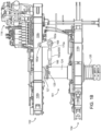
- Figure 1A illustrates an embodiment of a tong assembly 100 according to one embodiment of the present disclosure.
- Figure 1B is a schematic side view of the tong assembly 100.
- the tong assembly 100 includes a power tong 102 and a backup tong 104.
- the power tong 102 may be suspended from a handling tool or supported by a stand.
- the power tong 102 and the backup tong 104 may be connected by a load transfer assembly 161.
- the power tong 102 may include a frame 108 with a central opening 110 for receiving a tubular.
- the frame 108 may include two or more sections movable relative to each other to open and close the central opening 110.
- the frame 108 may include two front sections 108a, 108b and one back section 108c.
- the front sections 108a, 108b are connected to the back section 108c by hinges and pivotable about the back section 108c.
- the front sections 108a, 108b may be pivoted by pistons 109.
- the power tong 102 may further include a rotor 112 disposed in the frame 108.
- the rotor 112 may be a segmented rotor.
- the rotor 112 may be coupled to a motor assembly 114.
- Jaws 116 may be attached to an inner diameter of the rotor 112.
- the jaws 116 may rotate with the rotor 112 to rotate a tubular about a central axis 101 during makeup and breakout of a tubular connection.
- the jaws 116 may move radially relative to the frame 108 to secure and release a tubular or to accommodate tubulars of various diameters.
- the jaws 116 may be driven using a hydraulic circuit.
- the backup tong 104 may be disposed underneath the power tong 102.
- the backup tong 104 may include a frame 118 with a central opening 120 for receiving a tubular.
- the frame 118 may include two or more sections movable relative to each other to open and close the central opening 120.
- the frame 118 may include two front sections 118a, 118b and one back section 118c.
- the front sections 118a, 118b are connected to the back section 118c by hinges and pivotable about the back section 118c.
- the front sections 118a, 118b may be pivoted by pistons 119.
- the backup tong 104 may include jaws 122 attached to the frame 118.
- the jaws 122 may move radially relative to the frame 118 to secure and release a tubular or to accommodate tubular of various diameters.
- the jaws 122 may be driven using a hydraulic circuit.
- the frame 118 of the backup tong 104 may be movably coupled to support legs 124. Lower ends 125 of the support legs 124 are configured to stand a platform or other stationary planes. The support legs 124 support the backup tong 104 and prevent the backup tong 104 from rotating during operation.
- the frame 118 may have through openings for receiving the support legs 124 therein.
- the frame 118 may include sleeves 128 for receiving the support legs 124.
- the frame 118 may be coupled to two support legs 124 that are symmetrically positioned about a central axis 103 of the backup tong 104. The central axis 103 and central axis of the two support legs 124 may be within the same plane.
- Each support leg 124 may include a spring member 126 disposed at lower ends 125. Weight and vertical load of the backup tong 104 may rest on the spring members 126. The spring members 126 allow the backup tong 104 to be movable along the support legs 124 thus providing structure flexibility.
- the power tong 102 may include alignment posts 127 extending from a lower side of the frame 108.
- the alignment posts 127 may be inserted into the support legs 124 so that the central axis 101 of the power tong 102 and the central axis 103 of the backup tong 104 may be substantially aligned (see Figure 1C ).
- the inner diameter of the support legs 124 is substantially larger than the outer diameter of the alignment posts 127 so that the power tong 102 may move relative to the backup tong 104 within a limited range without the alignment posts 127 contacting the support legs 124.
- pins 129 may be used to couple the alignment posts 127 to the support leg 124. However, during operation, the pins 129 are removed to allow relative movements between the power tong 102 and the backup tong 104 and avoid transmission of load between the alignment posts 127 and the support legs 124.
- the power tong 102 and the backup tong 104 are connected through the load transfer assembly 161.
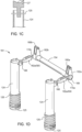
- the load transfer assembly 161 may include two arms 162a, 162b, two links 170a, 170b, and a torque bar 164, as illustrated in Figure 1D .
- the two arms 162a, 162b are coupled to the sides of the power tong 102 and extend downward from the power tong 102.
- the arms 162a, 162b may be pivotally coupled to the power tong 102 by pivot connections 180a, 180b, respectively.
- the pivot connections 180a, 180b may be located equidistant from the central axis 101.
- the torque bar 164 is connected to the two arms 162a, 162b.
- the links 170a, 170b are coupled between the support legs 124 and the arms 162a, 162b. Each link 170a, 170b is coupled to the corresponding support leg 124 by a pivot connection 166. Each link 170a, 170b is coupled to the corresponding arm 162a, 162b by a pivot connection 168.
- the load transfer assembly 161 coupled to the power tong 102 and the backup tong 104, provides reaction torques to prevent the power tong 102 from moving relative to the backup tong 104 along a horizontal plane.
- the torque applied by the power tong 102 creates a reaction force which, because of the torque bar 164 and the arms 162a, 162b, results in substantially equal and opposite movements being applied to the backup tong 104 via the links 170a, 170b.
- each arm 162a, 162b is coupled to a load cell 182a, 182b configured to measure the torque applied to the tubular connection.
- the load cells 182a, 182b may be integrated in the respective arm 162a, 162b.
- the load cells 182a, 182b may be attached to the respective arm 162a, 162b.
- the load cells 182a, 182b may be configured to measure data related to the force applied to a connection during makeup or breakout.
- the load cell 182a, 182b may be an electronic load cell.
- the load cell 182a, 182b may be configured to measure the applied force in tension or compression.
- the first load cell 182a may be configured to measure the applied force in tension during makeup, while the second load cell 182b is configured to measure the applied force in compression during makeup. During breakout, the second load cell 182b is configured to measure the applied force in tension, while the first load cell 182a is configured to measure the applied force in compression. It is contemplated the tong assembly 100 may include a single load cell, such as load cell 182a or load cell 182b.
- Figure 2 is a perspective view of a load cell 300.
- the load cell 300 is suitable for use as one or both of the load cells 182a, 182b of the tong assembly 100.
- Figure 3A is partial cross-sectional view of the load cell 300
- Figure 3B is a cross-sectional view of the load cell 300 shown along a longitudinal plane.
- the longitudinal plane extends through a longitudinal axis 302 that passes through the centers of eyes 311, 312 within body 310.
- the longitudinal axis 302 may describe the direction along which a tension or compression force may act or may primarily act when load cell 300 is operating.
- the load cell 300 includes a body 310 having two eyes 311, 312 for coupling to the tong assembly 100.
- Figure 3C is a cross-sectional view of the second eye 312 along a transverse plane relative to body axis 302.
- the body 310 may be manufactured by initially forming a cast body and then machining the body to refine it.
- a bearing 316 may be disposed in the first and second eyes 311, 312.
- a bearing retainer 317 may be disposed in a groove 318 on each side of the bearing 316 to keep the bearing 316 in position.
- Bearings 316 may define a ball joint having an inner race that can pivot in multiple directions relative to an outer race at body 310.
- a biasing member 320 is disposed around the second eye 312 on each side of the body 310.
- An exemplary biasing member 320 is a cup spring.
- the biasing member 320 may extend beyond an outer surface of the body 310.
- the biasing member 320 includes a hole in alignment with the second eye 312 for receiving the connector 313.
- Two spring retainers 322 are used to retain the biasing members 320 in position, although other suitable devices for retaining the biasing members 320 are contemplated.
- the spring retainers 322 may be attached to the body 310 using a screw, bolt, or other suitable attachment devices.
- the first eye 311 is pivotally connected to the torsion bar 164, and the second eye 312 is pivotally connected to a bracket 324 (shown in Figure 4 ) of the support leg 124.
- a connector 313, such as a pin or bolt, may be inserted through bracket 324 and the second eye 312 of the body 310 to form the pivot connection 366.
- the bracket 324 may have two flanges, and the second eye 312 is disposed between the flanges.
- a gap 337 may be disposed between one or both brackets 324 and load cell body 310, or between one or both brackets 324 and one or both biasing members 320.
- One or both biasing members 320 may extend beyond the body 310 and contact a bracket 324.
- One or both biasing members 320 may contact a bracket 324 and may be slightly compressed by a bracket 324 while load transfer assembly 161 is in a resting configuration.
- the body 310 includes a chamber 330 for receiving the one or more electronic components, such as a strain gauge 332, an electrical board 335, connection wires or cables, and other suitable electronic components for measuring and communicating the measured strain.
- the chamber 330 is disposed between the first eye 311 and the second eye 312.
- the chamber 330 is an aperture formed through the body 310.
- the upper and lower walls of the chamber 330 define upper and lower thin wall sections 333 in the body 310.
- the thin wall sections 333 are disposed between the first eye 311 and the second eye 312.
- Thin wall section 333 extends lengthwise generally in the direction of the body axis 302, extending towards eyes 311, 312.
- the thin wall sections 333 may be configured as upper and lower tension beams during measurements of strain.
- Figure 3D is a cross-sectional view of the chamber 330 along a transverse plane, relative to body axis 302.
- a recess 339 may be formed on the outer surface of the body to further reduce the thickness of the thin wall section 333.
- the thin wall sections 333 may define the smallest cross-sectional area in the transverse plane of the body 320.
- the cross-sectional area of the body 310 that includes the thin wall sections 333 is less than the cross-sectional area of the body 310 in other planes that are perpendicular to body axis 302 but not passing through chamber 330.
- the load cell 300 may include a plurality of strain gauges; for example, two strain gauges 332.
- one strain gauge 332 is disposed on the inner surface of the body 310 below the electrical board 335, and the other strain gauge 332 is disposed on the inner surface of the body 310 above the electrical board 335.
- the strain gauges 332 are disposed on the inner surface of the thin wall section 333.
- the strain gauges 332 may be disposed in a recess of the inner surface of the body 310.
- the strain gauges 332 are configured to measure a tension force or a compression force exert on load cell 300. In turn, the measured force may be used to calculate the applied torque.
- the electrical board 335 may extend across the chamber 330 and be disposed in a groove 336 formed in the inner surface of the body 310 and oriented along the longitudinal axis 302.
- the electrical board 335 includes amplifying electronic components.
- a channel 338 is formed in the body 310 for wired communication, such as via cable, between the electrical board 335 and a plug 340.
- the plug 340 is disposed at a flange portion 314 of the body 310.
- the flange portion 315 may also be described as a boss or a protrusion extending from the main portion of body 310.
- the flange portion 314 is offset from the portion of the thin wall sections 333 that hold strain gauges 332, so as not to influence the strain gauges 332 during strain event.
- the plug 340 facilitates connection between the load cell 300 with another electrical device.
- the wired communication may include data, power, or both.
- a metal plate 350 is used as a cover to enclose the chamber on each side of the body 310.
- the metal plates 350 may be attached to the body 310 using an airtight seal.
- a metal plate 350 may be glued to each side of the body 310.
- the metal plates 350 are elastically glued to the body to reduce the influence on the measurement.
- silicone or another suitable filling material may be provided in the chamber 330 to displace or to prevent an intrusion of air or other fluids. Air tightness can be checked by supplying pressurized air through the channel 338.
- the metal plates 350 may be attached to the body 310 independently from other components attached or disposed in the chamber 330, including but not limited to the strain gauges 332, the electrical board 335, and the electrical connection such as cable.
- the body 310 may include over-sized holes to receive fasteners to allow the plates 350 to move relative to the fasteners and the body 310.
- a seal element may be used seal between each plate and the chamber, making the fastener junction fluid-tight.
- Figure 4 shows the load cell 300 in alignment with the support leg 124 when in a resting configuration, e.g., before rotation of a tubular that is being made-up or broken-out.
- the body axis 302 of load cell 300 extends through or nearly through the center or the central region of support leg 124.
- the load cell 300 may be perpendicular to the support leg 124 in the cross-sectional view of Figure 4 .
- the biasing members 320 such as cup springs, are used to align the support leg 124 with the load cell 300 before, during, or after operation. The alignment is maintained during the initial rotations of the tubular when the torque is low.
- the friction at the backup tong 104 locks the support legs 124 against rotation about its vertical axis.
- the load cell 300 is allowed to rotate relative to the support leg 124 at the pivot connection 366 that includes the second eye 312.
- the springs 320 create a slight, acceptable bending at the load cell 300.
- the springs 320 will return the support leg 124 into alignment with the load cell 300, as shown in Figure 4 .
- FIG. 6 is a block diagram illustrating a tubular makeup system 200.
- the tubular makeup system 200 may include the tong assembly 100, a tong remote unit (TRU) 204, a turns counter 208, load cell 182a (such as load cell 300), and the control system 206.
- the control system 206 may communicate with the TRU 204 via an interface. Depending on sophistication of the TRU 204, the interface may be analog or digital. Alternatively, the control system 206 may also serve as the TRU.
- a programmable logic controller (PLC) 216 of the control system 206 may monitor the turns count signals 210 and torque signals 214a, 214b from the respective sensors 208, 182a, 182b and compare the measured values of these signals with predetermined values 223-230.
- the PLC 216 may be any type of embedded computer device, for example, the PLC 216 may be replaced by a microcontroller unit (MCU), field programmable gate array (FPGA), application specific integrated circuit (ASIC), application specific instruction set processor (ASIP), digital signal processor (DSP), etc.
- the predetermined values 223-230 may be input by a technician for a particular connection.
- the predetermined values 223-230 may be input to the PLC 216 via an input device 218, such as a keypad or any touch sensitive display.
- Illustrative predetermined values 223-230 which may be input, by a technician or otherwise, include minimum and maximum delta gradient values 223, a shoulder threshold gradient 224, a dump torque value 226, minimum and maximum delta turns values 228, minimum and maximum torque values 230, and reference curve data 242.
- various output may be observed by a technician on an output device, such as a video monitor, which may be one of a plurality of output devices 220.
- the plurality of output devices 220 may also include a printer, a plotter, an alarm, or other audio equipment.
- the PLC 216 may output a dump signal 222 to the TRU 204 to automatically shut down or reduce the torque exerted by the tong assembly 100.
- dump signal 222 may be issued in response to the measured torque value reaching the dump torque 226 and/or a bad connection.
- the comparison of measured turn count values and torque values with respect to predetermined values is performed by one or more functional units of the PLC 216.
- the functional units may generally be implemented as hardware, software or a combination thereof.
- the functional units may include one or more of a torque-turns plotter algorithm 232, a process monitor 234, a torque gradient calculator 236, a smoothing algorithm 238, a sampler 240, a database 242 of reference curves, a connection evaluator 252, and a target detector 254.
- the process monitor 234 may include one or more of a thread engagement detection algorithm 244, a seal detection algorithm 246, a shoulder detection algorithm 248, and a graphical evaluator algorithm 250.
- the functional units may be performed by a single unit. As such, the functional units may be considered logical representations, rather than well-defined and individually distinguishable components of software or hardware.
- one of the threaded members e.g., tubular 2 and coupling 6
- the applied torque and rotation are measured at regular intervals throughout the makeup.
- the load cell 330 will measure the tension force acting on the load cell 330. For example, if it is a makeup process, the load cell 330 will experience a tension force since the makeup torque is applied clockwise. In turn, the measured force may be used to calculate the applied torque by the control system 206 or TRU 204.
- the frequency with which torque and rotation are measured may be specified by the sampler 240.
- the sampler 240 may be configurable, so that a technician may input a desired sampling frequency.
- the torque and rotation values may be stored as a paired set in a buffer area of memory. Further, the rate of change of torque with respect to rotation (hereinafter "torque gradient") may be calculated for each paired set of measurements by the torque gradient calculator 236.
- the smoothing algorithm 238 may operate to smooth a torque-turns curve and/or a torque gradient curve (e.g., by way of a running average). These values (torque, rotation, and torque gradient) may then be plotted by the plotter 232 for display on the output device 220.
- the values may then be compared by the connection evaluator 252, either continuously or at selected events, with predetermined values, such as the values 223-230. Based on the comparison of the measured and/or calculated values with the predefined values 223-230, the process monitor 234 may determine the occurrence of various events and the connection evaluator 252 may determine whether to continue rotation or abort the makeup.
- the thread engagement detection algorithm 244 may monitor for thread engagement of the tubulars 2, 4. Upon detection of thread engagement a first marker is stored. The marker may be quantified, for example, by time, rotation, torque, the torque gradient, or a combination of any such quantifications. During continued rotation, the seal detection algorithm 246 monitors for the seal condition.
- This may be accomplished by comparing the calculated torque gradient with a predetermined threshold seal condition value.
- a second marker indicating the seal condition may be stored if/when the seal condition is detected.
- the torque value at the seal condition may be evaluated by the connection evaluator 252.
- a determination may be made as to whether the turns value and/or torque value are within specified limits.
- the specified limits may be predetermined, or based on a value measured during makeup. If the connection evaluator 252 determines a bad connection, rotation may be terminated. Otherwise, rotation continues and the shoulder detection algorithm 248 monitors for the shoulder position. This may be accomplished by comparing the calculated torque gradient with the shoulder threshold gradient 224. When the shoulder position is detected, a third marker indicating the shoulder position is stored. The connection evaluator 252 may then determine whether the torque value at the shoulder position is acceptable by comparing to the respective input torque values 230.
- a delta turns value may be entered instead of the dump torque 226.
- the target detector 254 may then calculate a target turns value using the shoulder turns and the delta turns value (target turns equals shoulder turns plus delta turns).
- a load cell for use with a tong assembly includes a body; a chamber formed in the body; a strain gauge disposed in the chamber; a first eye for pivotal coupling to the tong assembly; and a second eye for pivotal coupling to the tong assembly.
- a tubular handling apparatus includes a power tong; a backup tong; and a load transfer assembly connected between the power tong and the backup tong, wherein the load transfer assembly includes a load cell.
- the load cell includes a body; a chamber formed in the body; a strain gauge disposed in the chamber; a first eye for pivotal coupling to power tong; a second eye for pivotal coupling to backup tong; and optionally, a biasing member disposed around the second eye for biasing the body relative to the backup tong.
- a method of measuring a torque applied between a first tubular and a second tubular includes gripping the first tubular using a power tong; gripping the second tubular using a backup tong; applying a torque to the first tubular using a power tong; measuring the torque using a load cell; bending the load cell relative to the backup tong while measuring the torque; and returning the load cell into alignment with the backup tong using a biasing member.
- the load cell may include a biasing member disposed around the second eye for biasing the body relative to the tong assembly.
- the biasing member may include a hole in alignment with the second eye.
- the biasing member may extend beyond the body.
- the strain gauge may be disposed on a thin wall section of the body.
- the thin wall section of the body may define a portion of the chamber and is disposed between the first eye and the second eye.
- the load cell may include an external plug for data communication with the strain gauge.
- the load cell may include a channel formed in the body, the channel extending between the chamber and the plug.
- the load cell may include an electrical board disposed in the chamber and in communication with the strain gauge.
- the electrical board may be disposed in the chamber along a longitudinal axis of the body.
- a plurality of strain gauges may be disposed in the chamber.
- An electrical board may be positioned between two strain gauges.
- the load cell may include a bearing disposed in the second eye.
- the load cell may include a bearing retainer for retaining the bearing in the second eye.
- the load cell may include a plate for enclosing the chamber.
- the plate may be sealingly and elastically mounted to the body.
- the plate may be glued to the body.
- a silicone may be disposed in the chamber.
- the load cell may include a retainer for retaining the biasing member on the body.
- the biasing member may be attached to a body of the load cell.
- the body may be formed from a cast.
- the body may be machined after removal from a cast.
- the biasing member may be disposed around an eye formed at one end of a body of the load cell.
Landscapes
- Engineering & Computer Science (AREA)
- Geology (AREA)
- Mining & Mineral Resources (AREA)
- Life Sciences & Earth Sciences (AREA)
- Physics & Mathematics (AREA)
- General Life Sciences & Earth Sciences (AREA)
- Mechanical Engineering (AREA)
- Fluid Mechanics (AREA)
- Environmental & Geological Engineering (AREA)
- Geochemistry & Mineralogy (AREA)
- General Physics & Mathematics (AREA)
- Force Measurement Appropriate To Specific Purposes (AREA)
- Measurement Of Force In General (AREA)
- Fuel Cell (AREA)
- Manipulator (AREA)
Abstract
Description
- The present disclosure generally relates to methods and apparatus for making up and breaking out tubular connections.
- Construction of oil or gas wells usually requires making long tubular strings that makeup casing, risers, drill pipe or other tubing. Due to the length of these strings, sections or stands of tubulars are progressively added to or removed from the tubular strings as they are lowered or raised from a drilling platform. A tong assembly is commonly used to makeup or breakout joints in the tubular strings.
- It is desirable that the tong assembly applies a predetermined torque to the joint to prevent the joint from being too loose or too tight. Torque applied to the tubular has been monitored by measuring a force of compression or tension exerted on a component of a tong assembly and converting the measured force to torque. A tong assembly may be equipped with a load cell to measure the torque applied to a tubular connection.
- The various conventional load cells are expensive to manufacture due to use of complex parts, considerable amount of machining, and difficulty in assembly.
- Therefore, there is a need for an improved load cell for a tong assembly.
- Described is a load cell for use with a tong assembly includes a body; a chamber formed in the body; and a strain gauge disposed in the chamber. The load cell also includes a first eye for pivotal coupling to the tong assembly, and a second eye for pivotal coupling to the tong assembly. An optional biasing member is disposed around the second eye for biasing the body relative to the tong assembly.
- In one embodiment, a tubular handling apparatus includes a power tong; a backup tong; and a load transfer assembly connected between the power tong and the backup tong. The load transfer assembly may include a load cell. In one embodiment, a load cell for use with a tong assembly includes a body; a chamber formed in the body; and a strain gauge disposed in the chamber. The load cell also includes a first eye for pivotal coupling to the tong assembly, and a second eye for pivotal coupling to the tong assembly. An optional biasing member is disposed around the second eye for biasing the body relative to the tong assembly.
- Further described is a method of measuring a torque applied between a first tubular and a second tubular includes gripping the first tubular using a power tong; gripping the second tubular using a backup tong; applying a torque to the first tubular using a power tong; and measuring the torque using a load cell. The load cell may be bent relative to the backup tong while measuring the torque. The load cell may be returned into alignment with the backup tong using a biasing member.
- So that the manner in which the above recited features of the present disclosure can be understood in detail, a more particular description of the disclosure, briefly summarized above, may be had by reference to embodiments, some of which are illustrated in the appended drawings. It is to be noted, however, that the appended drawings illustrate only typical embodiments of this disclosure and are therefore not to be considered limiting of its scope, for the disclosure may admit to other equally effective embodiments.
-
Figure 1A is a perspective view of a tong assembly according to one embodiment of the present disclosure. -
Figure 1B is a side view of the tong assembly ofFigure 1A . -
Figure 1C is a schematic partial sectional view of a support leg of the tong assembly ofFigure 1A . -
Figure 1D schematically illustrates a load transfer assembly of the tong assembly ofFigure 1A . -
Figure 2 is a perspective view of a load cell. -
Figure 3A is partial cross-sectional view of the load cell ofFigure 2 . -
Figure 3B is a cross-sectional view of the load cell ofFigure 2 . -
Figure 3C is a cross-sectional view of the second eye of the load cell ofFigure 2 . -
Figure 3D is a cross-sectional view of the chamber of the load cell ofFigure 2 . -
Figure 4 is a cross-sectional view of the load cell ofFigure 2 showing the load cell in alignment with the support leg of a tong assembly. -
Figure 5 is a top view of the load cell ofFigure 2 showing the load cell in a bent position relative to the support leg of a tong assembly. -
Figure 6 is a block diagram illustrating a tubular makeup system. - The present disclosure generally relates to a tong assembly for making up and breaking out a tubular connection such as a connection between two tubulars in a tubular string. The tubular strings may be made of tubulars that form risers, casings, drill pipes or other tubulars in oil and gas wells. Embodiment of the present disclosures relates to a tong assembly having a power tong, a backup tong and a load transfer assembly connected between the power tong and the backup tong. The load transfer assembly includes a torque bar and sensors, such as load cells, to monitor the torque exerted on the tubular string by the tong assembly.
-
Figure 1A illustrates an embodiment of atong assembly 100 according to one embodiment of the present disclosure.Figure 1B is a schematic side view of thetong assembly 100. Thetong assembly 100 includes apower tong 102 and abackup tong 104. In operation, thepower tong 102 may be suspended from a handling tool or supported by a stand. Thepower tong 102 and thebackup tong 104 may be connected by aload transfer assembly 161. - The
power tong 102 may include aframe 108 with acentral opening 110 for receiving a tubular. Theframe 108 may include two or more sections movable relative to each other to open and close thecentral opening 110. Theframe 108 may include twofront sections back section 108c. Thefront sections back section 108c by hinges and pivotable about theback section 108c. Thefront sections pistons 109. - The
power tong 102 may further include arotor 112 disposed in theframe 108. Therotor 112 may be a segmented rotor. Therotor 112 may be coupled to amotor assembly 114.Jaws 116 may be attached to an inner diameter of therotor 112. Thejaws 116 may rotate with therotor 112 to rotate a tubular about acentral axis 101 during makeup and breakout of a tubular connection. Thejaws 116 may move radially relative to theframe 108 to secure and release a tubular or to accommodate tubulars of various diameters. Thejaws 116 may be driven using a hydraulic circuit. - The
backup tong 104 may be disposed underneath thepower tong 102. Thebackup tong 104 may include aframe 118 with acentral opening 120 for receiving a tubular. Theframe 118 may include two or more sections movable relative to each other to open and close thecentral opening 120. Theframe 118 may include twofront sections back section 118c. Thefront sections back section 118c by hinges and pivotable about theback section 118c. Thefront sections pistons 119. Thebackup tong 104 may includejaws 122 attached to theframe 118. Thejaws 122 may move radially relative to theframe 118 to secure and release a tubular or to accommodate tubular of various diameters. Thejaws 122 may be driven using a hydraulic circuit. - The
frame 118 of thebackup tong 104 may be movably coupled to supportlegs 124. Lower ends 125 of thesupport legs 124 are configured to stand a platform or other stationary planes. Thesupport legs 124 support thebackup tong 104 and prevent thebackup tong 104 from rotating during operation. Theframe 118 may have through openings for receiving thesupport legs 124 therein. Theframe 118 may includesleeves 128 for receiving thesupport legs 124. Theframe 118 may be coupled to twosupport legs 124 that are symmetrically positioned about acentral axis 103 of thebackup tong 104. Thecentral axis 103 and central axis of the twosupport legs 124 may be within the same plane. Eachsupport leg 124 may include aspring member 126 disposed at lower ends 125. Weight and vertical load of thebackup tong 104 may rest on thespring members 126. Thespring members 126 allow thebackup tong 104 to be movable along thesupport legs 124 thus providing structure flexibility. - The
power tong 102 may includealignment posts 127 extending from a lower side of theframe 108. When thetong assembly 100 is assembled, the alignment posts 127 may be inserted into thesupport legs 124 so that thecentral axis 101 of thepower tong 102 and thecentral axis 103 of thebackup tong 104 may be substantially aligned (seeFigure 1C ). The inner diameter of thesupport legs 124 is substantially larger than the outer diameter of the alignment posts 127 so that thepower tong 102 may move relative to thebackup tong 104 within a limited range without the alignment posts 127 contacting thesupport legs 124. When the alignment posts 127 do not contact thesupport legs 124, torsion and force are not transmitted between thesupport legs 124 and the alignment posts 127. During assembly or transportation, pins 129 may be used to couple the alignment posts 127 to thesupport leg 124. However, during operation, thepins 129 are removed to allow relative movements between thepower tong 102 and thebackup tong 104 and avoid transmission of load between the alignment posts 127 and thesupport legs 124. - The
power tong 102 and thebackup tong 104 are connected through theload transfer assembly 161. Theload transfer assembly 161 may include twoarms links torque bar 164, as illustrated inFigure 1D . The twoarms power tong 102 and extend downward from thepower tong 102. Thearms power tong 102 bypivot connections pivot connections central axis 101. Thetorque bar 164 is connected to the twoarms links support legs 124 and thearms link corresponding support leg 124 by apivot connection 166. Eachlink corresponding arm pivot connection 168. - When
power tong 102 applies a torque to rotate a first tubular causing a joint between the first tubular and a second tubular held by thebackup tong 104 to tighten or loosen, theload transfer assembly 161, coupled to thepower tong 102 and thebackup tong 104, provides reaction torques to prevent thepower tong 102 from moving relative to thebackup tong 104 along a horizontal plane. For example, during makeup, the torque applied by thepower tong 102 creates a reaction force which, because of thetorque bar 164 and thearms backup tong 104 via thelinks - Referring to
Figure 1D , eacharm load cell load cells respective arm load cells respective arm load cells load cell load cell first load cell 182a may be configured to measure the applied force in tension during makeup, while thesecond load cell 182b is configured to measure the applied force in compression during makeup. During breakout, thesecond load cell 182b is configured to measure the applied force in tension, while thefirst load cell 182a is configured to measure the applied force in compression. It is contemplated thetong assembly 100 may include a single load cell, such asload cell 182a orload cell 182b. -
Figure 2 is a perspective view of aload cell 300. Theload cell 300 is suitable for use as one or both of theload cells tong assembly 100.Figure 3A is partial cross-sectional view of theload cell 300, andFigure 3B is a cross-sectional view of theload cell 300 shown along a longitudinal plane. InFigure 3B , the longitudinal plane extends through alongitudinal axis 302 that passes through the centers ofeyes body 310. Thelongitudinal axis 302 may describe the direction along which a tension or compression force may act or may primarily act whenload cell 300 is operating. Theload cell 300 includes abody 310 having twoeyes tong assembly 100.Figure 3C is a cross-sectional view of thesecond eye 312 along a transverse plane relative tobody axis 302. Thebody 310 may be manufactured by initially forming a cast body and then machining the body to refine it. A bearing 316 may be disposed in the first andsecond eyes retainer 317 may be disposed in agroove 318 on each side of thebearing 316 to keep the bearing 316 in position.Bearings 316 may define a ball joint having an inner race that can pivot in multiple directions relative to an outer race atbody 310. A biasingmember 320 is disposed around thesecond eye 312 on each side of thebody 310. Anexemplary biasing member 320 is a cup spring. The biasingmember 320 may extend beyond an outer surface of thebody 310. In one example, the biasingmember 320 includes a hole in alignment with thesecond eye 312 for receiving theconnector 313. Twospring retainers 322 are used to retain the biasingmembers 320 in position, although other suitable devices for retaining the biasingmembers 320 are contemplated. Thespring retainers 322 may be attached to thebody 310 using a screw, bolt, or other suitable attachment devices. - Referring to
Figure 1D andFigure 4 , when assembled in theload transfer assembly 161, thefirst eye 311 is pivotally connected to thetorsion bar 164, and thesecond eye 312 is pivotally connected to a bracket 324 (shown inFigure 4 ) of thesupport leg 124. Aconnector 313, such as a pin or bolt, may be inserted throughbracket 324 and thesecond eye 312 of thebody 310 to form thepivot connection 366. Thebracket 324 may have two flanges, and thesecond eye 312 is disposed between the flanges. Agap 337 may be disposed between one or bothbrackets 324 andload cell body 310, or between one or bothbrackets 324 and one or both biasingmembers 320. One or both biasingmembers 320 may extend beyond thebody 310 and contact abracket 324. One or both biasingmembers 320 may contact abracket 324 and may be slightly compressed by abracket 324 whileload transfer assembly 161 is in a resting configuration. - Referring again to
Figure 3B , thebody 310 includes achamber 330 for receiving the one or more electronic components, such as astrain gauge 332, anelectrical board 335, connection wires or cables, and other suitable electronic components for measuring and communicating the measured strain. Thechamber 330 is disposed between thefirst eye 311 and thesecond eye 312. In the example as shown, thechamber 330 is an aperture formed through thebody 310. In this respect, the upper and lower walls of thechamber 330 define upper and lowerthin wall sections 333 in thebody 310. Thethin wall sections 333 are disposed between thefirst eye 311 and thesecond eye 312.Thin wall section 333 extends lengthwise generally in the direction of thebody axis 302, extending towardseyes thin wall sections 333 may be configured as upper and lower tension beams during measurements of strain.Figure 3D is a cross-sectional view of thechamber 330 along a transverse plane, relative tobody axis 302. In one example, arecess 339 may be formed on the outer surface of the body to further reduce the thickness of thethin wall section 333. Thethin wall sections 333 may define the smallest cross-sectional area in the transverse plane of thebody 320. The cross-sectional area of thebody 310 that includes thethin wall sections 333 is less than the cross-sectional area of thebody 310 in other planes that are perpendicular tobody axis 302 but not passing throughchamber 330. - The
load cell 300 may include a plurality of strain gauges; for example, twostrain gauges 332. In one example, onestrain gauge 332 is disposed on the inner surface of thebody 310 below theelectrical board 335, and theother strain gauge 332 is disposed on the inner surface of thebody 310 above theelectrical board 335. In this example, the strain gauges 332 are disposed on the inner surface of thethin wall section 333. The strain gauges 332 may be disposed in a recess of the inner surface of thebody 310. The strain gauges 332 are configured to measure a tension force or a compression force exert onload cell 300. In turn, the measured force may be used to calculate the applied torque. Theelectrical board 335 may extend across thechamber 330 and be disposed in agroove 336 formed in the inner surface of thebody 310 and oriented along thelongitudinal axis 302. In one example, theelectrical board 335 includes amplifying electronic components. - A
channel 338 is formed in thebody 310 for wired communication, such as via cable, between theelectrical board 335 and aplug 340. Theplug 340 is disposed at aflange portion 314 of thebody 310. The flange portion 315 may also be described as a boss or a protrusion extending from the main portion ofbody 310. Theflange portion 314 is offset from the portion of thethin wall sections 333 that holdstrain gauges 332, so as not to influence the strain gauges 332 during strain event. Theplug 340 facilitates connection between theload cell 300 with another electrical device. The wired communication may include data, power, or both. Ametal plate 350 is used as a cover to enclose the chamber on each side of thebody 310. Themetal plates 350 may be attached to thebody 310 using an airtight seal. Ametal plate 350 may be glued to each side of thebody 310. In one example, themetal plates 350 are elastically glued to the body to reduce the influence on the measurement. Optionally, silicone or another suitable filling material may be provided in thechamber 330 to displace or to prevent an intrusion of air or other fluids. Air tightness can be checked by supplying pressurized air through thechannel 338. Themetal plates 350 may be attached to thebody 310 independently from other components attached or disposed in thechamber 330, including but not limited to the strain gauges 332, theelectrical board 335, and the electrical connection such as cable. As a result, components such as the strain gauges 332, theelectrical board 335, and the electrical connections can be installed independently of thecover plates 350. Thebody 310 may include over-sized holes to receive fasteners to allow theplates 350 to move relative to the fasteners and thebody 310. A seal element may be used seal between each plate and the chamber, making the fastener junction fluid-tight. - As introduced earlier,
Figure 4 shows theload cell 300 in alignment with thesupport leg 124 when in a resting configuration, e.g., before rotation of a tubular that is being made-up or broken-out. In this aligned position, thebody axis 302 ofload cell 300 extends through or nearly through the center or the central region ofsupport leg 124. Thus, when aligned, theload cell 300 may be perpendicular to thesupport leg 124 in the cross-sectional view ofFigure 4 . The biasingmembers 320, such as cup springs, are used to align thesupport leg 124 with theload cell 300 before, during, or after operation. The alignment is maintained during the initial rotations of the tubular when the torque is low. At higher torques, the friction at thebackup tong 104 locks thesupport legs 124 against rotation about its vertical axis. Referring toFigure 5 , theload cell 300 is allowed to rotate relative to thesupport leg 124 at thepivot connection 366 that includes thesecond eye 312. When compressed as shown, thesprings 320 create a slight, acceptable bending at theload cell 300. When the torque is lowered, thesprings 320 will return thesupport leg 124 into alignment with theload cell 300, as shown inFigure 4 . -
Figure 6 is a block diagram illustrating atubular makeup system 200. Thetubular makeup system 200 may include thetong assembly 100, a tong remote unit (TRU) 204, aturns counter 208,load cell 182a (such as load cell 300), and thecontrol system 206. Thecontrol system 206 may communicate with theTRU 204 via an interface. Depending on sophistication of theTRU 204, the interface may be analog or digital. Alternatively, thecontrol system 206 may also serve as the TRU. - A programmable logic controller (PLC) 216 of the
control system 206 may monitor the turns countsignals 210 andtorque signals respective sensors PLC 216 may be any type of embedded computer device, for example, thePLC 216 may be replaced by a microcontroller unit (MCU), field programmable gate array (FPGA), application specific integrated circuit (ASIC), application specific instruction set processor (ASIP), digital signal processor (DSP), etc. The predetermined values 223-230 may be input by a technician for a particular connection. The predetermined values 223-230 may be input to thePLC 216 via aninput device 218, such as a keypad or any touch sensitive display. - Illustrative predetermined values 223-230 which may be input, by a technician or otherwise, include minimum and maximum delta gradient values 223, a
shoulder threshold gradient 224, adump torque value 226, minimum and maximum delta turnsvalues 228, minimum andmaximum torque values 230, andreference curve data 242. During makeup of the connection 1, various output may be observed by a technician on an output device, such as a video monitor, which may be one of a plurality ofoutput devices 220. The plurality ofoutput devices 220 may also include a printer, a plotter, an alarm, or other audio equipment. - Upon the occurrence of a predefined event(s), the
PLC 216 may output adump signal 222 to theTRU 204 to automatically shut down or reduce the torque exerted by thetong assembly 100. For example,dump signal 222 may be issued in response to the measured torque value reaching thedump torque 226 and/or a bad connection. - The comparison of measured turn count values and torque values with respect to predetermined values is performed by one or more functional units of the
PLC 216. The functional units may generally be implemented as hardware, software or a combination thereof. The functional units may include one or more of a torque-turnsplotter algorithm 232, aprocess monitor 234, atorque gradient calculator 236, asmoothing algorithm 238, asampler 240, adatabase 242 of reference curves, aconnection evaluator 252, and atarget detector 254. The process monitor 234 may include one or more of a threadengagement detection algorithm 244, aseal detection algorithm 246, ashoulder detection algorithm 248, and agraphical evaluator algorithm 250. Alternatively, the functional units may be performed by a single unit. As such, the functional units may be considered logical representations, rather than well-defined and individually distinguishable components of software or hardware. - In operation, one of the threaded members (e.g., tubular 2 and coupling 6) is rotated by the
power tong 102 while the other tubular 4 is held by thebackup tong 104. The applied torque and rotation are measured at regular intervals throughout the makeup. Theload cell 330 will measure the tension force acting on theload cell 330. For example, if it is a makeup process, theload cell 330 will experience a tension force since the makeup torque is applied clockwise. In turn, the measured force may be used to calculate the applied torque by thecontrol system 206 orTRU 204. - The frequency with which torque and rotation are measured may be specified by the
sampler 240. Thesampler 240 may be configurable, so that a technician may input a desired sampling frequency. The torque and rotation values may be stored as a paired set in a buffer area of memory. Further, the rate of change of torque with respect to rotation (hereinafter "torque gradient") may be calculated for each paired set of measurements by thetorque gradient calculator 236. The smoothingalgorithm 238 may operate to smooth a torque-turns curve and/or a torque gradient curve (e.g., by way of a running average). These values (torque, rotation, and torque gradient) may then be plotted by theplotter 232 for display on theoutput device 220. - The values (torque, rotation, and torque gradient) may then be compared by the
connection evaluator 252, either continuously or at selected events, with predetermined values, such as the values 223-230. Based on the comparison of the measured and/or calculated values with the predefined values 223-230, the process monitor 234 may determine the occurrence of various events and theconnection evaluator 252 may determine whether to continue rotation or abort the makeup. The threadengagement detection algorithm 244 may monitor for thread engagement of thetubulars 2, 4. Upon detection of thread engagement a first marker is stored. The marker may be quantified, for example, by time, rotation, torque, the torque gradient, or a combination of any such quantifications. During continued rotation, theseal detection algorithm 246 monitors for the seal condition. This may be accomplished by comparing the calculated torque gradient with a predetermined threshold seal condition value. A second marker indicating the seal condition may be stored if/when the seal condition is detected. At this point, the torque value at the seal condition may be evaluated by theconnection evaluator 252. - For example, a determination may be made as to whether the turns value and/or torque value are within specified limits. The specified limits may be predetermined, or based on a value measured during makeup. If the
connection evaluator 252 determines a bad connection, rotation may be terminated. Otherwise, rotation continues and theshoulder detection algorithm 248 monitors for the shoulder position. This may be accomplished by comparing the calculated torque gradient with theshoulder threshold gradient 224. When the shoulder position is detected, a third marker indicating the shoulder position is stored. Theconnection evaluator 252 may then determine whether the torque value at the shoulder position is acceptable by comparing to the respective input torque values 230. - Alternatively, a delta turns value may be entered instead of the
dump torque 226. Thetarget detector 254 may then calculate a target turns value using the shoulder turns and the delta turns value (target turns equals shoulder turns plus delta turns). - In a described example, a load cell for use with a tong assembly includes a body; a chamber formed in the body; a strain gauge disposed in the chamber; a first eye for pivotal coupling to the tong assembly; and a second eye for pivotal coupling to the tong assembly.
- In an embodiment of the present invention, a tubular handling apparatus includes a power tong; a backup tong; and a load transfer assembly connected between the power tong and the backup tong, wherein the load transfer assembly includes a load cell. The load cell includes a body; a chamber formed in the body; a strain gauge disposed in the chamber; a first eye for pivotal coupling to power tong; a second eye for pivotal coupling to backup tong; and optionally, a biasing member disposed around the second eye for biasing the body relative to the backup tong.
- In another described example, a method of measuring a torque applied between a first tubular and a second tubular includes gripping the first tubular using a power tong; gripping the second tubular using a backup tong; applying a torque to the first tubular using a power tong; measuring the torque using a load cell; bending the load cell relative to the backup tong while measuring the torque; and returning the load cell into alignment with the backup tong using a biasing member.
- The load cell may include a biasing member disposed around the second eye for biasing the body relative to the tong assembly.
- The biasing member may include a hole in alignment with the second eye.
- The biasing member may extend beyond the body.
- The strain gauge may be disposed on a thin wall section of the body.
- The thin wall section of the body may define a portion of the chamber and is disposed between the first eye and the second eye.
- The load cell may include an external plug for data communication with the strain gauge.
- The load cell may include a channel formed in the body, the channel extending between the chamber and the plug.
- The load cell may include an electrical board disposed in the chamber and in communication with the strain gauge.
- The electrical board may be disposed in the chamber along a longitudinal axis of the body.
- A plurality of strain gauges may be disposed in the chamber.
- An electrical board may be positioned between two strain gauges.
- The load cell may include a bearing disposed in the second eye.
- The load cell may include a bearing retainer for retaining the bearing in the second eye.
- The load cell may include a plate for enclosing the chamber.
- The plate may be sealingly and elastically mounted to the body.
- The plate may be glued to the body.
- A silicone may be disposed in the chamber.
- The load cell may include a retainer for retaining the biasing member on the body.
- The biasing member may be attached to a body of the load cell.
- The body may be formed from a cast.
- The body may be machined after removal from a cast.
- The biasing member may be disposed around an eye formed at one end of a body of the load cell.
Claims (15)
- A tubular handling apparatus, comprising:a power tong (102);a backup tong (104); anda load transfer assembly (161) connected between the power tong (102) and the backup tong (104), wherein the load transfer (161) assembly includes a load cell (182a, 182b, 300), the load cell (182a, 182b, 300) having:a body (310);a chamber (330) formed in the body (310);a strain gauge (332) disposed in the chamber (330);a first eye (311) for pivotal coupling to power tong (102);a second eye (312) for pivotal coupling to backup tong (104); anda biasing member (320) disposed around the second eye (312) for biasing the body (310) relative to the backup tong (104).
- The tubular handling apparatus according to claim 1, wherein the biasing member (320) of the load cell (182a, 182b, 300) includes a hole in alignment with the second eye (320).
- The tubular handling apparatus according to claims 1 or 2, wherein the biasing member (320) of the load cell (182a, 182b, 300) extends beyond the body (310).
- The tubular handling apparatus according to any one of claims 1 to 3, further comprising a retainer (322) for retaining the biasing member (320) of the load cell (182a, 182b, 300) on the body (310).
- The tubular handling apparatus according to any preceding claim, further comprising a plate (350) for enclosing the chamber (330) of the load cell (182a, 182b, 300).
- The tubular handling apparatus according to claim 5, wherein the plate (350) is sealingly and elastically mounted to the body of the load cell (182a, 182b, 300).
- The tubular handling apparatus according to any preceding claim, further comprising a silicone disposed in the chamber (330) of the load cell (182a, 182b, 300).
- The tubular handling apparatus according to any preceding claim, wherein the strain gauge (332) is disposed on a thin wall section (333) of the body (310) of the load cell (182a, 182b, 300).
- The tubular handing apparatus of claim 8, wherein the thin wall section (333) of the body (310) defines a portion of the chamber (330) and is disposed between the first eye (311) and the second eye (312).
- The tubular handling apparatus according to any preceding claim, further comprising an external plug (340) for data communication with the strain gauge (332) of the load cell (182a, 182b, 300).
- The tubular handling apparatus according to claim 10, further comprising a channel (338) formed in the body of the load cell (182a, 182b, 300), the channel extending between the chamber (330) and the plug (340).
- The tubular handling apparatus according to any preceding claim, further comprising an electrical board (335) disposed in the chamber of the load cell (182a, 182b, 300), and in communication with the strain gauge (332).
- The tubular handling apparatus according to claim 12, wherein the electrical board (335) is disposed in the chamber (330) along a longitudinal axis (302) of the body (310) of the load cell (182a, 182b, 300).
- The tubular handling apparatus according to any preceding claim, further comprising a bearing (316) disposed in the second eye (312) of the load cell (182a, 182b, 300).
- The tubular handling apparatus according to any claim 14, further comprising a bearing retainer (317) for retaining the bearing (316) in the second eye (312).
Applications Claiming Priority (3)
| Application Number | Priority Date | Filing Date | Title |
|---|---|---|---|
| US16/855,492 US11136838B1 (en) | 2020-04-22 | 2020-04-22 | Load cell for a tong assembly |
| EP21724899.6A EP4139557B1 (en) | 2020-04-22 | 2021-04-20 | Load cell for a tong assembly |
| PCT/US2021/028231 WO2021216601A1 (en) | 2020-04-22 | 2021-04-20 | Load cell for a tong assembly |
Related Parent Applications (1)
| Application Number | Title | Priority Date | Filing Date |
|---|---|---|---|
| EP21724899.6A Division EP4139557B1 (en) | 2020-04-22 | 2021-04-20 | Load cell for a tong assembly |
Publications (2)
| Publication Number | Publication Date |
|---|---|
| EP4317929A2 true EP4317929A2 (en) | 2024-02-07 |
| EP4317929A3 EP4317929A3 (en) | 2024-04-03 |
Family
ID=75888222
Family Applications (2)
| Application Number | Title | Priority Date | Filing Date |
|---|---|---|---|
| EP21724899.6A Active EP4139557B1 (en) | 2020-04-22 | 2021-04-20 | Load cell for a tong assembly |
| EP23217144.7A Withdrawn EP4317929A3 (en) | 2020-04-22 | 2021-04-20 | Tubular handling apparatus |
Family Applications Before (1)
| Application Number | Title | Priority Date | Filing Date |
|---|---|---|---|
| EP21724899.6A Active EP4139557B1 (en) | 2020-04-22 | 2021-04-20 | Load cell for a tong assembly |
Country Status (7)
| Country | Link |
|---|---|
| US (1) | US11136838B1 (en) |
| EP (2) | EP4139557B1 (en) |
| AU (1) | AU2021260873A1 (en) |
| BR (1) | BR112022019017B1 (en) |
| CA (1) | CA3171951A1 (en) |
| MX (1) | MX2022011675A (en) |
| WO (1) | WO2021216601A1 (en) |
Families Citing this family (2)
| Publication number | Priority date | Publication date | Assignee | Title |
|---|---|---|---|---|
| US11506045B2 (en) * | 2019-06-11 | 2022-11-22 | Noven, Inc. | Two-point polished rod load-sensing system |
| US20260078646A1 (en) * | 2024-09-18 | 2026-03-19 | Weatherford Technology Holdings, Llc | Tong assembly position adjustment for threaded connection alignment |
Family Cites Families (45)
| Publication number | Priority date | Publication date | Assignee | Title |
|---|---|---|---|---|
| US2645121A (en) * | 1949-04-29 | 1953-07-14 | Byron Jackson Co | Weight sensing device |
| US3602866A (en) * | 1968-12-18 | 1971-08-31 | Erwin J Saxl | Force transducer |
| US4253696A (en) * | 1980-02-07 | 1981-03-03 | Bradley Lifting Corp. | Motorized lever-action vertical axis coil grab |
| US4738145A (en) | 1982-06-01 | 1988-04-19 | Tubular Make-Up Specialists, Inc. | Monitoring torque in tubular goods |
| USRE34063E (en) | 1982-06-01 | 1992-09-15 | Monitoring torque in tubular goods | |
| US4488611A (en) * | 1982-08-23 | 1984-12-18 | Revere Corporation Of America | Load cell |
| US4567779A (en) * | 1984-03-30 | 1986-02-04 | Analog Data Systems, Inc. | Method and apparatus for torque monitoring |
| US4649777A (en) | 1984-06-21 | 1987-03-17 | David Buck | Back-up power tongs |
| USRE33526E (en) | 1984-07-10 | 1991-01-29 | Bilco Tools, Inc. | Power tongs and control system |
| GB8901918D0 (en) | 1989-01-28 | 1989-03-15 | Franks Casing Crews Uk Limited | Control system |
| US4957002A (en) * | 1989-02-27 | 1990-09-18 | Bilco Tools, Inc. | Method, system and device for determining quality of assembly of tool parts |
| US5245877A (en) * | 1991-03-12 | 1993-09-21 | Weatherford U.S., Inc. | Tong load cell assembly |
| US5199518A (en) * | 1992-02-19 | 1993-04-06 | Sheldon Woodle | Load cell |
| WO1993022640A1 (en) * | 1992-05-01 | 1993-11-11 | Terry Hall | A system for measuring the torque applied to a threaded connection between sections of oilfield pipe |
| GB9212723D0 (en) * | 1992-06-16 | 1992-07-29 | Weatherford Lamb | Apparatus for connecting and disconnecting threaded members |
| US5542318A (en) | 1994-04-28 | 1996-08-06 | Wesch, Jr.; William E. | Bi-directional gripping apparatus |
| US5845549A (en) | 1995-12-20 | 1998-12-08 | Frank's Casing Crew And Rental Tools, Inc. | Power tong gripping ring mechanism |
| US6082224A (en) | 1997-01-29 | 2000-07-04 | Weatherford/Lamb, Inc. | Power tong |
| CA2269393C (en) | 1999-04-21 | 2008-02-12 | Universe Machine Corporation | Power tong and backup tong system |
| US6538576B1 (en) * | 1999-04-23 | 2003-03-25 | Halliburton Energy Services, Inc. | Self-contained downhole sensor and method of placing and interrogating same |
| US6212763B1 (en) | 1999-06-29 | 2001-04-10 | Frederic M. Newman | Torque-turn system for a three-element sucker rod joint |
| US7296623B2 (en) | 2000-04-17 | 2007-11-20 | Weatherford/Lamb, Inc. | Methods and apparatus for applying torque and rotation to connections |
| US7568522B2 (en) | 2001-05-17 | 2009-08-04 | Weatherford/Lamb, Inc. | System and method for deflection compensation in power drive system for connection of tubulars |
| WO2004079148A2 (en) | 2003-03-05 | 2004-09-16 | Weatherford/Lamb, Inc. | Tong |
| US7413398B2 (en) | 2003-04-01 | 2008-08-19 | Mccoy Corporation | Power tong positioner |
| AU2003282468A1 (en) | 2003-10-09 | 2005-05-26 | Varco I/P, Inc. | Make-up control system for tubulars |
| US7188547B1 (en) | 2005-12-23 | 2007-03-13 | Varco I/P, Inc. | Tubular connect/disconnect apparatus |
| NO327993B1 (en) * | 2006-06-09 | 2009-11-02 | Aker Mh As | Tang Construction |
| WO2008068391A1 (en) | 2006-12-07 | 2008-06-12 | Tractel S.A.S. | Electronic dynamometer |
| EP2288783B1 (en) | 2008-04-25 | 2016-02-17 | Weatherford Technology Holdings, LLC | Method of controlling torque applied to a tubular connection |
| CA2741532C (en) | 2008-10-22 | 2014-01-28 | Frank's International, Inc. | External grip tubular running tool |
| CA2984320C (en) | 2008-11-28 | 2019-09-03 | Key Energy Services, Inc. | Method and system for controlling tongs make-up speed and evaluating and controlling torque at the tongs |
| CA2686660C (en) | 2008-11-28 | 2018-06-19 | Key Energy Services, Inc. | Method and system for monitoring the efficiency and health of a hydraulically driven system |
| WO2011017610A1 (en) | 2009-08-06 | 2011-02-10 | Frank's International, Inc. | Tubular joining apparatus |
| US20120323500A1 (en) | 2011-06-20 | 2012-12-20 | Alberta Custom Technologies Ltd. | Apparatuses for monitoring power tong operation |
| US8726743B2 (en) | 2011-06-22 | 2014-05-20 | Weatherford/Lamb, Inc. | Shoulder yielding detection during tubular makeup |
| WO2015050931A1 (en) | 2013-10-01 | 2015-04-09 | Nabors Corporate Services | Automated roughneck |
| DE102014210860A1 (en) | 2014-06-06 | 2015-12-17 | Bentec Gmbh Drilling & Oilfield Systems | Method of operating a tong system for use on a drilling rig and corresponding tong system |
| US10392879B2 (en) * | 2015-05-28 | 2019-08-27 | Weatherford Technology Holdings, Llc | Tong assembly with torque measurement |
| EP3337945B1 (en) * | 2015-08-20 | 2023-05-10 | Weatherford Technology Holdings, LLC | Top drive torque measurement device |
| US10337264B2 (en) * | 2016-11-21 | 2019-07-02 | Weatherford Technology Holdings, Llc | Movable tong assembly |
| US10465458B2 (en) | 2017-02-03 | 2019-11-05 | Weatherford Technology Holdings, Llc | Apparatus and method of connecting tubulars |
| US10605016B2 (en) | 2017-11-16 | 2020-03-31 | Weatherford Technology Holdings, Llc | Tong assembly |
| US11149503B2 (en) | 2018-08-22 | 2021-10-19 | Weatherford Technology Holdings Llc | Compensation system for a tong assembly |
| US11085251B2 (en) * | 2019-06-13 | 2021-08-10 | Automated Recycling Systems, Inc. | Casing guide and clamp assembly |
-
2020
- 2020-04-22 US US16/855,492 patent/US11136838B1/en active Active
-
2021
- 2021-04-20 WO PCT/US2021/028231 patent/WO2021216601A1/en not_active Ceased
- 2021-04-20 AU AU2021260873A patent/AU2021260873A1/en not_active Abandoned
- 2021-04-20 EP EP21724899.6A patent/EP4139557B1/en active Active
- 2021-04-20 BR BR112022019017-4A patent/BR112022019017B1/en not_active IP Right Cessation
- 2021-04-20 CA CA3171951A patent/CA3171951A1/en active Pending
- 2021-04-20 EP EP23217144.7A patent/EP4317929A3/en not_active Withdrawn
- 2021-04-20 MX MX2022011675A patent/MX2022011675A/en unknown
Also Published As
| Publication number | Publication date |
|---|---|
| BR112022019017A2 (en) | 2022-11-01 |
| EP4317929A3 (en) | 2024-04-03 |
| EP4139557B1 (en) | 2024-01-03 |
| CA3171951A1 (en) | 2021-10-28 |
| AU2021260873A1 (en) | 2022-10-13 |
| US11136838B1 (en) | 2021-10-05 |
| BR112022019017B1 (en) | 2023-10-17 |
| EP4139557A1 (en) | 2023-03-01 |
| US20210332650A1 (en) | 2021-10-28 |
| WO2021216601A1 (en) | 2021-10-28 |
| MX2022011675A (en) | 2022-10-18 |
Similar Documents
| Publication | Publication Date | Title |
|---|---|---|
| EP3502409B1 (en) | Tong assembly | |
| US7296623B2 (en) | Methods and apparatus for applying torque and rotation to connections | |
| EP1813768B1 (en) | System and method for deflection compensation in power drive system for connection of tubulars | |
| US10808472B2 (en) | Method and system for evaluating tubular makeup | |
| EP1426550B1 (en) | Methods and apparatus for applying torque and rotation to coupling members | |
| EP4139557B1 (en) | Load cell for a tong assembly | |
| AU2017351066B2 (en) | Automated load cell identification | |
| AU2016266753B2 (en) | Tong assembly with torque measurement | |
| US20180119500A1 (en) | Handling tool with integrated sensor for real time monitoring during operation | |
| EP3701114A1 (en) | Method and system for evaluating tubular makeup | |
| KR20220008302A (en) | Monitoring the crimping pressure of the track tensioner | |
| CN122042120A (en) | Drilling buckling torque testing device and using method | |
| WO2025174393A1 (en) | Smart cable release tool | |
| NO330239B1 (en) | Method and system for interconnecting threaded pipe means for use in a wellbore |
Legal Events
| Date | Code | Title | Description |
|---|---|---|---|
| PUAI | Public reference made under article 153(3) epc to a published international application that has entered the european phase |
Free format text: ORIGINAL CODE: 0009012 |
|
| STAA | Information on the status of an ep patent application or granted ep patent |
Free format text: STATUS: THE APPLICATION HAS BEEN PUBLISHED |
|
| AC | Divisional application: reference to earlier application |
Ref document number: 4139557 Country of ref document: EP Kind code of ref document: P |
|
| AK | Designated contracting states |
Kind code of ref document: A2 Designated state(s): AL AT BE BG CH CY CZ DE DK EE ES FI FR GB GR HR HU IE IS IT LI LT LU LV MC MK MT NL NO PL PT RO RS SE SI SK SM TR |
|
| REG | Reference to a national code |
Ref country code: DE Ref legal event code: R079 Free format text: PREVIOUS MAIN CLASS: G01L0005000000 Ipc: E21B0019160000 |
|
| PUAL | Search report despatched |
Free format text: ORIGINAL CODE: 0009013 |
|
| AK | Designated contracting states |
Kind code of ref document: A3 Designated state(s): AL AT BE BG CH CY CZ DE DK EE ES FI FR GB GR HR HU IE IS IT LI LT LU LV MC MK MT NL NO PL PT RO RS SE SI SK SM TR |
|
| RIC1 | Information provided on ipc code assigned before grant |
Ipc: G01L 5/00 20060101ALI20240223BHEP Ipc: E21B 19/16 20060101AFI20240223BHEP |
|
| STAA | Information on the status of an ep patent application or granted ep patent |
Free format text: STATUS: THE APPLICATION IS DEEMED TO BE WITHDRAWN |
|
| 18D | Application deemed to be withdrawn |
Effective date: 20241005 |