EP4317783A1 - Combustion device and gas turbine system - Google Patents
Combustion device and gas turbine system Download PDFInfo
- Publication number
- EP4317783A1 EP4317783A1 EP22774902.5A EP22774902A EP4317783A1 EP 4317783 A1 EP4317783 A1 EP 4317783A1 EP 22774902 A EP22774902 A EP 22774902A EP 4317783 A1 EP4317783 A1 EP 4317783A1
- Authority
- EP
- European Patent Office
- Prior art keywords
- injection hole
- combustion
- air
- chamber
- air injection
- Prior art date
- Legal status (The legal status is an assumption and is not a legal conclusion. Google has not performed a legal analysis and makes no representation as to the accuracy of the status listed.)
- Granted
Links
Images







Classifications
-
- F—MECHANICAL ENGINEERING; LIGHTING; HEATING; WEAPONS; BLASTING
- F23—COMBUSTION APPARATUS; COMBUSTION PROCESSES
- F23R—GENERATING COMBUSTION PRODUCTS OF HIGH PRESSURE OR HIGH VELOCITY, e.g. GAS-TURBINE COMBUSTION CHAMBERS
- F23R3/00—Continuous combustion chambers using liquid or gaseous fuel
- F23R3/02—Continuous combustion chambers using liquid or gaseous fuel characterised by the air-flow or gas-flow configuration
- F23R3/04—Air inlet arrangements
- F23R3/10—Air inlet arrangements for primary air
- F23R3/12—Air inlet arrangements for primary air inducing a vortex
- F23R3/14—Air inlet arrangements for primary air inducing a vortex by using swirl vanes
-
- F—MECHANICAL ENGINEERING; LIGHTING; HEATING; WEAPONS; BLASTING
- F23—COMBUSTION APPARATUS; COMBUSTION PROCESSES
- F23D—BURNERS
- F23D14/00—Burners for combustion of a gas, e.g. of a gas stored under pressure as a liquid
- F23D14/20—Non-premix gas burners, i.e. in which gaseous fuel is mixed with combustion air on arrival at the combustion zone
- F23D14/22—Non-premix gas burners, i.e. in which gaseous fuel is mixed with combustion air on arrival at the combustion zone with separate air and gas feed ducts, e.g. with ducts running parallel or crossing each other
- F23D14/24—Non-premix gas burners, i.e. in which gaseous fuel is mixed with combustion air on arrival at the combustion zone with separate air and gas feed ducts, e.g. with ducts running parallel or crossing each other at least one of the fluids being submitted to a swirling motion
-
- F—MECHANICAL ENGINEERING; LIGHTING; HEATING; WEAPONS; BLASTING
- F23—COMBUSTION APPARATUS; COMBUSTION PROCESSES
- F23R—GENERATING COMBUSTION PRODUCTS OF HIGH PRESSURE OR HIGH VELOCITY, e.g. GAS-TURBINE COMBUSTION CHAMBERS
- F23R3/00—Continuous combustion chambers using liquid or gaseous fuel
- F23R3/28—Continuous combustion chambers using liquid or gaseous fuel characterised by the fuel supply
-
- F—MECHANICAL ENGINEERING; LIGHTING; HEATING; WEAPONS; BLASTING
- F23—COMBUSTION APPARATUS; COMBUSTION PROCESSES
- F23R—GENERATING COMBUSTION PRODUCTS OF HIGH PRESSURE OR HIGH VELOCITY, e.g. GAS-TURBINE COMBUSTION CHAMBERS
- F23R3/00—Continuous combustion chambers using liquid or gaseous fuel
- F23R3/28—Continuous combustion chambers using liquid or gaseous fuel characterised by the fuel supply
- F23R3/286—Continuous combustion chambers using liquid or gaseous fuel characterised by the fuel supply having fuel-air premixing devices
-
- F—MECHANICAL ENGINEERING; LIGHTING; HEATING; WEAPONS; BLASTING
- F23—COMBUSTION APPARATUS; COMBUSTION PROCESSES
- F23R—GENERATING COMBUSTION PRODUCTS OF HIGH PRESSURE OR HIGH VELOCITY, e.g. GAS-TURBINE COMBUSTION CHAMBERS
- F23R2900/00—Special features of, or arrangements for continuous combustion chambers; Combustion processes therefor
- F23R2900/00002—Gas turbine combustors adapted for fuels having low heating value [LHV]
Definitions
- the present disclosure relates to a combustion device and a gas turbine system.
- the present application claims the benefit of priority based on Japanese Patent Application No. 2021-051545 filed on March 25, 2021 , the content of which is incorporated herein.
- Gas turbine systems with which power is obtained by combusting fuel in a combustor, are used.
- Some of the gas turbine systems use, for example, hydrogen as fuel as disclosed in Patent Literature 1.
- hydrogen By using hydrogen as fuel, carbon dioxide emission is suppressed.
- Patent Literature 1 JP 2015-014400 A
- the rate of combustion of hydrogen is quite high compared to the rate of combustion of other fuels such as natural gas. Therefore, similarly to the case where natural gas or the like is used as fuel, when the fuel and the air are mixed in advance and supplied from a burner to a combustion chamber of a combustor, in the case where hydrogen is used as the fuel, backfire (namely, a phenomenon in which the flame flows back into the burner) is likely to occur.
- backfire namely, a phenomenon in which the flame flows back into the burner
- the temperature of the flame formed by combustion of hydrogen is higher than the temperature of flames formed by combustion of other fuels. Therefore, the burner is easily eroded by the flame. Thus, there is a high need to protect the burner from the flame.
- An object of the present disclosure is to provide a combustion device and a gas turbine system capable of protecting a burner from flame.
- a combustion device includes: a combustion chamber; a plurality of hydrogen injection holes facing inside of the combustion chamber, the plurality of hydrogen injection holes included at intervals in a circumferential direction of the combustion chamber; a first air injection hole facing the inside of the combustion chamber and extending in the circumferential direction on a radially outer side with respect to the plurality of hydrogen injection holes, the first air injection hole being annular; a second air injection hole facing the inside of the combustion chamber and extending in the circumferential direction on a radially inner side with respect to the plurality of hydrogen injection holes, the second air injection hole being annular; a first swirling blade provided in the first air injection hole and inclined in the circumferential direction with respect to a combustion-chamber-side axial direction, the combustion-chamber-side axial direction being a part of an axial direction of the combustion chamber, the part facing the combustion chamber; and a second swirling blade provided in the second air injection hole and inclined to a same side as the first swirling
- a pair of injection hole groups each having the plurality of hydrogen injection holes, the first air injection hole, and the second air injection hole may be included at an interval in a radial direction of the combustion chamber, and a direction in which the first swirling blade and the second swirling blade are inclined with respect to the combustion-chamber-side axial direction in one of the injection hole groups and a direction in which the first swirling blade and the second swirling blade are inclined with respect to the combustion-chamber-side axial direction in the other injection hole group may be on different sides in the circumferential direction.
- a pair of injection hole groups each having the plurality of hydrogen injection holes, the first air injection hole, and the second air injection hole may be included at an interval in a radial direction of the combustion chamber, and a direction in which the first swirling blade and the second swirling blade are inclined with respect to the combustion-chamber-side axial direction in one of the injection hole groups and a direction in which the first swirling blade and the second swirling blade are inclined with respect to the combustion-chamber-side axial direction in the other injection hole group may be on a same side in the circumferential direction.
- a third air injection hole may be further included, the third air injection hole provided on a radially inner side with respect to an injection hole group including the plurality of hydrogen injection holes, the first air injection hole, and the second air injection hole, the third air injection hole facing the inside of the combustion chamber.
- the third air injection hole may extend in the circumferential direction and be formed in an annular shape, and the third air injection hole may be provided with a third swirling blade inclined in the circumferential direction with respect to the combustion-chamber-side axial direction.
- the direction in which the third swirling blade is inclined with respect to the combustion-chamber-side axial direction in the third air injection hole and the direction in which the first swirling blade and the second swirling blade are inclined with respect to the combustion-chamber-side axial direction in the injection hole group adjacent to the third air injection hole may be on different sides in the circumferential direction.
- a burner plate closing an end of the combustion chamber may be included, and an injection hole group including a plurality of hydrogen injection holes, a first air injection hole, and a second air injection hole may be formed in the burner plate.
- a manifold communicating with the plurality of hydrogen injection holes may be formed in the burner plate.
- a gas turbine system of the present disclosure includes the combustion device described above.
- a burner can be protected from flame.
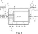
- Fig. 1 is a schematic diagram illustrating a configuration of a gas turbine system 1 according to the present embodiment.
- the gas turbine system 1 includes a turbocharger 11, a generator 12, a combustor 13, a burner 14, a hydrogen tank 15, and a flow rate control valve 16.
- the combustor 13, the burner 14, the hydrogen tank 15, and the flow rate control valve 16 are included in a combustion device 10.
- the turbocharger 11 includes a compressor 11a and a turbine 11b.
- the compressor 11a and the turbine 11b rotate in an integrated manner.
- the compressor 11a and the turbine 11b are connected by a shaft.
- the compressor 11a is provided in an intake flow path 21 connected with the combustor 13.
- the air supplied to the combustor 13 flows through the intake flow path 21.
- An intake port (not illustrated) through which the air is taken in from the outside is provided at an upstream end of the intake flow path 21.
- the air taken in from the intake port passes through the compressor 11a and is sent to the combustor 13.
- the compressor 11a compresses the air and discharges the air to the downstream side.
- the turbine 11b is provided in an exhaust flow path 22 connected with the combustor 13. Exhaust gas discharged from the combustor 13 flows through the exhaust flow path 22. An exhaust port (not illustrated) through which the exhaust gas is discharged to the outside is provided at a downstream end of the exhaust flow path 22. The exhaust gas discharged from the combustor 13 passes through the turbine 11b and is sent to the exhaust port. The turbine 11b generates rotational power by being turned by the exhaust gas.
- the generator 12 is connected with the turbocharger 11.
- the generator 12 generates electric power using the rotational power generated by the turbocharger 11.
- the combustor 13 includes a casing 13a, a liner 13b, and a combustion chamber 13c.
- the casing 13a has a substantially cylindrical shape.
- the liner 13b is included inside the casing 13a.
- the liner 13b has a substantially cylindrical shape.
- the liner 13b is disposed coaxially with the casing 13a.
- the combustion chamber 13c is formed inside the liner 13b. That is, the internal space of the liner 13b corresponds to the combustion chamber 13c.
- the combustion chamber 13c is a substantially cylindrical space.
- the exhaust flow path 22 is connected to the combustion chamber 13c.
- hydrogen and the air are supplied to the combustion chamber 13c.
- hydrogen is used as fuel, and combustion is performed.
- the exhaust gas generated by the combustion in the combustion chamber 13c is discharged to the exhaust flow path 22.
- a space S is formed between the inner surface of the casing 13a and the outer surface of the liner 13b.
- the intake flow path 21 is connected to the space S.
- the air is supplied from the compressor 11a to the space S via the intake flow path 21.
- An opening is formed at an end (an end on the left side in Fig. 1 ) of the liner 13b.
- the burner 14 is inserted through the opening at the end of the liner 13b.
- the burner 14 includes a burner plate 14a and a plurality of hydrogen supply pipes 14b.
- the burner plate 14a closes the opening at the end of the liner 13b. That is, the burner plate 14a closes the end of the combustion chamber 13c.
- the burner plate 14a has a disk shape.
- the hydrogen supply pipes 14b are connected to a surface of the burner plate 14a on a side opposite to the combustion chamber 13c side.
- the hydrogen supply pipes 14b penetrate the casing 13a and extend to the outside of the casing 13a. In Fig. 1 , three hydrogen supply pipes 14b are illustrated. However, the number of hydrogen supply pipes 14b is not limited.
- hydrogen injection holes specifically, hydrogen injection holes 31 to be described later
- air injection holes specifically, a first air injection hole 32 and a second air injection hole 33 to be described later
- the hydrogen injection holes formed in the burner plate 14a communicate with the hydrogen supply pipes 14b.
- Hydrogen is sent to the hydrogen supply pipes 14b as described later.
- Hydrogen sent from the hydrogen supply pipes 14b to the burner plate 14a passes through the hydrogen injection holes of the burner plate 14a and is injected into the combustion chamber 13c.
- the air sent to the space S passes through the space S and then reaches a surface of the burner plate 14a on the side opposite to the combustion chamber 13c.
- the air sent to the burner plate 14a passes through the air injection holes of the burner plate 14a and is injected into the combustion chamber 13c.
- Hydrogen is stored in the hydrogen tank 15.
- hydrogen may be liquid or gas.
- the hydrogen tank 15 is connected with the flow rate control valve 16 via a flow path 23.
- the flow rate control valve 16 is connected with each of the hydrogen supply pipes 14b of the burner 14 via flow paths 24. Hydrogen stored in the hydrogen tank 15 is supplied to the hydrogen supply pipes 14b via the flow path 23, the flow rate control valve 16, and the flow paths 24.
- the flow rate control valve 16 controls (namely, adjusts) a flow rate of hydrogen supplied from the hydrogen tank 15 to the hydrogen supply pipes 14b. With the opening degree of the flow rate control valve 16 adjusted, the amount of hydrogen supplied from the hydrogen tank 15 to the hydrogen supply pipes 14b is adjusted.
- the circumferential direction of the combustion chamber 13c is also simply referred to as a circumferential direction.
- the radial direction of the combustion chamber 13c is also simply referred to as a radial direction.
- the axial direction of the combustion chamber 13c is also simply referred to as an axial direction.
- Fig. 2 is a diagram of the burner plate 14a as viewed from the combustion chamber 13c side (specifically, diagram as viewed from a direction of an arrow Al in Fig. 1 ).
- Fig. 3 is a cross-sectional view taken along line A2-A2 in Fig. 2 .
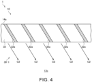
- Fig. 4 is a cross-sectional view taken along line A3-A3 in Fig. 2 .
- Fig. 5 is a cross-sectional view taken along line A4-A4 in Fig. 2 .
- a pair of injection hole groups 30 (specifically, an injection hole group 30-1 and an injection hole group 30-2) is formed in the burner plate 14a.
- Each of the injection hole groups 30 has a plurality of hydrogen injection holes 31, a first air injection hole 32, and a second air injection hole 33.
- Each of the injection hole groups 30 extends in the circumferential direction and has an annular shape.
- the injection hole group 30-1 is disposed on a radially outer side with respect to the injection hole group 30-2. In this manner, the injection hole group 30-1 and the injection hole group 30-2 are included at an interval in the radial direction.
- the number of injection hole groups 30 formed in the burner plate 14a is not limited to this example.
- the number of injection hole groups 30 formed in the burner plate 14a may be one or three or more.
- the hydrogen injection holes 31 face the inside of the combustion chamber 13c.
- the hydrogen injection holes 31 opens on a surface of the burner plate 14a on the combustion chamber 13c side.
- the plurality of hydrogen injection holes 31 is included at intervals in the circumferential direction.
- the hydrogen injection holes 31 are included at equal intervals. However, in each of the injection hole groups 30, the hydrogen injection holes 31 may be included at unequal intervals.
- a manifold 40 communicating with a plurality of hydrogen injection holes 31 is formed for each of the injection hole groups 30.
- the manifolds 40 extend in the circumferential direction.
- the manifolds 40 are formed, for example, in an annular shape.
- a manifold 40 is provided side by side in the axial direction of the combustion chamber 13c with the plurality of hydrogen injection holes 31 of each of the injection hole groups 30.
- a manifold 40 is disposed on the side opposite to the combustion chamber 13c side with respect to the plurality of hydrogen injection holes 31 of each of the injection hole groups 30.
- the cross-sectional shape of the manifold 40 (specifically, the shape in the cross section orthogonal to the extending direction of the manifold 40) is circular.
- the cross-sectional shape of the manifold 40 may be other than circular (such as a polygonal shape).
- the hydrogen supply pipes 14b of the burner 14 are connected to the manifolds 40. Hydrogen is supplied from the hydrogen supply pipes 14b to each of the manifolds 40. The hydrogen supplied to the manifolds 40 is injected from each of the hydrogen injection holes 31 to the combustion chamber 13c as indicated by an arrow C1 in Fig. 3 . Hydrogen supplied to the manifold 40 provided for the injection hole group 30-1 is injected from the plurality of hydrogen injection holes 31 of the injection hole group 30-1 to the combustion chamber 13c. Hydrogen supplied to the manifold 40 provided for the injection hole group 30-2 is injected from the plurality of hydrogen injection holes 31 of the injection hole group 30-2 to the combustion chamber 13c.
- the first air injection holes 32 face the inside of the combustion chamber 13c.
- the first air injection holes 32 penetrate the burner plate 14a from the combustion chamber 13c side to the opposite side to the combustion chamber 13c side.
- the first air injection hole 32 is included on a radially outer side with respect to the plurality of hydrogen injection holes 31.
- the first air injection hole 32 extends in the circumferential direction and is formed in an annular shape. A part of the air sent to the burner plate 14a through the space S in the combustor 13 is injected from the first air injection hole 32 into the combustion chamber 13c as indicated by an arrow C2 in Figs. 3 and 4 .
- the first air injection hole 32 is provided with first swirling blades 32a inclined in the circumferential direction with respect to the combustion-chamber-side axial direction.
- the combustion-chamber-side axial direction is a direction facing the combustion chamber 13c in the axial direction of the combustion chamber 13c.
- To be inclined in the circumferential direction with respect to the combustion-chamber-side axial direction means to extend in a direction of a vector obtained by combining a vector in the circumferential direction with a vector in the combustion-chamber-side axial direction or to be inclined so as to advance in the circumferential direction as it is closer to the combustion chamber 13c.
- the first swirling blades 32a have, for example, a substantially flat plate shape.
- a first swirling blade 32a divides the first air injection hole 32 in the circumferential direction.
- a first swirling blade 32a extends on a plane intersecting the circumferential direction.
- a plurality of first swirling blades 32a is provided at intervals in the circumferential direction.
- the plurality of first swirling blades 32a is provided at equal intervals.
- the plurality of first swirling blades 32a may be provided at unequal intervals.
- the first swirling blades 32a are inclined to a first side (clockwise direction in Fig. 2 ) in the circumferential direction with respect to the combustion-chamber-side axial direction.
- An injection direction of the air injected from the first air injection hole 32 is a direction along the first swirling blades 32a. Therefore, as indicated by the arrow C2 in Fig. 4 , the injection direction of the air injected from the first air injection hole 32 of the injection hole group 30-1 is a direction inclined to the first side in the circumferential direction with respect to the combustion-chamber-side axial direction. Therefore, as indicated by an arrow B1 in Fig. 2 , the air injected from the first air injection hole 32 of the injection hole group 30-1 swirls to the first side in the circumferential direction in the combustion chamber 13c.
- the second air injection holes 33 face the inside of the combustion chamber 13c.
- the second air injection holes 33 penetrate the burner plate 14a from the combustion chamber 13c side to the opposite side to the combustion chamber 13c side.
- the second air injection hole 33 is included on a radially inner side with respect to the plurality of hydrogen injection holes 31.
- the second air injection hole 33 extends in the circumferential direction and is formed in an annular shape. A part of the air sent to the burner plate 14a through the space S in the combustor 13 is injected from the second air injection hole 33 into the combustion chamber 13c as indicated by an arrow C3 in Figs. 3 and 5 .
- the second air injection hole 33 is provided with second swirling blades 33a inclined to the same side as the first swirling blades 32a (specifically, the first swirling blades 32a belonging to the same injection hole group 30) in the circumferential direction with respect to the combustion-chamber-side axial direction.
- the second swirling blades 33a have, for example, a substantially flat plate shape.
- a second swirling blade 33a divides the second air injection hole 33 in the circumferential direction.
- a second swirling blade 33a extends on a plane intersecting the circumferential direction.
- a plurality of second swirling blades 33a is provided at intervals in the circumferential direction.
- the plurality of second swirling blades 33a is provided at equal intervals.
- the plurality of second swirling blades 33a may be provided at unequal intervals.
- the second swirling blades 33a are inclined to the first side (clockwise direction in Fig. 2 ) in the circumferential direction with respect to the combustion-chamber-side axial direction.
- An injection direction of the air injected from the second air injection hole 33 is a direction along the second swirling blades 33a. Therefore, as indicated by the arrow C3 in Fig. 5 , the injection direction of the air injected from the second air injection hole 33 of the injection hole group 30-1 is a direction inclined to the first side in the circumferential direction with respect to the combustion-chamber-side axial direction. Therefore, as indicated by an arrow B2 in Fig. 2 , the air injected from the second air injection hole 33 of the injection hole group 30-1 swirls to the first side in the circumferential direction in the combustion chamber 13c.
- the direction in which the first swirling blades 32a and the second swirling blades 33a are inclined with respect to the combustion-chamber-side axial direction in the injection hole group 30-1 and the direction in which the first swirling blades 32a and the second swirling blades 33a are inclined with respect to the combustion-chamber-side axial direction in the injection hole group 30-2 are on different sides in the circumferential direction. That is, in the first air injection hole 32 of the injection hole group 30-2, the first swirling blades 32a are inclined to a second side in the circumferential direction (counterclockwise direction in Fig. 2 ) with respect to the combustion-chamber-side axial direction. Therefore, as indicated by an arrow B3 in Fig.
- the air injected from the first air injection hole 32 of the injection hole group 30-2 swirls to the second side in the circumferential direction in the combustion chamber 13c.
- the second swirling blades 33a are inclined to the second side in the circumferential direction with respect to the combustion-chamber-side axial direction. Therefore, as indicated by an arrow B4 in Fig. 2 , the air injected from the second air injection hole 33 of the injection hole group 30-2 swirls to the second side in the circumferential direction in the combustion chamber 13c.
- the first air injection hole 32 provided on a radially outer side with respect to the plurality of hydrogen injection holes 31 is provided with the first swirling blades 32a inclined in the circumferential direction with respect to the combustion-chamber-side axial direction.
- the second air injection hole 33 provided on a radially inner side with respect to the plurality of hydrogen injection holes 31 is provided with the second swirling blades 33a inclined to the same side as the first swirling blades 32a in the circumferential direction with respect to the combustion-chamber-side axial direction.
- the hydrogen injected from the hydrogen injection holes 31 is rapidly mixed with the air by the swirl flow of air generated by the air injected from the first air injection hole 32 and the second air injection hole 33. Therefore, the ignition position is on the inner side of the combustion chamber 13c as compared with a case where hydrogen and the air are supplied to the combustion chamber 13c in a state of having been mixed in advance. Therefore, backfire is suppressed. In addition, erosion of the burner 14 is suppressed. Therefore, the burner 14 can be protected from flame. In addition, by adjusting the supply amount of the air as appropriate and lowering the temperature of flame, the emission amount of NOx is also reduced.
- the inclination angles (namely, the inclination angle with respect to the combustion-chamber-side axial direction) of the first swirling blades 32a and the second swirling blades 33a may match or be different.
- Fig. 6 is a schematic diagram illustrating the flow of gas generated in the combustion chamber 13c.
- a swirl flow of air generated by the air injected from the first air injection hole 32 and the second air injection hole 33 is indicated by an arrow D1.
- a circulating flow is generated which is a flow of gas passing through the vicinity of the central axis of the swirl flow (namely, through the vicinity of the central axis of the combustion chamber 13c) toward the burner plate 14a side.
- the direction in which the first swirling blades 32a and the second swirling blades 33a are inclined with respect to the combustion-chamber-side axial direction in the injection hole group 30-1 and the direction in which the first swirling blades 32a and the second swirling blades 33a are inclined with respect to the combustion-chamber-side axial direction in the injection hole group 30-2 are on different sides in the circumferential direction.
- the swirling direction specifically, the clockwise direction in Fig. 2
- the swirling direction specifically, the counterclockwise direction in Fig.
- first swirling blades 32a and the second swirling blades 33a of the injection hole group 30-1 are inclined to the first side (clockwise direction in Fig. 2 ) in the circumferential direction with respect to the combustion-chamber-side axial direction.
- first swirling blades 32a and the second swirling blades 33a of the injection hole group 30-1 may be inclined to the second side in the circumferential direction (counterclockwise direction in Fig. 2 ) with respect to the combustion-chamber-side axial direction.
- first swirling blades 32a and the second swirling blades 33a of the injection hole group 30-2 are inclined to the first side in the circumferential direction with respect to the combustion-chamber-side axial direction.
- the injection hole groups 30 are formed in the burner plate 14a that closes the end of the combustion chamber 13c. Therefore, the injection hole groups 30 can be easily formed by integrally molding the burner plate 14a by metal lamination technology or the like.
- integrally molding the burner plate 14a in this manner the structure of the burner 14 is simplified, the burner 14 is downsized, and the manufacturing cost of the burner 14 is reduced as compared with the case where the members forming the injection hole groups 30 are separate from the burner plate 14a.
- leakage of hydrogen from joint portions of members is suppressed.
- the occurrence of a crack at joint portions due to thermal stress is suppressed.
- the manifolds 40 communicating with the plurality of hydrogen injection holes 31 are formed in the burner plate 14a. Therefore, the manifolds 40 can be easily formed by integrally molding the burner plate 14a by metal lamination technology or the like.
- integrally molding the burner plate 14a in this manner the structure of the burner 14 is simplified, the burner 14 is downsized, and the manufacturing cost of the burner 14 is reduced as compared with the case where the members forming the manifolds 40 are separate from the burner plate 14a.
- leakage of hydrogen from joint portions of members is suppressed.
- the occurrence of a crack at joint portions due to thermal stress is suppressed.
- each of divided portions (for example, each of portions obtained by dividing at predetermined angles in the circumferential direction) of the burner plate 14a may be integrally molded by metal lamination technology or the like, and the obtained members may be assembled. Also in this case, the manufacturing cost of the burner 14 is reduced, leakage of hydrogen from joint portions of the member is suppressed, and occurrence of a crack in the joint portions due to thermal stress is suppressed.
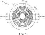
- Fig. 7 is a diagram of a burner plate 14aA according to a first modification as viewed from the combustion chamber 13c side. As illustrated in Fig. 7 , a combustion device 10A of a gas turbine system 1A according to the first modification includes the burner plate 14aA.
- the direction in which first swirling blades 32a and second swirling blades 33a are inclined with respect to the combustion-chamber-side axial direction in an injection hole group 30-1 and the direction in which the first swirling blades 32a and the second swirling blades 33a are inclined with respect to the combustion-chamber-side axial direction in the injection hole group 30-2 are on the same side in the circumferential direction.
- the first swirling blades 32a and the second swirling blades 33a of the injection hole group 30-1 are inclined to a first side (clockwise direction in Fig. 7 ) in the circumferential direction with respect to the combustion-chamber-side axial direction. Therefore, as indicated by arrows B1 and B2 in Fig. 7 , the air injected from a first air injection hole 32 and a second air injection hole 33 of the injection hole group 30-1 swirls to the first side in the circumferential direction in the combustion chamber 13c.
- the first swirling blades 32a and the second swirling blades 33a of the injection hole group 30-2 are inclined to the first side (clockwise direction in Fig. 7 ) in the circumferential direction with respect to the combustion-chamber-side axial direction. Therefore, as indicated by arrows B3 and B4 in Fig. 7 , the air injected from a first air injection hole 32 and a second air injection hole 33 of the injection hole group 30-2 swirls to the first side in the circumferential direction in the combustion chamber 13c.
- the direction in which the first swirling blades 32a and the second swirling blades 33a are inclined with respect to the combustion-chamber-side axial direction in the injection hole group 30-1 and the direction in which the first swirling blades 32a and the second swirling blades 33a are inclined with respect to the combustion-chamber-side axial direction in the injection hole group 30-2 are on the same side in the circumferential direction.
- the swirling direction specifically, the clockwise direction in Fig. 7 , of a swirl flow of air generated by the air injected from the injection hole group 30-1 and the swirling direction (specifically, the clockwise direction in Fig.
- the inclination angles (namely, the inclination angles with respect to the combustion-chamber-side axial direction) of the first swirling blades 32a and the second swirling blades 33a of the injection hole group 30-2 may be smaller than the inclination angles of the first swirling blades 32a and the second swirling blades 33a of the injection hole group 30-1.
- a velocity component in the swirling direction of the swirl flow of air generated by the air injected from the injection hole group 30-2 can be easily made smaller than a velocity component in the swirling direction of the swirl flow of air generated by the air injected from the injection hole group 30-1. Therefore, a circulating flow directed toward the burner plate 14aA side through the vicinity of the central axis of the swirl flow is suppressed from being excessively strong, thereby preventing flame from approaching the burner plate 14aA.
- first swirling blades 32a and the second swirling blades 33a of the injection hole group 30-1 are inclined to the first side (clockwise direction in Fig. 7 ) in the circumferential direction with respect to the combustion-chamber-side axial direction.
- first swirling blades 32a and the second swirling blades 33a of the injection hole group 30-1 may be inclined to a second side in the circumferential direction (counterclockwise direction in Fig. 7 ) with respect to the combustion-chamber-side axial direction.
- the first swirling blades 32a and the second swirling blades 33a of the injection hole group 30-2 are inclined to the second side in the circumferential direction with respect to the combustion-chamber-side axial direction.
- Fig. 8 is a diagram of a burner plate 14aB according to a second modification as viewed from the combustion chamber 13c side.
- a combustion device 10B of a gas turbine system 1B according to a second modification includes a burner plate 14aB.
- the burner plate 14aB is different from the burner plate 14a in that a third air injection hole 51 is included.
- the third air injection hole 51 faces the inside of the combustion chamber 13c.
- the third air injection hole 51 penetrates the burner plate 14aB from the combustion chamber 13c side to the side opposite to the combustion chamber 13c side.
- the third air injection hole 51 is provided on a radially inner side with respect to the injection hole group 30-2.
- the third air injection hole 51 is included on a radially inner side with respect to an injection hole group 30 on the radially innermost side. That is, the third air injection hole 51 is included on a radially inner side with respect to any injection hole group 30.
- the third air injection hole 51 is disposed coaxially with the central axis of the combustion chamber 13c. However, the central axis of the third air injection hole 51 and the central axis of the combustion chamber 13c may not coincide with each other.
- the third air injection hole 51 has a columnar shape. However, the third air injection hole 51 may have a shape other than the columnar shape (for example, a polygonal prism shape or the like).
- a part of the air sent to the burner plate 14aB through the space S in the combustor 13 is injected from the third air injection hole 51 into the combustion chamber 13c.
- the injection direction of the air injected from the third air injection hole 51 is the axial direction of the combustion chamber 13c.
- the injection direction of the air injected from the third air injection hole 51 may be inclined with respect to the axial direction of the combustion chamber 13c.
- the third air injection hole 51 is included on a radially inner side with respect to the injection hole group 30-2.
- a circulating flow flowing toward the burner plate 14aB side through the vicinity of the central axis of the swirl flow can be weakened by the air injected from the third air injection hole 51. This prevents flame from approaching the burner plate 14aB more effectively. Therefore, erosion of the burner 14 is more effectively suppressed.
- the swirling direction of the swirl flow of air generated by the air injected from the injection hole group 30-1 is opposite to the swirling direction of the swirl flow of air generated by the air injected from the injection hole group 30-2.
- the swirling direction of the swirl flow of air generated by the air injected from the injection hole group 30-1 and the swirling direction of the swirl flow of air generated by the air injected from the injection hole group 30-2 may be the same direction.
- Fig. 9 is a diagram of a burner plate 14aC according to a third modification as viewed from the combustion chamber 13c side.
- a combustion device 10C of a gas turbine system 1C according to a third modification includes a burner plate 14aC.
- the burner plate 14aC is different from the burner plate 14a in that a plurality of third air injection holes 52, a plurality of fourth air injection holes 53, and a plurality of fifth air injection holes 54 are included.
- the third air injection holes 52, the fourth air injection holes 53, and the fifth air injection holes 54 face the inside of the combustion chamber 13c.
- the third air injection holes 52, the fourth air injection holes 53, and the fifth air injection holes 54 penetrate the burner plate 14aC from the combustion chamber 13c side to the opposite side to the combustion chamber 13c side.
- the flow path cross-sectional shapes of the third air injection holes 52, the fourth air injection holes 53, and the fifth air injection holes 54 are circular.
- the flow path cross-sectional shapes of the third air injection holes 52, the fourth air injection holes 53, and the fifth air injection holes 54 may have a shape other than the circular shape (for example, a polygonal shape or the like).
- the flow path diameters of the third air injection holes 52, the fourth air injection holes 53, and the fifth air injection holes 54 are smaller than the flow path diameter of the third air injection hole 51 of the burner plate 14aB described above.
- the flow path diameters of the third air injection holes 52, the fourth air injection holes 53, and the fifth air injection holes 54 coincide with each other.
- the flow path diameters of the third air injection holes 52, the fourth air injection holes 53, and the fifth air injection holes 54 may be different from each other.
- a part of the air sent to the burner plate 14aC through the space S in the combustor 13 is injected into the combustion chamber 13c from the third air injection holes 52, the fourth air injection holes 53, and the fifth air injection holes 54.
- the injection direction of the air injected from the third air injection holes 52, the fourth air injection holes 53, and the fifth air injection holes 54 is the axial direction of the combustion chamber 13c.
- the injection direction of the air injected from the third air injection holes 52, the fourth air injection holes 53, and the fifth air injection holes 54 may be inclined with respect to the axial direction of the combustion chamber 13c.
- the third air injection holes 52 are included on a radially inner side with respect to the injection hole group 30-2.
- the fourth air injection holes 53 are included on a radially inner side with respect to an injection hole group 30-1 and on a radially outer side with respect to an injection hole group 30-2.
- the fifth air injection holes 54 are included on a radially outer side with respect to the injection hole group 30-1.
- the third air injection hole 52 is included on a radially inner side with respect to the injection hole group 30-2.
- a circulating flow flowing toward the burner plate 14aC side through the vicinity of the central axis of the swirl flow can be weakened by the air injected from the third air injection hole 52. This prevents flame from approaching the burner plate 14aC more effectively. Therefore, erosion of the burner 14 is more effectively suppressed.
- the third air injection holes 52, the fourth air injection holes 53, and the fifth air injection holes 54 are included over a wide area in the burner plate 14aC.
- the burner plate 14aC is cooled by the air passing through the third air injection holes 52, the fourth air injection holes 53, and the fifth air injection holes 54.
- the swirling direction of a swirl flow of air generated by the air injected from the injection hole group 30-1 is opposite to the swirling direction of a swirl flow of air generated by the air injected from the injection hole group 30-2.
- the swirling direction of the swirl flow of air generated by the air injected from the injection hole group 30-1 and the swirling direction of the swirl flow of air generated by the air injected from the injection hole group 30-2 may be the same direction.
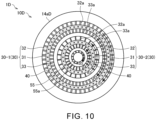
- Fig. 10 is a diagram of a burner plate 14aD according to a fourth modification as viewed from the combustion chamber 13c side. As illustrated in Fig. 10 , a combustion device 10D of a gas turbine system 1D according to the fourth modification includes the burner plate 14aD.
- the burner plate 14aD is different from the burner plate 14a in that a third air injection hole 55 is included.
- the third air injection hole 55 faces the inside of the combustion chamber 13c.
- the third air injection hole 55 penetrates the burner plate 14aD from the combustion chamber 13c side to the side opposite to the combustion chamber 13c side.
- the third air injection hole 55 is provided on a radially inner side with respect to an injection hole group 30-2.
- the third air injection hole 55 extends in the circumferential direction and is formed in an annular shape. A part of the air sent to the burner plate 14aD through the space S in the combustor 13 is injected from the third air injection hole 55 into the combustion chamber 13c.
- the third air injection hole 55 is provided with third swirling blades 55a inclined in the circumferential direction with respect to the combustion-chamber-side axial direction.
- the third swirling blades 55a have, for example, a substantially flat plate shape.
- a third swirling blade 55a divides the third air injection hole 55 in the circumferential direction.
- a third swirling blade 55a extends on a plane intersecting the circumferential direction.
- a plurality of third swirling blades 55a is provided at intervals in the circumferential direction.
- the plurality of third swirling blades 55a is provided at equal intervals.
- the plurality of third swirling blades 55a may be provided at unequal intervals.
- the direction in which the third swirling blades 55a are inclined with respect to the combustion-chamber-side axial direction in the third air injection hole 55 and the direction in which first swirling blades 32a and second swirling blades 33a are inclined with respect to the combustion-chamber-side axial direction in an injection hole group 30-2 adjacent to the third air injection hole 55 are on different sides in the circumferential direction.
- the first swirling blades 32a and the second swirling blades 33a of the injection hole group 30-2 are inclined to the second side (counterclockwise direction in Fig. 10 ) in the circumferential direction with respect to the combustion-chamber-side axial direction. That is, the third swirling blade 55a is inclined to the first side (clockwise direction in Fig.
- the third air injection hole 55 is included on a radially inner side with respect to the injection hole group 30-2.
- a circulating flow flowing toward the burner plate 14aD side through the vicinity of the central axis of the swirl flow can be weakened by the air injected from the third air injection hole 51. This prevents flame from approaching the burner plate 14aD more effectively. Therefore, erosion of the burner 14 is more effectively suppressed.
- the direction in which the third swirling blades 55a are inclined with respect to the combustion-chamber-side axial direction in the third air injection hole 55 and the direction in which the first swirling blades 32a and the second swirling blades 33a are inclined with respect to the combustion-chamber-side axial direction in the injection hole group 30-2 adjacent to the third air injection hole 55 are on different sides in the circumferential direction.
- the swirling direction (specifically, the clockwise direction in Fig. 10 ) of a swirl flow of air generated by the air injected from the third air injection hole 55 and the swirling direction (specifically, the counterclockwise direction in Fig.
- the swirl flow of air generated by the air injected from the third air injection hole 55 and the swirl flow of air generated by the air injected from the injection hole group 30-2 weaken each other. Therefore, the circulating flow passing through the vicinity of the central axis of the swirl flow toward the burner plate 14aD is weakened. This prevents flame from approaching the burner plate 14aD further effectively. Therefore, erosion of the burner 14 is further effectively suppressed.
- the third swirling blades 55a may not be provided in the third air injection hole 55.
- the swirling direction of a swirl flow of air generated by the air injected from the injection hole group 30-1 is opposite to the swirling direction of the swirl flow of air generated by the air injected from the injection hole group 30-2.
- the swirling direction of the swirl flow of air generated by the air injected from the injection hole group 30-1 and the swirling direction of the swirl flow of air generated by the air injected from the injection hole group 30-2 may be the same direction.
- Fig. 11 is a cross-sectional view illustrating a burner plate 14aE according to a fifth modification. As illustrated in Fig. 11 , a combustion device 10E of a gas turbine system 1E according to the fifth modification includes the burner plate 14aE.
- the burner plate 14aE is different from the burner plate 14a in the configurations of a wall portion 61 on the outer peripheral side of a first air injection hole 32 and a wall portion 62 on the inner peripheral side of a second air injection hole 33. Note that the configurations of the wall portion 61 and the wall portion 62 are similar in each of injection hole groups 30.
- the wall portion 61 on the outer peripheral side of the first air injection hole 32 extends closer to the combustion chamber 13c than the first air injection hole 32 is.
- a tapered portion 61a is formed on the combustion chamber 13c side of the wall portion 61.
- the tapered portion 61a is inclined on a radially inner side with respect to the combustion-chamber-side axial direction.
- the wall portion 62 on the inner peripheral side of the second air injection hole 33 extends closer to the combustion chamber 13c than the second air injection hole 33 is.
- a tapered portion 62a is formed on the combustion chamber 13c side of the wall portion 62.
- the tapered portion 62a is inclined on a radially outer side with respect to the combustion-chamber-side axial direction.
- Hydrogen injected from the hydrogen injection holes 31, air injected from the first air injection hole 32, and air injected from the second air injection hole 33 are narrowed between the tapered portion 61a of the wall portion 61 and the tapered portion 62a of the wall portion 62.
- the flow rate of hydrogen and air increases between the tapered portion 61a of the wall portion 61 and the tapered portion 62a of the wall portion 62, thereby promoting mixing of hydrogen and air.
- the tapered portion 61a of the wall portion 61 and the tapered portion 62a of the wall portion 62 may be included only in some injection hole groups 30 or may be included in all the injection hole groups 30.
- the combustion device 10E is an example in which the tapered portion 61a of the wall portion 61 and the tapered portion 62a of the wall portion 62 are added to the above-described combustion device 10.
- the tapered portion 61a of the wall portion 61 and the tapered portion 62a of the wall portion 62 may be added to the combustion device 10A, the combustion device 10B, the combustion device 10C, or the combustion device 10D described above.
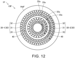
- Fig. 12 is a diagram illustrating a first example in which directions inclined with respect to the combustion-chamber-side axial direction of first swirling blades 32a and second swirling blades 33a in each of injection hole groups are on different sides in the circumferential direction.
- Fig. 12 illustrates the burner plate 14aF of a combustion device 10F of a gas turbine system 1F according to the first example as viewed from the combustion chamber 13c side.
- first swirling blades 32a of an injection hole group 30-1 are inclined to the first side in the circumferential direction (clockwise direction in Fig. 12 ) with respect to the combustion-chamber-side axial direction. Therefore, as indicated by an arrow B1 in Fig. 12 , the air injected from a first air injection hole 32 of the injection hole group 30-1 swirls to the first side in the circumferential direction in the combustion chamber 13c.
- second swirling blades 33a of the injection hole group 30-1 are inclined to the second side in the circumferential direction (counterclockwise direction in Fig. 12 ) with respect to the combustion-chamber-side axial direction. Therefore, as indicated by an arrow B2 in Fig. 12 , the air injected from the second air injection hole 33 of the injection hole group 30-1 swirls to the second side in the circumferential direction in the combustion chamber 13c.
- first swirling blades 32a of an injection hole group 30-2 are inclined to the first side in the circumferential direction (clockwise direction in Fig. 12 ) with respect to the combustion-chamber-side axial direction. Therefore, as indicated by an arrow B3 in Fig. 12 , the air injected from the first air injection hole 32 of the injection hole group 30-2 swirls to the first side in the circumferential direction in the combustion chamber 13c.
- the second swirling blades 33a of the injection hole group 30-2 are inclined to the second side in the circumferential direction (counterclockwise direction in Fig. 12 ) with respect to the combustion-chamber-side axial direction. Therefore, as indicated by an arrow B4 in Fig. 12 , the air injected from the second air injection hole 33 of the injection hole group 30-2 swirls to the second side in the circumferential direction in the combustion chamber 13c.
- the ignition position is on the inner side of the combustion chamber 13c, and thus backfire is suppressed. Therefore, the burner 14 can be protected from flame.
- directions inclined with respect to the combustion-chamber-side axial direction of the second swirling blades 33a of the injection hole group 30-1 and the first swirling blades 32a of the injection hole group 30-2 are on different sides in the circumferential direction.
- the swirling direction (specifically, the counterclockwise direction in Fig. 12 ) of a swirl flow of air generated by the air injected from the second swirling blades 33a of the injection hole group 30-1 and the swirling direction (specifically, the clockwise direction in Fig. 12 ) of a swirl flow of air generated by the air injected from the first swirling blades 32a of the injection hole group 30-2 are opposite directions.
- the swirl flow of air generated by the air injected from the second swirling blades 33a of the injection hole group 30-1 and the swirl flow of air generated by the air injected from the first swirling blades 32a of the injection hole group 30-2 weaken each other. Therefore, a circulating flow (namely, a flow indicated by an arrow D2 in Fig. 6 ) passing through the vicinity of the central axis of the swirl flow toward the burner plate 14aF side is weakened. This prevents flame from approaching the burner plate 14aF. Therefore, erosion of the burner 14 is suppressed.
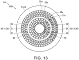
- Fig. 13 is a diagram illustrating a second example in which directions inclined with respect to the combustion-chamber-side axial direction of the first swirling blades 32a and the second swirling blades 33a in each of the injection hole groups are different sides in the circumferential direction.
- Fig. 13 illustrates a burner plate 14aG of a combustion device 10G of a gas turbine system 1G according to the second example as viewed from the combustion chamber 13c side.
- first swirling blades 32a of an injection hole group 30-1 are inclined to the first side in the circumferential direction (clockwise direction in Fig. 13 ) with respect to the combustion-chamber-side axial direction. Therefore, as indicated by an arrow B1 in Fig. 13 , the air injected from a first air injection hole 32 of the injection hole group 30-1 swirls to the first side in the circumferential direction in the combustion chamber 13c.
- the second swirling blades 33a of the injection hole group 30-1 are inclined to the second side in the circumferential direction (counterclockwise direction in Fig. 13 ) with respect to the combustion-chamber-side axial direction. Therefore, as indicated by an arrow B2 in Fig. 13 , the air injected from a second air injection hole 33 of the injection hole group 30-1 swirls to the second side in the circumferential direction in the combustion chamber 13c.
- first swirling blades 32a of the injection hole group 30-2 are inclined to the second side in the circumferential direction (counterclockwise direction in Fig. 13 ) with respect to the combustion-chamber-side axial direction. Therefore, as indicated by an arrow B3 in Fig. 13 , the air injected from a first air injection hole 32 of the injection hole group 30-2 swirls to the second side in the circumferential direction in the combustion chamber 13c.
- second swirling blades 33a of the injection hole group 30-2 are inclined to the first side (clockwise direction in Fig. 13 ) in the circumferential direction with respect to the combustion-chamber-side axial direction. Therefore, as indicated by an arrow B4 in Fig. 13 , the air injected from the second air injection hole 33 of the injection hole group 30-2 swirls to the first side in the circumferential direction in the combustion chamber 13c.
- the directions inclined with respect to the combustion-chamber-side axial direction of the second swirling blades 33a of the injection hole group 30-1 and the first swirling blades 32a of the injection hole group 30-2 are on the same side in the circumferential direction.
- the swirling direction (specifically, the counterclockwise direction in Fig. 13 ) of a swirl flow of air generated by the air injected from the second swirling blades 33a of the injection hole group 30-1 and the swirling direction (specifically, the counterclockwise direction in Fig. 13 ) of a swirl flow of air generated by the air injected from the first swirling blades 32a of the injection hole group 30-2 are the same direction.
- the third air injection hole 51 illustrated in the example of Fig. 8 , the third air injection holes 52, the fourth air injection holes 53, and the fifth air injection holes 54 illustrated in the example of Fig. 9 , the third air injection hole 55 illustrated in the example of Fig. 10 , the tapered portion 61a of the wall portion 61 and the tapered portion 62a of the wall portion 62 illustrated in the example of Fig. 11 may be each added to the combustion device 10F of Fig. 12 and the combustion device 10G of Fig. 13 .
- the gas turbine system 1A, the gas turbine system 1B, the gas turbine system 1C, the gas turbine system 1D, the gas turbine system 1E, the gas turbine system 1F, and the gas turbine system 1G the examples in which the rotational power generated by the turbocharger 11 is used as the energy for driving the generator 12 has been described above.
- the rotational power generated by the turbocharger 11 may be used for other applications (for example, for the purpose of driving a mobile body such as a ship).
- the shapes of the combustion chamber 13c are substantially cylindrical.
- the shape of the combustion chamber 13c is not limited to this example.
- the combustion chamber 13c may be a substantially cylindrical space.
- the shapes of the burner plate 14a, the burner plate 14aA, the burner plate 14aB, the burner plate 14aC, the burner plate 14aD, the burner plate 14aE, the burner plate 14aF, and the burner plate 14aG can be modified as appropriate depending on the shape of the combustion chamber 13c.
- the air sent from the compressor 11a to the combustor 13 passes between the outer curved surface of the liner 13b and the inner curved surface of the casing 13a and then is sent to the combustion chamber 13c.
- the path of the air sent from the compressor 11a to the combustor 13 is not limited to this example (namely, the reverse-flow type).
- Gas turbine system 1A Gas turbine system 1B: Gas turbine system 1C: Gas turbine system 1D: Gas turbine system 1E: Gas turbine system 1F: Gas turbine system 1G: Gas turbine system 10: Combustion device 10A: Combustion device 10B: Combustion device 10C: Combustion device 10D: Combustion device 10E: Combustion device 10F: Combustion device 10G: Combustion device 13c: Combustion chamber 14a: Burner plate 14aA: Burner plate 14aB: Burner plate 14aC: Burner plate 14aD: Burner plate 14aE: Burner plate 14aF: Burner plate 14aG: Burner plate 30: Injection hole group 30-1: Injection hole group 30-2: Injection hole group 31: Hydrogen injection hole 32: First air injection hole 32a: First swirling blade 33: Second air injection hole 33a: Second swirling blade 40: Manifold 51: Third air injection hole 52: Third air injection hole 55: Third air injection hole 55a: Third swirling blade
Landscapes
- Engineering & Computer Science (AREA)
- Chemical & Material Sciences (AREA)
- Combustion & Propulsion (AREA)
- Mechanical Engineering (AREA)
- General Engineering & Computer Science (AREA)
- Pre-Mixing And Non-Premixing Gas Burner (AREA)
Abstract
Description
- The present disclosure relates to a combustion device and a gas turbine system. The present application claims the benefit of priority based on
Japanese Patent Application No. 2021-051545 filed on March 25, 2021 - Gas turbine systems, with which power is obtained by combusting fuel in a combustor, are used. Some of the gas turbine systems use, for example, hydrogen as fuel as disclosed in
Patent Literature 1. By using hydrogen as fuel, carbon dioxide emission is suppressed. - Patent Literature 1:
JP 2015-014400 A - The rate of combustion of hydrogen is quite high compared to the rate of combustion of other fuels such as natural gas. Therefore, similarly to the case where natural gas or the like is used as fuel, when the fuel and the air are mixed in advance and supplied from a burner to a combustion chamber of a combustor, in the case where hydrogen is used as the fuel, backfire (namely, a phenomenon in which the flame flows back into the burner) is likely to occur. In addition, the temperature of the flame formed by combustion of hydrogen is higher than the temperature of flames formed by combustion of other fuels. Therefore, the burner is easily eroded by the flame. Thus, there is a high need to protect the burner from the flame.
- An object of the present disclosure is to provide a combustion device and a gas turbine system capable of protecting a burner from flame.
- In order to solve the above problem, a combustion device according to the present disclosure includes: a combustion chamber; a plurality of hydrogen injection holes facing inside of the combustion chamber, the plurality of hydrogen injection holes included at intervals in a circumferential direction of the combustion chamber; a first air injection hole facing the inside of the combustion chamber and extending in the circumferential direction on a radially outer side with respect to the plurality of hydrogen injection holes, the first air injection hole being annular; a second air injection hole facing the inside of the combustion chamber and extending in the circumferential direction on a radially inner side with respect to the plurality of hydrogen injection holes, the second air injection hole being annular; a first swirling blade provided in the first air injection hole and inclined in the circumferential direction with respect to a combustion-chamber-side axial direction, the combustion-chamber-side axial direction being a part of an axial direction of the combustion chamber, the part facing the combustion chamber; and a second swirling blade provided in the second air injection hole and inclined to a same side as the first swirling blade in the circumferential direction with respect to the combustion-chamber-side axial direction.
- A pair of injection hole groups each having the plurality of hydrogen injection holes, the first air injection hole, and the second air injection hole may be included at an interval in a radial direction of the combustion chamber, and a direction in which the first swirling blade and the second swirling blade are inclined with respect to the combustion-chamber-side axial direction in one of the injection hole groups and a direction in which the first swirling blade and the second swirling blade are inclined with respect to the combustion-chamber-side axial direction in the other injection hole group may be on different sides in the circumferential direction.
- A pair of injection hole groups each having the plurality of hydrogen injection holes, the first air injection hole, and the second air injection hole may be included at an interval in a radial direction of the combustion chamber, and a direction in which the first swirling blade and the second swirling blade are inclined with respect to the combustion-chamber-side axial direction in one of the injection hole groups and a direction in which the first swirling blade and the second swirling blade are inclined with respect to the combustion-chamber-side axial direction in the other injection hole group may be on a same side in the circumferential direction.
- A third air injection hole may be further included, the third air injection hole provided on a radially inner side with respect to an injection hole group including the plurality of hydrogen injection holes, the first air injection hole, and the second air injection hole, the third air injection hole facing the inside of the combustion chamber.
- The third air injection hole may extend in the circumferential direction and be formed in an annular shape, and the third air injection hole may be provided with a third swirling blade inclined in the circumferential direction with respect to the combustion-chamber-side axial direction.
- The direction in which the third swirling blade is inclined with respect to the combustion-chamber-side axial direction in the third air injection hole and the direction in which the first swirling blade and the second swirling blade are inclined with respect to the combustion-chamber-side axial direction in the injection hole group adjacent to the third air injection hole may be on different sides in the circumferential direction.
- A burner plate closing an end of the combustion chamber may be included, and an injection hole group including a plurality of hydrogen injection holes, a first air injection hole, and a second air injection hole may be formed in the burner plate.
- A manifold communicating with the plurality of hydrogen injection holes may be formed in the burner plate.
- In order to solve the above disadvantage, a gas turbine system of the present disclosure includes the combustion device described above.
- According to the present disclosure, a burner can be protected from flame.
-
-
Fig. 1 is a schematic diagram illustrating a configuration of a gas turbine system according to an embodiment of the present disclosure. -
Fig. 2 is a diagram of a burner plate according to the embodiment of the present disclosure as viewed from a combustion chamber side. -
Fig. 3 is a cross-sectional view taken along line A2-A2 inFig. 2 . -
Fig. 4 is a cross-sectional view taken along line A3-A3 inFig. 2 . -
Fig. 5 is a cross-sectional view taken along line A4-A4 inFig. 2 . -
Fig. 6 is a schematic diagram illustrating the flow of gas generated in the combustion chamber according to the embodiment of the present disclosure. -
Fig. 7 is a diagram of a burner plate according to a first modification as viewed from a combustion chamber side. -
Fig. 8 is a diagram of a burner plate according to a second modification as viewed from a combustion chamber side. -
Fig. 9 is a diagram of a burner plate according to a third modification as viewed from a combustion chamber side. -
Fig. 10 is a diagram of a burner plate according to a fourth modification as viewed from a combustion chamber side. -
Fig. 11 is a cross-sectional view illustrating a burner plate according to a fifth modification. -
Fig. 12 is a diagram illustrating a first example in which directions inclined with respect to the combustion-chamber-side axial direction are on different sides in the circumferential direction between the first swirling blades and the second swirling blades in each of the injection hole groups. -
Fig. 13 is a diagram illustrating a second example in which directions inclined with respect to the combustion-chamber-side axial direction are on different sides in the circumferential direction between the first swirling blades and the second swirling blades in each of the injection hole groups. - Embodiments of the present disclosure will be described below by referring to the accompanying drawings. Dimensions, materials, other specific numerical values, and the like illustrated in the embodiments are merely an example for facilitating understanding, and the present disclosure is not limited thereto unless otherwise specified. Note that, in the present specification and the drawings, components having substantially the same function and structure are denoted by the same symbol, and redundant explanations are omitted. Illustration of components not directly related to the present disclosure is omitted.
-
Fig. 1 is a schematic diagram illustrating a configuration of agas turbine system 1 according to the present embodiment. As illustrated inFig. 1 , thegas turbine system 1 includes aturbocharger 11, agenerator 12, acombustor 13, aburner 14, ahydrogen tank 15, and a flowrate control valve 16. - In the
gas turbine system 1, thecombustor 13, theburner 14, thehydrogen tank 15, and the flowrate control valve 16 are included in acombustion device 10. - The
turbocharger 11 includes acompressor 11a and aturbine 11b. Thecompressor 11a and theturbine 11b rotate in an integrated manner. Thecompressor 11a and theturbine 11b are connected by a shaft. - The
compressor 11a is provided in anintake flow path 21 connected with thecombustor 13. The air supplied to thecombustor 13 flows through theintake flow path 21. An intake port (not illustrated) through which the air is taken in from the outside is provided at an upstream end of theintake flow path 21. The air taken in from the intake port passes through thecompressor 11a and is sent to thecombustor 13. Thecompressor 11a compresses the air and discharges the air to the downstream side. - The
turbine 11b is provided in anexhaust flow path 22 connected with thecombustor 13. Exhaust gas discharged from thecombustor 13 flows through theexhaust flow path 22. An exhaust port (not illustrated) through which the exhaust gas is discharged to the outside is provided at a downstream end of theexhaust flow path 22. The exhaust gas discharged from thecombustor 13 passes through theturbine 11b and is sent to the exhaust port. Theturbine 11b generates rotational power by being turned by the exhaust gas. - The
generator 12 is connected with theturbocharger 11. Thegenerator 12 generates electric power using the rotational power generated by theturbocharger 11. - The
combustor 13 includes acasing 13a, aliner 13b, and acombustion chamber 13c. Thecasing 13a has a substantially cylindrical shape. Theliner 13b is included inside thecasing 13a. Theliner 13b has a substantially cylindrical shape. Theliner 13b is disposed coaxially with thecasing 13a. Thecombustion chamber 13c is formed inside theliner 13b. That is, the internal space of theliner 13b corresponds to thecombustion chamber 13c. Thecombustion chamber 13c is a substantially cylindrical space. Theexhaust flow path 22 is connected to thecombustion chamber 13c. - As described later, hydrogen and the air are supplied to the
combustion chamber 13c. In thecombustion chamber 13c, hydrogen is used as fuel, and combustion is performed. The exhaust gas generated by the combustion in thecombustion chamber 13c is discharged to theexhaust flow path 22. A space S is formed between the inner surface of thecasing 13a and the outer surface of theliner 13b. Theintake flow path 21 is connected to the space S. The air is supplied from thecompressor 11a to the space S via theintake flow path 21. An opening is formed at an end (an end on the left side inFig. 1 ) of theliner 13b. Theburner 14 is inserted through the opening at the end of theliner 13b. - The
burner 14 includes aburner plate 14a and a plurality ofhydrogen supply pipes 14b. Theburner plate 14a closes the opening at the end of theliner 13b. That is, theburner plate 14a closes the end of thecombustion chamber 13c. Theburner plate 14a has a disk shape. Thehydrogen supply pipes 14b are connected to a surface of theburner plate 14a on a side opposite to thecombustion chamber 13c side. Thehydrogen supply pipes 14b penetrate thecasing 13a and extend to the outside of thecasing 13a. InFig. 1 , threehydrogen supply pipes 14b are illustrated. However, the number ofhydrogen supply pipes 14b is not limited. - In the
burner plate 14a, as described later with reference toFigs. 2 to 5 , hydrogen injection holes (specifically, hydrogen injection holes 31 to be described later) and air injection holes (specifically, a firstair injection hole 32 and a secondair injection hole 33 to be described later) are formed. The hydrogen injection holes formed in theburner plate 14a communicate with thehydrogen supply pipes 14b. Hydrogen is sent to thehydrogen supply pipes 14b as described later. Hydrogen sent from thehydrogen supply pipes 14b to theburner plate 14a passes through the hydrogen injection holes of theburner plate 14a and is injected into thecombustion chamber 13c. As indicated by an alternate long and short dash line arrow inFig. 1 , the air sent to the space S passes through the space S and then reaches a surface of theburner plate 14a on the side opposite to thecombustion chamber 13c. The air sent to theburner plate 14a passes through the air injection holes of theburner plate 14a and is injected into thecombustion chamber 13c. - Hydrogen is stored in the
hydrogen tank 15. Note that, in thehydrogen tank 15, hydrogen may be liquid or gas. Thehydrogen tank 15 is connected with the flowrate control valve 16 via aflow path 23. The flowrate control valve 16 is connected with each of thehydrogen supply pipes 14b of theburner 14 viaflow paths 24. Hydrogen stored in thehydrogen tank 15 is supplied to thehydrogen supply pipes 14b via theflow path 23, the flowrate control valve 16, and theflow paths 24. The flowrate control valve 16 controls (namely, adjusts) a flow rate of hydrogen supplied from thehydrogen tank 15 to thehydrogen supply pipes 14b. With the opening degree of the flowrate control valve 16 adjusted, the amount of hydrogen supplied from thehydrogen tank 15 to thehydrogen supply pipes 14b is adjusted. - Hereinafter, the circumferential direction of the
combustion chamber 13c is also simply referred to as a circumferential direction. The radial direction of thecombustion chamber 13c is also simply referred to as a radial direction. The axial direction of thecombustion chamber 13c is also simply referred to as an axial direction. -
Fig. 2 is a diagram of theburner plate 14a as viewed from thecombustion chamber 13c side (specifically, diagram as viewed from a direction of an arrow Al inFig. 1 ).Fig. 3 is a cross-sectional view taken along line A2-A2 inFig. 2 .Fig. 4 is a cross-sectional view taken along line A3-A3 inFig. 2 .Fig. 5 is a cross-sectional view taken along line A4-A4 inFig. 2 . - As illustrated in
Fig. 2 , a pair of injection hole groups 30 (specifically, an injection hole group 30-1 and an injection hole group 30-2) is formed in theburner plate 14a. Each of theinjection hole groups 30 has a plurality of hydrogen injection holes 31, a firstair injection hole 32, and a secondair injection hole 33. Each of theinjection hole groups 30 extends in the circumferential direction and has an annular shape. The injection hole group 30-1 is disposed on a radially outer side with respect to the injection hole group 30-2. In this manner, the injection hole group 30-1 and the injection hole group 30-2 are included at an interval in the radial direction. However, the number ofinjection hole groups 30 formed in theburner plate 14a is not limited to this example. For example, the number ofinjection hole groups 30 formed in theburner plate 14a may be one or three or more. - The hydrogen injection holes 31 face the inside of the
combustion chamber 13c. The hydrogen injection holes 31 opens on a surface of theburner plate 14a on thecombustion chamber 13c side. In each of theinjection hole groups 30, the plurality of hydrogen injection holes 31 is included at intervals in the circumferential direction. In each of theinjection hole groups 30, the hydrogen injection holes 31 are included at equal intervals. However, in each of theinjection hole groups 30, the hydrogen injection holes 31 may be included at unequal intervals. - In the
burner plate 14a, a manifold 40 communicating with a plurality of hydrogen injection holes 31 is formed for each of the injection hole groups 30. Themanifolds 40 extend in the circumferential direction. Themanifolds 40 are formed, for example, in an annular shape. As illustrated inFigs. 2 and3 , a manifold 40 is provided side by side in the axial direction of thecombustion chamber 13c with the plurality of hydrogen injection holes 31 of each of the injection hole groups 30. A manifold 40 is disposed on the side opposite to thecombustion chamber 13c side with respect to the plurality of hydrogen injection holes 31 of each of the injection hole groups 30. In the example ofFig. 3 , the cross-sectional shape of the manifold 40 (specifically, the shape in the cross section orthogonal to the extending direction of the manifold 40) is circular. However, the cross-sectional shape of the manifold 40 may be other than circular (such as a polygonal shape). - The
hydrogen supply pipes 14b of theburner 14 are connected to themanifolds 40. Hydrogen is supplied from thehydrogen supply pipes 14b to each of the manifolds 40. The hydrogen supplied to themanifolds 40 is injected from each of the hydrogen injection holes 31 to thecombustion chamber 13c as indicated by an arrow C1 inFig. 3 . Hydrogen supplied to the manifold 40 provided for the injection hole group 30-1 is injected from the plurality of hydrogen injection holes 31 of the injection hole group 30-1 to thecombustion chamber 13c. Hydrogen supplied to the manifold 40 provided for the injection hole group 30-2 is injected from the plurality of hydrogen injection holes 31 of the injection hole group 30-2 to thecombustion chamber 13c. - The first air injection holes 32 face the inside of the
combustion chamber 13c. The first air injection holes 32 penetrate theburner plate 14a from thecombustion chamber 13c side to the opposite side to thecombustion chamber 13c side. In each of theinjection hole groups 30, the firstair injection hole 32 is included on a radially outer side with respect to the plurality of hydrogen injection holes 31. The firstair injection hole 32 extends in the circumferential direction and is formed in an annular shape. A part of the air sent to theburner plate 14a through the space S in thecombustor 13 is injected from the firstair injection hole 32 into thecombustion chamber 13c as indicated by an arrow C2 inFigs. 3 and4 . - The first
air injection hole 32 is provided withfirst swirling blades 32a inclined in the circumferential direction with respect to the combustion-chamber-side axial direction. The combustion-chamber-side axial direction is a direction facing thecombustion chamber 13c in the axial direction of thecombustion chamber 13c. To be inclined in the circumferential direction with respect to the combustion-chamber-side axial direction means to extend in a direction of a vector obtained by combining a vector in the circumferential direction with a vector in the combustion-chamber-side axial direction or to be inclined so as to advance in the circumferential direction as it is closer to thecombustion chamber 13c. Thefirst swirling blades 32a have, for example, a substantially flat plate shape. Afirst swirling blade 32a divides the firstair injection hole 32 in the circumferential direction. Afirst swirling blade 32a extends on a plane intersecting the circumferential direction. In each of the first air injection holes 32, a plurality offirst swirling blades 32a is provided at intervals in the circumferential direction. In each of the first air injection holes 32, the plurality offirst swirling blades 32a is provided at equal intervals. However, in each of the first air injection holes 32, the plurality offirst swirling blades 32a may be provided at unequal intervals. - For example, as illustrated in
Fig. 4 , in the firstair injection hole 32 of the injection hole group 30-1, thefirst swirling blades 32a are inclined to a first side (clockwise direction inFig. 2 ) in the circumferential direction with respect to the combustion-chamber-side axial direction. An injection direction of the air injected from the firstair injection hole 32 is a direction along thefirst swirling blades 32a. Therefore, as indicated by the arrow C2 inFig. 4 , the injection direction of the air injected from the firstair injection hole 32 of the injection hole group 30-1 is a direction inclined to the first side in the circumferential direction with respect to the combustion-chamber-side axial direction. Therefore, as indicated by an arrow B1 inFig. 2 , the air injected from the firstair injection hole 32 of the injection hole group 30-1 swirls to the first side in the circumferential direction in thecombustion chamber 13c. - The second air injection holes 33 face the inside of the
combustion chamber 13c. The second air injection holes 33 penetrate theburner plate 14a from thecombustion chamber 13c side to the opposite side to thecombustion chamber 13c side. In each of theinjection hole groups 30, the secondair injection hole 33 is included on a radially inner side with respect to the plurality of hydrogen injection holes 31. The secondair injection hole 33 extends in the circumferential direction and is formed in an annular shape. A part of the air sent to theburner plate 14a through the space S in thecombustor 13 is injected from the secondair injection hole 33 into thecombustion chamber 13c as indicated by an arrow C3 inFigs. 3 and5 . - The second
air injection hole 33 is provided withsecond swirling blades 33a inclined to the same side as thefirst swirling blades 32a (specifically, thefirst swirling blades 32a belonging to the same injection hole group 30) in the circumferential direction with respect to the combustion-chamber-side axial direction. Thesecond swirling blades 33a have, for example, a substantially flat plate shape. Asecond swirling blade 33a divides the secondair injection hole 33 in the circumferential direction. Asecond swirling blade 33a extends on a plane intersecting the circumferential direction. In each of the second air injection holes 33, a plurality ofsecond swirling blades 33a is provided at intervals in the circumferential direction. In each of the second air injection holes 33, the plurality ofsecond swirling blades 33a is provided at equal intervals. However, in each of the second air injection holes 33, the plurality ofsecond swirling blades 33a may be provided at unequal intervals. - For example, as illustrated in
Fig. 5 , in the secondair injection hole 33 of the injection hole group 30-1, thesecond swirling blades 33a are inclined to the first side (clockwise direction inFig. 2 ) in the circumferential direction with respect to the combustion-chamber-side axial direction. An injection direction of the air injected from the secondair injection hole 33 is a direction along thesecond swirling blades 33a. Therefore, as indicated by the arrow C3 inFig. 5 , the injection direction of the air injected from the secondair injection hole 33 of the injection hole group 30-1 is a direction inclined to the first side in the circumferential direction with respect to the combustion-chamber-side axial direction. Therefore, as indicated by an arrow B2 inFig. 2 , the air injected from the secondair injection hole 33 of the injection hole group 30-1 swirls to the first side in the circumferential direction in thecombustion chamber 13c. - The direction in which the
first swirling blades 32a and thesecond swirling blades 33a are inclined with respect to the combustion-chamber-side axial direction in the injection hole group 30-1 and the direction in which thefirst swirling blades 32a and thesecond swirling blades 33a are inclined with respect to the combustion-chamber-side axial direction in the injection hole group 30-2 are on different sides in the circumferential direction. That is, in the firstair injection hole 32 of the injection hole group 30-2, thefirst swirling blades 32a are inclined to a second side in the circumferential direction (counterclockwise direction inFig. 2 ) with respect to the combustion-chamber-side axial direction. Therefore, as indicated by an arrow B3 inFig. 2 , the air injected from the firstair injection hole 32 of the injection hole group 30-2 swirls to the second side in the circumferential direction in thecombustion chamber 13c. In the secondair injection hole 33 of the injection hole group 30-2, thesecond swirling blades 33a are inclined to the second side in the circumferential direction with respect to the combustion-chamber-side axial direction. Therefore, as indicated by an arrow B4 inFig. 2 , the air injected from the secondair injection hole 33 of the injection hole group 30-2 swirls to the second side in the circumferential direction in thecombustion chamber 13c. - As described above, in each of the
injection hole groups 30, the firstair injection hole 32 provided on a radially outer side with respect to the plurality of hydrogen injection holes 31 is provided with thefirst swirling blades 32a inclined in the circumferential direction with respect to the combustion-chamber-side axial direction. The secondair injection hole 33 provided on a radially inner side with respect to the plurality of hydrogen injection holes 31 is provided with thesecond swirling blades 33a inclined to the same side as thefirst swirling blades 32a in the circumferential direction with respect to the combustion-chamber-side axial direction. As a result, the air injected from the firstair injection hole 32 and the secondair injection hole 33 swirls to the same side in the circumferential direction in thecombustion chamber 13c. The hydrogen injected from the hydrogen injection holes 31 is injected toward a swirl flow of air generated in this manner. Therefore, the hydrogen injected from thehydrogen injection hole 31 is mixed with the air while swirling by the swirl flow of air. - As described above, according to the
combustion device 10 of thegas turbine system 1, in each of theinjection hole groups 30, the hydrogen injected from the hydrogen injection holes 31 is rapidly mixed with the air by the swirl flow of air generated by the air injected from the firstair injection hole 32 and the secondair injection hole 33. Therefore, the ignition position is on the inner side of thecombustion chamber 13c as compared with a case where hydrogen and the air are supplied to thecombustion chamber 13c in a state of having been mixed in advance. Therefore, backfire is suppressed. In addition, erosion of theburner 14 is suppressed. Therefore, theburner 14 can be protected from flame. In addition, by adjusting the supply amount of the air as appropriate and lowering the temperature of flame, the emission amount of NOx is also reduced. - In each of the
injection hole groups 30, the inclination angles (namely, the inclination angle with respect to the combustion-chamber-side axial direction) of thefirst swirling blades 32a and thesecond swirling blades 33a may match or be different. -
Fig. 6 is a schematic diagram illustrating the flow of gas generated in thecombustion chamber 13c. InFig. 6 , a swirl flow of air generated by the air injected from the firstair injection hole 32 and the secondair injection hole 33 is indicated by an arrow D1. When the swirl flow of air is generated, as indicated by an arrow D2, a circulating flow is generated which is a flow of gas passing through the vicinity of the central axis of the swirl flow (namely, through the vicinity of the central axis of thecombustion chamber 13c) toward theburner plate 14a side. - In the
combustion device 10, as described above, the direction in which thefirst swirling blades 32a and thesecond swirling blades 33a are inclined with respect to the combustion-chamber-side axial direction in the injection hole group 30-1 and the direction in which thefirst swirling blades 32a and thesecond swirling blades 33a are inclined with respect to the combustion-chamber-side axial direction in the injection hole group 30-2 are on different sides in the circumferential direction. As a result, the swirling direction (specifically, the clockwise direction inFig. 2 ) of a swirl flow of air generated by the air injected from the injection hole group 30-1 and the swirling direction (specifically, the counterclockwise direction inFig. 2 ) of a swirl flow of air generated by the air injected from the injection hole group 30-2 are opposite. Therefore, the swirl flow of air generated by the air injected from the injection hole group 30-1 and the swirl flow of air generated by the air injected from the injection hole group 30-2 weaken each other. Therefore, the circulating flow (namely, the flow indicated by the arrow D2 inFig. 6 ) passing through the vicinity of the central axis of the swirl flow toward theburner plate 14a is weakened. This prevents flame from approaching theburner plate 14a. Therefore, erosion of theburner 14 is suppressed. - In the axial direction of the
combustion chamber 13c, at a position where the swirl flow of air generated by the injection hole group 30-1 and the swirl flow of air generated by the injection hole group 30-2 interfere with each other, a local vortex is generated, whereby the gas injected from the injection hole group 30-1 and the gas injected from the injection hole group 30-2 are easily mixed. Thus, the amount of NOx emission is further reduced. - In the above example, the
first swirling blades 32a and thesecond swirling blades 33a of the injection hole group 30-1 are inclined to the first side (clockwise direction inFig. 2 ) in the circumferential direction with respect to the combustion-chamber-side axial direction. However, thefirst swirling blades 32a and thesecond swirling blades 33a of the injection hole group 30-1 may be inclined to the second side in the circumferential direction (counterclockwise direction inFig. 2 ) with respect to the combustion-chamber-side axial direction. In this case, thefirst swirling blades 32a and thesecond swirling blades 33a of the injection hole group 30-2 are inclined to the first side in the circumferential direction with respect to the combustion-chamber-side axial direction. - In the
combustion device 10, theinjection hole groups 30 are formed in theburner plate 14a that closes the end of thecombustion chamber 13c. Therefore, theinjection hole groups 30 can be easily formed by integrally molding theburner plate 14a by metal lamination technology or the like. By integrally molding theburner plate 14a in this manner, the structure of theburner 14 is simplified, theburner 14 is downsized, and the manufacturing cost of theburner 14 is reduced as compared with the case where the members forming theinjection hole groups 30 are separate from theburner plate 14a. In addition, leakage of hydrogen from joint portions of members is suppressed. Furthermore, the occurrence of a crack at joint portions due to thermal stress is suppressed. - In the
combustion device 10, themanifolds 40 communicating with the plurality of hydrogen injection holes 31 are formed in theburner plate 14a. Therefore, themanifolds 40 can be easily formed by integrally molding theburner plate 14a by metal lamination technology or the like. By integrally molding theburner plate 14a in this manner, the structure of theburner 14 is simplified, theburner 14 is downsized, and the manufacturing cost of theburner 14 is reduced as compared with the case where the members forming themanifolds 40 are separate from theburner plate 14a. In addition, leakage of hydrogen from joint portions of members is suppressed. Furthermore, the occurrence of a crack at joint portions due to thermal stress is suppressed. - Note that each of divided portions (for example, each of portions obtained by dividing at predetermined angles in the circumferential direction) of the
burner plate 14a may be integrally molded by metal lamination technology or the like, and the obtained members may be assembled. Also in this case, the manufacturing cost of theburner 14 is reduced, leakage of hydrogen from joint portions of the member is suppressed, and occurrence of a crack in the joint portions due to thermal stress is suppressed. - Hereinafter, a gas turbine system according to each modification will be described with reference to
Figs. 7 to 11 . Note that, in a gas turbine system according to each modification described below, the configuration other than that of the burner plate is similar to that of thegas turbine system 1 described above, and thus description thereof is omitted. -
Fig. 7 is a diagram of a burner plate 14aA according to a first modification as viewed from thecombustion chamber 13c side. As illustrated inFig. 7 , acombustion device 10A of agas turbine system 1A according to the first modification includes the burner plate 14aA. - In the burner plate 14aA, as compared with the
burner plate 14a described above, in an injection hole group 30-2, the directions in whichfirst swirling blades 32a andsecond swirling blades 33a are inclined with respect to the combustion-chamber-side axial direction are different. - In the first modification, the direction in which
first swirling blades 32a andsecond swirling blades 33a are inclined with respect to the combustion-chamber-side axial direction in an injection hole group 30-1 and the direction in which thefirst swirling blades 32a and thesecond swirling blades 33a are inclined with respect to the combustion-chamber-side axial direction in the injection hole group 30-2 are on the same side in the circumferential direction. - Similarly to the
burner plate 14a described above, thefirst swirling blades 32a and thesecond swirling blades 33a of the injection hole group 30-1 are inclined to a first side (clockwise direction inFig. 7 ) in the circumferential direction with respect to the combustion-chamber-side axial direction. Therefore, as indicated by arrows B1 and B2 inFig. 7 , the air injected from a firstair injection hole 32 and a secondair injection hole 33 of the injection hole group 30-1 swirls to the first side in the circumferential direction in thecombustion chamber 13c. - On the other hand, unlike the
burner plate 14a described above, thefirst swirling blades 32a and thesecond swirling blades 33a of the injection hole group 30-2 are inclined to the first side (clockwise direction inFig. 7 ) in the circumferential direction with respect to the combustion-chamber-side axial direction. Therefore, as indicated by arrows B3 and B4 inFig. 7 , the air injected from a firstair injection hole 32 and a secondair injection hole 33 of the injection hole group 30-2 swirls to the first side in the circumferential direction in thecombustion chamber 13c. - As described above, in the
combustion device 10A according to the first modification, the direction in which thefirst swirling blades 32a and thesecond swirling blades 33a are inclined with respect to the combustion-chamber-side axial direction in the injection hole group 30-1 and the direction in which thefirst swirling blades 32a and thesecond swirling blades 33a are inclined with respect to the combustion-chamber-side axial direction in the injection hole group 30-2 are on the same side in the circumferential direction. As a result, the swirling direction (specifically, the clockwise direction inFig. 7 ,) of a swirl flow of air generated by the air injected from the injection hole group 30-1 and the swirling direction (specifically, the clockwise direction inFig. 7 ,) of a swirl flow of air generated by the air injected from the injection hole group 30-2 are the same. Therefore, the swirl flow of air generated by the air injected from the injection hole group 30-1 and the swirl flow of air generated by the air injected from the injection hole group 30-2 enhance each other. Therefore, the swirl flow of air generated in thecombustion chamber 13c make it easier to hold flame in the center of the swirl flow, thereby further stabilizing the flame. - Note that the inclination angles (namely, the inclination angles with respect to the combustion-chamber-side axial direction) of the
first swirling blades 32a and thesecond swirling blades 33a of the injection hole group 30-2 may be smaller than the inclination angles of thefirst swirling blades 32a and thesecond swirling blades 33a of the injection hole group 30-1. As a result, a velocity component in the swirling direction of the swirl flow of air generated by the air injected from the injection hole group 30-2 can be easily made smaller than a velocity component in the swirling direction of the swirl flow of air generated by the air injected from the injection hole group 30-1. Therefore, a circulating flow directed toward the burner plate 14aA side through the vicinity of the central axis of the swirl flow is suppressed from being excessively strong, thereby preventing flame from approaching the burner plate 14aA. - In the above example, the
first swirling blades 32a and thesecond swirling blades 33a of the injection hole group 30-1 are inclined to the first side (clockwise direction inFig. 7 ) in the circumferential direction with respect to the combustion-chamber-side axial direction. However, thefirst swirling blades 32a and thesecond swirling blades 33a of the injection hole group 30-1 may be inclined to a second side in the circumferential direction (counterclockwise direction inFig. 7 ) with respect to the combustion-chamber-side axial direction. In this case, thefirst swirling blades 32a and thesecond swirling blades 33a of the injection hole group 30-2 are inclined to the second side in the circumferential direction with respect to the combustion-chamber-side axial direction. -
Fig. 8 is a diagram of a burner plate 14aB according to a second modification as viewed from thecombustion chamber 13c side. As illustrated inFig. 8 , acombustion device 10B of agas turbine system 1B according to a second modification includes a burner plate 14aB. - The burner plate 14aB is different from the
burner plate 14a in that a thirdair injection hole 51 is included. - The third
air injection hole 51 faces the inside of thecombustion chamber 13c. The thirdair injection hole 51 penetrates the burner plate 14aB from thecombustion chamber 13c side to the side opposite to thecombustion chamber 13c side. The thirdair injection hole 51 is provided on a radially inner side with respect to the injection hole group 30-2. As described above, in a case where there is a plurality ofinjection hole groups 30, the thirdair injection hole 51 is included on a radially inner side with respect to aninjection hole group 30 on the radially innermost side. That is, the thirdair injection hole 51 is included on a radially inner side with respect to anyinjection hole group 30. - The third
air injection hole 51 is disposed coaxially with the central axis of thecombustion chamber 13c. However, the central axis of the thirdair injection hole 51 and the central axis of thecombustion chamber 13c may not coincide with each other. The thirdair injection hole 51 has a columnar shape. However, the thirdair injection hole 51 may have a shape other than the columnar shape (for example, a polygonal prism shape or the like). - A part of the air sent to the burner plate 14aB through the space S in the
combustor 13 is injected from the thirdair injection hole 51 into thecombustion chamber 13c. The injection direction of the air injected from the thirdair injection hole 51 is the axial direction of thecombustion chamber 13c. However, the injection direction of the air injected from the thirdair injection hole 51 may be inclined with respect to the axial direction of thecombustion chamber 13c. - As described above, in the
combustion device 10B according to the second modification, the thirdair injection hole 51 is included on a radially inner side with respect to the injection hole group 30-2. As a result, a circulating flow flowing toward the burner plate 14aB side through the vicinity of the central axis of the swirl flow can be weakened by the air injected from the thirdair injection hole 51. This prevents flame from approaching the burner plate 14aB more effectively. Therefore, erosion of theburner 14 is more effectively suppressed. - In the example of
Fig. 8 , the swirling direction of the swirl flow of air generated by the air injected from the injection hole group 30-1 is opposite to the swirling direction of the swirl flow of air generated by the air injected from the injection hole group 30-2. However, in thecombustion device 10B, the swirling direction of the swirl flow of air generated by the air injected from the injection hole group 30-1 and the swirling direction of the swirl flow of air generated by the air injected from the injection hole group 30-2 may be the same direction. -
Fig. 9 is a diagram of a burner plate 14aC according to a third modification as viewed from thecombustion chamber 13c side. As illustrated inFig. 9 , acombustion device 10C of agas turbine system 1C according to a third modification includes a burner plate 14aC. - The burner plate 14aC is different from the
burner plate 14a in that a plurality of third air injection holes 52, a plurality of fourth air injection holes 53, and a plurality of fifth air injection holes 54 are included. - The third air injection holes 52, the fourth air injection holes 53, and the fifth air injection holes 54 face the inside of the
combustion chamber 13c. The third air injection holes 52, the fourth air injection holes 53, and the fifth air injection holes 54 penetrate the burner plate 14aC from thecombustion chamber 13c side to the opposite side to thecombustion chamber 13c side. The flow path cross-sectional shapes of the third air injection holes 52, the fourth air injection holes 53, and the fifth air injection holes 54 are circular. However, the flow path cross-sectional shapes of the third air injection holes 52, the fourth air injection holes 53, and the fifth air injection holes 54 may have a shape other than the circular shape (for example, a polygonal shape or the like). - The flow path diameters of the third air injection holes 52, the fourth air injection holes 53, and the fifth air injection holes 54 are smaller than the flow path diameter of the third
air injection hole 51 of the burner plate 14aB described above. The flow path diameters of the third air injection holes 52, the fourth air injection holes 53, and the fifth air injection holes 54 coincide with each other. However, the flow path diameters of the third air injection holes 52, the fourth air injection holes 53, and the fifth air injection holes 54 may be different from each other. - A part of the air sent to the burner plate 14aC through the space S in the
combustor 13 is injected into thecombustion chamber 13c from the third air injection holes 52, the fourth air injection holes 53, and the fifth air injection holes 54. The injection direction of the air injected from the third air injection holes 52, the fourth air injection holes 53, and the fifth air injection holes 54 is the axial direction of thecombustion chamber 13c. However, the injection direction of the air injected from the third air injection holes 52, the fourth air injection holes 53, and the fifth air injection holes 54 may be inclined with respect to the axial direction of thecombustion chamber 13c. - The third air injection holes 52 are included on a radially inner side with respect to the injection hole group 30-2. The fourth air injection holes 53 are included on a radially inner side with respect to an injection hole group 30-1 and on a radially outer side with respect to an injection hole group 30-2. The fifth air injection holes 54 are included on a radially outer side with respect to the injection hole group 30-1.
- As described above, in the
combustion device 10C according to the third modification, the thirdair injection hole 52 is included on a radially inner side with respect to the injection hole group 30-2. As a result, similarly to thecombustion device 10B described above, a circulating flow flowing toward the burner plate 14aC side through the vicinity of the central axis of the swirl flow can be weakened by the air injected from the thirdair injection hole 52. This prevents flame from approaching the burner plate 14aC more effectively. Therefore, erosion of theburner 14 is more effectively suppressed. - Furthermore, in the
combustion device 10C according to the third modification, the third air injection holes 52, the fourth air injection holes 53, and the fifth air injection holes 54 are included over a wide area in the burner plate 14aC. As a result, the burner plate 14aC is cooled by the air passing through the third air injection holes 52, the fourth air injection holes 53, and the fifth air injection holes 54. - In the example of
Fig. 9 , the swirling direction of a swirl flow of air generated by the air injected from the injection hole group 30-1 is opposite to the swirling direction of a swirl flow of air generated by the air injected from the injection hole group 30-2. However, in thecombustion device 10C, the swirling direction of the swirl flow of air generated by the air injected from the injection hole group 30-1 and the swirling direction of the swirl flow of air generated by the air injected from the injection hole group 30-2 may be the same direction. -
Fig. 10 is a diagram of a burner plate 14aD according to a fourth modification as viewed from thecombustion chamber 13c side. As illustrated inFig. 10 , acombustion device 10D of agas turbine system 1D according to the fourth modification includes the burner plate 14aD. - The burner plate 14aD is different from the
burner plate 14a in that a thirdair injection hole 55 is included. - The third
air injection hole 55 faces the inside of thecombustion chamber 13c. The thirdair injection hole 55 penetrates the burner plate 14aD from thecombustion chamber 13c side to the side opposite to thecombustion chamber 13c side. The thirdair injection hole 55 is provided on a radially inner side with respect to an injection hole group 30-2. The thirdair injection hole 55 extends in the circumferential direction and is formed in an annular shape. A part of the air sent to the burner plate 14aD through the space S in thecombustor 13 is injected from the thirdair injection hole 55 into thecombustion chamber 13c. - The third
air injection hole 55 is provided withthird swirling blades 55a inclined in the circumferential direction with respect to the combustion-chamber-side axial direction. Thethird swirling blades 55a have, for example, a substantially flat plate shape. Athird swirling blade 55a divides the thirdair injection hole 55 in the circumferential direction. Athird swirling blade 55a extends on a plane intersecting the circumferential direction. In each of the third air injection holes 55, a plurality ofthird swirling blades 55a is provided at intervals in the circumferential direction. In the thirdair injection hole 55, the plurality ofthird swirling blades 55a is provided at equal intervals. However, in the thirdair injection hole 55, the plurality ofthird swirling blades 55a may be provided at unequal intervals. - The direction in which the
third swirling blades 55a are inclined with respect to the combustion-chamber-side axial direction in the thirdair injection hole 55 and the direction in whichfirst swirling blades 32a andsecond swirling blades 33a are inclined with respect to the combustion-chamber-side axial direction in an injection hole group 30-2 adjacent to the thirdair injection hole 55 are on different sides in the circumferential direction. In the example ofFig. 10 , thefirst swirling blades 32a and thesecond swirling blades 33a of the injection hole group 30-2 are inclined to the second side (counterclockwise direction inFig. 10 ) in the circumferential direction with respect to the combustion-chamber-side axial direction. That is, thethird swirling blade 55a is inclined to the first side (clockwise direction inFig. 10 ) in the circumferential direction with respect to the combustion-chamber-side axial direction. Therefore, as indicated by an arrow B5 inFig. 10 , the air injected from the thirdair injection hole 55 swirls to the first side in the circumferential direction in thecombustion chamber 13c. - As described above, in the
combustion device 10D according to the fourth modification, the thirdair injection hole 55 is included on a radially inner side with respect to the injection hole group 30-2. As a result, similarly to thecombustion device 10B described above, a circulating flow flowing toward the burner plate 14aD side through the vicinity of the central axis of the swirl flow can be weakened by the air injected from the thirdair injection hole 51. This prevents flame from approaching the burner plate 14aD more effectively. Therefore, erosion of theburner 14 is more effectively suppressed. Furthermore, in thecombustion device 10D according to the fourth modification, since a swirl flow of air is generated in thecombustion chamber 13c by the air injected from the thirdair injection hole 55, it is possible to further promote mixing of hydrogen and air. - In the
combustion device 10D, as described above, the direction in which thethird swirling blades 55a are inclined with respect to the combustion-chamber-side axial direction in the thirdair injection hole 55 and the direction in which thefirst swirling blades 32a and thesecond swirling blades 33a are inclined with respect to the combustion-chamber-side axial direction in the injection hole group 30-2 adjacent to the thirdair injection hole 55 are on different sides in the circumferential direction. As a result, the swirling direction (specifically, the clockwise direction inFig. 10 ) of a swirl flow of air generated by the air injected from the thirdair injection hole 55 and the swirling direction (specifically, the counterclockwise direction inFig. 10 ) of a swirl flow of air generated by the air injected from the injection hole group 30-2 are opposite directions. Therefore, the swirl flow of air generated by the air injected from the thirdair injection hole 55 and the swirl flow of air generated by the air injected from the injection hole group 30-2 weaken each other. Therefore, the circulating flow passing through the vicinity of the central axis of the swirl flow toward the burner plate 14aD is weakened. This prevents flame from approaching the burner plate 14aD further effectively. Therefore, erosion of theburner 14 is further effectively suppressed. However, thethird swirling blades 55a may not be provided in the thirdair injection hole 55. - In the example of
Fig. 10 , the swirling direction of a swirl flow of air generated by the air injected from the injection hole group 30-1 is opposite to the swirling direction of the swirl flow of air generated by the air injected from the injection hole group 30-2. However, in thecombustion device 10D, the swirling direction of the swirl flow of air generated by the air injected from the injection hole group 30-1 and the swirling direction of the swirl flow of air generated by the air injected from the injection hole group 30-2 may be the same direction. -
Fig. 11 is a cross-sectional view illustrating a burner plate 14aE according to a fifth modification. As illustrated inFig. 11 , acombustion device 10E of agas turbine system 1E according to the fifth modification includes the burner plate 14aE. - The burner plate 14aE is different from the
burner plate 14a in the configurations of awall portion 61 on the outer peripheral side of a firstair injection hole 32 and awall portion 62 on the inner peripheral side of a secondair injection hole 33. Note that the configurations of thewall portion 61 and thewall portion 62 are similar in each of injection hole groups 30. - The
wall portion 61 on the outer peripheral side of the firstair injection hole 32 extends closer to thecombustion chamber 13c than the firstair injection hole 32 is. A taperedportion 61a is formed on thecombustion chamber 13c side of thewall portion 61. The taperedportion 61a is inclined on a radially inner side with respect to the combustion-chamber-side axial direction. - The
wall portion 62 on the inner peripheral side of the secondair injection hole 33 extends closer to thecombustion chamber 13c than the secondair injection hole 33 is. A taperedportion 62a is formed on thecombustion chamber 13c side of thewall portion 62. The taperedportion 62a is inclined on a radially outer side with respect to the combustion-chamber-side axial direction. - Hydrogen injected from the hydrogen injection holes 31, air injected from the first
air injection hole 32, and air injected from the secondair injection hole 33 are narrowed between thetapered portion 61a of thewall portion 61 and the taperedportion 62a of thewall portion 62. As a result, the flow rate of hydrogen and air increases between thetapered portion 61a of thewall portion 61 and the taperedportion 62a of thewall portion 62, thereby promoting mixing of hydrogen and air. - Note that, in a case where there is a plurality of
injection hole groups 30, the taperedportion 61a of thewall portion 61 and the taperedportion 62a of thewall portion 62 may be included only in someinjection hole groups 30 or may be included in all the injection hole groups 30. - The
combustion device 10E is an example in which the taperedportion 61a of thewall portion 61 and the taperedportion 62a of thewall portion 62 are added to the above-describedcombustion device 10. However, the taperedportion 61a of thewall portion 61 and the taperedportion 62a of thewall portion 62 may be added to thecombustion device 10A, thecombustion device 10B, thecombustion device 10C, or thecombustion device 10D described above. - In the above description, examples have been described in which, in each of the injection hole groups, the directions inclined with respect to the combustion-chamber-side axial direction of the
first swirling blades 32a and thesecond swirling blades 33a are on the same side in the circumferential direction. However, in each of the injection hole groups, the directions inclined with respect to the combustion-chamber-side axial direction of thefirst swirling blades 32a and thesecond swirling blades 33a may be on different sides in the circumferential direction. That is, in each of the injection hole groups, thesecond swirling blades 33a may be inclined to a side different from that of thefirst swirling blades 32a in the circumferential direction with respect to the combustion-chamber-side axial direction. -
Fig. 12 is a diagram illustrating a first example in which directions inclined with respect to the combustion-chamber-side axial direction offirst swirling blades 32a andsecond swirling blades 33a in each of injection hole groups are on different sides in the circumferential direction.Fig. 12 illustrates the burner plate 14aF of acombustion device 10F of agas turbine system 1F according to the first example as viewed from thecombustion chamber 13c side. - In the burner plate 14aF,
first swirling blades 32a of an injection hole group 30-1 are inclined to the first side in the circumferential direction (clockwise direction inFig. 12 ) with respect to the combustion-chamber-side axial direction. Therefore, as indicated by an arrow B1 inFig. 12 , the air injected from a firstair injection hole 32 of the injection hole group 30-1 swirls to the first side in the circumferential direction in thecombustion chamber 13c. On the other hand,second swirling blades 33a of the injection hole group 30-1 are inclined to the second side in the circumferential direction (counterclockwise direction inFig. 12 ) with respect to the combustion-chamber-side axial direction. Therefore, as indicated by an arrow B2 inFig. 12 , the air injected from the secondair injection hole 33 of the injection hole group 30-1 swirls to the second side in the circumferential direction in thecombustion chamber 13c. - In the burner plate 14aF,
first swirling blades 32a of an injection hole group 30-2 are inclined to the first side in the circumferential direction (clockwise direction inFig. 12 ) with respect to the combustion-chamber-side axial direction. Therefore, as indicated by an arrow B3 inFig. 12 , the air injected from the firstair injection hole 32 of the injection hole group 30-2 swirls to the first side in the circumferential direction in thecombustion chamber 13c. On the other hand, thesecond swirling blades 33a of the injection hole group 30-2 are inclined to the second side in the circumferential direction (counterclockwise direction inFig. 12 ) with respect to the combustion-chamber-side axial direction. Therefore, as indicated by an arrow B4 inFig. 12 , the air injected from the secondair injection hole 33 of the injection hole group 30-2 swirls to the second side in the circumferential direction in thecombustion chamber 13c. - In the
combustion device 10F, in each of the injection hole groups, directions in which thefirst swirling blades 32a and thesecond swirling blades 33a are inclined with respect to the combustion-chamber-side axial direction are on different sides in the circumferential direction. As a result, in each of the injection hole groups, hydrogen injected from the hydrogen injection holes 31 receives turning forces on different sides in the circumferential direction between a radially inner side and a radially outer side. Therefore, in each of the injection hole groups, hydrogen injected from the hydrogen injection holes 31 is rapidly mixed with air by a swirl flow of air generated by the air injected from the firstair injection hole 32 and the secondair injection hole 33. As a result, as compared with a case where hydrogen and air are supplied to thecombustion chamber 13c in a state of being mixed in advance, the ignition position is on the inner side of thecombustion chamber 13c, and thus backfire is suppressed. Therefore, theburner 14 can be protected from flame. - Furthermore, in the
combustion device 10F, directions inclined with respect to the combustion-chamber-side axial direction of thesecond swirling blades 33a of the injection hole group 30-1 and thefirst swirling blades 32a of the injection hole group 30-2 are on different sides in the circumferential direction. As a result, the swirling direction (specifically, the counterclockwise direction inFig. 12 ) of a swirl flow of air generated by the air injected from thesecond swirling blades 33a of the injection hole group 30-1 and the swirling direction (specifically, the clockwise direction inFig. 12 ) of a swirl flow of air generated by the air injected from thefirst swirling blades 32a of the injection hole group 30-2 are opposite directions. Therefore, the swirl flow of air generated by the air injected from thesecond swirling blades 33a of the injection hole group 30-1 and the swirl flow of air generated by the air injected from thefirst swirling blades 32a of the injection hole group 30-2 weaken each other. Therefore, a circulating flow (namely, a flow indicated by an arrow D2 inFig. 6 ) passing through the vicinity of the central axis of the swirl flow toward the burner plate 14aF side is weakened. This prevents flame from approaching the burner plate 14aF. Therefore, erosion of theburner 14 is suppressed. -
Fig. 13 is a diagram illustrating a second example in which directions inclined with respect to the combustion-chamber-side axial direction of thefirst swirling blades 32a and thesecond swirling blades 33a in each of the injection hole groups are different sides in the circumferential direction.Fig. 13 illustrates a burner plate 14aG of acombustion device 10G of agas turbine system 1G according to the second example as viewed from thecombustion chamber 13c side. - In the burner plate 14aG,
first swirling blades 32a of an injection hole group 30-1 are inclined to the first side in the circumferential direction (clockwise direction inFig. 13 ) with respect to the combustion-chamber-side axial direction. Therefore, as indicated by an arrow B1 inFig. 13 , the air injected from a firstair injection hole 32 of the injection hole group 30-1 swirls to the first side in the circumferential direction in thecombustion chamber 13c. On the other hand, thesecond swirling blades 33a of the injection hole group 30-1 are inclined to the second side in the circumferential direction (counterclockwise direction inFig. 13 ) with respect to the combustion-chamber-side axial direction. Therefore, as indicated by an arrow B2 inFig. 13 , the air injected from a secondair injection hole 33 of the injection hole group 30-1 swirls to the second side in the circumferential direction in thecombustion chamber 13c. - In the burner plate 14aG,
first swirling blades 32a of the injection hole group 30-2 are inclined to the second side in the circumferential direction (counterclockwise direction inFig. 13 ) with respect to the combustion-chamber-side axial direction. Therefore, as indicated by an arrow B3 inFig. 13 , the air injected from a firstair injection hole 32 of the injection hole group 30-2 swirls to the second side in the circumferential direction in thecombustion chamber 13c. On the other hand,second swirling blades 33a of the injection hole group 30-2 are inclined to the first side (clockwise direction inFig. 13 ) in the circumferential direction with respect to the combustion-chamber-side axial direction. Therefore, as indicated by an arrow B4 inFig. 13 , the air injected from the secondair injection hole 33 of the injection hole group 30-2 swirls to the first side in the circumferential direction in thecombustion chamber 13c. - In the
combustion device 10G, similarly to thecombustion device 10F, in each of the injection hole groups, directions inclined with respect to the combustion-chamber-side axial direction of thefirst swirling blades 32a and thesecond swirling blades 33a are on different sides in the circumferential direction. As a result, similarly to thecombustion device 10F, in each of the injection hole groups, hydrogen injected from hydrogen injection holes 31 is rapidly mixed with air by the swirl flows of air generated by the air injected from the firstair injection hole 32 and the secondair injection hole 33, thereby suppressing backfire. - Furthermore, in the
combustion device 10G, the directions inclined with respect to the combustion-chamber-side axial direction of thesecond swirling blades 33a of the injection hole group 30-1 and thefirst swirling blades 32a of the injection hole group 30-2 are on the same side in the circumferential direction. As a result, the swirling direction (specifically, the counterclockwise direction inFig. 13 ) of a swirl flow of air generated by the air injected from thesecond swirling blades 33a of the injection hole group 30-1 and the swirling direction (specifically, the counterclockwise direction inFig. 13 ) of a swirl flow of air generated by the air injected from thefirst swirling blades 32a of the injection hole group 30-2 are the same direction. Therefore, the swirl flow of air generated by the air injected from thesecond swirling blades 33a of the injection hole group 30-1 and the swirl flow of air generated by the air injected from thefirst swirling blades 32a of the injection hole group 30-2 strengthen each other. However, in each of the injection hole groups, a swirl flow of air generated by air injected fromfirst swirling blades 32a and a swirl flow of air generated by air injected fromsecond swirling blades 33a weaken each other. Therefore, a circulating flow (namely, a flow indicated by an arrow D2 inFig. 6 ) passing through the vicinity of the central axis of the swirl flow toward the burner plate 14aG side is stronger than that in the example ofFig. 12 but is not excessively strong. - Note that the third
air injection hole 51 illustrated in the example ofFig. 8 , the third air injection holes 52, the fourth air injection holes 53, and the fifth air injection holes 54 illustrated in the example ofFig. 9 , the thirdair injection hole 55 illustrated in the example ofFig. 10 , the taperedportion 61a of thewall portion 61 and the taperedportion 62a of thewall portion 62 illustrated in the example ofFig. 11 may be each added to thecombustion device 10F ofFig. 12 and thecombustion device 10G ofFig. 13 . - Although the embodiments of the present disclosure have been described with reference to the accompanying drawings, it is naturally understood that the present disclosure is not limited to the above embodiments. It is clear that those skilled in the art can conceive various modifications or variations within the scope described in the claims, and it is understood that they are naturally also within the technical scope of the present disclosure.
- In the
gas turbine system 1, thegas turbine system 1A, thegas turbine system 1B, thegas turbine system 1C, thegas turbine system 1D, thegas turbine system 1E, thegas turbine system 1F, and thegas turbine system 1G, the examples in which the rotational power generated by theturbocharger 11 is used as the energy for driving thegenerator 12 has been described above. However, in thegas turbine system 1, thegas turbine system 1A, thegas turbine system 1B, thegas turbine system 1C, thegas turbine system 1D, thegas turbine system 1E, thegas turbine system 1F, and thegas turbine system 1G, the rotational power generated by theturbocharger 11 may be used for other applications (for example, for the purpose of driving a mobile body such as a ship). - In the above description, the examples have been described in which the shape of the
combustion chamber 13c is substantially cylindrical. However, the shape of thecombustion chamber 13c is not limited to this example. For example, thecombustion chamber 13c may be a substantially cylindrical space. The shapes of theburner plate 14a, the burner plate 14aA, the burner plate 14aB, the burner plate 14aC, the burner plate 14aD, the burner plate 14aE, the burner plate 14aF, and the burner plate 14aG can be modified as appropriate depending on the shape of thecombustion chamber 13c. - In the example of
Fig. 1 described above, the air sent from thecompressor 11a to the combustor 13 passes between the outer curved surface of theliner 13b and the inner curved surface of thecasing 13a and then is sent to thecombustion chamber 13c. However, the path of the air sent from thecompressor 11a to thecombustor 13 is not limited to this example (namely, the reverse-flow type). - 1:
Gas turbine system 1A:Gas turbine system 1B:Gas turbine system 1C:Gas turbine system 1D:Gas turbine system 1E:Gas turbine system 1F:Gas turbine system 1G: Gas turbine system 10:Combustion device 10A:Combustion device 10B:Combustion device 10C:Combustion device 10D:Combustion device 10E:Combustion device 10F:Combustion device 10G:Combustion device 13c:Combustion chamber 14a: Burner plate 14aA: Burner plate 14aB: Burner plate 14aC: Burner plate 14aD: Burner plate 14aE: Burner plate 14aF: Burner plate 14aG: Burner plate 30: Injection hole group 30-1: Injection hole group 30-2: Injection hole group 31: Hydrogen injection hole 32: Firstair injection hole 32a: First swirling blade 33: Secondair injection hole 33a: Second swirling blade 40: Manifold 51: Third air injection hole 52: Third air injection hole 55: Thirdair injection hole 55a: Third swirling blade
Claims (9)
- A combustion device comprising:a combustion chamber;a plurality of hydrogen injection holes facing inside of the combustion chamber, the plurality of hydrogen injection holes included at intervals in a circumferential direction of the combustion chamber;a first air injection hole facing the inside of the combustion chamber and extending in the circumferential direction on a radially outer side with respect to the plurality of hydrogen injection holes, the first air injection hole being annular;a second air injection hole facing the inside of the combustion chamber and extending in the circumferential direction on a radially inner side with respect to the plurality of hydrogen injection holes, the second air injection hole being annular;a first swirling blade provided in the first air injection hole and inclined in the circumferential direction with respect to a combustion-chamber-side axial direction, the combustion-chamber-side axial direction being a part of an axial direction of the combustion chamber, the part facing the combustion chamber; anda second swirling blade provided in the second air injection hole and inclined to a same side as the first swirling blade in the circumferential direction with respect to the combustion-chamber-side axial direction.
- The combustion device according to claim 1,wherein a pair of injection hole groups each having the plurality of hydrogen injection holes, the first air injection hole, and the second air injection hole is included at an interval in a radial direction of the combustion chamber, anda direction in which the first swirling blade and the second swirling blade are inclined with respect to the combustion-chamber-side axial direction in one of the injection hole groups and a direction in which the first swirling blade and the second swirling blade are inclined with respect to the combustion-chamber-side axial direction in the other injection hole group are on different sides in the circumferential direction.
- The combustion device according to claim 1,wherein a pair of injection hole groups each having the plurality of hydrogen injection holes, the first air injection hole, and the second air injection hole is included at an interval in a radial direction of the combustion chamber, anda direction in which the first swirling blade and the second swirling blade are inclined with respect to the combustion-chamber-side axial direction in one of the injection hole groups and a direction in which the first swirling blade and the second swirling blade are inclined with respect to the combustion-chamber-side axial direction in the other injection hole group are on a same side in the circumferential direction.
- The combustion device according to any one of claims 1 to 3, further comprising:
a third air injection hole provided on a radially inner side with respect to an injection hole group comprising the plurality of hydrogen injection holes, the first air injection hole, and the second air injection hole, the third air injection hole facing the inside of the combustion chamber. - The combustion device according to claim 4,wherein the third air injection hole extends in the circumferential direction, the third air injection hole formed in an annular shape, andthe third air injection hole is provided with a third swirling blade inclined in the circumferential direction with respect to the combustion-chamber-side axial direction.
- The combustion device according to claim 5,
wherein a direction in which the third swirling blade is inclined with respect to the combustion-chamber-side axial direction in the third air injection hole and a direction in which the first swirling blade and the second swirling blade are inclined with respect to the combustion-chamber-side axial direction in the injection hole group adjacent to the third air injection hole are on different sides in the circumferential direction. - The combustion device according to any one of claims 1 to 6, further comprising:a burner plate that closes an end of the combustion chamber,wherein an injection hole group comprising the plurality of hydrogen injection holes, the first air injection hole, and the second air injection hole is formed in the burner plate.
- The combustion device according to claim 7,
wherein a manifold communicating with the plurality of hydrogen injection holes is formed in the burner plate. - A gas turbine system comprising:
the combustion device according to any one of claims 1 to 8.
Applications Claiming Priority (2)
| Application Number | Priority Date | Filing Date | Title |
|---|---|---|---|
| JP2021051545 | 2021-03-25 | ||
| PCT/JP2022/008007 WO2022202104A1 (en) | 2021-03-25 | 2022-02-25 | Combustion device and gas turbine system |
Publications (3)
| Publication Number | Publication Date |
|---|---|
| EP4317783A1 true EP4317783A1 (en) | 2024-02-07 |
| EP4317783A4 EP4317783A4 (en) | 2025-04-23 |
| EP4317783B1 EP4317783B1 (en) | 2026-04-08 |
Family
ID=83395520
Family Applications (1)
| Application Number | Title | Priority Date | Filing Date |
|---|---|---|---|
| EP22774902.5A Active EP4317783B1 (en) | 2021-03-25 | 2022-02-25 | Combustion device and gas turbine system |
Country Status (5)
| Country | Link |
|---|---|
| US (1) | US12158269B2 (en) |
| EP (1) | EP4317783B1 (en) |
| JP (1) | JP7559929B2 (en) |
| CN (1) | CN117063014B (en) |
| WO (1) | WO2022202104A1 (en) |
Cited By (2)
| Publication number | Priority date | Publication date | Assignee | Title |
|---|---|---|---|---|
| EP4596970A1 (en) * | 2024-02-02 | 2025-08-06 | General Electric Company | Turbine engine having a combustion section with a fuel supply assembly |
| EP4660536A1 (en) * | 2024-06-07 | 2025-12-10 | Pratt & Whitney Canada Corp. | Gaseous fuel nozzle for turbine engine powerplant |
Families Citing this family (4)
| Publication number | Priority date | Publication date | Assignee | Title |
|---|---|---|---|---|
| US11761632B2 (en) * | 2021-08-05 | 2023-09-19 | General Electric Company | Combustor swirler with vanes incorporating open area |
| JP7833182B2 (en) * | 2022-06-14 | 2026-03-19 | 国立研究開発法人宇宙航空研究開発機構 | Hydrogen combustors, hydrogen combustor systems, jet engines, and power generation equipment |
| EP4411235B1 (en) * | 2023-02-02 | 2025-08-27 | Pratt & Whitney Canada Corp. | Hydrogen-driven gas turbine engine with injector ring and fuel staging |
| EP4582741A1 (en) * | 2024-01-05 | 2025-07-09 | General Electric Company | Turbine engine having a combustion section with a fuel supply assembly |
Family Cites Families (35)
| Publication number | Priority date | Publication date | Assignee | Title |
|---|---|---|---|---|
| FR2235274B1 (en) * | 1973-06-28 | 1976-09-17 | Snecma | |
| US5590529A (en) * | 1994-09-26 | 1997-01-07 | General Electric Company | Air fuel mixer for gas turbine combustor |
| JP4096056B2 (en) * | 2003-06-02 | 2008-06-04 | 独立行政法人 宇宙航空研究開発機構 | Fuel nozzle for gas turbine |
| JP2006300448A (en) * | 2005-04-22 | 2006-11-02 | Mitsubishi Heavy Ind Ltd | Combustor for gas turbine |
| US7878000B2 (en) * | 2005-12-20 | 2011-02-01 | General Electric Company | Pilot fuel injector for mixer assembly of a high pressure gas turbine engine |
| FR2896031B1 (en) * | 2006-01-09 | 2008-04-18 | Snecma Sa | MULTIMODE INJECTION DEVICE FOR COMBUSTION CHAMBER, IN PARTICULAR A TURBOREACTOR |
| JP4418442B2 (en) * | 2006-03-30 | 2010-02-17 | 三菱重工業株式会社 | Gas turbine combustor and combustion control method |
| WO2008097320A2 (en) * | 2006-06-01 | 2008-08-14 | Virginia Tech Intellectual Properties, Inc. | Premixing injector for gas turbine engines |
| GB0625016D0 (en) * | 2006-12-15 | 2007-01-24 | Rolls Royce Plc | Fuel injector |
| JP4959620B2 (en) | 2007-04-26 | 2012-06-27 | 株式会社日立製作所 | Combustor and fuel supply method for combustor |
| JP2011094573A (en) * | 2009-10-30 | 2011-05-12 | Mitsubishi Heavy Ind Ltd | Gas turbine combustor and power generation system |
| US20120024985A1 (en) * | 2010-08-02 | 2012-02-02 | General Electric Company | Integrated fuel nozzle and inlet flow conditioner and related method |
| GB2489963B (en) * | 2011-04-13 | 2015-11-04 | Rolls Royce Plc | Fuel injector arrangement having an igniter |
| GB201112434D0 (en) * | 2011-07-20 | 2011-08-31 | Rolls Royce Plc | A fuel injector |
| US9115896B2 (en) * | 2012-07-31 | 2015-08-25 | General Electric Company | Fuel-air mixer for use with a combustor assembly |
| US9335050B2 (en) * | 2012-09-26 | 2016-05-10 | United Technologies Corporation | Gas turbine engine combustor |
| GB201303428D0 (en) * | 2013-02-27 | 2013-04-10 | Rolls Royce Plc | A vane structure and a method of manufacturing a vane structure |
| JP6181997B2 (en) | 2013-07-04 | 2017-08-16 | 三菱日立パワーシステムズ株式会社 | Gas turbine combustor and method for supplying fuel and combustion air to a combustion chamber of a gas turbine combustor |
| US9513010B2 (en) * | 2013-08-07 | 2016-12-06 | Honeywell International Inc. | Gas turbine engine combustor with fluidic control of swirlers |
| US9976743B2 (en) * | 2014-07-03 | 2018-05-22 | United Technologies Corporation | Dilution hole assembly |
| US10480791B2 (en) * | 2014-07-31 | 2019-11-19 | General Electric Company | Fuel injector to facilitate reduced NOx emissions in a combustor system |
| WO2016104725A1 (en) | 2014-12-25 | 2016-06-30 | 川崎重工業株式会社 | Burner, combustor, and gas turbine |
| JP6621658B2 (en) * | 2015-12-22 | 2019-12-18 | 川崎重工業株式会社 | Fuel injection device |
| RU2015156419A (en) * | 2015-12-28 | 2017-07-04 | Дженерал Электрик Компани | The fuel injector assembly made with a flame stabilizer pre-mixed mixture |
| JP7023051B2 (en) * | 2017-03-23 | 2022-02-21 | 三菱重工業株式会社 | Gas turbine combustor and power generation system |
| GB201803650D0 (en) * | 2018-03-07 | 2018-04-25 | Rolls Royce Plc | A lean burn fuel injector |
| US11371708B2 (en) * | 2018-04-06 | 2022-06-28 | General Electric Company | Premixer for low emissions gas turbine combustor |
| JP2020143888A (en) | 2019-03-08 | 2020-09-10 | 三菱重工業株式会社 | Combustor, and combustor array |
| JP2021051545A (en) | 2019-09-25 | 2021-04-01 | パナソニックIpマネジメント株式会社 | Information processing device, information processing method, and information processing program |
| EP4050261B1 (en) * | 2019-10-23 | 2024-12-25 | IHI Corporation | Liquid fuel injector |
| CN111396927B (en) * | 2020-03-27 | 2021-06-08 | 中国科学院工程热物理研究所 | Two-dimensional array low-pollution combustion device without traditional swirler |
| KR102322596B1 (en) * | 2020-07-17 | 2021-11-05 | 두산중공업 주식회사 | Nozzle assembly for combustor and gas turbine combustor including the same |
| FR3116592B1 (en) * | 2020-11-26 | 2023-06-16 | Safran Aircraft Engines | Spindle for turbomachine staged injection device |
| US11761632B2 (en) * | 2021-08-05 | 2023-09-19 | General Electric Company | Combustor swirler with vanes incorporating open area |
| US11747018B2 (en) * | 2022-01-05 | 2023-09-05 | General Electric Company | Combustor with dilution openings |
-
2022
- 2022-02-25 WO PCT/JP2022/008007 patent/WO2022202104A1/en not_active Ceased
- 2022-02-25 EP EP22774902.5A patent/EP4317783B1/en active Active
- 2022-02-25 CN CN202280019505.5A patent/CN117063014B/en active Active
- 2022-02-25 JP JP2023508844A patent/JP7559929B2/en active Active
-
2023
- 2023-09-07 US US18/463,016 patent/US12158269B2/en active Active
Cited By (2)
| Publication number | Priority date | Publication date | Assignee | Title |
|---|---|---|---|---|
| EP4596970A1 (en) * | 2024-02-02 | 2025-08-06 | General Electric Company | Turbine engine having a combustion section with a fuel supply assembly |
| EP4660536A1 (en) * | 2024-06-07 | 2025-12-10 | Pratt & Whitney Canada Corp. | Gaseous fuel nozzle for turbine engine powerplant |
Also Published As
| Publication number | Publication date |
|---|---|
| WO2022202104A1 (en) | 2022-09-29 |
| EP4317783B1 (en) | 2026-04-08 |
| CN117063014A (en) | 2023-11-14 |
| JP7559929B2 (en) | 2024-10-02 |
| US20230417414A1 (en) | 2023-12-28 |
| JPWO2022202104A1 (en) | 2022-09-29 |
| EP4317783A4 (en) | 2025-04-23 |
| US12158269B2 (en) | 2024-12-03 |
| CN117063014B (en) | 2026-03-17 |
Similar Documents
| Publication | Publication Date | Title |
|---|---|---|
| EP4317783B1 (en) | Combustion device and gas turbine system | |
| US8850821B2 (en) | System for fuel injection in a fuel nozzle | |
| JP4872992B2 (en) | Combustor, fuel supply method for combustor, and modification method for combustor | |
| JP5772245B2 (en) | Fuel injection device | |
| US8850822B2 (en) | System for pre-mixing in a fuel nozzle | |
| US10845055B2 (en) | Fuel nozzle assembly, and combustor and gas turbine including the same | |
| JP2005351616A (en) | Burner tube and method for mixing air and gas in gas turbine engine | |
| JP2006300448A (en) | Combustor for gas turbine | |
| JP7456554B2 (en) | Combustion equipment and gas turbine systems | |
| US10823420B2 (en) | Pilot nozzle with inline premixing | |
| CN105940264A (en) | Combustor | |
| EP4350218B1 (en) | Gaseous fuel nozzle for use in gas turbine engines | |
| US20160290652A1 (en) | Swirler assembly | |
| US11402098B2 (en) | Gas turbine combustor and gas turbine | |
| EP4563801A1 (en) | Combustion system | |
| EP4474707A1 (en) | Combustion device and gas turbine system | |
| US20260132922A1 (en) | Combustion device and gas turbine system | |
| US6775983B2 (en) | Flow control device for a combustor | |
| US20240369225A1 (en) | Injection nozzle and combustion device | |
| JP2025084431A (en) | Combustion equipment and gas turbine systems | |
| WO2025023006A1 (en) | Combustion device and gas turbine system | |
| AU2007200351A1 (en) | Counterflow injection mechanism having coaxial fuel-air passages |
Legal Events
| Date | Code | Title | Description |
|---|---|---|---|
| STAA | Information on the status of an ep patent application or granted ep patent |
Free format text: STATUS: THE INTERNATIONAL PUBLICATION HAS BEEN MADE |
|
| PUAI | Public reference made under article 153(3) epc to a published international application that has entered the european phase |
Free format text: ORIGINAL CODE: 0009012 |
|
| STAA | Information on the status of an ep patent application or granted ep patent |
Free format text: STATUS: REQUEST FOR EXAMINATION WAS MADE |
|
| 17P | Request for examination filed |
Effective date: 20230911 |
|
| AK | Designated contracting states |
Kind code of ref document: A1 Designated state(s): AL AT BE BG CH CY CZ DE DK EE ES FI FR GB GR HR HU IE IS IT LI LT LU LV MC MK MT NL NO PL PT RO RS SE SI SK SM TR |
|
| DAV | Request for validation of the european patent (deleted) | ||
| DAX | Request for extension of the european patent (deleted) | ||
| A4 | Supplementary search report drawn up and despatched |
Effective date: 20250321 |
|
| RIC1 | Information provided on ipc code assigned before grant |
Ipc: F23D 14/24 20060101ALI20250317BHEP Ipc: F23R 3/14 20060101AFI20250317BHEP |
|
| GRAP | Despatch of communication of intention to grant a patent |
Free format text: ORIGINAL CODE: EPIDOSNIGR1 |
|
| STAA | Information on the status of an ep patent application or granted ep patent |
Free format text: STATUS: GRANT OF PATENT IS INTENDED |
|
| RIC1 | Information provided on ipc code assigned before grant |
Ipc: F23R 3/14 20060101AFI20251120BHEP Ipc: F23D 14/24 20060101ALI20251120BHEP Ipc: F23R 3/28 20060101ALI20251120BHEP |
|
| INTG | Intention to grant announced |
Effective date: 20251126 |
|
| GRAS | Grant fee paid |
Free format text: ORIGINAL CODE: EPIDOSNIGR3 |
|
| GRAA | (expected) grant |
Free format text: ORIGINAL CODE: 0009210 |
|
| STAA | Information on the status of an ep patent application or granted ep patent |
Free format text: STATUS: THE PATENT HAS BEEN GRANTED |
|
| AK | Designated contracting states |
Kind code of ref document: B1 Designated state(s): AL AT BE BG CH CY CZ DE DK EE ES FI FR GB GR HR HU IE IS IT LI LT LU LV MC MK MT NL NO PL PT RO RS SE SI SK SM TR |
|
| REG | Reference to a national code |
Ref country code: CH Ref legal event code: F10 Free format text: ST27 STATUS EVENT CODE: U-0-0-F10-F00 (AS PROVIDED BY THE NATIONAL OFFICE) Effective date: 20260408 Ref country code: GB Ref legal event code: FG4D |
|
| REG | Reference to a national code |
Ref country code: DE Ref legal event code: R096 Ref document number: 602022034151 Country of ref document: DE |