EP4317758A1 - Heat insulation structure and structure - Google Patents
Heat insulation structure and structure Download PDFInfo
- Publication number
- EP4317758A1 EP4317758A1 EP21934959.4A EP21934959A EP4317758A1 EP 4317758 A1 EP4317758 A1 EP 4317758A1 EP 21934959 A EP21934959 A EP 21934959A EP 4317758 A1 EP4317758 A1 EP 4317758A1
- Authority
- EP
- European Patent Office
- Prior art keywords
- thermal insulation
- insulation film
- support member
- insulation structure
- film
- Prior art date
- Legal status (The legal status is an assumption and is not a legal conclusion. Google has not performed a legal analysis and makes no representation as to the accuracy of the status listed.)
- Pending
Links
Images




Classifications
-
- B—PERFORMING OPERATIONS; TRANSPORTING
- B64—AIRCRAFT; AVIATION; COSMONAUTICS
- B64G—COSMONAUTICS; VEHICLES OR EQUIPMENT THEREFOR
- B64G1/00—Cosmonautic vehicles
- B64G1/22—Parts of, or equipment specially adapted for fitting in or to, cosmonautic vehicles
- B64G1/52—Protection, safety or emergency devices; Survival aids
- B64G1/58—Thermal protection, e.g. heat shields
-
- F—MECHANICAL ENGINEERING; LIGHTING; HEATING; WEAPONS; BLASTING
- F16—ENGINEERING ELEMENTS AND UNITS; GENERAL MEASURES FOR PRODUCING AND MAINTAINING EFFECTIVE FUNCTIONING OF MACHINES OR INSTALLATIONS; THERMAL INSULATION IN GENERAL
- F16L—PIPES; JOINTS OR FITTINGS FOR PIPES; SUPPORTS FOR PIPES, CABLES OR PROTECTIVE TUBING; MEANS FOR THERMAL INSULATION IN GENERAL
- F16L59/00—Thermal insulation in general
- F16L59/12—Arrangements for supporting insulation from the wall or body insulated, e.g. by means of spacers between pipe and heat-insulating material; Arrangements specially adapted for supporting insulated bodies
- F16L59/13—Resilient supports
-
- B—PERFORMING OPERATIONS; TRANSPORTING
- B32—LAYERED PRODUCTS
- B32B—LAYERED PRODUCTS, i.e. PRODUCTS BUILT-UP OF STRATA OF FLAT OR NON-FLAT, e.g. CELLULAR OR HONEYCOMB, FORM
- B32B15/00—Layered products comprising a layer of metal
- B32B15/18—Layered products comprising a layer of metal comprising iron or steel
-
- B—PERFORMING OPERATIONS; TRANSPORTING
- B32—LAYERED PRODUCTS
- B32B—LAYERED PRODUCTS, i.e. PRODUCTS BUILT-UP OF STRATA OF FLAT OR NON-FLAT, e.g. CELLULAR OR HONEYCOMB, FORM
- B32B15/00—Layered products comprising a layer of metal
- B32B15/20—Layered products comprising a layer of metal comprising aluminium or copper
-
- B—PERFORMING OPERATIONS; TRANSPORTING
- B32—LAYERED PRODUCTS
- B32B—LAYERED PRODUCTS, i.e. PRODUCTS BUILT-UP OF STRATA OF FLAT OR NON-FLAT, e.g. CELLULAR OR HONEYCOMB, FORM
- B32B27/00—Layered products comprising a layer of synthetic resin
- B32B27/28—Layered products comprising a layer of synthetic resin comprising synthetic resins not wholly covered by any one of the sub-groups B32B27/30 - B32B27/42
- B32B27/285—Layered products comprising a layer of synthetic resin comprising synthetic resins not wholly covered by any one of the sub-groups B32B27/30 - B32B27/42 comprising polyethers
-
- B—PERFORMING OPERATIONS; TRANSPORTING
- B32—LAYERED PRODUCTS
- B32B—LAYERED PRODUCTS, i.e. PRODUCTS BUILT-UP OF STRATA OF FLAT OR NON-FLAT, e.g. CELLULAR OR HONEYCOMB, FORM
- B32B27/00—Layered products comprising a layer of synthetic resin
- B32B27/28—Layered products comprising a layer of synthetic resin comprising synthetic resins not wholly covered by any one of the sub-groups B32B27/30 - B32B27/42
- B32B27/288—Layered products comprising a layer of synthetic resin comprising synthetic resins not wholly covered by any one of the sub-groups B32B27/30 - B32B27/42 comprising polyketones
-
- B—PERFORMING OPERATIONS; TRANSPORTING
- B32—LAYERED PRODUCTS
- B32B—LAYERED PRODUCTS, i.e. PRODUCTS BUILT-UP OF STRATA OF FLAT OR NON-FLAT, e.g. CELLULAR OR HONEYCOMB, FORM
- B32B27/00—Layered products comprising a layer of synthetic resin
- B32B27/36—Layered products comprising a layer of synthetic resin comprising polyesters
- B32B27/365—Layered products comprising a layer of synthetic resin comprising polyesters comprising polycarbonates
-
- B—PERFORMING OPERATIONS; TRANSPORTING
- B32—LAYERED PRODUCTS
- B32B—LAYERED PRODUCTS, i.e. PRODUCTS BUILT-UP OF STRATA OF FLAT OR NON-FLAT, e.g. CELLULAR OR HONEYCOMB, FORM
- B32B3/00—Layered products comprising a layer with external or internal discontinuities or unevennesses, or a layer of non-planar shape; Layered products comprising a layer having particular features of form
- B32B3/02—Layered products comprising a layer with external or internal discontinuities or unevennesses, or a layer of non-planar shape; Layered products comprising a layer having particular features of form characterised by features of form at particular places, e.g. in edge regions
- B32B3/08—Layered products comprising a layer with external or internal discontinuities or unevennesses, or a layer of non-planar shape; Layered products comprising a layer having particular features of form characterised by features of form at particular places, e.g. in edge regions characterised by added members at particular parts
-
- B—PERFORMING OPERATIONS; TRANSPORTING
- B32—LAYERED PRODUCTS
- B32B—LAYERED PRODUCTS, i.e. PRODUCTS BUILT-UP OF STRATA OF FLAT OR NON-FLAT, e.g. CELLULAR OR HONEYCOMB, FORM
- B32B3/00—Layered products comprising a layer with external or internal discontinuities or unevennesses, or a layer of non-planar shape; Layered products comprising a layer having particular features of form
- B32B3/02—Layered products comprising a layer with external or internal discontinuities or unevennesses, or a layer of non-planar shape; Layered products comprising a layer having particular features of form characterised by features of form at particular places, e.g. in edge regions
- B32B3/08—Layered products comprising a layer with external or internal discontinuities or unevennesses, or a layer of non-planar shape; Layered products comprising a layer having particular features of form characterised by features of form at particular places, e.g. in edge regions characterised by added members at particular parts
- B32B3/085—Layered products comprising a layer with external or internal discontinuities or unevennesses, or a layer of non-planar shape; Layered products comprising a layer having particular features of form characterised by features of form at particular places, e.g. in edge regions characterised by added members at particular parts spaced apart pieces on the surface of a layer
-
- B—PERFORMING OPERATIONS; TRANSPORTING
- B32—LAYERED PRODUCTS
- B32B—LAYERED PRODUCTS, i.e. PRODUCTS BUILT-UP OF STRATA OF FLAT OR NON-FLAT, e.g. CELLULAR OR HONEYCOMB, FORM
- B32B3/00—Layered products comprising a layer with external or internal discontinuities or unevennesses, or a layer of non-planar shape; Layered products comprising a layer having particular features of form
- B32B3/10—Layered products comprising a layer with external or internal discontinuities or unevennesses, or a layer of non-planar shape; Layered products comprising a layer having particular features of form characterised by a discontinuous layer, i.e. formed of separate pieces of material
- B32B3/14—Layered products comprising a layer with external or internal discontinuities or unevennesses, or a layer of non-planar shape; Layered products comprising a layer having particular features of form characterised by a discontinuous layer, i.e. formed of separate pieces of material characterised by a face layer formed of separate pieces of material which are juxtaposed side-by-side
- B32B3/16—Layered products comprising a layer with external or internal discontinuities or unevennesses, or a layer of non-planar shape; Layered products comprising a layer having particular features of form characterised by a discontinuous layer, i.e. formed of separate pieces of material characterised by a face layer formed of separate pieces of material which are juxtaposed side-by-side secured to a flexible backing
-
- B—PERFORMING OPERATIONS; TRANSPORTING
- B32—LAYERED PRODUCTS
- B32B—LAYERED PRODUCTS, i.e. PRODUCTS BUILT-UP OF STRATA OF FLAT OR NON-FLAT, e.g. CELLULAR OR HONEYCOMB, FORM
- B32B7/00—Layered products characterised by the relation between layers; Layered products characterised by the relative orientation of features between layers, or by the relative values of a measurable parameter between layers, i.e. products comprising layers having different physical, chemical or physicochemical properties; Layered products characterised by the interconnection of layers
- B32B7/04—Interconnection of layers
- B32B7/05—Interconnection of layers the layers not being connected over the whole surface, e.g. discontinuous connection or patterned connection
-
- B—PERFORMING OPERATIONS; TRANSPORTING
- B32—LAYERED PRODUCTS
- B32B—LAYERED PRODUCTS, i.e. PRODUCTS BUILT-UP OF STRATA OF FLAT OR NON-FLAT, e.g. CELLULAR OR HONEYCOMB, FORM
- B32B7/00—Layered products characterised by the relation between layers; Layered products characterised by the relative orientation of features between layers, or by the relative values of a measurable parameter between layers, i.e. products comprising layers having different physical, chemical or physicochemical properties; Layered products characterised by the interconnection of layers
- B32B7/04—Interconnection of layers
- B32B7/08—Interconnection of layers by mechanical means
-
- B—PERFORMING OPERATIONS; TRANSPORTING
- B64—AIRCRAFT; AVIATION; COSMONAUTICS
- B64G—COSMONAUTICS; VEHICLES OR EQUIPMENT THEREFOR
- B64G1/00—Cosmonautic vehicles
- B64G1/22—Parts of, or equipment specially adapted for fitting in or to, cosmonautic vehicles
- B64G1/40—Arrangements or adaptations of propulsion systems
- B64G1/402—Propellant tanks; Feeding propellants
- B64G1/4021—Tank construction; Details thereof
-
- F—MECHANICAL ENGINEERING; LIGHTING; HEATING; WEAPONS; BLASTING
- F16—ENGINEERING ELEMENTS AND UNITS; GENERAL MEASURES FOR PRODUCING AND MAINTAINING EFFECTIVE FUNCTIONING OF MACHINES OR INSTALLATIONS; THERMAL INSULATION IN GENERAL
- F16L—PIPES; JOINTS OR FITTINGS FOR PIPES; SUPPORTS FOR PIPES, CABLES OR PROTECTIVE TUBING; MEANS FOR THERMAL INSULATION IN GENERAL
- F16L59/00—Thermal insulation in general
- F16L59/08—Means for preventing radiation, e.g. with metal foil
-
- B—PERFORMING OPERATIONS; TRANSPORTING
- B32—LAYERED PRODUCTS
- B32B—LAYERED PRODUCTS, i.e. PRODUCTS BUILT-UP OF STRATA OF FLAT OR NON-FLAT, e.g. CELLULAR OR HONEYCOMB, FORM
- B32B2250/00—Layers arrangement
- B32B2250/42—Alternating layers, e.g. ABAB(C), AABBAABB(C)
-
- B—PERFORMING OPERATIONS; TRANSPORTING
- B32—LAYERED PRODUCTS
- B32B—LAYERED PRODUCTS, i.e. PRODUCTS BUILT-UP OF STRATA OF FLAT OR NON-FLAT, e.g. CELLULAR OR HONEYCOMB, FORM
- B32B2307/00—Properties of the layers or laminate
- B32B2307/30—Properties of the layers or laminate having particular thermal properties
- B32B2307/304—Insulating
-
- B—PERFORMING OPERATIONS; TRANSPORTING
- B32—LAYERED PRODUCTS
- B32B—LAYERED PRODUCTS, i.e. PRODUCTS BUILT-UP OF STRATA OF FLAT OR NON-FLAT, e.g. CELLULAR OR HONEYCOMB, FORM
- B32B2307/00—Properties of the layers or laminate
- B32B2307/70—Other properties
- B32B2307/718—Weight, e.g. weight per square meter
-
- B—PERFORMING OPERATIONS; TRANSPORTING
- B32—LAYERED PRODUCTS
- B32B—LAYERED PRODUCTS, i.e. PRODUCTS BUILT-UP OF STRATA OF FLAT OR NON-FLAT, e.g. CELLULAR OR HONEYCOMB, FORM
- B32B2307/00—Properties of the layers or laminate
- B32B2307/70—Other properties
- B32B2307/724—Permeability to gases, adsorption
- B32B2307/7242—Non-permeable
-
- B—PERFORMING OPERATIONS; TRANSPORTING
- B32—LAYERED PRODUCTS
- B32B—LAYERED PRODUCTS, i.e. PRODUCTS BUILT-UP OF STRATA OF FLAT OR NON-FLAT, e.g. CELLULAR OR HONEYCOMB, FORM
- B32B2475/00—Frictional elements
-
- B—PERFORMING OPERATIONS; TRANSPORTING
- B32—LAYERED PRODUCTS
- B32B—LAYERED PRODUCTS, i.e. PRODUCTS BUILT-UP OF STRATA OF FLAT OR NON-FLAT, e.g. CELLULAR OR HONEYCOMB, FORM
- B32B2605/00—Vehicles
- B32B2605/18—Aircraft
Definitions
- the present invention relates to a thermal insulation structure and a structure including the thermal insulation structure.
- a foam thermal insulation material is used as a thermal insulation material surrounding the propellant tank.
- the foam thermal insulation material has a low thermal insulation performance, and has a problem in that an evaporation rate of a cryogenic propellant such as liquid hydrogen cannot be suppressed.
- a cryogenic storage tank on the ground in which the evaporation rate is suppressed has a structure in which multilayer insulation (MLI) is provided in a vacuum double container.
- MLI multilayer insulation
- thermal insulation performance is secured by stacking a plurality of thermal insulation films in layers to lessen heat transfer due to radiation, and reducing a contact portion between the thermal insulation films with a nonwoven fabric or a mesh to reduce heat transfer due to heat conduction.
- a thick thermal insulation film is adopted to maintain the structure in order to maintain the interval between the thermal insulation films.
- Patent Document 2 discloses an MLI in which heat conduction is reduced by installing a spacer instead of a nonwoven fabric or a mesh.
- Patent Document 3 discloses a technique related to a lightweight thermal insulation material for cryogenic storage intended for use in space.
- the MLI is kept in a vacuum state even in the atmosphere by covering the thermal insulation material with a vacuum pack.
- external pressure such as atmospheric pressure disappears, and a spring mechanism installed in the MLI expands to reduce heat conduction, by which thermal insulation performance is further improved.
- the thermal insulation performance is low, it is conceivable to increase the total number of thermal insulation films (the number of layers) of MLI as a countermeasure, but when the total number of thermal insulation films is increased, MLI becomes thicker by an amount corresponding to the total number of thermal insulation films, by which a force to press the layers is generated in the bent portion due to a difference between the inside and the outside of the layer, and the thermal insulation performance is deteriorated. Furthermore, the possibility of contact between the thermal insulation films increases due to the increased weight load of the thermal insulation films. Therefore, increasing the total number of MLIs is not a direct countermeasure against performance deterioration due to contact between the thermal insulation films particularly in an environment receiving acceleration.
- the structure as disclosed in Patent Document 3 is a mechanism that partially breaks a component under atmospheric pressure, and focuses on thermal insulation performance when a pressurized environment is shifted to a vacuum environment.
- an object of the present invention is to provide a lightweight thermal insulation structure having high thermal insulation performance, and a structure including the thermal insulation structure.
- the MLI When the MLI is used as a thermal insulation material of a cryogenic propellant tank of a space transportation vehicle, a load environment changes due to its own weight due to acceleration such as engine thrust, or due to expansion or contraction of the tank due to pressurization or a change in surface temperature.
- the present inventors have focused on the fact that since the interval between the thermal insulation films held by a nonwoven fabric, a mesh, or a spacer is narrowed, contact occurs between the thermal insulation films, and heat transfer due to heat conduction increases.
- the present inventors have found that it is possible to realize a lightweight thermal insulation structure having high thermal insulation performance by supporting the thermal insulation film by an elastically deformable support member in a state where tension is applied to the thermal insulation film forming the MLI.
- the present invention has been made based on such findings, and the gist is as follows.
- thermo insulation structure having high thermal insulation performance
- structure including the thermal insulation structure it is possible to provide a lightweight thermal insulation structure having high thermal insulation performance, and a structure including the thermal insulation structure.
- FIG. 1 is a schematic cross-sectional view of a thermal insulation structure 100 according to the present embodiment viewed in a direction parallel to a surface of a thermal insulation film 200 forming the thermal insulation structure 100.
- the thermal insulation structure 100 according to the present embodiment includes the thermal insulation film 200 and a plurality of support members 300 (300a to 300f) that supports the thermal insulation film 200.
- the thermal insulation structure 100 is provided on a surface 11 of a base body 10 via the support members 300 (300d to 300f).
- the thermal insulation film 200 is supported by the support member 300 in a state where tension is applied in an in-plane direction of the thermal insulation film 200.
- the thermal insulation film 200 is a low-emissivity film capable of suppressing heat transfer due to radiation.
- the thermal insulation film 200 is not particularly limited, but is formed by depositing a metal such as aluminum, gold, germanium, or conductive indium tin oxide (ITO) on a resin film such as polyimide or polyester.
- ITO conductive indium tin oxide
- the thermal insulation film 200 is not limited to this, and can be made of any other suitable material as long as it can withstand the tension applied to the thermal insulation film 200.
- the thickness of the thermal insulation film 200 is preferably 6 ⁇ m or more, and more preferably 12 ⁇ m or more from the viewpoint of preventing damage to the thermal insulation film 200 such as elongation and breakage due to application of tension.
- the thickness of the thermal insulation film 200 is preferably 200 ⁇ m or less, and more preferably 25 ⁇ m or less, from the viewpoint of realizing a lightweight structure and suppressing the weight of the thermal insulation film 200.
- the thickness of the thermal insulation film 200 is an average value (arithmetic average value) of thicknesses measured at four arbitrary points by a dial gauge.
- the thermal insulation film 200 is laminated with the support member 300 to be described later interposed between.
- a form in which two thermal insulation film layers 20a and 20b are formed by two thermal insulation films 200 is exemplified, but the thermal insulation film layer forming the thermal insulation structure 100 may be one layer.
- three, four, five, or six or more thermal insulation film layers may be laminated.
- the plurality of thermal insulation films 200 may form one thermal insulation film layer.
- there are two thermal insulation film layers there are two or more thermal insulation films 200 laminated with the support member 300 interposed between.
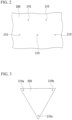
- FIG. 2 is a plan view of the thermal insulation film 200 as viewed from a direction orthogonal to a surface of the thermal insulation film 200.
- the thermal insulation film 200 has a hole portion 210.
- a convex portion 314 of the support member 300 to be described later is inserted into the hole portion 210.
- the size of the hole portion 210 may be any size as long as the convex portion 314 of the support member 300 can be inserted therethrough, and may be any size as long as light does not leak from the hole portion 210.
- the shape of the hole portion 210 is not particularly limited, and is preferably a circular shape, an elliptical shape, and the like in which a local force is not applied to the thermal insulation film 200.
- the thermal insulation film 200 may have, for example, a triangular shape as illustrated in FIG. 3 .
- the thermal insulation film 200 having a rectangular shape as illustrated in FIG. 4 may be employed.
- the hole portions 210 (210a to 210g) are provided in the vicinity of vertexes of the thermal insulation films 200, but the hole portions 210 may be provided not only at these positions but also at any position in the thermal insulation film 200.
- the plurality of hole portions 210 may be provided along an edge of the thermal insulation film 200 illustrated in FIG. 3 or FIG. 4 , and the hole portion 210 may be provided in a central portion of the thermal insulation film 200.
- the thermal insulation film 200 may be referred to as a radiation film.
- the support member 300 includes a first portion 310, a second portion 320, and one or more third portion 330.
- the first portion 310 and the second portion 320 are separated from each other, and the third portion 330 connects the first portion 310 and the second portion 320.
- the first portion 310 and the second portion 320 are disposed along a direction intersecting a surface of the thermal insulation film 200.
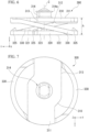
- FIG. 5 is a schematic side view of the support member 300 as viewed in a direction (Y-axis direction) orthogonal to an axis c of the support member.
- the axis c of the support member 300 means a line passing through the center of the support member 300 and orthogonal to an upper surface 311 of the first portion 310 in a case where the support member 300 is viewed from the side of the first portion 310.
- FIG. 6 is a schematic side view of the support member 300 as viewed in a direction (X-axis direction) orthogonal to the axis c of the support member.
- FIG. 7 is a schematic side view of the support member 300 as viewed in a direction (Z-axis direction) parallel to the axis c of the support member.
- the X-axis, the Y-axis, and the Z-axis in FIGS. 5 to 7 are orthogonal to each other.
- the Z-axis is parallel to the axis of the support member 300.
- the first portion 310 has the upper surface 311, a lower surface 312 provided on the opposite side of the upper surface 311, and a side portion 313 connecting the upper surface 311 and the lower surface 312.
- the upper surface 311 is a surface in contact with the thermal insulation film 200 when the thermal insulation structure 100 is formed.
- the lower surface 312 faces an upper surface 321 of the second portion 320 to be described later.
- the convex portion 314 is provided on the upper surface 311 of the first portion 310.
- the convex portion 314 is inserted into hole portion 210 of the thermal insulation film 200.
- the convex portion 314 may be engaged with a concave portion (not illustrated) provided in the second portion 320 to be described later.
- the second portion 320 has an upper surface 321, a lower surface 322 provided on the opposite side of the upper surface 321, and a side portion 323 connecting the upper surface 321 and the lower surface 322.
- the lower surface 322 is a surface in contact with the thermal insulation film 200 when the thermal insulation structure 100 is formed.
- the upper surface 321 faces the lower surface 312 of the first portion 310.
- the second portion 320 may be provided with a concave portion (not illustrated) that engages with the convex portion 314 provided on the upper surface 311 of the first portion 310.
- the support members 300 can be coupled to each other in the direction along the axis c of the support member 300.
- the convex portion 314 may be provided with a protruding portion 314a protruding in the outer diameter direction of the convex portion 314.
- the protruding portion 314a may be configured to be in contact with the upper surface 321 of the second portion 320 of the support member 300 to be coupled in a state where the convex portion 314 is inserted into the concave portion.
- the concave portion provided in the second portion 320 may be provided with a recess portion corresponding to the protruding portion 314a, and the protruding portion 314a and the recess portion may be configured to be engaged with each other.
- the third portion 330 connects the first portion 310 and the second portion 320.
- one end portion of the third portion 330 is connected to the side portion 313 of the first portion 310, and the other end portion of the third portion 330 is connected to the side portion 323 of the second portion 320.
- the length of the third portion 330 in the extending direction thereof is longer than the distance between the first portion 310 and the second portion 320.
- the distance between the first portion 310 and the second portion 320 is a distance D between the lower surface 312 of the first portion 310 and the upper surface 321 of the second portion 320 in a direction parallel to the axis c as illustrated in FIG. 5 .
- the distance D and the length of the third portion 330 in the extending direction are lengths in a state where no force is applied to the support member 300 (also referred to as an initial state).
- the extending direction of the third portion 330 means a direction in which the third portion 330 is continuous from one end side to the other end side of the third portion 330.
- the length of the third portion 330 in the extending direction is a length connecting centers of cross sections perpendicular to the extending direction at respective points in the extending direction.
- the shape of the cross section of the third portion 330 perpendicular to the extending direction at each point in the extending direction is not particularly limited, and may be circular, elliptical, or rectangular.
- the cross section of the third portion 330 perpendicular to the extending direction at each point in the extending direction is preferably smaller than the outer diameter of the support member 300. In the support member 300, since the third portion 330 connecting the first portion 310 and the second portion 320 is formed long in the extending direction, the thermal resistance of the support member 300 as a whole increases.
- the third portions 330 are paired and have a spiral shape. With such a shape, stability as the support member 300 is secured, and the support member 300 can be smoothly elastically deformed in a direction parallel to the axis c.
- the third portion 330 preferably does not protrude in the radial direction of the support member 300.
- the outer diameter of the third portion 330 forms the outer diameter of the entire support member 300.
- the third portion 330 is not limited to this shape, and may have a linear shape or a shape obtained by combining a plurality of linear shapes and curved shapes.
- the end portion of the third portion 330 may be connected to the lower surface 312 of the first portion 310 and the upper surface 321 of the second portion 320.
- the support member 300 is elastically deformable in a direction intersecting a surface of the thermal insulation film 200.
- the thermal insulation film 200 can be supported by the support member 300 in a state where tension is applied in an in-plane direction of the thermal insulation film 200. More specifically, since the support member 300 is elastically deformable in a direction parallel to axis c, the support member 300 is elastically deformable in a direction intersecting a surface of the thermal insulation film 200 when the thermal insulation structure 100 is formed.
- the support member 300 has a structure in which the first portion 310 and the second portion 320 are connected by the third portion 330 as described above, in a case where a compressive force in a direction parallel to the axis c is received, a part or the whole of the third portion 330 is deformed to reduce the interval between the first portion 310 and the second portion 320, and the support member 300 as a whole contracts in a direction parallel to the axis c.
- the third portion 330 in a case where a tensile force is applied in a direction parallel to the axis c, a part or the whole of the third portion 330 is deformed, by which the interval between the first portion 310 and the second portion 320 increases, and the support member 300 as a whole extends in a direction parallel to the axis c.
- the restoring force of the third portion 330 returns the interval between the first portion 310 and the second portion 320 to the initial state.
- the height of the support member 300 in the direction parallel to the axis c is preferably 1 mm or more because it is necessary and sufficient to prevent contact between the thermal insulation films 200.
- the height is preferably 5 mm or less since this allows the support member 300 to easily maintain a shape parallel to the axis c.
- an outer diameter of the support member 300 on a plane orthogonal to axis c is preferably 3 mm to 20 mm in order to ensure a contact surface sufficient for the thermal insulation film 200 and the support member 300 to transmit a compressive force or a tensile force.
- the height of the support member 300 means a distance h between the upper surface 311 of the first portion 310 and the lower surface 322 of the second portion 320 in a direction parallel to the axis c as illustrated in FIG. 6 .
- the support member 300 is preferably made of a resin material such as polyether ether ketone (PEEK), polycarbonate (PC), polyethylene terephthalate (PET), or polyimide (PI).
- PEEK polyether ether ketone
- PC polycarbonate
- PET polyethylene terephthalate
- PI polyimide
- the support member 300 is manufactured by injection molding raw materials of these resin materials.
- the configuration of the support member 300 is not limited to this, and may be made of any other appropriate material.
- Polyether ether ketone is the most preferable material as the support member 300 from the viewpoints of high heat resistance, low temperature embrittlement resistance, a small amount of outgas in a vacuum, and ultraviolet resistance required in a thermal insulation material for space transportation vehicles.
- the support members 300 may be coupled in a direction in which the thermal insulation films 200 are laminated.
- One or a plurality of the thermal insulation films 200 is sandwiched between the two support members 300 coupled to each other.
- the thermal insulation films 200a to 200f may be stacked between the coupled support members 300g and 300h.
- the support member 300 is preferably attached to the base body 10 such that a perpendicular line of the surface 11 of the base body 10 at a position where the support member 300 is attached coincides with the axis c of the support member 300. Therefore, in a case where the surface 11 of the base body 10 is a curved surface or a spherical surface, the axis c of the support member 300 is inclined with respect to the axis c of the adjacent support member 300.
- the second portion 320 may be provided with a protruding portion 325 facing the first portion 310. More specifically, the upper surface 321 of the second portion 320 is provided with the protruding portion 325 facing the lower surface 312 of the first portion 310.
- a strong compressive force acts on the thermal insulation structure 100 by being pressurized to atmospheric pressure, and the support member 300 is compressed and crushed as a whole.
- the thermal resistance of the support member 300 itself can be increased, and lighter and higher thermal insulation performance than that of a conventional foam thermal insulation material and the like can be obtained.
- the thermal insulation structure 100 moves from a pressurized environment to a vacuum environment and no compressive force due to pressurization acts, the elastic deformability of the support member 300 moves the first portion 310 and the second portion 320 in a direction separating from each other, by which the interval between the thermal insulation film layers relatively increases, and higher thermal insulation performance can be obtained.
- the shape of the base body 10 is not particularly limited, but for example, a part of it may be a curved surface or a spherical surface.
- the base body 10 is, for example, a propellant tank for storing a cryogenic fluid such as a national latest launch system, a structure such as an artificial satellite, or an inner wall of a vacuum tank on the ground. Since the thermal insulation structure 100 according to the present embodiment has high thermal insulation performance and is lightweight, the thermal insulation structure 100 according to the present embodiment can be preferably applied to these base bodies.
- FIG. 9 illustrates an application example of the thermal insulation structure 100 according to the present embodiment.
- the thermal insulation structure 100 is provided around a propellant tank (base body) 10a to form a structure 1.
- a plurality of thermal insulation films forms a thermal insulation film layer (thermal insulation film layer as an outermost layer).
- each layer of the thermal insulation film layer is formed by the plurality of thermal insulation films 200.
- the thermal insulation structure 100 can be formed along the shape of the base body.
- the plurality of thermal insulation films 200 having a triangular shape as illustrated in FIG. 3 is used.
- the support member 300 is compressed or stretched in a direction parallel to the axis c.
- the interval between the hole portions 210 of the thermal insulation film 200 as described above is appropriately designed.
- the support member 300 is contracted as compared with the initial state by designing the distance between the adjacent hole portions 210 to be small.
- a component of the stress ⁇ c acts in the in-plane direction of the thermal insulation film 200, and tension is applied to the thermal insulation film 200 between the adjacent support members 300.
- the support member 300 is elongated as compared with the initial state by designing the distance between the adjacent hole portions 210 to be small.
- h the height of the support member 300 in the initial state
- he the height of the support member 300 in the elongated state
- h > he is satisfied.
- tension is applied in the in-plane direction of the thermal insulation film 200 by the restoring force of the support member 300 to return to the initial state.
- an elastic coefficient in a direction parallel to the axis c of the support member 300 is k
- the position of the hole portion 210 is designed on condition that the thermal insulation structure 100 and the base body 10 are at room temperature (25°C) under atmospheric pressure.
- the arrangement of the support member 300 and the length of compression or stretching are appropriately designed such that the interval between the thermal insulation films 200 can be kept in a state of not being in contact with each other, and the arrangement of the thermal insulation film 200 and the hole portions 210 of the thermal insulation film 200 is determined in consideration of the temperature at the time of using each thermal insulation film layer, the temperature difference from room temperature, the deformation due to degassing in a vacuum state, the dimensional change when exposed to high temperature, and the like.
- the thermal insulation structure 100 can be preferably used for the base body 10 having a part or the whole formed in a curved surface or a spherical surface. Note that the thermal insulation structure 100 may be installed in a sealed space in a vacuum state.
- the thermal insulation film 200 is supported by the support member 300 in a state where tension is applied in the in-plane direction of the thermal insulation film 200, deflection of the thermal insulation film 200 is suppressed. Therefore, contact between the laminated thermal insulation films 200 can be suppressed, and thermal insulation performance can be improved.
- the length in the extending direction of the third portion 330 is longer than the distance between the first portion 310 and the second portion 320, the route through which heat is transferred in the support member 300 becomes longer, the heat conduction amount of the support member 300 can be reduced, and the thermal insulation performance of the thermal insulation structure 100 can be improved.
- the thermal insulation structure 100 since the contact between the laminated thermal insulation films 200 can be suppressed only by the support member 300, a member such as a nonwoven fabric or a mesh is unnecessary, and the mass of the thermal insulation structure 100 can be reduced.
- the support member 300 is elastically deformable in the direction intersecting the surface of the thermal insulation film 200, even in a case where the thermal insulation film 200 having a small thickness is used, an appropriate tension can be applied to the thermal insulation film 200, and the mass of the thermal insulation structure 100 can be reduced.
- the thermal insulation structure 100 In a case where the thermal insulation structure 100 according to the above embodiment is applied to a propellant tank of a national mini launch system, the outer surface has a high temperature due to the influence of sunlight and the like, and the inner surface has a relatively low temperature due to a fluid in the propellant tank.
- the fluid temperature in the propellant tank changes due to the remaining amount of the propellant and the pressure in the tank. Therefore, the temperature of the propellant tank itself or the thermal insulation structure 100 changes, and thermal distortion corresponding to each temperature difference occurs.
- the pressure in the propellant tank is changed, the tank expands.
- the thermal insulation film 200 may be bent or a cut portion may be provided in the thermal insulation film 200 such that the thermal insulation film 200 can be extended between the support members 300.
- the state in which at least a part of the thermal insulation film 200 is bent means that a part of the thermal insulation film 200 is bent in the in-plane direction as illustrated in FIG. 10(A) or 10(B) .
- a bent range of the thermal insulation film 200 is referred to as a bent portion 230.
- the bent portion 230 or the cut portion 250 is provided between the adjacent support members 300.
- the number of the bent portions 230 or the cut portions 250 is not particularly limited, but it is more preferable that the bent portions 230 or the cut portions 250 be provided on a line segment connecting the support member 300 and the support member 300. It is not necessary to provide the bent portion 230 or the cut portion 250 in the entire range of the thermal insulation structure 100, and it is preferable to appropriately set the arrangement of the bent portion 230 or the cut portion 250.
- a subfilm 400 laminated on the thermal insulation film 200 be further provided.
- the subfilm 400 is preferably sandwiched between the two support members 300 (300i and 300j) coupled together with the thermal insulation film 200 in a state of being stacked on the thermal insulation film 200.
- the subfilm 400 may be made of the same material as thermal insulation film 200, or may have the same thickness as thermal insulation film 200.
- the subfilm 400 may be made of a material thicker than the thermal insulation film 200, and the thickness of the subfilm 400 is preferably 6 ⁇ m to 100 ⁇ m from the viewpoint of imparting strength that does not damage the subfilm 400 even in a case where a bending force or a tensile force is applied to the subfilm 400.
- the shape of the subfilm 400 is not particularly limited, but may be, for example, a circular shape, an elliptical shape, or a belt shape.
- the subfilm 400 presses the thermal insulation film 200 in a direction intersecting a surface of the thermal insulation film 200, by which an interval between the laminated thermal insulation films 200 can be appropriately maintained.
- the end portion of the subfilm 400 may be folded back.
- the end portion of the subfilm is reinforced, and for example, even in a case where a thin subfilm 400 equivalent to the thermal insulation film 200 is adopted, strength sufficient for pressing the thermal insulation film 200 can be obtained.
- the end portion of the thermal insulation film 200 may be folded back.
- a function of pressing the thermal insulation film 200 such as the subfilm 400 can be imparted to the thermal insulation film 200 itself.
- a net spacer or an embossed film may be further provided between the thermal insulation films 200. Since the embossed film is superior in rigidity to a normal flat film, the arrangement interval of the support members 300 can be lengthened, and it is effective for both reducing the influence of contact between the thermal insulation films 200 and preventing contact. To reduce costs, the use of embossed films may be partial.
- a conductor layer may be provided on the surface of the support member 300.
- Such a conductor layer may be formed by nickel plating or aluminum vapor deposition.
- the emissivity of the surface of the support member 300 can be reduced, and thermal insulation performance can be further improved by suppressing radiation heat transfer from the surface of the support member 300.
- the above conductor layer may be provided only on some of the support members 300.
- the conditions in the example are examples relating to one condition adopted to confirm the feasibility and effects of the present invention, but the present invention is not limited to this example.
- the present invention can adopt various conditions as long as the object of the present invention is achieved without departing from the gist of the present invention.
- the thermal insulation structure described in the above embodiment was attached to a surface of a tank installed in a vacuum container, liquid nitrogen (LN 2 ) was stored in the tank, and a mass flow rate of vapor generated from the inside of the tank was measured to evaluate heat entering from the thermal insulation structure.
- a guard tank that individually removes heat by evaporation was set not to be affected by heat entering through a portion other than the thermal insulation structure such as a pipe.
- the outline of the test apparatus is illustrated in FIG. 13 .
- FIG. 14 illustrates a state in which the thermal insulation structure according to the present invention was attached to a test tank.
- Most of the surface of the propellant tank of the spacecraft was a combination of an elliptical sphere and a tube, and FIG. 14 is an example when the thermal insulation structure according to the present invention was attached to the elliptical sphere portion. It is understood from FIG. 14 that the present invention is also applicable to a spherical surface.
- FIG. 15 illustrates an example of performance when the structure of the thermal insulation structure according to the present invention was adopted and 12 radiation films of aluminum vapor-deposited polyester were stacked as thermal insulation films.
- the result of FIG. 15 illustrates the heat flux in a case where the low temperature side of the inner layer of the thermal insulation material was the liquid nitrogen temperature (77 K).
- the heat flux when the thermal insulation structure according to the present invention was applied to the elliptical spherical surface is indicated by a triangular plot ( ⁇ ).
- the triangular plot is in the same range as the result (circle plot (•) and error bar) when the thermal insulation structure was installed in the tubular portion, and it could be seen that the thermal insulation structure according to the present invention can be applied as a thermal insulation material for a propellant tank without being affected by the shape of an elliptical sphere, a tube, and the like.
- the vertical axis represents the passage heat flux (W/m 2 )
- the horizontal axis represents the hightemperature side boundary temperature (K).
- Table 1 illustrates the results of comparing the performance of the thermal insulation structure (Example 1) according to the present invention at an outer layer temperature of 300 K with a thermal insulation structure of Comparative Example 1, which was a multilayer thermal insulation material having 20 layers of radiation films, and a thermal insulation structure of Comparative Example 2 including a foam thermal insulation material having a thickness of 25 mm.
- the thermal insulation structure used in Comparative Example 1 was different from that of Example 1 in that the members that support the radiation films are not elastically deformed.
- a plurality of foam thermal insulation materials was stacked to form a thermal insulation structure.
- Example 1 Comparative Example 1 Comparative Example 2 Thermal insulation material performance Heat flux (W/m 2 ) 0.78 1.30 134 Area density (kg/m 2 ) 0.31 1.50 0.84 When spherical tank is assumed LN 2 evaporation rate (%/day) 0.13 0.21 21.7 LN 2 evaporation amount (kg/day) 4.3 7.1 731 Thermal insulation material mass (kg) 3.9 19 11
- Table 1 illustrates the results of calculation of the evaporation rate and evaporation amount of liquid nitrogen and the total mass as the insulation structure when each thermal insulation structure was applied to a spherical tank having a diameter of 2 m.
- the thermal insulation structure of Example 1 had high thermal insulation performance, the thermal insulation performance could be secured without increasing the area density. Therefore, it can be seen that in a case where the thermal insulation structure of Example 1 was applied to a spherical tank, the evaporation amount of a substance (liquid nitrogen in this example) stored in the tank could be suppressed, and the mass as the thermal insulation structure could also be reduced.
- the present invention it is possible to provide a lightweight thermal insulation structure having high thermal insulation performance, and a structure including the thermal insulation structure. Therefore, the industrial value is extremely high.
Landscapes
- Engineering & Computer Science (AREA)
- General Engineering & Computer Science (AREA)
- Mechanical Engineering (AREA)
- Remote Sensing (AREA)
- Aviation & Aerospace Engineering (AREA)
- Chemical & Material Sciences (AREA)
- Combustion & Propulsion (AREA)
- Physics & Mathematics (AREA)
- Thermal Sciences (AREA)
- Health & Medical Sciences (AREA)
- Critical Care (AREA)
- Emergency Medicine (AREA)
- General Health & Medical Sciences (AREA)
- Thermal Insulation (AREA)
Abstract
Description
- The present invention relates to a thermal insulation structure and a structure including the thermal insulation structure.
- Since a propellant tank for storing a cryogenic fluid such as a national flagship launch system is required to be lightweight, a foam thermal insulation material is used as a thermal insulation material surrounding the propellant tank. However, the foam thermal insulation material has a low thermal insulation performance, and has a problem in that an evaporation rate of a cryogenic propellant such as liquid hydrogen cannot be suppressed. On the other hand, a cryogenic storage tank on the ground in which the evaporation rate is suppressed has a structure in which multilayer insulation (MLI) is provided in a vacuum double container.
- In the conventional MLI, thermal insulation performance is secured by stacking a plurality of thermal insulation films in layers to lessen heat transfer due to radiation, and reducing a contact portion between the thermal insulation films with a nonwoven fabric or a mesh to reduce heat transfer due to heat conduction. For example, in the technique of
Patent Document 1, a thick thermal insulation film is adopted to maintain the structure in order to maintain the interval between the thermal insulation films. In addition, Patent Document 2 discloses an MLI in which heat conduction is reduced by installing a spacer instead of a nonwoven fabric or a mesh. - Patent Document 3 discloses a technique related to a lightweight thermal insulation material for cryogenic storage intended for use in space. In the technique of Patent Document 3, the MLI is kept in a vacuum state even in the atmosphere by covering the thermal insulation material with a vacuum pack. In this technique, when moving to a vacuum environment such as in orbit, external pressure such as atmospheric pressure disappears, and a spring mechanism installed in the MLI expands to reduce heat conduction, by which thermal insulation performance is further improved.
-
- [Patent Document 1]
United States Patent Publication No. 2017/0073090 - [Patent Document 2]
United States Patent No. 8234835 - [Patent Document 3]
Japanese Unexamined Patent First Publication No. 2019-094016 - However, in the MLI using a nonwoven fabric or a mesh as disclosed in
Patent Document 1 or the MLI using a spacer as disclosed in Patent Document 2, there is a problem in that the contact state of the thermal insulation film changes according to an error at the time of construction, an acceleration environment, or an operation situation of the propellant tank, and the thermal insulation performance cannot be managed. In a case where the thermal insulation performance is low, it is conceivable to increase the total number of thermal insulation films (the number of layers) of MLI as a countermeasure, but when the total number of thermal insulation films is increased, MLI becomes thicker by an amount corresponding to the total number of thermal insulation films, by which a force to press the layers is generated in the bent portion due to a difference between the inside and the outside of the layer, and the thermal insulation performance is deteriorated. Furthermore, the possibility of contact between the thermal insulation films increases due to the increased weight load of the thermal insulation films. Therefore, increasing the total number of MLIs is not a direct countermeasure against performance deterioration due to contact between the thermal insulation films particularly in an environment receiving acceleration. In addition, the structure as disclosed in Patent Document 3 is a mechanism that partially breaks a component under atmospheric pressure, and focuses on thermal insulation performance when a pressurized environment is shifted to a vacuum environment. - In view of the above circumstances, an object of the present invention is to provide a lightweight thermal insulation structure having high thermal insulation performance, and a structure including the thermal insulation structure.
- When the MLI is used as a thermal insulation material of a cryogenic propellant tank of a space transportation vehicle, a load environment changes due to its own weight due to acceleration such as engine thrust, or due to expansion or contraction of the tank due to pressurization or a change in surface temperature. At these times, the present inventors have focused on the fact that since the interval between the thermal insulation films held by a nonwoven fabric, a mesh, or a spacer is narrowed, contact occurs between the thermal insulation films, and heat transfer due to heat conduction increases.
- As a result, the present inventors have found that it is possible to realize a lightweight thermal insulation structure having high thermal insulation performance by supporting the thermal insulation film by an elastically deformable support member in a state where tension is applied to the thermal insulation film forming the MLI. The present invention has been made based on such findings, and the gist is as follows.
-
- (1) A thermal insulation structure according to one aspect of the present invention includes:
- a thermal insulation film; and
- a plurality of support members that supports the thermal insulation film, in which
- the thermal insulation film is supported by the support member in a state where tension is applied in an in-plane direction of the thermal insulation film,
- the support member includes a first portion and a second portion that are separated from each other, and one or more third portion that connects the first portion and the second portion, and a length of the third portion in an extending direction of the third portion is longer than a distance between the first portion and the second portion,
- the first portion and the second portion are disposed along a direction intersecting a surface of the thermal insulation film, and
- the support member is elastically deformable in the direction intersecting the surface of the thermal insulation film.
- (2) In the thermal insulation structure according to (1),
at least a part of the thermal insulation film may be bent or the thermal insulation film may be provided with a cut portion by which the thermal insulation film is capable of being extended between the support members. - (3) In the thermal insulation structure according to (1) or (2),
a subfilm laminated on the thermal insulation film may be further provided, and the subfilm may press the thermal insulation film in the direction intersecting the surface of the thermal insulation film. - (4) In the thermal insulation structure according to any one of (1) to (3),
the thermal insulation film may have a hole portion, a convex portion may be provided in the first portion of the support member, and the thermal insulation film may be supported in a state where the convex portion is inserted into the hole portion. - (5) In the thermal insulation structure according to any one of (1) to (4),
the thermal insulation film may be laminated with the support member interposed between. - (6) In the thermal insulation structure according to any one of (1) to (5),
the support member may be made of a resin material. - (7) In the thermal insulation structure according to any one of (1) to (6),
the second portion of the support member may be provided with a protruding portion facing the first portion. - (8) A structure according to one aspect of the present invention includes: a thermal insulation structure according to any one of (1) to (7); and a base body.
- According to the present invention, it is possible to provide a lightweight thermal insulation structure having high thermal insulation performance, and a structure including the thermal insulation structure.
-
-
FIG. 1 is a view explaining a thermal insulation structure according to an embodiment of the present invention, and is a schematic cross-sectional view of the thermal insulation structure viewed in a direction parallel to a surface of a thermal insulation film forming the thermal insulation structure. -
FIG. 2 is a view explaining a thermal insulation film according to an embodiment of the present invention, and is a schematic plan view of the thermal insulation film viewed from a direction orthogonal to a surface of the thermal insulation film. -
FIG. 3 is a view explaining an example of a shape of the thermal insulation film according to an embodiment of the present invention, and is a schematic plan view of the thermal insulation film viewed from a direction orthogonal to a surface of the thermal insulation film. -
FIG. 4 is a view explaining an example of a shape of the thermal insulation film according to an embodiment of the present invention, and is a schematic plan view of the thermal insulation film viewed from a direction orthogonal to a surface of the thermal insulation film. -
FIG. 5 is a schematic side view of a support member according to an embodiment of the present invention as viewed in a direction (Y-axis direction) orthogonal to an axis of the support member. -
FIG. 6 is a schematic side view of the support member according to an embodiment of the present invention as viewed in a direction (X-axis direction) orthogonal to the axis of the support member. -
FIG. 7 is a schematic plan view of the support member according to an embodiment of the present invention as viewed in a direction (Z-axis direction) parallel to the axis of the support member. -
FIG. 8 is a view explaining a state in which a plurality of thermal insulation films is stacked, and is a schematic cross-sectional view of the thermal insulation structure viewed in a direction parallel to a surface of the thermal insulation film forming the thermal insulation structure. -
FIG. 9 is a schematic perspective view illustrating an example in which the thermal insulation structure according to an embodiment of the present invention is applied to a propellant tank. -
FIG. 10(A) is a view explaining a modification of a thermal insulation film provided with a bent portion, and is a plan view of a part of the thermal insulation film as viewed from a direction intersecting a surface of the thermal insulation film.FIG. 10(B) is a cross-sectional view of the thermal insulation film ofFIG. 10(A) as viewed in an in-plane direction of the thermal insulation film. -
FIG. 11(A) is a view explaining a modification of a thermal insulation film provided with a cut portion, and is a plan view of a part of the thermal insulation film as viewed from a direction intersecting a surface of the thermal insulation film.FIG. 10(B) is a plan view of a state in which a tensile force is applied to the thermal insulation film ofFIG. 10(A) . -
FIG. 12 is a view explaining a state in which a subfilm is further provided in the thermal insulation structure, and is a schematic cross-sectional view of the thermal insulation structure viewed in a direction parallel to a surface of the thermal insulation film forming the thermal insulation structure. -
FIG. 13 is a schematic view explaining an outline of a test apparatus according to an example. -
FIG. 14 is a photograph of the test apparatus according to an example. -
FIG. 15 is a graph explaining a measurement result according to an example. - Hereinafter, preferred embodiments of the present invention will be described in detail. However, the present invention is not limited only to the configuration disclosed in the present embodiments, and various modifications can be made without departing from the gist of the present invention. In the following description, specific numerical values and materials may be exemplified, but other numerical values and materials may be applied as long as the effect of the present invention can be obtained. In addition, components of the following embodiments can be combined with each other. In addition, the numerical limit range in the following embodiments includes a lower limit value and an upper limit value. A numerical value indicated as "more than" or "less than" is not included in the numerical range.
-
FIG. 1 is a schematic cross-sectional view of athermal insulation structure 100 according to the present embodiment viewed in a direction parallel to a surface of athermal insulation film 200 forming thethermal insulation structure 100. As illustrated inFIG. 1 , thethermal insulation structure 100 according to the present embodiment includes thethermal insulation film 200 and a plurality of support members 300 (300a to 300f) that supports thethermal insulation film 200. In the example ofFIG. 1 , thethermal insulation structure 100 is provided on asurface 11 of abase body 10 via the support members 300 (300d to 300f). - The
thermal insulation film 200 is supported by thesupport member 300 in a state where tension is applied in an in-plane direction of thethermal insulation film 200. - The
thermal insulation film 200 is a low-emissivity film capable of suppressing heat transfer due to radiation. Thethermal insulation film 200 is not particularly limited, but is formed by depositing a metal such as aluminum, gold, germanium, or conductive indium tin oxide (ITO) on a resin film such as polyimide or polyester. Thethermal insulation film 200 is not limited to this, and can be made of any other suitable material as long as it can withstand the tension applied to thethermal insulation film 200. The thickness of thethermal insulation film 200 is preferably 6 µm or more, and more preferably 12 µm or more from the viewpoint of preventing damage to thethermal insulation film 200 such as elongation and breakage due to application of tension. In addition, the thickness of thethermal insulation film 200 is preferably 200 µm or less, and more preferably 25 µm or less, from the viewpoint of realizing a lightweight structure and suppressing the weight of thethermal insulation film 200. The thickness of thethermal insulation film 200 is an average value (arithmetic average value) of thicknesses measured at four arbitrary points by a dial gauge. - The
thermal insulation film 200 is laminated with thesupport member 300 to be described later interposed between. In the example ofFIG. 1 , a form in which two thermal insulation film layers 20a and 20b are formed by twothermal insulation films 200 is exemplified, but the thermal insulation film layer forming thethermal insulation structure 100 may be one layer. In addition, three, four, five, or six or more thermal insulation film layers may be laminated. The plurality ofthermal insulation films 200 may form one thermal insulation film layer. Here, for example, in a case where there are two thermal insulation film layers, there are two or morethermal insulation films 200 laminated with thesupport member 300 interposed between. -
FIG. 2 is a plan view of thethermal insulation film 200 as viewed from a direction orthogonal to a surface of thethermal insulation film 200. Thethermal insulation film 200 has ahole portion 210. Aconvex portion 314 of thesupport member 300 to be described later is inserted into thehole portion 210. The size of thehole portion 210 may be any size as long as theconvex portion 314 of thesupport member 300 can be inserted therethrough, and may be any size as long as light does not leak from thehole portion 210. The shape of thehole portion 210 is not particularly limited, and is preferably a circular shape, an elliptical shape, and the like in which a local force is not applied to thethermal insulation film 200. - The
thermal insulation film 200 may have, for example, a triangular shape as illustrated inFIG. 3 . In addition, thethermal insulation film 200 having a rectangular shape as illustrated inFIG. 4 may be employed. In thethermal insulation film 200 illustrated inFIG. 3 orFIG. 4 , the hole portions 210 (210a to 210g) are provided in the vicinity of vertexes of thethermal insulation films 200, but thehole portions 210 may be provided not only at these positions but also at any position in thethermal insulation film 200. For example, the plurality ofhole portions 210 may be provided along an edge of thethermal insulation film 200 illustrated inFIG. 3 orFIG. 4 , and thehole portion 210 may be provided in a central portion of thethermal insulation film 200. Note that thethermal insulation film 200 may be referred to as a radiation film. - Next, the
support member 300 will be described. As illustrated inFIG. 1 , thesupport member 300 includes afirst portion 310, asecond portion 320, and one or morethird portion 330. Thefirst portion 310 and thesecond portion 320 are separated from each other, and thethird portion 330 connects thefirst portion 310 and thesecond portion 320. As illustrated inFIG. 1 , thefirst portion 310 and thesecond portion 320 are disposed along a direction intersecting a surface of thethermal insulation film 200. -
FIG. 5 is a schematic side view of thesupport member 300 as viewed in a direction (Y-axis direction) orthogonal to an axis c of the support member. Here, the axis c of thesupport member 300 means a line passing through the center of thesupport member 300 and orthogonal to anupper surface 311 of thefirst portion 310 in a case where thesupport member 300 is viewed from the side of thefirst portion 310.FIG. 6 is a schematic side view of thesupport member 300 as viewed in a direction (X-axis direction) orthogonal to the axis c of the support member.FIG. 7 is a schematic side view of thesupport member 300 as viewed in a direction (Z-axis direction) parallel to the axis c of the support member. The X-axis, the Y-axis, and the Z-axis inFIGS. 5 to 7 are orthogonal to each other. The Z-axis is parallel to the axis of thesupport member 300. - The
first portion 310 has theupper surface 311, alower surface 312 provided on the opposite side of theupper surface 311, and aside portion 313 connecting theupper surface 311 and thelower surface 312. Theupper surface 311 is a surface in contact with thethermal insulation film 200 when thethermal insulation structure 100 is formed. Thelower surface 312 faces anupper surface 321 of thesecond portion 320 to be described later. - The
convex portion 314 is provided on theupper surface 311 of thefirst portion 310. Theconvex portion 314 is inserted intohole portion 210 of thethermal insulation film 200. In addition, theconvex portion 314 may be engaged with a concave portion (not illustrated) provided in thesecond portion 320 to be described later. - The
second portion 320 has anupper surface 321, alower surface 322 provided on the opposite side of theupper surface 321, and aside portion 323 connecting theupper surface 321 and thelower surface 322. Thelower surface 322 is a surface in contact with thethermal insulation film 200 when thethermal insulation structure 100 is formed. Theupper surface 321 faces thelower surface 312 of thefirst portion 310. - The
second portion 320 may be provided with a concave portion (not illustrated) that engages with theconvex portion 314 provided on theupper surface 311 of thefirst portion 310. Thus, thesupport members 300 can be coupled to each other in the direction along the axis c of thesupport member 300. Theconvex portion 314 may be provided with a protrudingportion 314a protruding in the outer diameter direction of theconvex portion 314. In a case where the concave portion provided in thesecond portion 320 penetrates from theupper surface 321 toward thelower surface 322 of thesecond portion 320, the protrudingportion 314a may be configured to be in contact with theupper surface 321 of thesecond portion 320 of thesupport member 300 to be coupled in a state where theconvex portion 314 is inserted into the concave portion. In addition, the concave portion provided in thesecond portion 320 may be provided with a recess portion corresponding to the protrudingportion 314a, and the protrudingportion 314a and the recess portion may be configured to be engaged with each other. - The
third portion 330 connects thefirst portion 310 and thesecond portion 320. In the example ofFIG. 5 , one end portion of thethird portion 330 is connected to theside portion 313 of thefirst portion 310, and the other end portion of thethird portion 330 is connected to theside portion 323 of thesecond portion 320. - In the
support member 300, the length of thethird portion 330 in the extending direction thereof is longer than the distance between thefirst portion 310 and thesecond portion 320. Here, the distance between thefirst portion 310 and thesecond portion 320 is a distance D between thelower surface 312 of thefirst portion 310 and theupper surface 321 of thesecond portion 320 in a direction parallel to the axis c as illustrated inFIG. 5 . The distance D and the length of thethird portion 330 in the extending direction are lengths in a state where no force is applied to the support member 300 (also referred to as an initial state). The extending direction of thethird portion 330 means a direction in which thethird portion 330 is continuous from one end side to the other end side of thethird portion 330. The length of thethird portion 330 in the extending direction is a length connecting centers of cross sections perpendicular to the extending direction at respective points in the extending direction. The shape of the cross section of thethird portion 330 perpendicular to the extending direction at each point in the extending direction is not particularly limited, and may be circular, elliptical, or rectangular. The cross section of thethird portion 330 perpendicular to the extending direction at each point in the extending direction is preferably smaller than the outer diameter of thesupport member 300. In thesupport member 300, since thethird portion 330 connecting thefirst portion 310 and thesecond portion 320 is formed long in the extending direction, the thermal resistance of thesupport member 300 as a whole increases. - In the example of
FIG. 5 and the like, thethird portions 330 are paired and have a spiral shape. With such a shape, stability as thesupport member 300 is secured, and thesupport member 300 can be smoothly elastically deformed in a direction parallel to the axis c. In addition, when thesupport member 300 is viewed from a direction parallel to the axis c, thethird portion 330 preferably does not protrude in the radial direction of thesupport member 300. For example, in the example ofFIG. 7 , when thesupport member 300 is viewed from the direction parallel to the axis c, the outer diameter of thethird portion 330 forms the outer diameter of theentire support member 300. With such a configuration, contact between thethermal insulation film 200 and thesupport member 300 when thethermal insulation film 200 is deflected can be suppressed, by which deterioration of thermal insulation performance as thethermal insulation structure 100 can be suppressed. However, thethird portion 330 is not limited to this shape, and may have a linear shape or a shape obtained by combining a plurality of linear shapes and curved shapes. In addition, the end portion of thethird portion 330 may be connected to thelower surface 312 of thefirst portion 310 and theupper surface 321 of thesecond portion 320. - The
support member 300 is elastically deformable in a direction intersecting a surface of thethermal insulation film 200. Thus, thethermal insulation film 200 can be supported by thesupport member 300 in a state where tension is applied in an in-plane direction of thethermal insulation film 200. More specifically, since thesupport member 300 is elastically deformable in a direction parallel to axis c, thesupport member 300 is elastically deformable in a direction intersecting a surface of thethermal insulation film 200 when thethermal insulation structure 100 is formed. Since thesupport member 300 has a structure in which thefirst portion 310 and thesecond portion 320 are connected by thethird portion 330 as described above, in a case where a compressive force in a direction parallel to the axis c is received, a part or the whole of thethird portion 330 is deformed to reduce the interval between thefirst portion 310 and thesecond portion 320, and thesupport member 300 as a whole contracts in a direction parallel to the axis c. In addition, in a case where a tensile force is applied in a direction parallel to the axis c, a part or the whole of thethird portion 330 is deformed, by which the interval between thefirst portion 310 and thesecond portion 320 increases, and thesupport member 300 as a whole extends in a direction parallel to the axis c. In addition, when these compressive forces or tensile forces are no longer applied, the restoring force of thethird portion 330 returns the interval between thefirst portion 310 and thesecond portion 320 to the initial state. - The height of the
support member 300 in the direction parallel to the axis c is preferably 1 mm or more because it is necessary and sufficient to prevent contact between thethermal insulation films 200. In addition, the height is preferably 5 mm or less since this allows thesupport member 300 to easily maintain a shape parallel to the axis c. In addition, an outer diameter of thesupport member 300 on a plane orthogonal to axis c is preferably 3 mm to 20 mm in order to ensure a contact surface sufficient for thethermal insulation film 200 and thesupport member 300 to transmit a compressive force or a tensile force. The height of thesupport member 300 means a distance h between theupper surface 311 of thefirst portion 310 and thelower surface 322 of thesecond portion 320 in a direction parallel to the axis c as illustrated inFIG. 6 . - The
support member 300 is preferably made of a resin material such as polyether ether ketone (PEEK), polycarbonate (PC), polyethylene terephthalate (PET), or polyimide (PI). For example, thesupport member 300 is manufactured by injection molding raw materials of these resin materials. The configuration of thesupport member 300 is not limited to this, and may be made of any other appropriate material. Polyether ether ketone is the most preferable material as thesupport member 300 from the viewpoints of high heat resistance, low temperature embrittlement resistance, a small amount of outgas in a vacuum, and ultraviolet resistance required in a thermal insulation material for space transportation vehicles. - As illustrated in
FIG. 1 , thesupport members 300 may be coupled in a direction in which thethermal insulation films 200 are laminated. One or a plurality of thethermal insulation films 200 is sandwiched between the twosupport members 300 coupled to each other. For example, in a case where one thermal insulation film layer is formed by the plurality ofthermal insulation films 200, as illustrated inFIG. 8 , thethermal insulation films 200a to 200f may be stacked between the coupledsupport members - In order to efficiently transmit the force applied to the
support member 300 to thebase body 10, thesupport member 300 is preferably attached to thebase body 10 such that a perpendicular line of thesurface 11 of thebase body 10 at a position where thesupport member 300 is attached coincides with the axis c of thesupport member 300. Therefore, in a case where thesurface 11 of thebase body 10 is a curved surface or a spherical surface, the axis c of thesupport member 300 is inclined with respect to the axis c of theadjacent support member 300. - In the
support member 300, as illustrated inFIG. 5 orFIG. 6 , thesecond portion 320 may be provided with a protrudingportion 325 facing thefirst portion 310. More specifically, theupper surface 321 of thesecond portion 320 is provided with the protrudingportion 325 facing thelower surface 312 of thefirst portion 310. For example, under a pressurized environment such as on the ground, a strong compressive force acts on thethermal insulation structure 100 by being pressurized to atmospheric pressure, and thesupport member 300 is compressed and crushed as a whole. By providing the protrudingportion 325, the contact area between thefirst portion 310 and thesecond portion 320 when compressed and crushed is minimized, the thermal resistance of thesupport member 300 itself can be increased, and lighter and higher thermal insulation performance than that of a conventional foam thermal insulation material and the like can be obtained. When thethermal insulation structure 100 moves from a pressurized environment to a vacuum environment and no compressive force due to pressurization acts, the elastic deformability of thesupport member 300 moves thefirst portion 310 and thesecond portion 320 in a direction separating from each other, by which the interval between the thermal insulation film layers relatively increases, and higher thermal insulation performance can be obtained. - The shape of the
base body 10 is not particularly limited, but for example, a part of it may be a curved surface or a spherical surface. Thebase body 10 is, for example, a propellant tank for storing a cryogenic fluid such as a national flagship launch system, a structure such as an artificial satellite, or an inner wall of a vacuum tank on the ground. Since thethermal insulation structure 100 according to the present embodiment has high thermal insulation performance and is lightweight, thethermal insulation structure 100 according to the present embodiment can be preferably applied to these base bodies. -
FIG. 9 illustrates an application example of thethermal insulation structure 100 according to the present embodiment. In the example ofFIG. 9 , thethermal insulation structure 100 is provided around a propellant tank (base body) 10a to form astructure 1. In the example ofFIG. 9 , a plurality of thermal insulation films forms a thermal insulation film layer (thermal insulation film layer as an outermost layer). In a case where thethermal insulation structure 100 according to the present embodiment is provided on a base body having a shape as illustrated inFIG. 9 , each layer of the thermal insulation film layer is formed by the plurality ofthermal insulation films 200. Thus, thethermal insulation structure 100 can be formed along the shape of the base body. In the example ofFIG. 9 , the plurality ofthermal insulation films 200 having a triangular shape as illustrated inFIG. 3 is used. - In order to apply tension to the
thermal insulation film 200, when thethermal insulation structure 100 is installed on thebase body 10, thesupport member 300 is compressed or stretched in a direction parallel to the axis c. In order to realize such a state, the interval between thehole portions 210 of thethermal insulation film 200 as described above is appropriately designed. For example, in a case where thethermal insulation structure 100 according to the present embodiment is provided at a position where thesurface 11 of thebase body 10 becomes convex toward the outside of thebase body 10, thesupport member 300 is contracted as compared with the initial state by designing the distance between theadjacent hole portions 210 to be small. When the height of thesupport member 300 in the direction parallel to the axis c in the initial state is h and the height of thesupport member 300 in the contracted state is he, h > he is satisfied. In this case, tension is applied in the in-plane direction of thethermal insulation film 200 by a restoring force of thesupport member 300 to return to the initial state. Specifically, assuming that an elastic coefficient in a direction parallel to the axis c of thesupport member 300 is k, in a state where thesupport member 300 is contracted, a stress of σc = k (h - hc) is generated in a direction parallel to the axis c of thesupport member 300 and in which thefirst portion 310 and thesecond portion 320 are separated from each other. Since the axis c of thesupport member 300 is inclined with respect to the axis c of theadjacent support member 300, a component of the stress σc acts in the in-plane direction of thethermal insulation film 200, and tension is applied to thethermal insulation film 200 between theadjacent support members 300. - In addition, in a case where the
thermal insulation structure 100 according to the present embodiment is provided at a position where thesurface 11 of thebase body 10 becomes concave toward the inside of thebase body 10, thesupport member 300 is elongated as compared with the initial state by designing the distance between theadjacent hole portions 210 to be small. When the height of thesupport member 300 in the initial state is h and the height of thesupport member 300 in the elongated state is he, h > he is satisfied. In this case, tension is applied in the in-plane direction of thethermal insulation film 200 by the restoring force of thesupport member 300 to return to the initial state. Specifically, assuming that an elastic coefficient in a direction parallel to the axis c of thesupport member 300 is k, in a state where thesupport member 300 is elongated, a stress of σe = k (he - h) is generated in a direction parallel to the axis c of thesupport member 300 and in which thefirst portion 310 and thesecond portion 320 approach each other. Since the axis c of thesupport member 300 is inclined with respect to the axis c of theadjacent support member 300, a component of the stress σe acts in the in-plane direction of thethermal insulation film 200, and tension is applied to thethermal insulation film 200 between theadjacent support members 300. - Note that the position of the
hole portion 210 is designed on condition that thethermal insulation structure 100 and thebase body 10 are at room temperature (25°C) under atmospheric pressure. For example, the arrangement of thesupport member 300 and the length of compression or stretching are appropriately designed such that the interval between thethermal insulation films 200 can be kept in a state of not being in contact with each other, and the arrangement of thethermal insulation film 200 and thehole portions 210 of thethermal insulation film 200 is determined in consideration of the temperature at the time of using each thermal insulation film layer, the temperature difference from room temperature, the deformation due to degassing in a vacuum state, the dimensional change when exposed to high temperature, and the like. - From the above, the
thermal insulation structure 100 according to the present embodiment can be preferably used for thebase body 10 having a part or the whole formed in a curved surface or a spherical surface. Note that thethermal insulation structure 100 may be installed in a sealed space in a vacuum state. - In the
thermal insulation structure 100 according to the present embodiment, since thethermal insulation film 200 is supported by thesupport member 300 in a state where tension is applied in the in-plane direction of thethermal insulation film 200, deflection of thethermal insulation film 200 is suppressed. Therefore, contact between the laminatedthermal insulation films 200 can be suppressed, and thermal insulation performance can be improved. In addition, since the length in the extending direction of thethird portion 330 is longer than the distance between thefirst portion 310 and thesecond portion 320, the route through which heat is transferred in thesupport member 300 becomes longer, the heat conduction amount of thesupport member 300 can be reduced, and the thermal insulation performance of thethermal insulation structure 100 can be improved. - In addition, in the
thermal insulation structure 100 according to the present embodiment, since the contact between the laminatedthermal insulation films 200 can be suppressed only by thesupport member 300, a member such as a nonwoven fabric or a mesh is unnecessary, and the mass of thethermal insulation structure 100 can be reduced. In addition, since thesupport member 300 is elastically deformable in the direction intersecting the surface of thethermal insulation film 200, even in a case where thethermal insulation film 200 having a small thickness is used, an appropriate tension can be applied to thethermal insulation film 200, and the mass of thethermal insulation structure 100 can be reduced. - In a case where the
thermal insulation structure 100 according to the above embodiment is applied to a propellant tank of a national flagship launch system, the outer surface has a high temperature due to the influence of sunlight and the like, and the inner surface has a relatively low temperature due to a fluid in the propellant tank. The fluid temperature in the propellant tank changes due to the remaining amount of the propellant and the pressure in the tank. Therefore, the temperature of the propellant tank itself or thethermal insulation structure 100 changes, and thermal distortion corresponding to each temperature difference occurs. In addition, in a case where the pressure in the propellant tank is changed, the tank expands. By further providing the following structure, it is possible to preferably maintain the interval between the laminatedthermal insulation films 200 against such a change in temperature environment and a dimensional change of the propellant tank (base body). - In the
thermal insulation structure 100 according to the above embodiment, at least a part of thethermal insulation film 200 may be bent or a cut portion may be provided in thethermal insulation film 200 such that thethermal insulation film 200 can be extended between thesupport members 300. - The state in which at least a part of the
thermal insulation film 200 is bent means that a part of thethermal insulation film 200 is bent in the in-plane direction as illustrated inFIG. 10(A) or 10(B) . As described above, a bent range of thethermal insulation film 200 is referred to as abent portion 230. With such a configuration, in a case where a tensile force acts in the P direction inFIG. 10(A) or FIG. 10(B) , even in a case where expansion and contraction of the base body due to temperature change of the base body, expansion and contraction of thethermal insulation film 200 itself due to ambient temperature change, and design tolerance/error are occurred, the expansion and contraction and tolerance/error are absorbed by thebent portion 230 by stretching of thebent portion 230, and it is possible to suppress the occurrence of an excessive load on thesupport member 300. - In addition, as illustrated in
FIG. 11(A) , since acut portion 250 is provided in thethermal insulation film 200, in a case where a tensile force acts in the P direction inFIG. 11(A) , even in a case where expansion and contraction of the base body due to temperature change of the base body, expansion and contraction of thethermal insulation film 200 itself due to ambient temperature change, and design tolerance/error are occurred, the expansion and contraction and tolerance/error are absorbed by deformation of thecut portion 250 by expanding of thecut portion 250 as illustrated inFIG. 11(B) , and it is possible to suppress the occurrence of an excessive load on thesupport member 300. - The
bent portion 230 or thecut portion 250 is provided between theadjacent support members 300. The number of thebent portions 230 or thecut portions 250 is not particularly limited, but it is more preferable that thebent portions 230 or thecut portions 250 be provided on a line segment connecting thesupport member 300 and thesupport member 300. It is not necessary to provide thebent portion 230 or thecut portion 250 in the entire range of thethermal insulation structure 100, and it is preferable to appropriately set the arrangement of thebent portion 230 or thecut portion 250. - In the
thermal insulation structure 100 according to the above embodiment, as illustrated inFIG. 12 , it is preferable that asubfilm 400 laminated on thethermal insulation film 200 be further provided. Thesubfilm 400 is preferably sandwiched between the two support members 300 (300i and 300j) coupled together with thethermal insulation film 200 in a state of being stacked on thethermal insulation film 200. Thesubfilm 400 may be made of the same material asthermal insulation film 200, or may have the same thickness asthermal insulation film 200. Alternatively, thesubfilm 400 may be made of a material thicker than thethermal insulation film 200, and the thickness of thesubfilm 400 is preferably 6 µm to 100 µm from the viewpoint of imparting strength that does not damage thesubfilm 400 even in a case where a bending force or a tensile force is applied to thesubfilm 400. The shape of thesubfilm 400 is not particularly limited, but may be, for example, a circular shape, an elliptical shape, or a belt shape. Thesubfilm 400 presses thethermal insulation film 200 in a direction intersecting a surface of thethermal insulation film 200, by which an interval between the laminatedthermal insulation films 200 can be appropriately maintained. The end portion of thesubfilm 400 may be folded back. Thus, the end portion of the subfilm is reinforced, and for example, even in a case where athin subfilm 400 equivalent to thethermal insulation film 200 is adopted, strength sufficient for pressing thethermal insulation film 200 can be obtained. - In the thermal insulation structure according to the above embodiment, the end portion of the
thermal insulation film 200 may be folded back. Thus, a function of pressing thethermal insulation film 200 such as thesubfilm 400 can be imparted to thethermal insulation film 200 itself. - In the thermal insulation structure according to the above embodiment, a net spacer or an embossed film may be further provided between the
thermal insulation films 200. Since the embossed film is superior in rigidity to a normal flat film, the arrangement interval of thesupport members 300 can be lengthened, and it is effective for both reducing the influence of contact between thethermal insulation films 200 and preventing contact. To reduce costs, the use of embossed films may be partial. - In the thermal insulation structure according to the above embodiment, a conductor layer may be provided on the surface of the
support member 300. Such a conductor layer may be formed by nickel plating or aluminum vapor deposition. Thus, it is possible to reduce a potential difference between the thermal insulation films 200 (between the thermal insulation film layers) to be laminated, and it is possible to satisfy a bonding requirement required for a spacecraft. In addition, the emissivity of the surface of thesupport member 300 can be reduced, and thermal insulation performance can be further improved by suppressing radiation heat transfer from the surface of thesupport member 300. In order to reduce the cost, the above conductor layer may be provided only on some of thesupport members 300. - Next, an example of the present invention will be described, but the conditions in the example are examples relating to one condition adopted to confirm the feasibility and effects of the present invention, but the present invention is not limited to this example. The present invention can adopt various conditions as long as the object of the present invention is achieved without departing from the gist of the present invention.
- In the present example, the thermal insulation structure described in the above embodiment was attached to a surface of a tank installed in a vacuum container, liquid nitrogen (LN2) was stored in the tank, and a mass flow rate of vapor generated from the inside of the tank was measured to evaluate heat entering from the thermal insulation structure. In the present example, a guard tank that individually removes heat by evaporation was set not to be affected by heat entering through a portion other than the thermal insulation structure such as a pipe. In addition, it was verified in advance that a corresponding evaporation amount could be obtained when a known heat input was applied by a heater installed on the surface of the tank in advance. The outline of the test apparatus is illustrated in
FIG. 13 . - In this test apparatus, a mechanism for controlling the temperature of the side surface of the
thermal insulation structure 1013 was provided, and the thermal insulation performance at three outer layer temperatures of 276K, 300K, and 353K was acquired using the difference in outer layer temperature as a parameter. Note that each configuration of the apparatus inFIG. 13 was as follows. - Data Logger: data logger (measurement recorder)
- MFM: Mass Flow Meter (mass flow meter)
- IG: Ion Gauge (ionization vacuum gauge)
- PiG: Pirani Gauge (Pirani vacuum gauge)
- Thermostat circulator: thermostat bath circulation device
- Vacuum chamber: vacuum container
- Water tank: water container (shroud)
- Guard tank: guard tank
- Boil-off tank: boil-off tank
- Vacuum pump: vacuum exhaust device
- RP: rotary pump
- TMP: turbo-molecular pump
- PC: computer
- T.C × 24: thermo couple (thermocouple, measured at 24 points)
- Note that, in
FIG. 13 , "Cyl. = 300" means that the boil-off tank and the guard tank had a cylinder (tubular shape) and a diameter of 300 mm, "Cyl. 240" means that the guard tank had a height of 240 mm, and "300" means that the boil-off tank had a height of 300 mm. - In addition,
FIG. 14 illustrates a state in which the thermal insulation structure according to the present invention was attached to a test tank. Most of the surface of the propellant tank of the spacecraft was a combination of an elliptical sphere and a tube, andFIG. 14 is an example when the thermal insulation structure according to the present invention was attached to the elliptical sphere portion. It is understood fromFIG. 14 that the present invention is also applicable to a spherical surface. -
FIG. 15 illustrates an example of performance when the structure of the thermal insulation structure according to the present invention was adopted and 12 radiation films of aluminum vapor-deposited polyester were stacked as thermal insulation films. The result ofFIG. 15 illustrates the heat flux in a case where the low temperature side of the inner layer of the thermal insulation material was the liquid nitrogen temperature (77 K). The heat flux when the thermal insulation structure according to the present invention was applied to the elliptical spherical surface is indicated by a triangular plot (△). The triangular plot is in the same range as the result (circle plot (•) and error bar) when the thermal insulation structure was installed in the tubular portion, and it could be seen that the thermal insulation structure according to the present invention can be applied as a thermal insulation material for a propellant tank without being affected by the shape of an elliptical sphere, a tube, and the like. Note that, in the graph ofFIG. 15 , the vertical axis represents the passage heat flux (W/m2), and the horizontal axis represents the hightemperature side boundary temperature (K). - In addition, Table 1 illustrates the results of comparing the performance of the thermal insulation structure (Example 1) according to the present invention at an outer layer temperature of 300 K with a thermal insulation structure of Comparative Example 1, which was a multilayer thermal insulation material having 20 layers of radiation films, and a thermal insulation structure of Comparative Example 2 including a foam thermal insulation material having a thickness of 25 mm. The thermal insulation structure used in Comparative Example 1 was different from that of Example 1 in that the members that support the radiation films are not elastically deformed. In the thermal insulation structure used in Comparative Example 2, a plurality of foam thermal insulation materials was stacked to form a thermal insulation structure.
[Table 1] Example 1 Comparative Example 1 Comparative Example 2 Thermal insulation material performance Heat flux (W/m2) 0.78 1.30 134 Area density (kg/m2) 0.31 1.50 0.84 When spherical tank is assumed LN2 evaporation rate (%/day) 0.13 0.21 21.7 LN2 evaporation amount (kg/day) 4.3 7.1 731 Thermal insulation material mass (kg) 3.9 19 11 - From the results in Table 1, it was found that since the heat flux of Example 1 was smaller than the heat flux of Comparative Example 1 or Comparative Example 2, the thermal insulation material performance as a thermal insulation structure was high, and the evaporation amount could be suppressed.
- In addition, Table 1 illustrates the results of calculation of the evaporation rate and evaporation amount of liquid nitrogen and the total mass as the insulation structure when each thermal insulation structure was applied to a spherical tank having a diameter of 2 m. Generally, in order to reduce the heat flux passing through the thermal insulation material, it is necessary to increase the area density of the thermal insulation material. However, since the thermal insulation structure of Example 1 had high thermal insulation performance, the thermal insulation performance could be secured without increasing the area density. Therefore, it can be seen that in a case where the thermal insulation structure of Example 1 was applied to a spherical tank, the evaporation amount of a substance (liquid nitrogen in this example) stored in the tank could be suppressed, and the mass as the thermal insulation structure could also be reduced.
- According to the present invention, it is possible to provide a lightweight thermal insulation structure having high thermal insulation performance, and a structure including the thermal insulation structure. Therefore, the industrial value is extremely high.
-
- 1 Structure
- 10 Base body
- 10a Propellant tank
- 11 Surface of base body
- 100, 1013 Thermal insulation structure
- 200, 200a, 200b, 200c, 200d, 200e, 200f, 200g Thermal insulation film
- 210 Hole portion
- 230 Bent portion
- 250 Cut portion
- 300, 300a, 300b, 300c, 300d, 300e, 300f, 300g, 300h, 300i, 300j Support member
- 310 First portion
- 320 Second portion
- 330 Third portion
- 400 Subfilm
- 1001 Measurement recorder
- 1002 Mass flow meter
- 1003 Ionization vacuum gauge
- 1004 Pirani vacuum gauge
- 1005 Thermostat bath circulation device
- 1006 Vacuum container
- 1007 Water container
- 1008 Guard tank
- 1009 Boil-off tank
- 1010 Vacuum exhaust device
- 1011 Rotary pump
- 1012 Turbo-molecular pump
- 1014 Computer
- 1015 Thermocouple
Claims (8)
- A thermal insulation structure, comprising:a thermal insulation film; anda plurality of support members that supports the thermal insulation film, whereinthe thermal insulation film is supported by the support member in a state where tension is applied in an in-plane direction of the thermal insulation film,the support member includes a first portion and a second portion that are separated from each other, and one or more third portion that connects the first portion and the second portion, and a length of the third portion in an extending direction of the third portion is longer than a distance between the first portion and the second portion,the first portion and the second portion are disposed along a direction intersecting a surface of the thermal insulation film, andthe support member is elastically deformable in the direction intersecting the surface of the thermal insulation film.
- The thermal insulation structure according to claim 1, wherein
at least a part of the thermal insulation film is bent or the thermal insulation film is provided with a cut portion such that the thermal insulation film is capable of being extended between the support members. - The thermal insulation structure according to claim 1 or 2, wherein
a subfilm laminated on the thermal insulation film is further provided, and the subfilm presses the thermal insulation film in the direction intersecting the surface of the thermal insulation film. - The thermal insulation structure according to any one of claims 1 to 3, wherein
the thermal insulation film has a hole portion, a convex portion is provided in the first portion of the support member, and the thermal insulation film is supported in a state where the convex portion is inserted into the hole portion. - The thermal insulation structure according to any one of claims 1 to 4, wherein
the thermal insulation film is laminated with the support member interposed between. - The thermal insulation structure according to any one of claims 1 to 5, wherein
the support member is made of a resin material. - The thermal insulation structure according to any one of claims 1 to 6, wherein
the second portion of the support member is provided with a protruding portion facing the first portion. - A structure comprising:
a thermal insulation structure according to any one of claims 1 to 7; and a base body.
Applications Claiming Priority (1)
| Application Number | Priority Date | Filing Date | Title |
|---|---|---|---|
| PCT/JP2021/013988 WO2022208794A1 (en) | 2021-03-31 | 2021-03-31 | Heat insulation structure and structure |
Publications (2)
| Publication Number | Publication Date |
|---|---|
| EP4317758A1 true EP4317758A1 (en) | 2024-02-07 |
| EP4317758A4 EP4317758A4 (en) | 2025-01-08 |
Family
ID=83456964
Family Applications (1)
| Application Number | Title | Priority Date | Filing Date |
|---|---|---|---|
| EP21934959.4A Pending EP4317758A4 (en) | 2021-03-31 | 2021-03-31 | Heat insulation structure and structure |
Country Status (4)
| Country | Link |
|---|---|
| US (1) | US12516767B2 (en) |
| EP (1) | EP4317758A4 (en) |
| JP (1) | JP7583396B2 (en) |
| WO (1) | WO2022208794A1 (en) |
Families Citing this family (1)
| Publication number | Priority date | Publication date | Assignee | Title |
|---|---|---|---|---|
| JP1690632S (en) * | 2021-03-25 | 2021-07-19 |
Family Cites Families (12)
| Publication number | Priority date | Publication date | Assignee | Title |
|---|---|---|---|---|
| US1412970A (en) | 1921-10-20 | 1922-04-18 | Leroy L Salfisberg | Attaching device |
| JP3005526U (en) | 1994-06-23 | 1995-01-10 | 睦 里見 | Fixture and fixing structure |
| JP4533862B2 (en) | 2006-03-23 | 2010-09-01 | 矢崎総業株式会社 | Clip mounting structure |
| US8234835B2 (en) | 2007-03-16 | 2012-08-07 | Quest Product Development Corporation | Integrated multilayer insulation |
| US20120175467A1 (en) * | 2009-06-29 | 2012-07-12 | Quest Product Development Corporation | Micrometeoroid and orbital debris (mmod) and integrated multi-layer insulation (imli) structure |
| JP2011089538A (en) | 2009-10-20 | 2011-05-06 | Nifco Inc | Clip |
| TWI430829B (en) | 2011-05-17 | 2014-03-21 | Tzu Yuan Wu | Blocks of blocks |
| US9517712B1 (en) | 2015-07-29 | 2016-12-13 | Macneil Ip Llc | Multi-vehicle retention grommet |
| US10144535B2 (en) | 2015-09-16 | 2018-12-04 | The United States Of America As Represented By The Administrator Of The National Aeronautics And Space Administration | Cryogenic hydrogen radiation shield for human spaceflight |
| JP6116640B1 (en) | 2015-10-16 | 2017-04-19 | ナックス株式会社 | Fastener |
| JP6976756B2 (en) | 2017-07-11 | 2021-12-08 | ポップリベット・ファスナー株式会社 | clip |
| JP6986259B2 (en) | 2017-11-27 | 2021-12-22 | 国立研究開発法人宇宙航空研究開発機構 | Multi-layer insulation material and insulation method using it |
-
2021
- 2021-03-31 EP EP21934959.4A patent/EP4317758A4/en active Pending
- 2021-03-31 WO PCT/JP2021/013988 patent/WO2022208794A1/en not_active Ceased
- 2021-03-31 JP JP2023510075A patent/JP7583396B2/en active Active
- 2021-03-31 US US18/552,160 patent/US12516767B2/en active Active
Also Published As
| Publication number | Publication date |
|---|---|
| EP4317758A4 (en) | 2025-01-08 |
| JP7583396B2 (en) | 2024-11-14 |
| JPWO2022208794A1 (en) | 2022-10-06 |
| WO2022208794A1 (en) | 2022-10-06 |
| US12516767B2 (en) | 2026-01-06 |
| US20240183482A1 (en) | 2024-06-06 |
Similar Documents
| Publication | Publication Date | Title |
|---|---|---|
| US9279540B2 (en) | Web insulation system, valve for a web insulation system, and a storage container using the web insulation system | |
| US8234835B2 (en) | Integrated multilayer insulation | |
| US7954301B2 (en) | Integrated multilayer insulation | |
| US10913232B2 (en) | Cellular load-responsive multilayer insulation | |
| JP2002200682A (en) | Inflatable structure, array antenna having inflatable structure, and method of deploying inflatable structure | |
| KR101019192B1 (en) | Barrier reinforcement member, liquefied natural gas storage tank having same and construction method | |
| US20230272881A1 (en) | Device for storing cryogenic fluid and vehicle comprising such a device | |
| US10753527B1 (en) | Low thermally conductive spacer for hot and cold feedline insulation | |
| JP7082662B2 (en) | Sealed insulation tank with multiple areas | |
| KR20250004680A (en) | Walls for sealed and insulated containers | |
| US12516767B2 (en) | Thermal insulation structure and structure | |
| WO2018173348A1 (en) | Low-temperature tank and method for manufacturing same | |
| US20230383907A1 (en) | Long heat path support structure | |
| KR100924099B1 (en) | Cargo hold of LNG carrier and its construction method | |
| JP5334399B2 (en) | Insulation, insulation sheet and heat insulation sheet | |
| US12613012B2 (en) | Double-wall tank | |
| JP2006329199A (en) | Containment casing | |
| JP5222061B2 (en) | Structure of joints provided between multiple thermal insulation panels arranged on the outer wall of a cryogenic tank | |
| JP2019094016A (en) | Multilayer heat insulating material, and heat insulation method using the same | |
| EP2693095B1 (en) | Expansion joint and steam turbine facility including same | |
| US5216888A (en) | Load transfer device for cryogenic application | |
| US20250172247A1 (en) | Cryogenic tank | |
| US12188616B2 (en) | Insulation support and liquid hydrogen storage container containing the insulation support for automotive | |
| US20250122978A1 (en) | Support system for double-wall liquid hydrogen storage vessel | |
| KR102501020B1 (en) | Insulation panel for liquefied gas containment tank and manufacturing method thereof |
Legal Events
| Date | Code | Title | Description |
|---|---|---|---|
| STAA | Information on the status of an ep patent application or granted ep patent |
Free format text: STATUS: THE INTERNATIONAL PUBLICATION HAS BEEN MADE |
|
| PUAI | Public reference made under article 153(3) epc to a published international application that has entered the european phase |
Free format text: ORIGINAL CODE: 0009012 |
|
| STAA | Information on the status of an ep patent application or granted ep patent |
Free format text: STATUS: REQUEST FOR EXAMINATION WAS MADE |
|
| 17P | Request for examination filed |
Effective date: 20230927 |
|
| AK | Designated contracting states |
Kind code of ref document: A1 Designated state(s): AL AT BE BG CH CY CZ DE DK EE ES FI FR GB GR HR HU IE IS IT LI LT LU LV MC MK MT NL NO PL PT RO RS SE SI SK SM TR |
|
| DAV | Request for validation of the european patent (deleted) | ||
| DAX | Request for extension of the european patent (deleted) | ||
| A4 | Supplementary search report drawn up and despatched |
Effective date: 20241206 |
|
| RIC1 | Information provided on ipc code assigned before grant |
Ipc: B32B 27/36 20060101ALI20241203BHEP Ipc: B32B 27/28 20060101ALI20241203BHEP Ipc: B32B 15/20 20060101ALI20241203BHEP Ipc: B32B 15/18 20060101ALI20241203BHEP Ipc: B32B 7/08 20190101ALI20241203BHEP Ipc: B32B 7/05 20190101ALI20241203BHEP Ipc: B32B 3/16 20060101ALI20241203BHEP Ipc: B32B 3/08 20060101ALI20241203BHEP Ipc: B64G 1/00 20060101ALI20241203BHEP Ipc: F16L 59/02 20060101AFI20241203BHEP |