EP4317726A1 - Linear motion guide device - Google Patents
Linear motion guide device Download PDFInfo
- Publication number
- EP4317726A1 EP4317726A1 EP22780881.3A EP22780881A EP4317726A1 EP 4317726 A1 EP4317726 A1 EP 4317726A1 EP 22780881 A EP22780881 A EP 22780881A EP 4317726 A1 EP4317726 A1 EP 4317726A1
- Authority
- EP
- European Patent Office
- Prior art keywords
- return
- passage
- guide member
- rolling
- hole
- Prior art date
- Legal status (The legal status is an assumption and is not a legal conclusion. Google has not performed a legal analysis and makes no representation as to the accuracy of the status listed.)
- Granted
Links
Images




Classifications
-
- F—MECHANICAL ENGINEERING; LIGHTING; HEATING; WEAPONS; BLASTING
- F16—ENGINEERING ELEMENTS AND UNITS; GENERAL MEASURES FOR PRODUCING AND MAINTAINING EFFECTIVE FUNCTIONING OF MACHINES OR INSTALLATIONS; THERMAL INSULATION IN GENERAL
- F16C—SHAFTS; FLEXIBLE SHAFTS; ELEMENTS OR CRANKSHAFT MECHANISMS; ROTARY BODIES OTHER THAN GEARING ELEMENTS; BEARINGS
- F16C29/00—Bearings for parts moving only linearly
- F16C29/04—Ball or roller bearings
- F16C29/06—Ball or roller bearings in which the rolling bodies circulate partly without carrying load
- F16C29/0602—Details of the bearing body or carriage or parts thereof, e.g. methods for manufacturing or assembly
- F16C29/0611—Details of the bearing body or carriage or parts thereof, e.g. methods for manufacturing or assembly of the return passages, i.e. the passages where the rolling elements do not carry load
-
- F—MECHANICAL ENGINEERING; LIGHTING; HEATING; WEAPONS; BLASTING
- F16—ENGINEERING ELEMENTS AND UNITS; GENERAL MEASURES FOR PRODUCING AND MAINTAINING EFFECTIVE FUNCTIONING OF MACHINES OR INSTALLATIONS; THERMAL INSULATION IN GENERAL
- F16C—SHAFTS; FLEXIBLE SHAFTS; ELEMENTS OR CRANKSHAFT MECHANISMS; ROTARY BODIES OTHER THAN GEARING ELEMENTS; BEARINGS
- F16C29/00—Bearings for parts moving only linearly
- F16C29/04—Ball or roller bearings
- F16C29/06—Ball or roller bearings in which the rolling bodies circulate partly without carrying load
- F16C29/0602—Details of the bearing body or carriage or parts thereof, e.g. methods for manufacturing or assembly
-
- F—MECHANICAL ENGINEERING; LIGHTING; HEATING; WEAPONS; BLASTING
- F16—ENGINEERING ELEMENTS AND UNITS; GENERAL MEASURES FOR PRODUCING AND MAINTAINING EFFECTIVE FUNCTIONING OF MACHINES OR INSTALLATIONS; THERMAL INSULATION IN GENERAL
- F16C—SHAFTS; FLEXIBLE SHAFTS; ELEMENTS OR CRANKSHAFT MECHANISMS; ROTARY BODIES OTHER THAN GEARING ELEMENTS; BEARINGS
- F16C29/00—Bearings for parts moving only linearly
- F16C29/04—Ball or roller bearings
- F16C29/06—Ball or roller bearings in which the rolling bodies circulate partly without carrying load
- F16C29/0633—Ball or roller bearings in which the rolling bodies circulate partly without carrying load with a bearing body defining a U-shaped carriage, i.e. surrounding a guide rail or track on three sides
- F16C29/0652—Ball or roller bearings in which the rolling bodies circulate partly without carrying load with a bearing body defining a U-shaped carriage, i.e. surrounding a guide rail or track on three sides whereby the return paths are at least partly defined by separate parts, e.g. covers attached to the legs of the main body of the U-shaped carriage
-
- F—MECHANICAL ENGINEERING; LIGHTING; HEATING; WEAPONS; BLASTING
- F16—ENGINEERING ELEMENTS AND UNITS; GENERAL MEASURES FOR PRODUCING AND MAINTAINING EFFECTIVE FUNCTIONING OF MACHINES OR INSTALLATIONS; THERMAL INSULATION IN GENERAL
- F16C—SHAFTS; FLEXIBLE SHAFTS; ELEMENTS OR CRANKSHAFT MECHANISMS; ROTARY BODIES OTHER THAN GEARING ELEMENTS; BEARINGS
- F16C2322/00—Apparatus used in shaping articles
- F16C2322/39—General buildup of machine tools, e.g. spindles, slides, actuators
-
- F—MECHANICAL ENGINEERING; LIGHTING; HEATING; WEAPONS; BLASTING
- F16—ENGINEERING ELEMENTS AND UNITS; GENERAL MEASURES FOR PRODUCING AND MAINTAINING EFFECTIVE FUNCTIONING OF MACHINES OR INSTALLATIONS; THERMAL INSULATION IN GENERAL
- F16C—SHAFTS; FLEXIBLE SHAFTS; ELEMENTS OR CRANKSHAFT MECHANISMS; ROTARY BODIES OTHER THAN GEARING ELEMENTS; BEARINGS
- F16C29/00—Bearings for parts moving only linearly
- F16C29/04—Ball or roller bearings
- F16C29/06—Ball or roller bearings in which the rolling bodies circulate partly without carrying load
- F16C29/0602—Details of the bearing body or carriage or parts thereof, e.g. methods for manufacturing or assembly
- F16C29/0609—Details of the bearing body or carriage or parts thereof, e.g. methods for manufacturing or assembly of the ends of the bearing body or carriage where the rolling elements change direction, e.g. end caps
-
- F—MECHANICAL ENGINEERING; LIGHTING; HEATING; WEAPONS; BLASTING
- F16—ENGINEERING ELEMENTS AND UNITS; GENERAL MEASURES FOR PRODUCING AND MAINTAINING EFFECTIVE FUNCTIONING OF MACHINES OR INSTALLATIONS; THERMAL INSULATION IN GENERAL
- F16C—SHAFTS; FLEXIBLE SHAFTS; ELEMENTS OR CRANKSHAFT MECHANISMS; ROTARY BODIES OTHER THAN GEARING ELEMENTS; BEARINGS
- F16C29/00—Bearings for parts moving only linearly
- F16C29/04—Ball or roller bearings
- F16C29/06—Ball or roller bearings in which the rolling bodies circulate partly without carrying load
- F16C29/0633—Ball or roller bearings in which the rolling bodies circulate partly without carrying load with a bearing body defining a U-shaped carriage, i.e. surrounding a guide rail or track on three sides
- F16C29/0635—Ball or roller bearings in which the rolling bodies circulate partly without carrying load with a bearing body defining a U-shaped carriage, i.e. surrounding a guide rail or track on three sides whereby the return paths are provided as bores in a main body of the U-shaped carriage, e.g. the main body of the U-shaped carriage is a single part with end caps provided at each end
- F16C29/0638—Ball or roller bearings in which the rolling bodies circulate partly without carrying load with a bearing body defining a U-shaped carriage, i.e. surrounding a guide rail or track on three sides whereby the return paths are provided as bores in a main body of the U-shaped carriage, e.g. the main body of the U-shaped carriage is a single part with end caps provided at each end with balls
-
- F—MECHANICAL ENGINEERING; LIGHTING; HEATING; WEAPONS; BLASTING
- F16—ENGINEERING ELEMENTS AND UNITS; GENERAL MEASURES FOR PRODUCING AND MAINTAINING EFFECTIVE FUNCTIONING OF MACHINES OR INSTALLATIONS; THERMAL INSULATION IN GENERAL
- F16C—SHAFTS; FLEXIBLE SHAFTS; ELEMENTS OR CRANKSHAFT MECHANISMS; ROTARY BODIES OTHER THAN GEARING ELEMENTS; BEARINGS
- F16C29/00—Bearings for parts moving only linearly
- F16C29/04—Ball or roller bearings
- F16C29/06—Ball or roller bearings in which the rolling bodies circulate partly without carrying load
- F16C29/0633—Ball or roller bearings in which the rolling bodies circulate partly without carrying load with a bearing body defining a U-shaped carriage, i.e. surrounding a guide rail or track on three sides
- F16C29/0652—Ball or roller bearings in which the rolling bodies circulate partly without carrying load with a bearing body defining a U-shaped carriage, i.e. surrounding a guide rail or track on three sides whereby the return paths are at least partly defined by separate parts, e.g. covers attached to the legs of the main body of the U-shaped carriage
- F16C29/0654—Ball or roller bearings in which the rolling bodies circulate partly without carrying load with a bearing body defining a U-shaped carriage, i.e. surrounding a guide rail or track on three sides whereby the return paths are at least partly defined by separate parts, e.g. covers attached to the legs of the main body of the U-shaped carriage with balls
Definitions
- the present disclosure relates to a linear motion guide device provided in a guide unit of a machine tool, a manufacturing device, a measuring instrument, or the like and configured to linearly move a moving member such as a table.
- a linear motion guide device includes: a guide rail; a slider; and a large number of balls.
- the guide rail extends in an axial direction, and has ball rolling grooves on both side surfaces.
- the slider is disposed so as to straddle the guide rail.
- the slider includes a ball rolling groove, both ends of a ball return passage, and a direction changing passage for the balls.
- the ball rolling groove is located at a position facing the ball rolling groove of the guide rail.
- the ball return passage is formed in parallel to the ball rolling passage.
- the direction changing passage connects the ball rolling passage with both ends of the ball return passage.
- the balls are arranged in a ball circulation passage including the ball rolling groove of the guide rail, the ball rolling groove of the slider, the ball rolling passage, and the direction changing passage.
- the slider includes a slider main body and an end cap.
- the ball rolling groove and a ball return passage are formed in the slider main body.
- a direction changing passage is formed in the end cap.
- the end cap is fixed to both end surfaces in the axial direction of the slider main body.
- a linear motion guide device including a slider main body having a return passage for a rolling element as disclosed in Patent Literature 1 is known.
- the return passage includes a through hole and a return guide member. The through hole is provided inside the slider main body. The return guide member is disposed in the through hole.
- the return guide member disposed in the through hole enables a rolling element having a small diameter to roll in the return passage. Since it is unnecessary to reduce the inner diameter of the through hole, deterioration of workability in a case where a through hole is formed is inhibited.
- Patent Literature 1 JP 2008-175263 A
- a return guide member disposed in a through hole eliminates the need for reducing the inner diameter of the through hole.
- the inner diameter of the through hole is preferably small. There is a demand for a technique capable of smoothly putting a return guide member in a through hole even in a case where the through hole has a small inner diameter.
- An object of the present disclosure is to provide a linear motion guide device that inhibits deterioration of workability in a case where a return guide member is disposed in a through hole and inhibits an increase in size.
- a linear motion guide device comprising: a guide rail; a slider that is guided by the guide rail in a first axis direction; and a rolling element allowed to roll in a circulation passage including: a rolling passage defined between the guide rail and the slider; a return passage provided inside the slider; and a direction changing passage connecting the rolling passage with the return passage, wherein the return passage includes: a through hole extending in the first axis direction inside the slider; and a return guide member disposed in the through hole, and the return guide member has, in a predetermined plane orthogonal to a central axis of the through hole: an outer surface having an arc shape facing a part of an inner peripheral surface of the through hole; an inner surface at least a part of which is in contact with the rolling element; a first end surface connecting one end of the outer surface with the inner surface in a peripheral direction of the central axis; and a second end surface connecting another end of the outer surface with the inner surface and separated from the first end surface.
- a return guide member can be elastically deformed so as to have a smaller outer diameter by forming the return guide member such that the return guide member has a first end surface and a second end surface separated from the first end surface.
- This enables the return guide member to be inserted into a through hole while being elastically deformed even if the through hole has a small inner diameter.
- This inhibits deterioration of workability in a case where the return guide member is disposed in the through hole.
- the inner diameter of the through hole can be reduced, an increase in size of the linear motion guide device is inhibited also in a case where a plurality of return passages is provided so as to be adjacent to each other in a predetermined plane, for example.
- the inner surface may have, in the predetermined plane: an arcuate region; a first linear region connected to one end of the arcuate region in a peripheral direction of the central axis and extending in a tangential direction of the rolling element; and a second linear region connected to another end of the arcuate region and extending in a tangential direction of the rolling element.
- the arcuate region may have a curvature smaller than a curvature of the rolling element in the predetermined plane.
- a contact point between the rolling element and the inner surface may be defined at at least one of a boundary between the arcuate region and the first linear region and a boundary between the arcuate region and the second linear region.
- the rolling element can smoothly roll inside the return guide member while being supported by a part of the inner surface of the return guide member.
- the first linear region and the second linear region may be parallel to each other in the predetermined plane.
- the rolling element may be in contact with the inner peripheral surface between the first end surface and the second end surface.
- the rolling element can smoothly roll through the return passage while being supported by each of the inner surface of the return guide member and the inner peripheral surface of the through hole.
- the outer surface may face a support region defined in at least half of the inner peripheral surface in a peripheral direction of the central axis.
- the outer surface of the return guide member is supported by the support region of half or more of the inner peripheral surface of the through hole. Movement of the return guide member inside the through hole is thus inhibited after the return guide member is disposed in the through hole.
- the rolling element can smoothly roll inside the return guide member.
- the return passage may be provided outside the rolling passage with respect to a center of the slider in a second axis direction of the predetermined plane orthogonal to the first axis direction, and an opening between the first end surface and the second end surface may be disposed outside the central axis in the second axis direction.
- the return guide member may include: a first return guide member; and a second return guide member connected to one end of the first return guide member in the first axis direction.
- the return guide member can be smoothly disposed in the through hole by inserting a first return guide member from one end of the through hole and inserting a second return guide member from the other end of the through hole.
- the slider may include: a slider main body provided with the through hole; an end cap connected to an end of the slider main body in the first axis direction; and a return guide disposed between the slider main body and the end cap so as to face the end cap, the direction changing passage may be defined between the end cap and the return guide, and the return guide member may be integrated with at least one of the return guide and the end cap.
- the return guide member is integrated with at least one of a return guide and an end cap, so that the number of components of the linear motion guide device is reduced.
- a linear motion guide device that inhibits deterioration of workability in a case where a return guide member is disposed in a through hole and inhibits an increase in size.
- an XYZ orthogonal coordinate system is set, and the positional relation between respective parts will be described with reference to the XYZ orthogonal coordinate system.
- a direction parallel to an X-axis (first axis) in a horizontal plane is defined as an X-axis direction (first axis direction).
- a direction parallel to a Y-axis (second axis) in the horizontal plane orthogonal to the X-axis is defined as a Y-axis direction (second axis direction).
- a direction parallel to a Z-axis (third axis) orthogonal to the horizontal plane is defined as a Z-axis direction (third direction).
- a YZ plane is a predetermined plane including the Y-axis and the Z-axis, and is orthogonal to the X-axis.
- FIG. 1 is a perspective view illustrating a linear motion guide device 1 according to the embodiment.
- FIG. 2 is a front view in which a part of the linear motion guide device 1 according to the embodiment is broken.
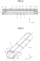
- FIG. 3 is a cross-sectional view illustrating a part of the linear motion guide device 1 according to the embodiment.
- the linear motion guide device 1 includes a guide rail 2, a slider 3, and rolling elements 4.
- the slider 3 is guided in the X-axis direction by the guide rail 2.
- the rolling elements 4 can roll in circulation passages 100.
- a circulation passage 100 includes a rolling passage 5, a return passage 6, and a direction changing passage 7.
- the rolling passage 5 is defined between the guide rail 2 and the slider 3.
- the return passage 6 is provided inside the slider 3.
- the direction changing passage 7 connects the rolling passage 5 with the return passage 6.
- the guide rail 2 guides the slider 3 in the X-axis direction.
- the guide rail 2 extends in the X-axis direction.
- the guide rail 2 has rolling grooves 8 extending in the X-axis direction. At least a part of a rolling element 4 is disposed inside a rolling groove 8.
- the inner surface of the rolling groove 8 has a rolling surface 9 that supports the rolling element 4.
- the rolling element 4 rolls in contact with the rolling surface 9.
- Three rolling grooves 8 are provided on a +Y side surface of the guide rail 2, and three rolling grooves 8 are provided on a -Y side surface of the guide rail 2.
- the three rolling grooves 8 are disposed in the Z-axis direction on the +Y side surface of the guide rail 2.
- the three rolling grooves 8 are disposed in the Z-axis direction on the -Y side surface of the guide rail 2.
- the slider 3 moves relative to the guide rail 2 in the X-axis direction while being guided by the guide rail 2. At least a part of the slider 3 faces the guide rail 2 via the rolling element 4.
- the slider 3 includes a slider main body 31, an end cap 33, and a return guide 32.
- the slider main body 31 extends in the X-axis direction.
- the end cap 33 is connected to an end of the slider main body 31 in the X-axis direction.
- the return guide 32 is disposed between the slider main body 31 and the end cap 33 so as to face the end cap 33.
- the slider main body 31 is made of metal.
- Each of the return guide 32 and the end cap 33 is made of synthetic resin. Note that one or both of the return guide 32 and the end cap 33 may be made of metal.
- one or both of the return guide 32 and the end cap 33 may be made of iron, steel, stainless steel, or aluminum.
- the slider main body 31 is disposed so as to straddle the guide rail 2.
- the slider main body 31 includes legs 31F and a body 31B.
- One leg 31F is disposed on the +Y side of the guide rail 2, and the other leg 31F is disposed on the -Y side of the guide rail 2.
- the body 31B is disposed on a +Z side of the guide rail 2, and connects the pair of legs 31F.
- the slider main body 31 has rolling grooves 10 extending in the X-axis direction.
- the rolling grooves 10 of the slider main body 31 face the rolling grooves 8 of the guide rail 2.
- the rolling grooves 10 are formed on the inner surfaces of the legs 31F facing the guide rail 2.
- At least a part of the rolling element 4 is disposed inside a rolling groove 10.
- the inner surface of the rolling groove 10 has a rolling surface 11 that supports the rolling element 4.
- the rolling element 4 rolls in contact with the rolling surface 11.
- Three rolling grooves 10 are provided on the inner surface of the leg 31F disposed on the +Y side of the guide rail 2, and three rolling grooves 10 are provided on the inner surface of the leg 31F disposed on the -Y side of the guide rail 2.
- Three rolling grooves 10 are disposed in the Z-axis direction on the inner surface of the leg 31F disposed on the +Y side of the guide rail 2.
- Three rolling grooves 10 are disposed in the Z-axis direction on the inner surface of the leg 31F disposed on the -Y side of the guide rail 2.
- the rolling element 4 is a ball made of metal. A plurality of rolling elements 4 is provided. The rolling elements 4 can roll and pass through the circulation passage 100 including the rolling passage 5, the return passage 6, and the direction changing passage 7.
- the rolling passage 5 is defined between the rolling surface 9 and the rolling surface 11.
- the rolling passage 5 extends in the X-axis direction between the guide rail 2 and the slider 3.
- the rolling element 4 can move in the X-axis direction while rolling through the rolling passage 5.
- the rolling element 4 rolls through the rolling passage 5 under load.
- Three rolling passages 5 are provided between the guide rail 2 and the leg 31F disposed on the +Y side of the guide rail 2.
- Three rolling passages 5 are provided between the guide rail 2 and the leg 31F disposed on the -Y side of the guide rail 2.
- the rolling element 4 rolls through the rolling passage 5 while being in contact with each of the rolling surface 9 and the rolling surface 11.
- the return passage 6 is provided inside the slider main body 31.
- the return passage 6 extends in the X-axis direction inside the slider main body 31.
- the rolling element 4 can move in the X-axis direction while rolling through the return passage 6.
- the rolling element 4 rolls through the return passage 6 under no load.
- the return passage 6 is provided outside the rolling passage 5 with respect to the center of the slider 3 in the Y-axis direction.
- the return passage 6 is provided inside the leg 31F.
- One return passage 6 is provided for one rolling passage 5.
- six rolling passages 5 are provided.
- Six return passages 6 are also provided.
- the rolling passage 5 and the return passage 6 are substantially parallel to each other.
- a traveling direction of the rolling element 4 moving through the rolling passage 5 is opposite to a traveling direction of the rolling element 4 moving through the return passage 6.
- the rolling element 4 in the rolling passage 5 travels in a +X direction through the rolling passage 5
- the rolling element 4 in the return passage 6 travels in a -X direction through the return passage 6.
- the rolling element 4 in the return passage 6 travels in a +X direction through the return passage 6.
- the direction changing passage 7 causes the rolling element 4 to roll and pass from one of the rolling passage 5 and the return passage 6 to the other.
- the direction changing passage 7 is defined between the end cap 33 and the return guide 32.
- the end cap 33 is connected to each of a +X-side end and a -X-side end of the slider main body 31.
- the end cap 33 is fixed to the slider main body 31 by, for example, a bolt 33B.
- the return guide 32 is connected to each of the +X-side end and the -X-side end of the slider main body 31 so as to face the end cap 33.
- the direction changing passage 7 is provided so as to connect the +X-side end of the rolling passage 5 with the +X-side end of the return passage 6.
- the direction changing passage 7 is provided so as to connect the -X-side end of the rolling passage 5 with the -X-side end of the return passage 6.
- the direction changing passage 7 has an arc shape connecting the end of the rolling passage 5 with the end of the return passage 6.
- the rolling element 4 that has moved in the +X direction through the rolling passage 5 and entered the direction changing passage 7 from the +X-side end of the rolling passage 5 can enter the return passage 6 from the +X-side end of the return passage 6 after moving through the direction changing passage 7.
- the rolling element 4 that has entered the return passage 6 from the +X-side end of the return passage 6 moves in the -X direction through the return passage 6.
- the rolling element 4 that has moved in the +X direction through the return passage 6 and entered the direction changing passage 7 from the +X-side end of the return passage 6 can enter the rolling passage 5 from the +X-side end of the rolling passage 5 after moving through the direction changing passage 7.
- the rolling element 4 that has entered the rolling passage 5 from the +X-side end of the rolling passage 5 moves in the -X direction through the rolling passage 5.
- the rolling passage 5, the return passage 6, and the direction changing passage 7 form the circulation passage 100 of the rolling element 4.
- the rolling element 4 rolls so as to circulate through the circulation passage 100, so that the slider 3 can move relative to the guide rail 2 in each of the +X direction and the -X direction.
- FIG. 4 is a perspective view schematically illustrating the return passage 6 according to the embodiment.
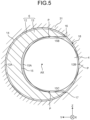
- FIG. 5 is a cross-sectional view illustrating the return passage 6 according to the embodiment.
- the return passage 6 includes a through hole 12 and a return guide member 13.
- the through hole 12 extends in the X-axis direction inside the slider 3.
- the return guide member 13 is disposed in the through hole 12.
- the through hole 12 is provided inside the slider main body 31.
- the through hole 12 extends in the X-axis direction inside the slider main body 31.
- a central axis AX of the through hole 12 is parallel to the X-axis.
- the central axis AX passes through the center of the through hole 12 in the YZ plane.
- the through hole 12 has a circular shape in the YZ plane orthogonal to the central axis AX.
- the through hole 12 has an inner peripheral surface disposed around the central axis AX.
- the slider main body 31 is made of metal.
- the through hole 12 is formed in the slider main body 31 by using a tool such as a drill.
- the return guide member 13 is disposed in the through hole 12.
- the return guide member 13 is made of synthetic resin. Note that the return guide member 13 may be made of rubber. An operator can elastically deform the return guide member 13 by manually applying force to the return guide member 13.
- the return guide member 13 has, in the YZ plane orthogonal to the central axis AX, an arc-shaped outer surface 14, an inner surface 15, a first end surface 16, and a second end surface 17.
- the outer surface 14 faces a part of the inner peripheral surface of the through hole 12. At least a part of the inner surface 15 is in contact with the rolling element 4.
- the first end surface 16 connects one end of the outer surface 14 with the inner surface 15 in a peripheral direction of the central axis AX.
- the second end surface 17 connects the other end of the outer surface 14 with the inner surface 15 in the peripheral direction of the central axis AX, and is separated from the first end surface 16. That is, in the embodiment, the return guide member 13 has an alphabet "C" shape in the YZ plane.
- An opening 18 is provided between the first end surface 16 and the second end surface 17.
- the return guide member 13 has a cross section, parallel to the YZ plane, having a size and a shape uniform in the X-axis direction.
- the outer surface 14 of the return guide member 13 is in contact with a part of the inner peripheral surface of the through hole 12 in the YZ plane.
- a region, facing the outer surface 14 of the return guide member 13, of the inner peripheral surface of the through hole 12 is appropriately referred to as a support region 12A.
- a region of the inner peripheral surface of the through hole 12 between the first end surface 16 and the second end surface 17 is appropriately referred to as an exposed region 12B.
- the support region 12A is defined in at least half of the inner peripheral surface of the through hole 12 in the peripheral direction of the central axis AX.
- the support region 12A occupies a region of 51 [%] or more and 99[%] or less of the inner peripheral surface of the through hole 12 in the peripheral direction of the central axis AX. In the example of FIG. 5 , the support region 12A occupies a region of approximately 70[%] of the inner peripheral surface of the through hole 12 in the peripheral direction of the central axis AX.
- the exposed region 12B is different from the region occupied by the support region 12A on the inner peripheral surface of the through hole 12.
- the exposed region 12B is disposed inside the opening 18.
- the rolling element 4 is in contact with at least a part of the exposed region 12B between the first end surface 16 and the second end surface 17.
- the outer surface 14 of the return guide member 13 is in contact with the support region 12A.
- the return guide member 13 is not contact with the exposed region 12B.
- the opening 18 between the first end surface 16 and the second end surface 17 is disposed outside the central axis AX with respect to the center of the slider 3 in the Y-axis direction. That is, the return guide member 13 is disposed in the through hole 12 such that the opening 18 faces outward with respect to the central axis AX.
- the support region 12A is defined at a position closer to the center of the slider 3 than the opening 18 and the exposed region 12B in the Y-axis direction.
- the inner surface 15 of the return guide member 13 has, in the YZ plane, an arcuate region 15A, a first linear region 15B, and a second linear region 15C.
- the first linear region 15B is connected to one end of the arcuate region 15A in the peripheral direction of the central axis AX.
- the second linear region 15C is connected to the other end of the arcuate region 15A in the peripheral direction of the central axis AX.
- the first linear region 15B extends in a tangential direction of the outer surface of the rolling element 4 in the YZ plane.
- the second linear region 15C extends in a tangential direction of the outer surface of the rolling element 4 in the YZ plane.
- first linear region 15B and the second linear region 15C are substantially parallel to each other.
- the arcuate region 15A has a curvature smaller than that of the outer surface of the rolling element 4.
- the inner peripheral surface of the through hole 12 has a curvature smaller than that of the arcuate region 15A.
- the rolling element 4 is in contact with the inner surface 15 at a contact point P defined on a part of the inner surface 15 of the return guide member 13.
- the rolling element 4 is in contact with the inner peripheral surface of the through hole 12 at the contact point P defined on a part of the inner peripheral surface of the through hole 12.
- the contact point P between the rolling element 4 and the inner surface 15 of the return guide member 13 is defined at each of the boundary between the arcuate region 15A and the first linear region 15B and the boundary between the arcuate region 15A and the second linear region 15C. That is, the rolling element 4 rolls while being in contact with each of the boundary between the arcuate region 15A and the first linear region 15B and the boundary between the arcuate region 15A and the second linear region 15C. In the embodiment, the rolling element 4 is not in contact with the arcuate region 15A.
- the contact point P between the rolling element 4 and the inner peripheral surface of the through hole 12 is defined in the exposed region 12B.
- the rolling element 4 when being in contact with the boundary between the arcuate region 15A and the first linear region 15B, the rolling element 4 may be separated from the boundary between the arcuate region 15A and the second linear region 15C. Note that, when being in contact with the boundary between the arcuate region 15A and the second linear region 15C, the rolling element 4 may be separated from the boundary between the arcuate region 15A and the first linear region 15B. Note that the rolling element 4 may be in contact with a part of the arcuate region 15A.
- a gap may be provided between the rolling element 4 and the inner surface 15 of the return guide member 13 and between the rolling element 4 and the inner peripheral surface of the through hole 12. That is, although, in the example of FIG. 5 , three contact points P are provided around the rolling element 4, one contact point P may be provided. Furthermore, a slight gap may be provided between the rolling element 4 and the return passage 6. The rolling element 4 may roll through the return passage 6 in a state of being in contact with neither the boundary between the arcuate region 15A and the first linear region 15B nor the boundary between the arcuate region 15A and the second linear region 15C.
- the distance between the contact point P defined at the boundary between the arcuate region 15A and the first linear region 15B and the contact point P defined at the boundary between the arcuate region 15A and the second linear region 15C is the same as or slightly larger than the diameter of the rolling element 4.
- the rolling element 4 can roll inside the return guide member 13 under no load.
- the through hole 12 is formed in the slider main body 31 by a tool such as a drill.
- the return guide member 13 is manufactured by, for example, injection molding. The operator inserts the return guide member 13 into the through hole 12.
- the return guide member 13 has the first end surface 16 and the second end surface 17. The operator can elastically deform the return guide member 13 so that the first end surface 16 and the second end surface 17 approach each other to decrease the outer diameter of the return guide member 13 by manually applying force to the return guide member 13. The operator can smoothly insert the return guide member 13 into the through hole 12 with the return guide member 13 being elastically deformed.
- the operator After the return guide member 13 is inserted into the through hole 12, the operator connects the return guide 32 and the end cap 33 to an end of the slider main body 31 in the X-axis direction. This causes the direction changing passage 7 to be formed in the slider 3.
- the return guide member 13 can be elastically deformed so as to have a smaller outer diameter by forming the return guide member 13 such that the return guide member 13 has the first end surface 16 and the second end surface 17 separated from the first end surface 16. This enables the operator to insert the return guide member 13 into the through hole 12 while elastically deforming the return guide member 13 even if the through hole 12 has a small inner diameter. This inhibits deterioration of workability in a case where the return guide member 13 is disposed in the through hole 12. Furthermore, since the inner diameter of the through hole 12 can be reduced, an increase in size of the linear motion guide device 1 is inhibited also in a case where a plurality of return passages 6 is provided so as to be adjacent to each other in the YZ plane.
- the inner surface 15 of the return guide member 13 has, in the YZ plane, an arcuate region 15A, a first linear region 15B, and a second linear region 15C.
- the first linear region 15B is connected to one end of the arcuate region 15A in the peripheral direction of the central axis AX, and extends in the tangential direction of the rolling element 4.
- the second linear region 15C is connected to the other end of the arcuate region 15A, and extends in the tangential direction of the rolling element 4.
- the arcuate region 15A has a curvature smaller than that of the rolling element 4. This inhibits excessively close contact of the inner surface 15 of the return guide member 13 with the rolling element 4. Therefore, the rolling element 4 can smoothly roll inside the return guide member 13.
- the contact point P between the rolling element 4 and the inner surface 15 of the return guide member 13 is defined at at least one of the boundary between the arcuate region 15A and the first linear region 15B and the boundary between the arcuate region 15A and the second linear region 15C. This enables the rolling element 4 to smoothly roll inside the return guide member 13 while being supported by a part of the inner surface 15 of the return guide member 13.
- the first linear region 15B and the second linear region 15C are parallel to each other. This inhibits contact of the first linear region 15B and the second linear region 15C with the rolling element 4 even in a case where the return guide member 13 is elastically deformed so that the first end surface 16 and the second end surface 17 approach each other when the return guide member 13 is disposed in the through hole 12. Excessively close contact of the inner surface 15 of the return guide member 13 with the rolling element 4 can thus be inhibited. Therefore, the rolling element 4 can smoothly roll inside the return guide member 13. Furthermore, when the return guide member 13 is formed by injection molding, the return guide member 13 can be smoothly removed from a mold by providing the first linear region 15B and the second linear region 15C in parallel to each other.
- the rolling element 4 is in contact with the exposed region 12B of the through hole 12 between the first end surface 16 and the second end surface 17. This enables the rolling element 4 to smoothly roll through the return passage 6 while being supported by each of the inner surface 15 of the return guide member 13 and the inner peripheral surface of the through hole 12.
- the outer surface 14 of the return guide member 13 faces the support region 12A defined in at least half of the inner peripheral surface of the through hole 12 in the peripheral direction of the central axis AX. This causes the outer surface 14 of the return guide member 13 to be supported by the support region 12A of half or more of the inner peripheral surface of the through hole 12. Movement of the return guide member 13 inside the through hole 12 is thus inhibited after the return guide member 13 is disposed in the through hole 12. Thus, the rolling element 4 can smoothly roll inside the return guide member 13.
- the return passage 6 is provided outside the rolling passage 5 with respect to the center of the slider 3 in the Y-axis direction.
- the opening 18 between the first end surface 16 and the second end surface 17 is disposed outside the central axis AX in the Y-axis direction. This inhibits a decrease in the turning radius at the time when the rolling element 4 rolls in the direction changing passage 7 between the return passage 6 and the rolling passage 5. Therefore, the rolling element 4 can smoothly roll through the direction changing passage 7.
- FIG. 6 is a cross-sectional view illustrating the return passage 6 according to the embodiment.
- the first linear region 15B and the second linear region 15C may be inclined such that the distance between the first linear region 15B and the second linear region 15C decreases outward from the center of the slider 3 in the Y-axis direction.
- the contact point P between the rolling element 4 and the inner surface 15 of the return guide member 13 is defined at each of the boundary between the arcuate region 15A and the first linear region 15B and the boundary between the arcuate region 15A and the second linear region 15C.
- FIG. 7 is a cross-sectional view illustrating the return passage 6 according to the embodiment.
- the first linear region 15B and the second linear region 15C may be inclined such that the distance between the first linear region 15B and the second linear region 15C increases outward from the center of the slider 3 in the Y-axis direction.
- the contact point P between the rolling element 4 and the inner surface 15 of the return guide member 13 is defined at each of the boundary between the arcuate region 15A and the first linear region 15B and the boundary between the arcuate region 15A and the second linear region 15C.
- FIG. 8 is a perspective view schematically illustrating the return passage 6 according to the embodiment.
- the return guide member 13 may include a first return guide member 131 and a second return guide member 132 connected to an end of the first return guide member 131 in the X-axis direction. That is, the return guide member 13 may be formed by combining a plurality of members.
- the return guide member 13 can be smoothly disposed in the through hole 12 by inserting the first return guide member 131 from one end of the through hole 12 and inserting the second return guide member 132 from the other end of the through hole 12.
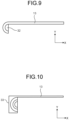
- FIG. 9 is a plan view schematically illustrating the return passage 6 according to the embodiment.
- the return guide member 13 may be integrated with the return guide 32.
- the return guide member 13 and the return guide 32 may be formed by injection molding such that the return guide member 13 and the return guide 32 are integrally molded by using a single mold. According to the embodiment, the number of components of the linear motion guide device 1 can be reduced.
- FIG. 10 is a plan view schematically illustrating the return passage 6 according to the embodiment.
- the return guide member 13 may be integrated with the end cap 33.
- the return guide member 13 and the end cap 33 may be formed by injection molding such that the return guide member 13 and the end cap 33 are integrally molded by using a single mold. Also in the embodiment, the number of components of the linear motion guide device 1 can be reduced.
- the return guide member 13 is disposed in the through hole 12 such that the opening 18 between the first end surface 16 and the second end surface 17 faces outward with respect to the center of the slider 3.
- the return guide member 13 may be disposed in the through hole 12 such that the opening 18 faces the center of the slider 3.
- the return guide member 13 may be disposed in the through hole 12 such that the opening 18 faces the +Z direction.
- the return guide member 13 may be disposed in the through hole 12 such that the opening 18 faces the -Z direction.
- the opening 18 is formed between the first end surface 16 and the second end surface 17 with the return guide member 13 being disposed in the through hole 12.
- the first end surface 16 and the second end surface 17 may be in contact with each other with the return guide member 13 being disposed in the through hole 12. That is, the support region 12A may occupy a region of approximately 100[%] of the inner peripheral surface of the through hole 12 in the peripheral direction of the central axis AX.
Landscapes
- Engineering & Computer Science (AREA)
- General Engineering & Computer Science (AREA)
- Mechanical Engineering (AREA)
- Bearings For Parts Moving Linearly (AREA)
Abstract
Description
- The present disclosure relates to a linear motion guide device provided in a guide unit of a machine tool, a manufacturing device, a measuring instrument, or the like and configured to linearly move a moving member such as a table.
- A linear motion guide device includes: a guide rail; a slider; and a large number of balls. The guide rail extends in an axial direction, and has ball rolling grooves on both side surfaces. The slider is disposed so as to straddle the guide rail. The slider includes a ball rolling groove, both ends of a ball return passage, and a direction changing passage for the balls. The ball rolling groove is located at a position facing the ball rolling groove of the guide rail. The ball return passage is formed in parallel to the ball rolling passage. The direction changing passage connects the ball rolling passage with both ends of the ball return passage. The balls are arranged in a ball circulation passage including the ball rolling groove of the guide rail, the ball rolling groove of the slider, the ball rolling passage, and the direction changing passage.
- The slider includes a slider main body and an end cap. In the slider main body, the ball rolling groove and a ball return passage are formed. In the end cap, a direction changing passage is formed. The end cap is fixed to both end surfaces in the axial direction of the slider main body. In a technical field related to linear motion guide devices, a linear motion guide device including a slider main body having a return passage for a rolling element as disclosed in
Patent Literature 1 is known. InPatent Literature 1, the return passage includes a through hole and a return guide member. The through hole is provided inside the slider main body. The return guide member is disposed in the through hole. Even in a case where the through hole has a large inner diameter, the return guide member disposed in the through hole enables a rolling element having a small diameter to roll in the return passage. Since it is unnecessary to reduce the inner diameter of the through hole, deterioration of workability in a case where a through hole is formed is inhibited. - Patent Literature 1:
JP 2008-175263 A - A return guide member disposed in a through hole eliminates the need for reducing the inner diameter of the through hole. When a decrease in size of a linear motion guide device is required, however, the inner diameter of the through hole is preferably small. There is a demand for a technique capable of smoothly putting a return guide member in a through hole even in a case where the through hole has a small inner diameter.
- An object of the present disclosure is to provide a linear motion guide device that inhibits deterioration of workability in a case where a return guide member is disposed in a through hole and inhibits an increase in size.
- A linear motion guide device according to an embodiment of the present disclosure comprising: a guide rail; a slider that is guided by the guide rail in a first axis direction; and a rolling element allowed to roll in a circulation passage including: a rolling passage defined between the guide rail and the slider; a return passage provided inside the slider; and a direction changing passage connecting the rolling passage with the return passage, wherein the return passage includes: a through hole extending in the first axis direction inside the slider; and a return guide member disposed in the through hole, and the return guide member has, in a predetermined plane orthogonal to a central axis of the through hole: an outer surface having an arc shape facing a part of an inner peripheral surface of the through hole; an inner surface at least a part of which is in contact with the rolling element; a first end surface connecting one end of the outer surface with the inner surface in a peripheral direction of the central axis; and a second end surface connecting another end of the outer surface with the inner surface and separated from the first end surface.
- According to this, a return guide member can be elastically deformed so as to have a smaller outer diameter by forming the return guide member such that the return guide member has a first end surface and a second end surface separated from the first end surface. This enables the return guide member to be inserted into a through hole while being elastically deformed even if the through hole has a small inner diameter. This inhibits deterioration of workability in a case where the return guide member is disposed in the through hole. Furthermore, since the inner diameter of the through hole can be reduced, an increase in size of the linear motion guide device is inhibited also in a case where a plurality of return passages is provided so as to be adjacent to each other in a predetermined plane, for example.
- As a desirable embodiment of the linear motion guide device according to the present disclosure, the inner surface may have, in the predetermined plane: an arcuate region; a first linear region connected to one end of the arcuate region in a peripheral direction of the central axis and extending in a tangential direction of the rolling element; and a second linear region connected to another end of the arcuate region and extending in a tangential direction of the rolling element.
- According to this, excessively close contact of the inner surface of the return guide member with the rolling element is inhibited even in a case where the return guide member is elastically deformed so that the first end surface and the second end surface approach each other when the return guide member is disposed in the through hole. Therefore, the rolling element can smoothly roll inside the return guide member. Furthermore, when the return guide member is formed by a mold, the return guide member can be smoothly removed from the mold by providing a first linear region and a second linear region.
- As a desirable embodiment of the linear motion guide device according to the present disclosure, the arcuate region may have a curvature smaller than a curvature of the rolling element in the predetermined plane.
- According to this, excessively close contact of the inner surface of the return guide member with the rolling element is inhibited. Therefore, the rolling element can smoothly roll inside the return guide member.
- As a desirable embodiment of the linear motion guide device according to the present disclosure, a contact point between the rolling element and the inner surface may be defined at at least one of a boundary between the arcuate region and the first linear region and a boundary between the arcuate region and the second linear region.
- According to this, the rolling element can smoothly roll inside the return guide member while being supported by a part of the inner surface of the return guide member.
- As a desirable embodiment of the linear motion guide device according to the present disclosure, the first linear region and the second linear region may be parallel to each other in the predetermined plane.
- According to this, excessively close contact of the inner surface of the return guide member with the rolling element is inhibited even in a case where the return guide member is elastically deformed so that the first end surface and the second end surface approach each other when the return guide member is disposed in the through hole. Therefore, the rolling element can smoothly roll inside the return guide member. Furthermore, when the return guide member is formed by a mold, the return guide member can be smoothly removed from the mold by providing the first linear region and the second linear region in parallel to each other.
- As a desirable embodiment of the linear motion guide device according to the present disclosure, the rolling element may be in contact with the inner peripheral surface between the first end surface and the second end surface.
- According to this, the rolling element can smoothly roll through the return passage while being supported by each of the inner surface of the return guide member and the inner peripheral surface of the through hole.
- As a desirable embodiment of the linear motion guide device according to the present disclosure, the outer surface may face a support region defined in at least half of the inner peripheral surface in a peripheral direction of the central axis.
- According to this, the outer surface of the return guide member is supported by the support region of half or more of the inner peripheral surface of the through hole. Movement of the return guide member inside the through hole is thus inhibited after the return guide member is disposed in the through hole. Thus, the rolling element can smoothly roll inside the return guide member.
- As a desirable embodiment of the linear motion guide device according to the present disclosure, the return passage may be provided outside the rolling passage with respect to a center of the slider in a second axis direction of the predetermined plane orthogonal to the first axis direction, and an opening between the first end surface and the second end surface may be disposed outside the central axis in the second axis direction.
- According to this, a decrease in the turning radius at the time when the rolling element rolls in the direction changing passage between the return passage and the rolling passage is inhibited. Therefore, the rolling element can smoothly roll through the direction changing passage.
- As a desirable embodiment of the linear motion guide device according to the present disclosure, the return guide member may include: a first return guide member; and a second return guide member connected to one end of the first return guide member in the first axis direction.
- According to this, even in a case where the through hole has a large dimension in a first axis direction, the return guide member can be smoothly disposed in the through hole by inserting a first return guide member from one end of the through hole and inserting a second return guide member from the other end of the through hole.
- As a desirable embodiment of the linear motion guide device according to the present disclosure, the slider may include: a slider main body provided with the through hole; an end cap connected to an end of the slider main body in the first axis direction; and a return guide disposed between the slider main body and the end cap so as to face the end cap, the direction changing passage may be defined between the end cap and the return guide, and the return guide member may be integrated with at least one of the return guide and the end cap.
- According to this, the return guide member is integrated with at least one of a return guide and an end cap, so that the number of components of the linear motion guide device is reduced.
- According to the present disclosure, there is provided a linear motion guide device that inhibits deterioration of workability in a case where a return guide member is disposed in a through hole and inhibits an increase in size.
-
-
FIG. 1 is a perspective view illustrating a linear motion guide device according to a first embodiment. -
FIG. 2 is a front view in which a part of the linear motion guide device according to the first embodiment is broken. -
FIG. 3 is a cross-sectional view illustrating a part of the linear motion guide device according to the first embodiment. -
FIG. 4 is a perspective view schematically illustrating a return passage according to the first embodiment. -
FIG. 5 is a cross-sectional view illustrating the return passage according to the first embodiment. -
FIG. 6 is a cross-sectional view illustrating the return passage according to the second embodiment. -
FIG. 7 is a cross-sectional view illustrating the return passage according to a third embodiment. -
FIG. 8 is a perspective view schematically illustrating the return passage according to a fourth embodiment. -
FIG. 9 is a plan view schematically illustrating the return passage according to a fifth embodiment. -
FIG. 10 is a plan view schematically illustrating the return passage according to a sixth embodiment. Description of Embodiments - Although embodiments according to the present disclosure will be described below with reference to the drawings, the present disclosure is not limited thereto. Components of the embodiments to be described below can be appropriately combined. Furthermore, some components are not used in some cases.
- In the embodiments, an XYZ orthogonal coordinate system is set, and the positional relation between respective parts will be described with reference to the XYZ orthogonal coordinate system. A direction parallel to an X-axis (first axis) in a horizontal plane is defined as an X-axis direction (first axis direction). A direction parallel to a Y-axis (second axis) in the horizontal plane orthogonal to the X-axis is defined as a Y-axis direction (second axis direction). A direction parallel to a Z-axis (third axis) orthogonal to the horizontal plane is defined as a Z-axis direction (third direction). A YZ plane is a predetermined plane including the Y-axis and the Z-axis, and is orthogonal to the X-axis.
- A first embodiment will be described.
FIG. 1 is a perspective view illustrating a linearmotion guide device 1 according to the embodiment.FIG. 2 is a front view in which a part of the linearmotion guide device 1 according to the embodiment is broken.FIG. 3 is a cross-sectional view illustrating a part of the linearmotion guide device 1 according to the embodiment. - As illustrated in
FIGS. 1 and2 , the linearmotion guide device 1 includes aguide rail 2, aslider 3, and rollingelements 4. Theslider 3 is guided in the X-axis direction by theguide rail 2. The rollingelements 4 can roll incirculation passages 100. Acirculation passage 100 includes a rollingpassage 5, areturn passage 6, and adirection changing passage 7. The rollingpassage 5 is defined between theguide rail 2 and theslider 3. Thereturn passage 6 is provided inside theslider 3. Thedirection changing passage 7 connects the rollingpassage 5 with thereturn passage 6. - The
guide rail 2 guides theslider 3 in the X-axis direction. Theguide rail 2 extends in the X-axis direction. Theguide rail 2 has rollinggrooves 8 extending in the X-axis direction. At least a part of a rollingelement 4 is disposed inside a rollinggroove 8. The inner surface of the rollinggroove 8 has a rollingsurface 9 that supports the rollingelement 4. The rollingelement 4 rolls in contact with the rollingsurface 9. - Three rolling
grooves 8 are provided on a +Y side surface of theguide rail 2, and three rollinggrooves 8 are provided on a -Y side surface of theguide rail 2. The threerolling grooves 8 are disposed in the Z-axis direction on the +Y side surface of theguide rail 2. The threerolling grooves 8 are disposed in the Z-axis direction on the -Y side surface of theguide rail 2. - The
slider 3 moves relative to theguide rail 2 in the X-axis direction while being guided by theguide rail 2. At least a part of theslider 3 faces theguide rail 2 via the rollingelement 4. - The
slider 3 includes a slidermain body 31, anend cap 33, and areturn guide 32. The slidermain body 31 extends in the X-axis direction. Theend cap 33 is connected to an end of the slidermain body 31 in the X-axis direction. The return guide 32 is disposed between the slidermain body 31 and theend cap 33 so as to face theend cap 33. The slidermain body 31 is made of metal. Each of thereturn guide 32 and theend cap 33 is made of synthetic resin. Note that one or both of thereturn guide 32 and theend cap 33 may be made of metal. For example, one or both of thereturn guide 32 and theend cap 33 may be made of iron, steel, stainless steel, or aluminum. - The slider
main body 31 is disposed so as to straddle theguide rail 2. The slidermain body 31 includeslegs 31F and abody 31B. Oneleg 31F is disposed on the +Y side of theguide rail 2, and theother leg 31F is disposed on the -Y side of theguide rail 2. Thebody 31B is disposed on a +Z side of theguide rail 2, and connects the pair oflegs 31F. - The slider
main body 31 has rollinggrooves 10 extending in the X-axis direction. The rollinggrooves 10 of the slidermain body 31 face the rollinggrooves 8 of theguide rail 2. The rollinggrooves 10 are formed on the inner surfaces of thelegs 31F facing theguide rail 2. At least a part of the rollingelement 4 is disposed inside a rollinggroove 10. The inner surface of the rollinggroove 10 has a rollingsurface 11 that supports the rollingelement 4. The rollingelement 4 rolls in contact with the rollingsurface 11. - Three rolling
grooves 10 are provided on the inner surface of theleg 31F disposed on the +Y side of theguide rail 2, and three rollinggrooves 10 are provided on the inner surface of theleg 31F disposed on the -Y side of theguide rail 2. Three rollinggrooves 10 are disposed in the Z-axis direction on the inner surface of theleg 31F disposed on the +Y side of theguide rail 2. Three rollinggrooves 10 are disposed in the Z-axis direction on the inner surface of theleg 31F disposed on the -Y side of theguide rail 2. - The rolling
element 4 is a ball made of metal. A plurality of rollingelements 4 is provided. The rollingelements 4 can roll and pass through thecirculation passage 100 including the rollingpassage 5, thereturn passage 6, and thedirection changing passage 7. - The rolling
passage 5 is defined between the rollingsurface 9 and the rollingsurface 11. The rollingpassage 5 extends in the X-axis direction between theguide rail 2 and theslider 3. The rollingelement 4 can move in the X-axis direction while rolling through the rollingpassage 5. The rollingelement 4 rolls through the rollingpassage 5 under load. Three rollingpassages 5 are provided between theguide rail 2 and theleg 31F disposed on the +Y side of theguide rail 2. Three rollingpassages 5 are provided between theguide rail 2 and theleg 31F disposed on the -Y side of theguide rail 2. The rollingelement 4 rolls through the rollingpassage 5 while being in contact with each of the rollingsurface 9 and the rollingsurface 11. - The
return passage 6 is provided inside the slidermain body 31. Thereturn passage 6 extends in the X-axis direction inside the slidermain body 31. The rollingelement 4 can move in the X-axis direction while rolling through thereturn passage 6. The rollingelement 4 rolls through thereturn passage 6 under no load. Thereturn passage 6 is provided outside the rollingpassage 5 with respect to the center of theslider 3 in the Y-axis direction. In the embodiment, thereturn passage 6 is provided inside theleg 31F. Onereturn passage 6 is provided for one rollingpassage 5. In the embodiment, six rollingpassages 5 are provided. Sixreturn passages 6 are also provided. The rollingpassage 5 and thereturn passage 6 are substantially parallel to each other. - A traveling direction of the rolling
element 4 moving through the rollingpassage 5 is opposite to a traveling direction of the rollingelement 4 moving through thereturn passage 6. When the rollingelement 4 in the rollingpassage 5 travels in a +X direction through the rollingpassage 5, the rollingelement 4 in thereturn passage 6 travels in a -X direction through thereturn passage 6. When the rollingelement 4 in the rollingpassage 5 travels in a -X direction through the rollingpassage 5, the rollingelement 4 in thereturn passage 6 travels in a +X direction through thereturn passage 6. - The
direction changing passage 7 causes the rollingelement 4 to roll and pass from one of the rollingpassage 5 and thereturn passage 6 to the other. Thedirection changing passage 7 is defined between theend cap 33 and thereturn guide 32. - The
end cap 33 is connected to each of a +X-side end and a -X-side end of the slidermain body 31. Theend cap 33 is fixed to the slidermain body 31 by, for example, abolt 33B. The return guide 32 is connected to each of the +X-side end and the -X-side end of the slidermain body 31 so as to face theend cap 33. - The
direction changing passage 7 is provided so as to connect the +X-side end of the rollingpassage 5 with the +X-side end of thereturn passage 6. Thedirection changing passage 7 is provided so as to connect the -X-side end of the rollingpassage 5 with the -X-side end of thereturn passage 6. Thedirection changing passage 7 has an arc shape connecting the end of the rollingpassage 5 with the end of thereturn passage 6. - For example, the rolling
element 4 that has moved in the +X direction through the rollingpassage 5 and entered thedirection changing passage 7 from the +X-side end of the rollingpassage 5 can enter thereturn passage 6 from the +X-side end of thereturn passage 6 after moving through thedirection changing passage 7. The rollingelement 4 that has entered thereturn passage 6 from the +X-side end of thereturn passage 6 moves in the -X direction through thereturn passage 6. The rollingelement 4 that has moved in the +X direction through thereturn passage 6 and entered thedirection changing passage 7 from the +X-side end of thereturn passage 6 can enter the rollingpassage 5 from the +X-side end of the rollingpassage 5 after moving through thedirection changing passage 7. The rollingelement 4 that has entered the rollingpassage 5 from the +X-side end of the rollingpassage 5 moves in the -X direction through the rollingpassage 5. - The rolling
passage 5, thereturn passage 6, and thedirection changing passage 7 form thecirculation passage 100 of the rollingelement 4. The rollingelement 4 rolls so as to circulate through thecirculation passage 100, so that theslider 3 can move relative to theguide rail 2 in each of the +X direction and the -X direction. - Next, the
return passage 6 according to the embodiment will be described.FIG. 4 is a perspective view schematically illustrating thereturn passage 6 according to the embodiment.FIG. 5 is a cross-sectional view illustrating thereturn passage 6 according to the embodiment. - As illustrated in
FIGS. 2 ,3 ,4 , and5 , in the embodiment, thereturn passage 6 includes a throughhole 12 and areturn guide member 13. The throughhole 12 extends in the X-axis direction inside theslider 3. Thereturn guide member 13 is disposed in the throughhole 12. - The through
hole 12 is provided inside the slidermain body 31. The throughhole 12 extends in the X-axis direction inside the slidermain body 31. A central axis AX of the throughhole 12 is parallel to the X-axis. The central axis AX passes through the center of the throughhole 12 in the YZ plane. The throughhole 12 has a circular shape in the YZ plane orthogonal to the central axis AX. The throughhole 12 has an inner peripheral surface disposed around the central axis AX. - As described above, the slider
main body 31 is made of metal. The throughhole 12 is formed in the slidermain body 31 by using a tool such as a drill. - The
return guide member 13 is disposed in the throughhole 12. Thereturn guide member 13 is made of synthetic resin. Note that thereturn guide member 13 may be made of rubber. An operator can elastically deform thereturn guide member 13 by manually applying force to thereturn guide member 13. - As illustrated in
FIG. 5 , thereturn guide member 13 has, in the YZ plane orthogonal to the central axis AX, an arc-shapedouter surface 14, aninner surface 15, afirst end surface 16, and asecond end surface 17. Theouter surface 14 faces a part of the inner peripheral surface of the throughhole 12. At least a part of theinner surface 15 is in contact with the rollingelement 4. Thefirst end surface 16 connects one end of theouter surface 14 with theinner surface 15 in a peripheral direction of the central axis AX. Thesecond end surface 17 connects the other end of theouter surface 14 with theinner surface 15 in the peripheral direction of the central axis AX, and is separated from thefirst end surface 16. That is, in the embodiment, thereturn guide member 13 has an alphabet "C" shape in the YZ plane. Anopening 18 is provided between thefirst end surface 16 and thesecond end surface 17. - The
return guide member 13 has a cross section, parallel to the YZ plane, having a size and a shape uniform in the X-axis direction. - The
outer surface 14 of thereturn guide member 13 is in contact with a part of the inner peripheral surface of the throughhole 12 in the YZ plane. In the following description, a region, facing theouter surface 14 of thereturn guide member 13, of the inner peripheral surface of the throughhole 12 is appropriately referred to as asupport region 12A. Furthermore, in the following description, a region of the inner peripheral surface of the throughhole 12 between thefirst end surface 16 and thesecond end surface 17 is appropriately referred to as an exposedregion 12B. - The
support region 12A is defined in at least half of the inner peripheral surface of the throughhole 12 in the peripheral direction of the central axis AX. Thesupport region 12A occupies a region of 51 [%] or more and 99[%] or less of the inner peripheral surface of the throughhole 12 in the peripheral direction of the central axis AX. In the example ofFIG. 5 , thesupport region 12A occupies a region of approximately 70[%] of the inner peripheral surface of the throughhole 12 in the peripheral direction of the central axis AX. - The exposed
region 12B is different from the region occupied by thesupport region 12A on the inner peripheral surface of the throughhole 12. The exposedregion 12B is disposed inside theopening 18. The rollingelement 4 is in contact with at least a part of the exposedregion 12B between thefirst end surface 16 and thesecond end surface 17. - The
outer surface 14 of thereturn guide member 13 is in contact with thesupport region 12A. Thereturn guide member 13 is not contact with the exposedregion 12B. - The
opening 18 between thefirst end surface 16 and thesecond end surface 17 is disposed outside the central axis AX with respect to the center of theslider 3 in the Y-axis direction. That is, thereturn guide member 13 is disposed in the throughhole 12 such that theopening 18 faces outward with respect to the central axis AX. Thesupport region 12A is defined at a position closer to the center of theslider 3 than theopening 18 and the exposedregion 12B in the Y-axis direction. - The
inner surface 15 of thereturn guide member 13 has, in the YZ plane, anarcuate region 15A, a firstlinear region 15B, and a secondlinear region 15C. The firstlinear region 15B is connected to one end of thearcuate region 15A in the peripheral direction of the central axis AX. The secondlinear region 15C is connected to the other end of thearcuate region 15A in the peripheral direction of the central axis AX. - The first
linear region 15B extends in a tangential direction of the outer surface of the rollingelement 4 in the YZ plane. The secondlinear region 15C extends in a tangential direction of the outer surface of the rollingelement 4 in the YZ plane. - In the YZ plane, the first
linear region 15B and the secondlinear region 15C are substantially parallel to each other. - In the YZ plane, the
arcuate region 15A has a curvature smaller than that of the outer surface of the rollingelement 4. In the YZ plane, the inner peripheral surface of the throughhole 12 has a curvature smaller than that of thearcuate region 15A. - The rolling
element 4 is in contact with theinner surface 15 at a contact point P defined on a part of theinner surface 15 of thereturn guide member 13. The rollingelement 4 is in contact with the inner peripheral surface of the throughhole 12 at the contact point P defined on a part of the inner peripheral surface of the throughhole 12. In the embodiment, the contact point P between the rollingelement 4 and theinner surface 15 of thereturn guide member 13 is defined at each of the boundary between thearcuate region 15A and the firstlinear region 15B and the boundary between thearcuate region 15A and the secondlinear region 15C. That is, the rollingelement 4 rolls while being in contact with each of the boundary between thearcuate region 15A and the firstlinear region 15B and the boundary between thearcuate region 15A and the secondlinear region 15C. In the embodiment, the rollingelement 4 is not in contact with thearcuate region 15A. - The contact point P between the rolling
element 4 and the inner peripheral surface of the throughhole 12 is defined in the exposedregion 12B. - Note that, when being in contact with the boundary between the
arcuate region 15A and the firstlinear region 15B, the rollingelement 4 may be separated from the boundary between thearcuate region 15A and the secondlinear region 15C. Note that, when being in contact with the boundary between thearcuate region 15A and the secondlinear region 15C, the rollingelement 4 may be separated from the boundary between thearcuate region 15A and the firstlinear region 15B. Note that the rollingelement 4 may be in contact with a part of thearcuate region 15A. - Furthermore, a gap may be provided between the rolling
element 4 and theinner surface 15 of thereturn guide member 13 and between the rollingelement 4 and the inner peripheral surface of the throughhole 12. That is, although, in the example ofFIG. 5 , three contact points P are provided around the rollingelement 4, one contact point P may be provided. Furthermore, a slight gap may be provided between the rollingelement 4 and thereturn passage 6. The rollingelement 4 may roll through thereturn passage 6 in a state of being in contact with neither the boundary between thearcuate region 15A and the firstlinear region 15B nor the boundary between thearcuate region 15A and the secondlinear region 15C. - The distance between the contact point P defined at the boundary between the
arcuate region 15A and the firstlinear region 15B and the contact point P defined at the boundary between thearcuate region 15A and the secondlinear region 15C is the same as or slightly larger than the diameter of the rollingelement 4. The rollingelement 4 can roll inside thereturn guide member 13 under no load. - Next, a method of assembling the
slider 3 according to the embodiment will be described. The throughhole 12 is formed in the slidermain body 31 by a tool such as a drill. Thereturn guide member 13 is manufactured by, for example, injection molding. The operator inserts thereturn guide member 13 into the throughhole 12. Thereturn guide member 13 has thefirst end surface 16 and thesecond end surface 17. The operator can elastically deform thereturn guide member 13 so that thefirst end surface 16 and thesecond end surface 17 approach each other to decrease the outer diameter of thereturn guide member 13 by manually applying force to thereturn guide member 13. The operator can smoothly insert thereturn guide member 13 into the throughhole 12 with thereturn guide member 13 being elastically deformed. - After the
return guide member 13 is inserted into the throughhole 12, the operator connects thereturn guide 32 and theend cap 33 to an end of the slidermain body 31 in the X-axis direction. This causes thedirection changing passage 7 to be formed in theslider 3. - As described above, according to the embodiment, the
return guide member 13 can be elastically deformed so as to have a smaller outer diameter by forming thereturn guide member 13 such that thereturn guide member 13 has thefirst end surface 16 and thesecond end surface 17 separated from thefirst end surface 16. This enables the operator to insert thereturn guide member 13 into the throughhole 12 while elastically deforming thereturn guide member 13 even if the throughhole 12 has a small inner diameter. This inhibits deterioration of workability in a case where thereturn guide member 13 is disposed in the throughhole 12. Furthermore, since the inner diameter of the throughhole 12 can be reduced, an increase in size of the linearmotion guide device 1 is inhibited also in a case where a plurality ofreturn passages 6 is provided so as to be adjacent to each other in the YZ plane. - The
inner surface 15 of thereturn guide member 13 has, in the YZ plane, anarcuate region 15A, a firstlinear region 15B, and a secondlinear region 15C. The firstlinear region 15B is connected to one end of thearcuate region 15A in the peripheral direction of the central axis AX, and extends in the tangential direction of the rollingelement 4. The secondlinear region 15C is connected to the other end of thearcuate region 15A, and extends in the tangential direction of the rollingelement 4. This inhibits contact of the firstlinear region 15B and the secondlinear region 15C with the rollingelement 4 even in a case where thereturn guide member 13 is elastically deformed so that thefirst end surface 16 and thesecond end surface 17 approach each other when thereturn guide member 13 is disposed in the throughhole 12. Excessively close contact of theinner surface 15 of thereturn guide member 13 with the rollingelement 4 can thus be inhibited. Therefore, the rollingelement 4 can smoothly roll inside thereturn guide member 13. Furthermore, when thereturn guide member 13 is formed by injection molding, thereturn guide member 13 can be smoothly removed from a mold by providing the firstlinear region 15B and the secondlinear region 15C. - In the YZ plane, the
arcuate region 15A has a curvature smaller than that of the rollingelement 4. This inhibits excessively close contact of theinner surface 15 of thereturn guide member 13 with the rollingelement 4. Therefore, the rollingelement 4 can smoothly roll inside thereturn guide member 13. - The contact point P between the rolling
element 4 and theinner surface 15 of thereturn guide member 13 is defined at at least one of the boundary between thearcuate region 15A and the firstlinear region 15B and the boundary between thearcuate region 15A and the secondlinear region 15C. This enables the rollingelement 4 to smoothly roll inside thereturn guide member 13 while being supported by a part of theinner surface 15 of thereturn guide member 13. - In the YZ plane, the first
linear region 15B and the secondlinear region 15C are parallel to each other. This inhibits contact of the firstlinear region 15B and the secondlinear region 15C with the rollingelement 4 even in a case where thereturn guide member 13 is elastically deformed so that thefirst end surface 16 and thesecond end surface 17 approach each other when thereturn guide member 13 is disposed in the throughhole 12. Excessively close contact of theinner surface 15 of thereturn guide member 13 with the rollingelement 4 can thus be inhibited. Therefore, the rollingelement 4 can smoothly roll inside thereturn guide member 13. Furthermore, when thereturn guide member 13 is formed by injection molding, thereturn guide member 13 can be smoothly removed from a mold by providing the firstlinear region 15B and the secondlinear region 15C in parallel to each other. - The rolling
element 4 is in contact with the exposedregion 12B of the throughhole 12 between thefirst end surface 16 and thesecond end surface 17. This enables the rollingelement 4 to smoothly roll through thereturn passage 6 while being supported by each of theinner surface 15 of thereturn guide member 13 and the inner peripheral surface of the throughhole 12. - The
outer surface 14 of thereturn guide member 13 faces thesupport region 12A defined in at least half of the inner peripheral surface of the throughhole 12 in the peripheral direction of the central axis AX. This causes theouter surface 14 of thereturn guide member 13 to be supported by thesupport region 12A of half or more of the inner peripheral surface of the throughhole 12. Movement of thereturn guide member 13 inside the throughhole 12 is thus inhibited after thereturn guide member 13 is disposed in the throughhole 12. Thus, the rollingelement 4 can smoothly roll inside thereturn guide member 13. - The
return passage 6 is provided outside the rollingpassage 5 with respect to the center of theslider 3 in the Y-axis direction. Theopening 18 between thefirst end surface 16 and thesecond end surface 17 is disposed outside the central axis AX in the Y-axis direction. This inhibits a decrease in the turning radius at the time when the rollingelement 4 rolls in thedirection changing passage 7 between thereturn passage 6 and the rollingpassage 5. Therefore, the rollingelement 4 can smoothly roll through thedirection changing passage 7. - A second embodiment will be described. In the following description, components same as or equivalent to those of the above-described embodiment are denoted by the same reference signs, and the description thereof will be simplified or omitted.
-
FIG. 6 is a cross-sectional view illustrating thereturn passage 6 according to the embodiment. As illustrated inFIG. 6 , in the YZ plane, the firstlinear region 15B and the secondlinear region 15C may be inclined such that the distance between the firstlinear region 15B and the secondlinear region 15C decreases outward from the center of theslider 3 in the Y-axis direction. - The contact point P between the rolling
element 4 and theinner surface 15 of thereturn guide member 13 is defined at each of the boundary between thearcuate region 15A and the firstlinear region 15B and the boundary between thearcuate region 15A and the secondlinear region 15C. - Also in the embodiment, deterioration of workability in a case where the
return guide member 13 is disposed in the throughhole 12 is inhibited, and an increase in size of the linearmotion guide device 1 is inhibited. -
FIG. 7 is a cross-sectional view illustrating thereturn passage 6 according to the embodiment. As illustrated inFIG. 7 , in the YZ plane, the firstlinear region 15B and the secondlinear region 15C may be inclined such that the distance between the firstlinear region 15B and the secondlinear region 15C increases outward from the center of theslider 3 in the Y-axis direction. - The contact point P between the rolling
element 4 and theinner surface 15 of thereturn guide member 13 is defined at each of the boundary between thearcuate region 15A and the firstlinear region 15B and the boundary between thearcuate region 15A and the secondlinear region 15C. - Also in the embodiment, deterioration of workability in a case where the
return guide member 13 is disposed in the throughhole 12 is inhibited, and an increase in size of the linearmotion guide device 1 is inhibited. -
FIG. 8 is a perspective view schematically illustrating thereturn passage 6 according to the embodiment. As illustrated inFIG. 8 , thereturn guide member 13 may include a firstreturn guide member 131 and a secondreturn guide member 132 connected to an end of the firstreturn guide member 131 in the X-axis direction. That is, thereturn guide member 13 may be formed by combining a plurality of members. - According to the embodiment, even in a case where the through
hole 12 has a large dimension in the X-axis direction, thereturn guide member 13 can be smoothly disposed in the throughhole 12 by inserting the firstreturn guide member 131 from one end of the throughhole 12 and inserting the secondreturn guide member 132 from the other end of the throughhole 12. -
FIG. 9 is a plan view schematically illustrating thereturn passage 6 according to the embodiment. As illustrated inFIG. 9 , thereturn guide member 13 may be integrated with thereturn guide 32. When each of thereturn guide member 13 and thereturn guide 32 is made of synthetic resin, thereturn guide member 13 and thereturn guide 32 may be formed by injection molding such that thereturn guide member 13 and thereturn guide 32 are integrally molded by using a single mold. According to the embodiment, the number of components of the linearmotion guide device 1 can be reduced. -
FIG. 10 is a plan view schematically illustrating thereturn passage 6 according to the embodiment. As illustrated inFIG. 10 , thereturn guide member 13 may be integrated with theend cap 33. When each of thereturn guide member 13 and theend cap 33 is made of synthetic resin, thereturn guide member 13 and theend cap 33 may be formed by injection molding such that thereturn guide member 13 and theend cap 33 are integrally molded by using a single mold. Also in the embodiment, the number of components of the linearmotion guide device 1 can be reduced. - In the above-described embodiment, the
return guide member 13 is disposed in the throughhole 12 such that theopening 18 between thefirst end surface 16 and thesecond end surface 17 faces outward with respect to the center of theslider 3. Thereturn guide member 13 may be disposed in the throughhole 12 such that theopening 18 faces the center of theslider 3. Thereturn guide member 13 may be disposed in the throughhole 12 such that theopening 18 faces the +Z direction. Thereturn guide member 13 may be disposed in the throughhole 12 such that theopening 18 faces the -Z direction. - In the above-described embodiment, the
opening 18 is formed between thefirst end surface 16 and thesecond end surface 17 with thereturn guide member 13 being disposed in the throughhole 12. Thefirst end surface 16 and thesecond end surface 17 may be in contact with each other with thereturn guide member 13 being disposed in the throughhole 12. That is, thesupport region 12A may occupy a region of approximately 100[%] of the inner peripheral surface of the throughhole 12 in the peripheral direction of the central axis AX. -
- 1
- LINEAR MOTION GUIDE DEVICE
- 2
- GUIDE RAIL
- 3
- SLIDER
- 4
- ROLLING ELEMENT
- 5
- ROLLING PASSAGE
- 6
- RETURN PASSAGE
- 7
- DIRECTION CHANGING PASSAGE
- 8
- ROLLING GROOVE
- 9
- ROLLING SURFACE
- 10
- ROLLING GROOVE
- 11
- ROLLING SURFACE
- 12
- THROUGH HOLE
- 12A
- SUPPORT REGION
- 12B
- EXPOSED REGION
- 13
- RETURN GUIDE MEMBER
- 14
- OUTER SURFACE
- 15
- INNER SURFACE
- 15A
- ARCUATE REGION
- 15B
- FIRST LINEAR REGION
- 15C
- SECOND LINEAR REGION
- 16
- FIRST END SURFACE
- 17
- SECOND END SURFACE
- 18
- OPENING
- 31
- SLIDER MAIN BODY
- 31B
- BODY
- 31F
- LEG
- 32
- RETURN GUIDE
- 33
- END CAP
- 33B
- BOLT
- 100
- CIRCULATION PASSAGE
- 131
- FIRST RETURN GUIDE MEMBER
- 132
- SECOND RETURN GUIDE MEMBER
- AX
- CENTRAL AXIS
- P
- CONTACT POINT
Claims (10)
- A linear motion guide device comprising:a guide rail;a slider that is guided by the guide rail in a first axis direction; anda rolling element allowed to roll in a circulation passage including: a rolling passage defined between the guide rail and the slider; a return passage provided inside the slider; and a direction changing passage connecting the rolling passage with the return passage,wherein the return passage includes: a through hole extending in the first axis direction inside the slider; and a return guide member disposed in the through hole, andthe return guide member has, in a predetermined plane orthogonal to a central axis of the through hole: an outer surface having an arc shape facing a part of an inner peripheral surface of the through hole; an inner surface at least a part of which is in contact with the rolling element; a first end surface connecting one end of the outer surface with the inner surface in a peripheral direction of the central axis; and a second end surface connecting another end of the outer surface with the inner surface and separated from the first end surface.
- The linear motion guide device according to claim 1,
wherein the inner surface has, in the predetermined plane: an arcuate region; a first linear region connected to one end of the arcuate region in a peripheral direction of the central axis and extending in a tangential direction of the rolling element; and a second linear region connected to another end of the arcuate region and extending in a tangential direction of the rolling element. - The linear motion guide device according to claim 2,
wherein the arcuate region has a curvature smaller than a curvature of the rolling element in the predetermined plane. - The linear motion guide device according to claim 3,
wherein a contact point between the rolling element and the inner surface is defined at at least one of a boundary between the arcuate region and the first linear region and a boundary between the arcuate region and the second linear region. - The linear motion guide device according to claim 3 or 4,
wherein the first linear region and the second linear region are parallel to each other in the predetermined plane. - The linear motion guide device according to any one of claims 1 to 5,
wherein the rolling element is in contact with the inner peripheral surface between the first end surface and the second end surface. - The linear motion guide device according to any one of claims 1 to 6,
wherein the outer surface faces a support region defined in at least half of the inner peripheral surface in a peripheral direction of the central axis. - The linear motion guide device according to any one of claims 1 to 7,wherein the return passage is provided outside the rolling passage with respect to a center of the slider in a second axis direction of the predetermined plane orthogonal to the first axis direction, andan opening between the first end surface and the second end surface is disposed outside the central axis in the second axis direction.
- The linear motion guide device according to any one of claims 1 to 8,
wherein the return guide member includes: a first return guide member; and a second return guide member connected to one end of the first return guide member in the first axis direction. - The linear motion guide device according to any one of claims 1 to 9,wherein the slider includes: a slider main body provided with the through hole; an end cap connected to an end of the slider main body in the first axis direction; and a return guide disposed between the slider main body and the end cap so as to face the end cap,wherein the direction changing passage is defined between the end cap and the return guide, andthe return guide member is integrated with at least one of the return guide and the end cap.
Applications Claiming Priority (2)
| Application Number | Priority Date | Filing Date | Title |
|---|---|---|---|
| JP2021059131A JP7494781B2 (en) | 2021-03-31 | 2021-03-31 | Linear guide device |
| PCT/JP2022/015340 WO2022210670A1 (en) | 2021-03-31 | 2022-03-29 | Linear motion guide device |
Publications (3)
| Publication Number | Publication Date |
|---|---|
| EP4317726A1 true EP4317726A1 (en) | 2024-02-07 |
| EP4317726A4 EP4317726A4 (en) | 2025-04-02 |
| EP4317726B1 EP4317726B1 (en) | 2026-02-18 |
Family
ID=83459356
Family Applications (1)
| Application Number | Title | Priority Date | Filing Date |
|---|---|---|---|
| EP22780881.3A Active EP4317726B1 (en) | 2021-03-31 | 2022-03-29 | Linear motion guide device |
Country Status (5)
| Country | Link |
|---|---|
| EP (1) | EP4317726B1 (en) |
| JP (1) | JP7494781B2 (en) |
| KR (1) | KR102966327B1 (en) |
| CN (1) | CN116981854B (en) |
| WO (1) | WO2022210670A1 (en) |
Families Citing this family (1)
| Publication number | Priority date | Publication date | Assignee | Title |
|---|---|---|---|---|
| JP2024083831A (en) * | 2022-12-12 | 2024-06-24 | 日本精工株式会社 | Linear guide bearing device |
Family Cites Families (7)
| Publication number | Priority date | Publication date | Assignee | Title |
|---|---|---|---|---|
| DE3313129A1 (en) * | 1983-04-12 | 1984-10-18 | Neff Gewindespindeln | LINEAR BEARING ARRANGEMENT FOR THE LINEAR GUIDE OF A SLIDE LENGTH OF A GUIDE RAIL |
| JPH0164339U (en) * | 1987-10-16 | 1989-04-25 | ||
| JP2006153155A (en) | 2004-11-30 | 2006-06-15 | Nsk Ltd | Linear guide device |
| JP4661683B2 (en) | 2006-05-11 | 2011-03-30 | 日本精工株式会社 | Linear motion guide device |
| JP2008175263A (en) | 2007-01-17 | 2008-07-31 | Nsk Ltd | Linear motion guide device |
| JP5720635B2 (en) * | 2011-08-23 | 2015-05-20 | 日本精工株式会社 | Guide device |
| JP7251101B2 (en) * | 2018-10-31 | 2023-04-04 | 日本精工株式会社 | Linear guide |
-
2021
- 2021-03-31 JP JP2021059131A patent/JP7494781B2/en active Active
-
2022
- 2022-03-29 WO PCT/JP2022/015340 patent/WO2022210670A1/en not_active Ceased
- 2022-03-29 EP EP22780881.3A patent/EP4317726B1/en active Active
- 2022-03-29 KR KR1020237033347A patent/KR102966327B1/en active Active
- 2022-03-29 CN CN202280020890.5A patent/CN116981854B/en active Active
Also Published As
| Publication number | Publication date |
|---|---|
| JP7494781B2 (en) | 2024-06-04 |
| EP4317726A4 (en) | 2025-04-02 |
| CN116981854B (en) | 2026-05-12 |
| KR20230149844A (en) | 2023-10-27 |
| TW202244409A (en) | 2022-11-16 |
| KR102966327B1 (en) | 2026-05-19 |
| JP2022155747A (en) | 2022-10-14 |
| CN116981854A (en) | 2023-10-31 |
| EP4317726B1 (en) | 2026-02-18 |
| WO2022210670A1 (en) | 2022-10-06 |
Similar Documents
| Publication | Publication Date | Title |
|---|---|---|
| US6085420A (en) | Method of making a slider of a linear guide device | |
| EP3115633B1 (en) | Linear motion guide device | |
| EP2863078A1 (en) | Guiding body and motion-guiding device provided with same | |
| EP4317726B1 (en) | Linear motion guide device | |
| EP0981693B1 (en) | Linear motion bearing sub-assembly with inserted races | |
| KR960000988B1 (en) | Bearings for linear sliding motion and tables for linear sliding motion | |
| KR20020063801A (en) | Linear motion guide unit | |
| EP1783385B1 (en) | Rolling guiding device | |
| US10294991B2 (en) | Linear motion guide unit | |
| CN104271972A (en) | Motion Guidance Device | |
| EP3165781A1 (en) | Linear motion guide device | |
| US20180112708A1 (en) | Linear motion guide unit | |
| US6210040B1 (en) | Linear-movement guide | |
| US7465094B2 (en) | Linear guide apparatus | |
| JP2003322150A (en) | Linear motion guide device | |
| US4692037A (en) | Roller bearing for an infinite rectilinear motion | |
| US20250172172A1 (en) | Linear motion guide unit | |
| JP7251101B2 (en) | Linear guide | |
| CN105121873A (en) | Motion guide device | |
| JP7735903B2 (en) | Linear guide | |
| KR100348985B1 (en) | Straight roller guide device | |
| CN101705969B (en) | Guide table device | |
| JP2000046052A (en) | Linear motion guide device | |
| CN117062990A (en) | linear guide | |
| JP2952500B2 (en) | Linear rolling guide |
Legal Events
| Date | Code | Title | Description |
|---|---|---|---|
| STAA | Information on the status of an ep patent application or granted ep patent |
Free format text: STATUS: THE INTERNATIONAL PUBLICATION HAS BEEN MADE |
|
| PUAI | Public reference made under article 153(3) epc to a published international application that has entered the european phase |
Free format text: ORIGINAL CODE: 0009012 |
|
| STAA | Information on the status of an ep patent application or granted ep patent |
Free format text: STATUS: REQUEST FOR EXAMINATION WAS MADE |
|
| 17P | Request for examination filed |
Effective date: 20230927 |
|
| AK | Designated contracting states |
Kind code of ref document: A1 Designated state(s): AL AT BE BG CH CY CZ DE DK EE ES FI FR GB GR HR HU IE IS IT LI LT LU LV MC MK MT NL NO PL PT RO RS SE SI SK SM TR |
|
| DAV | Request for validation of the european patent (deleted) | ||
| DAX | Request for extension of the european patent (deleted) | ||
| A4 | Supplementary search report drawn up and despatched |
Effective date: 20250304 |
|
| RIC1 | Information provided on ipc code assigned before grant |
Ipc: F16C 29/06 20060101AFI20250226BHEP |
|
| GRAP | Despatch of communication of intention to grant a patent |
Free format text: ORIGINAL CODE: EPIDOSNIGR1 |
|
| STAA | Information on the status of an ep patent application or granted ep patent |
Free format text: STATUS: GRANT OF PATENT IS INTENDED |
|
| INTG | Intention to grant announced |
Effective date: 20251111 |
|
| GRAS | Grant fee paid |
Free format text: ORIGINAL CODE: EPIDOSNIGR3 |
|
| GRAA | (expected) grant |
Free format text: ORIGINAL CODE: 0009210 |
|
| STAA | Information on the status of an ep patent application or granted ep patent |
Free format text: STATUS: THE PATENT HAS BEEN GRANTED |
|
| AK | Designated contracting states |
Kind code of ref document: B1 Designated state(s): AL AT BE BG CH CY CZ DE DK EE ES FI FR GB GR HR HU IE IS IT LI LT LU LV MC MK MT NL NO PL PT RO RS SE SI SK SM TR |
|
| REG | Reference to a national code |
Ref country code: CH Ref legal event code: F10 Free format text: ST27 STATUS EVENT CODE: U-0-0-F10-F00 (AS PROVIDED BY THE NATIONAL OFFICE) Effective date: 20260218 Ref country code: GB Ref legal event code: FG4D |
|
| REG | Reference to a national code |
Ref country code: DE Ref legal event code: R096 Ref document number: 602022030715 Country of ref document: DE |
|
| REG | Reference to a national code |
Ref country code: IE Ref legal event code: FG4D |
|
| PGFP | Annual fee paid to national office [announced via postgrant information from national office to epo] |
Ref country code: DE Payment date: 20260320 Year of fee payment: 5 |
|
| PGFP | Annual fee paid to national office [announced via postgrant information from national office to epo] |
Ref country code: AT Payment date: 20260301 Year of fee payment: 5 |
|
| REG | Reference to a national code |
Ref country code: NL Ref legal event code: MP Effective date: 20260218 |
|
| PG25 | Lapsed in a contracting state [announced via postgrant information from national office to epo] |
Ref country code: RS Free format text: LAPSE BECAUSE OF FAILURE TO SUBMIT A TRANSLATION OF THE DESCRIPTION OR TO PAY THE FEE WITHIN THE PRESCRIBED TIME-LIMIT Effective date: 20260518 |
|
| PG25 | Lapsed in a contracting state [announced via postgrant information from national office to epo] |
Ref country code: ES Free format text: LAPSE BECAUSE OF FAILURE TO SUBMIT A TRANSLATION OF THE DESCRIPTION OR TO PAY THE FEE WITHIN THE PRESCRIBED TIME-LIMIT Effective date: 20260218 |
|
| PG25 | Lapsed in a contracting state [announced via postgrant information from national office to epo] |
Ref country code: PL Free format text: LAPSE BECAUSE OF FAILURE TO SUBMIT A TRANSLATION OF THE DESCRIPTION OR TO PAY THE FEE WITHIN THE PRESCRIBED TIME-LIMIT Effective date: 20260218 |
|
| PG25 | Lapsed in a contracting state [announced via postgrant information from national office to epo] |
Ref country code: GR Free format text: LAPSE BECAUSE OF FAILURE TO SUBMIT A TRANSLATION OF THE DESCRIPTION OR TO PAY THE FEE WITHIN THE PRESCRIBED TIME-LIMIT Effective date: 20260519 |
|
| REG | Reference to a national code |
Ref country code: LT Ref legal event code: MG9D |
|
| PG25 | Lapsed in a contracting state [announced via postgrant information from national office to epo] |
Ref country code: LT Free format text: LAPSE BECAUSE OF FAILURE TO SUBMIT A TRANSLATION OF THE DESCRIPTION OR TO PAY THE FEE WITHIN THE PRESCRIBED TIME-LIMIT Effective date: 20260218 |
|
| PG25 | Lapsed in a contracting state [announced via postgrant information from national office to epo] |
Ref country code: NO Free format text: LAPSE BECAUSE OF FAILURE TO SUBMIT A TRANSLATION OF THE DESCRIPTION OR TO PAY THE FEE WITHIN THE PRESCRIBED TIME-LIMIT Effective date: 20260518 |
|
| PG25 | Lapsed in a contracting state [announced via postgrant information from national office to epo] |
Ref country code: AT Free format text: LAPSE BECAUSE OF FAILURE TO SUBMIT A TRANSLATION OF THE DESCRIPTION OR TO PAY THE FEE WITHIN THE PRESCRIBED TIME-LIMIT Effective date: 20260218 Ref country code: SE Free format text: LAPSE BECAUSE OF FAILURE TO SUBMIT A TRANSLATION OF THE DESCRIPTION OR TO PAY THE FEE WITHIN THE PRESCRIBED TIME-LIMIT Effective date: 20260218 Ref country code: FI Free format text: LAPSE BECAUSE OF FAILURE TO SUBMIT A TRANSLATION OF THE DESCRIPTION OR TO PAY THE FEE WITHIN THE PRESCRIBED TIME-LIMIT Effective date: 20260218 |
|
| REG | Reference to a national code |
Ref country code: AT Ref legal event code: MK05 Ref document number: 1888315 Country of ref document: AT Kind code of ref document: T Effective date: 20260218 |
|
| PG25 | Lapsed in a contracting state [announced via postgrant information from national office to epo] |
Ref country code: HR Free format text: LAPSE BECAUSE OF FAILURE TO SUBMIT A TRANSLATION OF THE DESCRIPTION OR TO PAY THE FEE WITHIN THE PRESCRIBED TIME-LIMIT Effective date: 20260218 |
|
| PG25 | Lapsed in a contracting state [announced via postgrant information from national office to epo] |
Ref country code: IS Free format text: LAPSE BECAUSE OF FAILURE TO SUBMIT A TRANSLATION OF THE DESCRIPTION OR TO PAY THE FEE WITHIN THE PRESCRIBED TIME-LIMIT Effective date: 20260618 Ref country code: PT Free format text: LAPSE BECAUSE OF FAILURE TO SUBMIT A TRANSLATION OF THE DESCRIPTION OR TO PAY THE FEE WITHIN THE PRESCRIBED TIME-LIMIT Effective date: 20260618 |
|
| PG25 | Lapsed in a contracting state [announced via postgrant information from national office to epo] |
Ref country code: NL Free format text: LAPSE BECAUSE OF FAILURE TO SUBMIT A TRANSLATION OF THE DESCRIPTION OR TO PAY THE FEE WITHIN THE PRESCRIBED TIME-LIMIT Effective date: 20260218 |
|
| PG25 | Lapsed in a contracting state [announced via postgrant information from national office to epo] |
Ref country code: LV Free format text: LAPSE BECAUSE OF FAILURE TO SUBMIT A TRANSLATION OF THE DESCRIPTION OR TO PAY THE FEE WITHIN THE PRESCRIBED TIME-LIMIT Effective date: 20260218 |
|
| PG25 | Lapsed in a contracting state [announced via postgrant information from national office to epo] |
Ref country code: BG Free format text: LAPSE BECAUSE OF FAILURE TO SUBMIT A TRANSLATION OF THE DESCRIPTION OR TO PAY THE FEE WITHIN THE PRESCRIBED TIME-LIMIT Effective date: 20260218 |