EP4317682A1 - Method for raising floating body for spar-type offshore wind power generation facility - Google Patents
Method for raising floating body for spar-type offshore wind power generation facility Download PDFInfo
- Publication number
- EP4317682A1 EP4317682A1 EP22780571.0A EP22780571A EP4317682A1 EP 4317682 A1 EP4317682 A1 EP 4317682A1 EP 22780571 A EP22780571 A EP 22780571A EP 4317682 A1 EP4317682 A1 EP 4317682A1
- Authority
- EP
- European Patent Office
- Prior art keywords
- floating body
- spar
- power generation
- wind power
- generation facility
- Prior art date
- Legal status (The legal status is an assumption and is not a legal conclusion. Google has not performed a legal analysis and makes no representation as to the accuracy of the status listed.)
- Pending
Links
Images




Classifications
-
- B—PERFORMING OPERATIONS; TRANSPORTING
- B63—SHIPS OR OTHER WATERBORNE VESSELS; RELATED EQUIPMENT
- B63B—SHIPS OR OTHER WATERBORNE VESSELS; EQUIPMENT FOR SHIPPING
- B63B1/00—Hydrodynamic or hydrostatic features of hulls or of hydrofoils
- B63B1/02—Hydrodynamic or hydrostatic features of hulls or of hydrofoils deriving lift mainly from water displacement
- B63B1/04—Hydrodynamic or hydrostatic features of hulls or of hydrofoils deriving lift mainly from water displacement with single hull
- B63B1/047—Hydrodynamic or hydrostatic features of hulls or of hydrofoils deriving lift mainly from water displacement with single hull with spherical hull or hull in the shape of a vertical ring
-
- B—PERFORMING OPERATIONS; TRANSPORTING
- B63—SHIPS OR OTHER WATERBORNE VESSELS; RELATED EQUIPMENT
- B63B—SHIPS OR OTHER WATERBORNE VESSELS; EQUIPMENT FOR SHIPPING
- B63B35/00—Vessels or similar floating structures specially adapted for specific purposes and not otherwise provided for
- B63B35/44—Floating buildings, stores, drilling platforms, or workshops, e.g. carrying water-oil separating devices
-
- B—PERFORMING OPERATIONS; TRANSPORTING
- B63—SHIPS OR OTHER WATERBORNE VESSELS; RELATED EQUIPMENT
- B63B—SHIPS OR OTHER WATERBORNE VESSELS; EQUIPMENT FOR SHIPPING
- B63B39/00—Equipment to decrease pitch, roll, or like unwanted vessel movements; Apparatus for indicating vessel attitude
- B63B39/02—Equipment to decrease pitch, roll, or like unwanted vessel movements; Apparatus for indicating vessel attitude to decrease vessel movements by displacement of masses
- B63B39/03—Equipment to decrease pitch, roll, or like unwanted vessel movements; Apparatus for indicating vessel attitude to decrease vessel movements by displacement of masses by transferring liquids
-
- B—PERFORMING OPERATIONS; TRANSPORTING
- B63—SHIPS OR OTHER WATERBORNE VESSELS; RELATED EQUIPMENT
- B63B—SHIPS OR OTHER WATERBORNE VESSELS; EQUIPMENT FOR SHIPPING
- B63B77/00—Transporting or installing offshore structures on site using buoyancy forces, e.g. using semi-submersible barges, ballasting the structure or transporting of oil-and-gas platforms
- B63B77/10—Transporting or installing offshore structures on site using buoyancy forces, e.g. using semi-submersible barges, ballasting the structure or transporting of oil-and-gas platforms specially adapted for electric power plants, e.g. wind turbines or tidal turbine generators
-
- B—PERFORMING OPERATIONS; TRANSPORTING
- B63—SHIPS OR OTHER WATERBORNE VESSELS; RELATED EQUIPMENT
- B63B—SHIPS OR OTHER WATERBORNE VESSELS; EQUIPMENT FOR SHIPPING
- B63B35/00—Vessels or similar floating structures specially adapted for specific purposes and not otherwise provided for
- B63B35/44—Floating buildings, stores, drilling platforms, or workshops, e.g. carrying water-oil separating devices
- B63B2035/442—Spar-type semi-submersible structures, i.e. shaped as single slender, e.g. substantially cylindrical or trussed vertical bodies
-
- B—PERFORMING OPERATIONS; TRANSPORTING
- B63—SHIPS OR OTHER WATERBORNE VESSELS; RELATED EQUIPMENT
- B63B—SHIPS OR OTHER WATERBORNE VESSELS; EQUIPMENT FOR SHIPPING
- B63B35/00—Vessels or similar floating structures specially adapted for specific purposes and not otherwise provided for
- B63B35/44—Floating buildings, stores, drilling platforms, or workshops, e.g. carrying water-oil separating devices
- B63B2035/4433—Floating structures carrying electric power plants
- B63B2035/446—Floating structures carrying electric power plants for converting wind energy into electric energy
-
- F—MECHANICAL ENGINEERING; LIGHTING; HEATING; WEAPONS; BLASTING
- F03—MACHINES OR ENGINES FOR LIQUIDS; WIND, SPRING, OR WEIGHT MOTORS; PRODUCING MECHANICAL POWER OR A REACTIVE PROPULSIVE THRUST, NOT OTHERWISE PROVIDED FOR
- F03D—WIND MOTORS
- F03D13/00—Assembly, mounting or commissioning of wind motors; Arrangements specially adapted for transporting wind motor components
- F03D13/10—Assembly of wind motors; Arrangements for erecting wind motors
- F03D13/126—Offshore
-
- F—MECHANICAL ENGINEERING; LIGHTING; HEATING; WEAPONS; BLASTING
- F03—MACHINES OR ENGINES FOR LIQUIDS; WIND, SPRING, OR WEIGHT MOTORS; PRODUCING MECHANICAL POWER OR A REACTIVE PROPULSIVE THRUST, NOT OTHERWISE PROVIDED FOR
- F03D—WIND MOTORS
- F03D13/00—Assembly, mounting or commissioning of wind motors; Arrangements specially adapted for transporting wind motor components
- F03D13/20—Arrangements for mounting or supporting wind motors; Masts or towers for wind motors
- F03D13/25—Arrangements for mounting or supporting wind motors; Masts or towers for wind motors specially adapted for offshore installation
- F03D13/256—Arrangements for mounting or supporting wind motors; Masts or towers for wind motors specially adapted for offshore installation on a floating support, i.e. floating wind motors
-
- F—MECHANICAL ENGINEERING; LIGHTING; HEATING; WEAPONS; BLASTING
- F05—INDEXING SCHEMES RELATING TO ENGINES OR PUMPS IN VARIOUS SUBCLASSES OF CLASSES F01-F04
- F05B—INDEXING SCHEME RELATING TO WIND, SPRING, WEIGHT, INERTIA OR LIKE MOTORS, TO MACHINES OR ENGINES FOR LIQUIDS COVERED BY SUBCLASSES F03B, F03D AND F03G
- F05B2240/00—Components
- F05B2240/90—Mounting on supporting structures or systems
- F05B2240/93—Mounting on supporting structures or systems on a structure floating on a liquid surface
-
- F—MECHANICAL ENGINEERING; LIGHTING; HEATING; WEAPONS; BLASTING
- F05—INDEXING SCHEMES RELATING TO ENGINES OR PUMPS IN VARIOUS SUBCLASSES OF CLASSES F01-F04
- F05B—INDEXING SCHEME RELATING TO WIND, SPRING, WEIGHT, INERTIA OR LIKE MOTORS, TO MACHINES OR ENGINES FOR LIQUIDS COVERED BY SUBCLASSES F03B, F03D AND F03G
- F05B2240/00—Components
- F05B2240/90—Mounting on supporting structures or systems
- F05B2240/95—Mounting on supporting structures or systems offshore
-
- Y—GENERAL TAGGING OF NEW TECHNOLOGICAL DEVELOPMENTS; GENERAL TAGGING OF CROSS-SECTIONAL TECHNOLOGIES SPANNING OVER SEVERAL SECTIONS OF THE IPC; TECHNICAL SUBJECTS COVERED BY FORMER USPC CROSS-REFERENCE ART COLLECTIONS [XRACs] AND DIGESTS
- Y02—TECHNOLOGIES OR APPLICATIONS FOR MITIGATION OR ADAPTATION AGAINST CLIMATE CHANGE
- Y02E—REDUCTION OF GREENHOUSE GAS [GHG] EMISSIONS, RELATED TO ENERGY GENERATION, TRANSMISSION OR DISTRIBUTION
- Y02E10/00—Energy generation through renewable energy sources
- Y02E10/70—Wind energy
- Y02E10/727—Offshore wind turbines
Definitions
- the present invention relates to a method for raising floating body for spar-type offshore wind power generation facility with respect to a floating body to be installed at sea in a relatively deep water area.
- Patent Document 1 to be described below discloses an offshore wind power generation facility configured with a floating body, a mooring cable, a tower, a nacelle installed at the top of the tower, and a plurality of blades.
- the floating body is a spar-type floating structure, which includes a lower concrete floating structure formed by stacking a plurality of concrete precast cylindrical bodies in the height direction, and tightly connecting and integrating them with PC steel members, and an upper steel floating structure connected above the lower concrete floating structure.
- the "spar-type” herein refers to a cylindrical floating structure formed in a long slender shape like a bar-type fishing float.
- the facility is preferably constructed in a calm bay.
- the draft (submerged part) of the floating body is deep, approx. 70 meters or more, while a water depth in a bay is generally shallower than the depth above. Accordingly, the construction in a bay is difficult.
- the floating body is either floated sideways at sea close to a construction yard and towed to an installation site by a tugboat, or mounted on a barge and towed to the installation site. The floating body is thereafter slowly raised upright, by injecting ballast water, and gradually delivering from a winch the wire attached to the bottom of the floating body.
- the floating body is raised upright by assisting the body by means of the wire delivered from the winch, so as to prevent the floating body from rapidly rising upright at a certain point during when the ballast water is injected.
- the inertial force of the floating body causes swaying (vibration) when the floating body is brought into the upright state, whereby the floating body or its associated facility may be damaged. Therefore, the work of raising a floating body at sea is dangerous, and requires utmost caution and carefulness.
- the major purpose of the present invention is to provide a method for safely and efficiently raising a floating body for a spar-type offshore wind power generation facility upright by injecting ballast water at sea.
- the present invention provides a method for raising floating body for spar-type offshore wind power generation facility, which is performed to raise upright a floating body for a spar-type offshore wind power generation facility floating sideways by injecting ballast water at sea, including
- the invention disclosed in claim 1 is a first embodied raising method according to the present invention.
- the floating body is raised upright by, in the first step, beforehand decentering the center of gravity of the floating body for the spar-type offshore wind power generation facility by means of the center-of-gravity decentering means.
- the beforehand decentering of the center of gravity slows the rising motion to which the floating body is shifted from the state of floating sideways by injecting the ballast water, and further reduces swaying in size of the floating body after becoming close to the upright state.
- the “decentering of the center of gravity” herein means the shift of the center of gravity of the floating body not only in the direction along the longitudinal central axis of the floating body but also in the plane direction perpendicular to the longitudinal central axis of the floating body.
- the present invention enables to safely and efficiently raise upright the floating body for the super-type offshore wind power generation facility by injecting the ballast water at sea.
- the present invention according to claim 2 provides a method for raising floating body for spar-type offshore wind power generation facility, which is performed to raise upright a floating body for a spar-type offshore wind power generation facility floating sideways by injecting ballast water at sea, including
- the invention disclosed in claim 2 is a second embodied raising method according to the present invention. Specifically, the floating body is raised upright by beforehand decentering the center of gravity of the floating body for the spar-type offshore wind power generation facility by means of the center-of-gravity decentering means, in the first step. The beforehand decentering of the center of gravity slows the rising motion to which the floating body is shifted from the state of floating sideways by injecting the ballast water, in the second step.
- the floating body for the spar-type offshore wind power generation facility starts the rising motion in response to the injection of the ballast water, and thereafter the injection of the ballast water is stopped at a predetermined amount so that the floating body for the spar-type offshore wind power generation facility is stopped in an inclined state before the standing upright.
- the floating body since the rising motion is slowed due to the beforehand decentering of the center of gravity, the floating body is easily stopped in an inclined state before the standing upright by stopping the injection of the ballast water at a predetermined amount.
- the floating body for the spar-type offshore wind power generation facility is raised upright by gradually re-injecting the ballast water.
- the floating body is raised upright from the state being stopped at an inclined angle, the swaying just after the standing upright is mostly prevented because the inertial force acts only slightly on the floating body.
- the present invention enables to safely and efficiently raise the floating body for the super-type offshore wind power generation facility upright by injecting the ballast water at sea.
- the center-of-gravity decentering means is a weight detachably attached to an outer surface of the floating body for the spar-type offshore wind power generation facility.
- the invention disclosed in claim 3 corresponds to a first embodiment of the center-of-gravity decentering means.
- the weight detachably attached to the outer surface of the floating body for the spar-type offshore wind power generation facility serves as the center-of-gravity decentering means.
- the weight is attached at a position above the sea surface at a time of raising upright.
- the weight is attached at a position above the sea surface at a time of raising upright. After the floating body is raised upright, the weight is easily removed when it is no longer needed.
- the center-of-gravity decentering means is a solid ballast introduced in the floating body for the spar-type offshore wind power generation facility.
- the invention disclosed in claim 5 corresponds to a second embodiment of the center-of-gravity decentering means.
- the solid ballast introduced in the floating body for the spar-type offshore wind power generation facility serves as the center-of-gravity decentering means.
- the solid ballast is generally introduced into the floating body after being raised upright.
- the solid ballast may be used as the means of decentering the center of gravity because it remains, unlike water, in an uneven state without moving until an inclination angle corresponds to an angle of rest (the slope angle at which the solid ballast remains stable without collapsing).
- the solid ballast may be used as the center-of-gravity decentering means because the solid ballast after exceeding the angle of rest moves more slowly than water, and the decentered state is maintained while the eccentricity is gradually decreased until just before the upright state.
- the present invention enables to safely and efficiently raise the floating body for the spar-type offshore wind power generation facility by injecting the ballast water at sea.
- the offshore wind power generation facility 1 is configured with the cylindrical-shaped floating body 4, a mooring cable 5, a tower 6, and a wind turbine 7 configured with a nacelle 8 installed at the top of the tower 6 and a plurality of blades 9, 9....
- the floating body 4 is configured with the lower concrete floating structure 4A, which is formed by stacking the plurality of precast cylindrical bodies 15, 15... in the height direction and tightly connecting and integrating the precast cylindrical bodies 15, 15... with PC steel members 19, and the upper steel floating structure 4B connected above the lower concrete floating structure 4A.
- the floating body 4 has a hollow portion which allows ballast material such as water, gravel, fine aggregate or coarse aggregate, or metal particles to be introduced into or discharged from, so that its buoyancy (draft) is adjustable.
- ballast material such as water, gravel, fine aggregate or coarse aggregate, or metal particles
- the fluid transport method having been proposed by the present applicant in Japanese patent application publication No. 2012-201217 allows such ballast material to be introduced or discharged.
- the precast cylindrical bodies 15 included in the lower concrete floating structure 4A are the circular cylindrical precast members having the uniform cross section in the axial direction.
- the hollow precast members manufactured either by using the same mold or by centrifugal molding are used as the precast cylindrical bodies 15.
- the wall of the precast cylindrical body 15 includes, inside the wall surface, not only a reinforcing bar 20, but also sheaths 21, 21..., which are arranged at appropriate intervals in the circumferential direction and allow for insertion of the PC steel bars 19.
- Each of the sheaths 21, 21... has a sheath expansion part 21a allowing for insertion of a coupler for coupling the PC steel bars 19 to each other, at the bottom part, and has a void space part 22 for fitting a fixing anchor plate, at the upper part.
- the precast cylindrical body 15 further has a plurality of hanging brackets 23 on the upper surface.
- the precast cylindrical bodies 15 are tightly connected by the steps of stacking the precast cylindrical bodies 15, 15 while inserting the PC steel bars 19, 19... extended upwards from the lower precast cylindrical body 15 into the sheaths 21, 21..., inserting anchor plates 24 into the void space parts 22, and introducing tension to the PC steel bars 19 by means of nut members 25 to integrate them.
- Grout material is injected into the sheaths 21 through grout injection holes 27 (refer to Fig. 4(B) ).
- Each of the anchor plates 24 has a hole 24a serving as a grout injection confirmation hole. The filling of the grout material is completed when the grout material is discharged from the confirmation hole.
- the tight connection is further performed by the steps of, after screwing couplers 26 to the protrusions of the PC steel bars 19 to connect them to the upper PC steel bars 19, 19..., inserting the PC steel bars 19, 19... into the sheaths 21, 21... of the upper precast cylindrical body 15, for stacking.
- the steps above for fixing the PC steel bars 19 according to the procedure above are sequentially repeated to achieve the stacking in the height direction.
- an adhesive 28 such as epoxy resin or sealing material is applied to the joint surfaces between the lower precast cylindrical body 15 and the upper precast cylindrical body 15, to ensure water cutoff performance and join the joint surfaces.
- the upper steel floating structure 4B is configured with a steel cylindrical body 17 positioned on the relatively lower side and a steel cylindrical body 18 positioned on the relatively upper side.
- the lower steel cylindrical body 17 has the lower portion having the same outer diameter as the precast cylindrical body 15, and is connected to the precast cylindrical body 15.
- the steel cylindrical body 17 has the upper portion formed in a truncated conical frustum gradually narrowing in diameter.
- the upper steel cylindrical body 18 is a cylindrical body having the outer diameter which is continuous from the upper outer diameter of the lower steel cylindrical body 17, and is connected to the lower steel cylindrical body 17 by bolting, welding, or the like (connection by bolting in the illustrated example).
- the tower 6 made of steel, concrete, or prestressed reinforced concrete (PRC) is used.
- the tower 6 made of steel is preferable because it is light in total weight.
- the outer diameter of the tower 6 and the outer diameter of the upper steel cylindrical body 18 are substantially the same, and those outer shapes are continuous in the vertical direction without any steps or the like.
- a ladder 13 is provided on the upper part of the upper steel cylindrical body 18, and a walkway scaffold 14 is provided in the circumferential direction substantially at the boundary between the tower 6 and the upper steel cylindrical body 18.
- a mooring point K at which the floating body 4 is moored by the mooring cable 5 is set at a position below the sea surface and higher than a center of gravity G of the floating body 4. This prevents a vessel from coming into contact with the mooring cable 5. Furthermore, this generates a resistance moment centered around the center of gravity G of the floating body 4 at the mooring point, thereby preventing the floating body 4 from inclining excessively, and appropriately maintaining the tower 6 in an inclined state.
- the nacelle 8 is a device equipped with a generator which converts the rotation of the wind turbine 7 into electricity, a controller which is capable of automatically changing the angle of the blade 9, and the like.
- a floating body for a spar-type offshore wind power generation facility floating sideways is raised upright by injecting ballast water at sea, by a first step of decentering the center of gravity of the floating body 4 for the spar-type offshore wind power generation facility by detachably attaching a weight 2 thereto, and a second step of injecting ballast water to raise the floating body 4 for the spar-type floating offshore wind power generation facility upright.
- the weight 2 is included in the "center-of-gravity decentering means" according to the present invention.
- the floating body 4 When the floating body 4 is manufactured in a predetermined quay area, the floating body 4 is loaded on a semi-submersible barge 30 while adjusting ballast. At this time, the weight 2 for decentering the center of gravity of the floating body 4 is attached detachably to the floating body 4. For the convenience of detaching, it is desirable that the weight 2 is attached to the outer surface of the floating body 4 at a position above the sea surface when the floating body 4 is raised upright.
- the decentering of the center of gravity herein means the shift of the center of gravity of the floating body 4 in not only the direction along the longitudinal central axis of the floating body 4 (Z axis) but also the plane direction perpendicular to the longitudinal central axis of the floating body 4 (X-Y plane). Accordingly, the weight 2 may be provided at one position on the outer surface of the floating body 4, and it is not desirable that the weight 2 is provided at even number of symmetrical positions on the outer surface of the floating body 4 (for example, positions at 180 degrees or at 90
- a tugboat 31 performs towing to an offshore installation site.
- the floating body 4 is floated off (floating and launching) by injecting water into the semi-submersible barge 30 to be semi-submerged, floating the floating body 4 at sea, and separating the semi-submersible barge 30 from the floating body 4.
- a ballast barge 32 equipped with a ballast water pumping facility is brought close to the floating body 4 having been floated off, so as to allow for water injection, and a ballast hose 33 is inserted into the floating body 4 to supply ballast water.
- the pitch angle of the floating body 4 (an inclination angle ⁇ formed between the longitudinal axis of the floating body 4 and the water surface) increases gradually but surely, at first.
- the floating body 4 starts rapid rising motion.
- the floating body 4 is raised substantially vertically.
- the beforehand decentering of the center of gravity of the floating body 4 for the spar-type offshore wind power generation facility by means of the waist 2 attached slows the rising motion to which the floating body is shifted from the state of floating sideways by injecting the ballast water, and further reduces swaying in size of the floating body after becoming close to the upright state. Accordingly, the floating body 4 is safely and efficiently raised upright by injecting the ballast water.
- a solid ballast 34 is introduced into the floating body 4.
- the solid ballast 34 is a granular substance having higher specific gravity than water, and is preferably one or combination of a plurality of minerals including sand, gravel, and barite, and metals including iron, and lead in power or granular form. Adjusting the material of the solid ballast 34 allows for introduction of appropriate specific gravity. The draft of the floating body 4 is adjusted while balancing with the ballast water.
- the ladder 13 is attached on the upper part of the floating body 4, and the walkway scaffold 14 is provided.
- One end of the mooring cable 5 is securely connected to the floating body 4, and the other end is securely connected to the anchor submerged in the seabed to stabilize the floating body 4.
- the tower 6, and the wind turbine 7 connected to the top of the tower 6, including the nacelle 8 and the plurality of blades 9, 9... are collectively installed on the upper part of the floating body 4 while being suspended by the crane installed on a heavy lift vessel 35.
- the floating body 4 for the spar-type offshore wind power generation facility floating sideways is raised upright by injecting ballast water at sea, by
- the present method is different only in that, in the middle of the rapid rising motion of the floating body 4 after its start, the ballast water injection is stopped so as to stop the floating body 4 in an inclined state before the standing upright.
- the weight 2 may be attached, or the solid ballast 34 may be introduced into the floating body 4.
- the beforehand decentering of the center of gravity slows the rising motion, thereby allowing the floating body 4 to be stopped in an inclined state before the standing upright.
- the ballast water is gradually re-injected into the floating body 4 having been temporarily stopped in an inclined state, so as to raise the floating body 4 upright. This allows for safer and more efficient operation because the inertial force occurring when the floating body 4 is raised upright only slightly makes the floating body 4 sway.
- the inclination angle ⁇ at which the floating body 4 is stopped in an inclined state before the standing upright is preferably an angle equal to or less than the angle of rest of the solid ballast 34.
- the weight 2 serves as the center-of-gravity decentering means.
- the solid ballast 34 may serve as the center-of-gravity decentering means. The case will be described in detail with reference to Fig. 12 to Fig. 15 .
- the floating body 4 when the floating body 4 is manufactured in a predetermined quay area, the floating body is loaded on the semi-submersible barge 30 while adjusting ballast.
- the solid ballast 34 is then introduced into the loaded floating body 4.
- the solid ballast 34 may be introduced prior to the loading on the semi-submersible barge 30.
- the solid ballast 34 is in a flowable state without being held by any means. Therefore, since the floating body 4 is loaded sideways on the semi-submersible barge 30, the solid ballast 34 spreads horizontally. In other words, in the floating body 4 positioned sideways, the center of gravity of the floating body 4 is decentered by the solid ballast 34.
- the floating body 4 is floated at sea.
- the floating body 4 is floated off (floating and launching) by injecting water into the semi-submersible barge 30 to be semi-submerged, floating the floating body 4 at sea, and separating the semi-submersible barge 30 from the floating body 4.
- the ballast barge 32 equipped with a ballast water pumping facility is brought close to the floating body 4 having been floated off, so as to allow for water injection, and the ballast hose 33 is inserted inside the floating body 4 to supply ballast water.
- the pitch angle of the floating body 4 (the angle ⁇ formed between the longitudinal line of the floating body and the water surface) increases gradually but surely, at first. As shown in Fig. 14 , at a certain point, the floating body 4 starts rapid rising motion. Then, as shown in Fig. 15 , the floating body 4 is raised substantially vertically.
- the center of gravity of the floating body 4 is decentered by the solid ballast introduced inside.
- the pitch angle ⁇ of the floating body 4 gradually increases as the ballast water is injected.
- the solid ballast 34 remains in an uneven state without moving until the inclination angle ⁇ corresponds to the angle of rest (the slope angle at which the solid ballast 34 remains stable without collapsing).
- the inclination angle ⁇ of the floating body 4 exceeds the angle of rest, the solid ballast 34 starts to move. Due to its slow moving-speed compared to water, the solid ballast 34 flows gradually while taking time until the upright state, and finally the bottom part of the floating body 4 is filled with the solid ballast 34.
- the draft of the floating body 4 is adjusted by injecting the ballast water.
- the two means serving as the center-of-gravity decentering means have been described: one using the weight 2 attached to the outer surface of the floating body 4; and the other introducing the solid ballast 34 into the floating body 4.
- the two means may be used in combination.
- the pre-introduction of the solid ballast 34 in the floating body 4 eliminates the needs of introduction of the solid ballast offshore, and leads to more efficient work.
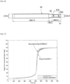
- Fig. 16 and Table 1 show the overview and dimensions of the floating model 40.
- the model is scaled down to 1/36.11 of the assumed body (2MW generator).
- the model was made mainly with polyvinyl chloride pipes, and was adjusted in weight and center-of-gravity height by attaching iron plates to the upper part and the lower part of the floating body.
- markers 41, 42 for use in measuring swaying were respectively attached at two positions, 65 mm and 418 mm away from the upper end of the floating body.
- the experiment in water tank was conducted in a test tank (width: 24.4 m, length: 38.8 m, depth during experiment: 1.824 m).
- the floating model 40 was moored at the center of the water tank.
- the upper part of the floating body was moored from an auxiliary water tank cart, and the lower part was moored from one side of the water tank.
- the mooring was adjusted in advance so that the behavior of the floating model 40 is not hindered by the mooring force.
- the floating model 40 was subjected to attitude measurement using the motion capture system (Qualysis) capable of capturing real time motions of the makers 41, 42.
- the four cameras (Qualysis 5+; 4 MP, 2048x2048 pixels, 180fps) installed beside the water tank captured the motions of the two markers 41, 42 attached to the floating model 40, and output data as spatial coordinate values every 0.02 seconds (50 Hz).
- the inclination angle formed between the central axis of the floating body and the water surface was calculated based on the converted coordinate values, and was referred to as a pitch angle.
- the ballast water was injected first into the upper part of the floating body through a hose.
- the pump used was Smoothflow Pump made by Tacmina (maximum discharge rate: 1.08 L/min, maximum discharge pressure: 1 MPa).
- the flow rate during the experiment was set at 0.73 L/min (equivalent to 5.7 m 3 /min in the actual body).
- ADAMS mechanical analysis software
- Fig. 17 shows the comparison between the experimental results in the upright raising and the simulation analysis results by means of ADAMS.
- the origin is set on the bottom surface of the floating body
- the upward Z-axis is set along the central axis of the floating body
- the X and Y axes are set to be perpendicular to the Z-axis.
- Fig. 17 shows that the simulation analysis results by means of ADAMS successfully simulate the experimental results (Experminent No. 1).
Landscapes
- Engineering & Computer Science (AREA)
- Mechanical Engineering (AREA)
- Chemical & Material Sciences (AREA)
- Combustion & Propulsion (AREA)
- Ocean & Marine Engineering (AREA)
- Sustainable Development (AREA)
- Life Sciences & Earth Sciences (AREA)
- Sustainable Energy (AREA)
- Transportation (AREA)
- General Engineering & Computer Science (AREA)
- Architecture (AREA)
- Civil Engineering (AREA)
- Structural Engineering (AREA)
- Fluid Mechanics (AREA)
- Physics & Mathematics (AREA)
- Wind Motors (AREA)
Abstract
Description
- The present invention relates to a method for raising floating body for spar-type offshore wind power generation facility with respect to a floating body to be installed at sea in a relatively deep water area.
- In an example,
Patent Document 1 to be described below discloses an offshore wind power generation facility configured with a floating body, a mooring cable, a tower, a nacelle installed at the top of the tower, and a plurality of blades. The floating body is a spar-type floating structure, which includes a lower concrete floating structure formed by stacking a plurality of concrete precast cylindrical bodies in the height direction, and tightly connecting and integrating them with PC steel members, and an upper steel floating structure connected above the lower concrete floating structure. The "spar-type" herein refers to a cylindrical floating structure formed in a long slender shape like a bar-type fishing float. - In the case where the spar-type offshore wind power generation facility is installed at sea, the facility is preferably constructed in a calm bay. However, the draft (submerged part) of the floating body is deep, approx. 70 meters or more, while a water depth in a bay is generally shallower than the depth above. Accordingly, the construction in a bay is difficult. For this reason, in the case where the spar-type offshore wind power generation facility is installed, as disclosed in
Patent Document 2, the floating body is either floated sideways at sea close to a construction yard and towed to an installation site by a tugboat, or mounted on a barge and towed to the installation site. The floating body is thereafter slowly raised upright, by injecting ballast water, and gradually delivering from a winch the wire attached to the bottom of the floating body. -
- [Patent Document 1]
Japanese Patent Publication No. 5274329 - [Patent Document 2]
Japanese Patent Application Laid-Open Publication No. 2012-201219 - The floating body is raised upright by assisting the body by means of the wire delivered from the winch, so as to prevent the floating body from rapidly rising upright at a certain point during when the ballast water is injected. The inertial force of the floating body causes swaying (vibration) when the floating body is brought into the upright state, whereby the floating body or its associated facility may be damaged. Therefore, the work of raising a floating body at sea is dangerous, and requires utmost caution and carefulness.
- The major purpose of the present invention is to provide a method for safely and efficiently raising a floating body for a spar-type offshore wind power generation facility upright by injecting ballast water at sea.
- In order to solve the problem above, the present invention according to
claim 1 provides a method for raising floating body for spar-type offshore wind power generation facility, which is performed to raise upright a floating body for a spar-type offshore wind power generation facility floating sideways by injecting ballast water at sea, including - a first step of decentering a center of gravity of the floating body for the spar-type offshore wind power generation facility by means of a center-of-gravity decentering means, and
- a second step of injecting the ballast water to raise the floating body for the spar-type offshore wind power generation facility upright.
- The invention disclosed in
claim 1 is a first embodied raising method according to the present invention. Specifically, the floating body is raised upright by, in the first step, beforehand decentering the center of gravity of the floating body for the spar-type offshore wind power generation facility by means of the center-of-gravity decentering means. As will be described later in Example, the beforehand decentering of the center of gravity slows the rising motion to which the floating body is shifted from the state of floating sideways by injecting the ballast water, and further reduces swaying in size of the floating body after becoming close to the upright state. The "decentering of the center of gravity" herein means the shift of the center of gravity of the floating body not only in the direction along the longitudinal central axis of the floating body but also in the plane direction perpendicular to the longitudinal central axis of the floating body. - Accordingly, the present invention enables to safely and efficiently raise upright the floating body for the super-type offshore wind power generation facility by injecting the ballast water at sea.
- The present invention according to
claim 2 provides a method for raising floating body for spar-type offshore wind power generation facility, which is performed to raise upright a floating body for a spar-type offshore wind power generation facility floating sideways by injecting ballast water at sea, including - a first step of decentering a center of gravity of the floating body for the spar-type offshore wind power generation facility by means of a center-of-gravity decentering means,
- a second step of injecting the ballast water to start to raise the floating body for the spar-type offshore wind power generation facility upright, and subsequently stopping the injection of the ballast water at a predetermined amount so as to stop the floating body for the spar-type offshore wind power generation facility in an inclined state before standing upright, and
- a third step of gradually re-injecting the ballast water to raise the floating body for the spar-type offshore wind power generation facility upright.
- The invention disclosed in
claim 2 is a second embodied raising method according to the present invention. Specifically, the floating body is raised upright by beforehand decentering the center of gravity of the floating body for the spar-type offshore wind power generation facility by means of the center-of-gravity decentering means, in the first step. The beforehand decentering of the center of gravity slows the rising motion to which the floating body is shifted from the state of floating sideways by injecting the ballast water, in the second step. - In the second step, the floating body for the spar-type offshore wind power generation facility starts the rising motion in response to the injection of the ballast water, and thereafter the injection of the ballast water is stopped at a predetermined amount so that the floating body for the spar-type offshore wind power generation facility is stopped in an inclined state before the standing upright. In the second step, since the rising motion is slowed due to the beforehand decentering of the center of gravity, the floating body is easily stopped in an inclined state before the standing upright by stopping the injection of the ballast water at a predetermined amount.
- In the last third step, the floating body for the spar-type offshore wind power generation facility is raised upright by gradually re-injecting the ballast water. In the case where the floating body is raised upright from the state being stopped at an inclined angle, the swaying just after the standing upright is mostly prevented because the inertial force acts only slightly on the floating body.
- Accordingly, the present invention enables to safely and efficiently raise the floating body for the super-type offshore wind power generation facility upright by injecting the ballast water at sea.
- As the present invention according to claim 3, in the method for raising floating body for spar-type offshore wind power generation facility disclosed in
claim - The invention disclosed in claim 3 corresponds to a first embodiment of the center-of-gravity decentering means. Specifically, the weight detachably attached to the outer surface of the floating body for the spar-type offshore wind power generation facility serves as the center-of-gravity decentering means.
- As the present invention according to
claim 4, in the method for raising floating body for spar-type offshore wind power generation facility disclosed in claim 3, the weight is attached at a position above the sea surface at a time of raising upright. - In the invention disclosed in
claim 4, the weight is attached at a position above the sea surface at a time of raising upright. After the floating body is raised upright, the weight is easily removed when it is no longer needed. - As the present invention according to
claim 5, in the method for raising floating body for spar-type offshore wind power generation facility disclosed inclaim - The invention disclosed in
claim 5 corresponds to a second embodiment of the center-of-gravity decentering means. Specifically, the solid ballast introduced in the floating body for the spar-type offshore wind power generation facility serves as the center-of-gravity decentering means. The solid ballast is generally introduced into the floating body after being raised upright. The solid ballast may be used as the means of decentering the center of gravity because it remains, unlike water, in an uneven state without moving until an inclination angle corresponds to an angle of rest (the slope angle at which the solid ballast remains stable without collapsing). Moreover, the solid ballast may be used as the center-of-gravity decentering means because the solid ballast after exceeding the angle of rest moves more slowly than water, and the decentered state is maintained while the eccentricity is gradually decreased until just before the upright state. - As described in detail above, the present invention enables to safely and efficiently raise the floating body for the spar-type offshore wind power generation facility by injecting the ballast water at sea.
-
-
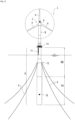
Fig. 1 is an overall side view of a spar-type floating offshore windpower generation facility 1. -
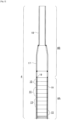
Fig. 2 is a longitudinal sectional view of afloating body 4. -
Fig. 3 illustrates a precastcylindrical body 15, whereFig. 3(A) is a longitudinal sectional view thereof,Fig. 3(B) is a plan view thereof (view along a B-B line), andFig. 3(C) is a bottom view thereof (view along a C-C line). -
Fig. 4(A) and Fig. 4(B) illustrate the procedure of tightly connecting the precastcylindrical bodies 15 with each other. -
Fig. 5 is a longitudinal sectional view illustrating the boundary between a lower concretefloating structure 4A and an upper steelfloating structure 4B. -
Fig. 6 illustrates the method for raising thefloating body 4 upright according to a first embodiment, inPart 1. -
Fig. 7 illustrates the method for raising thefloating body 4 upright according to the first embodiment, inPart 2. -
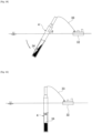
Fig. 8 illustrates the method for raising thefloating body 4 upright according to the first embodiment, in Part 3. -
Fig. 9 illustrates the method for raising thefloating body 4 upright according to the first embodiment, inPart 4. -
Fig. 10 illustrates the method for constructing the offshore windpower generation facility 1 after the raising, inPart 1. -
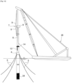
Fig. 11 illustrates the method for constructing the offshore windpower generation facility 1 after the raising, inPart 2. -
Fig. 12 illustrates the method for raising the floatingbody 4 upright according to a second embodiment, inPart 1. -
Fig. 13 illustrates the method for raising the floatingbody 4 upright according to the second embodiment, inPart 2. -
Fig. 14 illustrates the method for raising the floatingbody 4 upright according to the second embodiment, in Part 3. -
Fig. 15 illustrates the method for raising the floatingbody 4 upright according to the second embodiment, inPart 4. -
Fig. 16 is a side view of a floatingmodel 40. -
Fig. 17 is a graph showing comparison between experimental values and analysis results. -
Fig. 18 is a graph showing effects of eccentricity of center-of-gravity of a floating body on response (rising motion). - Hereinafter, the embodiments of the present invention will be described in detail with reference to the drawings.
- Prior to describing the "method for raising floating body for spar-type offshore wind power generation facility" according to the present invention, a structural example of the spar-type floating offshore wind
power generation facility 1 will be described in detail, with reference toFig. 1 to Fig. 5 . - As shown in
Fig. 1 , the offshore windpower generation facility 1 is configured with the cylindrical-shaped floatingbody 4, amooring cable 5, atower 6, and awind turbine 7 configured with anacelle 8 installed at the top of thetower 6 and a plurality ofblades - As shown in
Fig. 2 , the floatingbody 4 is configured with the lowerconcrete floating structure 4A, which is formed by stacking the plurality of precastcylindrical bodies cylindrical bodies PC steel members 19, and the uppersteel floating structure 4B connected above the lowerconcrete floating structure 4A. - The floating
body 4 has a hollow portion which allows ballast material such as water, gravel, fine aggregate or coarse aggregate, or metal particles to be introduced into or discharged from, so that its buoyancy (draft) is adjustable. The fluid transport method having been proposed by the present applicant inJapanese patent application publication No. 2012-201217 - As shown in
Fig. 3 , the precastcylindrical bodies 15 included in the lowerconcrete floating structure 4A are the circular cylindrical precast members having the uniform cross section in the axial direction. The hollow precast members manufactured either by using the same mold or by centrifugal molding are used as the precastcylindrical bodies 15. - The wall of the precast
cylindrical body 15 includes, inside the wall surface, not only a reinforcingbar 20, but also sheaths 21, 21..., which are arranged at appropriate intervals in the circumferential direction and allow for insertion of the PC steel bars 19. Each of thesheaths sheath expansion part 21a allowing for insertion of a coupler for coupling the PC steel bars 19 to each other, at the bottom part, and has avoid space part 22 for fitting a fixing anchor plate, at the upper part. The precastcylindrical body 15 further has a plurality of hangingbrackets 23 on the upper surface. - As shown in
Fig. 4(A) , the precastcylindrical bodies 15 are tightly connected by the steps of stacking the precastcylindrical bodies cylindrical body 15 into thesheaths anchor plates 24 into thevoid space parts 22, and introducing tension to the PC steel bars 19 by means ofnut members 25 to integrate them. Grout material is injected into thesheaths 21 through grout injection holes 27 (refer toFig. 4(B) ). Each of theanchor plates 24 has ahole 24a serving as a grout injection confirmation hole. The filling of the grout material is completed when the grout material is discharged from the confirmation hole. - As shown in
Fig. 4(B) , the tight connection is further performed by the steps of, after screwingcouplers 26 to the protrusions of the PC steel bars 19 to connect them to the upper PC steel bars 19, 19..., inserting the PC steel bars 19, 19... into thesheaths cylindrical body 15, for stacking. The steps above for fixing the PC steel bars 19 according to the procedure above are sequentially repeated to achieve the stacking in the height direction. At this time, an adhesive 28 such as epoxy resin or sealing material is applied to the joint surfaces between the lower precastcylindrical body 15 and the upper precastcylindrical body 15, to ensure water cutoff performance and join the joint surfaces. - As shown in
Fig. 2 , the uppersteel floating structure 4B is configured with a steelcylindrical body 17 positioned on the relatively lower side and a steelcylindrical body 18 positioned on the relatively upper side. The lowersteel cylindrical body 17 has the lower portion having the same outer diameter as the precastcylindrical body 15, and is connected to the precastcylindrical body 15. The steelcylindrical body 17 has the upper portion formed in a truncated conical frustum gradually narrowing in diameter. - The upper steel
cylindrical body 18 is a cylindrical body having the outer diameter which is continuous from the upper outer diameter of the lowersteel cylindrical body 17, and is connected to the lowersteel cylindrical body 17 by bolting, welding, or the like (connection by bolting in the illustrated example). - The
tower 6 made of steel, concrete, or prestressed reinforced concrete (PRC) is used. Thetower 6 made of steel is preferable because it is light in total weight. The outer diameter of thetower 6 and the outer diameter of the upper steelcylindrical body 18 are substantially the same, and those outer shapes are continuous in the vertical direction without any steps or the like. In the illustrated example, aladder 13 is provided on the upper part of the upper steelcylindrical body 18, and awalkway scaffold 14 is provided in the circumferential direction substantially at the boundary between thetower 6 and the upper steelcylindrical body 18. - As shown in
Fig. 1 , a mooring point K at which the floatingbody 4 is moored by themooring cable 5 is set at a position below the sea surface and higher than a center of gravity G of the floatingbody 4. This prevents a vessel from coming into contact with themooring cable 5. Furthermore, this generates a resistance moment centered around the center of gravity G of the floatingbody 4 at the mooring point, thereby preventing the floatingbody 4 from inclining excessively, and appropriately maintaining thetower 6 in an inclined state. - The
nacelle 8 is a device equipped with a generator which converts the rotation of thewind turbine 7 into electricity, a controller which is capable of automatically changing the angle of theblade 9, and the like. - The method for raising the floating
body 4 for the spar-type offshore wind power generation facility described above will be described in detail below. - In the present invention, a floating body for a spar-type offshore wind power generation facility floating sideways is raised upright by injecting ballast water at sea, by a first step of decentering the center of gravity of the floating
body 4 for the spar-type offshore wind power generation facility by detachably attaching aweight 2 thereto, and a second step of injecting ballast water to raise the floatingbody 4 for the spar-type floating offshore wind power generation facility upright. Theweight 2 is included in the "center-of-gravity decentering means" according to the present invention. Hereinafter, the configuration will be specifically described in detail with reference toFig. 6 to Fig. 10 . - When the floating
body 4 is manufactured in a predetermined quay area, the floatingbody 4 is loaded on asemi-submersible barge 30 while adjusting ballast. At this time, theweight 2 for decentering the center of gravity of the floatingbody 4 is attached detachably to the floatingbody 4. For the convenience of detaching, it is desirable that theweight 2 is attached to the outer surface of the floatingbody 4 at a position above the sea surface when the floatingbody 4 is raised upright. The decentering of the center of gravity herein means the shift of the center of gravity of the floatingbody 4 in not only the direction along the longitudinal central axis of the floating body 4 (Z axis) but also the plane direction perpendicular to the longitudinal central axis of the floating body 4 (X-Y plane). Accordingly, theweight 2 may be provided at one position on the outer surface of the floatingbody 4, and it is not desirable that theweight 2 is provided at even number of symmetrical positions on the outer surface of the floating body 4 (for example, positions at 180 degrees or at 90 degrees). - As shown in
Fig. 6 , atugboat 31 performs towing to an offshore installation site. The floatingbody 4 is floated off (floating and launching) by injecting water into thesemi-submersible barge 30 to be semi-submerged, floating the floatingbody 4 at sea, and separating thesemi-submersible barge 30 from the floatingbody 4. - As shown in
Fig. 7 , aballast barge 32 equipped with a ballast water pumping facility is brought close to the floatingbody 4 having been floated off, so as to allow for water injection, and aballast hose 33 is inserted into the floatingbody 4 to supply ballast water. - When a predetermined amount of ballast water is injected into the floating
body 4, the pitch angle of the floating body 4 (an inclination angle θ formed between the longitudinal axis of the floatingbody 4 and the water surface) increases gradually but surely, at first. As shown inFig. 8 , at a certain point, the floatingbody 4 starts rapid rising motion. Then, as shown inFig. 9 , the floatingbody 4 is raised substantially vertically. - In the present invention, as in Example to be described later, the beforehand decentering of the center of gravity of the floating
body 4 for the spar-type offshore wind power generation facility by means of thewaist 2 attached slows the rising motion to which the floating body is shifted from the state of floating sideways by injecting the ballast water, and further reduces swaying in size of the floating body after becoming close to the upright state. Accordingly, the floatingbody 4 is safely and efficiently raised upright by injecting the ballast water. - After the floating
body 4 is raised upright, theweight 2 is removed as shown inFig. 10 . Asolid ballast 34 is introduced into the floatingbody 4. Thesolid ballast 34 is a granular substance having higher specific gravity than water, and is preferably one or combination of a plurality of minerals including sand, gravel, and barite, and metals including iron, and lead in power or granular form. Adjusting the material of thesolid ballast 34 allows for introduction of appropriate specific gravity. The draft of the floatingbody 4 is adjusted while balancing with the ballast water. - As shown in
Fig. 10 , theladder 13 is attached on the upper part of the floatingbody 4, and thewalkway scaffold 14 is provided. One end of themooring cable 5 is securely connected to the floatingbody 4, and the other end is securely connected to the anchor submerged in the seabed to stabilize the floatingbody 4. - As shown in
Fig. 11 , thetower 6, and thewind turbine 7 connected to the top of thetower 6, including thenacelle 8 and the plurality ofblades body 4 while being suspended by the crane installed on aheavy lift vessel 35. - The second embodiment of the method for raising the floating
body 4 for the spar-type offshore wind power generation facility will be described in detail below. - In the present second embodiment, the floating
body 4 for the spar-type offshore wind power generation facility floating sideways is raised upright by injecting ballast water at sea, by - a first step of decentering the center of gravity of the floating
body 4 for the spar-type floating offshore wind power generation facility by means of the center-of-gravity decentering means, - a second step of injecting ballast water to start to raise the floating
body 4 for the spar-type floating offshore wind power generation facility upright, and subsequently stopping the injection of the ballast water at a predetermined amount so as to stop the floatingbody 4 in an inclined state before the standing upright, and - a third step of gradually re-injecting the ballast water to raise the floating
body 4 for the spar-type offshore wind power generation facility upright. - In comparison with the "method for raising floating body (Part 1)" described above, the present method is different only in that, in the middle of the rapid rising motion of the floating
body 4 after its start, the ballast water injection is stopped so as to stop the floatingbody 4 in an inclined state before the standing upright. - As described above, as the center of gravity decentering means, the
weight 2 may be attached, or thesolid ballast 34 may be introduced into the floatingbody 4. The beforehand decentering of the center of gravity slows the rising motion, thereby allowing the floatingbody 4 to be stopped in an inclined state before the standing upright. In the third step, the ballast water is gradually re-injected into the floatingbody 4 having been temporarily stopped in an inclined state, so as to raise the floatingbody 4 upright. This allows for safer and more efficient operation because the inertial force occurring when the floatingbody 4 is raised upright only slightly makes the floatingbody 4 sway. - In the case of the
solid ballast 34 to be described later serving as the center-of-gravity decentering means, the inclination angle θ at which the floatingbody 4 is stopped in an inclined state before the standing upright is preferably an angle equal to or less than the angle of rest of thesolid ballast 34. - In the embodiment described above, the
weight 2 serves as the center-of-gravity decentering means. Alternatively, thesolid ballast 34 may serve as the center-of-gravity decentering means. The case will be described in detail with reference toFig. 12 to Fig. 15 . - As shown in
Fig. 12 , when the floatingbody 4 is manufactured in a predetermined quay area, the floating body is loaded on thesemi-submersible barge 30 while adjusting ballast. Thesolid ballast 34 is then introduced into the loaded floatingbody 4. Alternatively, thesolid ballast 34 may be introduced prior to the loading on thesemi-submersible barge 30. Thesolid ballast 34 is in a flowable state without being held by any means. Therefore, since the floatingbody 4 is loaded sideways on thesemi-submersible barge 30, thesolid ballast 34 spreads horizontally. In other words, in the floatingbody 4 positioned sideways, the center of gravity of the floatingbody 4 is decentered by thesolid ballast 34. - As shown in
Fig. 12 , after being towed by thetugboat 31 to an offshore installation site, the floatingbody 4 is floated at sea. The floatingbody 4 is floated off (floating and launching) by injecting water into thesemi-submersible barge 30 to be semi-submerged, floating the floatingbody 4 at sea, and separating thesemi-submersible barge 30 from the floatingbody 4. - As shown in
Fig. 14 , theballast barge 32 equipped with a ballast water pumping facility is brought close to the floatingbody 4 having been floated off, so as to allow for water injection, and theballast hose 33 is inserted inside the floatingbody 4 to supply ballast water. - When a predetermined amount of ballast water is injected into the floating
body 4, the pitch angle of the floating body 4 (the angle θ formed between the longitudinal line of the floating body and the water surface) increases gradually but surely, at first. As shown inFig. 14 , at a certain point, the floatingbody 4 starts rapid rising motion. Then, as shown inFig. 15 , the floatingbody 4 is raised substantially vertically. - In the floating
body 4 positioned sideways, the center of gravity of the floatingbody 4 is decentered by the solid ballast introduced inside. The pitch angle θ of the floatingbody 4 gradually increases as the ballast water is injected. Even when the floatingbody 4 is inclined, thesolid ballast 34 remains in an uneven state without moving until the inclination angle θ corresponds to the angle of rest (the slope angle at which thesolid ballast 34 remains stable without collapsing). When the inclination angle θ of the floatingbody 4 exceeds the angle of rest, thesolid ballast 34 starts to move. Due to its slow moving-speed compared to water, thesolid ballast 34 flows gradually while taking time until the upright state, and finally the bottom part of the floatingbody 4 is filled with thesolid ballast 34. This releases the decentering of the center of gravity. Since the decentered state is maintained while the eccentricity is gradually decreased until just before the upright state, the rising motion of the floatingbody 4 is slow, and the swaying after becoming close to the upright state is reduced. Accordingly, the floatingbody 4 is safely and efficiently raised by injecting the ballast water. - After the floating
body 4 is raised upright, the draft of the floatingbody 4, in which a predetermined amount of thesolid ballast 34 has already been introduced, is adjusted by injecting the ballast water. - The following procedure for constructing the offshore wind
power generation facility 1 after the raising upright is omitted because it has already been described in the first embodiment. - 1: The two means serving as the center-of-gravity decentering means have been described: one using the
weight 2 attached to the outer surface of the floatingbody 4; and the other introducing thesolid ballast 34 into the floatingbody 4. The two means may be used in combination. The pre-introduction of thesolid ballast 34 in the floatingbody 4 eliminates the needs of introduction of the solid ballast offshore, and leads to more efficient work. - In the present invention, experiments and analyses were conducted to verify the effects of decentering the center of gravity of the floating
body 4 by means of the center-of-gravity decentering means (theweight 2 or the solid ballast 34), and those will be described in detail below. -
Fig. 16 and Table 1 show the overview and dimensions of the floatingmodel 40. The model is scaled down to 1/36.11 of the assumed body (2MW generator). The model was made mainly with polyvinyl chloride pipes, and was adjusted in weight and center-of-gravity height by attaching iron plates to the upper part and the lower part of the floating body. As shown inFig. 16 ,markers [Table 1] Upper part Length 448 mm Outer diameter 132.9 mm Conical part Length 166.2 mm Outer diameter 132.9 to 216 mm Lower part Length 1861.5 mm Outer diameter 216 mm Wall thickness 11 mm Bottom thickness 91 mm Total weight 46.25 kg Center-of-gravity Position of 788 mm away from bottom of floating body - The experiment in water tank was conducted in a test tank (width: 24.4 m, length: 38.8 m, depth during experiment: 1.824 m).
- The floating
model 40 was moored at the center of the water tank. The upper part of the floating body was moored from an auxiliary water tank cart, and the lower part was moored from one side of the water tank. The mooring was adjusted in advance so that the behavior of the floatingmodel 40 is not hindered by the mooring force. - The floating
model 40 was subjected to attitude measurement using the motion capture system (Qualysis) capable of capturing real time motions of themakers Qualysis 5+; 4 MP, 2048x2048 pixels, 180fps) installed beside the water tank captured the motions of the twomarkers model 40, and output data as spatial coordinate values every 0.02 seconds (50 Hz). The inclination angle formed between the central axis of the floating body and the water surface was calculated based on the converted coordinate values, and was referred to as a pitch angle. - The ballast water was injected first into the upper part of the floating body through a hose. The pump used was Smoothflow Pump made by Tacmina (maximum discharge rate: 1.08 L/min, maximum discharge pressure: 1 MPa). The flow rate during the experiment was set at 0.73 L/min (equivalent to 5.7 m3/min in the actual body).
- The analysis was conducted by using a program (ADAMS: mechanical analysis software) to obtain the attitude of the floating body in the state of having arbitrary ballast water therein, by taking into account six forces: gravity acting on the floating body itself; gravity acting on the internal ballast water; gravity acting on the weight for decentering center-of-gravity; buoyancy acting on the floating body; and additional mass force and resistance force received by the moving floating body from external fluid, on the basis of the dynamic equilibrium conditions between the six forces and the inertial force occurring when the floating body moves.
-
Fig. 17 shows the comparison between the experimental results in the upright raising and the simulation analysis results by means of ADAMS. In this case, the coordinates of the center of gravity of the floating body itself free from ballast water were set at (Xg, Yg, Zg) = (0.0022 m, 0.0 m, 0.788 m) with respect to a floating body fixed coordinate system. In the floating body fixed coordinate system, the origin is set on the bottom surface of the floating body, the upward Z-axis is set along the central axis of the floating body, and the X and Y axes are set to be perpendicular to the Z-axis. -
Fig. 17 shows that the simulation analysis results by means of ADAMS successfully simulate the experimental results (Experminent No. 1). - Since, according to 3.1, the response of the floating body in the upright raising was accurately predicted through the simulation by means of ADAMS, the effects of decentering the center of gravity of the floating body on the response are investigated through the simulation. The response of the floating body in the upright raising was simulated with respect to the following three cases with the values of Xg varied: the case of no eccentricity where Xg = 0.0 m; the case of the weight attached in the same conditions as the experimental conditions where Xg = 0.0022 m; and the case of the doubled eccentricity of the center of gravity where Xg = 0.0044 m.
Fig. 18 shows the results. -
Fig. 18 shows that, in the case of no eccentricity where Xg = 0.0 m, the rising motion was rapid, and large swaying occurred after the upright state. In the case of the eccentricity of the center of gravity where Xg = 0.0022 m, and in the case of the doubled eccentricity of the center of gravity, the rising motion was slow, and only small swaying occurred even after becoming close to the upright state. The comparison between the case of the eccentricity of the center of gravity where Xg = 0.0022 m and the case of the doubled eccentricity of the center of gravity where Xg = 0.0044 m shows that as the eccentricity is increased, the rising motion is slower, and the swaying after the standing upright is reduced. - Based on the results above, it is found that in raising the floating body upright by injecting water, the decentering of the center of gravity leads to slower rising motion, and reduces swaying after the standing upright.
- 1: SPAR-TYPE FLOATING OFFSHORE WIND POWER GENERATION FACILITY, 4: FLOATING BODY, 4A: LOWER CONCRETE FLOATING STRUCTURE, 4B: UPPER STEEL FLOATING STRUCTURE, 5: MOORING CABLE, 6: TOWER, 7, (7'): WIND TURBINE, 8: NACELLE, 9: BLADE, 15: PRECAST CYLINDRICAL BODY, 17, 18: STEEL CYLINDRICAL BODY, 19: PC STEEL BAR, 30: SEMI-SUBMERSIBLE BARGE, 31: TUGBOAT, 32: BALLAST BARGE, 33: BALLAST HOSE, 34: SOLID BALLAST, 35: HEAVY LIFT VESSEL, 40: FLOATING MODEL, 41, 42: MARKER
Claims (5)
- A method for raising floating body for spar-type offshore wind power generation facility to be performed to raise upright a floating body for a spar-type offshore wind power generation facility floating sideways by injecting ballast water at sea, the method comprising:a first step of decentering a center of gravity of the floating body for the spar-type offshore wind power generation facility by means of a center-of-gravity decentering means; anda second step of injecting ballast water to raise upright the floating body for the spar-type offshore wind power generation facility.
- A method for raising floating body for spar-type offshore wind power generation facility to be performed to raise upright a floating body for a spar-type offshore wind power generation facility floating sideways by injecting ballast water at sea, the method comprising:a first step of decentering a center of gravity of the floating body for the spar-type offshore wind power generation facility by means of a center-of-gravity decentering means;a second step of injecting ballast water to start to raise upright the floating body for the spar-type offshore wind power generation facility, and subsequently stopping the injection of the ballast water at a predetermined amount so as to stop the floating body for the spar-type offshore wind power generation facility in an inclined state before standing upright; anda third step of gradually re-injecting the ballast water to raise upright the floating body for the spar-type offshore wind power generation facility.
- The method for raising floating body for spar-type offshore wind power generation facility according to claim 1 or 2, wherein
the center-of-gravity decentering means is a weight detachably attached to an outer surface of the floating body for the spar-type offshore wind power generation facility. - The method for raising floating body for spar-type offshore wind power generation facility according to claim 3, wherein
the weight is attached so as to be above sea surface in an upright state. - The method for raising floating body for spar-type offshore wind power generation facility according to claim 1 or 2, wherein
the center-of-gravity decentering means is a solid ballast introduced in the floating body for the spar-type offshore wind power generation facility.
Applications Claiming Priority (2)
| Application Number | Priority Date | Filing Date | Title |
|---|---|---|---|
| JP2021054613 | 2021-03-29 | ||
| PCT/JP2022/014408 WO2022210358A1 (en) | 2021-03-29 | 2022-03-25 | Method for raising floating body for spar-type offshore wind power generation facility |
Publications (2)
| Publication Number | Publication Date |
|---|---|
| EP4317682A1 true EP4317682A1 (en) | 2024-02-07 |
| EP4317682A4 EP4317682A4 (en) | 2025-04-23 |
Family
ID=83459024
Family Applications (1)
| Application Number | Title | Priority Date | Filing Date |
|---|---|---|---|
| EP22780571.0A Pending EP4317682A4 (en) | 2021-03-29 | 2022-03-25 | Method for raising floating body for spar-type offshore wind power generation facility |
Country Status (6)
| Country | Link |
|---|---|
| US (1) | US20240166313A1 (en) |
| EP (1) | EP4317682A4 (en) |
| JP (1) | JP7663913B2 (en) |
| AU (1) | AU2022248613A1 (en) |
| CA (1) | CA3213428A1 (en) |
| WO (1) | WO2022210358A1 (en) |
Families Citing this family (1)
| Publication number | Priority date | Publication date | Assignee | Title |
|---|---|---|---|---|
| KR102924760B1 (en) * | 2023-08-16 | 2026-02-09 | 세호엔지니어링 주식회사 | A device for testing mooring system of floating offshore wind turbine and a method thereof |
Family Cites Families (18)
| Publication number | Priority date | Publication date | Assignee | Title |
|---|---|---|---|---|
| US3921558A (en) * | 1974-09-16 | 1975-11-25 | Vickers Ltd | Floatable vessel |
| US6092483A (en) * | 1996-12-31 | 2000-07-25 | Shell Oil Company | Spar with improved VIV performance |
| US6227137B1 (en) * | 1996-12-31 | 2001-05-08 | Shell Oil Company | Spar platform with spaced buoyancy |
| US6263824B1 (en) * | 1996-12-31 | 2001-07-24 | Shell Oil Company | Spar platform |
| US6012873A (en) * | 1997-09-30 | 2000-01-11 | Copple; Robert W. | Buoyant leg platform with retractable gravity base and method of anchoring and relocating the same |
| WO2003004869A1 (en) * | 2001-07-06 | 2003-01-16 | Vestas Wind Systems A/S | Offshore wind turbine with floating foundation |
| US7197999B2 (en) * | 2004-10-08 | 2007-04-03 | Technip France | Spar disconnect system |
| US7377225B2 (en) * | 2006-08-07 | 2008-05-27 | Technip France | Spar-type offshore platform for ice flow conditions |
| SG158837A1 (en) * | 2008-08-01 | 2010-02-26 | Keppel Offshore & Marine Techn | A system and method for mooring of offshore structures |
| GB2462602B (en) * | 2008-08-11 | 2012-09-19 | Statoilhydro Asa | Method and apparatus for towing offshore wind turbines |
| JP5274329B2 (en) | 2009-03-24 | 2013-08-28 | 戸田建設株式会社 | Offshore wind power generation facility and its construction method |
| JP5330048B2 (en) * | 2009-03-24 | 2013-10-30 | 戸田建設株式会社 | Installation method of offshore wind power generation equipment |
| US9457873B2 (en) * | 2010-12-21 | 2016-10-04 | Lockheed Martin Corporation | On-site fabricated fiber-composite floating platforms for offshore applications |
| JP5738644B2 (en) | 2011-03-25 | 2015-06-24 | 戸田建設株式会社 | Installation method of offshore wind power generation equipment |
| JP5738642B2 (en) | 2011-03-25 | 2015-06-24 | 戸田建設株式会社 | Installation method of offshore wind power generation equipment |
| JP6108445B2 (en) * | 2013-03-13 | 2017-04-05 | 戸田建設株式会社 | Floating offshore wind power generation facility |
| WO2014187977A1 (en) * | 2013-05-23 | 2014-11-27 | Offshore Engineering Services Llc | Deep-draft floating foundation for wind turbine with clustered hull and compartmented ballast section and self-erecting pivoting installation process thereof |
| JP5732150B1 (en) | 2014-01-29 | 2015-06-10 | サノヤス造船株式会社 | Tower-type floating structure and installation method thereof |
-
2022
- 2022-03-25 AU AU2022248613A patent/AU2022248613A1/en active Pending
- 2022-03-25 US US18/283,082 patent/US20240166313A1/en active Pending
- 2022-03-25 EP EP22780571.0A patent/EP4317682A4/en active Pending
- 2022-03-25 JP JP2023511169A patent/JP7663913B2/en active Active
- 2022-03-25 WO PCT/JP2022/014408 patent/WO2022210358A1/en not_active Ceased
- 2022-03-25 CA CA3213428A patent/CA3213428A1/en active Pending
Also Published As
| Publication number | Publication date |
|---|---|
| AU2022248613A1 (en) | 2023-08-24 |
| WO2022210358A1 (en) | 2022-10-06 |
| CA3213428A1 (en) | 2022-10-06 |
| JPWO2022210358A1 (en) | 2022-10-06 |
| EP4317682A4 (en) | 2025-04-23 |
| JP7663913B2 (en) | 2025-04-17 |
| US20240166313A1 (en) | 2024-05-23 |
Similar Documents
| Publication | Publication Date | Title |
|---|---|---|
| JP5022976B2 (en) | Spar-type floating structure for offshore wind power generation, its manufacturing method, and its installation method | |
| JP6270527B2 (en) | Installation method of offshore wind power generation equipment | |
| KR102155394B1 (en) | Floating offshore wind power generation facility | |
| CN100473824C (en) | Foundation for an offshore wind energy plant | |
| US8689721B2 (en) | Vertically installed spar and construction methods | |
| CN109629568A (en) | The process for sinking of the steady stake platform of offshore wind farm jacket foundation steel pipe pile floating | |
| EP3849894B1 (en) | Floating wind turbine generator installation | |
| TW202037811A (en) | Semi-submersible type floating substructure and wind turbine offshore installation method using semi-submersible type floating substructure | |
| JP5738643B2 (en) | Installation method of offshore wind power generation equipment | |
| CN107399411A (en) | The ballast control system of floating wind turbine platform and vertically-aligned adjusting method | |
| CN1767976A (en) | A vessel for transporting wind turbines, methods of moving a wind turbine, and a wind turbine for an off-shore wind farm | |
| JP2010223114A5 (en) | ||
| DE20100588U1 (en) | Off-shore wind turbine | |
| CN116080842A (en) | Integral transportation and installation method of floating device of offshore wind farm | |
| US20240166313A1 (en) | Method for raising floating body for spar-type offshore wind power generation facility | |
| CN115520336B (en) | Floating wind turbine foundation, offshore wind power system and installation method of offshore wind power system | |
| JP5738642B2 (en) | Installation method of offshore wind power generation equipment | |
| CN211340843U (en) | Slip casting formula anchor foundation based on torpedo anchor construction | |
| JP7642216B2 (en) | Construction method for spar-type offshore wind power generation equipment | |
| JP6937627B2 (en) | Offshore wind power generation equipment and its construction method | |
| CN216185835U (en) | Deep water grouting anchor | |
| CN106703064A (en) | Anchoring foundation with multiple rows of steel piles and waste tires symmetrically distributed and construction method thereof | |
| CN222456107U (en) | Construction device for weir first and pile later in deep water without covering layer in reservoir area | |
| CN119663862B (en) | Offshore hoisting, positioning and installing construction method for large-scale conduit supporting frame | |
| JP2024179238A (en) | How to build a spar-type offshore wind power generation facility |
Legal Events
| Date | Code | Title | Description |
|---|---|---|---|
| STAA | Information on the status of an ep patent application or granted ep patent |
Free format text: STATUS: THE INTERNATIONAL PUBLICATION HAS BEEN MADE |
|
| PUAI | Public reference made under article 153(3) epc to a published international application that has entered the european phase |
Free format text: ORIGINAL CODE: 0009012 |
|
| STAA | Information on the status of an ep patent application or granted ep patent |
Free format text: STATUS: REQUEST FOR EXAMINATION WAS MADE |
|
| 17P | Request for examination filed |
Effective date: 20230912 |
|
| AK | Designated contracting states |
Kind code of ref document: A1 Designated state(s): AL AT BE BG CH CY CZ DE DK EE ES FI FR GB GR HR HU IE IS IT LI LT LU LV MC MK MT NL NO PL PT RO RS SE SI SK SM TR |
|
| DAV | Request for validation of the european patent (deleted) | ||
| DAX | Request for extension of the european patent (deleted) | ||
| A4 | Supplementary search report drawn up and despatched |
Effective date: 20250325 |
|
| RIC1 | Information provided on ipc code assigned before grant |
Ipc: F03D 13/10 20160101ALN20250319BHEP Ipc: B63B 1/04 20060101ALI20250319BHEP Ipc: B63B 39/03 20060101ALI20250319BHEP Ipc: B63B 35/00 20200101ALI20250319BHEP Ipc: B63B 77/10 20200101ALI20250319BHEP Ipc: F03D 13/25 20160101AFI20250319BHEP |
|
| STAA | Information on the status of an ep patent application or granted ep patent |
Free format text: STATUS: EXAMINATION IS IN PROGRESS |
|
| 17Q | First examination report despatched |
Effective date: 20260323 |