EP4317662A1 - Fan case assembly for turbofan engine - Google Patents
Fan case assembly for turbofan engine Download PDFInfo
- Publication number
- EP4317662A1 EP4317662A1 EP21934966.9A EP21934966A EP4317662A1 EP 4317662 A1 EP4317662 A1 EP 4317662A1 EP 21934966 A EP21934966 A EP 21934966A EP 4317662 A1 EP4317662 A1 EP 4317662A1
- Authority
- EP
- European Patent Office
- Prior art keywords
- panel
- fan case
- elastic body
- fan
- axial
- Prior art date
- Legal status (The legal status is an assumption and is not a legal conclusion. Google has not performed a legal analysis and makes no representation as to the accuracy of the status listed.)
- Pending
Links
Images




Classifications
-
- F—MECHANICAL ENGINEERING; LIGHTING; HEATING; WEAPONS; BLASTING
- F02—COMBUSTION ENGINES; HOT-GAS OR COMBUSTION-PRODUCT ENGINE PLANTS
- F02K—JET-PROPULSION PLANTS
- F02K3/00—Plants including a gas turbine driving a compressor or a ducted fan
- F02K3/02—Plants including a gas turbine driving a compressor or a ducted fan in which part of the working fluid by-passes the turbine and combustion chamber
- F02K3/04—Plants including a gas turbine driving a compressor or a ducted fan in which part of the working fluid by-passes the turbine and combustion chamber the plant including ducted fans, i.e. fans with high volume, low pressure outputs, for augmenting the jet thrust, e.g. of double-flow type
- F02K3/06—Plants including a gas turbine driving a compressor or a ducted fan in which part of the working fluid by-passes the turbine and combustion chamber the plant including ducted fans, i.e. fans with high volume, low pressure outputs, for augmenting the jet thrust, e.g. of double-flow type with front fan
-
- F—MECHANICAL ENGINEERING; LIGHTING; HEATING; WEAPONS; BLASTING
- F02—COMBUSTION ENGINES; HOT-GAS OR COMBUSTION-PRODUCT ENGINE PLANTS
- F02K—JET-PROPULSION PLANTS
- F02K1/00—Plants characterised by the form or arrangement of the jet pipe or nozzle; Jet pipes or nozzles peculiar thereto
- F02K1/44—Nozzles having means, e.g. a shield, reducing sound radiation in a specified direction
-
- F—MECHANICAL ENGINEERING; LIGHTING; HEATING; WEAPONS; BLASTING
- F01—MACHINES OR ENGINES IN GENERAL; ENGINE PLANTS IN GENERAL; STEAM ENGINES
- F01D—NON-POSITIVE DISPLACEMENT MACHINES OR ENGINES, e.g. STEAM TURBINES
- F01D21/00—Shutting-down of machines or engines, e.g. in emergency; Regulating, controlling, or safety means not otherwise provided for
- F01D21/04—Shutting-down of machines or engines, e.g. in emergency; Regulating, controlling, or safety means not otherwise provided for responsive to undesired position of rotor relative to stator or to breaking-off of a part of the rotor, e.g. indicating such position
- F01D21/045—Shutting-down of machines or engines, e.g. in emergency; Regulating, controlling, or safety means not otherwise provided for responsive to undesired position of rotor relative to stator or to breaking-off of a part of the rotor, e.g. indicating such position special arrangements in stators or in rotors dealing with breaking-off of part of rotor
-
- F—MECHANICAL ENGINEERING; LIGHTING; HEATING; WEAPONS; BLASTING
- F01—MACHINES OR ENGINES IN GENERAL; ENGINE PLANTS IN GENERAL; STEAM ENGINES
- F01D—NON-POSITIVE DISPLACEMENT MACHINES OR ENGINES, e.g. STEAM TURBINES
- F01D25/00—Component parts, details, or accessories, not provided for in, or of interest apart from, other groups
- F01D25/24—Casings; Casing parts, e.g. diaphragms, casing fastenings
- F01D25/26—Double casings; Measures against temperature strain in casings
-
- F—MECHANICAL ENGINEERING; LIGHTING; HEATING; WEAPONS; BLASTING
- F01—MACHINES OR ENGINES IN GENERAL; ENGINE PLANTS IN GENERAL; STEAM ENGINES
- F01D—NON-POSITIVE DISPLACEMENT MACHINES OR ENGINES, e.g. STEAM TURBINES
- F01D25/00—Component parts, details, or accessories, not provided for in, or of interest apart from, other groups
- F01D25/28—Supporting or mounting arrangements, e.g. for turbine casing
-
- F—MECHANICAL ENGINEERING; LIGHTING; HEATING; WEAPONS; BLASTING
- F02—COMBUSTION ENGINES; HOT-GAS OR COMBUSTION-PRODUCT ENGINE PLANTS
- F02C—GAS-TURBINE PLANTS; AIR INTAKES FOR JET-PROPULSION PLANTS; CONTROLLING FUEL SUPPLY IN AIR-BREATHING JET-PROPULSION PLANTS
- F02C7/00—Features, components parts, details or accessories, not provided for in, or of interest apart form groups F02C1/00 - F02C6/00; Air intakes for jet-propulsion plants
- F02C7/24—Heat or noise insulation
-
- F—MECHANICAL ENGINEERING; LIGHTING; HEATING; WEAPONS; BLASTING
- F02—COMBUSTION ENGINES; HOT-GAS OR COMBUSTION-PRODUCT ENGINE PLANTS
- F02K—JET-PROPULSION PLANTS
- F02K1/00—Plants characterised by the form or arrangement of the jet pipe or nozzle; Jet pipes or nozzles peculiar thereto
- F02K1/78—Other construction of jet pipes
- F02K1/82—Jet pipe walls, e.g. liners
- F02K1/827—Sound absorbing structures or liners
-
- F—MECHANICAL ENGINEERING; LIGHTING; HEATING; WEAPONS; BLASTING
- F05—INDEXING SCHEMES RELATING TO ENGINES OR PUMPS IN VARIOUS SUBCLASSES OF CLASSES F01-F04
- F05D—INDEXING SCHEME FOR ASPECTS RELATING TO NON-POSITIVE-DISPLACEMENT MACHINES OR ENGINES, GAS-TURBINES OR JET-PROPULSION PLANTS
- F05D2240/00—Components
- F05D2240/10—Stators
- F05D2240/14—Casings or housings protecting or supporting assemblies within
-
- F—MECHANICAL ENGINEERING; LIGHTING; HEATING; WEAPONS; BLASTING
- F05—INDEXING SCHEMES RELATING TO ENGINES OR PUMPS IN VARIOUS SUBCLASSES OF CLASSES F01-F04
- F05D—INDEXING SCHEME FOR ASPECTS RELATING TO NON-POSITIVE-DISPLACEMENT MACHINES OR ENGINES, GAS-TURBINES OR JET-PROPULSION PLANTS
- F05D2260/00—Function
- F05D2260/96—Preventing, counteracting or reducing vibration or noise
Definitions
- the present disclosure relates to a fan case assembly of a turbo fan engine.
- PTL 1 discloses a cylindrical fan case assembly surrounding a fan of a turbo fan engine of an aircraft from an outside in a radial direction.
- the fan case assembly includes: a fan case; a first panel that covers an inner peripheral surface of the fan case and is opposed to the fan; and a second panel that covers the inner peripheral surface of the fan case and is located upstream or downstream of the first panel.
- Each of the fan case, the first panel, and the second panel is fixed with an adhesive or a bolt.
- a fan case assembly of a turbo fan engine includes: a tubular fan case surrounding a fan of the turbo fan engine; a tubular panel set covering an inner peripheral surface of the fan case and including panels lined up in an axial direction of the turbo fan engine; and at least one elastic body compressed by two members selected from the fan case and the panels.
- the positions of two members selected from the fan case and the panels are stably held by the elastic body, and the thermal expansion difference and the machining tolerance are absorbed by the elastic deformation of the elastic body between the two members. Therefore, stress concentration and vibration of the fan case assembly can be reduced.
- stress concentration and vibration of the fan case assembly can be reduced.
- an axial direction X denotes a direction in which a rotation axis L of a rotating shaft 2 of a turbo fan engine 1 extends.
- a radial direction Y denotes a direction orthogonal to the rotation axis X.
- a circumferential direction Z denotes a direction circumferentially extending around the rotation axis X.
- front denotes an upstream side in a direction in which air flows in the turbo fan engine 1
- “rear” denotes a downstream side in the direction in which the air flows in the turbo fan engine 1.
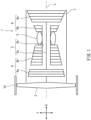
- FIG. 1 is a sectional view of the turbo fan engine 1 according to the embodiment which is viewed from the radial direction.
- the turbo fan engine 1 is, for example, a gas turbine engine used in an aircraft. The use of the gas turbine is not limited to the aircraft.
- the turbo fan engine 1 includes the rotating shaft 2, a fan 3, a compressor 4, a combustor 5, a turbine 6, a casing 7, and a fan case assembly 10.
- the rotating shaft 2 extends in a front-rear direction of the turbo fan engine 1.
- the fan 3 is connected to a front portion of the rotating shaft 2 and rotates together with the rotating shaft 2.
- the compressor 4, the combustor 5, and the turbine 6 are lined up along the rotating shaft 2 in this order from a front side to a rear side.
- the casing 7 accommodates the rotating shaft 2, the compressor 4, the combustor 5, and the turbine 6.
- the casing 7 and the fan case assembly 10 are tubular objects each including an axis that coincides with the rotation axis L of the rotating shaft
- the turbo fan engine 1 is, for example, a two-shaft gas turbine engine, but may be a three-shaft gas turbine engine or the like.
- the compressor 4 includes a low pressure compressor 4a and a high pressure compressor 4b located behind the low pressure compressor 4a.
- the turbine 6 includes a high pressure turbine 6b and a low pressure turbine 6a located behind the high pressure turbine 6b.
- the rotating shaft 2 includes a low pressure shaft 2a and a high pressure shaft 2b.
- the low pressure shaft 2a couples the low pressure compressor 4a to the low pressure turbine 6a, and the high pressure shaft 2b couples the high pressure compressor 4b to the high pressure turbine 6b.
- the high pressure shaft 2b is a tubular shaft including a hollow space therein.
- the low pressure shaft 2a is in the hollow space of the high pressure shaft 2b.
- the low pressure turbine 6a is coupled through the low pressure shaft 2a to the fan 3 located in front of the compressor 4.
- the fan 3 is covered with the tubular fan case assembly 10 from an outside in the radial direction Y
- the fan case assembly 10 is a tubular object including an axis that coincides with the rotation axis L.
- a cylindrical bypass passage is located between the casing 7 and the fan case assembly 10. Air sucked by the fan 3 flows through the bypass passage and is ejected rearward to generate propulsive force.
- the fan case assembly 10 is covered with an outer cover (not shown) from the outside in the radial direction Y
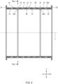
- FIG. 2 is a sectional view of the fan case assembly 10 of FIG. 1 which is viewed from the radial direction.
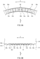
- FIG. 3 is a front view of the fan case assembly 10 of FIG. 2 which is viewed from the axial direction X.
- the fan case assembly 10 includes a fan case 11, a panel set 12, radial elastic bodies 13, a first axial elastic body 14, and a second axial elastic body 15.
- the fan case 11 has a tubular shape including the rotation axis L as a center axis.
- the fan case 11 surrounds the fan 3 from the outside in the radial direction Y Specifically, the fan case 11 includes a fan case main body 20, a front closing plate 21, and a rear closing plate 22.
- the fan case main body 20 has a tubular shape.
- Each of the front closing plate 21 and the rear closing plate 22 is an annular plate having a center located on the rotation axis L.
- the shapes of the front closing plate 21 and the rear closing plate 22 are not especially limited as long as the front closing plate 21 and the rear closing plate 22 can be fixed to the fan case main body 20.
- the front closing plate 21 is detachably fixed to a front end of the fan case main body 20 with a fastener.
- the rear closing plate 22 is detachably fixed to a rear end of the fan case main body 20 with a fastener.
- the front closing plate 21 and the rear closing plate 22 project inward in the radial direction Y beyond an inner peripheral surface 20a of the fan case main body 20.
- One of the front closing plate 21 and the rear closing plate 22 may be fixed to the fan case main body 20 in a non-detachable manner.
- the panel set 12 has a tubular shape that covers the inner peripheral surface 20a of the fan case main body 20.
- the panel set 12 includes panels lined up from the front side to the rear side in the axial direction X.
- the panel set 12 includes a fan track liner panel 30, a first sound absorbing panel 31, and a second sound absorbing panel 32.
- the fan track liner panel 30 is opposed to the fan 3 (see FIG. 1 ) from the outside in the radial direction Y
- the first sound absorbing panel 31 is located at one side (front side) of the fan track liner panel 30 in the axial direction X.
- the second sound absorbing panel 32 is located at the other side (rear side) of the fan track liner panel 30 in the axial direction X.
- the fan case 11 and the panel set 12 are made of different materials.
- a linear expansion coefficient of the fan case 11 and a linear expansion coefficient of the panel set 12 are different from each other.
- the linear expansion coefficient of the fan case 11 is smaller than the linear expansion coefficient of the panel set 12.
- the fan case 11 may be made of fiber-reinforced resin, metal, or the like
- the panel set 12 may be made of metal, resin, fiber-reinforced resin, or the like.
- the fiber-reinforced resin FRP including carbon fiber and epoxy resin is suitable, but another type of FRP may be used.
- As the metal aluminum is suitably used, but another type of metal may be used.
- the fan case 11 and the panel set 12 may be made of the same material.
- the linear expansion coefficient of the fan case 11 and the linear expansion coefficient of the panel set 12 may be equal to each other.
- the fan case 11 (fan case main body 20) and the panel set 12 are located with a radial gap Gr therebetween.
- the radial gap Gr is a space (air layer) between an inner peripheral surface of the fan case 11 and an outer peripheral surface of the panel set 12.
- the fan track liner panel 30 and the first sound absorbing panel 31 are located with a first axial gap Ga1 therebetween.
- the fan track liner panel 30 and the second sound absorbing panel 32 are located with a second axial gap Ga2 therebetween.
- the first axial gap Ga1 and the second axial gap Ga2 are spaces (air layers).
- Each of the fan track liner panel 30, the first sound absorbing panel 31, and the second sound absorbing panel 32 is, for example, a single object having a tubular shape.
- each of the fan track liner panel 30, the first sound absorbing panel 31, and the second sound absorbing panel 32 may be an object including parts that form a tubular shape (for example, an object including a pair of semi-tubular bodies that are engaged with each other to form a tubular shape) or may have a pseudo tubular shape including a C-shaped section.
- each of the panels 30 to 32 may have a substantially tubular shape as a whole.
- An inner peripheral surface of the fan track liner panel 30 is made of a material that is lower in wear resistance than a material of an inner peripheral surface of the first sound absorbing panel 31 and a material of an inner peripheral surface of the second sound absorbing panel 32. To be specific, when the fan 3 contacts the inner peripheral surface of the fan track liner panel 30, the fan track liner panel 30 is worn away, and therefore, the fan 3 is protected.
- Each of the inner peripheral surface of the first sound absorbing panel 31 and the inner peripheral surface of the second sound absorbing panel 32 includes sound absorbing holes.
- Each of the first sound absorbing panel 31 and the second sound absorbing panel 32 includes therein resonance chambers that communicate with the respective sound absorbing holes.
- each of the fan track liner panel 30, the first sound absorbing panel 31, and the second sound absorbing panel 32 may have such a structure that a honeycomb panel is sandwiched between an outer plate and an inner plate from both sides in the radial direction Y
- the inner panel of the fan track liner panel 30 is made of a material that is lower in wear resistance than a material of the inner panel of the first sound absorbing panel 31 and a material of the inner panel of the second sound absorbing panel 32.
- Each of the inner panel of the first sound absorbing panel 31 and the inner panel of the second sound absorbing panel 32 includes the sound absorbing holes.
- the fan case 11 may be made of, for example, fiber-reinforced resin.
- the sound absorbing panels 31 and 32 may be made of, for example, aluminum.
- the honeycomb panel of the fan track liner panel 30 may be made of, for example, meta-aramid fibers including gaps filled with epoxy. This material composition is merely one example, and the present embodiment is not limited to this.
- the radial elastic bodies 13 are located in the radial gap Gr.
- the radial elastic bodies 13 are located between the fan case 11 and the panel set 12.
- the radial elastic bodies 13 are compressed in the radial direction Y by the fan case 11 and the panel set 12.
- the radial elastic bodies 13 are elastically deformable in the radial direction Y
- the radial elastic bodies 13 may be, for example, springs or may be members made of an elastic material, such as rubber.
- the radial elastic bodies 13 are located on the outer peripheral surface of the panel set 12 at regular intervals in the circumferential direction Z.
- the radial elastic bodies 13 may be located on the outer peripheral surface of the panel set 12 at arbitrary intervals in the circumferential direction Z.
- the first axial elastic body 14 is located in the first axial gap Ga1.
- the first axial elastic body 14 is located between the fan track liner panel 30 and the first sound absorbing panel 31.
- the first axial elastic body 14 is compressed in the axial direction X by the fan track liner panel 30 and the first sound absorbing panel 31.
- the second axial elastic body 15 is located in the second axial gap Ga2.
- the second axial elastic body 15 is located between the fan track liner panel 30 and the second sound absorbing panel 32.
- the second axial elastic body 15 is compressed in the axial direction X by the fan track liner panel 30 and the second sound absorbing panel 32.
- the first axial elastic body 14 and the second axial elastic body 15 are elastically deformable in the axial direction X.
- the first axial elastic body 14 and the second axial elastic body 15 may be, for example, springs or may be members made of an elastic material, such as rubber.
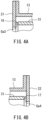
- an axial elastic body 16 may be located in an axial gap Ga3 between the front closing plate 21 and the first sound absorbing panel 31.
- an axial elastic body 17 may be located in an axial gap Ga4 between the rear closing plate 22 and the second sound absorbing panel 32.
- the axial elastic body may be located in a compressed state between at least two adjacent elements selected from the front closing plate 21, the first sound absorbing panel 31, the fan track liner panel 30, the second sound absorbing panel 32, and the rear closing plate 22.
- FIG. 5 is an enlarged view showing the radial elastic body 13 of FIG. 2 and its vicinity.
- the same radial elastic bodies 13 can be used as the radial elastic bodies 13 attached to the first sound absorbing panel 31, the radial elastic bodies 13 attached to the fan track liner panel 30, and the radial elastic bodies 13 attached to the second sound absorbing panel 32. Therefore, in FIG. 5 , the radial elastic body 13 attached to the first sound absorbing panel 31 will be especially described.
- the radial elastic bodies 13 may be different in material, shape, and the like from each other.
- the radial elastic body 13 includes an attaching portion 13a and an elastic portion 13b that is continuous with the attaching portion 13a in the axial direction X.
- the attaching portion 13a is fastened to the first sound absorbing panel 31 with a fastener B1 in an attachment hole 31b of the first sound absorbing panel 31.
- the elastic portion 13b is elastically deformable in the radial direction Y A projecting amount of the elastic portion 13b projecting outward in the radial direction Y from the first sound absorbing panel 31 is larger than that of the fastener B1.
- the attaching portion 13a may be fixed to the first sound absorbing panel 31 with another type of means, such as an adhesive.
- the radial elastic body 13 may be attached to the fan case main body 20 instead of being attached to the first sound absorbing panel 31.
- the radial elastic body 13 is, for example, a plate spring extending in the axial direction X.
- the attaching portion 13a has a shape (for example, a circular-arc shape) corresponding to an outer peripheral surface 31a of the first sound absorbing panel 31.
- the elastic portion 13b includes at least one portion that projects outward in the radial direction Y
- the elastic portion 13b includes one portion that projects in an arch shape.
- One end portion which is opposite to the attaching portion 13a out of both end portions of the radial elastic body 13 in the axial direction X is an end portion 13c that is not fixed. The end portion 13c may be fixed to the first sound absorbing panel 31.
- the elastic portion 13b has a tapered shape that tapers toward the fan case main body 20 of the fan case 11.
- the elastic portion 13b includes a slope surface 13ba that is continuous with the attaching portion 13a.
- the slope surface 13ba is an inclined surface that gradually approaches the outer peripheral surface 31a of the first sound absorbing panel 31 as it approaches the attaching portion 13a.
- the outer peripheral surface 31a of the first sound absorbing panel 31 includes a stopper 31c that is located away from the end portion 13c of the radial elastic body 13 by an arbitrary distance.
- the stopper 31c projects outward in the radial direction Y from the outer peripheral surface 31a of the first sound absorbing panel 31.
- the elastic portion 13b of the radial elastic body 13 is pressed inward in the radial direction Y by the fan case main body 20, and therefore, the first sound absorbing panel 31 is elastically supported by the radial elastic body 13 in the radial direction Y relative to the fan case main body 20.
- the first sound absorbing panel 31 can approach or separate from the fan case main body 20 in the radial direction Y while being supported by the fan case main body 20.
- FIG. 6A is an enlarged view showing the first axial elastic body 14 and its vicinity in a sectional view taken along line VIa-VIa of FIG. 2 .
- FIG. 6B is a diagram showing the first axial elastic body 14 of FIG. 6A and its vicinity which are viewed from the radial direction.
- the first axial elastic body 14 and the second axial elastic body 15 are the same as each other. Therefore, in FIGS. 6A and 6B , the first axial elastic body 14 will be especially described.
- the axial elastic bodies 14 and 15 may be different in material, shape, and the like from each other.
- the first axial elastic body 14 includes an attaching portion 14a and a pair of elastic portions 14b that are continuous with the attaching portion 14a in the circumferential direction Z.
- the attaching portion 14a is fastened to the fan track liner panel 30 with fasteners B2 in attachment holes 30b located on an end surface 30a of the fan track liner panel 30 which faces in the axial direction X.
- the elastic portions 14b are elastically deformable in the axial direction X.
- a projecting amount of the elastic portion 14b projecting in the axial direction X from the end surface 30a of the fan track liner panel 30 is larger than that of the fastener B2.
- the attaching portion 14a may be fixed to the fan track liner panel 30 with another type of means, such as an adhesive.
- the first axial elastic body 14 may be attached to the first sound absorbing panel 31 instead of being attached to the fan track liner panel 30.
- the first axial elastic body 14 is, for example, a plate spring extending in the circumferential direction Z.
- the attaching portion 14a has a shape (for example, a flat plate shape) extending along the end surface 30a of the fan track liner panel 30.
- the elastic portions 14b When viewed from the radial direction Y, the elastic portions 14b includes at least one portion that projects in the axial direction X. In the present embodiment, the elastic portion 14b has a corrugated plate shape. However, the shape of the elastic portion 14b is not limited to this. Both end portions of the first axial elastic body 14 in the circumferential direction Z are end portions 14c that are not fixed.
- the end surface 30a of the fan track liner panel 30 includes stoppers 30c that are opposed to the corresponding end portions 14c of the first axial elastic body 14 in the circumferential direction Z and are located away from the corresponding end portions 14c of the first axial elastic body 14.
- the stoppers 30c project forward in the axial direction X from the end surface 30a of the fan track liner panel 30.
- the elastic portions 14b of the first axial elastic body 14 are pressed in the axial direction X by the first sound absorbing panel 31. Therefore, the fan track liner panel 30 can approach or separate from the first sound absorbing panel 31 in the axial direction X.
- the fan case 11, the fan track liner panel 30, the first sound absorbing panel 31, and the second sound absorbing panel 32 are stably held by the radial elastic bodies 13, the first axial elastic body 14, and the second axial elastic body 15, and the thermal expansion difference and the machining tolerance are absorbed by the elastic deformation of the elastic body between two members. Therefore, problems, such as stress concentration and vibration of the fan case assembly 10, can be prevented from occurring.
- the thermal expansion difference is suitably absorbed.
- the degree of freedom of the selection of materials of the fan case 11 and the panel set 12 can be improved.
- stoppers 30c and 31c that limit the elastic deformation of the elastic bodies 13 to 15 are included, it is possible to prevent a case where the elastic bodies 13 to 15 are excessively and elastically deformed, and therefore, are displaced beyond expectation.
- the panel set 12 can be inserted into the fan case 11 in the axial direction X at the time of the assembling of the fan case assembly 10.
- assembling efficiency can be improved.
- the fan case 11 since the attaching portion 13a of the radial elastic body 13 is attached to the panel set 12 with the fastener B1 in the attachment hole 3 1b of the panel set 12, the fan case 11 does not have to include the attachment hole 31b used to attach the radial elastic body 13. Therefore, the strength of the fan case 11 that is required to have containment performance can be prevented from deteriorating.
- the radial elastic bodies 13, the first axial elastic body 14, and the second axial elastic body 15 can be located at arbitrary positions, the radial elastic bodies 13, the first axial elastic body 14, and the second axial elastic body 15 can flexibly absorb the thermal expansion difference and the machining tolerance among the panels 30 to 32 while stably supporting the fan track liner panel 30, the first sound absorbing panel 31, and the second sound absorbing panel 32.
- FIG. 7 is a sectional view showing a modified example of a peripheral structure of the axial elastic body 14 of FIG. 2 .
- two members for example, a fan track liner panel 130 and a first sound absorbing panel 131 sandwiching the first axial elastic body 14 in the axial direction X include a positioning structure 140 that positions the two members in the radial direction Y
- the positioning structure 140 includes, for example, a circumferential projection 130e that projects in the axial direction X from an inner peripheral edge of an end surface 130a of the fan track liner panel 130.
- the circumferential projection 130e is in contact with an inner peripheral surface of the first sound absorbing panel 131.
- the circumferential projection 130e may project from the first sound absorbing panel 131.
- the fan track liner panel 130 and the first sound absorbing panel 131 can be positioned relative to each other in the radial direction Y Moreover, the circumferential projection 130e can cover the first axial elastic body 14 from an inside in the radial direction Y Since the other components are the same as those in the above embodiment, explanations thereof are omitted.
- FIG. 8 is a diagram showing a radial elastic body 113 of First Modified Example and corresponding to FIG. 5 .
- the radial elastic body 113 of First Modified Example is made of an elastic material (for example, rubber).
- the radial elastic body 113 includes a pair of attaching portions 113a and an elastic portion 113b located between the pair of attaching portions 113a in the axial direction X.
- the attaching portions 113a are fastened to the first sound absorbing panel 31 with the fasteners B1 in the attachment holes 3 1b of the first sound absorbing panel 31.
- the elastic portion 113b includes a portion that projects outward in the radial direction Y A projecting amount of the elastic portion 113b projecting outward in the radial direction Y from the first sound absorbing panel 31 is larger than that of the fastener B1.
- the elastic portion 113b has a tapered shape that tapers toward the fan case main body 20.
- the elastic portion 113b includes a slope surface 113ba that is continuous with the attaching portion 113a.
- the slope surface 113ba is an inclined surface that gradually approaches the outer peripheral surface 31a of the first sound absorbing panel 31 as it approaches the attaching portion 113a.
- both end portions (attaching portions 113a) of the radial elastic body 113 in the axial direction X are fixed to the first sound absorbing panel 31 with the fasteners B1, the radial elastic body 113 is prevented from being worn away by the outer peripheral surface of the first sound absorbing panel 31. Since the other components are the same as those in the above embodiment, explanations thereof are omitted.
- FIG. 9 is a diagram showing Second Modified Example of the radial elastic body 13 and corresponding to FIG. 5 .
- the radial elastic body 13 is attached to the fan case main body 20 instead of being attached to the first sound absorbing panel 31.
- the radial elastic body 13 may be located such that the slope surface 13ba is directed to a side at which the first sound absorbing panel 31 is inserted (i.e., to the front side).
- the attaching portion 13a may be located at the side at which the first sound absorbing panel 31 is inserted, with respect to the elastic portion 13b (i.e., at the front side of the elastic portion 13b). Since the other components are the same as those in the above embodiment, explanations thereof are omitted.
- FIG. 10A is a diagram showing an axial elastic body 114 of First Modified Example and corresponding to FIG. 6A .
- FIG. 10B is a diagram showing the axial elastic body 114 of First Modified Example and corresponding to FIG. 6B .
- the axial elastic body 114 is an annular plate spring.
- the axial elastic body 114 includes: an attaching portion 114a that is part of the annular shape; and an elastic portion 114b that is the rest of the annular shape.
- the attaching portion 114a is fastened to the fan track liner panel 30 with the fastener B2.
- the elastic portion 114b includes an opening 114c that exposes the fastener B2 when viewed from the axial direction X.
- the attaching portion 114a may be fastened to the first sound absorbing panel 31 with the fastener B2.
- the fastener B2 may be covered with the elastic portion 114b.
- the first axial elastic body 114 is pressed by the first sound absorbing panel 31 in the axial direction X with the elastic portion 114b located between the fastener B2 and the first sound absorbing panel 31.
- the elastic portion 114b is pressed by the end surface 31d of the first sound absorbing panel 31 in the axial direction X
- the axial elastic body 114 is elastically deformed such that a contact area of the axial elastic body 114 with respect to the fan track liner panel 30 increases. Therefore, the axial elastic body 114 is prevented from being worn away by the fan track liner panel 30 and the first sound absorbing panel 31. Since the other components are the same as those in the above embodiment, explanations thereof are omitted.
- FIG. 11A is a diagram showing an axial elastic body 214 of Second Modified Example and corresponding to FIG. 6A .
- FIG. 11B is a diagram showing the axial elastic body 214 of Second Modified Example and corresponding to FIG. 6B .
- the axial elastic body 214 is a plate spring that has been subjected to bending.
- the axial elastic body 214 includes an attaching portion 214a and a pair of elastic portions 214b that are continuously located at both sides of the attaching portion 214a in the circumferential direction Z.
- the attaching portion 214a has, for example, a flat plate shape and is fastened to the fan track liner panel 30 with the fastener B2. Moreover, the attaching portion 214a may be fastened to the first sound absorbing panel 31 with the fastener B2. For example, part of each elastic portion 214b may be curved in a C shape or a U shape in a section viewed from the radial direction Y The elastic portions 214b project in the axial direction X beyond the fastener B2. The elastic portions 214b are compressed by the end surface 31d of the first sound absorbing panel 31 in the axial direction X. Since the other components are the same as those in the above embodiment, explanations thereof are omitted.
- FIG. 12A is a diagram showing an axial elastic body 314 of Third Modified Example and corresponding to FIG. 6A .
- FIG. 12B is a diagram showing the axial elastic body 314 of Third Modified Example and corresponding to FIG. 6B .
- the axial elastic body 314 is a plate spring that has been subjected to bending.
- the axial elastic body 314 includes: a pair of attaching portions 314a; a middle elastic portion 314b located between the pair of attaching portions 314a; and side elastic portions 314c located outside the corresponding attaching portions 314a in the circumferential direction Z.
- Each attaching portion 314a has, for example, a flat plate shape and is fastened to the fan track liner panel 30 with the fastener B2. Moreover, the attaching portion 314a may be fastened to the first sound absorbing panel 31 with the fastener B2.
- the middle elastic portion 314b is curved so as to project toward the first sound absorbing panel 31.
- part of each side elastic portion 314c may be curved in a C shape or a U shape in a section viewed from the radial direction Y
- the middle elastic portion 314b and the side elastic portions 314c project in the axial direction X beyond the fasteners B2.
- the middle elastic portion 314b and the side elastic portions 314c are compressed in the axial direction X by the end surface 31d of the first sound absorbing panel 31. Since the other components are the same as those in the above embodiment, explanations thereof are omitted.
- FIG. 13A is a diagram showing an axial elastic body 414 of Fourth Modified Example and corresponding to FIG. 6A .
- FIG. 13B is a diagram showing the axial elastic body 414 of Fourth Modified Example and corresponding to FIG. 6B .
- the axial elastic body 414 is made of an elastic material (for example, rubber).
- the axial elastic body 414 includes an attaching portion 414a and a pair of elastic portions 414b that are continuously located at both sides of the attaching portion 414a in the circumferential direction Z.
- the attaching portion 414a is fastened to the fan track liner panel 30 with the fastener B2.
- the attaching portion 414a may be fastened to the first sound absorbing panel 31 with the fastener B2.
- the elastic portions 414b project in the axial direction X beyond the fastener B2.
- the elastic portions 414b are compressed in the axial direction X by the end surface 31d of the first sound absorbing panel 31. Since the other components are the same as those in the above embodiment, explanations thereof are omitted.
- the present disclosure is not limited to the above embodiment. Modifications, additions, and eliminations may be made with respect to the configuration of the embodiment. For example, some of components or methods in one embodiment may be applied to another embodiment. Some components in an embodiment may be separated and arbitrarily extracted from the other components in the embodiment.
- the radial elastic body 13 or the axial elastic bodies 14 and 15 may be omitted, and the radial gap Gr or the axial gaps Ga1 and Ga2 may be omitted.
- the first axial elastic body 14 or the second axial elastic body 15 may be omitted, and the first axial gap Ga1 or the second axial gap Ga2 may be omitted.
- the axial elastic body may be sandwiched between the front closing plate 21 and the first sound absorbing panel 31 and/or between the rear closing plate 22 and the second sound absorbing panel 32.
Landscapes
- Engineering & Computer Science (AREA)
- Mechanical Engineering (AREA)
- General Engineering & Computer Science (AREA)
- Chemical & Material Sciences (AREA)
- Combustion & Propulsion (AREA)
- Structures Of Non-Positive Displacement Pumps (AREA)
Abstract
Description
- The present disclosure relates to a fan case assembly of a turbo fan engine.
-
PTL 1 discloses a cylindrical fan case assembly surrounding a fan of a turbo fan engine of an aircraft from an outside in a radial direction. The fan case assembly includes: a fan case; a first panel that covers an inner peripheral surface of the fan case and is opposed to the fan; and a second panel that covers the inner peripheral surface of the fan case and is located upstream or downstream of the first panel. Each of the fan case, the first panel, and the second panel is fixed with an adhesive or a bolt. - PTL 1: Published
Japanese Translation of PCT Application No. 2016-513773 - However, when there is a thermal expansion difference or a machining tolerance among the fan case, the first panel, and the second panel, stress concentrates at a coupled portion realized by the adhesive or the bolt. Moreover, when the size of a gap between members increases due to the thermal expansion difference or the machining tolerance among the fan case, the first panel, and the second panel, vibration tends to occur during the operation of the engine.
- A fan case assembly of a turbo fan engine according to one aspect of the present disclosure includes: a tubular fan case surrounding a fan of the turbo fan engine; a tubular panel set covering an inner peripheral surface of the fan case and including panels lined up in an axial direction of the turbo fan engine; and at least one elastic body compressed by two members selected from the fan case and the panels.
- According to the above configuration, the positions of two members selected from the fan case and the panels are stably held by the elastic body, and the thermal expansion difference and the machining tolerance are absorbed by the elastic deformation of the elastic body between the two members. Therefore, stress concentration and vibration of the fan case assembly can be reduced.
- According to one aspect of the present disclosure, stress concentration and vibration of the fan case assembly can be reduced.
-
- FIG. 1 is a sectional view of a turbo fan engine according to an embodiment which is viewed from a radial direction.
- FIG. 2 is a sectional view of a fan case assembly of
FIG. 1 which is viewed from the radial direction. - FIG. 3 is a front view of the fan case assembly of
FIG. 2 which is viewed from an axial direction. - FIGS. 4A and 4B are enlarged sectional views showing a modified example of the fan case assembly of
FIG. 2 . - FIG. 5 is an enlarged view showing a radial elastic body of
FIG. 2 and its vicinity. - FIG. 6A is an enlarged view showing an axial elastic body and its vicinity in a sectional view taken along line VIa-VIa of
FIG. 2 .FIG. 6B is a diagram showing the axial elastic body ofFIG. 6A and its vicinity which are viewed from the radial direction. - FIG. 7 is a sectional view showing a modified example of a peripheral structure of the axial elastic body of
FIG. 2 . - FIG. 8 is a diagram showing First Modified Example of the radial elastic body and corresponding to
FIG. 5 . - FIG. 9 is a diagram showing Second Modified Example of the radial elastic body and corresponding to
FIG. 5 . - FIG. 10A is a diagram showing First Modified Example of the axial elastic body and corresponding to
FIG. 6A .FIG. 10B is a diagram showing First Modified Example of the axial elastic body and corresponding toFIG. 6B . - FIG. 11A is a diagram showing Second Modified Example of the axial elastic body and corresponding to
FIG. 6A .FIG. 11B is a diagram showing Second Modified Example of the axial elastic body and corresponding toFIG. 6B . - FIG. 12A is a diagram showing Third Modified Example of the axial elastic body and corresponding to
FIG. 6A .FIG. 12B is a diagram showing Third Modified Example of the axial elastic body and corresponding toFIG. 6B . - FIG. 13A is a diagram showing Fourth Modified Example of the axial elastic body and corresponding to
FIG. 6A .FIG. 13B is a diagram showing Fourth Modified Example of the axial elastic body and corresponding toFIG. 6B . - Hereinafter, an embodiment will be described with reference to the drawings. In the following description, an axial direction X denotes a direction in which a rotation axis L of a
rotating shaft 2 of aturbo fan engine 1 extends. A radial direction Y denotes a direction orthogonal to the rotation axis X. A circumferential direction Z denotes a direction circumferentially extending around the rotation axis X. Moreover, "front" denotes an upstream side in a direction in which air flows in theturbo fan engine 1, and "rear" denotes a downstream side in the direction in which the air flows in theturbo fan engine 1. -
FIG. 1 is a sectional view of theturbo fan engine 1 according to the embodiment which is viewed from the radial direction. As shown inFIG. 1 , theturbo fan engine 1 is, for example, a gas turbine engine used in an aircraft. The use of the gas turbine is not limited to the aircraft. Theturbo fan engine 1 includes therotating shaft 2, a fan 3, acompressor 4, a combustor 5, aturbine 6, acasing 7, and afan case assembly 10. Therotating shaft 2 extends in a front-rear direction of theturbo fan engine 1. The fan 3 is connected to a front portion of therotating shaft 2 and rotates together with therotating shaft 2. Thecompressor 4, the combustor 5, and theturbine 6 are lined up along therotating shaft 2 in this order from a front side to a rear side. Thecasing 7 accommodates therotating shaft 2, thecompressor 4, the combustor 5, and theturbine 6. Thecasing 7 and thefan case assembly 10 are tubular objects each including an axis that coincides with the rotation axis L of therotating shaft 2. - The
turbo fan engine 1 is, for example, a two-shaft gas turbine engine, but may be a three-shaft gas turbine engine or the like. Thecompressor 4 includes alow pressure compressor 4a and ahigh pressure compressor 4b located behind thelow pressure compressor 4a. Theturbine 6 includes a high pressure turbine 6b and alow pressure turbine 6a located behind the high pressure turbine 6b. Therotating shaft 2 includes alow pressure shaft 2a and ahigh pressure shaft 2b. Thelow pressure shaft 2a couples thelow pressure compressor 4a to thelow pressure turbine 6a, and thehigh pressure shaft 2b couples thehigh pressure compressor 4b to the high pressure turbine 6b. Thehigh pressure shaft 2b is a tubular shaft including a hollow space therein. Thelow pressure shaft 2a is in the hollow space of thehigh pressure shaft 2b. Thelow pressure turbine 6a is coupled through thelow pressure shaft 2a to the fan 3 located in front of thecompressor 4. - The fan 3 is covered with the tubular
fan case assembly 10 from an outside in the radial direction Y Thefan case assembly 10 is a tubular object including an axis that coincides with the rotation axis L. A cylindrical bypass passage is located between thecasing 7 and thefan case assembly 10. Air sucked by the fan 3 flows through the bypass passage and is ejected rearward to generate propulsive force. Thefan case assembly 10 is covered with an outer cover (not shown) from the outside in the radial direction Y -
FIG. 2 is a sectional view of thefan case assembly 10 ofFIG. 1 which is viewed from the radial direction.FIG. 3 is a front view of thefan case assembly 10 ofFIG. 2 which is viewed from the axial direction X. As shown inFIG. 2 , thefan case assembly 10 includes afan case 11, a panel set 12, radialelastic bodies 13, a first axialelastic body 14, and a second axialelastic body 15. Thefan case 11 has a tubular shape including the rotation axis L as a center axis. Thefan case 11 surrounds the fan 3 from the outside in the radial direction Y Specifically, thefan case 11 includes a fan casemain body 20, afront closing plate 21, and arear closing plate 22. - The fan case
main body 20 has a tubular shape. Each of thefront closing plate 21 and therear closing plate 22 is an annular plate having a center located on the rotation axis L. The shapes of thefront closing plate 21 and therear closing plate 22 are not especially limited as long as thefront closing plate 21 and therear closing plate 22 can be fixed to the fan casemain body 20. Thefront closing plate 21 is detachably fixed to a front end of the fan casemain body 20 with a fastener. Therear closing plate 22 is detachably fixed to a rear end of the fan casemain body 20 with a fastener. Thefront closing plate 21 and therear closing plate 22 project inward in the radial direction Y beyond an innerperipheral surface 20a of the fan casemain body 20. One of thefront closing plate 21 and therear closing plate 22 may be fixed to the fan casemain body 20 in a non-detachable manner. - The panel set 12 has a tubular shape that covers the inner
peripheral surface 20a of the fan casemain body 20. The panel set 12 includes panels lined up from the front side to the rear side in the axial direction X. For example, the panel set 12 includes a fantrack liner panel 30, a firstsound absorbing panel 31, and a secondsound absorbing panel 32. The fantrack liner panel 30 is opposed to the fan 3 (seeFIG. 1 ) from the outside in the radial direction Y The firstsound absorbing panel 31 is located at one side (front side) of the fantrack liner panel 30 in the axial direction X. The secondsound absorbing panel 32 is located at the other side (rear side) of the fantrack liner panel 30 in the axial direction X. - The
fan case 11 and the panel set 12 are made of different materials. A linear expansion coefficient of thefan case 11 and a linear expansion coefficient of the panel set 12 are different from each other. For example, the linear expansion coefficient of thefan case 11 is smaller than the linear expansion coefficient of the panel set 12. Specifically, thefan case 11 may be made of fiber-reinforced resin, metal, or the like, and the panel set 12 may be made of metal, resin, fiber-reinforced resin, or the like. As the fiber-reinforced resin, FRP including carbon fiber and epoxy resin is suitable, but another type of FRP may be used. As the metal, aluminum is suitably used, but another type of metal may be used. Thefan case 11 and the panel set 12 may be made of the same material. The linear expansion coefficient of thefan case 11 and the linear expansion coefficient of the panel set 12 may be equal to each other. - The fan case 11 (fan case main body 20) and the panel set 12 are located with a radial gap Gr therebetween. The radial gap Gr is a space (air layer) between an inner peripheral surface of the
fan case 11 and an outer peripheral surface of the panel set 12. - The fan
track liner panel 30 and the firstsound absorbing panel 31 are located with a first axial gap Ga1 therebetween. The fantrack liner panel 30 and the secondsound absorbing panel 32 are located with a second axial gap Ga2 therebetween. The first axial gap Ga1 and the second axial gap Ga2 are spaces (air layers). - Each of the fan
track liner panel 30, the firstsound absorbing panel 31, and the secondsound absorbing panel 32 is, for example, a single object having a tubular shape. However, each of the fantrack liner panel 30, the firstsound absorbing panel 31, and the secondsound absorbing panel 32 may be an object including parts that form a tubular shape (for example, an object including a pair of semi-tubular bodies that are engaged with each other to form a tubular shape) or may have a pseudo tubular shape including a C-shaped section. To be specific, each of thepanels 30 to 32 may have a substantially tubular shape as a whole. - An inner peripheral surface of the fan
track liner panel 30 is made of a material that is lower in wear resistance than a material of an inner peripheral surface of the firstsound absorbing panel 31 and a material of an inner peripheral surface of the secondsound absorbing panel 32. To be specific, when the fan 3 contacts the inner peripheral surface of the fantrack liner panel 30, the fantrack liner panel 30 is worn away, and therefore, the fan 3 is protected. Each of the inner peripheral surface of the firstsound absorbing panel 31 and the inner peripheral surface of the secondsound absorbing panel 32 includes sound absorbing holes. Each of the firstsound absorbing panel 31 and the secondsound absorbing panel 32 includes therein resonance chambers that communicate with the respective sound absorbing holes. - For example, each of the fan
track liner panel 30, the firstsound absorbing panel 31, and the secondsound absorbing panel 32 may have such a structure that a honeycomb panel is sandwiched between an outer plate and an inner plate from both sides in the radial direction Y In this case, for example, the inner panel of the fantrack liner panel 30 is made of a material that is lower in wear resistance than a material of the inner panel of the firstsound absorbing panel 31 and a material of the inner panel of the secondsound absorbing panel 32. Each of the inner panel of the firstsound absorbing panel 31 and the inner panel of the secondsound absorbing panel 32 includes the sound absorbing holes. - The
fan case 11 may be made of, for example, fiber-reinforced resin. Thesound absorbing panels track liner panel 30 may be made of, for example, meta-aramid fibers including gaps filled with epoxy. This material composition is merely one example, and the present embodiment is not limited to this. - The radial
elastic bodies 13 are located in the radial gap Gr. The radialelastic bodies 13 are located between thefan case 11 and the panel set 12. The radialelastic bodies 13 are compressed in the radial direction Y by thefan case 11 and the panel set 12. The radialelastic bodies 13 are elastically deformable in the radial direction Y The radialelastic bodies 13 may be, for example, springs or may be members made of an elastic material, such as rubber. The radialelastic bodies 13 are located on the outer peripheral surface of the panel set 12 at regular intervals in the circumferential direction Z. The radialelastic bodies 13 may be located on the outer peripheral surface of the panel set 12 at arbitrary intervals in the circumferential direction Z. - As shown in
FIG. 2 , the first axialelastic body 14 is located in the first axial gap Ga1. The first axialelastic body 14 is located between the fantrack liner panel 30 and the firstsound absorbing panel 31. The first axialelastic body 14 is compressed in the axial direction X by the fantrack liner panel 30 and the firstsound absorbing panel 31. The second axialelastic body 15 is located in the second axial gap Ga2. The second axialelastic body 15 is located between the fantrack liner panel 30 and the secondsound absorbing panel 32. The second axialelastic body 15 is compressed in the axial direction X by the fantrack liner panel 30 and the secondsound absorbing panel 32. The first axialelastic body 14 and the second axialelastic body 15 are elastically deformable in the axial direction X. The first axialelastic body 14 and the second axialelastic body 15 may be, for example, springs or may be members made of an elastic material, such as rubber. - As shown in
FIG. 4A , an axialelastic body 16 may be located in an axial gap Ga3 between thefront closing plate 21 and the firstsound absorbing panel 31. Moreover, as shown inFIG. 4B , an axialelastic body 17 may be located in an axial gap Ga4 between therear closing plate 22 and the secondsound absorbing panel 32. To be specific, the axial elastic body may be located in a compressed state between at least two adjacent elements selected from thefront closing plate 21, the firstsound absorbing panel 31, the fantrack liner panel 30, the secondsound absorbing panel 32, and therear closing plate 22. -
FIG. 5 is an enlarged view showing the radialelastic body 13 ofFIG. 2 and its vicinity. The same radialelastic bodies 13 can be used as the radialelastic bodies 13 attached to the firstsound absorbing panel 31, the radialelastic bodies 13 attached to the fantrack liner panel 30, and the radialelastic bodies 13 attached to the secondsound absorbing panel 32. Therefore, inFIG. 5 , the radialelastic body 13 attached to the firstsound absorbing panel 31 will be especially described. In consideration of the thermal expansion difference, the machining tolerance, and the like among the firstsound absorbing panel 31, the fantrack liner panel 30, and the secondsound absorbing panel 32, the radialelastic bodies 13 may be different in material, shape, and the like from each other. - As shown in
FIG. 5 , the radialelastic body 13 includes an attachingportion 13a and anelastic portion 13b that is continuous with the attachingportion 13a in the axial direction X. The attachingportion 13a is fastened to the firstsound absorbing panel 31 with a fastener B1 in anattachment hole 31b of the firstsound absorbing panel 31. Theelastic portion 13b is elastically deformable in the radial direction Y A projecting amount of theelastic portion 13b projecting outward in the radial direction Y from the firstsound absorbing panel 31 is larger than that of the fastener B1. The attachingportion 13a may be fixed to the firstsound absorbing panel 31 with another type of means, such as an adhesive. The radialelastic body 13 may be attached to the fan casemain body 20 instead of being attached to the firstsound absorbing panel 31. - The radial
elastic body 13 is, for example, a plate spring extending in the axial direction X. The attachingportion 13a has a shape (for example, a circular-arc shape) corresponding to an outerperipheral surface 31a of the firstsound absorbing panel 31. In an X-Y section (section shown inFIG. 5 ), theelastic portion 13b includes at least one portion that projects outward in the radial direction Y In the present embodiment, theelastic portion 13b includes one portion that projects in an arch shape. However, the shape of theelastic portion 13b is not limited to this. One end portion which is opposite to the attachingportion 13a out of both end portions of the radialelastic body 13 in the axial direction X is anend portion 13c that is not fixed. Theend portion 13c may be fixed to the firstsound absorbing panel 31. - The
elastic portion 13b has a tapered shape that tapers toward the fan casemain body 20 of thefan case 11. Theelastic portion 13b includes a slope surface 13ba that is continuous with the attachingportion 13a. The slope surface 13ba is an inclined surface that gradually approaches the outerperipheral surface 31a of the firstsound absorbing panel 31 as it approaches the attachingportion 13a. - At the time of the assembling of the
fan case assembly 10, when the firstsound absorbing panel 31 is inserted from the front side into the fan casemain body 20 from which thefront closing plate 21 has been detached, the slope surface 13ba is pressed by the fan casemain body 20, and theelastic portion 13b is compressed inward in the radial direction Y At this time, theend portion 13c of the radialelastic body 13 slides on the outerperipheral surface 31a of the firstsound absorbing panel 31 in the axial direction X. - The outer
peripheral surface 31a of the firstsound absorbing panel 31 includes astopper 31c that is located away from theend portion 13c of the radialelastic body 13 by an arbitrary distance. Thestopper 31c projects outward in the radial direction Y from the outerperipheral surface 31a of the firstsound absorbing panel 31. When theelastic portion 13b is pressed by the fan casemain body 20, theend portion 13c slides in the axial direction X so as to approach thestopper 31c, and then, theend portion 13c contacts thestopper 31c. Thus, the sliding of theend portion 13c is restricted. Therefore, the elastic deformation of theelastic portion 13b is limited, and the fan casemain body 20 is prevented from contacting the fastener B1. - The
elastic portion 13b of the radialelastic body 13 is pressed inward in the radial direction Y by the fan casemain body 20, and therefore, the firstsound absorbing panel 31 is elastically supported by the radialelastic body 13 in the radial direction Y relative to the fan casemain body 20. The firstsound absorbing panel 31 can approach or separate from the fan casemain body 20 in the radial direction Y while being supported by the fan casemain body 20. -
FIG. 6A is an enlarged view showing the first axialelastic body 14 and its vicinity in a sectional view taken along line VIa-VIa ofFIG. 2 .FIG. 6B is a diagram showing the first axialelastic body 14 ofFIG. 6A and its vicinity which are viewed from the radial direction. The first axialelastic body 14 and the second axialelastic body 15 are the same as each other. Therefore, inFIGS. 6A and 6B , the first axialelastic body 14 will be especially described. In consideration of the thermal expansion difference, the machining tolerance, and the like among the firstsound absorbing panel 31, the fantrack liner panel 30, and the secondsound absorbing panel 32, the axialelastic bodies - As shown in
FIGS. 6A and 6B , the first axialelastic body 14 includes an attachingportion 14a and a pair ofelastic portions 14b that are continuous with the attachingportion 14a in the circumferential direction Z. The attachingportion 14a is fastened to the fantrack liner panel 30 with fasteners B2 inattachment holes 30b located on anend surface 30a of the fantrack liner panel 30 which faces in the axial direction X. Theelastic portions 14b are elastically deformable in the axial direction X. A projecting amount of theelastic portion 14b projecting in the axial direction X from theend surface 30a of the fantrack liner panel 30 is larger than that of the fastener B2. The attachingportion 14a may be fixed to the fantrack liner panel 30 with another type of means, such as an adhesive. The first axialelastic body 14 may be attached to the firstsound absorbing panel 31 instead of being attached to the fantrack liner panel 30. - The first axial
elastic body 14 is, for example, a plate spring extending in the circumferential direction Z. The attachingportion 14a has a shape (for example, a flat plate shape) extending along theend surface 30a of the fantrack liner panel 30. When viewed from the radial direction Y, theelastic portions 14b includes at least one portion that projects in the axial direction X. In the present embodiment, theelastic portion 14b has a corrugated plate shape. However, the shape of theelastic portion 14b is not limited to this. Both end portions of the first axialelastic body 14 in the circumferential direction Z areend portions 14c that are not fixed. - At the time of the assembling of the
fan case assembly 10, when the firstsound absorbing panel 31 is inserted into the fan casemain body 20 from the front side, anend surface 31d of the firstsound absorbing panel 31 presses theelastic portions 14b of the first axialelastic body 14 in the axial direction X, and theelastic portions 14b are compressed in the axial direction X. At this time, theend portions 14c of the first axialelastic body 14 slide on theend surface 30a of the fantrack liner panel 30 in the circumferential direction Z. - The
end surface 30a of the fantrack liner panel 30 includesstoppers 30c that are opposed to thecorresponding end portions 14c of the first axialelastic body 14 in the circumferential direction Z and are located away from thecorresponding end portions 14c of the first axialelastic body 14. Thestoppers 30c project forward in the axial direction X from theend surface 30a of the fantrack liner panel 30. When theelastic portions 14b are pressed by the firstsound absorbing panel 31, theend portions 14c slide in the circumferential direction Z so as to approach thecorresponding stoppers 30c, and then, theend portions 14c contact thecorresponding stoppers 30c. Thus, the sliding of theend portions 14c is restricted. Therefore, the elastic deformation of theelastic portions 14b is limited, and the firstsound absorbing panel 31 is prevented from contacting the fasteners B2. - The
elastic portions 14b of the first axialelastic body 14 are pressed in the axial direction X by the firstsound absorbing panel 31. Therefore, the fantrack liner panel 30 can approach or separate from the firstsound absorbing panel 31 in the axial direction X. - According to the above-described configuration, the
fan case 11, the fantrack liner panel 30, the firstsound absorbing panel 31, and the secondsound absorbing panel 32 are stably held by the radialelastic bodies 13, the first axialelastic body 14, and the second axialelastic body 15, and the thermal expansion difference and the machining tolerance are absorbed by the elastic deformation of the elastic body between two members. Therefore, problems, such as stress concentration and vibration of thefan case assembly 10, can be prevented from occurring. - Especially, when the linear expansion coefficient of the
fan case 11 and the linear expansion coefficient of the panel set 12 are different from each other, the thermal expansion difference is suitably absorbed. Moreover, the degree of freedom of the selection of materials of thefan case 11 and the panel set 12 can be improved. - Moreover, since the
stoppers elastic bodies 13 to 15 are included, it is possible to prevent a case where theelastic bodies 13 to 15 are excessively and elastically deformed, and therefore, are displaced beyond expectation. - Moreover, since the
elastic portion 13b of the radialelastic body 13 has the tapered shape that tapers in the radial direction Y, the panel set 12 can be inserted into thefan case 11 in the axial direction X at the time of the assembling of thefan case assembly 10. Thus, assembling efficiency can be improved. - Moreover, since the attaching
portion 13a of the radialelastic body 13 is attached to the panel set 12 with the fastener B1 in the attachment hole 3 1b of the panel set 12, thefan case 11 does not have to include theattachment hole 31b used to attach the radialelastic body 13. Therefore, the strength of thefan case 11 that is required to have containment performance can be prevented from deteriorating. - Moreover, since the radial
elastic bodies 13, the first axialelastic body 14, and the second axialelastic body 15 can be located at arbitrary positions, the radialelastic bodies 13, the first axialelastic body 14, and the second axialelastic body 15 can flexibly absorb the thermal expansion difference and the machining tolerance among thepanels 30 to 32 while stably supporting the fantrack liner panel 30, the firstsound absorbing panel 31, and the secondsound absorbing panel 32. -
FIG. 7 is a sectional view showing a modified example of a peripheral structure of the axialelastic body 14 ofFIG. 2 . As shown inFIG. 7 , in the present modified example, two members (for example, a fantrack liner panel 130 and a first sound absorbing panel 131) sandwiching the first axialelastic body 14 in the axial direction X include apositioning structure 140 that positions the two members in the radial direction Y - The
positioning structure 140 includes, for example, acircumferential projection 130e that projects in the axial direction X from an inner peripheral edge of anend surface 130a of the fantrack liner panel 130. Thecircumferential projection 130e is in contact with an inner peripheral surface of the firstsound absorbing panel 131. Thecircumferential projection 130e may project from the firstsound absorbing panel 131. - Therefore, the fan
track liner panel 130 and the firstsound absorbing panel 131 can be positioned relative to each other in the radial direction Y Moreover, thecircumferential projection 130e can cover the first axialelastic body 14 from an inside in the radial direction Y Since the other components are the same as those in the above embodiment, explanations thereof are omitted. -
FIG. 8 is a diagram showing a radialelastic body 113 of First Modified Example and corresponding toFIG. 5 . As shown inFIG. 8 , the radialelastic body 113 of First Modified Example is made of an elastic material (for example, rubber). The radialelastic body 113 includes a pair of attachingportions 113a and anelastic portion 113b located between the pair of attachingportions 113a in the axial direction X. The attachingportions 113a are fastened to the firstsound absorbing panel 31 with the fasteners B1 in the attachment holes 3 1b of the firstsound absorbing panel 31. In the X-Y section, theelastic portion 113b includes a portion that projects outward in the radial direction Y A projecting amount of theelastic portion 113b projecting outward in the radial direction Y from the firstsound absorbing panel 31 is larger than that of the fastener B1. - The
elastic portion 113b has a tapered shape that tapers toward the fan casemain body 20. Theelastic portion 113b includes a slope surface 113ba that is continuous with the attachingportion 113a. The slope surface 113ba is an inclined surface that gradually approaches the outerperipheral surface 31a of the firstsound absorbing panel 31 as it approaches the attachingportion 113a. - At the time of the assembling, when the first
sound absorbing panel 31 is inserted from the front side into the fan casemain body 20 from which thefront closing plate 21 has been detached, the slope surface 113ba is pressed by the fan casemain body 20, and theelastic portion 113b is compressed inward in the radial direction Y Finally, a surface of theelastic portion 113b which is located at an outside in the radial direction Y is compressed inward in the radial direction Y by the inner peripheral surface of the fan casemain body 20. Since both end portions (attachingportions 113a) of the radialelastic body 113 in the axial direction X are fixed to the firstsound absorbing panel 31 with the fasteners B1, the radialelastic body 113 is prevented from being worn away by the outer peripheral surface of the firstsound absorbing panel 31. Since the other components are the same as those in the above embodiment, explanations thereof are omitted. -
FIG. 9 is a diagram showing Second Modified Example of the radialelastic body 13 and corresponding toFIG. 5 . As shown inFIG. 9 , in Second Modified Example, the radialelastic body 13 is attached to the fan casemain body 20 instead of being attached to the firstsound absorbing panel 31. In this case, the radialelastic body 13 may be located such that the slope surface 13ba is directed to a side at which the firstsound absorbing panel 31 is inserted (i.e., to the front side). The attachingportion 13a may be located at the side at which the firstsound absorbing panel 31 is inserted, with respect to theelastic portion 13b (i.e., at the front side of theelastic portion 13b). Since the other components are the same as those in the above embodiment, explanations thereof are omitted. -
FIG. 10A is a diagram showing an axialelastic body 114 of First Modified Example and corresponding toFIG. 6A .FIG. 10B is a diagram showing the axialelastic body 114 of First Modified Example and corresponding toFIG. 6B . As shown inFIGS. 10A and 10B , the axialelastic body 114 is an annular plate spring. The axialelastic body 114 includes: an attachingportion 114a that is part of the annular shape; and anelastic portion 114b that is the rest of the annular shape. The attachingportion 114a is fastened to the fantrack liner panel 30 with the fastener B2. Theelastic portion 114b includes anopening 114c that exposes the fastener B2 when viewed from the axial direction X. The attachingportion 114a may be fastened to the firstsound absorbing panel 31 with the fastener B2. The fastener B2 may be covered with theelastic portion 114b. - The first axial
elastic body 114 is pressed by the firstsound absorbing panel 31 in the axial direction X with theelastic portion 114b located between the fastener B2 and the firstsound absorbing panel 31. When theelastic portion 114b is pressed by theend surface 31d of the firstsound absorbing panel 31 in the axial direction X, the axialelastic body 114 is elastically deformed such that a contact area of the axialelastic body 114 with respect to the fantrack liner panel 30 increases. Therefore, the axialelastic body 114 is prevented from being worn away by the fantrack liner panel 30 and the firstsound absorbing panel 31. Since the other components are the same as those in the above embodiment, explanations thereof are omitted. -
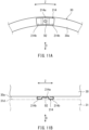
FIG. 11A is a diagram showing an axialelastic body 214 of Second Modified Example and corresponding toFIG. 6A .FIG. 11B is a diagram showing the axialelastic body 214 of Second Modified Example and corresponding toFIG. 6B . As shown inFIGS. 11A and 11B , the axialelastic body 214 is a plate spring that has been subjected to bending. The axialelastic body 214 includes an attachingportion 214a and a pair ofelastic portions 214b that are continuously located at both sides of the attachingportion 214a in the circumferential direction Z. - The attaching
portion 214a has, for example, a flat plate shape and is fastened to the fantrack liner panel 30 with the fastener B2. Moreover, the attachingportion 214a may be fastened to the firstsound absorbing panel 31 with the fastener B2. For example, part of eachelastic portion 214b may be curved in a C shape or a U shape in a section viewed from the radial direction Y Theelastic portions 214b project in the axial direction X beyond the fastener B2. Theelastic portions 214b are compressed by theend surface 31d of the firstsound absorbing panel 31 in the axial direction X. Since the other components are the same as those in the above embodiment, explanations thereof are omitted. -
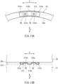
FIG. 12A is a diagram showing an axialelastic body 314 of Third Modified Example and corresponding toFIG. 6A .FIG. 12B is a diagram showing the axialelastic body 314 of Third Modified Example and corresponding toFIG. 6B . As shown inFIGS. 12A and 12B , the axialelastic body 314 is a plate spring that has been subjected to bending. The axialelastic body 314 includes: a pair of attachingportions 314a; a middleelastic portion 314b located between the pair of attachingportions 314a; and sideelastic portions 314c located outside the corresponding attachingportions 314a in the circumferential direction Z. - Each attaching
portion 314a has, for example, a flat plate shape and is fastened to the fantrack liner panel 30 with the fastener B2. Moreover, the attachingportion 314a may be fastened to the firstsound absorbing panel 31 with the fastener B2. The middleelastic portion 314b is curved so as to project toward the firstsound absorbing panel 31. For example, part of each sideelastic portion 314c may be curved in a C shape or a U shape in a section viewed from the radial direction Y The middleelastic portion 314b and the sideelastic portions 314c project in the axial direction X beyond the fasteners B2. The middleelastic portion 314b and the sideelastic portions 314c are compressed in the axial direction X by theend surface 31d of the firstsound absorbing panel 31. Since the other components are the same as those in the above embodiment, explanations thereof are omitted. -
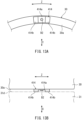
FIG. 13A is a diagram showing an axialelastic body 414 of Fourth Modified Example and corresponding toFIG. 6A .FIG. 13B is a diagram showing the axialelastic body 414 of Fourth Modified Example and corresponding toFIG. 6B . As shown inFIGS. 13A and 13B , the axialelastic body 414 is made of an elastic material (for example, rubber). The axialelastic body 414 includes an attachingportion 414a and a pair ofelastic portions 414b that are continuously located at both sides of the attachingportion 414a in the circumferential direction Z. The attachingportion 414a is fastened to the fantrack liner panel 30 with the fastener B2. Moreover, the attachingportion 414a may be fastened to the firstsound absorbing panel 31 with the fastener B2. Theelastic portions 414b project in the axial direction X beyond the fastener B2. Theelastic portions 414b are compressed in the axial direction X by theend surface 31d of the firstsound absorbing panel 31. Since the other components are the same as those in the above embodiment, explanations thereof are omitted. - The present disclosure is not limited to the above embodiment. Modifications, additions, and eliminations may be made with respect to the configuration of the embodiment. For example, some of components or methods in one embodiment may be applied to another embodiment. Some components in an embodiment may be separated and arbitrarily extracted from the other components in the embodiment. The radial
elastic body 13 or the axialelastic bodies elastic body 14 or the second axialelastic body 15 may be omitted, and the first axial gap Ga1 or the second axial gap Ga2 may be omitted. The axial elastic body may be sandwiched between thefront closing plate 21 and the firstsound absorbing panel 31 and/or between therear closing plate 22 and the secondsound absorbing panel 32. -
- 1 turbo fan engine
- 3 fan
- 10 fan case assembly
- 11 fan case
- 12 panel set
- 13, 113 radial elastic body
- 13a, 113a attaching portion
- 13b, 113b elastic portion
- 14, 114, 214, 314, 414 first axial elastic body
- 14a, 114a, 214a, 314a, 414a attaching portion
- 14b, 114b, 214b, 314b, 314c, 414b elastic portion
- 15 second axial elastic body
- 20 fan case main body
- 21 front closing plate
- 22 rear closing plate
- 30, 130 fan track liner panel
- 30c stopper
- 31, 131 first sound absorbing panel
- 31c stopper
- 32 second sound absorbing panel
- Gr radial gap
- Ga1 first axial gap
- Ga2 second axial gap
- B1, B2 fastener
- L rotation axis
- X axial direction
- Y radial direction
- Z circumferential direction
Claims (10)
- A fan case assembly of a turbo fan engine, the fan case assembly comprising:a tubular fan case surrounding a fan of the turbo fan engine from an outside in a radial direction;a tubular panel set covering an inner peripheral surface of the fan case and including panels lined up in an axial direction of the turbo fan engine; andat least one elastic body compressed by two members selected from the fan case and the panels.
- The fan case assembly according to claim 1, wherein linear expansion coefficients of the two members are different from each other.
- The fan case assembly according to claim 1 or 2, wherein one of the two members includes a stopper that limits elastic deformation of the elastic body.
- The fan case assembly according to any one of claims 1 to 3, wherein the at least one elastic body includes a radial elastic body compressed by the fan case and the panel set in the radial direction.
- The fan case assembly according to claim 4, wherein:the radial elastic body includesan attaching portion attached to one of the panel set and the fan case andan elastic portion compressed by the other of the panel set and the fan case in the radial direction; andthe elastic portion has a tapered shape.
- The fan case assembly according to claim 5, wherein:the panel set includes an attachment hole; andthe attaching portion of the radial elastic body is attached to the panel set with a fastener in the attachment hole of the panel set.
- The fan case assembly according to any one of claims 1 to 6, wherein the at least one elastic body includes at least one axial elastic body compressed by the panels in the axial direction.
- The fan case assembly according to claim 7, wherein:the panels includea first sound absorbing panel,a second sound absorbing panel, anda fan track liner panel located between the first sound absorbing panel and the second sound absorbing panel in the axial direction and opposed to the fan in the radial direction; andthe at least one axial elastic body includesa first axial elastic body compressed by the fan track liner panel and the first sound absorbing panel in the axial direction anda second axial elastic body compressed by the fan track liner panel and the second sound absorbing panel in the axial direction.
- The fan case assembly according to any one of claims 1 to 6, wherein:the fan case includesa fan case main body located outside the panel set in the radial direction anda front closing plate and a rear closing plate which are respectively located at a front end and rear end of the panel set in the axial direction and are fixed to the fan case main body; andthe at least one elastic body includes at least one axial elastic body compressed in the axial direction by two adjacent elements selected from the front closing plate, the panels, and the rear closing plate.
- The fan case assembly according to claim 9, wherein:the panels includea first panel opposed to the front closing plate in the axial direction anda second panel opposed to the rear closing plate in the axial direction; andthe at least one axial elastic body includes an axial elastic body compressed in the axial direction by the front closing plate and the first panel or compressed in the axial direction by the rear closing plate and the second panel.
Applications Claiming Priority (1)
| Application Number | Priority Date | Filing Date | Title |
|---|---|---|---|
| PCT/JP2021/014003 WO2022208801A1 (en) | 2021-03-31 | 2021-03-31 | Fan case assembly for turbofan engine |
Publications (2)
| Publication Number | Publication Date |
|---|---|
| EP4317662A1 true EP4317662A1 (en) | 2024-02-07 |
| EP4317662A4 EP4317662A4 (en) | 2025-01-29 |
Family
ID=83458244
Family Applications (1)
| Application Number | Title | Priority Date | Filing Date |
|---|---|---|---|
| EP21934966.9A Pending EP4317662A4 (en) | 2021-03-31 | 2021-03-31 | FAN HOUSING ASSEMBLY FOR A TURBOFAN ENGINE |
Country Status (4)
| Country | Link |
|---|---|
| US (1) | US12560131B2 (en) |
| EP (1) | EP4317662A4 (en) |
| JP (1) | JP7445822B2 (en) |
| WO (1) | WO2022208801A1 (en) |
Family Cites Families (25)
| Publication number | Priority date | Publication date | Assignee | Title |
|---|---|---|---|---|
| US3507355A (en) * | 1969-05-22 | 1970-04-21 | Rohr Corp | Multi-layer face material for sound absorptive duct lining material |
| US4149824A (en) * | 1976-12-23 | 1979-04-17 | General Electric Company | Blade containment device |
| GB9223593D0 (en) * | 1992-11-11 | 1992-12-23 | Rolls Royce Plc | Gas turbine engine fan blade assembly |
| US5267828A (en) * | 1992-11-13 | 1993-12-07 | General Electric Company | Removable fan shroud panel |
| JPH09195799A (en) * | 1996-01-17 | 1997-07-29 | Mitsubishi Heavy Ind Ltd | Combustor spring seal device |
| GB0308147D0 (en) * | 2003-04-09 | 2003-05-14 | Rolls Royce Plc | A seal |
| GB2407344B (en) * | 2003-10-22 | 2006-02-22 | Rolls Royce Plc | A liner for a gas turbine engine casing |
| GB0326544D0 (en) * | 2003-11-14 | 2003-12-17 | Rolls Royce Plc | Variable stator vane arrangement for a compressor |
| GB0505246D0 (en) * | 2005-03-15 | 2005-04-20 | Rolls Royce Plc | Engine noise |
| GB0916823D0 (en) * | 2009-09-25 | 2009-11-04 | Rolls Royce Plc | Containment casing for an aero engine |
| GB201103682D0 (en) * | 2011-03-04 | 2011-04-20 | Rolls Royce Plc | A turbomachine casing assembly |
| GB201120557D0 (en) | 2011-11-30 | 2012-01-11 | Rolls Royce Plc | A turbomachine casing assembly |
| US9255489B2 (en) * | 2012-02-06 | 2016-02-09 | United Technologies Corporation | Clearance control for gas turbine engine section |
| WO2014137411A1 (en) | 2013-03-04 | 2014-09-12 | Rolls-Royce Corporation | Fan track liner assembly with a spring element |
| FR3003303B1 (en) | 2013-03-15 | 2017-06-30 | Snecma | TURBOMACHINE, SUCH AS A TURBOJET OR AIRCRAFT TURBOPROPULSER |
| EP4019754B1 (en) * | 2013-03-15 | 2026-03-11 | RTX Corporation | Acoustic liner with varied properties |
| JP2015106240A (en) * | 2013-11-29 | 2015-06-08 | 富士フイルム株式会社 | Conductive film and touch panel |
| US9592918B2 (en) * | 2014-06-23 | 2017-03-14 | Rohr, Inc. | Acoustic liner |
| GB201416764D0 (en) | 2014-09-23 | 2014-11-05 | Rolls Royce Plc | Gas turbine engine |
| GB201417415D0 (en) | 2014-10-02 | 2014-11-19 | Rolls Royce Plc | Fan track liner assembly |
| US10837368B2 (en) * | 2017-02-24 | 2020-11-17 | Mra Systems, Llc | Acoustic liner and method of forming an acoustic liner |
| US10539156B2 (en) * | 2017-03-07 | 2020-01-21 | United Technologies Corporation | Variable displacement flutter damper for a turbofan engine |
| US10480530B2 (en) * | 2017-08-25 | 2019-11-19 | United Technologies Corporation | Fan Containment case for gas turbine engines |
| FR3095674B1 (en) * | 2019-05-03 | 2021-04-16 | Safran Aircraft Engines | Thrust reverser grille including acoustic treatment |
| FR3097260B1 (en) * | 2019-06-12 | 2021-06-11 | Safran Aircraft Engines | Turbojet fan housing |
-
2021
- 2021-03-31 EP EP21934966.9A patent/EP4317662A4/en active Pending
- 2021-03-31 WO PCT/JP2021/014003 patent/WO2022208801A1/en not_active Ceased
- 2021-03-31 US US18/283,965 patent/US12560131B2/en active Active
- 2021-03-31 JP JP2023510080A patent/JP7445822B2/en active Active
Also Published As
| Publication number | Publication date |
|---|---|
| JP7445822B2 (en) | 2024-03-07 |
| JPWO2022208801A1 (en) | 2022-10-06 |
| US20240167434A1 (en) | 2024-05-23 |
| US12560131B2 (en) | 2026-02-24 |
| EP4317662A4 (en) | 2025-01-29 |
| WO2022208801A1 (en) | 2022-10-06 |
Similar Documents
| Publication | Publication Date | Title |
|---|---|---|
| US10001028B2 (en) | Dual spring bearing support housing | |
| US11536454B2 (en) | Combustor wall assembly for gas turbine engine | |
| EP2841715B1 (en) | Apparatus and method for assembling a damper bearing assembly | |
| US12466570B2 (en) | Aircraft provided with an exhaust duct coupled to a stabilization system | |
| EP3012494B1 (en) | Sliding seal | |
| US10464683B2 (en) | Aircraft engine assembly, comprising flexible force transmitting devices radially arranged between the thrust reversal cowls and the engine | |
| EP3101234B1 (en) | Composite piston ring seal for axially and circumferentially translating ducts | |
| US10578026B2 (en) | Duct blocker seal assembly for a gas turbine engine | |
| JP2018090112A (en) | Seal structure for aircraft, and aircraft | |
| EP1403486B1 (en) | Acoustic-structural LPC splitter | |
| EP4177505B1 (en) | Joint assembly and method of manufacturing thereof | |
| US12560131B2 (en) | Fan case assembly of turbo fan engine | |
| EP4015777B1 (en) | Bypass duct fairing installation of a turbofan gas turbine engine | |
| US12065985B2 (en) | Sealing assembly for a turbine ejection cone | |
| US11118458B2 (en) | Combination for sealing a gap between turbomachine blades and for reducing vibrations of the turbomachine blades | |
| CN104554736A (en) | Gimbal pin for jet propulsion system | |
| CN108431502B (en) | Gas turbine engine | |
| KR102697340B1 (en) | Exhaust duct assembly and aircraft using the exhaust duct assembly | |
| US9074534B2 (en) | Clamshell seal | |
| JP2024025379A (en) | gas turbine assembly | |
| US20190162134A1 (en) | Retention of a nozzle assembly for an engine |
Legal Events
| Date | Code | Title | Description |
|---|---|---|---|
| STAA | Information on the status of an ep patent application or granted ep patent |
Free format text: STATUS: THE INTERNATIONAL PUBLICATION HAS BEEN MADE |
|
| PUAI | Public reference made under article 153(3) epc to a published international application that has entered the european phase |
Free format text: ORIGINAL CODE: 0009012 |
|
| STAA | Information on the status of an ep patent application or granted ep patent |
Free format text: STATUS: REQUEST FOR EXAMINATION WAS MADE |
|
| 17P | Request for examination filed |
Effective date: 20231009 |
|
| AK | Designated contracting states |
Kind code of ref document: A1 Designated state(s): AL AT BE BG CH CY CZ DE DK EE ES FI FR GB GR HR HU IE IS IT LI LT LU LV MC MK MT NL NO PL PT RO RS SE SI SK SM TR |
|
| DAV | Request for validation of the european patent (deleted) | ||
| DAX | Request for extension of the european patent (deleted) | ||
| A4 | Supplementary search report drawn up and despatched |
Effective date: 20250108 |
|
| RIC1 | Information provided on ipc code assigned before grant |
Ipc: F01D 25/28 20060101ALI20241223BHEP Ipc: F01D 25/24 20060101ALI20241223BHEP Ipc: F01D 21/04 20060101ALI20241223BHEP Ipc: F02K 3/06 20060101ALI20241223BHEP Ipc: F02C 7/00 20060101AFI20241223BHEP |